temporal surface tracking using mesh evolution -...
TRANSCRIPT

Temporal Surface Tracking using Mesh Evolution
Kiran Varanasi, Andrei Zaharescu, Edmond Boyer, Radu Horaud
LJK - INRIA Rhone-Alpes, France
Abstract. In this paper, we address the problem of surface tracking in multiplecamera environments and over time sequences. In order to fully track a surfaceundergoing significant deformations, we cast the problem asa mesh evolutionover time. Such an evolution is driven by 3D displacement fields estimated be-tween meshes recovered independently at different time frames. Geometric andphotometric information is used to identify a robust set of matching vertices. Thisprovides a sparse displacement field that is densified over the mesh by Laplaciandiffusion. In contrast to existing approaches that evolve meshes, we do not assumea known model or a fixed topology. The contribution is a novel mesh evolutionbased framework that allows to fully track, over long sequences, an unknown sur-face encountering deformations, including topological changes. Results on verychallenging and publicly available image based 3D mesh sequences demonstratethe ability of our framework to efficiently recover surface motions .
1 Introduction
Tracking the surface of moving objects is of central importance when modeling dy-namic scenes using multiple videos. This key step in the modeling pipeline yieldstemporal correspondences which are necessary when considering motion related ap-plications such as motion capture. Furthermore, it allows recovery of improved andconsistent descriptions of object shapes and appearances.
In this work we address the problem of capturing the evolution of a moving anddeforming surface, in particular moving human bodies, given multiple videos. A largevariety of directions can be followed, depending on thea priori knowledge of the ob-served shape, on the representation chosen for surfaces andon the information takeninto account for deformations.Model-based approachesassume a known model of theobserved surface, which is tracked over time sequences, hence solving for time cor-respondences. This model can be locally rigid, e.g [1,2,3], or deformable, e.g. [4,5].Unfortunately, exact models need to be available, which is seldom the case in generalsituations. In particular, the topology of the surface can evolve over time as shown inFigure1. As a consequence, approaches in this category are restricted to specific sce-narios.
In contrast, non model-based approaches try to find displacement fields between2 different instants in the sequence. In this category,scene flow approachesconsiderdense vector fields with various representations includingvoxels [6,7], implicit rep-resentations [8] or meshes [9]. However, the associated differential methods are lim-ited to small displacements between successive frames. Alternatively,feature-basedapproaches[10,11,12] consider meshes and allow for larger motions by casting the

2 Kiran Varanasi, Andrei Zaharescu, Edmond Boyer, Radu Horaud
(a) (b) (c)
Fig. 1. An example of a surface for which the topology can hardly be known in advance.The belt of the dress forms a new protrusion that appears and disappears (a)-(b). (c)Dense point trajectories computed from (a) to (b)
problem as a labeling between2 meshes using local geometric or photometric informa-tion. This labeling solves for partial correspondences between2 frames only and mightlose efficiency when applied over long sequences, in particular as topological changesoccur. Our objective is different but complementary and targeted at providing full meshevolution over time sequences.
Our approach is grounded on the observation that natural surfaces are usually arbi-trary shaped and difficult to modela priori. In addition, shapes can significantly evolveover a time sequence. For instance, human bodies are usuallycovered by clothes whosetopologies can change. To handle such deformations, we use meshes which are mor-phed from one frame to another. Like feature-based approaches, we use photometriccues provided by images and geometric cues provided by the recovered meshes. How-ever, instead of looking for a dense match between the vertices of the2 meshes, we usea sparse, but robust set of matches and its associated displacement vector field to drivea full consistent mesh evolution, with possible topological changes. This approach pro-vides both a consistent surface evolution over time and dense point trajectories on thesurface.
The framework we propose assumes little about the observed surface, thus relaxingthe constraints for markers, known models or limited deformations and displacements.It allows for the recovery of trajectories of points, as shown in Figure1, on a surface un-dergoing significant deformations including topological changes. Instead of using tra-ditionalEulerian methodse.g. level sets [13], a major innovation is to cast the problemwithin a mesh evolution framework that performs mesh morphing, thereby avoidingEulerian limitations such as complexity and inappropriateness for tracking interfaceproperties, e.g. vector displacements.
The remainder of this paper is organized as follows. Relatedworks are reviewed insection2. The proposed approach is outlined in section3. The recovery of displacementvector fields is described in section4 and5. The mesh deformation is then explained insection6. Experimental results obtained with publicly available sequences are shownin section7, before concluding in section8.
Temporal Surface Tracking using Mesh Evolution 3
2 Related Work
Surfaces observed in multiple views can be fully tracked through a deformable model,which is fitted to image related observations, see for instance [14] for a review on 3Ddeformable models. This operation appears to be difficult, unless a precise model isavailable. This is particularly true with recent works [9,15] that propose to use a laser-scanned model of the surface prior to tracking. Unfortunately, precise models will notbe available in general situation. Moreover the fixed topology assumption significantlylimits the application domain.
An alternative is to directly estimate surface motions between temporal frames anda significant effort has been put in that direction over the past years.Scene flow ap-proachesrecover dense motion fields using derivatives of the image signal [6,7,16]. In[8] this is used within a variational framework to fully track surfaces using level sets. Asnoticed in [12], flow-based approaches are nevertheless limited to small displacements,as a consequence of finite difference approximations of derivatives.
Another class of approaches solve for shape matching. Assume that shape models,e.g. meshes, can be recovered from images independently over time sequences, usingfor instance [17,18,8]. Then temporal correspondences can be obtained through ver-tex mapping between successive meshes. While providing displacement fields betweenframes, temporal correspondences yet only partially solvethe problem of surface track-ing since the transformation that maps a surface onto another remains unknown. Nev-ertheless, this can be seen as a first step towards full surface tracking. The associatedlabeling problem can be solved in various ways. Point based approaches, e.g. [19,20],register sets of points but do not account for shape information, i.e. mesh connectiv-ity. More closely related to our framework, numerous mesh based approaches havebeen proposed. Some solve for correspondences indirectly through embeddings, e.g.[21,22,23], with the price of an often difficult intermediate step. Other approaches by-pass this step and directly seek correspondences between meshes. For instance [10,11]successfully match2 different poses of apropermesh, e.g. a range-scanned model, us-ing geometric features only. However, these approaches do not easily extend to real ob-jects’ surfaces recovered from images since the associatedmeshes can vary drasticallybetween successive frames and furthermore, their topologies can change. In that case,photometric cues are advantageously added to geometric features to make the labelingfeasible as in [12]. While allowing for large motions, labeling approaches seek densecorrespondences, which are difficult to obtain on a regular basis over long sequences.
To the best of our knowledge, no previous work has attempted to perform thefull tracking of an unknown mesh undergoing deformations with possibly topologi-cal changes, using multiple videos. Our method bridges the gap between model-basedand non model-based approaches since we evolve a mesh using temporal correspon-dences. To this purpose, we build on some of the ideas alreadyused in the approachesmentioned above. We combine the interest of both photometric and geometric cues forrobust matching [12] with Laplacian diffusion [9] to get a dense displacement field. Theresulting vector field is used to initialize a consistent mesh evolution between succes-sive frames. To demonstrate the robustness of our scheme, wehave used challengingreal data sets with large motion and topological changes.
4 Kiran Varanasi, Andrei Zaharescu, Edmond Boyer, Radu Horaud
(a)
(e)(d) (f) (g)
(c)(b)
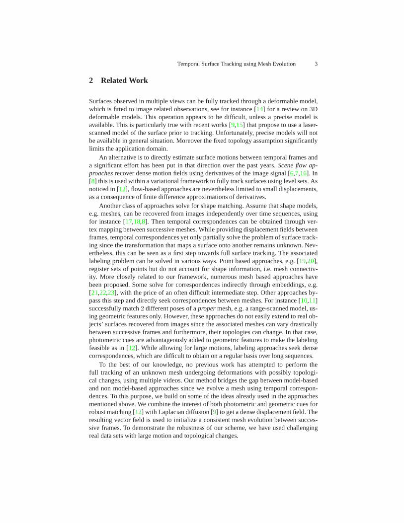
Fig. 2. The different consecutive steps of the proposed framework:(a) original meshesSt andMt+1; (b) features extracted; (c) feature matching; (d) the associated sparse-displacement; (e)-(f) the dense displacement field after Laplacian diffusion; (g) mesh-morphing (observe the topological change that takes place around the right arm of themodel - the right elbow de-attaches from the body, creating agenus change).
3 Approach Outline
We consider multiple camera environments and we assume thatmultiple calibratedvideos of an object with closed surfaces are available. We also assume that 3D meshmodelsMt∈[1..n] of the object at different time instances[1..n] estimated using multi-view 3D modeling approaches, e.g. [17,18,8], are available. These meshesMt∈[1..n]
correspond to discrete values of the time continuous meshSt. In order to recoverSt,the mapping ofSt ontoMt+1 is iteratively estimated using the following3 consecutivesteps, starting withS1 = M1:
1. Sparse match: photometric and geometric cues are used to match a set of pointsbetweenSt andMt+1 (see Figure2-c). Unlike previous approaches, only a sparseset of correspondences is expected.
2. Motion diffusion: the identified correspondences define asparse displacement fieldover St (cf. figure 2-d). This field is propagated over all vertices by Laplaciandiffusion hence preserving local shape details [24] (cf. Figure2-e).
3. Mesh evolution: The dense displacement field is applied tothe vertices ofSt yield-ing a new mesh. The resulting meshSt is then morphed toMt+1 by minimizingthe signed distance toMt+1 (cf. Figure2-fg). Mesh consistency within the opti-mization is enforced using [25]. The final optimized mesh definesSt+1.

Temporal Surface Tracking using Mesh Evolution 5
The Laplacian diffusion allows a partial vertex matching only and yields to a goodestimation of the motion at all vertex locations. Nevertheless, an additional step is re-quired to guarantee that the resulting mesh fits the observationsMt∈[1..n] and also toguaranty its correctness, e.g. manifoldness. This is in contrast with the work [9] whichalso uses Laplacian diffusion to evolve a reference mesh to the observed posture, butwithout refinement and therefore without guaranties. The3 above steps are detailed inthe following sections.
4 Feature Matching
The primary step of our approach is to obtain a set of good feature matches across thetwo frames. In contrast to the labeling approaches mentioned previously, we do notintend here to produce a dense match over mesh vertices, but only a robust selection.To this end, we first detect a set of interest points and provide them with a varietyof distinctive features (photometric and geometric). These sets of feature vectors arethen matched across in an exhaustive manner, to compute a preliminary set of potentialmatches. The error of the matching is defined in terms of difference between the differ-ent feature vectors. We employ a two-step minimization procedure (a coarse step willguide a finer step) in order to avoid local minima. We detail each of these steps in thefollowing subsections.
4.1 Feature Extraction
For each frame, we are provided with a 3D mesh representationSt coupled with a setof imagesIt
i depicting camera views of the object from different angles.
Image Features.We use corners as image features. If silhouettes are available, we usethem to constrain the features (in practice, we erode the silhouettes byα = 3 pixelsto eliminate the features close to the boundary). The feature points are computed asmaxima of the determinant of the image Hessian matrix. We have chosen Speeded-UpRobust Features (SURF) [26] as an image descriptors, because of their robustness inwide-baseline stereo and because of their increased speed of computation due to integralimages. We back-project the detected interest points onto the 3D mesh and assign thecorresponding SURF feature, together with color features,i.e. hue, saturation and value(HSV). The color for the 3-D point is calculated as the mediancolor in the visiblecameras. Figure3-a illustrates the distribution of the feature points over asample 3Dmesh.
Mesh Features.Geodesic distances between mesh points offer crucial information inmatching non rigid shapes. We use a feature called thenormalized geodesic integral[27], which is defined as:
µ(V ) =
∫
P∈S
G(V, P )dS , µn(V ) =µ(V ) − MinP∈Sµ(P )
MaxP∈Sµ(P )

6 Kiran Varanasi, Andrei Zaharescu, Edmond Boyer, Radu Horaud
whereG(V, P ) denotes the geodesic distance between the pointsP andV andµ(V )is defined as the sum of the geodesic distances fromV to all points onS. After nor-malization,µn(V ) provides a continuous function whose value indicates the apparentnearness of a point to the center of the object. Its maxima will correspond to the ex-tremities of the object. Figure3-b illustrates the distribution of this function over thesample 3D mesh.
(a) (b) (c)
Fig. 3. (a) SURF feature points back-projected onto the 3D mesh (b) The geodesic in-tegral function over the 3D mesh (c) Surface Protrusions detected as the maxima of thegeodesic integral - the left figure has a collapsed protrusion
4.2 Coarse Matching by Surface Protrusions
We proceed to identify the extrema of the geodesic integralµn(v). This is done bysimply imposing a threshold on the value ofµn(v) and selecting the points on the meshthat lie above this threshold. Such points lie in compact clusters, typically correspondingto the different protrusions of the object. As shown in Figure3-c, between time-frames,some of these protrusions collapse onto the surface inducing changes in the topology ofthe mesh. We will devise an algorithm whose goal is to correctly detect the topologicalchanges and match the extrema accordingly.
We select the local extremum of the functionµn(v) as representative for each clus-ter. The extent of each protrusion is defined by a local geodesic neighborhood fromthe representative point. We assign a feature to the protrusion based on color distribu-tion in this region. This is a highly distinctive feature defined on a large neighborhood.These features can be visualized as in Figure (4- a). We now proceed to match eachof these protrusions uniquely across the two frames. This problem is formulated as anerror minimization problem with the following error:
E =∑
i
Ψ(Xti , X
t+1i ) +
∑
i,j
|G(Xti , X
tj) − G(Xt+1
i , Xt+1j )|
whereXt+1i denotes the match of a protrusionXt
i , Ψ(Xti , X
t+1i ) denotes the error
computed through color features andG(Xi, Xj) denotes the geodesic distance between

Temporal Surface Tracking using Mesh Evolution 7
(a) (b) (c)
Fig. 4. (a) Color features computed on surface protrusions (b) The surface clusteredinto regions based on color (c) Surface protrusions matchedwith each other. Note thateven the collapsed protrusion is matched correctly.
the protrusionsXi andXj . Since the number of detected protrusions is typically verysmall, we proceed to do an exhaustive search to solve the matching problem.
In the particular case of tracking adjacent frames, we add anadditional term||Xti −
Xt+1i || in the error, which denotes the Euclidean distance between the two matched
protrusions. This means that the two matched protrusions are not too far from eachother - a strong but valid assumption in our case. This helps the algorithm in resolvingissues raised by symmetry (such as between the two hands, or between the two legs).
For a human body in a normal condition, the number of protrusions are5 (head +2 hands +2 legs). When there is a collapse (hand/leg touching a part of the body), thenumber of detected protrusions will be4 or lesser. There will be an implicit mismatchin the number of protrusions detected, and this will be detected trivially. The corre-spondences of such collapsed protrusions will be left without a match in the previousminimization step. It should be noted that such collapses will not damage the geodesicdistances between protrusions which did not collapse themselves. In this way, we effi-ciently use the geodesic distances only where they are meaningful.
To handle collapsed protrusions, we cluster the target surface region based on color,and select the most appropriate cluster based on the errorΨ(Xt
i , Xt+1i ) (orΨ(Xt
i , Xt+1i )+
||Xti − Xt+1
i ||) for adjacent frames. The surface regions clustered according to colorare shown in Figure4-b. The result of the matching is shown in Figure4-c.
4.3 Fine Matching by Feature Points
The previous step provides a good initialization to performfeature matching at a finerlevel. We intend to produce a selection of feature matches that are representative of thesurface and that are mutually consistent with each other. Wedefine an error functionbased on color, SURF features and the array of geodesic distances of the feature pointsfrom each of the protrusions which are matched successfullyin the above step (withoutcollapse). We select a set of best featuresP t
i , P t+1i based on this error, and prune this
further to impose mutual spatial consistency.If two feature pointsP t
1 , P t2 are found to be geodesically near to each other, we
connect them by a link which encodes the Euclidean length|−−−→P t
1P t2 | of the line joining

8 Kiran Varanasi, Andrei Zaharescu, Edmond Boyer, Radu Horaud
the two points, and the angles it makes with the normalsP t1 , P t
2 at both the ends. Thenthe two pairs of matches(P t
1 , P t+11 ) and (P2, P
t+12 ) are checked for mutual spatial
consistency in terms of the elastic stretch (γs) and twist (γt1, γt2) of the link, definedas:
γs = Γs(|−−−→P t
1P t2 | − |
−−−−−−→P t+1
1 P t+12 |)
γt1 = Γt(θ(−−−→P t
1P t2 , P t
1) − θ(−−−−−−→P t+1
1 P t+12 , ˆP t+1
1 ))
γt2 = Γt(θ(−−−→P t
1P t2 , P t
2) − θ(−−−−−−→P t+1
1 P t+12 , ˆP t+1
2 ))
whereθ(v1, v2) denotes the angle between two vectors, andΓs, Γt denote twoGaussian penalty functions.
Furthermore, pairs are checked for parity in order (ρ1) and orientation (ρ2) withrespect to the nearest matched protrusion(Xt, Xt+1), and defined as:
ρ1 : Sign(|−−−→P t
1Xt| − |
−−−→P t
2Xt|) = Sign(|−−−−−−−→P t+1
1 Xt+1| − |−−−−−−−→P t+1
2 Xt+1|)
ρ2 : θ(−−−→P t
1Xt ×−−−→P t
2Xt,−−−−−−−→P t+1
1 Xt+1 ×−−−−−−−→P t+1
2 Xt+1) < 180◦
An example of the set of identified feature matches is shown inFigure5-a.
(a) (b)
Fig. 5. (a) The set of identified feature matches (b) The dense motionfield computedby Laplacian diffusion.
5 Motion Diffusion
The feature matches computed as above provide the initialization for the transformationof the mesh. We propagate them across the entire mesh by Laplacian diffusion.
5.1 Approach
The geometric Laplacian operator is a way of encoding the local curvature of the mesh.This has proven to be useful in a variety of mesh applications[24], such as interactivemesh editing. This operator provides an efficient approach to deform the mesh while

Temporal Surface Tracking using Mesh Evolution 9
preserving the local shape information. IfNV is the number of vertices, the LaplacianmatrixL of sizeNV × NV is defined by these equations
L(i, j) = wt(i, j) ∀j∈N(i)
L(i, j) = 0 ∀j /∈N(i)
L(i, i) = −1 ∗∑
j∈N(i) wt(i, j)
whereN(i) is the set of vertices sharing an edge with the vertexi, andwt(i, j)is the weight of the edge as defined by mean-value coordinates[24]. We compute thedifferential coordinates of the mesh at timet into three vectorsδXt, δY t and δZt,whereδXt = L ∗ Xt (similarly for δY t, δZt).
The feature matches computed earlier as initialization, wenow define 3 matricesLx, Ly andLz, corresponding to the three dimensionsX , Y andZ. If the number offeature matches isNF , these matrices shall be of order(NV + NF ) × NV . The firstNV rows shall be identical to theL matrix. The later rows are defined by constraints(∀i ∈ {features}) (similarly for Ly, Lz):
Lx(i, j) = 0 ∀j 6= i
Lx(i, i) = λ
whereλ is a weighting factor we set to4000.Similar to the matrixLx, we append the vectorδXt by addingNF new elements
{λ∗Xt+1F } whereXt+1
F are the X-coordinates of the feature matches in the framet+1.The diffusion of the matches is done as a matrix inversion.
Xt+1 = (L⊤x Lx)−1L⊤
x ∗ δXt
The matrixLx being extremely sparse, this inversion can be efficiently implementedusing Cholesky factorization.
Thus we propagate the meshSt via Laplacian diffusion toSt. An example of thedense motion field obtained from a sparse set of feature matches is shown in Figure5-b.In [9] the Laplacian operator is also used to diffuse motion information over meshes.However, motion is limited to rotation since flow information is considered. In contrast,we propagate full displacement vectors as obtained by matching feature points betweenSt and the observed meshMt+1 .
6 Mesh Deformation
The matching and diffusion steps presented in the previous sections provide us witha dense displacement field over the meshSt. As mentioned before, such motion fieldis a good estimate of the true motion field between timet andt + 1. However, it willnot guarantee the exact overlap with the mesh observed att + 1, i.e.Mt+1, nor thecorrectness of the resulting mesh. Therefore, a final step isneeded in order to ensureboth convergence to the observations and correctness. Our approach is motivated bythe fact that the solution meshMt+1 and the propagated Laplacian meshSt are dif-ferent, but nearby. Thus a solution is to perform surface-morphing, that is starting fromthe source surface, i.e.St, and evolving it towards the destination surfaceMt+1. To

10 Kiran Varanasi, Andrei Zaharescu, Edmond Boyer, Radu Horaud
this purpose, we have used [25] as an explicit surface evolution approach which han-dles self-intersections and topological changes and guarantees correctness. To drive thesurface evolution, we adopt here a simple morphing scheme introduced in [28] anddescribed below.
6.1 Approach
Consider an open setOA ⊂ R3 representing the source object, enclosed by surface
SA = ∂OA, and similarly the open setOB ⊂ R3 representing the target object, en-
closed bySB = ∂OB . Consider the signed distanceuB of SB, as defined by:
uB(x) =
{
−d(x, SB) ∀x ⊂ OB ,d(x, SB) otherwise,
(1)
whered(x, y) is the Euclidean distance betweenx andy in R3. Following [28], the sur-
face motion that maximizes the overlap between the morphed object andSB is definedby:
∂S
∂t= −uB(x)N(x), (2)
wherex is a point on the surfaceS andN(x) is the normal toS at x. The strategydescribed above will converge to the desired solution if thesurface of departureSA andthe destination surfaceSB overlap.
6.2 Discussion
In a few cases, certain tracks are temporarily lost, due to the non-overlap of certain partsof the surface between the propagated Laplacian and the nextframe. Such an examplecan be observed in Figure6-f, where the left hand had the fist properly propagated (dueto the protrusion region matching), but not the forearm (dueto the lack of features). Thiscaused the signed distance function based evolution to collapse a sub-part of the forearmand regrow it from the upper-arm and the fist. These rare casescan be addressed byinterpolating the trajectories from the neighboring vertices which are tracked correctly.
If we are not satisfied with the propagated Laplacian, we can also try to increase thenumber of the matches by exploring the neighborhoods of the sparse matches detectedby our method. These increased matches are then diffused in asimilar fashion usingthe mesh Laplacian. At a minor additional computational cost, this process produces abetter initialization for the mesh deformation step.
Another remark is that instead of surface morphing, one could also consider otherfunctions. One such choice is multi-view stereo photo-consistency. We have experi-mented with such a distance function [8], observing that the optimizer could not easilyhandle situations where the source mesh is relatively far from the destination mesh.This is in part due to its coarse to fine nature. Another benefitof the mesh morphingapproach is that, assuming there is some overlap between thesourceSt and the desti-nationMt+1 meshes, it is guaranteed that the approach will converge, with potentialtopological changes. In addition, every vertex will reach the destination mesh. Oncereached, it will neither move nor oscillate.

Temporal Surface Tracking using Mesh Evolution 11
7 Results
7.1 Qualitative Evaluation
(a) pop2lock : frames 20-40 (b) pop2lock : frames 78-87 (c) flashkick : frames 50-60
(d) dance-2 : frames 567-582 (e) dance-2 : frames 620-635 (f)dance-2 : frames 607-622
Fig. 6. The tracked trajectories are presented in a color coded scheme where coolercolors represent earlier frames. On top thepop2lockandflashkicksequences (Univ. ofSurrey) and bottom thedance-2sequence (INRIA).
For our evaluation we have been using sequences from two sources: thedance-1(used to exemplify the method) and thedance-2sequences are available publicly onour website1. Thepop2lockandflashkicksequences were made available to us by theSurface Motion Capture project at the University of Surrey [29].
The pop2locksequence provides us with full 3-D reconstruction results,togetherwith the camera calibration, input images and silhouettes,using 8 cameras (1920x1080).Thedance-2sequence is captured using 8 cameras (780x582). For this last sequence wedecided to test the limits of the algorithm. We have used rougher 3-D surfaces approxi-mation obtained via a fast visual hull reconstruction (exclusively based on silhouettes).Despite their coarse nature and topological changes, we still obtain consistent point tra-jectories. We ensured proper mesh sampling via edge collapses and edge swaps, suchthat each edge is around 3 pixels when projected onto the image (pop2lockmeshes -12,000 vertices;dance-2- 3,000 vertices). Coarser meshes were used for computinggeodesics (1,500 vertices).
Our results are presented in Figure6, with a close-up of a topological change il-lustrated in Figure7. The tracks are color-coded, where cooler colors representearlierframes. Additional convincing results are provided as a video2, the natural way of dis-playing temporal information.
1 https://charibdis.inrialpes.fr/html/sequences.php2 https://perception.inrialpes.fr/Publications/2008/VZBH08/ECCV08.mp4

12 Kiran Varanasi, Andrei Zaharescu, Edmond Boyer, Radu Horaud
Fig. 7. Mesh deformation over topological change (from left to right): initialization;intermediate step; final step; Overall algorithm behavior (sparse set of matches shownonly for ease of visualization purposes).
We were able to successfully track without problemslong sequences of over 100frames withlarge inter-frame shifts. The running times are satisfactory, depending a loton the mesh density and the number of images used within each frame. As an exam-ple, in thedance-2sequence, an inter-frame surface tracking is produced in about 30seconds, whereas for thepop2lockdataset, it takes about 2.5 minutes.
7.2 Numerical Evaluation
0 5 10 15 20 25 30 35 40 45 500
0.2
0.4
0.6
0.8
1
1.2
1.4
frame number
times
the
aver
age
edge
leng
th
average errormaximum error
(c)
Fig. 8. Numerical Evaluation : (a) Example mesh with texture (b) Computed trajectories(c) Error over the sequence
Lack of proper ground truth makes quantitative assessment of 3D tracking algo-rithms difficult. A manual labeling could be inconsistent because the accuracy of thetracks needs to be measured with high precision. Due to the absence of real world testdata, we evaluated the trajectories of our algorithm against known deformations of a 3Dgraphical model. We used an artificially textured female humanoid model (figure8-a),and the multi-view video is captured using a 16 camera setup.An example trajectorycomputed by our algorithm is visualized in figure8-b.

Temporal Surface Tracking using Mesh Evolution 13
We evaluated the error in point trajectories with respect tothe average edge length,which defines the resolution for temporal correspondences.Figure 8-c shows such er-rors for 600 points randomly distributed over the mesh and asobtained with independentestimations of the surface evolutions between frames. We observe that the error is lessthan half the average edge length after 50 frames. In the sameduration, the average truedeformation encountered by each point is about 10 times the average edge length. Thuswe stay within reasonable limits of accuracy in producing our tracks.
8 Conclusion
In conclusion, we have presented a robust algorithm for temporal mesh tracking thatincorporates the following key ingredients: it uses both geometric and photometric in-formation in a coarse to fine fashion in order to efficiently solve for a sparse set ofmatches; it uses Laplacian propagation to obtain a dense match set; it ensures properevolution using a mesh-morphing approach that is capable ofdealing with topologicalchanges. Thus, we are able to perform surface tracking withlarge displacementsofsurfaces withtopological changesover long sequencesin the context of multiple cam-era environments. In addition, our algorithm performs gracefully even when providedwith inexact surfaces. For future work, we are considering real time motion capture sys-tems, improvements of surface recovery, and reducing the drift in trajectories by timeintegration.
References
1. Gavrila, D., Davis, L.: 3-D model-based tracking of humans in action: a multi-view approach. In: Proceedings of IEEE Conference on Computer Vision and Pattern Recognition, SanFrancisco, (USA). (1996)1
2. Kakadiaris, I., Metaxas, D.: Model-based estimation of 3d human motion. IEEE Transactionson PAMI 22 (2000) 1453–14591
3. Carranza, J., Theobalt, C., Magnor, M., Seidel, H.P.: Free-viewpoint video of human actors.Proc. ACM Siggraph’03, San Diego, USA (2003) 569–5771
4. DeCarlo, D., Metaxas, D.: Optical flow constraints on deformable models with applicationsto face tracking. International Journal of Computer Vision38(2) (2000) 99–1271
5. Salzmann, M., J.Pilet, S.Ilic, P.Fua: Surface deformation models for non-rigid 3–d shaperecovery. IEEE Transactions on PAMI29 (2007) 1481–14871
6. Vedula, S., Rander, P., Collins, R., Kanade, T.: Three-Dimensional Scene Flow. IEEE Trans-actions on PAMI27(3) (2005) 474–4801, 3
7. Neumann, J., Aloimonos, Y.: Spatio-Temporal Stereo Using Multi-Resolution SubdivisionSurfaces. International Journal of Computer Vision47 (2002) 181–1931, 3
8. Pons, J.P., Keriven, R., Faugeras, O.: Multi-view stereoreconstruction and scene flow esti-mation with a global image-based matching score. International Journal of Computer Vision72(2) (2007) 179–1931, 3, 4, 10
9. de Aguiar, E., Theobalt, C., Stoll, C., Seidel, H.: Marker-less Deformable Mesh Trackingfor Human Shape and Motion Capture. In: Proceedings of IEEE Conference on ComputerVision and Pattern Recognition, Minneapolis, (USA). (2007) 1, 3, 5, 9

14 Kiran Varanasi, Andrei Zaharescu, Edmond Boyer, Radu Horaud
10. Anguelov, D., Srinivasan, P., Pang, H.C., Koller, D., Thrun, S., , Davis, J.: The correlatedcorrespondence algorithm for unsupervised registration of nonrigid surfaces. In: Proceedingsof Conference on Neural Information Processing Systems, Cambridge (USA). (2004)1, 3
11. Bronstein, A., Bronstein, M., Kimmel, R.: Calculus of non-rigid surfaces for geometryand texture manipulation. IEEE Transaction on Visualization and Computer Graphics13(5)(2007) 902–9131, 3
12. Starck, J., Hilton, A.: Correspondence labelling for wide-time free-form surface matching.In: Proceedings of the 11th International Conference on Computer Vision, Rio de Janeiro,(Brazil). (2007)1, 3
13. Osher, S., Fedkiw, R.: Level Set Methods and Dynamic Implicit Surfaces. Springer (2003)2
14. Montagnat, J., Delingette, H., Scapel, N., Ayache, N.: Representation, shape, topology andevolution of deformable surfaces. application to 3d medical image segmentation. TechnicalReport 3954, INRIA (2000)3
15. Bickel, B., Botsch, M., Angst, R., Matusik, W., Otaduy, M., Pfister, H., Gross, M.: Multi-scale capture of facial geometry and motion. In: ACM Computer Graphics (ProceedingsSIGGRAPH). (2007)3
16. Carceroni, R., Kutulakos, K.: Multi-View Scene Captureby Surfel Sampling: From VideoStreams to Non-Rigid 3D Motion, Shape and Reflectance. International Journal of ComputerVision 49(2-3) (2002) 175–2143
17. Hernandez, C., Schmitt, F.: Silhouette and stereo fusion for 3D object modeling. ComputerVision and Image Understanding96 (2004) 367–3923, 4
18. Furukawa, Y., Ponce, J.: Carved Visual Hulls for Image-Based Modeling. In: Proceedingsof the 9th European Conference on Computer Vision, Graz, (Austria). (2006)3, 4
19. Besl, P., McKay, N.: A method for registration of 3-d shapes. IEEE Transactions on PAMI14(2) (1992) 239–2563
20. Chui, H., Rangarajan, A.: A new point matching algorithmfor non-rigid registration. Com-puter Vision and Image Understanding89(2-3) (2003) 114 – 1413
21. Zhang, D., Hebert, M.: Harmonic Maps and Their Applications in Surface Matching. In:Proceedings of IEEE Conference on Computer Vision and Pattern Recognition, Fort Collins,(USA). (1999)3
22. G, G.Z., R.Kimmel, Kiryati, N.: Texture mapping using surface flattening via multidimen-sional scaling. IEEE Transactions on Visualization and Computer Graphics8(2) (2002)198–2073
23. Starck, J., Hilton, A.: Spherical Matching for TemporalCorrespondence of Non-Rigid Sur-faces. In: Proceedings of the 10th International Conference on Computer Vision, Beijing,(China). (2005)3
24. Sorkine, O.: Laplacian mesh processing. In: Eurographics Conference. (2005)4, 8, 925. Zaharescu, A., Boyer, E., Horaud, R.: Transformesh: a topology-adaptive mesh-based ap-
proach to surface evolution. In: Proceedings of the 8th Asian Conference on ComputerVision, Tokyo (Japan). (2007)4, 10
26. Bay, H., Tuytelaars, T., van Gool, L.: Surf : Speeded up robust features. In: Proceedings ofthe 9th European Conference on Computer Vision, Graz, (Austria). (2006)5
27. Hilaga, M., Shinagawa, Y., Kohmura, T., Kunii, T.: Topology matching for fully automaticsimilarity estimation of 3d shapes. In: ACM Computer Graphics (Proceedings SIGGRAPH).(2001) 5
28. Breen, D.E., Whitaker, R.T.: A level-set approach for the metamorphosis of solid models.IEEE Transaction on Visualization and Computer Graphics7 (2001) 173–19210
29. Starck, J., Hilton, A.: Surface capture for performancebased animation. IEEE ComputerGraphics and Applications27(3) (2007) 21–3111