temperature measurement part ii
TRANSCRIPT

TEMPERATURE MEASUREMENT PART IIER. FARUK BIN POYEN, Asst. ProfessorDEPT. OF AEIE, UIT, BU, BURDWAN, WB, [email protected]

TEMPERATURE M
EASUREMENT - PART II
Er. FARUK BIN POYEN
2Contents: Electrical Temperature Instrument
Resistance Thermometer
Thermocouple
Thermistor
Thermopile
Pyrometer Radiation Pyrometer
Optical Pyrometer
Other Methods of Temperature Measurement Quartz Thermometer
Solid State Temperature Measurement
Optical Fibre Temperature Measurement
Ultrasonic Thermometer

TEMPERATURE M
EASUREMENT - PART II
Er. FARUK BIN POYEN
3Resistance Thermometer Also called resistance temperature detectors (RTDs). They are used to measure temperature by correlating the resistance of the RTD
element with temperature. The RTD element is made from a pure material, typically platinum, nickel or copper. The material has a predictable change in resistance as the temperature changes and it is
this predictable change that is used to determine temperature. The elements are pretty fragile and therefore they are kept inside a sheathed probe. RTD sensing elements constructed of platinum, copper or nickel have a repeatable
resistance versus temperature relationship (R vs T) and operating temperature range. R vs T relationship is defined as the amount of resistance change of the sensor per
degree of temperature change.

4Resistance Thermometer Platinum is a noble metal having the most stable resistance – temperature relationship
over the largest temperature range making it the best element for RTD with a very high repeatability over the range of -272.5 °C to 961.78 °C. Platinum is also chemically inert.
Nickel has limited temperature range as over 572 °F (300 °C), the relationship tends to become non – linear. Cooper, though has very linear relationship towards R vs T but it oxidizes at moderate temperature and cannot be used over 302 °F (150 °C).
RTDs use electrical resistance as function of temperature change and require a power source to operate. The resiatance value varies nearly linearly with temperature following Callendar- Van Dusen equation.
TEMPERATURE M
EASUREMENT - PART II
Er. FARUK BIN POYEN

TEMPERATURE M
EASUREMENT - PART II
Er. FARUK BIN POYEN
5Resistance Thermometer The significant characteristic of metals used as resistive elements is the linear
approximation of the resistance versus temperature relationship between 0 and 100 °C. This temperature coefficient of resistance is called alpha, α. The equation below defines α; its units are ohm/ohm/°C.
= resistance of element at 100 ° C
= resistance of element at 0 ° C
Pure platinum has an alpha of 0.003925 ohm/ohm/°C in the 0 to 100 °C range and is
used in the construction of laboratory grade RTDs. Alpha of platinum can be altered by doping. Copper has an alpha value 0.0043 ohm/ohm/°C and nickel has 0.0068 ohm/ohm/°C.

TEMPERATURE M
EASUREMENT - PART II
Er. FARUK BIN POYEN
6Resistance Thermometer - Construction These elements nearly always require insulated leads attached. At temperatures below about 250 °C PVC, silicone rubber or PTFE insulators are
used. Above this, glass fibre or ceramic are used. The measuring points, and usually most of the leads, require a housing or protective
sleeve, often made of a metal alloy which is chemically inert to the process being monitored.

TEMPERATURE M
EASUREMENT - PART II
Er. FARUK BIN POYEN
7Resistance Thermometer – Wiring Configuration Two-wire configuration: The simplest resistance thermometer configuration uses two
wires. It is only used when high accuracy is not required, as the resistance of the connecting wires is added to that of the sensor, leading to errors of measurement. This configuration allows use of 100 meters of cable. This applies equally to balanced bridge and fixed bridge system.

TEMPERATURE M
EASUREMENT - PART II
Er. FARUK BIN POYEN
8Resistance Thermometer – Wiring Configuration Three-wire configuration: In order to minimize the effects of the lead resistances, a
three-wire configuration can be used. Using this method the two leads to the sensor are on adjoining arms. There is a lead resistance in each arm of the bridge so that the resistance is cancelled out, so long as the two lead resistances are accurately the same. This configuration allows up to 600 meters of cable.
In the circuit shown below, if wires A and B are perfectly matched in length, their impedance effects will cancel because each is in an opposite leg of the bridge. The third wire, C, acts as a sense lead and carries a very small current.

TEMPERATURE M
EASUREMENT - PART II
Er. FARUK BIN POYEN
9Resistance Thermometer – Wiring Configuration Four-wire configuration: The four-wire resistance configuration increases the
accuracy of measurement of resistance. Four-terminal sensing eliminates voltage drop in the measuring leads as a contribution to error. To increase accuracy further, any residual thermoelectric voltages generated by different wire types or screwed connections are eliminated by reversal of the direction of the 1 mA current and the leads to the DVM (Digital Voltmeter). The thermoelectric voltages will be produced in one direction only. By averaging the reversed measurements, the thermoelectric error voltages are cancelled out.
TEMPERATURE M
EASUREMENT - PART II
Er. FARUK BIN POYEN
10Resistance Thermometer - Calibration Two common calibration methods are the fixed point method and the comparison method performed at
temperatures other than 0 °C and 100 °C.
Fixed point calibration, used for the highest accuracy calibrations, uses the triple point, freezing point or melting point of pure substances such as water, zinc, tin, and argon to generate a known and repeatable temperature. Fixed point calibrations provide extremely accurate calibrations (within ±0.001 °C). A common fixed point calibration method for industrial-grade probes is the ice bath. The equipment is inexpensive, easy to use, and can accommodate several sensors at once. The ice point is designated as a secondary standard because its accuracy is ±0.005 °C (±0.009 °F), compared to ±0.001 °C (±0.0018 °F) for primary fixed points.
Comparison calibrations, commonly used with secondary Standard platinum Resistance Thermometers (SPRTs) and industrial RTDs, the thermometers being calibrated are compared to calibrated thermometers by means of a bath whose temperature is uniformly stable. Unlike fixed point calibrations, comparisons can be made at any temperature between –100 °C and 500 °C (–148 °F to 932 °F). This method might be more cost-effective since several sensors can be calibrated simultaneously with automated equipment. These electrically heated and well-stirred baths use silicone oils and molten salts as the medium for the various calibration temperatures.

TEMPERATURE M
EASUREMENT - PART II
Er. FARUK BIN POYEN
11Resistance Thermometer – Element Types Three main categories of RTD sensors are thin film, wire-wound, and coiled elements.
Carbon resistors are used at ultra-low temperatures (-173 °C to -273 °C). Carbon resistor elements are widely available and are very inexpensive. They are most
reliable at extreme low temperature and do not suffer hysteresis and strain gauge effects.
Strain free elements use a wire coil minimally supported within a sealed housing filled with an inert gas. These sensors are used up to 961.78 °C and they consist of platinum wire loosely coiled over a support structure to provide free expansion and contraction with temperature. They are highly sensitive to vibration and shock.

TEMPERATURE M
EASUREMENT - PART II
Er. FARUK BIN POYEN
12Resistance Thermometer – Element Types Thin film elements have a sensing element that is formed by depositing a very thin layer
of resistive material, normally platinum, on a ceramic substrate coated with an epoxy or glass acting as a strain relief (10 to 100 angstroms thick). Narrower temperature range, strain gauge effect and instability are their limitations. (300 °C to 500 °C).
Wire-wound elements provide greater accuracy for wide temperature range scarifying on mechanical stability. The sensing wire is wrapped around an insulating core. 660 °C is the maximum range. The expansion coefficient of winding material is matched with that of the sensing material.
Coiled elements have largely replaced wire-wound elements as they provide a wire coil which expands freely over temperature, held in place by mechanical support and it is free from strain effects. Base metal is platinum. The coil is inserted in the bores of the mandrel and then packed with very fine ceramic powder. It can measure up to 850 °C.
Pt100 sensors ('Pt' is the symbol for platinum, 100 for the resistance in ohm at 0 °C). It is also possible to get Pt1000 sensors where 1000 is for the resistance in ohm at 0 °C.

TEMPERATURE M
EASUREMENT - PART II
Er. FARUK BIN POYEN
13
Wire-wound elements Coiled elements

TEMPERATURE M
EASUREMENT - PART II
Er. FARUK BIN POYEN
14Resistance Thermometer - Features Advantages of Resistance Thermometers:
High accuracy
Wide temperature range, normally between – 200 ° and 650 °C
Smaller in size, faster in response
Good repeatability stable and accurate performance over many years
Temperature compensation is not required
Disadvantages of Resistance Thermometers: Higher cost
Bridge circuit and power supply are needed
Heating of resistance elements and current through bridge circuits lead to inaccuracy
Mechanical abuse induced because of vibration
Larger bulb size than thermocouples
Slower response time than thermistors.

TEMPERATURE M
EASUREMENT - PART II
Er. FARUK BIN POYEN
15Resistance Thermometer: Error Sources Interchangeability: The “closeness of agreement” between the specific PRT's Resistance
vs. Temperature relationship and a predefined Resistance vs. Temperature relationship Insulation Resistance Stability, Repeatability, Hysteresis, Stem Conduction Calibration/ Interpolation Lead wire, Self- Heating Time Response, Thermal EMF
Standard platinum Resistance Thermometers (SPRTs) elements are wound from reference grade platinum wire. SPRTs have a wide temperature range (-200 °C to 1000 °C) and approximately accurate to ±0.001 °C over the temperature range. SPRTs are only appropriate for laboratory use. Internal lead wires are usually made from platinum while internal supports are made from quartz or fuse silica. The sheaths are usually made from quartz or sometimes Inconel depending on temperature range.

TEMPERATURE M
EASUREMENT - PART II
Er. FARUK BIN POYEN
16RTDs vs Thermocouples Temperature: If process temperatures are between −200 to 500 °C (−328.0 to 932.0
°F), an industrial RTD is the preferred option. Thermocouples have a range of −180 to 2,320 °C (−292.0 to 4,208.0 °F), so for temperatures above 500 °C (932 °F) they are the only contact temperature measurement device.
Response time: If the process requires a very fast response to temperature changes—fractions of a second as opposed to seconds (e.g. 2.5 to 10 s)—then a thermocouple is the best choice. Time response is measured by immersing the sensor in water moving at 1 m/s (3 ft/s) with a 63.2% step change.
Size: A standard RTD sheath is 3.175 to 6.35 mm (0.1250 to 0.2500 in) in diameter; sheath diameters for thermocouples can be less than 1.6 mm (0.063 in).
Accuracy and stability requirements: If a tolerance of 2 °C is acceptable and the highest level of repeatability is not required, a thermocouple will serve. RTDs are capable of higher accuracy and can maintain stability for many years, while thermocouples can drift within the first few hours of use.

TEMPERATURE M
EASUREMENT - PART II
Er. FARUK BIN POYEN
17Thermocouple Thermocouples consist of two wire legs made from different metals. The wire’s legs are welded together at one end, creating a junction. This junction is where the temperature is measured. When the junction experiences a change in temperature, a voltage is created. The voltage can then be interpreted using thermocouple reference tables to calculate the
temperature. There are many types of thermocouples, each with its own unique characteristics in terms of
temperature range, durability, vibration resistance, chemical resistance, and application compatibility.
Type J, K, T, & E are “Base Metal” thermocouples, the most common types of thermocouples. Type R, S, and B thermocouples are “Noble Metal” thermocouples, which are used in high
temperature applications. Thermocouples are self-powered and require no external form of excitation. Thermocouples do not actually measure an absolute temperature; they only measure the
temperature difference between two points, commonly known as the hot and cold junctions.
TEMPERATURE M
EASUREMENT - PART II
Er. FARUK BIN POYEN
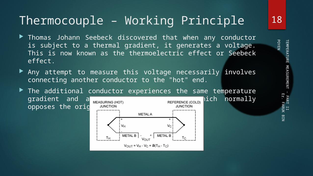
18Thermocouple – Working Principle Thomas Johann Seebeck discovered that when any conductor is subject to a thermal
gradient, it generates a voltage. This is now known as the thermoelectric effect or Seebeck effect.
Any attempt to measure this voltage necessarily involves connecting another conductor to the "hot" end.
The additional conductor experiences the same temperature gradient and also develops a voltage, which normally opposes the original.

TEMPERATURE M
EASUREMENT - PART II
Er. FARUK BIN POYEN
19Thermocouple – Working Principle Seebeck Effect: Energetic electrons at the hot end diffuse toward the cold end, pushing less
energetic electrons along with them, resulting in a higher static potential at the hot end relative to the cold end. The larger the temperature gradient, the larger is the potential difference.
Classical Configuration: To make the thermal effects measurable, two different metal
conductors are used. They must be chemically, electrically, and physically compatible. They produce different
electric potentials when subject to the same thermal gradient. In the classical configuration, the dissimilar thermocouple wires are welded together at the
measurement end (hot junction), and again at the reference end (cold junction), forming a loop. The hot junction assures that the potential at that point matches in the two metals. Immersing the
reference-end junction in an ice-water slurry assures that the temperature gradients are the same across both materials.
The ice-water slurry establishes a reference temperature at 0 ° C.

20Thermocouple – Cold Junction Compensation Thermocouples do require a stable voltage reference and some form of ice-point or
cold-junction compensation. Since the thermocouple measures temperature differentially, the cold-junction
temperature must be known in order to determine the actual temperature measured at the hot junction.
The output voltage of the thermocouple must also be compensated to account for the voltage created by the nonzero cold-junction temperature. This process is known as cold-junction compensation.
TEMPERATURE M
EASUREMENT - PART II
Er. FARUK BIN POYEN

TEMPERATURE M
EASUREMENT - PART II
Er. FARUK BIN POYEN
21Thermocouple - Features Advantages of Thermocouple:
Capable of being used to directly measure temperatures up to 2600°C Maybe brought into direct contact with the material being measured High resolution Rugged and reliable
Disadvantages of Thermocouple:
Non-linear
Complex operation
Two measurements required
Calibration required when in use

TEMPERATURE M
EASUREMENT - PART II
Er. FARUK BIN POYEN
22Thermocouple - Types There are several types of thermocouple based on the combination of metals/alloys for
the two junctions which are chosen on the merit of temperature range, sensitivity, inertness and magnetic effects.
Few types are J, K, T, N, E, B, R, S, M, C, D, G, P and W. Type J, K, T, & E are “Base Metal” thermocouples, the most common types of
thermocouples. Type R, S, and B thermocouples are “Noble Metal” thermocouples, which are used in
high temperature applications.

TEMPERATURE M
EASUREMENT - PART II
Er. FARUK BIN POYEN
23Thermocouple - TypesType Material Temperature Range Accuracy % Remark
J Iron – Constantan −40 °C to +750 °C +/- .75% Reliable, shorter lifespan, narrow range
K Nickel-Chromel/ Nickel-Alumel
−200 °C to +1350 °C +/- 0.75 Inexpensive, accurate, reliable and wide range
T Copper-Constantan −250 °C to 350 °C +/- 0.75 Stable, cryogenic measurement
E Nickel-Chromel/ Constantan
−270 °C to 870 °C +/- 0.50 Stronger signal and higher accuracy than k & J type
R Platinum-Rhodium (87:13)
−50 °C to 1600 °C +/- 0.25 High accuracy and stability. High resistance to oxidation and corrosion
B Platinum-Rhodium (70:30)
0 °C to 1700 °C +/- 0.5% Extreme high temperature
S Platinum-Rhodium (90:10)
−50 °C to 1600 °C +/- .25% Extreme high temperature. High resistance to oxidation and corrosion
M Nickel-Molybdenum Upper limit: 1400 °C +/- 0.75% Rare in use
N Nicrosil – Nisil −270 °C to 1300 °C +/- 0.75% Expensive

TEMPERATURE M
EASUREMENT - PART II
Er. FARUK BIN POYEN
24RTD – Thermocouple - ThermisterCriteria Thermocouple RTD Thermistor
Temp Range -267°C to 2316°C -240°C to 649°C -100°C to 500°C
Accuracy Good Best Good
Linearity Better Best Good
Sensitivity Good Better Best
Cost Best Good Better

TEMPERATURE M
EASUREMENT - PART II
Er. FARUK BIN POYEN
25Thermister Thermistors are thermally sensitive resistors whose prime function is to exhibit a large,
predictable and precise change in electrical resistance when subject to a corresponding change in body temperature.
These are semiconductors made from a specific mixture of pure oxides of nickel, manganese, copper, cobalt, iron, magnesium, titanium and other metals sintered at 982 °C.
Negative Temperature Coefficient (NTC) thermistors exhibit a decrease in electrical resistance when subject to an increase in body temperature and Positive Temperature Coefficient (PTC) thermistors exhibit an increase in electrical resistance when subject to an increase in body temperature.

TEMPERATURE M
EASUREMENT - PART II
Er. FARUK BIN POYEN
26Thermister Thermistors differ from resistance temperature detectors (RTDs) in that the material
used in a thermistor is generally a ceramic or polymer, while RTDs use pure metals. Range of Operation: −90 °C to 130 °C. Accuracy: ±0.1°C or ±0.2°C.

27Thermister - Principle The Steinhart-Hart equation gives the reciprocal of absolute temperature as a function of the
resistance of a thermistor. Using the Steinhart-Hart equation, we calculate the temperature of the thermistor from the measured resistance.
The Steinhardt-Hart equation is Where A, B and C are Steinhart–Hart parameters. R is the resistance and T is temperature; A
= 0.001284; B = 2.364x 10⁻⁴; C = 9.304x 10⁻⁸
The resistance value of a thermistor is given by the following equation
R= the resistance at temperature T in Kelvin (= °C +273) R Ref = the resistance at a reference temperature T0 in Kelvin
β = B-value specified for this thermistor T = Temperature under measurement, T Ref = Reference temperature
TEMPERATURE M
EASUREMENT - PART II
Er. FARUK BIN POYEN

TEMPERATURE M
EASUREMENT - PART II
Er. FARUK BIN POYEN
28Thermister - Principle To measure temperature with a thermistor, it is placed in the measuring environment and as
temperature increases, the resistance decreases (assuming NTC), and vice versa. The thermistor is placed in one leg of a Wheatstone bridge circuit and at balanced condition
with no change of temperature, the meter indicates zero. With changes in temperature, the Wheatstone bridge becomes unbalanced and an electric current
flows in the circuit.
In this bridge circuit, three resistors are constant, R a, R b, and R c, while the resistive sensor, RS, varies depending upon some physical variable - like temperature, light level, etc. That's where the thermistor can be used.
The thermistor can be placed anywhere in the bridge with three constant resistors, but different placements can produce different behaviour in the bridge. For example, different placements might cause the output voltage to go in different directions as the temperature changes.

TEMPERATURE M
EASUREMENT - PART II
Er. FARUK BIN POYEN
29Thermister - Configuration
Thermistors come in two-, three-, or four-wire configurations When there are more than two wires, the additional wires are solely used for
connecting to the excitation source. A three- or four-wire connection method places leads on a high-impedance path
through the measurement device, effectively attenuating error caused by lead-wire resistance (RL).

TEMPERATURE M
EASUREMENT - PART II
Er. FARUK BIN POYEN
30Thermister - Features Advantages of Thermistors:
Thermistors offer better accuracy in comparison to RTDs and thermocouples. Unlike RTDs and thermocouples, they are highly sensitive. They are smaller in size as compared to thermocouples. Thermistors provide faster response than RTDs. They offer high stability and brilliant repeatability. They are very reliable and convenient to use. Unlike thermocouples which provide millivolt outputs, use of thermistors result in
reasonable output voltages. Thermistors are particularly low cost and easily adaptable temperature sensors.
Disadvantages of Thermistors: Highly non-linear Limited temperature range

TEMPERATURE M
EASUREMENT - PART II
Er. FARUK BIN POYEN
31Thermopile A thermopile is an electronic device that converts thermal energy into electrical
energy. It is composed of several thermocouples connected usually in series or, less commonly, in parallel.
Thermopiles do not respond to absolute temperature, but generate an output voltage proportional to a local temperature difference or temperature gradient.
The output of a thermopile is usually in the range of tens to hundreds of millivolts. The output voltage of a thermopile is N times a single thermocouple, if N
thermocouples are connected in circuit.

TEMPERATURE M
EASUREMENT - PART II
Er. FARUK BIN POYEN
32Langmuir Probe A Langmuir probe is a device used to determine the electron temperature, electron
density, and electric potential of plasma. It works by inserting one or more electrodes into plasma, with a constant or time-
varying electric potential between the various electrodes or between them and the surrounding vessel. The measured currents and potentials in this system allow the determination of the physical properties of the plasma.
The guiding equation (Bohm criterion) for this device in its simplest form is given as
= ion speed; = Boltzman’s Constant; = charge state of the ions; = mass of ion
= electron temperature; = ion temperature; = adiabatic coefficients for the ions

TEMPERATURE M
EASUREMENT - PART II
Er. FARUK BIN POYEN
33Pyrometer Pyrometer comes from the Greek words meaning "fire" and "measurement". A pyrometer
is a type of remote-sensing thermometer used to measure the temperature of a surface. It is a device that from a distance determines the temperature of a surface from the spectrum of the thermal radiation it emits, a process known as pyrometry and sometimes radiometry.
Working Principle: A modern pyrometer has an optical system and a detector. The optical system focuses the
thermal radiation onto the detector. The output signal of the detector (temperature T) is related to the thermal radiation or irradiance j* of the target object through the Stefan–Boltzmann law, the constant of proportionality σ, called the Stefan-Boltzmann constant and the emissivity ε of the object.
This output is used to infer the object's temperature from a distance, with no need for the
pyrometer to be in thermal contact with the object. Pyrometry is a technique for determining a body’s temperature by measuring its
electromagnetic radiation.

TEMPERATURE M
EASUREMENT - PART II
Er. FARUK BIN POYEN
34Optical Pyrometer A brightness comparison is made to measure the temperature. As a measure of the
reference temperature, a colour change with the growth in temperature is taken. The device compares the brightness produced by the radiation of the object whose
temperature is to be measured, with that of a reference temperature. The reference temperature is produced by a lamp whose brightness can be adjusted till
its intensity becomes equal to the brightness of the source object. For an object, its light intensity always depends on the temperature of the object,
whatever may be its wavelength. After adjusting the temperature, the current passing through it is measured using a
multimeter, as its value will be proportional to the temperature of the source when calibrated.

TEMPERATURE M
EASUREMENT - PART II
Er. FARUK BIN POYEN
35Optical Pyrometer - Principle The radiation from the source is emitted and the optical objective lens captures it. The lens helps in focusing the thermal radiation on to the reference bulb. The observer
watches the process through the eye piece and corrects it in such a manner that the reference lamp filament has a sharp focus and the filament is super-imposed on the temperature source image.
The observer starts changing the rheostat values and the current in the reference lamp changes. This in turn, changes its intensity. This change in current can be observed in three different ways.
1. The filament is dark. That is, cooler than the temperature source.
2. Filament is bright. That is, hotter than the temperature source.
3. Filament disappears.
Thus, there is equal brightness between the filament and temperature source. At this time, the current that flows in the reference lamp is measured, as its value is a measure of the temperature of the radiated light in the temperature source, when calibrated.

TEMPERATURE M
EASUREMENT - PART II
Er. FARUK BIN POYEN
36Optical Pyrometer
TEMPERATURE M
EASUREMENT - PART II
Er. FARUK BIN POYEN
37Optical Pyrometer - Features Advantages of Optical Pyrometer are as follows:
Simple assembling of the device enables easy use of it. Provides a very high accuracy with +/-5 ° Celsius. There is no need of any direct body contact between the optical pyrometer and the object. As long as the size of the object, whose temperature is to be measured, fits with the size of
the optical pyrometer, the distance between both of them is not at all a problem. Thus, the device can be used for remote sensing.
This device can not only be used to measure the temperature, but can also be used to see the heat produced by the object/source. Thus, optical pyrometers can be used to measure and view wavelengths less than or equal to 0.65 microns.
Limitations of Optical Pyrometer are: The device is not useful for obtaining continuous values of temperatures at small intervals. As the measurement is based on the light intensity, the device can be used only in
applications with a minimum temperature of 700 ° Celsius.

TEMPERATURE M
EASUREMENT - PART II
Er. FARUK BIN POYEN
38Radiation Pyrometer The main theory behind a radiation pyrometer is that the temperature is
measured through the naturally emitted heat radiation by the body. This heat is known to be a function of its temperature. According to the
application of the device, the way in which the heat is measured can be summarized into two:
Total Radiation Pyrometer – In this method, the total heat emitted from the hot source is measured at all wavelengths.
Selective Radiation Pyrometer – In this method, the heat radiated from the hot source is measured at a given wavelength.

TEMPERATURE M
EASUREMENT - PART II
Er. FARUK BIN POYEN
39Radiation Pyrometer - Principle The radiation pyrometer has an optical system, including a lens, a mirror and an adjustable eye
piece. The heat energy emitted from the hot body is passed on to the optical lens, which collects it and
is focused on to the detector with the help of the mirror and eye piece arrangement. The detector may be a thermistor, resistance thermometer, thermocouple, photomultiplier tubes. The heat energy is converted to its corresponding electrical signal by the detector and is sent to
the output temperature display device.

TEMPERATURE M
EASUREMENT - PART II
Er. FARUK BIN POYEN
40Radiation Pyrometer - Classification The classification of radiation pyrometer is based on their focusing.
Fixed Focus Type Radiation Pyrometer Variable Focus Type Radiation Pyrometer

TEMPERATURE M
EASUREMENT - PART II
Er. FARUK BIN POYEN
41Fixed Focus Type Radiation Pyrometer It mainly consists of a long tube. A concave mirror is placed at the end of the tube as shown. A sensitive thermocouple is placed in front of the concave mirror in such a suitable
distance, that the heat radiation which enters the tube through narrow aperture at the front end of tube, is reflected by the concave mirror and is focused on the hot junction of the thermocouple.
Due to this fixed concave mirror, the radiation is always focused on the thermocouple irrespective of the distance between hot object and this instrument.
This is the reason why this instrument is called fixed focus type radiation pyrometer. The emf generated in the thermocouple is then measured with a help of a
galvanometer or millivoltmeter and this can be directly calibrated with temperature to get temperature reading readily.

TEMPERATURE M
EASUREMENT - PART II
Er. FARUK BIN POYEN
42

TEMPERATURE M
EASUREMENT - PART II
Er. FARUK BIN POYEN
43Variable Focus Type Radiation Pyrometer Unlike, fixed focus radiator pyrometer, here the position of the concave mirror can be
adjusted by adjusting knob attached to the instrument. Due to this adjustable concave mirror, the instrument is known as variable focus radiation
pyrometer. The concave mirror is made of highly polished steel. The heat rays from the targeted hot object are first received by the concave mirror then are
reflected on to the blackened thermo junction consisting of a very small copper or silver disc to which the wires forming the junction are soldered.
The visible image of the hot body can be seen on the small metallic disc attached to thermo-couple junction, through the eyepiece and the central hole of the main concave mirror.
The position of main concave mirror is adjusted until the focus coincides with the smaller metallic disc attached to the thermocouple junction.
The heating of the thermo junction due to this thermal image on the small metal disc produces an electro-motive force.
The temperature of the object can be measured by measuring this thermally generated emf by a sensitive galvanometer or millivoltmeter.

TEMPERATURE M
EASUREMENT - PART II
Er. FARUK BIN POYEN
44

TEMPERATURE M
EASUREMENT - PART II
Er. FARUK BIN POYEN
45Radiation Pyrometer - Features Sources of Errors in Radiation Pyrometers:
They are sensitive to any obstruction in the line of sight between meter and hot body. They are sensitive to emittance errors
Advantages of Radiation Pyrometer: Very high temperature measurement without direct contact Suitable for very high temperature measurement It can measure temperature of very small, very distinct and very far objects. It can be used to measure all temperatures of wavelengths between 0.70 microns and 20 microns They have high output and come at moderate cost.
Limitations of Radiation Pyrometers: Their scale is non – linear Error in measurement possible due to presence of intervening gases or vapours. Emissivity of target material affects measurement

TEMPERATURE M
EASUREMENT - PART II
Er. FARUK BIN POYEN
46Other Methods of Temperature Measurement Other Methods:
Quartz Thermometer Solid State Temperature Sensors Fibre optic Temperature Measurement System Ultrasonic Thermometers

TEMPERATURE M
EASUREMENT - PART II
Er. FARUK BIN POYEN
47Quartz Thermometer A piezo – electric crystal provides a highly accurate and sensitive method of
temperature measurement based on the changes in its resonant frequencies which is directly proportional to the temperature change.
Crystal is cut in the form of shear type LC cut, in which the change in resonant frequency is highly linear as well as repeatable.
The set up comprises a frequency counter. The fundamental frequency f 0 depends on the thickness of the crystal and can be
adjusted to give sensitivity of the order of 1000 Hz for a temperature change of 1 ° C. The temperature range is – 40 °C to 230 °C with a resolution of 0.001 °C.

TEMPERATURE M
EASUREMENT - PART II
Er. FARUK BIN POYEN
48Quartz Thermometer - Features The advantages of this thermometer are
Highly linear output with linearity error of ± 0.5 % of F. S Long term stability and reliability High resolution of the order of 0.001 °C Excellent repeatability in the range – 40 °C to 230 °C
The limitations are Low temperature range Crystals have strong cross – sensitivity for pressure change.

TEMPERATURE M
EASUREMENT - PART II
Er. FARUK BIN POYEN
49Solid State Temperature Sensors Common I.C devices like silicon diodes and transistors exhibit a stable and
reproducible response to temperature. When a PN junction is forward biased by a constant current source, its governing equation between current and voltage is as follows:
= Base Emitter Voltage; = Collector Current
K = Boltzmann Constant (1.38 * 10-23 J/K)
q = Electron charge (1.6 * 10-19 C); T = Absolute temperature (K) Generally, the term in the parenthesis in the equation is constant and the emitter base
voltage i.e. the output of the transducer becomes directly proportional to T which is the measured input.
Few IC temperature sensors are LM 35 (voltage output with scale factor is 0.01V/K) and AD 590 & OM 2628 (current output with scale factor of 1 µA/K).

TEMPERATURE M
EASUREMENT - PART II
Er. FARUK BIN POYEN
50Solid State Temperature Sensors The advantages of solid state temperature sensors are:
Inherent operating characteristics with excellent accuracy of the order of ± 1°C. They have high levels of output signal which is capable of direct indication
without any signal conditioning. The sensitivity of the silicon transistor within its usable range is – 55 °C to 150
°C is of the order of – 2 mV/°C.
The limitations are Limited temperature range Limited response characteristics due to their thermal mass.

TEMPERATURE M
EASUREMENT - PART II
Er. FARUK BIN POYEN
51Fibre Optic Temperature Measurement System The fibre optic assembly consists of a single fibre or several fibres bundled together. This fibre optic assembly gathers infrared radiation from the hot target and transmits it to an
infrared detector. The detector detects the radiated signal and converts it into a voltage, which is calibrated into
temperature units. Radiation proportional to temperature is conducted along an optical fibre to a sensor connected
to a measuring instrument. Variations in the basic principle make it possible to adopt this design to a variety of applications. A fibre optic thermometer depends on observation of brightness or on total radiation emitted
from the hot object. The measurement technique mostly often used is characterized by the distribution of energy by
wavelength and field of view. Fibres are sensitive only to the IR portion of the spectrum and filter out all other radiations.
Temperature ranges between 60 °C and 1100 °C.

TEMPERATURE M
EASUREMENT - PART II
Er. FARUK BIN POYEN
52Fibre Optic Temperature Measurement System The advantages of fibre optic thermometers are as follows:
Non – contact measuring system Small in size and rugged in design. It does not require line – of – sight observation. They are not affected by RF, microwave or EM fields or by shock or vibration. They cater wide range and response is fast They have the ability to look around opaque objects.
The limitation is unit measurement cost is high.

TEMPERATURE M
EASUREMENT - PART II
Er. FARUK BIN POYEN
53Ultrasonic Thermometers Ultrasonic thermometers are based on the effect of temperature on the velocity of
sound waves in the medium transmitting the sound waves. Temperature dependence of velocity in an ideal gas is expressed as v = sound velocity; = ratio of specific heats; R=gas constant per mole
T = absolute temperature; = molecular weight The temperature measurement can be made in gases, liquids or solids. The velocity of
sound increases in gases and decreases in liquids and solids as temperature rises.

TEMPERATURE M
EASUREMENT - PART II
Er. FARUK BIN POYEN
54Ultrasonic Thermometers The acoustic velocity can be detected by immersing a rod or wire into the fluid or by using the medium
itself as an acoustic conductor. This is done by measuring the time lags of the sound waves reflected from the consecutive indents.
The instrument is divided into three parts; (a) a thin – wire sensor, (b) a sound conductor and (c) a transmitting – receiving transducer.
The thin wire sensor is immersed into the fluid for detecting acoustic velocity. The lead – in – wire carries the pulse to the thin wire sensor made of a material suitable for the process medium and its temperature range.
Reflection from the beginning and the end of the thin – wire provides the time lapse information for temperature determination.
The transmitting transducer sends acoustic energy through the medium. Receiving transducers detect the energy and the time delay as measured by an intervalometer which
determines the velocity of sound and therefore the temperature of the process. When the medium is used as conductor of the ultrasonic pulse, the transducer is located within the vessel
or on its external shell. This configuration is useful when measuring the temperature of solids or extremely hot or corrosive
materials.

TEMPERATURE M
EASUREMENT - PART II
Er. FARUK BIN POYEN
55Ultrasonic Thermometers The advantages of ultrasonic thermometers are as follows:
They offer very high accuracy They offer very wide range extending from cryogenic range to plasma levels
(20000 °C) The limitations are:
They are very costly They require pressure correction and are unable to make point measurement. They require accurate determination of the ratio of specific heats The sensors have non – ideal gas behaviour

TEMPERATURE M
EASUREMENT - PART II
Er. FARUK BIN POYEN
56References: Chapter 13: Temperature Measurement, “Industrial Instrumentation and Control” by
S K Singh. Tata McGraw Hill, 3rd Edition. 2009, New Delhi. ISBN-13: 978-0-07-026222-5.
Chapter 11: Temperature Measurement, “Instrumentation, Measurement and Analysis”. 2nd Edition, B C Nakra, K K Chaudhry, Tata McGraw-Hill, New Delhi, 2005. ISBN: 0-07-048296-9.
Chapter 4: Temperature Sensors, “Fundamentals of Industrial Instrumentation”, 1st Edition, Alok Barua, Wiley India Pvt. Ltd. New Delhi, 2011. ISBN: 978-81-265-2882-0.
Chapter 4: Temperature Measurement, “Principles of Industrial Instrumentation”, 2nd Edition. D. Patranabis, Tata McGaw-Hill, New Delhi, 2004. ISBN: 0-07-462334-6.