teller screen project portfolio
TRANSCRIPT

The Need. The retail banking industry is changing rapidly. The rise of mobile banking has significantly reduced foot traffic into brick-and-mortar locations. Automated tellers are making basic transactions more efficient, reducing the need for on-site personnel. Drive-through windows are also in decline, adding to the total number of unused teller lines. Ten percent of our client’s banking centers have closed within the past two years, but remaining locations have barely begun to adapt to this paradigm shift. Some difficult decisions will have to be made about how to effectively down-size redundant retail banking space.
The Opportunity. Banks must now compete to maintain their market share through creative branding. Retail banks face a daunting and urgent challenge: What is the best way to update existing locations without expensive renovations?
The Solution. Our team developed this set of Teller Screen fixtures to promote branding continuity, clarify programmatic use of space, and act as a fresh coat of paint to make banking centers appear more vibrant. 3 of the 5 concepts shown above went into production in Fall, 2015. Of the 436 sites surveyed in 2016, 325 received Teller Screens.
u�es beuer ren ecre con,ecred
Ge� Tiore rewards
graphic designerJAC CORNELIUS
PROJECT PORTFOLIO
john.adams.cornelius@gmail 708.927.7797
INTENTTeller Screen
CONCEPTAcrylic Panels
Pictured (below + right) - Proposed counter “truss” mount for the Teller Screen fixture. Similar renderings are reviewed by the client for approval and used by vendors as installation guides
Purpose. These fixtures block unused portions of a teller line or drive-up window with a branded element that is complimentary to the existing banking center environment.
Structure. Fixtures are composed of three vertical poles, mounted at two points, and spanned by branded acrylic panels.
Benefit. We engineered the fixture so Point-of-Sale panels can be added to the framework and updated with new graphics to reflect current promotions.
Mount DetailDrop - CeilingFreestandingCeiling
Soffit
Counter
80TFASSEMBLYSPECS MODEL PLACEMENT CONTENTS
Measure available distance from the floor to the ceiling / soffit in the proposed installation area. Unless the full height of the poles is required, cut all poles down to desired length.
Install FLOOR MOUNT using appropriate anchor / fastener (not included). Note: Align the direction of the threaded holed with the acrylic panels. Attach the next floor mount 22” O.C.
Tilt ROUND REED and slide the bottom over FLOOR MOUNT. Line up holes in ROUND REED with threaded holes in the FLOOR MOUNT.
Push CEILING PLATE from REED PLATE until the CEILING PLATE contacts the ceiling. Make sure the ROUND REED is straight and level. Mark holes and install anchors in ceiling. Line up CEILING PLATE holes, level the ROUND REED, and then tighten the THREADED ROD.
Insert ADJUSTABLE CEILING MOUNT into top of ROUND REED as shown.
Install included M8 SCREWS into FLOOR MOUNT.
Teller Screen - Floor to Ceiling Mount
1. 2. 3.
4. 5. 6.
Name of Branch:
Address:
Bank Manager/Contact: Telephone Number:
FLOOR TO CEILING(MOUNT WITH SCREWS)DA BCOUNTER TO
DRYWALL/MILLWORK(MOUNT WITH SCREWS)
TELLER LINE SCREEN SITE SURVEY
50 GREENE STREET I NEW YORK, NY 10013 I T 212.924.8713 I F 212.924.8674 I WWW.ALU.COM
COUNTER TO ACRYLIC/GLASS(MOUNT WITH ADHESIVE)
C COUNTER TO CEILING
Name of Surveyor:
Email of Surveyor:
Telephone of Surveyor:
1. CHOOSE EITHER SET-UP A, B, C OR D: A= FLOOR TO CEILING, B= COUNTER TO MILLWORK WALL, C= WALL TO ACRYLIC/GLASS WINDOW/WALL OR D= COUNTER TO CEILING (NEXT PAGE).2. FILL-IN REQUIRED DIMENSIONS.3. CHOOSE QUANTITY OF SET-UPS (SET-UPS ARE BY PAIRS).4. FILL-IN CONTACT INFORMATION.
CEILING CEILING
COUNTER COUNTERCOUNTER
B OR C
QUANTITYOF UNITS
QUANTITYOF UNITS
48”(ONE UNIT)QUANTITY
OF UNITS
48”(ONE UNIT)
46.25”(ONE UNIT)
TOTAL WIDTH TOBE COVERED BYSCREEN UNITS:
CEILING HEIGHTABOVE FINISHEDFLOOR =
CEILING HEIGHTABOVE COUNTER =
COUNTER HEIGHTABOVE FINISHEDFLOOR =
POLE HEIGHTABOVE COUNTER =
COUNTER HEIGHTABOVE FINISHEDFLOOR =
TOTAL WIDTH TOBE COVERED BYSCREEN UNITS =
TOTAL WIDTH TOBE COVERED BYSCREEN UNITS =
COUNTER
DIMENSION OF LENGTHOF WALL MOUNT(CUT DURING INSTALLATION) =
2 3/16”
CONCEPT
graphic designerJAC CORNELIUS
john.adams.cornelius@gmail 708.927.7797
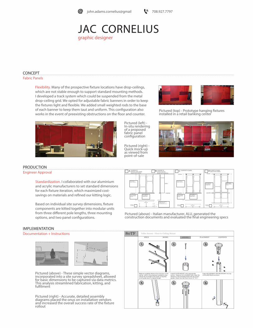
Fabric Panels
Standardization. I collaborated with our aluminium and acrylic manufacturers to set standard dimensions for each fixture iteration, which maximized cost- savings on materials and refined our kitting logic.
Based on individual site survey dimensions, fixture components are kitted together into modular units from three different pole lengths, three mounting options, and two panel configurations.
PRODUCTIONEngineer Approval
Flexibility. Many of the prospective fixture locations have drop-ceilings, which are not stable enough to support standard mounting methods. I developed a track system which could be suspended from the metal drop-ceiling grid. We opted for adjustable fabric banners in order to keep the fixtures light and flexible. We added small weighted rods to the base of each banner to keep them taut and uniform. This configuration also works in the event of preexisting obstructions on the floor and counter.
Pictured (left) -In-situ rendering of a proposed fabric panel configuration
Pictured (right) -Quick mock-up as viewed from point-of-sale
Pictured (top) - Prototype hanging fixtures installed in a retail banking center
IMPLEMENTATIONDocumentation + Instructions
Pictured (above) - These simple vector diagrams, incorporated into a site survey spreadsheet, allowed for basic dimensions to be captured via data metrics. This analysis streamlined fabrication, kitting, and fulfilment
Pictured (right) - Accurate, detailed assembly diagrams placed the onus on installation vendors and increased the overall success rate of the fixture rollout
Pictured (above) - Italian manufacturer, ALU, generated the construction documents and evaluated the final engineering specs

graphic designerJAC CORNELIUS
ELISA WINTER-HOLBEN
ALU
ACRYLIC DESIGN ASSOCIATES
WINTER - HOLBEN ARCHITECTURE
ALU
ACRYLIC DESIGN ASSOCIATES
CREATIVE DIRECTOR
MANUFACTURER
MANUFACTURER
207.994.3104
763.559.8395
+0039 0424 516816
email: [email protected]
http://www.winterholben.com
www.alu.com
http://www.acrylicdesign.com
CONTACT
CONTACT
CONTACT
Phone:
Phone:
Phone:
E-mail:
E-mail:
E-mail:
Web:
Web:Web:
Web:
7 Wallingford Square, THINKYARD Unit 2099Kittery, ME 03904
Via del Commercio n. 22, Romano D’ezzelino (VI), Italy
6050 Nathan Lane, Minneapolis, MN 55442
Elisa created the initial product design. She was the driving force behind this concept becoming a production fixture.
ADA assisted in the production of prototypes and continues to manufacture all acrylic components for corresponding fixtures.
All images contained in this portfolio were created by Jac Cornelius unless otherwise indicated.
ALU created final construction documents and continues to fabricate all metal components for corresponding fixtures.
CREDITS
john.adams.cornelius@gmail 708.927.7797
GREG NELSON
JOHN RYAN PERFORMANCE
SENIOR PROJECT MANAGER
CONTACT
Phone:E-mail:Web:
1350 Lagoon Ave, Suite 800Minneapolis, MN 55408
Greg Nelson coordinated efforts between vendors. He delegated work internally and created production schedules.