telemeter, telecontrol and data transmission radio ... · pdf filewe hope that this standard...
TRANSCRIPT
Association of Radio Industries and Businesses (ARIB)
VERSION 1.1
ARIB STD-T67
TELEMETER, TELECONTROLAND DATA TRANSMISSION
RADIO EQUIPMENT FOR SPECIFIEDLOW-POWER RADIO STATION
ARIB STD-T67
ARIB STANDARD
Version 1.0Version 1.1
JulyNovember
25th30th
20002005
ENGLISH TRANSLATION

General Notes to the English translation of ARIB Standards and Technical Reports
1. The copyright of this document is ascribed to the Association of Radio Industries and Businesses (ARIB).
2. All rights reserved. No part of this document may be reproduced, stored in a retrieval system, or transmitted, in any form or by any means, without the prior written permission of ARIB.
3. The ARIB Standards and ARIB Technical Reports are usually written in Japanese and approved by the ARIB Standard Assembly. This document is a translation into English of the approved document for the purpose of convenience of users. If there are any discrepancies in the content, expressions, etc., between the Japanese original and this translated document, the Japanese original shall prevail.1
4. The establishment, revision and abolishment of ARIB Standards and Technical Reports are approved at the ARIB Standard Assembly, which meets several times a year. Approved ARIB Standards and Technical Reports, in their original language, are made publicly available in hard copy, CDs or through web posting, generally in about one month after the date of approval. The original document of this translation may have been further revised and therefore users are encouraged to check the latest version at an appropriate page under the following URL:
http://www.arib.or.jp/english/index.html
1 There are a lot of difference between version 1.0 and the latest version of English translation of ARIB STD-T67. English expression had been just changed for the matter of English expression except for the changes which appear on the table of Standard revisions.
ARIB STD-T67
Introduction
The Association of Radio Industries and Businesses (ARIB) establishes basic requirements such as standard specifications for radio equipment relating to each system that uses radio waves and makes them 'standard' with the participation of radio equipment manufacturers, operators, broadcasters and users.
This standard is a private one that is based on two standards: a national technical standard for the purpose of effective use of radio frequencies and avoidance of interference among users, and a private optional standard for the purpose of convenience of radio equipment manufacturers and users.
This standard is established principally for “Telemeter, Telecontrol and Data Transmission Radio Equipment for Specified Low-Power Radio Station” through the integration of the following standards: “Data Transmission Radio Equipment (RCR STD-2),” “Telemeter/Telecontrol Radio Equipment (RCR STD-4),” “Telemeter/Telecontrol Radio Equipment for Specified Low-Power Radio Station (RCR STD-16),” “400 MHz Band Data Transmission Radio Equipment for Specified Low-Power Radio Station (RCR STD-17),” and “1,200 MHz Band Data Transmission Radio Equipment for Specified Low-Power Radio Station (RCR STD-18).” In order to ensure fairness, impartiality, and openness among all parties involved, during the drafting stages, we invited radio equipment manufacturers, telecommunications operators, broadcasting companies, test organizations, and users, both domestic and foreign, to participate openly in the activities of the Standard Assembly so as to develop standards with the total agreement of all parties involved. We hope that this standard will aid all parties involved, including radio equipment manufacturers, test organizations, users, and other interested parties.


ARIB STD-T67
- i -
Contents
Introduction
Chapter 1. General..................................................................................................................................... 1
1.1 Overview ............................................................................................................................................... 1 1.2 Scope of application .............................................................................................................................. 1 1.3 Definitions, terminology ....................................................................................................................... 1
Chapter 2. Standard Systems.................................................................................................................... 2
2.1 Configurations of Standard System....................................................................................................... 2 2.2 Operation forms of standard system...................................................................................................... 3
(1) Basic 1:1 type.................................................................................................................................. 3 (2) Basic 1:N type................................................................................................................................. 3 (3) Basic M: N type .............................................................................................................................. 3 (4) Extended-area 1:1 and 1:N types .................................................................................................... 3 (5) Extended-area M: N type ................................................................................................................ 3
Chapter 3. Technical Conditions of Radio Equipment........................................................................... 4
3.1 General conditions................................................................................................................................. 4 (1) Communication method .................................................................................................................. 4 (2) Communication contents................................................................................................................. 4 (3) Emission classes.............................................................................................................................. 4 (4) Operating frequencies ..................................................................................................................... 4 (5) Frequency-switching method .......................................................................................................... 4 (6) Ambient conditions ......................................................................................................................... 4
3.2 Transmitter .......................................................................................................................................... 10 (1) Antenna power .............................................................................................................................. 10 (2) Tolerances for antenna power ....................................................................................................... 10 (3) Oscillation method ........................................................................................................................ 10 (4) Frequency tolerance .................................................................................................................... 10 (5) Modulation method ....................................................................................................................... 10 (6) Frequency deviation ...................................................................................................................... 10 (7) Modulation rate ............................................................................................................................. 10 (8) Coding type ................................................................................................................................... 10 (9) Adjacent-channel leakage power .................................................................................................. 10 (10) Permissible value for occupied bandwidth.................................................................................. 11 (11) Permissible value of intensity of spurious emission or unwanted emission................................ 11 (12) Transmission rise time and fall time ........................................................................................... 12
3.3 Receiver ............................................................................................................................................. 12 (1) Encoding reference sensitivity ...................................................................................................... 12 (2) Spurious response at effective selectivity ..................................................................................... 12 (3) Adjacent-channel selectivity at effective selectivity ..................................................................... 12 (4) Frequency drift of the local oscillator ........................................................................................... 12 (5) Limit on Secondary Radiated Emissions ...................................................................................... 12
3.4 Controller ............................................................................................................................................ 12 (1) Interference prevention function ................................................................................................... 12 (2) Identification of the opposite party of communication ................................................................. 13 (3) Transmission time restricting device............................................................................................. 13 (4) Carrier sensing device ................................................................................................................... 15 (5) Examples of channel connection procedures ................................................................................ 15

ARIB STD-T67
- ii -
3.5 Antennas.............................................................................................................................................. 20 (1) Antenna structure .......................................................................................................................... 20 (2) Antenna gain ................................................................................................................................. 20 (3) Division in the use of antennas ..................................................................................................... 20
3.6 Others .............................................................................................................................................. 20 (1) Cabinet .......................................................................................................................................... 20 (2) Mark of technical regulations conformity certification................................................................. 20 (3) Interface with associated units ...................................................................................................... 20 (4) Safety and reliability ..................................................................................................................... 20
Chapter 4. Connection to Telecommunications Circuit Facilities ....................................................... 21
(1) Identification sign ......................................................................................................................... 21 (2) Conditions for interfacing with telecommunications circuit equipment ....................................... 21 (3) Establishment of a communication channel.................................................................................. 21 (4) Cabinet .......................................................................................................................................... 21 (5) Mark of technical conditions compliance approval of terminal equipment .................................. 20
Chapter 5. Measurement Methods ......................................................................................................... 22
Reference Test items in relation to specified radio equipment ............................................................ 23
Reference Precautions on the use of the 1,200MHz Band .................................................................... 24
Table of Standard Revisions

ARIB STD-T67
-1-
Chapter 1. General
1.1 Overview
Among the specified low-power radio stations defined in Article 6 of the Regulations for Enforcement of the Radio Law, this standard provides for telemetry radio equipment designed to automatically indicate and/or record the results obtained by measuring instruments located remotely by means of radio waves; telecontrol radio equipment for the transmission of signals to activate, change, or deactivate the functions of devices located remotely by means of radio waves; and data transmission radio equipment intended for the transmission of information to be processed primarily by machines, or of previously processed information.
1.2 Scope of application
Telemetry, telecontrol and data transmission radio stations are composed of radio equipment and associated equipment (including that connected to telecommunications circuit facilities), as illustrated in Figure 1.1. This standard provides for that radio equipment.
Figure 1.1 Configuration of Telemetry, Telecontrol and Data Transmission Radio Equipment 1.3 Conforming documents
In this standard, “Enforcement” refers to Regulations for Enforcement of the Radio Law, “Equipment” refers to Ordinance Regulating Radio Equipment, “Technical Conformity” refers to Ordinance Concerning Technical Regulations Conformity Certification etc. of Specified Radio Equipment, “Terminal” refers to Ordinance Concerning Terminal Facilities etc., “Terminal Technical Approval” refers to Rules Concerning the Technical Conditions Compliance Approval etc. for Terminal Equipment, and “Notification” refers to a Notification of the Ministry of Posts and Telecommunications if issued in 2000 or earlier, and a Notification of the Ministry of Internal Affairs and Communications if issued in 2001 or later.
Associated equipment Transmitter
Receiver
Controller • Interference
prevention function• Transmission time
restriction device • Carrier sensing
device
Radio equipment
Scope of application

ARIB STD-T67
-2-
Chapter 2. Standard Systems
2.1 Configurations of Standard System
Figure 2.1 represents the configurations of standard system, which are divided into the basic type and the extended-area type.
Figure 2.1 Configurations of Standard System

ARIB STD-T67
-3-
2.2 Operation forms of standard system
The standard system of the telemetry, telecontrol and data transmission radio equipment is operated as described below.
(1) Basic 1:1 type
The basic 1:1 type enables one-on-one basis in the point to point communication. a. For one-way communication and simplex operation, the frequencies defined for such
communication methods shall be used. b. For duplex operation, the paired frequencies defined for such methods or semi-duplex operation
shall be used.
(2) Basic 1:N type The basic 1:N type allows multiple mobile stations to communicate with one unit of base-station radio equipment in the point to multi-point communication. In either communication method, the downlink lines to multiple mobile stations use the same frequency, while the following frequencies are available for the uplink lines from the mobile stations: a. For simplex operation and broadcast communication, the frequencies defined for one-way
communication or simplex operation shall be used (if a simplex operation employs a different transmission frequency from that of the base station, the mobile stations shall be equipped with a receiver capable of receiving that transmission frequency to perform carrier sensing).
b. For duplex operation, frequencies paired to the base station shall be used.
(3) Basic M: N type The basic M: N type is a centralized base type composed of multiple units of radio equipment that are installed at the same location and are controlled by one unit of associated equipment. It allows simultaneous communication with multiple mobile stations, and also enables the mobile stations to communication among themselves through the repetition by the centralized-base-type radio equipment.
(4) Extended-area 1:1 and 1:N types In the extended-area type, a repeater station is provided for the purpose of extending the service area. This type is subdivided into the “Two-frequency simplex repetition type,” which consists of one unit of duplex operation radio equipment, and the “Four-frequency duplex repetition type,” which is composed of two units of duplex operation radio equipment. The two-frequency simplex repetition type is a two-frequency simplex operation that uses the two frequencies of a duplex operation and enables semi-duplex operation between the base station and a mobile station, and also between mobile stations. The four-frequency duplex repetition type uses the four frequencies of two different duplex operation in communications between the base station and the repeater station and between the repeater station and the mobile stations, thereby enabling simplex or duplex operation. However, if automatic control is adopted with loopback from R2, communication can also be held between the mobile stations by the simplex operation. It is necessary that the repetition is carried out on the baseband level, and the repeater station performs carrier sensing prior to the repetition.
(5) Extended-area M: N type Unlike the system described in Item (3) above, which is of the centralized base type that places multiple units of radio equipment in a single centralized location, the extended-area M: N type is a decentralized base type in which multiple units of radio equipment are installed in a scattered fashion. Other than the layout of the base stations, the rest of operation is exactly the same as in Item (3).
ARIB STD-T67
-4-
Chapter 3. Technical Conditions of Radio Equipment
3.1 General conditions
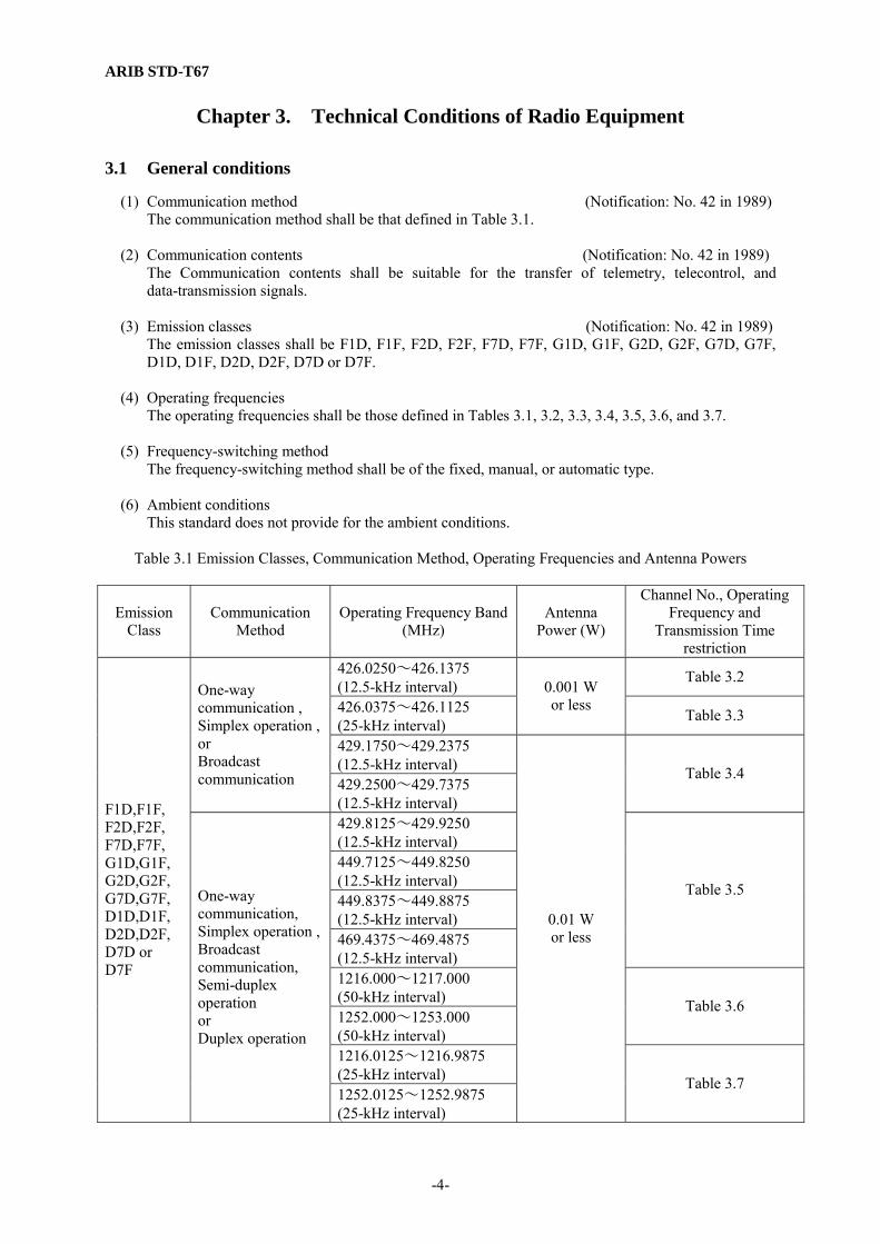
(1) Communication method (Notification: No. 42 in 1989) The communication method shall be that defined in Table 3.1.
(2) Communication contents (Notification: No. 42 in 1989) The Communication contents shall be suitable for the transfer of telemetry, telecontrol, and data-transmission signals.
(3) Emission classes (Notification: No. 42 in 1989) The emission classes shall be F1D, F1F, F2D, F2F, F7D, F7F, G1D, G1F, G2D, G2F, G7D, G7F, D1D, D1F, D2D, D2F, D7D or D7F.
(4) Operating frequencies The operating frequencies shall be those defined in Tables 3.1, 3.2, 3.3, 3.4, 3.5, 3.6, and 3.7.
(5) Frequency-switching method
The frequency-switching method shall be of the fixed, manual, or automatic type.
(6) Ambient conditions This standard does not provide for the ambient conditions.
Table 3.1 Emission Classes, Communication Method, Operating Frequencies and Antenna Powers
Emission Class
Communication Method
Operating Frequency Band (MHz)
Antenna Power (W)
Channel No., Operating Frequency and
Transmission Time restriction
426.0250~426.1375 (12.5-kHz interval)
Table 3.2
426.0375~426.1125 (25-kHz interval)
0.001 W or less
Table 3.3
429.1750~429.2375 (12.5-kHz interval)
One-way communication , Simplex operation , or Broadcast communication 429.2500~429.7375
(12.5-kHz interval)
Table 3.4
429.8125~429.9250 (12.5-kHz interval) 449.7125~449.8250 (12.5-kHz interval) 449.8375~449.8875 (12.5-kHz interval) 469.4375~469.4875 (12.5-kHz interval)
Table 3.5
1216.000~1217.000 (50-kHz interval) 1252.000~1253.000 (50-kHz interval)
Table 3.6
1216.0125~1216.9875 (25-kHz interval)
F1D,F1F, F2D,F2F, F7D,F7F, G1D,G1F, G2D,G2F, G7D,G7F, D1D,D1F, D2D,D2F, D7D or D7F
One-way communication, Simplex operation , Broadcast communication, Semi-duplex operation or Duplex operation
1252.0125~1252.9875 (25-kHz interval)
0.01 W or less
Table 3.7
ARIB STD-T67
-5-
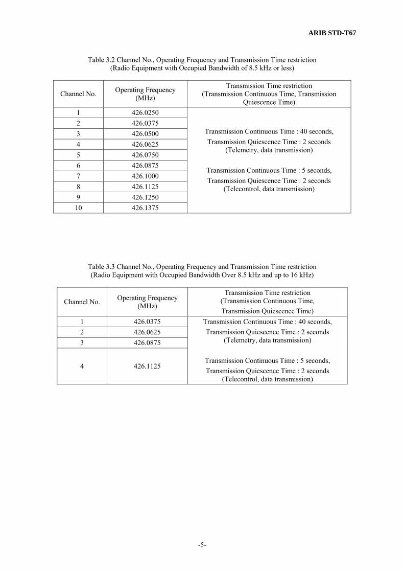
Table 3.2 Channel No., Operating Frequency and Transmission Time restriction
(Radio Equipment with Occupied Bandwidth of 8.5 kHz or less)
Channel No. Operating Frequency (MHz)
Transmission Time restriction (Transmission Continuous Time, Transmission
Quiescence Time) 1 426.0250 2 426.0375 3 426.0500 4 426.0625 5 426.0750 6 426.0875 7 426.1000 8 426.1125 9 426.1250 10 426.1375
Transmission Continuous Time : 40 seconds, Transmission Quiescence Time : 2 seconds
(Telemetry, data transmission)
Transmission Continuous Time : 5 seconds, Transmission Quiescence Time : 2 seconds
(Telecontrol, data transmission)
Table 3.3 Channel No., Operating Frequency and Transmission Time restriction (Radio Equipment with Occupied Bandwidth Over 8.5 kHz and up to 16 kHz)
Channel No. Operating Frequency (MHz)
Transmission Time restriction (Transmission Continuous Time, Transmission Quiescence Time)
1 426.0375 2 426.0625 3 426.0875
4 426.1125
Transmission Continuous Time : 40 seconds, Transmission Quiescence Time : 2 seconds
(Telemetry, data transmission)
Transmission Continuous Time : 5 seconds, Transmission Quiescence Time : 2 seconds
(Telecontrol, data transmission)

ARIB STD-T67
-6-
Table 3.4 Channel No., Operating Frequency and Transmission Time restriction (Radio Equipment with Occupied Bandwidth of 8.5 kHz or less)
Channel No. Operating Frequency (MHz)
Transmission Time restriction (Transmission Continuous Time, Transmission Quiescence Time)
1 429.1750 2 429.1875 3 429.2000 4 429.2125 5 429.2250 6 429.2375
Transmission Continuous Time : 40 seconds, Transmission Quiescence Time : 2 seconds
7 429.2500 8 429.2625 9 429.2750 10 429.2875 11 429.3000 12 429.3125 13 429.3250 14 429.3375 15 429.3500 16 429.3625 17 429.3750 18 429.3875 19 429.4000 20 429.4125 21 429.4250 22 429.4375 23 429.4500 24 429.4625 25 429.4750 26 429.4875 27 429.5000 28 429.5125 29 429.5250 30 429.5375 31 429.5500 32 429.5625 33 429.5750 34 429.5875 35 429.6000 36 429.6125 37 429.6250 38 429.6375 39 429.6500 40 429.6625 41 429.6750 42 429.6875 43 429.7000 44 429.7125 45 429.7250 46 429.7375
Continuous transmission (Intermittent communication possible)

ARIB STD-T67
-7-
Table 3.5 Channel No., Operating Frequency and Transmission Time restriction (Radio Equipment with Occupied Bandwidth of 8.5 kHz or less)
Channel No. Operating Frequency (MHz)
Transmission Time restriction (Transmission Continuous Time, Transmission Quiescence Time)
1 429.8125 449.7125 2 429.8250 449.7250 3 429.8375 449.7375 4 429.8500 449.7500 5 429.8625 449.7625 6 429.8750 449.7750 7 429.8875 449.7875 8 429.9000 449.8000 9 429.9125 449.8125
Transmission Continuous Time : 40 seconds, Transmission Quiescence Time : 2 seconds
10 429.9250 449.8250
Transmission Continuous Time : 0.2 seconds, Transmission Quiescence Time : 2 seconds
11 449.8375 469.4375 12 449.8500 469.4500 13 449.8625 469.4625 14 449.8750 469.4750
Transmission Continuous Time : 40 seconds, Transmission Quiescence Time : 2 seconds
15
449.8875 469.4875 Transmission Continuous Time : 0.2 seconds, Transmission Quiescence Time : 2 seconds
Note 1: The four frequencies of Channel No. 10 and 15 shall be used for the frequency control
channels. Note 2: For the data channels of the duplex or semi-duplex operation, the paired frequencies of the
same channel No. shall be used, excluding the four frequencies of Channel No. 10 and 15.
ARIB STD-T67
-8-
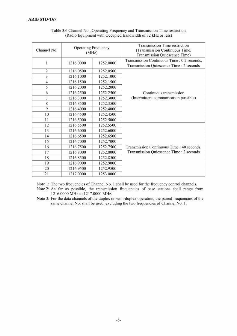
Table 3.6 Channel No., Operating Frequency and Transmission Time restriction (Radio Equipment with Occupied Bandwidth of 32 kHz or less)
Channel No. Operating Frequency (MHz)
Transmission Time restriction (Transmission Continuous Time, Transmission Quiescence Time)
1 1216.0000 1252.0000 Transmission Continuous Time : 0.2 seconds,Transmission Quiescence Time : 2 seconds
2 1216.0500 1252.0500 3 1216.1000 1252.1000 4 1216.1500 1252.1500 5 1216.2000 1252.2000 6 1216.2500 1252.2500 7 1216.3000 1252.3000 8 1216.3500 1252.3500 9 1216.4000 1252.4000 10 1216.4500 1252.4500 11 1216.5000 1252.5000
Continuous transmission (Intermittent communication possible)
12 1216.5500 1252.5500 13 1216.6000 1252.6000 14 1216.6500 1252.6500 15 1216.7000 1252.7000 16 1216.7500 1252.7500 17 1216.8000 1252.8000 18 1216.8500 1252.8500 19 1216.9000 1252.9000 20 1216.9500 1252.9500 21 1217.0000 1253.0000
Transmission Continuous Time : 40 seconds, Transmission Quiescence Time : 2 seconds
Note 1: The two frequencies of Channel No. 1 shall be used for the frequency control channels. Note 2: As far as possible, the transmission frequencies of base stations shall range from
1216.0000 MHz to 1217.0000 MHz. Note 3: For the data channels of the duplex or semi-duplex operation, the paired frequencies of the
same channel No. shall be used, excluding the two frequencies of Channel No. 1.

ARIB STD-T67
-9-
Table 3.7 Channel No., Operating Frequency and Transmission Time restriction (Radio Equipment with Occupied Bandwidth of 16 kHz or less)
Channel No. Operating Frequency (MHz)
Transmission Time restriction (Transmission Continuous Time, Transmission Quiescence Time)
1 1216.0125 1252.0125 Transmission Continuous Time : 0.2 seconds,Transmission Quiescence Time : 2 seconds
2 1216.0375 1252.0375 3 1216.0625 1252.0625 4 1216.0875 1252.0875 5 1216.1125 1252.1125 6 1216.1375 1252.1375 7 1216.1625 1252.1625 8 1216.1875 1252.1875 9 1216.2125 1252.2125 10 1216.2375 1252.2375 11 1216.2625 1252.2625 12 1216.2875 1252.2875 13 1216.3125 1252.3125 14 1216.3375 1252.3375 15 1216.3625 1252.3625 16 1216.3875 1252.3875 17 1216.4125 1252.4125 18 1216.4375 1252.4375 19 1216.4625 1252.4625 20 1216.4875 1252.4875
Continuous transmission (Intermittent communication possible)
21 1216.5125 1252.5125 Transmission Continuous Time : 0.2 seconds,Transmission Quiescence Time : 2 seconds
22 1216.5375 1252.5375 23 1216.5625 1252.5625 24 1216.5875 1252.5875 25 1216.6125 1252.6125 26 1216.6375 1252.6375 27 1216.6625 1252.6625 28 1216.6875 1252.6875 29 1216.7125 1252.7125 30 1216.7375 1252.7375 31 1216.7625 1252.7625 32 1216.7875 1252.7875 33 1216.8125 1252.8125 34 1216.8375 1252.8375 35 1216.8625 1252.8625 36 1216.8875 1252.8875 37 1216.9125 1252.9125 38 1216.9375 1252.9375 39 1216.9625 1252.9625 40 1216.9875 1252.9875
Transmission Continuous Time : 40 seconds, Transmission Quiescence Time : 2 seconds
Note 1: The four frequencies of Channel No.1 and 21 shall be used for the frequency control
channels. Note 2: As far as possible, the transmission frequencies of base stations shall range from
1216.0125 MHz to 1216.9875 MHz. Note 3: For the data channels of the duplex or semi-duplex operation, the paired frequencies of the
same channel No. shall be used, excluding the four frequencies of Channel No. 1 and 21.

ARIB STD-T67
-10-
3.2 Transmitter
(1) Antenna power (Notification: No. 42 in 1989) The antenna power (the specified or rated power that is supplied from the transmitter to the feeder of an antenna system in normal operation and is averaged over a sufficiently long period of time compared to the cycle of the lowest frequency) shall be 0.01 W or less. However, for transmission units using a frequency between 426.025 MHz and 426.1375 MHz, the antenna power shall be 0.001 W or less.
(2) Tolerances for antenna power (Equipment: Article 14) The tolerances for antenna power (the maximum allowable deviation from the specified or rated antenna power) shall be +20% to -50%.
(3) Oscillation method (Equipment: Article 49.14) The oscillation method shall be the crystal oscillation method or the synthesizer method which uses crystal oscillation to control the oscillation frequency.
(4) Frequency tolerance (Equipment: Article 5) (Notification: No. 50 in 1989)
The frequency tolerance (the maximum allowable deviation of the center frequency of the band occupied by emission from the allocated frequency) shall be ±4 x 10⁻⁶, measured as an average value, with respect to the standard coded test signal (a signal of repetitive binary pseudo-noise with a code length of 511 bits) taken as the modulating input signal. However, for transmitters operating in the 1,200-MHz band with channel interval of 25 kHz, the frequency tolerance shall be ±3 x 10⁻⁶. For transmitters having a function for sending non-modulated carriers, the frequency tolerance may be measured on those carriers.
(5) Modulation method The modulation method shall be one that conforms to the emission classes specified in 3.1 (3).
(6) Frequency deviation This standard does not provide frequency deviation.
(7) Modulation rate This standard does not provide modulation rates.
(8) Coding type This standard does not provide coding type.
(9) Adjacent-channel leakage power (Equipment: Article 49.14) (Notification: No. 49 in 1989)
a. As for the adjacent-channel leakage power in the 400MHz band (the power radiated in a certain band of the adjacent channel separated from the carrier frequency at the specified frequency interval), the power radiated into the ±4.25 kHz band of the frequency 12.5 kHz distant from the carrier frequency shall be lower than the carrier power by 40 dB or more, when modulation is performed using the standard coded test signal at the same transmission speed as that of the modulation signal. However, for transmitters that emit radio waves in an occupied bandwidth over 8.5 kHz and up to 16 kHz, the power radiated into the ±8 kHz band of the frequency 25 kHz distant from the carrier frequency shall be lower than the carrier power by 40 dB or more.
b. As for the adjacent-channel leakage power in the 1,200MHz band, the power radiated into the
±16 kHz band of the frequency 50 kHz distant from the carrier frequency shall be lower than the carrier power by 40 dB or more for transmitters with channel interval of 50 kHz, and the power radiated into the ±8 kHz band of the frequency 25 kHz distant from the carrier frequency shall be lower than the carrier power by 40 dB or more for transmitters with channel interval of 25 kHz when, in both cases, the modulation is performed using the standard coded test signal at the same

ARIB STD-T67
-11-
transmission speed as that of the modulation signal.
(10) Permissible value for occupied bandwidth (Equipment: Article 6) (Notification: No. 51 in 1989)
a. The permissible value for a occupied bandwidth (the bandwidth such that the mean powers radiated below its lower-frequency limit and above its upper-frequency limit are each equal to 0.5% of the total mean power radiated by a given emission) in the 400MHz band shall be 8.5 kHz when the modulation is performed using the standard coded test signal at the same transmission speed as that of the modulation signal. However, for transmitters emitting radio waves in an occupied bandwidth over 8.5 kHz and up to 16 kHz, the value shall be 16 kHz.
b. The permissible value for a occupied bandwidth in the 1,200MHz band shall be 32 kHz for transmitters with channel interval of 50 kHz, and 16 kHz for those with channel interval of 25 kHz when, in both cases, the modulation is performed using the standard coded test signal at the same transmission speed as that of the modulation signal.
(11) Permissible value of intensity of spurious emission or unwanted emission
a. Definitions (Enforcement: Article 2.1) (Equipment: Table 3)
“Spurious emission” refers to the emission on a frequency or frequencies which are outside the permitted bandwidth and the level of which may be reduced without affecting the corresponding transmission of information, including a high-harmonic emission, a low-harmonic emission, a parasitic emission and an intermodulation product but excluding an out-of-band emission. (Enforcement: Article 2.1.63) “Out-of-band emission” refers to the emission which results from the modulation process on a frequency or frequencies outside the permitted bandwidth. (Enforcement: Article 2.1.63-2) “Unwanted emission” refers to the emission consisting of the spurious emission and the out-band emission. (Enforcement: Article 2.1.63-3) “Spurious domain” refers to the frequency range immediately outside the out-of-band domain in which spurious emissions generally predominate. (Enforcement: Article 2.1.63-4) “Out-of-band domain” refers to the frequency range immediately outside the necessary bandwidth in which out-of-band emissions generally predominate.
(Enforcement: Article 2.1.63-5) “Permissible value of spurious emission intensity” refers to the permissible value defined according to the mean power of the spurious emissions of each non-modulated frequency supplied to the feeder. (Equipment: Table 3 Item 1 (1)) “Permissible value of the unwanted emission intensity” refers to the permissible value defined according to the mean power of unwanted emissions of each modulated frequency supplied to the feeder. (Equipment: Table 3 Item 1 (2))
b. Permissible values applied after December 1, 2005 The permissible value of the intensity of spurious emissions in the out-of-band domain and the permissible value of the intensity of unwanted emissions in the spurious domain shall be 2.5 μW or lower, as measured in the average power. Transitional measures are able to be applied.
(Equipment: Supplementary Provisions (MPT Ordinance No. 119 issued on August 9, 2005)) c. Permissible values based on the Ordinance Regulating Radio Equipment before November 30,
2005 (11) Permissible value for spurious emission intensity (Equipment: Article 7)
The permissible value for the intensity of spurious emissions (the emission of radio waves at one or more frequencies outside the necessary frequency band, the level of which can be reduced without affecting information transmission, including harmonic emissions, subharmonic emissions, parasitic emissions, and intermodulation products, but not including the emission of radio waves at frequencies in the proximity of the necessary frequency band that results from the modulation process for information transmission) shall be 2.5 μW or less, as measured in the average power, when the modulation is performed using the standard coded test signal at the same transmission speed as that of the modulation signal. For transmission units having a function for sending non-modulated carriers, the value
ARIB STD-T67
-12-
may be measured on those carriers. (ARIB STD-T67 Version 1.0)
(12) Transmission rise time and fall time
This standard does not provide transmission rise time and fall time.
3.3 Receiver
(1) Encoding reference sensitivity The encoding reference sensitivity (the necessary receiver input voltage such that the output bit error rate of the device will be 1 x 10⁻² when the desired wave modulated by the standard coded test signal at the same transmission speed as that of the transmitter is applied) shall be 2 μV or less for receivers with channel intervals of 12.5 kHz and 25 kHz, and 2.8 μV or less for receivers with channel interval of 50 kHz.
(2) Spurious response at effective selectivity The spurious response at effective selectivity (the ratio of the jamming wave input voltage to the encoding reference sensitivity as the output bit error rate of the device becomes 1 x 10⁻² when a non-modulated jamming wave is applied in a state in which a desired wave input voltage 3 dB higher than the encoding reference sensitivity is applied) shall be 40 dB or more.
(3) Adjacent-channel selectivity at effective selectivity a. The adjacent-channel selectivity at effective selectivity in the 400MHz band (the ratio of the
jamming wave input voltage to the encoding reference sensitivity as the output bit error rate of the device becomes 1 x 10⁻² when a jamming wave that is modulated by a signal of repetitive binary pseudo-noise with a code length of 32767 bits and is 12.5 kHz or 25 kHz distant from the desired wave is applied to a device with channel interval of 12.5 kHz or 25 kHz, respectively, in a state in which the desired wave input voltage 3 dB higher than the encoding reference sensitivity is applied) shall be 30 dB or more.
b. The adjacent-channel selectivity at effective selectivity in the 1,200MHz band (the ratio of the
jamming wave input voltage to the encoding reference sensitivity as the output bit error rate of the device becomes 1 x 10⁻² when a jamming wave that is modulated by a signal of repetitive binary pseudo-noise with a code length of 32767 bits and is 50 kHz or 25 kHz distant from the desired wave is applied to a device with channel interval of 50 kHz or 25 kHz, respectively, in a state in which the desired wave input voltage 3 dB higher than the encoding reference sensitivity is applied) shall be 40 dB or more.
(4) Frequency drift of the local oscillator
The frequency drift (the maximum width of drift at the oscillation frequency of a local oscillator) of the local oscillator shall be within ±4 x 10⁻⁶ for a receiver operating in the 400MHz or 1,200MHz band with channel interval of 50 kHz. However, for receivers operating in the 1,200MHz band with channel interval of 25 kHz, the frequency drift shall be within ±3 x 10⁻⁶.
(5) Limit on Secondary Radiated Emissions (Equipment: Article 24) That limit on secondary emissions radiated from the receiving equipment shall be, in terms of the power of a dummy antenna circuit that has the same electrical constant as the receiving antenna, 4 nW or lower as measured using the circuit.
3.4 Controller
The controller shall be equipped with the following units and functions, and shall conform to the respective conditions:
(1) Interference prevention function (Enforcement: Article 6.2) (Equipment: Article 9.4)

ARIB STD-T67
-13-
a. When connected to a telecommunications circuit Function for automatically transmitting or receiving an identification sign (sign designed to
identify the remote party of communication but which is not an identification signal as prescribed in Article 8.1.3 of the Radio Law; hereinafter) in the radio equipment of a radio station used primarily on the same premises
b. When not connected to a telecommunications circuit Function of 1) or 2) below:
1) Function for automatically transmitting or receiving an identification sign in the radio equipment of a radio station used primarily on the same premises
2) Function for enabling the user to switch frequencies or easily deactivate radio-frequency transmission
(2) Identification of the opposite party of communication
The controller connected to telecommunications circuit facilities shall detect the identification sign for the radio station of the opposite party of communication from the received radio waves.
(3) Transmission time restricting device (Notification: No. 49 in 1989) The transmission time restricting device (device having a function for stopping emission radiation within a transmission time indicated below after the emissions are radiated and for transmitting the subsequent emissions only after the transmission quiescence time has passed, or a function for automatically limiting the communication time to within the time indicated below and for resuming the subsequent communication only after a certain transmission quiescence time has elapsed following the end of the communication) shall restrict the transmission time and transmission quiescence time as specified below. However, a controller operating at a frequency between 429.25 MHz and 429.7375 MHz, between 1216.0375 MHz and 1216.5 MHz, or between 1252.0375 MHz and 1252.5 MHz shall not be required a transmission time restricting device. a. The transmission time of the telemetry, telecontrol, and data transmission equipment shall be
within 40 seconds. However, the transmission time of the telecontrol (including the data transmission annexed thereto) which uses emissions of a frequency in a range of higher than 426.025 MHz to 426.1375 MHz shall be 5 seconds, and the transmission time restricting device shall be capable of re-transmitting the emissions without having any transmission quiescence time only within 5 continuous seconds of the emission radiation after stopping the emission radiation. Figure 3.1 graphically represents the transmission times of telecontrol equipment (including the data transmission annexed thereto) using radio waves at a frequency between 426.025 MHz and 426.1375 MHz.
b. When a frequency control channel is used, the transmission time shall be within 0.2 second. c. The transmission quiescence time shall be 2 seconds or longer.

ARIB STD-T67
-14-
Standby
Calling Station Called Station
Calling
Communicating
Standby
Communicating
Transmission quiescence time
Communicating
Standby Calling
Transmission quiescence time
Communicating
Transmission quiescence time
Standby
Standby
Standby
Standby
Communicating
Communicating
Communicating
Communicating
Standby
Transmission quiescence time
Transmission time restricted (5 sec or less)
2 sec or more
Transmission time restricted (5 sec or less)
(Within the 5 sec, transmission can be resumed without a transmission quiescence time of 2 sec or more.)
2 sec or more
2 sec or more
Transmission time restricted (5 sec or less)
Figure 3.1 Sample Transmission Times in a Simplex Operation (426MHz Band Telecontrol with Including the Data Transmission Annexed Thereto)
ARIB STD-T67
-15-
(4) Carrier sensing device (Notification: No. 49 in 1989) Radio equipment shall be equipped with the carrier sensing device. However, radio equipment using radio waves at a frequency between 426.025 MHz and 426.1375 MHz shall not be required to be equipped with this device. When the carrier sensing device receives a radio wave from another radio station before a radio communication channel is established, it shall not radiate emissions of the same frequency (if the communication method of the carrier sensing device is duplex operation or semi-duplex operation, the transmission frequency corresponding to the receiving frequency) as that which the said radio station radiates. A circuit shall be considered idle when the voltage induced in an antenna with an absolute gain of 2.14 dB is 7 μV in the 400MHz band, or 4.47 μV in the 1,200MHz band, and the response time shall be within 20 ms.
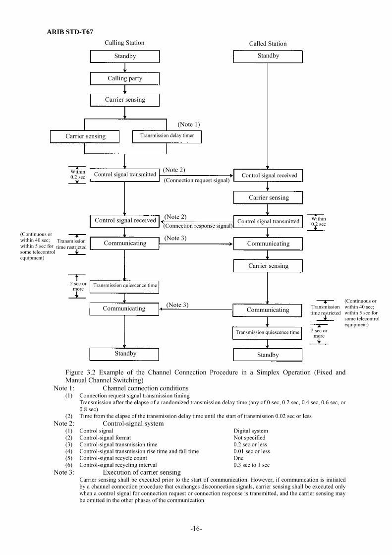
(5) Examples of channel connection procedures Figures 3.2, 3.3 and 3.4 show examples of channel connection procedures when the frequency-switching method is of the fixed or manual type, and Figure 3.5 shows an example of a channel connection procedure when the automatic frequency-switching method is adopted.
ARIB STD-T67
-16-
Figure 3.2 Example of the Channel Connection Procedure in a Simplex Operation (Fixed and Manual Channel Switching)
Note 1: Channel connection conditions (1) Connection request signal transmission timing Transmission after the elapse of a randomized transmission delay time (any of 0 sec, 0.2 sec, 0.4 sec, 0.6 sec, or
0.8 sec) (2) Time from the elapse of the transmission delay time until the start of transmission 0.02 sec or less
Note 2: Control-signal system (1) Control signal Digital system (2) Control-signal format Not specified (3) Control-signal transmission time 0.2 sec or less (4) Control-signal transmission rise time and fall time 0.01 sec or less (5) Control-signal recycle count One (6) Control-signal recycling interval 0.3 sec to 1 sec
Note 3: Execution of carrier sensing Carrier sensing shall be executed prior to the start of communication. However, if communication is initiated
by a channel connection procedure that exchanges disconnection signals, carrier sensing shall be executed only when a control signal for connection request or connection response is transmitted, and the carrier sensing may be omitted in the other phases of the communication.
Standby Standby
Communicating Communicating
Communicating Communicating
Transmission quiescence time
Transmission quiescence time
Carrier sensing
Carrier sensing
Carrier sensing
Carrier sensing
Standby Standby
Calling Station Called Station
Calling party
Transmission delay timer
(Note 1)
(Note 2)
(Note 2)
(Note 3)
(Note 3)
Control signal transmitted
Control signal received
(Connection request signal)
(Connection response signal)
Within 0.2 sec
Transmission time restricted
2 sec or more
(Continuous or within 40 sec; within 5 sec for some telecontrol equipment)
2 sec or more
Transmission time restricted
Within 0.2 sec
(Continuous or within 40 sec; within 5 sec for some telecontrol equipment)
Control signal received
Control signal transmitted

ARIB STD-T67
-17-
Figure 3.3 Example of the Channel Connection Procedure in a Simplex Operation
(Fixed and Manual Channel Switching)
Note 1: Channel connection conditions (1) Connection request signal transmission timing Transmission after the elapse of a randomized transmission delay time (any of 0 sec, 0.2 sec, 0.4 sec, 0.6 sec, or
0.8 sec) (2) Time from the elapse of the transmission delay time until the start of transmission 0.02 sec or less
Note 2: Control-signal system (1) Control signal Digital system (2) Control-signal format Not specified (3) Control-signal transmission time 0.2 sec or less (4) Control-signal transmission rise time and fall time 0.01 sec or less (5) Control-signal recycle count One (6) Control-signal recycling interval 0.3 sec to 1 sec
Note 3: Execution of carrier sensing Carrier sensing shall be executed prior to the start of communication. However, if communication is initiated
by a channel connection procedure that exchanges disconnection signals, carrier sensing shall be executed only when a control signal for connection request or connection response is transmitted, and the carrier sensing may be omitted in the other phases of the communication.
Standby Standby
Communicating Communicating
Communicating Communicating
Transmission quiescence time Transmission quiescence time
Communicating
Carrier sensing
Carrier sensing
Carrier sensing
Standby Standby
Calling Station Called Station
Calling party
Transmission delay timer (Note 1)
(Note 2)
(Note 2)
(Note 3)
(Note 3)
Control signal transmitted
Control signal received
(Connection request signal)
(Connection response signal)
Within 0.2 sec
Transmission time restricted
2 sec or more
(Continuous or within 40 sec; within 5 sec for some telecontrol equipment)
2 sec or more
Transmission time restricted
Within 0.2 sec
(Continuous or within 40 sec; within 5 sec for some telecontrol equipment)
Control signal received
Control signal transmitted
Communicating (Note 3)
Communication terminated Communication terminated

ARIB STD-T67
-18-
Figure 3.4 Example of the Channel Connection Procedure in Semi-duplex and Duplex Operation (Fixed and Manual Channel Switching)
Note 1: Channel connection conditions (1) Connection request signal transmission timing Transmission after the elapse of a randomized transmission delay time (any of 0 sec, 0.2 sec, 0.4 sec, 0.6 sec, or
0.8 sec) (2) Time from the elapse of the transmission delay time until the start of transmission 0.02 sec or less
Note 2: Control-signal system (1) Control signal Digital system (2) Control-signal format Not specified (3) Control-signal transmission time 0.2 sec or less (4) Control-signal transmission rise time and fall time 0.01 sec or less (5) Control-signal recycle count One (6) Control-signal recycling interval: 0.3 sec to 1 sec
Note 3: Execution of carrier sensing Carrier sensing shall be executed prior to the start of communication. However, if communication is initiated
by a channel connection procedure that exchanges disconnection signals, carrier sensing shall be executed only when a control signal for connection request or connection response is transmitted, and the carrier sensing may be omitted in the other phases of the communication.
Standby Standby
Control signal received Control signal transmitted
Communicating Communicating
Transmission quiescence time Transmission quiescence time
Control signal received
Carrier sensing
Carrier sensing
Carrier sensing
Standby Standby
Calling Station Called Station
Calling party
Transmission delay timer
(Note 1)
(Note 2)
(Note 2)
(Note 2)
(Note 2)
Control signal transmitted
Control signal received
(Connection request signal)
(Connection response signal)
Within 0.2 sec
Transmission time restricted
2 sec or more
(Continuous or within 40 sec; within 5 sec for some telecontrol equipment)
2 sec or more
Transmission time restricted
Within 0.2 sec
(Continuous or within 40 sec; within 5 sec for some telecontrol equipment)
Control signal received
Control signal transmitted
Control signal transmitted
(Note 3)
(Disconnection request signal)
(Disconnection response signal)

ARIB STD-T67
-19-
Figure 3.5 Example of the Channel Connection Procedure in Semi-duplex and Duplex Operation (Automatic Channel Switching through the Frequency Control Channel)
Note 1: Channel connection conditions
(1) Data-channel selection Automatic random-selection method (2) Frequency control By the dedicated channel control method. Alternatively, a method that sends frequency control signals on the
data channel may be adopted. (3) Sending of a connection response signal May also be executed by a method that sends a response signal to the frequency control channel after carrier
sensing is performed on that channel Note 2: Control-signal system
(1) Control signal Digital system (2) Control-signal format Not specified (3) Control-signal transmission time 0.2 sec or less (4) Control-signal recycle count One (5) Control-signal recycling interval 0.3 sec to 1 sec (6) Control-signal transmission rise time and fall time 0.01 sec or less
Note 3: Execution of carrier sensing Carrier sensing shall be executed prior to the start of communication. However, if communication is initiated
by a channel connection procedure that exchanges disconnection signals, carrier sensing shall be executed only when a control signal for connection request or connection response is transmitted, and the carrier sensing may be omitted in the other phases of the communication.
Transmission time restricted
Standby Standby
Control signal transmitted
Control signal transmitted
Transmission quiescence time
Carrier sensing
Carrier sensing
Control signal transmitted
Standby Standby
Calling Station Frequency control channel Data channel
Called Station Data channel Frequency control channel
Calling party
(Connection request and Channel designated)(Notes 1, 2)
(Notes 1, 2)
(Note 2)
Control signal received
Communicating
(Connection response)
Control signal received
Within 0.2 sec
(Continuous or within 40 sec; within 5 sec for some telecontrol equipment)
2 sec or more
Transmission time restricted
Within 0.2 sec
(Continuous or within 40 sec; within 5 sec for some telecontrol equipment)
Control signal transmitted
Control signal received
Transmission quiescence time
(Note 3)
(Disconnection response)
Idle channel selected
Idle channel seized
Control signal received
Communicating
(Note 2)
(Disconnectionrequest)

ARIB STD-T67
-20-
3.5 Antennas
(1) Antenna structure (Equipment: Article 49.14) Antennas shall be designed without a feeder or grounding device.
(2) Antenna gain (Equipment: Article 49.14) (Notification: No. 314 in 2000)
The absolute gain of the transmitting antenna shall be 2.14 dB or less. However, when the equivalent isotropically radiated power is the value or less obtained by adding the antenna power of 0.01 W (for the transmitting antenna which uses emissions of a frequency in a range of higher than 413.7 MHz to 414.14375 MHz, higher than 426.025 MHz to 426.1375 MHz, higher than 454.05 MHz to 454.1937 MHz, 0.001 W) to the absolute gain of 2.14 dB of the transmitting antenna, the decrease shall be capable of being compensated for by the gain of the transmitting antenna.
(3) Division in the use of antennas Individual antennas may be used for transmission and for reception. However, the same antenna shall be used for reception and carrier sensing.
3.6 Others
(1) Cabinet (Equipment; Article 49.14) (Notification: No. 49 in 1989)
Radio equipment shall be housed in a single cabinet (including an antenna multicoupler employed at centralized base stations), shall not be equipped with an antenna terminal, and shall not be able to be opened easily. However, the above does not apply to the following: a. Power-supply equipment b. Control unit c. Indicators for displaying the operating statuses of transmitters and receivers d. Volume and squelch controls e. Frequency-switching units f. Transmission/reception switchers g. Associated units and the equivalent
(2) Mark of technical regulations conformity certification (Technical Conformity: Article 8)
The mark of technical regulations conformity certification shall be attached to an easily recognizable section in regulated forms on radio equipment.
(3) Interface with associated units This standard does not provide for interfaces between radio equipment and associated units.
(4) Safety and reliability a. Possibility of redundancy and error-detection functions into data signals shall be considered. b. In the design and operation of a system, thorough consideration shall be given to possible
crosstalk and interference.

ARIB STD-T67
-21-
Chapter 4. Connection to Telecommunications Circuit Facilities
The radio equipment to be connected to telecommunications circuit facilities shall be those required to be equipped with the carrier sensing device under the provisions of 3.4 (4), and shall satisfy the conditions specified below, in addition to those specified in Chapter 3.
(1) Identification sign (Notification: No. 424 in 1994) The radio equipment shall have an identification sign (sign that is designed to identify the radio equipment and is subjected to collation during the establishment of a communication channel; normally contained in a control signal) and shall be composed of 48 bits.
(2) Conditions for interfacing with telecommunications circuit facilities The conditions for interfacing with telecommunications circuit facilities shall conform to the technical standards set forth in the Ordinance Concerning Terminal Facilities Etc. (including the technical conditions defined by Type-I Telecommunications Carriers).
(3) Establishment of a communication channel (Notification: No. 424 in 1994) A radio-wave frequency shall be judged to be idle when the receiver input voltage is 7 μV in the 400MHz band or 4.47 μV in the 1,200MHz band, and a communication channel shall be established only when the radio-wave frequency to be used is idle.
(4) Cabinet (Terminal: Article 9) (Notification: No. 424 in 1994)
Radio equipment shall be housed in a single cabinet and shall not be able to be opened easily. However, the above does not apply to the following units: a. Power-supply units b. Operation controls, indicators, volume controls, and their equivalents c. Squelch controls, frequency-switching units, transmission/reception switchers, associated units
for data signals, and their equivalents
(5) Mark of technical conditions compliance approval of terminal equipment (Terminal Technical Approval: Article 10)
The mark of technical conditions compliance approval of terminal equipment shall be attached to an easily recognizable section in regulated forms on radio equipment.

ARIB STD-T67
-22-
Chapter 5. Measurement Methods
As for the items stipulated in Ordinance Concerning Technical Regulations Conformity Certification etc. of Specified Radio Equipment Appendix table 1 item 1(3), measurement methods are specified by Ministry of Internal Affairs and Communications Notification (Note 1). For other test items, measurement methods generally used shall be applied.
Note 1: This ordinance refers to Ministry of Internal Affairs and Communications Notification No.88 “The testing
method for the characteristics examination” (January 26, 2004) as of the date of the revision of this standard version 1.1 (issued at November 30,2005). Thereafter, the latest version of Notification would be applied if this Notification or contents of this Notification would be revised.
ARIB STD-T67
-23-
Reference Test items in relation to Technical Regulation Conformity Certification for specified radio equipment
The test items in relation to the technical regulation conformity certification for the radio equipment of low-power radio stations are indicated below. (1) Transmitter
Frequency Occupied bandwidth Intensity of spurious emission or unwanted emission (‘Spurious emission intensity’, until November 30, 2005) Antenna power Adjacent-channel leakage power
(2) Receiver Limit on Secondary Radiated Emissions
(3) Other units Transmission time restriction Carrier sensing

ARIB STD-T67
-24-
Reference Precautions on the use of the 1,200MHz Band
Specified low-power radio equipment operating in the 1,200MHz band is likely to cause interference, as the BS/CS broadcast intermediate frequencies and GPS (L2-band) frequencies are close to those of the radio equipment, and may even be identical. a. Study of interference with BS/CS broadcast intermediate frequencies
Most of the interference actually experienced is caused by interfering waves picked up by antenna cables laid between antennas and tuner units and by connectors, with an interference distance of less than 1 meter. In some cases in which a branching filter is used or there are other special circumstances, separation of a distance of some 8 meters must be provided to prevent crosstalk.
b. Study of interference with GPS (L2-band) Interference with GPS receivers is likely to be produced by the direct pickup of interfering waves at their antennas. For interference tests, a separation distance of approximately 10 meters will be required if just one satellite is to be locked onto. Separation between stations of 20 meters or more will be required if four or more satellites are to be captured to enable positional measurement with only the L2 band.

ARIB STD-T67
(1)
Table of Standard Revisions STD Serial Number: ARIB STD-T67 Name of Standard: Telemeter, Telecontrol and Data Transmission Radio Equipment for
Specified Low-Power Radio Station Date established: July 25, 2000 <Note> Related ministerial ordinances, notifications, etc.: Ministry of Posts and Telecommunications Notification No. 272, 273 and 274 in 2000. Revision Number
Date of Revision Contents of Revision Remarks
1.1 November 30, 2005
Determined at the 60th Standard Assembly Meeting
− In ‘1.3 Conforming documents’, “the Ordinance Concerning Technical Regulations Conformity Certification of Specified Radio Equipment” was revised to “the Ordinance Concerning Technical Regulations Conformity Certification etc. of Specified Radio Equipment” referred to as “Technical Conformity”, “Rules Concerning the Technical Conditions Compliance Approval and the Design Authentication for Terminal Equipment” was revised to “Rules Concerning the Technical Conditions Compliance Approval etc. for Terminal Equipment” referred to as “Terminal Technical Approval”, and “a Notification of the Ministry of Posts and Telecommunications” was revised to “a Notification of the Ministry of Posts and Telecommunications if issued in 2000 or earlier, and a Notification of the Ministry of Internal Affairs and Communications if issued in 2001 or later” referred to as “Notification”.
− In line with the revision of titles of related rules
− In 3.2 (11), “Permissible value of intensity of spurious emission” was revised to “Permissible value of intensity of spurious emission or unwanted emission”, “a Definitions” and “b Permissible values applied after January 1, 2006” were added, and the description of permissible values used to be applied was left as “Permissible values based on the Ordinance Regulating Radio Equipment before December 31,
− In line with the partial revision of Ordinance Regulating Radio Equipment (Ordinance No. 119 of MIC in 2005)
ARIB STD-T67
(2)
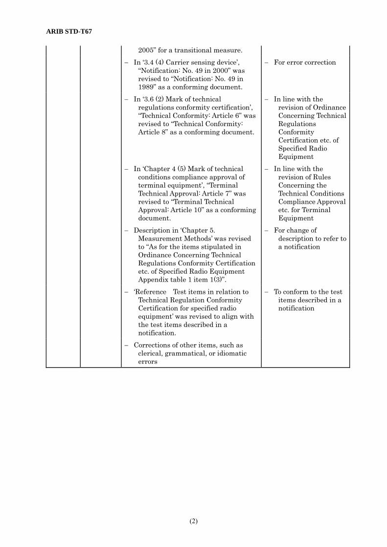
2005” for a transitional measure. − In ‘3.4 (4) Carrier sensing device’,
“Notification: No. 49 in 2000” was revised to “Notification: No. 49 in 1989” as a conforming document.
− For error correction
− In ‘3.6 (2) Mark of technical regulations conformity certification’, “Technical Conformity: Article 6” was revised to “Technical Conformity: Article 8” as a conforming document.
− In line with the revision of Ordinance Concerning Technical Regulations Conformity Certification etc. of Specified Radio Equipment
− In ‘Chapter 4 (5) Mark of technical conditions compliance approval of terminal equipment’, “Terminal Technical Approval: Article 7” was revised to “Terminal Technical Approval: Article 10” as a conforming document.
− In line with the revision of Rules Concerning the Technical Conditions Compliance Approval etc. for Terminal Equipment
− Description in ‘Chapter 5. Measurement Methods’ was revised to “As for the items stipulated in Ordinance Concerning Technical Regulations Conformity Certification etc. of Specified Radio Equipment Appendix table 1 item 1(3)”.
− For change of description to refer to a notification
− ‘Reference Test items in relation to Technical Regulation Conformity Certification for specified radio equipment’ was revised to align with the test items described in a notification.
− To conform to the test items described in a notification
− Corrections of other items, such as clerical, grammatical, or idiomatic errors

To: Secretariat of Low Power Radio-Station working group, Standard Assembly Meeting of the Association of Radio Industries and Businesses
FAX: +81-3-3592-1103 Nittochi Bldg. 11th Floor, 1-4-1 Kasumigaseki, Chiyoda-ku, Tokyo 100-0013, Japan
Communication Note of ARIB Standard-related Proposals, etc.
ARIB Standard Name (No.)
Telemeter, Telecontrol and Data Transmission Radio Equipment for Specified Low-Power Radio Station
(ARIB STD-T67) Sections to be completed by sender
Name: Date / / /
TEL: FAX: E-mail:
Company name Department name
Page / Section (Please describe your proposal or present your questions or comments in concrete terms.)
Sections to be completed by secretariat
Date of receipt / / / (Response)
Ref. No. -
Classification:
Remarks
Please send your ARIB Standard-related question in this format. If you complete this form in English, please provide Japanese translation alongside the English.


TELEMETER, TELECONTROL
AND DATA TRANSMISSION RADIO EQUIPMENT FOR SPECIFIED
LOW-POWER RADIO STATION
ARIB STANDARD
ARIB STD-T67 VERSION 1.1
Version 1.0 Version 1.1
July November
2000 2005
Published by Association of Radio Industries and Businesses
Nittochi Bldg. 11F 1-4-1 Kasumigaseki, Chiyoda-ku, Tokyo 100-0013, Japan
TEL 81-3-5510-8590 FAX 81-3-3592-1103
Printed in Japan All rights reserved