telegraph distortion measuring set type tdms5bvsi)eed and distortion. in respect of the tdms-5abv,...
TRANSCRIPT

TECHNICAL M ANUAL
TELEGRAPH DISTORTION MEASURING SET,
TYPE TDMS5BV
(Basic Models)
NOMINAL SPEED RANGES: SO - 70 - 90 - 170. 190 BAUDS .
A. T. & E.
(Mod. 2)
December 1961
(BRIDGNORTH) Bridgnorth - Shropshire - England
A MEMBER OF
LIMITED
THE AUTOMATIC TELEPHONE & ELECTRIC GROUP
London Office: STROWGER HOUSE, 8 ARUNDEL STREET, LONDON W.C.2.

......
r
J
t .� .. ....,fa ,.
r•
·®,·· ---�.
...._ --�
-·. --.L -- - -
--
I � I �
I T
I �---·� . ,
I I
r
-
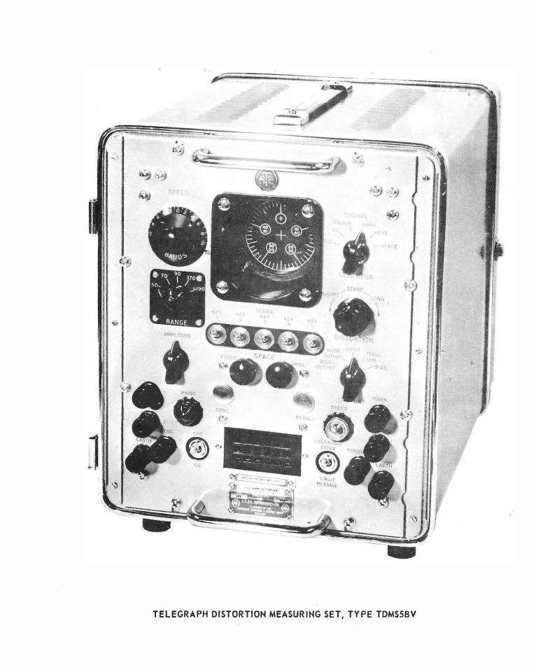
TELEGRAPH DISTORTION MEASURING SET, TYPE TDMSSBV

(SBVISABV)
CHAPTER 1
CHAPTER 2
CHAPTER 3
CHAPTER 4
CHAPTER 5
CHAPTER 6
LIST OF CHAPTERS
LIST OF DRAWINGS
TDMSSBV /SABV Block Schematic
Circuit Diagram
Instrument Layout
Waveforms - 1 .Unit Stop Element (7 Unit Code}
Waveforms - 1Yi Unit Stop Element (7Y�Unit Code}
Waveforms - 2 Unit Stop Element (8 Unit Code)
100 Character Test Messoge
Left-Hand Side ·panel
Right-Hand Side. 'Panel
GENERAL DESCRIPTION
CIRCUIT PRINCIPLES
INSTALLATION
OPERATION
MAINTENANCE
·.COMPONENTS LIST
Fig. 1
Fig. 2
Fig. 3
Fig. 4
Fig. 5
Fig. 6
Fig. 7
Fig. 8
Fig. 9

TELEGRAPH DISTORTION MEASUR ING SET TYPE TDMSSBV & TDMSSABV
C HA PTER l
G E N E R A L D E S C R I. P T I 0 N
CO NTENTS
1. EQUIPMENT ILLUSTRATION
2. PURPOSE AND FACILITIES
3. TYPES OF TEST SIGNAL
4. TELEGRAPH SIGNALLING SPEED
5. VENTILATION ... .. .
6. REFERENCE DATA
7. SHIPPING DETAILS
Page No.
1-7
1-7
1-7
1-7
1-8
1-8
1-9


CH APTER ·1
GENERAL
1. EQUIPMENT ILLUSTRATION
The Telegraph Distortion Measuring Set, Type TDMS5BV or TDMS5ABV is essentially a
portable telegraph test signal generator incorporating a 2%-inch diameter cathode ray tube for monitoring purpase.s.
The instrument is canto ined in on aluminium alloy case. hoving front and rear doors which open to expose the vari.ous controls, output relay and coder.
The instrument operotes from power supplies of 100 to 125, o.r 200 to 250 volts, 5 0 fo 60 cycles a.c. and has a power consumption of 40 watts. In addition, telegraph battery supplies
are required, these may be provided from the normal station batteries or local power units.
In some cases dry batteries can be used to provide these supplies.
The TDMS5 can be combined with its TDMS6 counterpart to form a comprehensive
telegraph distortion measuring equipment. Both instruments con be provided mounted in a housing designed for combined installation on an International 19-inch rock.
2. PURPOSE AND FACILITIES
The purpose of the instrument is to provide a comprehensive selection of accurately derived d.c. telegraph signals for use in setting up, ·routine maintenance and fault location of a v.f.
· telegraph system or network and ossocioted d.c. telegraph equipment. Facilities are also provided for the rapid checking and adjustment of telegraph type relays.
The TDMSSBV provides limited facilities for shunt monitoring and checking of incoming double-current (polar) tele ·graph ··signals for si)eed and distortion. In respect of the TDMS-5ABV, these facilities are extended in that
single-current (neutra I) telegraph s igna Is may be monitored.
Both instruments provide the fol lowing facilities:
(a) Production of perfect teleprinter test s!gnals o.f varia'ble k nown speed.
(b) Introduction of predetermined percentages of s·tart element distortion into these si.gnals.
DESCRIPTION
(c) Testing start-stop receiving mechanism �, including regenerative repeaters, for margin.
(d) Testing telegraph neutrality, transit bounce.
type re fays for time and contact
In conjunction with the TDMS6BV, or 6ABV, the instrument provides very c omprehensive testing facilities for the optimum operation of equipment and systems.
3. TYPES OF TEST SIGNAL
The following test signals can be generated by the instrument:
(a) Continuous 2:2 reversals.
(b) Continuous 1:1 reversals.
(c) Continuous Mark.
(d) Continuous Space.
(e} Repetition of a selected character, determined by the setting of five keys on the front panel.
(f) A test message of 100 characters. A switch on the front panel enables the operator to send a single or continuously repeated message.
· These signals may be sent as perfect (less than 13 distortion), or given any predetermined start element di.stortion up to ±503. The amount ,of distortion is continuously variable between these I im its and is monitored on the cathode ray tube.
4. TELEGRAPH SIGNALLING SPEED
The test s ig no Is may be either 7, 7Y2 or 8 unit code and can be transmitted on any one
of five nominal speeds in the range 40 to 200 bauds.
The basic speed range is centred on 50 bauds with a coverage of ± 10 bauds. Any other
four ranges may be chosen in additi9n to the basic range providing that:
(a) The maximum speed d9es not exceed 200bauds.

1-8
(b) Each range covers ±10 bauds about the centre speed.
(c) Ranges centre on 10 baud intervals.
4.1. Speed Ranges
Any centre speed range between 50 and 190 bauds, in five ranges with the conditions stressed above, may be accommodated on the instrument. The 50 baud speed range is mandatory.
4.2. Calibration Accuracy
A calibration accuracy of ± 13 or better; typica I figures are:
Basic centre speed (50 bauds) - ±0.10 bauds
Extreme ends of range (±10 bauds) ±0.40 bauds
Variation of speed with ±103 variation in mains voltage
4.3. Oscillator Stability
Not greater - than 0.23.
After a -.:varm up period the oscillator stability is 1 part in 103 for long periods and 5 ports in 104 for short periods at an ca1Lient temperature of 2D°C. The max imum ambient temperature for continuous working of the equipment is 40"C, with degraded performance for short periods at 45"C.
4.4. Output Distortion
With the speed correctly set and CJ correctly adjusted output relay, the output distortion does not exceed 13 at 50 bauds and 2.53 at 200 bauds.
·"· 4.5. Hebn Speed Indicator
A neon speed indicator is fitted to the front panel and this, in conjunction with the appropriate stroboscope tuning fork, enables the speed of the oscillator to be checked and adjusted.
5. VENTILATION
When the equipment is used in rooms where the ambient temperature is high, or where the · ventilation is poor, it may be an advantage to. remove the rear door of the portable case, or back panel of the rack mounting case to increase the ventilation of the units.
When the equipment is not being used, the rear doors, or back panel should be replaced and the equipment s tored in a d ry location.
6. REFE��NCE DATA
6.1. Nomenclature
Telegraph Distortion Measuring Set Type TDMS5BV or TDMS5ABV (Portable).
Telegraph Distortion Measuring Set Type TDMS5BV or TDMS5ABV (Rack Mounted) .
6.2. Valve Complement (SBV or SABV)
Quantity 1 - 6X4 - Rectifier
Quantity 1 - 6AQ5 - Pentode
Quantity 2 - 12AX7 - Double Triode
Quantity 13 - 12AU7 - Double Triode
Quantity 1 - DG-7-32 - Cathode Ray Tube
Quantity 2 - CC8L - Neon
Quantity 2 - CC3L - Neon
Quantity 1 - XC15 - Neon
Quantity l - XC12 - Neon
6.3. Power Requirements
100 to 125, or 200 to 250 volts, 50 to 60 cycles a.c. 40 watts.
The eqtiipment also requires normal telegraph battery supplies.
6.4. Additional (Optional) Items
(a) Stroboscope Tuning Fork of 91 cycles for 45.5 baud working.
(b) Stroboscope Tuning Fork of 100 cycles for 50 baud workil'l'Q·
(c) Stroboscope Tuning Fork of 150 cycles for 75 baud working. ·-.,
(d) Relay Test Adaptor, Type RTAT -enables a wide variety of telegraph type relays with differing bases to be tested.

(e ) Telegraph Displa y Unit, Type TDU2 -used with the TDMS6, or combined equipments, to perm it monitoring of voltage waveforms ..
(f) Additional Coding Discs, with varied 100 character test messa ges, c an be pr.ovided for use in the Test Message Coder, Type TDA-10, H. required.
7. SHIPPING DETAILS
Overall Dimensions · Length Width Height
Portable 5BV or 5ABV 18�-in. 11�-in. 13Y2-in. (46.4cm). (28.Scm){34.3�m)
(5BV/5ABV)
1-9
Rack Mounted Version. 19-in. · · 19-in. 14-in. (48.26cm) (48 .26cm) (35.Scm.)
Net Weight -
· TDMS5BV or TDMS5ABV - 38 lb (17.24 kg)
TDMS6BV or TDMS6ABV - 36 lb (16.3 3 kg)
Rack Mounted Version (Combin ed Equipment) - 68 lb (30 .85 kg)
Number of Packages per complete Instrument - 1 .

TELEGRAP H DISTORTI ON MEA SURIN G SE f, TYPE TDMS5BV & TDMS5ABV
1.
?.
3.
4.
5.
6.
7.
8.
9.
10.
11.
12.
13.
14.
15.
16.
17.
18.
19.
CHA PTER 2
CI RCU IT P R I N CIPLES
CO NTENTS
GENERAL ... ... .. . .. . .. . ...
OSCILLATOR (Vl3-Vl4-Vl5-Vl6)
QUADRATURE AMPLIFIER (Vl7-Vl8)
SQUARER (V28-V29)
SCALE-OF-TWO (V30-V31)
DISTRIBUTOR (Vl9 to V26)
GATING CIRCUITS, CODER & KEYS
MARK & SPACE SETTING VALVES (V7-V8)
OUTPUT TOGGLE (V5-V6) & OUTPUT RELAY
OUTPUT FILTER NETWORK
DISTORTER
DISPLAY VALVE (V4)
RELAY TEST CIRCUITS
INPUT TOGGLE (Vl-V2-V3)
INPUT CIRCUIT & ATTENUATOR
SPEED STROBE CIRCUIT (V27-N3)
TEST MESSAGE CODER
POWER PACK . .. . .. ...
SINGLE-CURRENT SHUNT AND SERIES MONITORING
Page No.
2-3
2-3
2-5
2-6
2-6
2-7
2-10
2-13
2-14
2-15
2-15
2-17
2-17
2-19
2-19
2-22
2-22
2-23
2-23


CHAPTER 2
CIRCUIT P�UNCIPLES
1. GENERAL
The heart of the instrument is a highstability variable oscillator which provides the circular trace for the cathode ray tube at twice the frequency of the speed in bauds, of the telegraph signal. It also provides drive, via a squaring stage, to a scale-of-two divider.
The scale-of-two provides pulses at a
repetition rate equal to that of the elements of the signal it is required to generate. These pulses drive a distributor, which is basically an eight-point cyclic counter modified by feedback to give a count of seven. The pulses from the scale-of-two are also passed to a marksetting valve, which, in the absence of action from the distributor, maintains the output toggle at mark.
The output from the seventh anode of the distributor is used to determine the length of the stop element:
For 2 unit stop element (8 unit code) - the seventh anode 01:1tput is not used.
For lJ/.i unit stop element (7)/., unit code) - the seventh anode output is fed back to the scaleof-two.
For l unit stop element (7 unit code) - the seventh anode output is fed back to the distributor.
Note that in the Mark position of the Signal Selector switch, the distributor is open-circuit in position 4 of the wafer S4H. This stops the distributor in such a position that switching either to 'KEYS' or 'CODER' from 'MARK', the start element is always produced first.
Each of the eight anodes of the distributor gives a pulse in turn. When undist.orted signa�s are desired, the pulse from the first anode 1s applied to the space-setting valve which overrides the mark-setting valve and trips the output tcc-gle to the space condition to produce the st�rt element of the character to be transmitted.
The next five anodes give similar pulses coriesponding to the five character elements of thfl signal. These pulses pass through gate
circuits, the gates opened or closed by the setting of the Keys, or by the coder, so tbcit only those pulses corresponding to elements which it is desired to transmit as space signals are passed. In the absence of pulses from the distributor to the space-setting valve, the marksetting valve sets the output toggle to mark. Those pulses which are passed by the gate trip the space-setting valve setting the output toggle to space, thus any character may be set up by the coder, or keys, and transmitted.
To produce long or short element distortion, it is necessary to vary the timing of the pulse which operates the space-setting valve to produce the start element. The method used is to take, instead of the negative pulse from the first anode of the distributor, the positive pulse from the fourth anode. This pulse is then passed to the distorter, where it is subjected to a variable delay, changed to negative polarity and passed to the space-setting valve as the start element pulse for the next character. By varying the delay, this start element pulse may be made up to 503 of an element early or late.
The output toggle drives an output relay which provides signals to the telegraph line, via an output filter network.
The signals to be displayed on the cathode ray tube presentation are selected by the Display switch. With the Display switch set to 'INPUT', signals from the input circuit are dis played. In the 'NORM. OUTPUT' position, internally generated signals taken from the output toggle are displayed. The 'BIAS' and 'TRANS. :r1ME' positions display s ignals taken from the contac!s of a relay under test in the relay test socket, via the relay test circuits. Energising currents for the relay coils, in these tests, are derived from the output toggle. In the 'DIST. OUTPUT' position of the Display switch, the internally generated signals are displayed showing the percentage dist ortion introduced by the Distortion control.
2. OSCILLATOR (V13-V14-V15-V16)
The high-stability oscillator circuit used in the TDMSSBV and TDMSSABV comprises valves V13-V14-V15-V16 and functions as a

2-4
HT+
R l43 R142
v�s
cso
HT-
GRID LEAK R 141
Rl45 Rl44
Basic Oscillator Circuit
resistance-capacity osc ii lator employing a zero phase-shift network.
To fully understand the operation of the oscillator, f irst basic principles should be considered.
Sketch (a) shows a resistance-capacity network which gives an output in phase with the input at one frequency only.
If the output is amplified and fed back to the input, the circuit will oscillate. The oscillation will be at the frequency at which both output and input are in phase.
(a)
Since the instrument requires a push-pull output to drive the cathode ra y tube deflector plates and at th e same time give second harmonic cancellation, two such networks can be combined to give that shown in {b).

y�--------- •N ------------µ
OU'T" (b)
This may be simplified by re-arrangement and combination of components as shown in (c).
Used in this form, the gain of the amplifying valves would be much greater than the network attenuation.
Since only gentle oscillation is required
in this application, additional attenuation is
introduced to the network by the use of cap
acitive potential dividers of which the input
feed capacitors form part. This gives the net
work shown in (d).
,-- -- - - - ----- -- IN -- --------------.
y ..._._-�---9-1 �
T T
(d)
This again can'be re-arranged and simplified to that shown in (e) which forms the basis of the circuit used in the instrument.
(SBV!SABV)
2-5
r------------ - - IN -- - -------------.
y H
0"1'
(e)
Provision is made for locking the oscillator to an external sinewave signal by a synchronizing circuit consisting of RV5-R140-C40. Variable resistors RV14 and RV15, connected between V13 and V14 cathodes, control the gain of the circuit and hence the amplitude of oscillation. These are shown on the main circuit diagram of Figure 2.
It is usefu I to note at this point that the two Amplitude controls, RV14 and RV15, control both the horizontal scan voltage applied to the cathode ray tube 'Y' plates and the osci I latory voltage fed to the quadrature amplifier and squarer circuits and therefore control the diameter of the circular display.
It should be noted that the cathode ray
tube is mounted so that the 'Y' plates provide the horizontal scan and the 'X' plates the vertical scan, as opposed to normal oscilloscope practice.
3. QUADRATURE AMPLIFIER (V17-V18)
The quadrature amplifier comprises V17-V18 operating in push-pull. Voltages from the oscillator network are fed to the two grids and are in quadrature-phase to the voltage appearing across C51. The para-phase voltages appearing at V17 and V18 anode provide the vertical 'X' scan, which is therefore in quadrature-phase with the horizontal 'Y' scan and a circular trace results. The Shape preset RV17 controls the gain of the quadrature amplifier and therefore only affects the vertical scan. This enables adjustment for a perfectly circular trace.

2-6
4. SQUARER (V28-V29)
The squarer stage can be regarded as a twostage over-driven cascade amplifier providing para-phase outputs at V28 ond V29 anode. The squarer is driven by a s inewave from the cathode of cathode-follower valve Vl6 which is applied to V28 grid. Output from the squarer ultimately drives all circuits in the instrument concerned with the internal generation of test signals.
5. SCALE-OF-TWO (V30-V31)
The output from one anode of the squarer Y29 is fed to a diode MR16 which allows only negative going pulses to pass. Negative going pulses of short duration are applied to the grid of both V30 and V31 by the action of C58-R21 l and C59-R210.
Valves V30 and V31 form c bi-stable multi-
HT+
vibrator such that when V30 is conducting, Y31 is cut off b y cathode bias developed across R212 and the low grid potential from V30 anode.
When the negative going pulses are applied to both grids, V30 wil I be driven beyond cut-off and its anode potential will rise. By regenerative action V31 will be forced into a fully conducting condition and V30 cut off. The low anode potential of V31 holds V30 grid beyond cut-off value and the circuit remains stable in this condition until the next negative going pulse is applied to both grids causing the reverse action to take place.
The voltage waveform appearing at V30 anode is therefore rectangular and at half the frequency of the oscillator. Output is taken from V30 anode load potential divider. MR15 ensures that only positive d rive pulses are applied to the distributor.
IN 1-{T +
Sea le-of· Two

6. DISTRIBUTOR (V19-V20-V21-V22-V23-V24 V25-V26)
The distributor is basically an eight-phase cyclic counter which can be modified by f�edback to give a count of seven. In operation, four adjacent valves on the circuit diagram are conducting and the four opposite valves are
. cut
off. On receipt of positive pulses at the combined grid circuit, the four conducting �tates �e�ome shifted together, one step at a time, grvmg a series of negative edges in rotation.
HT+
2-7
The operation of a cyclic counter of this type may be more readily understood by fir�t considering an elementary circuit of similar type.
For the purpose of explanation, let it be assumed that the anode potential of any valve in the simplified four-phase circuit is 300 volts when cut off and 100 volts when conducting
HT+.
Simplified Four-Phase Cyclic Counter
(SBV/SABV)
2-8
Let it also be assumed that Yl-V2 are conducting and V3-V4 cut off. The potentials al
points W, X, Y and Z will then be W=lOO; X=250; Y=300 and Z=l50 volts. These are the valve grid potentials as indicated by the connections from these points to the four valve grids. (In a practical circuit only a fraction of these potentials would be obtained). Assuming now that the potentia I required at any of these points to maintain a valve conducting is 200 volts, V1-V2 will be conducting and Y3-V4 cut off.
Now, if a SO-volt pulse is sumultaneously applied at all four points, Z will rise to 200 volts and V3 wil I conduct (V3 is in a 'preferentia I' condition compared with V4 since the potential at Z is greater by SO volts than that at W). V3 anode wil I fall to 100 volts, causing Y to fall to 2SO volts and X to 100 volts. Vl will cut off and the anode potential will rise to 150 volts and Z 300 volts.
V2-V3 are now conducting and Y4-Yl cut off. V4 now occupies the 'preferential' position point W being at 150 volts compared with l 00 volts at X. The next pulse therefore cuts on V 4 and cuts off V2.
The.circuit used in the instrument operates in this manner, but consists of eight valves instead of four. In this case let it be assumed that V20-V21-Y22-V23 are cut off and V24-V25-V26-Vl9 conducting. This is the state at the end of a stop element, and can be seen in Figures 4, 5 and 6, under reference scale '0', Vl9 anode to V26 anode waveforms.
Following the same principle and assuming the same voltages, then the potentials at points Q R S T W X, Y and Z are Q=250; R=300; S�OO; T=300; W=l50; X=lOO; Y =100; and Z=lOO volts.
A 50-volt positive pulse to the distributor combined grid circuit raises point W to 200 volts and Y20 cuts on, sin ce V20 holds the 'preferential' position. At this instant V20 anode falls to 100 volts lowering point Q to 100 volts and R to 250 volts. The potentials are then R=250; 5=300; T =300; W=300; X=l50; Y =100; Z=lOO and 0=100 volts, with V25-V26-Yl9-V20 conducting and Y21-Y22-Y23-Y24 cut off; V21 now holding the 'preferential' position. The distributor has stepped round one position in an anti-clockwise direction on the circuit diagram and now corresponds to the end of a start element. This is shown in Figures 4, 5 and 6, reference scale '2' Vl9 to Y26 anodewaveforms.
The process is continuously repeated, the distributor continuously stepping round one stage at a time for each positive pulse applied to the combined grid circuit.
The anode waveform of the eight distributor valves is obviously rectangular. The negativegoing leading edges are, with the exception of V26, differentiated to form short pulses. These short pulses trigger all succeeding stages of the instrument.
The length of stop element is determined by the time taken by the distributor to change from the sixth to the eighth position. Where a stop element length of 1 unit only is required the differentia.ted negative pulse from V25 anode immediately cuts off V22 via link LK1. V26 cuts on so that the distributor steps from position 6 to position 8 on one pulse from the scale-of-two in the time of l unit. In effect, the distributor completes. one revolution for 14 cycles of the oscillator.
To obtain a 1Y2 unit stop element, link LKl

is set so that the negative pulse from V25 anode is fed back to the scale-of-two valve V31 cutting on V30. The next pulse from the squarer, which arrives half a unit later in time, cuts off V30 feeding another positive pulse to the distributor. The distributor, under this condition, steps from position 6 to position 8 in the time of
2-9
1}'2 units, therefore completing one revolution for every 15 cycles of the oscillator.
For a 2 unit stop element, no feedback is applied and the distributor makes its normal c ount of 8, changing from position 6 to position 8 in the time of2 units completing one revolution for every 16 cycles of the oscillator.
HT+
HT.,.
Eight-Phase Cyclic Counter Circuit
(SBVISABV)
2-10
7. GATING CIRCUITS, CODER & KEYS
7.1. Gating Circuits
The five negative-soing edges from V20-V21-Y22-Y23-Y24 anodes pass to gate circuits. The edges are differentiated and the positivegoing pulses suppressed by rectifiers MR21-MR23-MR25-MR27-MR29. At this point, the negative pulses may be individually shortcircuited by the action of Signal Selector S4, Coder or Keys. The unsuppressed pulses pass through rectifiers MR22-MR24-MR26-MR28-MR30 to space-setting valve V8. These rectifiers isolate the gates preventing an earth introduced to one gate being applied to the remaining four.
To obtain 2:2 or 1:1 reversals, the Signal Selector over-rides link LKl so that the distributor provides a count of eight.
7.2. Coding Circuits
With the Signal Selector in the 'CODER' position, earth connections to the gates are controlled by the coder wiper contacts. The wipers make contact or not, depending upon the particular character code, with a series of metal segments printed on an insulated plate. Contact between wiper and meta I segment provides a mark signal. Space is the condition where the wiper is on an insulated segment.
After transmission of a character, the disc is moved round one step bringing into position a new combination of meta I and insulated segments. In this way a test message of up to 100 characters may be transmitted.
To give the disc rotational movement during the fifth character element, a coincidence gate consisting of MR17-MR18 gate out a negative pulse of one unit duration from the condition of V21 and V24 anodes at this period when V21 and V24 are simultaneously conducting. This is inverted by Vl 0 and actuates the coder drive valve V9, which is normally held cut off by negative bias applied to the grid. V9 therefore steps the coder one position during the fifth element of each character. This can be seen by the coder waveforms shown on page 12,
7 .3. Single Message Operation
Reference should be made to the s implif ied ·
c;oderdrive c;irc;uitshown on page2-11. Assuming
the coder to be held in the rest posit ion at the end of the message corresponding to the lOOth position of the disc, coder change-over switch contacts 8 and 18, printed on the coding disc, are closed. The initial conditions for single message operation are as described in the following paragraphs.
With the Signal Selector set to 'CODER' and Continuous/Single message switch S2 set to 'SINGLE MESSAGE' (contacts closed), V9 cathode load resistor is short-circuited ta earth via S4J. V22 anode is held at low pot ential via neon N6, S4F, S2 and contacts 8 and 18, to earth. This holds the distributor so that V22-Y23-V24-V25 are conducting and V26-Vl9-V20-V21 are cut off, this is the distributor steady mark state.
To transmit a single message, S2 is set to 'CONTINUOUS'. This breaks the neon hold circuit and the distributor starts. The first coincident negative rectangular excursion of V21 and V24 anode steps the coder one position.
When this happens the coder switch changes over closing contacts 18 and 11. The coder continues to operate unti I the end of the message S2 should now be returned to 'SINGLE MESSAGE' before the end of the test message is reached. At the lOOth position of the coding disc, contact 18 changes over to 8. This applies the neon hold circuit and the distributor is held with the coder in the rest position until S2 is again set to 'CONTINUOUS'. Obviously, if S2 is left at 'CONTINUOUS', the test message will be continuously repeated.
Another interesting feature of this circuit is that should the coder be operating and the Signal Selector turned to another position, such as 'KEYS', the selected output will be transmitted but the coder will continue to step on
until it reaches the rest position at the end of the message, and Y9 cathode load resistor is re-inserted by the change-over contacts.
The operation of the circuit is now as follows, assuming the coder to be in the middle of a test message and S2 set to 'CONTINUOUS'.
Contacts 18 and 11 are closed. If the Signal Selector is moved to either 'REVERSALS' or 'KEYS', V9 cathode load short-circuit to earth via S4J is removed, but V9 cathode remains at earth potential via contacts 11 and 18. When

MRll
MRl2
CODER DRIVE HT.
CHANGE-OVER sw:TCH WIPERS ON CODING DISC. 8-18 ARE MADE IN THE IOOTH POSTION ONLY.
R42
54F
S4J
HT-
0 0
0
0 0
0 0 0
Simplified Coder Drive Circuit
(SBV/SABV)
2-11
HT.
NS
MRl8 ...,__._,....... __ V24
MRl7 .__ .... �--v21
--
N6
MRl9
R46
V22 ANODE
V26 GRID

2-12
0 . I 2 3 4 5 6 7 8
r�-, T--�--�--�--l---�-1--�---i
I Dl$1RIBUTOR I I I I 60V I I ANODE+ I .L I r--1--r--r-- --t--1-- --�--! I I I I 1 1 I I I �--�--�--t--1--�--T--�--L-� I v 24 I I I 60 v 1 I Dl$TRIBYTOR I I 1 I I l�NODE. t--- - -1--L--1- --�--L __ I I I I I 1 I I I 1---L--r---+--�-- L--�--�-- T1 ___ 1 I VIO
I I I I I I I I t.:-ODEQ �RIVE4
__
j __
_
l- --�-- 20�j _
_ j
I VALVE I GRID. I I I I I I OUTPUT FROM I GATE I I I
I I I I I ! \ I I
1--t--1--1----,---,---__ J ___
I I I I I I I I : I
v 10 I : I I I ISOV I I
�ODE� toRIVEI- --i----1---tl -- ---1-- -II I VALVE ANODE I I
j--t-�--i--�---l--�--�--+--1 I V9 I I I I I 300V I rcooERlvA�[r-- f-- 1---1-- - �---1--I
I ANODE I I I I I I I I I I I I I I I I I �--+---+---t--1--+--- -+---f---1 I I I I I 1 I I I I I I I I I I I I I L __ L __ l __ J __ j_ __ _! __ _J ___ L ___ , _ _ J
Coder Waveforms
(SBVISABV)

the coder reaches the lOOth disc position, the coder switch changes over to 18 and 8 reinserting V9 cathode load resistor cutting the valve off and preventing further stepping of the coder.
Rectifiers MRl l-MR12 across the coder d rive coil eliminate any possible over-shoot which might be present during operation.
At high speeds, it might be possible for the
V6 G�ID
OUTPUT TOGGLE.
2-13
8. MARK & SPACE SETTING VALVES (V7-V8)
8.1. Mark Setting Valve (V7)
The mark setting valve is normally cut off by cathode bias produced by R25-R26 and its anode potential is normally high. A positive pulse from the scale-of-two cuts V7 on and the negative pulse produced at the anode is passed to the output toggle, the positive return pulse being suppressed by MR?.
C21 DISPLAY . � SWllCH
SIC
INPUT FOOM
'-----GATING Al'V
CODER CIRCUITS
EARTH ....._ __ SCALE-OF-TWO
V19 ANODE
Simplified Mark and SDace Setting Valves
coder to over-ride the switch contacts in the ' SINGLE ME S SAGE' position of S2 so that the coder disc goes round again. To overcome this effect, neon NS is connected to Vl 0 anode. via MR20, S4F, 52 and contacts 8 and 18, so that at the end of the message VlO anode is earthed via the neon. This reduces the amplitude of the pulses at VlO anode below that necessary to drive V9. This inhibits any pulses which might other wise operate the coder drive valve.
(SBV/SABV)
The mark re-setting pulse from the scaleof-two corresponding to the commencement of a normal start element is suppressed at V7 grid by the negative-going transition of V 19 after differentiation across C 18. MR9 suppres�es positive pulses from Vl9 anode.
Suppression of the mark re-setting pulse is necessary so that long start element distortion can be introduced when the Display switch is set to 'DIST. OUTPUT'. This is dealt with
2-14
further in section 11 of this chapter.
8.2. Space Setting Valve (V8)
The space setting valve normally conducts heavily owing to R33-R34 being retu rned to h.t.+ and the absence of cathode bias. A negative pulse from Y19 anode, via C21-MR10, or negative pulses from the gates, produce a large positive pulse at va anode which is differentiated across C16 and passed to the output toggle. MRS suppresses the negative return pulses across C16.
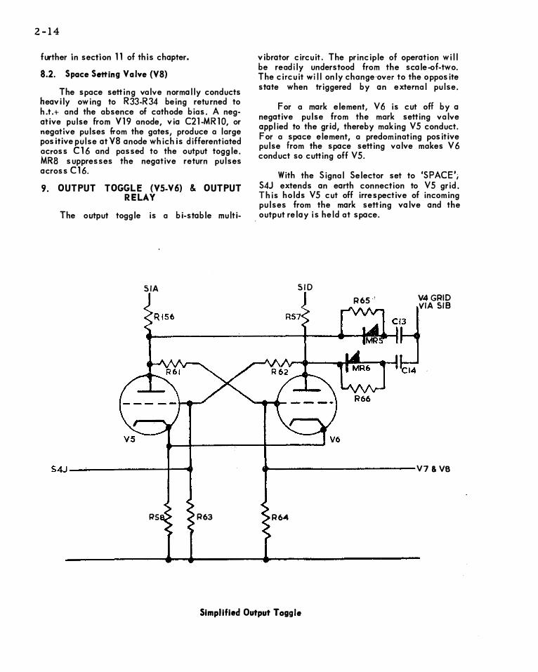
9. OUTPUT TOGGLE (YS.-V6) & OUTPUT RELAY
The output toggle is a bi-stable multi-
SIA
S4J---�-------------------+----1'
RS R63
vibrator circuit. The principle of operation will be readily understood from the scale -of-two. The circuit will only change over to the opposite state when triggered by an external pulse.
For a mark element, V 6 is cut off by a negative pulse from the mark setting valve applied to the grid, thereby making V5 conduct. For a space element, a predominating positive pulse from the space setting valve makes V 6 conduct so cutting off VS.
With the Signal Selector set to 'SPACE'; S4J extends an earth connection to VS grid. This holds VS cut off irrespective of incoming pulses from the mark setting valve and the output relay is held at space.
SID
R65' V4GRID VIA SIB
..., ____________ v1 & va
R6"'4
Simplified Output Toggle

With the Signal Selector set to 'M ARK', negative pulses from Y7 hold Y6 cut off and the output relay is held at mark.
In the Display switch p ositions 'DIST. OUTPUT', 'NORM. OUTPUT' and 'INPUT' ' the output toggle drives the output relay, but in the 'TRANS. TIME' and 'BIA S' positions, the toggle output is fed to the relay test socket on the front panel so that an external relay under test is energised when plu gged into the test socket.
10. OUTPUT FILTER NETWORK
The output filter network consists of spark quench circuits, interference suppressors and barretter lamps.
The spark quench circuit consists of R 22-
2-15
R23-Cll-C12 and reduces the effects of sparking at the relay contacts.
Capacitors C8-C9..C:l0 suppress radio interference and barretter lamps LP1-LP2 limit the I ine current under short-circuit conditions.
11. DISTORTER (V11-Vl2)
Positive transitions ofY22 anode are passed via MR13-C33, to Yll grid. This corresponds in time to one element earlier than the normal start element pulse derived from Y19. MR13 suppresses negative transitions from Y22 anod�.
Yl 1-Y12 form a mono-stable multivibrator circuit which, in the absence of external action will return to, or remain in the condition of Vl2 conducting and Yl 1 cut off. A positive pulse applied to Yl 1 grid cuts on Yl 1 and cuts
.------------..,---------------------�------------...--- HT
RSI
C39
(5BV/5ABY)
MR 13
R78
R82 RVI&-
R36
R84 R79
--------- V 22 ANODE
Simplified Distorter Circuit

2-16
___ o_ -�---L--�---�--2-__ L __ L--�--� I I I
I I I I I I I I I I I I I 1 ! I I 1 I I I I I I I I 1 I 1 I I I I I I I I I
I V22 J��g��UTOR I I 60V j I I I
� V} DISTO� TER n : IL GRID · I\ 2ov: I I I
I I ) I I I I I I
.---
1 I I
VII Dl':>lORlER l ANODE 60V I I
_........_ ___ J ___ _. __ J
I I I l I I I
I I 1 I I
I I I rn-:-� V12 OISTO�TER I I l-���A-N_o_o_E-----------------------,�6-o_v_.
I I
I I I : I I I I
I I I 1.' ,J v
I VB GRID INPUl 10 SPACE ' 1
I I $Ell1ING VALVE I I I 1 1 1 ols10RTER WAVEFORM s
I I I I I I
i i=t--��, -1 -1 �����--1 I I I I
35V
I I
I/ I f 1 I U I
I ( I
if_J I
I I OUlPUlWAVEFORM-LElTERZ- 8UNITCODE - 2UNH STOP I I -+50°/0 SlART ELEMENl DISTOR TION I L __ l_ __ _! _ - _1
____ 1 __ l_ __ _J ___ � __ _!. ___ � __ I
Distorter Waveforms

off Vl2. After a time delay set by RVla-RV1b, the circuit returns to its original state. When V12 cuts on again, a negative pulse is fed via SlC to space-setting valve V8 grid.
SlC is part of the Display switch and disconnects the normal pulse from Vl9 anode in the 'DIST. OUTPUT' position. Thus the pulse corresponding to the beginning of the start element normally fed to the space setting valve has been removed and replaced by one of variable timing.
This is shown on the distorter waveform diagram on page 16.
The fine control RVlb (outer knob) gives a variation of approximately ±43 total on any setting of the coarse control RVla.
12. DISPLAY VALVE (V4)
V4 grid resistor is returned to h.t. positive therefore the valve normally conducts heavily. Signals selected by Display switch wafer SlB
R69
0 0
V2 & VJ ----"'0 SIB
RELAY � TEST
SOCKET-1 CS
2-17
are applied to V4 grid. These ore negative pulses of sufficient amplitude to cut the valve off.
Positive pulses appearing at V4 anode are applied to the cathode ray tube grid causing a bright-up on the trace at that instant.
Since the negative input pulses selected by the Display switch are derived from both anodes of the input and output toggles, all transitions of a rectangular waveform are displayed.
13. RELAY TEST CIRCUITS
The relay under test is plugged into the relay test socket situated on the front panel. The relay coils are driven by the output toggle via Display switch wafers SlA and SlD in the 'TRANS. TIME' and 'BIAS' positions.
13.1 Bias Test Circuit
The relay bias test circuit may be simp-1 ified as shown on the next page.
R71
-----1� 1-------CRT GRID C31
R72
V4
Simplified Display Valve
(SBVISABV)

Z-18
r--
I
� 6
MR3
I
I 18 �Ml
-r-R4
I
7
SIF 0
'1-----HT-
R21
I ·-- 1_ _ __ ___,
HT+
R69
CONTACTS RELAY UNDER TEST
V4 GRID CS
Relay Bias Test Circuit
With the Display switch set to 'BIAS', S 1 F applies a negative potentia I, derived from the ne9ative h.t. rail, to the relay contacts via R18 and R21. MR3 and MR4 are non-conductive durinq bias testing and may be ignored.
I I
t'" tC& -"-
,--I ' I I
--...J
CONTACT$
--
When the relay tongue is in transit, C6 and C7 wi II discharge through R18 and R2.1 respectively, allowing the contacts to fa II to the fu II negative potential. When the relay tongue makes contact with either static contact, the tongue
I
��' IC7
-L-.--
I I I
---' HT+
UNDER TEST
V4 GRID
Relay Transit Time Test Circuit

potential falls to that of the contact, rapidly returning substantially to earth potential as the appropriate capacitor C6 or C7 charges through Rl7. This negative pulse is passed by C5 to display valve V4 grid producing a bright spot on the trace.
The time constants C6-R 18 and C7-R21 are long enough to prevent complete discharge of the capacitors during contact bounce, but the pulse produced by the tongue again making contact after bouncing is much smaller than the original. Contact bounce is therefore not conspicuous on the Bias display.
13.2 Transit Time Test Circuit
The circuit for this test is shown on the previous page.
Display switch wafer Sl F applies a positive potential via MR3 and MR4 to the relay static contacts. C6-R 18 and C7-R21 may be disregarded since they are effectively short-circuited by the rectifiers during transit time testing.
When the relay tongue makes with either static contact, the potential at point B is rai:>ed almost to that of point A, due to the low forward resistance of the rectifiers. The display valve V4 is conducting and any positive potential which appears at the grid is absorbed by grid current flow and has no effect on. the display.
When the tongue leaves a static contact, the potential at point B falls rapidly. This fall is fed via CS to V4 grid cutting the valve off. Since V4 is now cut off, the grid circuit time constant is that of C5-R69, which is long enough to hold V4 cut off until the tongue again touches a static contact. When this occurs, .the potential at point B again cuts on V4. Only when the tongue is in transit is V4 cut off, therefore transit time is displayed as CJ bright arc on the trace.
As the bright arcs due to transit tr me in both directions are superimposed, the display gives a true measurement of transit time only .vhen the relay is correctly adjusted for bias (neutrality).
(5BV/5ABV)
2-19
Since with this display, V4 is fully released and again cut off at each contact bounce, the effect of contact bounce shows up as one or more bright spots at the end of . the transit time arc.
14. INPUT TOGGLE (V1-V2-V3)
The input toggle consists of switching valve Yl and bi-stable multivibrator circuit V2-V3. Vl is arranged to have a very short grrd base to enable small values of input signal to completely cut the valve off or make it fully conduct.
The switching valve is directly coupled to the multivibrator, taking the place of V2 grid leak. A positive input to Yl cuts off V2 allowing V3 to conduct. A negative input causes the reverse condition. Since only a small potential is required to completely cut off Yl, the input to the circuit must be balanced with respect to earth potentia I.
The anode waveforms of V2-V3 are rectangular. With the Display switch set to 'INPUT', negative pulses are passed to display valve V4 grid, while MR1-MR2 suppress the positive pulses. Each transition of the input i s thus displayed as a bright spot on the trace.
15. INPUT CIRCUIT & ATTENUATOR
The SBV and SABV models differ widely in respect of the signal input circuit. The SBV models are designed for shunt monitoring of ·double-current (polar) t elegraph signals only:
The SABV models incorporate a singlecurrent to double-current converter circuit .enabling these models to be used for monitoring of. single,current (neutral) signals as an additiQnal facility. This extra circuitry for :;,nglec:;rrent monitoring is necessary since the signal pres�nted at switching valve Vl grid must br: balanced with respect to earth potential.

2-20
15.1. SBV Input Circuit
INPUTe-------------------�---------------2
IMPEDANCE
HIGH
INPUT r I ....,0.__-0"
LOW
LINK-LK
R2
RI R4
R3
EARTH o------------------------... ------�------------.... --------------
TDMS5BV Input Circuit
Signals applied between the Input 2 and Earth terminals pass direct to Yl grid. With the input impedance link LK2 set to 'HIGH', signals appearing between the Input 1 and Earth terminals pass via a 10: 1 attenuator to Vl grid. With LK2 set to 'LOW', the attenuator is not in circuit.
The settings on input link LK2 with respect to the input impedance can be summarized as follows:
HI GH LOW
INPUT 1 impedance (200kG) LOW sensitivity. impedance (lkU) HIGH sensitivity
INPUT 2 ·
HIGH impedance (200kn} HIGH sensitivity.
Therefore, between the Input 1 and Earth terminals, the impedance may be high or low according to Link LK2, while the input sensitivity is inverse to the impedance.
Between the Input 2 and Earth terminals, the impedance and sensitivity are both high.
The signals applied between the Input 1, or Input 2 and Earth terminals must be balanced
with respect to earth potential in order to operate switching valve Vl, and is intended for operation on double-current (polar) signals only with the instrument strapped across the circuit for shunt monitoring.
15.2. SABV Converter Circuit
In these models, a single-current to double. current converter circuit is incorporated between the input attenuator and switching valve Yl.
The converter is designed to enable series (current) monitoring of single-current (neutra I) signals and presents them as double-current (polar) signals at Vl grid.
The operation of the converter is controlled by the Input switch 58 which, in the centre position by-passes the converter allowing shunt monitoring of normal double-current signals.
Consider the converter circuit with the Input switch 58 set to 'S.C.-M' and the input impedance l ink LK2 set to 'LOW', resistor R3 is then the resistance inserted in the telegraph circuit for series monitoring and the voltage developed across R3 will be proportional to the line current.

2-21
TDMS5ABV Input Circuit
When a single-current negative mark signal is applied between the Input 1 and Earth terminals, MR37 conducts during the first negative signal element and a negative potential appears across C20 equal to the voltage appearing at the input end of RS. R75 and R19 form a potential divider across C20, the centre of which is connected to Vl grid. Consequently, a negative potenti.al approximately equal to half the input voltage appears at Vl grid.
At the next signal transition when the current falls to zero, MR37 becomes nonconducting and R19, R75 and MR40 provide the only discharge path across C20.
The input end of R5 is now at earth potential; C20 has not changed its state of charge and a positive potential approximately equal to half the voltage across C20 appears at Vl grid.
Therefore the s igna I a pp I ied to V 1 grid is a rectangular waveform balanced with respect to earth.
·
(SBV/SABV)
In the 'S.C.+M' position of the Input switch 58 and with a single-current positive mark signal applied to the input, the reverse action takes place and c20 charges to a positive potential via MR38 during the positive signal elements.
In any position of the Input switch 58, the impedance and sensitivity as determined by link LK2, or the Input 1 and Input 2 terminals are the same as given i.ri 15.1.
16. SPEED STROBE CIRCUIT
To ensure reliable operation of speed indicator neon N3 over the entire instrument speed range, the neon is driven from a hard valve circuit.
The output from squarer stage V28 anode is fed via C55 and grid stopper R194 to indicator ·
drive valve V27 grid. The grid is biased·negativeby R190-R191 so that the valve is normally cut off. Consequently there is no voltage drop across R192 and the neon cannot strike.

z-zz
N3
css l--V28
ANODE
Simplified Speed
V27
Due to the differentiating action of V27 grid circuit, a positive pulse from V28 anode cuts t-he valve on. The voltage drop across R192 then ionizes and strikes the neon.
The neon duty cycle is largely controlled by the time constants of V27 grid c ircu1t. The neon is struck and extinguished once for every cycle of the osc ii lator and can be observed through the sight of a stroboscope tuning fork to check the oscillator frequency.
17. TEST MESSAGE CODER
The Test Message Coder, Type TDA 10� supplied with the instrument provides the 100-character test message facility and is the subject of a separate Technical Manual.
Basically, the coder is a printed disc consisting of an insulated plate covered with a suitable metal which is etched to give five concentric tracks corresponding t o the five elements of the Murray code.
The coding and switching contacts take the form of a contact wiper assembly attached to a moulded contact bridge so that the wiper tips bear I ightly on the tracks of the printed
Indicator Circuit
image, making contact with a metallic or insulated segment. The metallic segments of the coding tracks are connected together a-nd earthed through a coding earth return contact wiper.
The coding earth return and three switching contacts are grouped at the opposite encl of the bridge and are aligned to concentric tracks near the centre of the disc.
The five coding contact wipers are alrgned to tracks near the circumference of the coding_ disc, the first coding element being the inner of the five tracks and the fifth element the outer track.
Each coding contact is connected via the Signal Selector S4 to the coding gate controlling the pulses to space-setting valve V8 grid appropriate to the position of the element in the character. The five coding contacts are sampled sequentially and at the fifth element, the disc is stepped on to the next character by the action of the coder drive valve.
The actual test message on the disc supplied with the coder, together with its various carriage return, line feed and spacing tests is set out in Figure 7.

18. POWER PACK
The power pack in the 5BV and 5ABV IS models differs slightly in that the mains earth connection is isolated from the chassis in the 5ABV /S models.
18. l SBV Series
The mains power supply is fed to the instrument via a three-way socket. The mains input circuit is switched by a double-pole On/Off switch S6 and protected by fuses Fl, and F2, which are on the input side of the switch.
The mains transformer has two tapped primary windings which may be connected in series or parallel permitting operation on a.c. supplies of 100 to 125, 200 to 250 volts in 5-volt increments.
A ful lwave valve rectifier V32 provides a +220 volt h.t. supply smoothed by C71-Rl85-C74. This supply is fed to all circuits in the instrument including the first and final anodes of the cathode ray tube. The h.t. line to the oscillator circuit is further smoothed by the act ion of R 1 S6-C75.
Metal rectifiers MR31-MR32 are connected to taps on the h.t. winding and provide a -150-volt supply, smoothed by C72-Rl83-C73 and fed to the oscillator, coder, relay test and speed indicator circuits.
Also connected across the transformer h.t. winding is a fullwave negative voltagedoubler network C76-C77-MR33-MR34-MR35-MR36-C79, the output of which is added to the -150-volt supply; the combined output of approximately -750 volts is smoothed by Rl84-C78 and fed to the cathode and grid of the cathode ray tube.
Three separate heater windings on the transformer provide the supplies to the rectifier valve, instrument valves and cathode ray tube heater. Since the cathode ray tube heater operates at the cathode potential of -750 volts, the winding providing this heater supply is specially insulated.
19. SINGLE-CURRENT SHUNT AND SERIES MONITORING
One disadvantage of the TDMS5BV is that
(SBVISABVJ
2-23
the Input facility will only accept dot•l:ile-current (polar) signals, which restrict its use as a receiver, or as a complete loop tester, i.�. transmitter-receiver.
On the 5ABV and 5ABV/S models a passive single-current to double-current converter is incorporated for measurements on single-current positive, or negative mark systems. The telegraph signal is automatically sampled at its mid points, but it has the limitation that its use is restricted to signals which fall to zero volts or earth potential in the space condition. As the dis play is a cc.ntinuous circular timebase, only signals which have a character length of an integral number of half-elements will be displayed satisfactorily.
19.1. 5ABV Models
This model is designed to shunt monitor single-current . systems, i.e. the TDMS is connected right across the signalling loop to monitor the signal voltage. The input impedance should be set to HIGH (220kll) by means of LK2 {left-hand side panel).
19.2. 5ABV/S Models
This model is designed for series monitoring of single-current systems. In this case the instrument is connected in s�ries with the signalling loop to monitor the signal current.
The mains transformer screen and mains earth connection are isolated from the chassis. This is essential because the Input terminals are not isolated and the chassis must therefore float to the ful I value of the telegraph line potential. Care must be exercised to ensure that the case and chassis are not earthed under these conditions.
In the standard model the value of input series resistance can be set to lkll by means of link LK2 (LOW IMPEDANCE), but values down to 270ll on a 60mA circuit should be satisfactory.
Shunt monitoring can also be used merely by setting LK2 to HIGH IMPEDANCE (220kn).
The models which have the mains earth isolated from the chassis for series monitoring are identified by the suffix "/S" after the type number, i.e. TDMS5ABV /S.

2-24
19.3. Conclusi�'!
It should be noted that the explanations throughovt the Manual refer to series monitoring, but the principle of operation of the singlecurrent to double-current converter is the same for both shunt and series monitoring, the only
difference being the manner in which a voltag.:; is derived to operate the converter.
The single-current to double-current converter is described in this chapter, Page 2-20, Section 15.2, and Chapter 5, Page 5-10, Section 2.10.