telecommunications document type: dgl guideline: design ... · technical bulletin dt 018/97 rev.2:...
TRANSCRIPT
JF Scholtz / Mar 2009 Rev 0
GUIDE
Document Classification: Controlled Disclosure
Unique Identifier: 34-599 Document Type: DGL Revision: 0
Published date: MARCH 2009
Total pages: 25
Title: Distribution Guide – Part 18A TELECOMMUNICATIONS GUIDELINE: DESIGN GUIDE FOR CELL MODEM COMMUNICATIONS
Review date: MARCH 2014
COMPILED BY APPROVED BY FUNCTIONAL RESP AUTHORISED BY
_ _ _ _ _ _ _ _
R WESTWOOD
_ _ _ _ _ _ _ _
R WESTWOOD
_ _ _ _ _ _ _ _
PR GROENEWALD
_ _ _ _ _ _ _ _
MN BAILEY Telecomms Contracts Senior Engineer
Telecomms SC Chairperson for TESCOD CMDT for MD (Dx)
Date: 5 Feb 2009 Date: 5 Feb 2009 Date:20 Feb 2009 Date:25 Mar 2009
Content
Page Introduction ....................................................................................................................................................2 1 Scope....................................................................................................................................................3 2 Normative references............................................................................................................................3 3 Definitions and abbreviations................................................................................................................3
3.1 Definitions .........................................................................................................................................3 3.2 Abbreviations....................................................................................................................................3
4 Design Process.....................................................................................................................................4 4.1 Determining the Strength of the Received Signal ............................................................................4 4.2 Installation Design ............................................................................................................................5 4.3 Installation Guidelines ......................................................................................................................6 4.4 Safety Considerations ....................................................................................................................14
Annex A - Design Flowchart ........................................................................................................................15 Annex B - List of Equipment ........................................................................................................................16 Annex C - Technical Data of a Typical Cell Modem....................................................................................20 Annex D - Signal Strength Calculations ......................................................................................................21 Annex E – Impact Assessment....................................................................................................................22
DOCUMENT CLASSIFICATION: CONTROLLED DISCLOSURE Unique Identifier: 34-599 Type: DGL Revision: 0
Distribution Guide – Part 18A TELECOMMUNICATIONS GUIDELINE: DESIGN GUIDE FOR CELL MODEM COMMUNICATIONS
Page: 2 of 25
When downloaded from the IARC WEB, this document is uncontrolled and the responsibility rests with the user to ensure it is in line with the authorised version on the WEB.
Revision history
This revision cancels and replaces revision no 0 of specification no. DISAGABF6
Date Rev. Clause Remarks Compiled By: R Westwood Revision period expired, change to new reference number. Added information regarding the DOORSTOP antenna
Jan 2009 A
-
Reference number changed from DISAGABF6 to 34-599 Mar 2009 0 Document Approved.
Authorisation
This document has been seen and accepted by: Name Designation N Bailey IARC Corporate Manager Development Technology P Groenewald IARC Control Technologies Manager Z Gydien IARC Telecomms Discipline Specialist
This document shall apply throughout Eskom Holdings Limited, its divisions, subsidiaries and entities wherein Eskom has a controlling interest.
Introduction Eskom relies extensively on GSM/GPRS modems at installations for applications such as Metering and Telecontrol to remotely retrieve data or to control the electrical network. If these installations are done without proper telecommunications design and application, it will result in some of these systems operating at a less than optimal level of communications. The following problems have been reported and observed on audits: 1. Supplied whip antenna has as omni-directional radiation pattern where often a directional antenna is
preferred. 2. The coaxial cable of the supplied whip antennas have a high attenuation and have poor propagation
and interference properties. 3. Mounting of whip antenna on top of the panel and routing the coax through the doorway results in the
coax becoming pinched and damaged by the door. 4. The mounting of whip antennas on top of equipment panels inside substations resulting in RF radiation
(EMI) which may result in maloperation. 5. Multiple whip antennas are placed on top of a cabinet to cater for large number of meters. 6. Antennas left inside meter enclosures which results in poor comms when the door is closed. 7. Whip antennas mounted horizontally on the side of a panel when the signal is vertically polarized
resulting in poor signal propagation. 8. Whip antennas are not suited for outdoor use. 9. Installations carried out without knowing the actual radio signal strength between the cellular base
station and the Eskom site, resulting in some installations having a poor comms performance.
This cell modem communication design guideline will provide procedures and practical steps needed to ensure correct installation standards and practice to be adhered to for the installation of antennas for the cellular modems.
DOCUMENT CLASSIFICATION: CONTROLLED DISCLOSURE Unique Identifier: 34-599 Type: DGL Revision: 0
Distribution Guide – Part 18A TELECOMMUNICATIONS GUIDELINE: DESIGN GUIDE FOR CELL MODEM COMMUNICATIONS
Page: 3 of 25
When downloaded from the IARC WEB, this document is uncontrolled and the responsibility rests with the user to ensure it is in line with the authorised version on the WEB.
Keywords Cellular, GPRS, Modem, Metering, Telecontrol, antenna, design
1 Scope
This document is a design guide to assist the Project Engineer and the Field Technician in specifying the correct antenna arrangement and installation practice for modems connected to the cellular networks at various Eskom and Customer installations.
The guideline includes modems used for Metering and Telecontrol. But can also be used in other cases where a cellular modem is used for GSM/GPRS communications.
This includes antennas internal to the building as well as external antennas where the need arises due to either poor signal strength at the pole or substation or due to restrictions on the permissible radiated RF within the building.
This document excludes the specification for procurement or installation of the cellular modem itself.
2 Normative references
Parties using this document shall apply the most recent edition of the documents listed below:
NRS 043:1997 First Edition: CODE OF PRACTICE FOR THE JOINT USE OF STRUCTURES FOR POWER AND TELECOMMUNICATION LINES.
Technical Bulletin DT 018/97 Rev.2: Auto-Recloser Earthing.
TECHNICAL BULLETIN: 06 TB – 036: Restricted use of Cellphones in substations
DISREAAH3 Rev.0: Working clearances at MV structures with pole-mounted auxiliary equipment
3 Definitions and abbreviations
3.1 Definitions
Cell modem : A modem that interfaces over the air to the GSM cellular network
Base Station: GSM cellular radio on a high site.
dB: A logarithmic unit of measurement that expresses the magnitude of a physical quantity (usually power) relative to a specified or implied reference level.
Power(dB)=10log10 (Power1/Power2).
3.2 Abbreviations
dB: Decibel
EMI: Electro-magnetic Interference
GPRS: General Packet Radio Service
DOCUMENT CLASSIFICATION: CONTROLLED DISCLOSURE Unique Identifier: 34-599 Type: DGL Revision: 0
Distribution Guide – Part 18A TELECOMMUNICATIONS GUIDELINE: DESIGN GUIDE FOR CELL MODEM COMMUNICATIONS
Page: 4 of 25
When downloaded from the IARC WEB, this document is uncontrolled and the responsibility rests with the user to ensure it is in line with the authorised version on the WEB.
GPS: Global Positioning System
GSM: Global System for Mobile communications
HV: High Voltage
RSSI: Received Signal Strength Indication
4 Design Process
The design of cell modem communication links shall follow the following process:
a) Obtain the co-ordinates for the site.
b) Calculate the theoretical signal strength.
c) Measure the signal strength on site if the theoretical signal strength indicates marginal signal strength.
d) Determine the type of installation (i.e. indoor vs outdoor etc.) based on site requirements.
e) Choose between installing a whip antenna, outdoor antenna or a high gain antenna
f) Determine equipment arrangement.
g) Draw up scope of work.
h) Determine bill of materials.
In addition to the above steps also refer to the flowchart in Annex A.
4.1 Determining the Strength of the Received Signal
4.1.1 Theoretical Model
i) Submit the site name and co-ordinates to the cell phone network provider.
j) Request the following information from the cell phone network provider:
• A calculated received signal strength level from their nearest base station.
• The base station name.
• Direction to their base station from your position.
• Frequency band of their base station (900MHz and/or 1800MHz)
4.1.2 On Site Signal Strength Test Measurement
The following equipment required to carry out the measurement tests:
a) A cell modem
DOCUMENT CLASSIFICATION: CONTROLLED DISCLOSURE Unique Identifier: 34-599 Type: DGL Revision: 0
Distribution Guide – Part 18A TELECOMMUNICATIONS GUIDELINE: DESIGN GUIDE FOR CELL MODEM COMMUNICATIONS
Page: 5 of 25
When downloaded from the IARC WEB, this document is uncontrolled and the responsibility rests with the user to ensure it is in line with the authorised version on the WEB.
b) PC loaded with the relevant cell modem software for measuring signal strength.
c) Whip antenna and coax supplied with the cell modem.
d) A GSM Yagi antenna, of known gain, mounted on a 3m portable pole.
e) 5m Coaxial cable flylead with a known attenuation at 900MHz.
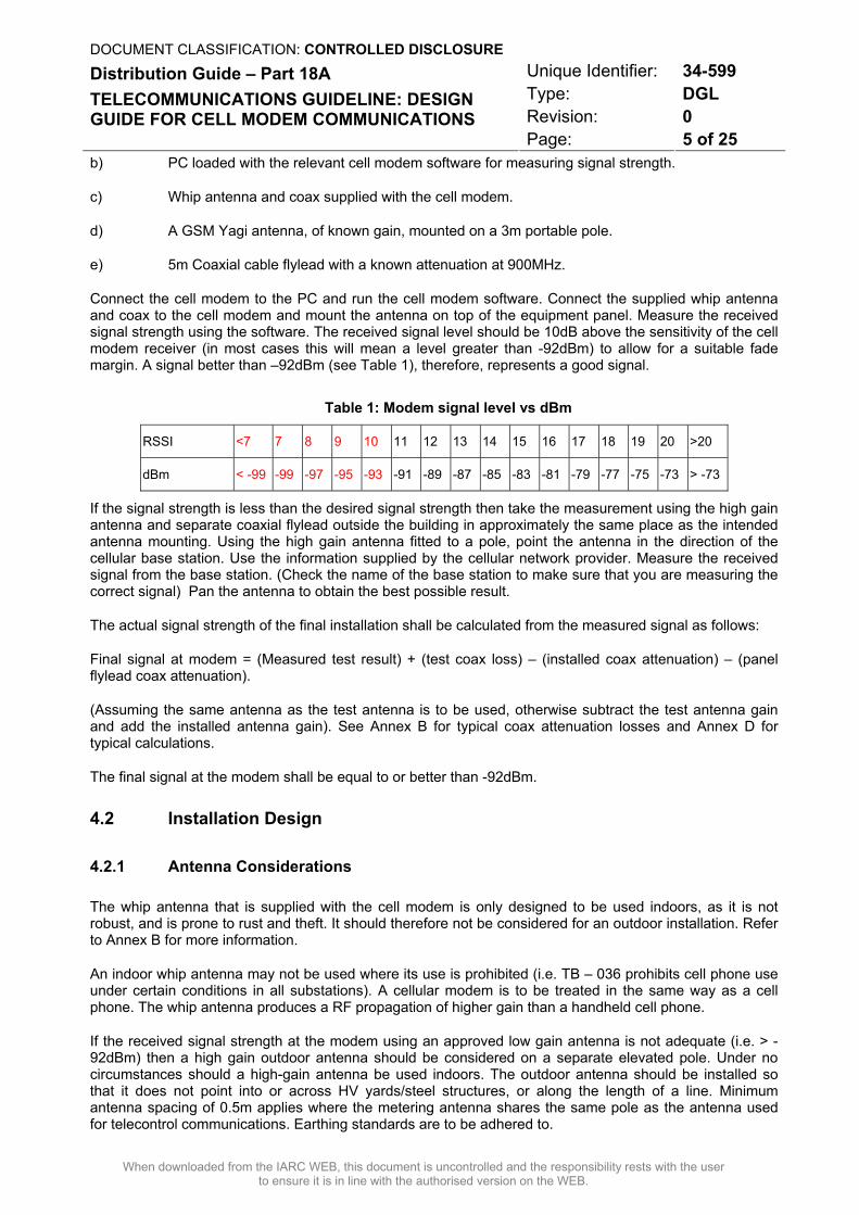
Connect the cell modem to the PC and run the cell modem software. Connect the supplied whip antenna and coax to the cell modem and mount the antenna on top of the equipment panel. Measure the received signal strength using the software. The received signal level should be 10dB above the sensitivity of the cell modem receiver (in most cases this will mean a level greater than -92dBm) to allow for a suitable fade margin. A signal better than –92dBm (see Table 1), therefore, represents a good signal.
Table 1: Modem signal level vs dBm
RSSI <7 7 8 9 10 11 12 13 14 15 16 17 18 19 20 >20
dBm < -99 -99 -97 -95 -93 -91 -89 -87 -85 -83 -81 -79 -77 -75 -73 > -73
If the signal strength is less than the desired signal strength then take the measurement using the high gain antenna and separate coaxial flylead outside the building in approximately the same place as the intended antenna mounting. Using the high gain antenna fitted to a pole, point the antenna in the direction of the cellular base station. Use the information supplied by the cellular network provider. Measure the received signal from the base station. (Check the name of the base station to make sure that you are measuring the correct signal) Pan the antenna to obtain the best possible result.
The actual signal strength of the final installation shall be calculated from the measured signal as follows:
Final signal at modem = (Measured test result) + (test coax loss) – (installed coax attenuation) – (panel flylead coax attenuation).
(Assuming the same antenna as the test antenna is to be used, otherwise subtract the test antenna gain and add the installed antenna gain). See Annex B for typical coax attenuation losses and Annex D for typical calculations.
The final signal at the modem shall be equal to or better than -92dBm.
4.2 Installation Design
4.2.1 Antenna Considerations
The whip antenna that is supplied with the cell modem is only designed to be used indoors, as it is not robust, and is prone to rust and theft. It should therefore not be considered for an outdoor installation. Refer to Annex B for more information.
An indoor whip antenna may not be used where its use is prohibited (i.e. TB – 036 prohibits cell phone use under certain conditions in all substations). A cellular modem is to be treated in the same way as a cell phone. The whip antenna produces a RF propagation of higher gain than a handheld cell phone.
If the received signal strength at the modem using an approved low gain antenna is not adequate (i.e. > -92dBm) then a high gain outdoor antenna should be considered on a separate elevated pole. Under no circumstances should a high-gain antenna be used indoors. The outdoor antenna should be installed so that it does not point into or across HV yards/steel structures, or along the length of a line. Minimum antenna spacing of 0.5m applies where the metering antenna shares the same pole as the antenna used for telecontrol communications. Earthing standards are to be adhered to.
DOCUMENT CLASSIFICATION: CONTROLLED DISCLOSURE Unique Identifier: 34-599 Type: DGL Revision: 0
Distribution Guide – Part 18A TELECOMMUNICATIONS GUIDELINE: DESIGN GUIDE FOR CELL MODEM COMMUNICATIONS
Page: 6 of 25
When downloaded from the IARC WEB, this document is uncontrolled and the responsibility rests with the user to ensure it is in line with the authorised version on the WEB.
Refer to Annex B for more information about the different types of antennas available and suitable for cell modem installations.
Wherever possible, it is recommended that only one antenna is used for multiple meters. By using the RS485 data interface a single GSM/GPRS modem can be connected to multiple meters using the same data interface.
4.2.2 Co-axial Cable Considerations
The coaxial cable supplied with the cell modem is usually RG174, which is an inexpensive and high-loss cable. It should only be used in installations where the supplied whip antenna is used.
In all other installations, the use a coaxial cable with the lowest possible loss as is practical is recommended. Refer to Annex D for information on different types of suitable coaxial cables.
Coaxial cable runs should be as short as possible and attempt should be made to limit the coaxial cable attenuation to <2dB. See Annex B for coaxial cable attenuation details.
For an external installation at a building, an earth kit on the coaxial cable must be used.
Use only approved ‘easy to fit’ high spec coaxial connectors so that the maximum total connector loss in the installation is lower than 0.5dB.
All fly leads and connectors must be made up by a company or resources with the necessary skills to do so.
4.3 Installation Guidelines
Note: The minimum bending radius of the coaxial cable is 100mm. Care must be exercised not to damage the coaxial cable when doing the installation. Care must also be taken not to damage the Telecontrol coaxial cable
4.3.1 Possible Scenarios
a) Indoor installation where the signal strength is good and the use of cell phones (indoor antennas) is not prohibited.
b) Indoor installation where the signal strength is poor but can be brought up to an acceptable level using a high gain antenna.
c) Indoor installation where the RF signal strength is good but cell phones (indoor antennas) are prohibited.
d) Outdoor installations where the RF signal strength is good.
e) Outdoor installations where the RF signal strength is poor but can be brought up to an acceptable level using a high gain antenna
4.3.2 Installation at a Building
4.3.2.1 Indoor Antenna (Scenario (a) only)
a) Mount the antenna on the top of the equipment panel
b) Feed the coax to the cell modem through a 20mm hole in the panel.
DOCUMENT CLASSIFICATION: CONTROLLED DISCLOSURE Unique Identifier: 34-599 Type: DGL Revision: 0
Distribution Guide – Part 18A TELECOMMUNICATIONS GUIDELINE: DESIGN GUIDE FOR CELL MODEM COMMUNICATIONS
Page: 7 of 25
When downloaded from the IARC WEB, this document is uncontrolled and the responsibility rests with the user to ensure it is in line with the authorised version on the WEB.
c) Ensure that the coaxial cable is protected either by a compression gland or suitable protective material that lines the hole.
d) The coaxial run must not be strapped to or run alongside power carrying cables or the earth bar.
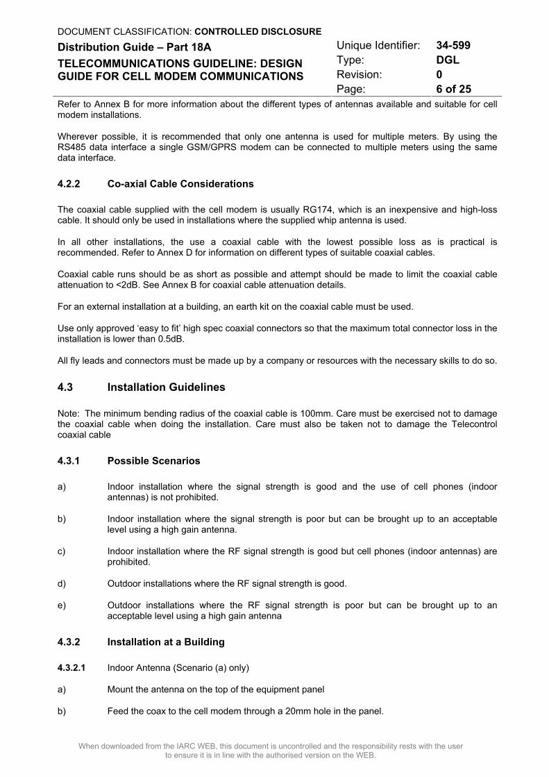
4.3.2.2 Outdoor Antenna (Scenarios (b) or (c))
Refer to Figures 1, 2 and 3.
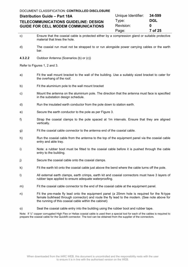
a) Fit the wall mount bracket to the wall of the building. Use a suitably sized bracket to cater for the overhang of the roof.
b) Fit the aluminium pole to the wall mount bracket
c) Mount the antenna on the aluminium pole. The direction that the antenna must face is specified in the substation design schedule.
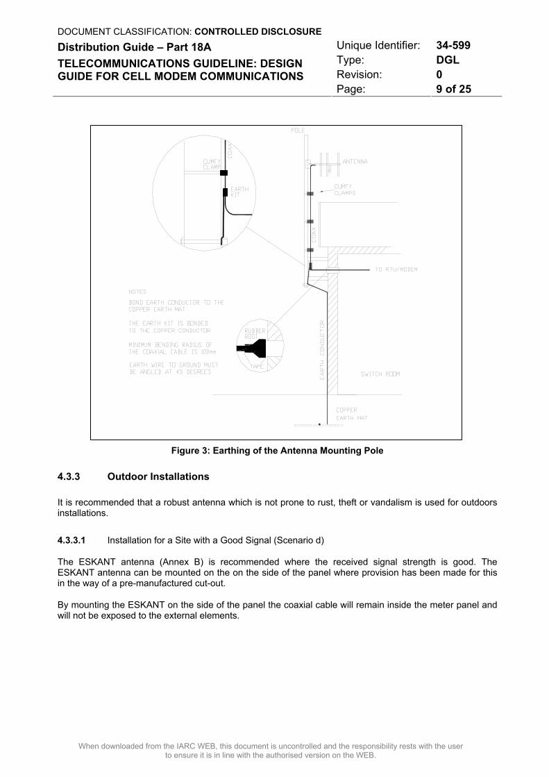
d) Run the insulated earth conductor from the pole down to station earth.
e) Secure the earth conductor to the pole as per Figure 3.
f) Strap the coaxial clamps to the pole spaced at 1m intervals. Ensure that they are aligned vertically.
g) Fit the coaxial cable connector to the antenna end of the coaxial cable.
h) Run the coaxial cable from the antenna to the top of the equipment panel via the coaxial cable entry and able tray.
i) Note: a rubber boot must be fitted to the coaxial cable before it is pushed through the cable entry to the building.
j) Secure the coaxial cable onto the coaxial clamps.
k) Fit the earth kit onto the coaxial cable just above the bend where the cable turns off the pole.
l) All external earth clamps, earth crimps, earth kit and coaxial connectors must have 3 layers of rubber tape applied to ensure adequate waterproofing.
m) Fit the coaxial cable connector to the end of the coaxial cable at the equipment panel.
n) Fit the pre-made fly lead onto the equipment panel (a 20mm hole is required for the N-type female bulkhead through connector) and route the fly lead to the modem. (See note above for the running of this coaxial cable within the cabinet)
o) Seal the coaxial cable entry into the building using the rubber boot and rubber tape. Note: If ½” copper corrugated High Flex or Heliax coaxial cable is used then a special tool for each of the cables is required to prepare the coaxial cable for the Quickfit connector. The tool can be obtained from the supplier of the connectors.
DOCUMENT CLASSIFICATION: CONTROLLED DISCLOSURE Unique Identifier: 34-599 Type: DGL Revision: 0
Distribution Guide – Part 18A TELECOMMUNICATIONS GUIDELINE: DESIGN GUIDE FOR CELL MODEM COMMUNICATIONS
Page: 8 of 25
When downloaded from the IARC WEB, this document is uncontrolled and the responsibility rests with the user to ensure it is in line with the authorised version on the WEB.
Figure 1: Concept Drawing for Installation on a Building
Figure 2: Antenna Mounting on a Building
DOCUMENT CLASSIFICATION: CONTROLLED DISCLOSURE Unique Identifier: 34-599 Type: DGL Revision: 0
Distribution Guide – Part 18A TELECOMMUNICATIONS GUIDELINE: DESIGN GUIDE FOR CELL MODEM COMMUNICATIONS
Page: 9 of 25
When downloaded from the IARC WEB, this document is uncontrolled and the responsibility rests with the user to ensure it is in line with the authorised version on the WEB.
Figure 3: Earthing of the Antenna Mounting Pole
4.3.3 Outdoor Installations
It is recommended that a robust antenna which is not prone to rust, theft or vandalism is used for outdoors installations.
4.3.3.1 Installation for a Site with a Good Signal (Scenario d)
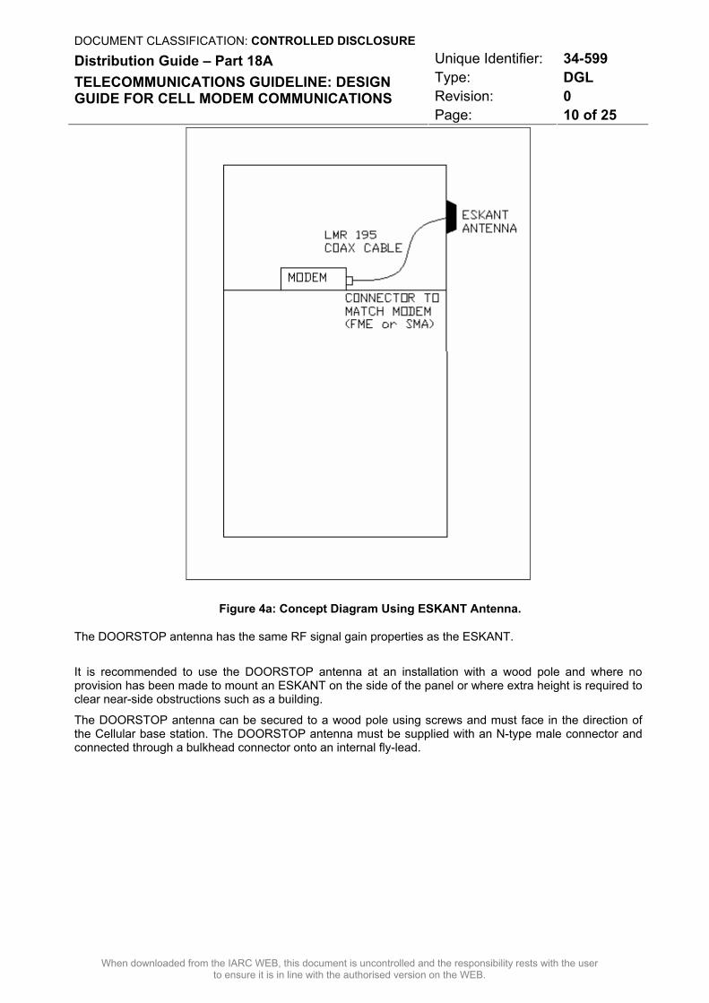
The ESKANT antenna (Annex B) is recommended where the received signal strength is good. The ESKANT antenna can be mounted on the on the side of the panel where provision has been made for this in the way of a pre-manufactured cut-out.
By mounting the ESKANT on the side of the panel the coaxial cable will remain inside the meter panel and will not be exposed to the external elements.
DOCUMENT CLASSIFICATION: CONTROLLED DISCLOSURE Unique Identifier: 34-599 Type: DGL Revision: 0
Distribution Guide – Part 18A TELECOMMUNICATIONS GUIDELINE: DESIGN GUIDE FOR CELL MODEM COMMUNICATIONS
Page: 10 of 25
When downloaded from the IARC WEB, this document is uncontrolled and the responsibility rests with the user to ensure it is in line with the authorised version on the WEB.
Figure 4a: Concept Diagram Using ESKANT Antenna.
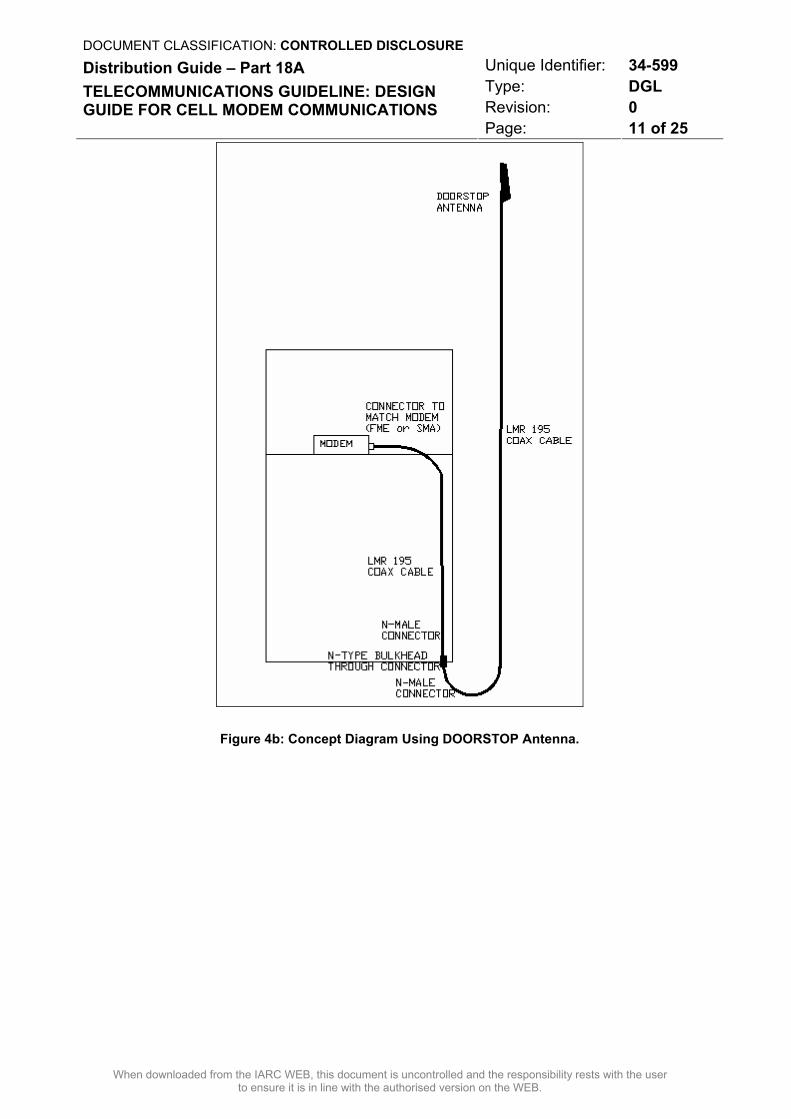
The DOORSTOP antenna has the same RF signal gain properties as the ESKANT.
It is recommended to use the DOORSTOP antenna at an installation with a wood pole and where no provision has been made to mount an ESKANT on the side of the panel or where extra height is required to clear near-side obstructions such as a building.
The DOORSTOP antenna can be secured to a wood pole using screws and must face in the direction of the Cellular base station. The DOORSTOP antenna must be supplied with an N-type male connector and connected through a bulkhead connector onto an internal fly-lead.
DOCUMENT CLASSIFICATION: CONTROLLED DISCLOSURE Unique Identifier: 34-599 Type: DGL Revision: 0
Distribution Guide – Part 18A TELECOMMUNICATIONS GUIDELINE: DESIGN GUIDE FOR CELL MODEM COMMUNICATIONS
Page: 11 of 25
When downloaded from the IARC WEB, this document is uncontrolled and the responsibility rests with the user to ensure it is in line with the authorised version on the WEB.
Figure 4b: Concept Diagram Using DOORSTOP Antenna.
DOCUMENT CLASSIFICATION: CONTROLLED DISCLOSURE Unique Identifier: 34-599 Type: DGL Revision: 0
Distribution Guide – Part 18A TELECOMMUNICATIONS GUIDELINE: DESIGN GUIDE FOR CELL MODEM COMMUNICATIONS
Page: 12 of 25
When downloaded from the IARC WEB, this document is uncontrolled and the responsibility rests with the user to ensure it is in line with the authorised version on the WEB.
4.3.3.2 Installation for a Site with a Poor Signal (Scenario e)
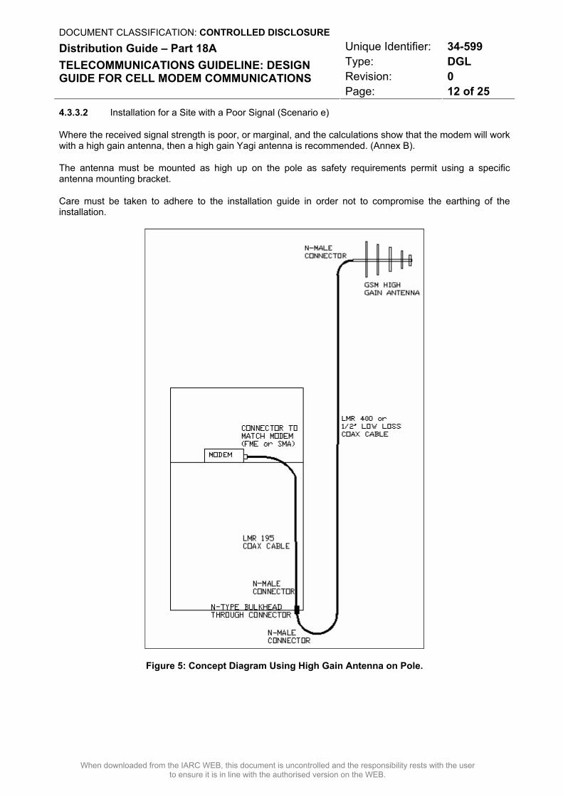
Where the received signal strength is poor, or marginal, and the calculations show that the modem will work with a high gain antenna, then a high gain Yagi antenna is recommended. (Annex B).
The antenna must be mounted as high up on the pole as safety requirements permit using a specific antenna mounting bracket.
Care must be taken to adhere to the installation guide in order not to compromise the earthing of the installation.
Figure 5: Concept Diagram Using High Gain Antenna on Pole.
DOCUMENT CLASSIFICATION: CONTROLLED DISCLOSURE Unique Identifier: 34-599 Type: DGL Revision: 0
Distribution Guide – Part 18A TELECOMMUNICATIONS GUIDELINE: DESIGN GUIDE FOR CELL MODEM COMMUNICATIONS
Page: 13 of 25
When downloaded from the IARC WEB, this document is uncontrolled and the responsibility rests with the user to ensure it is in line with the authorised version on the WEB.
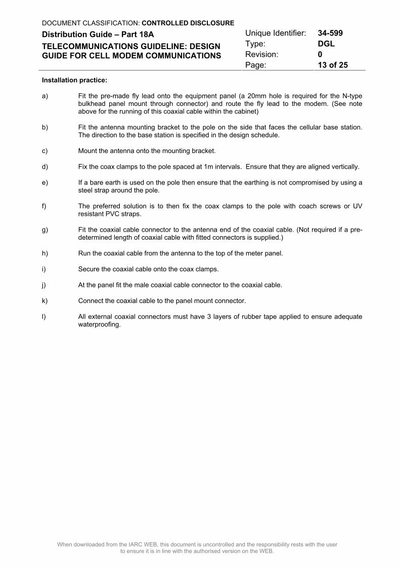
Installation practice:
a) Fit the pre-made fly lead onto the equipment panel (a 20mm hole is required for the N-type bulkhead panel mount through connector) and route the fly lead to the modem. (See note above for the running of this coaxial cable within the cabinet)
b) Fit the antenna mounting bracket to the pole on the side that faces the cellular base station. The direction to the base station is specified in the design schedule.
c) Mount the antenna onto the mounting bracket.
d) Fix the coax clamps to the pole spaced at 1m intervals. Ensure that they are aligned vertically.
e) If a bare earth is used on the pole then ensure that the earthing is not compromised by using a steel strap around the pole.
f) The preferred solution is to then fix the coax clamps to the pole with coach screws or UV resistant PVC straps.
g) Fit the coaxial cable connector to the antenna end of the coaxial cable. (Not required if a pre-determined length of coaxial cable with fitted connectors is supplied.)
h) Run the coaxial cable from the antenna to the top of the meter panel.
i) Secure the coaxial cable onto the coax clamps.
j) At the panel fit the male coaxial cable connector to the coaxial cable.
k) Connect the coaxial cable to the panel mount connector.
l) All external coaxial connectors must have 3 layers of rubber tape applied to ensure adequate waterproofing.
DOCUMENT CLASSIFICATION: CONTROLLED DISCLOSURE Unique Identifier: 34-599 Type: DGL Revision: 0
Distribution Guide – Part 18A TELECOMMUNICATIONS GUIDELINE: DESIGN GUIDE FOR CELL MODEM COMMUNICATIONS
Page: 14 of 25
When downloaded from the IARC WEB, this document is uncontrolled and the responsibility rests with the user to ensure it is in line with the authorised version on the WEB.
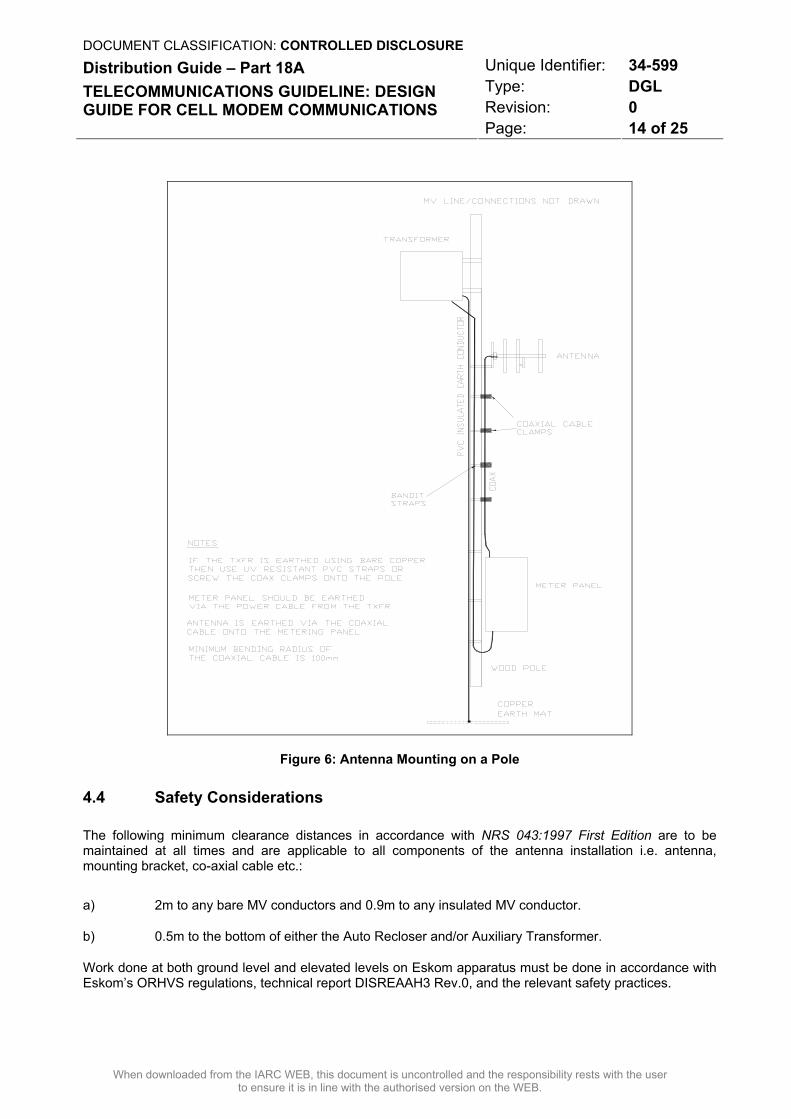
Figure 6: Antenna Mounting on a Pole
4.4 Safety Considerations
The following minimum clearance distances in accordance with NRS 043:1997 First Edition are to be maintained at all times and are applicable to all components of the antenna installation i.e. antenna, mounting bracket, co-axial cable etc.:
a) 2m to any bare MV conductors and 0.9m to any insulated MV conductor.
b) 0.5m to the bottom of either the Auto Recloser and/or Auxiliary Transformer.
Work done at both ground level and elevated levels on Eskom apparatus must be done in accordance with Eskom’s ORHVS regulations, technical report DISREAAH3 Rev.0, and the relevant safety practices.
DOCUMENT CLASSIFICATION: CONTROLLED DISCLOSURE Unique Identifier: 34-599 Type: DGL Revision: 0
Distribution Guide – Part 18A TELECOMMUNICATIONS GUIDELINE: DESIGN GUIDE FOR CELL MODEM COMMUNICATIONS
Page: 15 of 25
When downloaded from the IARC WEB, this document is uncontrolled and the responsibility rests with the user to ensure it is in line with the authorised version on the WEB.
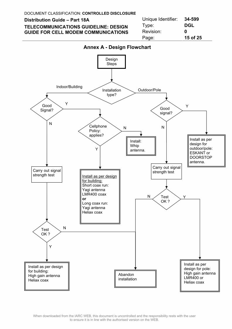
Annex A - Design Flowchart
Design Steps
Installation type?
Good Signal? Good
signal?
Test OK ?
Carry out signal strength test
Install as per design for building: High gain antenna Heliax coax
Install as per design for building: Short coax run: Yagi antenna LMR400 coax or Long coax run: Yagi antenna Heliax coax
Install: Whip antenna.
Abandon installation
Cellphone Policy: applies?
Carry out signal strength test
Install as per design for pole: High gain antennaLMR400 or Heliax coax
Install as per design for outdoor/pole: ESKANT or DOORSTOP antenna.
Test OK ?
Y
N
Y
Y
Y
Y
N N
N
N
Indoor/Building Outdoor/Pole
DOCUMENT CLASSIFICATION: CONTROLLED DISCLOSURE Unique Identifier: 34-599 Type: DGL Revision: 0
Distribution Guide – Part 18A TELECOMMUNICATIONS GUIDELINE: DESIGN GUIDE FOR CELL MODEM COMMUNICATIONS
Page: 16 of 25
When downloaded from the IARC WEB, this document is uncontrolled and the responsibility rests with the user to ensure it is in line with the authorised version on the WEB.
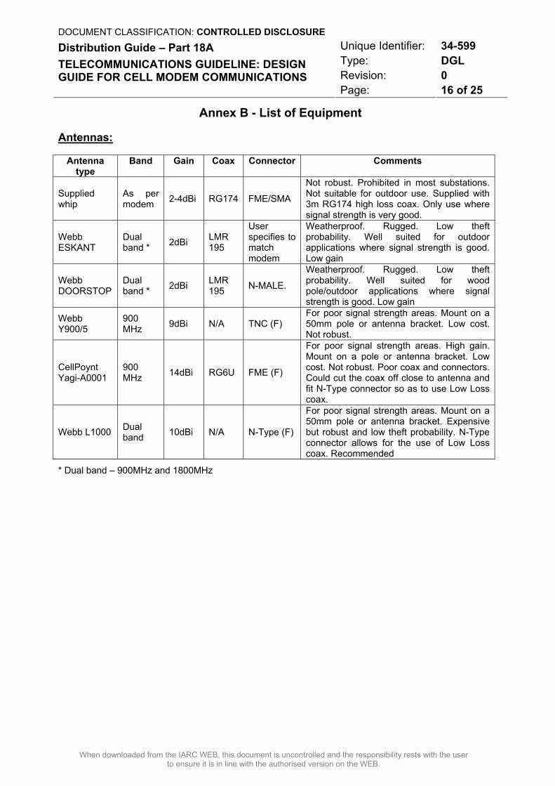
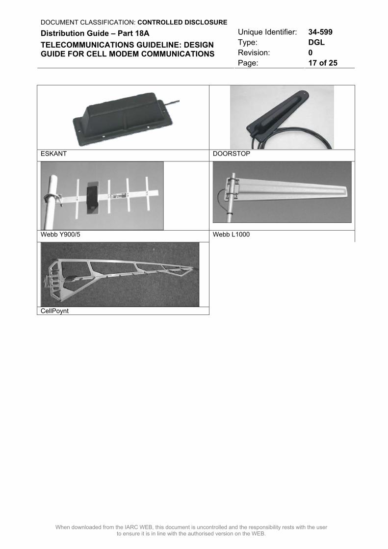
Annex B - List of Equipment
Antennas:
Antenna type
Band Gain Coax Connector Comments
Supplied whip
As per modem 2-4dBi RG174 FME/SMA
Not robust. Prohibited in most substations. Not suitable for outdoor use. Supplied with 3m RG174 high loss coax. Only use where signal strength is very good.
Webb ESKANT
Dual band * 2dBi LMR
195
User specifies to match modem
Weatherproof. Rugged. Low theft probability. Well suited for outdoor applications where signal strength is good. Low gain
Webb DOORSTOP
Dual band * 2dBi LMR
195 N-MALE.
Weatherproof. Rugged. Low theft probability. Well suited for wood pole/outdoor applications where signal strength is good. Low gain
Webb Y900/5
900 MHz 9dBi N/A TNC (F)
For poor signal strength areas. Mount on a 50mm pole or antenna bracket. Low cost. Not robust.
CellPoynt Yagi-A0001
900 MHz 14dBi RG6U FME (F)
For poor signal strength areas. High gain. Mount on a pole or antenna bracket. Low cost. Not robust. Poor coax and connectors. Could cut the coax off close to antenna and fit N-Type connector so as to use Low Loss coax.
Webb L1000 Dual band 10dBi N/A N-Type (F)
For poor signal strength areas. Mount on a 50mm pole or antenna bracket. Expensive but robust and low theft probability. N-Type connector allows for the use of Low Loss coax. Recommended
* Dual band – 900MHz and 1800MHz
DOCUMENT CLASSIFICATION: CONTROLLED DISCLOSURE Unique Identifier: 34-599 Type: DGL Revision: 0
Distribution Guide – Part 18A TELECOMMUNICATIONS GUIDELINE: DESIGN GUIDE FOR CELL MODEM COMMUNICATIONS
Page: 17 of 25
When downloaded from the IARC WEB, this document is uncontrolled and the responsibility rests with the user to ensure it is in line with the authorised version on the WEB.
ESKANT DOORSTOP
Webb Y900/5 Webb L1000
CellPoynt
DOCUMENT CLASSIFICATION: CONTROLLED DISCLOSURE Unique Identifier: 34-599 Type: DGL Revision: 0
Distribution Guide – Part 18A TELECOMMUNICATIONS GUIDELINE: DESIGN GUIDE FOR CELL MODEM COMMUNICATIONS
Page: 18 of 25
When downloaded from the IARC WEB, this document is uncontrolled and the responsibility rests with the user to ensure it is in line with the authorised version on the WEB.
Coaxial Cables:
Coax Type
Attenuation at 900MHz (Db/100m)
Max. length
(m)
Total Loss (Db) Comments
RG174 98 1.0 0.98 Supplied on most cell modem whip antennas. Very high loss. Not recommended.
RG-58 54 2.0 1.08 Can be supplied with ESKANT antenna but not preferred. Keep as short as possible.
LMR-195 36 2.5 0.90
Supplied with ESKANT & DOORSTOP antennas. Flexible. Good screening. Preferred for coax tails inside panel
LMR-400 12.7 7.5 0.95 Flexible, low cost. Preferred for installation on wood poles.
½” High Flex 11.2 9.0 1.01
Alternative to LMR400. Costs more. Can take high quality connectors. Preferred in marginal signal areas. Can only use N-type connector.
½” Heliax 7.2 15.0 1.08
Preferred for installations in a building where longer coax runs to an external pole or mast are required. Can only use N-type connector.
Maximum length is a recommendation only to limit attenuation to approximately 1dB for the coax run.
Every attempt must be made to limit coaxial cable losses and it is recommended not to exceed 2dB coaxial cable attenuation for the entire installation.
For distances greater than 15m use the ½” Heliax up to a recommended maximum length of 30m.
Coaxial cable clamps to fit specified coaxial cable.
Use 30mm PVC conduit where the coax run is inside the cable trench.
Use PVC cable trunking for runs up the wall.
Overhead racking or cable tray is the preferred way to run the coaxial cable from the panel to the outer wall.
Cable entry into the building: 50mm diameter PVC pipe protruding 50mm on the outer side of the wall.
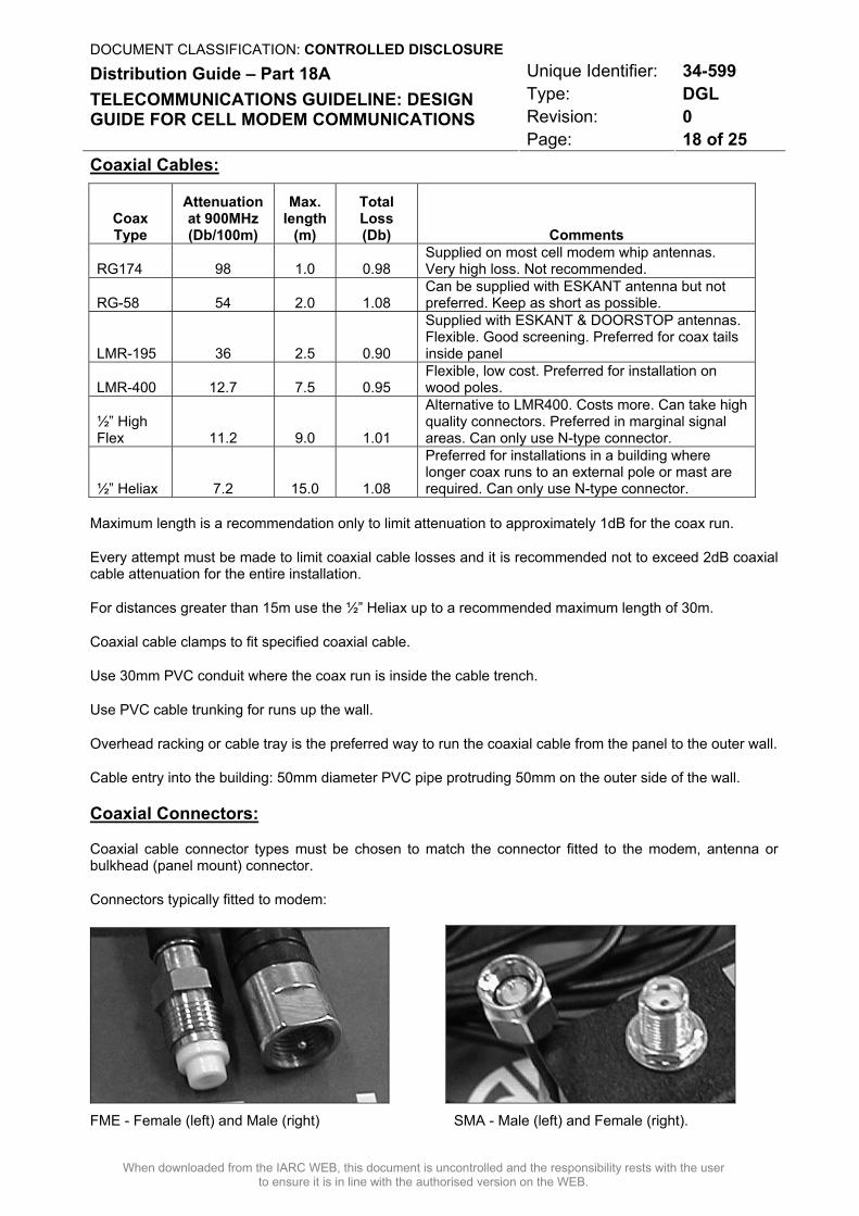
Coaxial Connectors:
Coaxial cable connector types must be chosen to match the connector fitted to the modem, antenna or bulkhead (panel mount) connector.
Connectors typically fitted to modem:
FME - Female (left) and Male (right) SMA - Male (left) and Female (right).
DOCUMENT CLASSIFICATION: CONTROLLED DISCLOSURE Unique Identifier: 34-599 Type: DGL Revision: 0
Distribution Guide – Part 18A TELECOMMUNICATIONS GUIDELINE: DESIGN GUIDE FOR CELL MODEM COMMUNICATIONS
Page: 19 of 25
When downloaded from the IARC WEB, this document is uncontrolled and the responsibility rests with the user to ensure it is in line with the authorised version on the WEB.
Connectors used inside the panel or indoors may be made off using a crimp connection.
All connectors used outdoors must be a compression type connector or a crimp connection with a high quality sealing sleeve which is guaranteed to prevent the ingress of moisture. Use weatherproof tape on all outdoor connectors.
For RG-58, LMR-195 or LMR-400 coaxial cable it is recommended to order the correct lengths with the relevant connectors already fitted.
For ½” High Flex and ½” Heliax a quickfit N-type connector can be fitted on site. Note a special stripping tool will be required to carry out the work.
A suitable N-type to TNC adaptor may be required at the antenna end for some makes of Yagi.
Pre-made fly lead inside meter panel:
Use LMR-195 coaxial cable fitted with the correct connector to match the modem and external coax connectors.
Use an FME or SMA connector on the modem side and a N-type female panel mount connector (keep as short as possible).
Mounting brackets for Yagi antennas on the side of a building:
Use a pre-made rugged mounting bracket as offered by antenna suppliers.
Mounting poles: 5m Aluminium pole 50mm diameter 5mm wall thickness
Mounting brackets for Yagi antenna mounting on wood poles:
Have a suitable bracket made up according the suggested design in Annex E.
Earth kits:
Supplier to provide suitable earth kit for ½” HF or Heliax coaxial cable.
Use 25mm2 insulated green and yellow wire for connections to earth.
DOCUMENT CLASSIFICATION: CONTROLLED DISCLOSURE Unique Identifier: 34-599 Type: DGL Revision: 0
Distribution Guide – Part 18A TELECOMMUNICATIONS GUIDELINE: DESIGN GUIDE FOR CELL MODEM COMMUNICATIONS
Page: 20 of 25
When downloaded from the IARC WEB, this document is uncontrolled and the responsibility rests with the user to ensure it is in line with the authorised version on the WEB.
Annex C - Technical Data of a Typical Cell Modem
Most cell modems use the Wavecom transceiver module.
• Transmitter RF output power: 2W
• Receiver Sensitivity: –102dBm
• External connections vary between the products of the different manufacturers.
• Data: RS232 - 9 pin or 25 pin D-type connector.
• RF Connector: Could be any of the following:- FME male, FME female or SMA female. Most manufacturers are standardising on the SMA connector.
• Power Supply: External AC adaptor or 220/110V AC internal PSU. (Some modems can be ordered with a 12V DC supply)
DOCUMENT CLASSIFICATION: CONTROLLED DISCLOSURE Unique Identifier: 34-599 Type: DGL Revision: 0
Distribution Guide – Part 18A TELECOMMUNICATIONS GUIDELINE: DESIGN GUIDE FOR CELL MODEM COMMUNICATIONS
Page: 21 of 25
When downloaded from the IARC WEB, this document is uncontrolled and the responsibility rests with the user to ensure it is in line with the authorised version on the WEB.
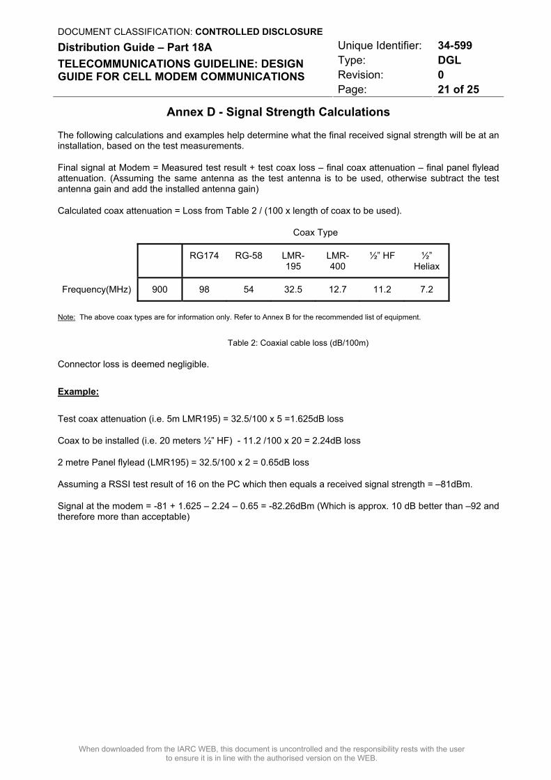
Annex D - Signal Strength Calculations
The following calculations and examples help determine what the final received signal strength will be at an installation, based on the test measurements.
Final signal at Modem = Measured test result + test coax loss – final coax attenuation – final panel flylead attenuation. (Assuming the same antenna as the test antenna is to be used, otherwise subtract the test antenna gain and add the installed antenna gain)
Calculated coax attenuation = Loss from Table 2 / (100 x length of coax to be used).
Coax Type
RG174 RG-58 LMR-195
LMR-400
½” HF ½” Heliax
Frequency(MHz) 900 98 54 32.5 12.7 11.2 7.2
Note: The above coax types are for information only. Refer to Annex B for the recommended list of equipment.
Table 2: Coaxial cable loss (dB/100m)
Connector loss is deemed negligible.
Example:
Test coax attenuation (i.e. 5m LMR195) = 32.5/100 x 5 =1.625dB loss
Coax to be installed (i.e. 20 meters ½” HF) - 11.2 /100 x 20 = 2.24dB loss
2 metre Panel flylead (LMR195) = 32.5/100 x 2 = 0.65dB loss
Assuming a RSSI test result of 16 on the PC which then equals a received signal strength = –81dBm.
Signal at the modem = -81 + 1.625 – 2.24 – 0.65 = -82.26dBm (Which is approx. 10 dB better than –92 and therefore more than acceptable)
DOCUMENT CLASSIFICATION: CONTROLLED DISCLOSURE Unique Identifier: 34-599 Type: DGL Revision: 0
Distribution Guide – Part 18A TELECOMMUNICATIONS GUIDELINE: DESIGN GUIDE FOR CELL MODEM COMMUNICATIONS
Page: 22 of 25
When downloaded from the IARC WEB, this document is uncontrolled and the responsibility rests with the user to ensure it is in line with the authorised version on the WEB.
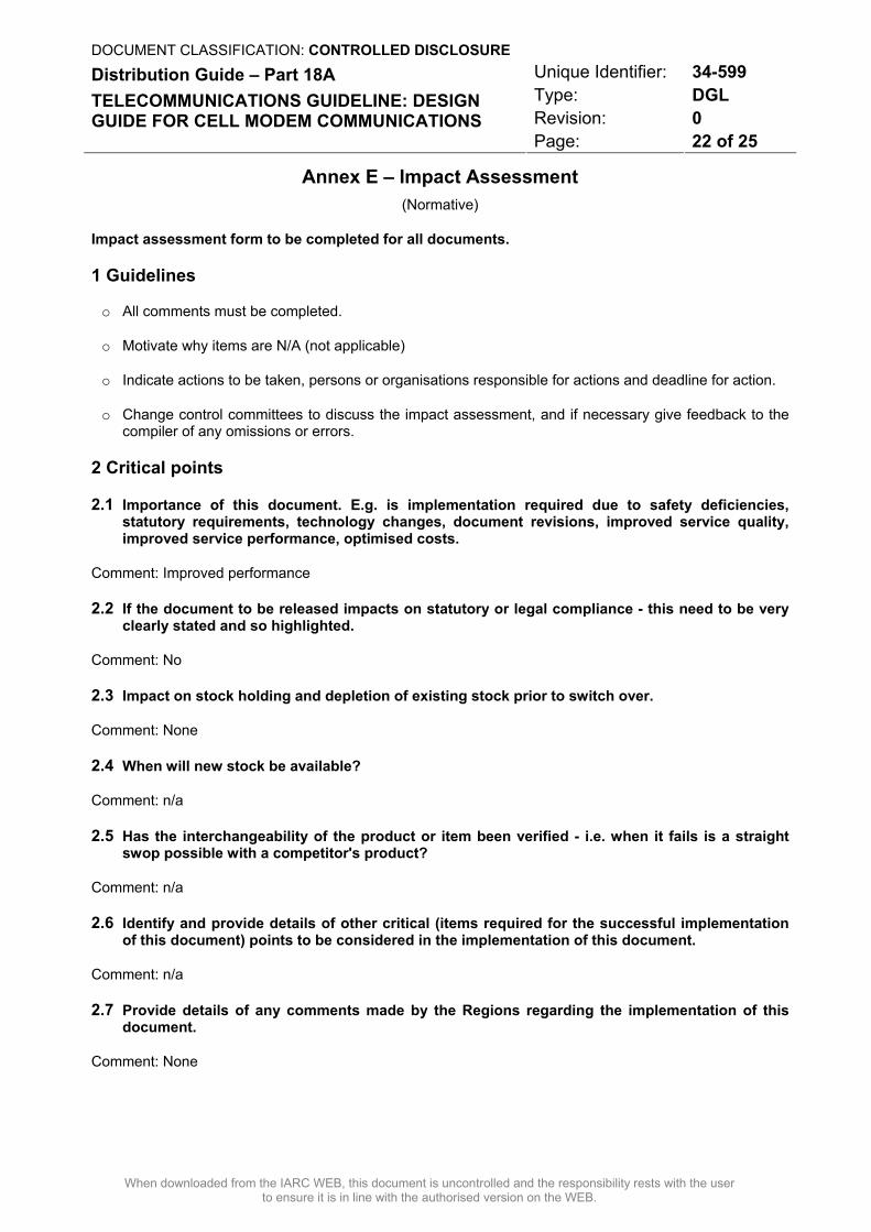
Annex E – Impact Assessment (Normative)
Impact assessment form to be completed for all documents.
1 Guidelines
o All comments must be completed.
o Motivate why items are N/A (not applicable)
o Indicate actions to be taken, persons or organisations responsible for actions and deadline for action.
o Change control committees to discuss the impact assessment, and if necessary give feedback to the compiler of any omissions or errors.
2 Critical points
2.1 Importance of this document. E.g. is implementation required due to safety deficiencies, statutory requirements, technology changes, document revisions, improved service quality, improved service performance, optimised costs.
Comment: Improved performance
2.2 If the document to be released impacts on statutory or legal compliance - this need to be very clearly stated and so highlighted.
Comment: No
2.3 Impact on stock holding and depletion of existing stock prior to switch over.
Comment: None
2.4 When will new stock be available?
Comment: n/a
2.5 Has the interchangeability of the product or item been verified - i.e. when it fails is a straight swop possible with a competitor's product?
Comment: n/a
2.6 Identify and provide details of other critical (items required for the successful implementation of this document) points to be considered in the implementation of this document.
Comment: n/a
2.7 Provide details of any comments made by the Regions regarding the implementation of this document.
Comment: None
DOCUMENT CLASSIFICATION: CONTROLLED DISCLOSURE Unique Identifier: 34-599 Type: DGL Revision: 0
Distribution Guide – Part 18A TELECOMMUNICATIONS GUIDELINE: DESIGN GUIDE FOR CELL MODEM COMMUNICATIONS
Page: 23 of 25
When downloaded from the IARC WEB, this document is uncontrolled and the responsibility rests with the user to ensure it is in line with the authorised version on the WEB.
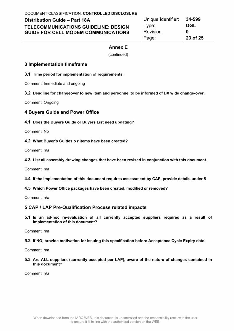
Annex E
(continued)
3 Implementation timeframe
3.1 Time period for implementation of requirements.
Comment: Immediate and ongoing
3.2 Deadline for changeover to new item and personnel to be informed of DX wide change-over.
Comment: Ongoing
4 Buyers Guide and Power Office
4.1 Does the Buyers Guide or Buyers List need updating?
Comment: No
4.2 What Buyer’s Guides o r items have been created?
Comment: n/a
4.3 List all assembly drawing changes that have been revised in conjunction with this document.
Comment: n/a
4.4 If the implementation of this document requires assessment by CAP, provide details under 5
4.5 Which Power Office packages have been created, modified or removed?
Comment: n/a
5 CAP / LAP Pre-Qualification Process related impacts
5.1 Is an ad-hoc re-evaluation of all currently accepted suppliers required as a result of implementation of this document?
Comment: n/a
5.2 If NO, provide motivation for issuing this specification before Acceptance Cycle Expiry date.
Comment: n/a
5.3 Are ALL suppliers (currently accepted per LAP), aware of the nature of changes contained in this document?
Comment: n/a
DOCUMENT CLASSIFICATION: CONTROLLED DISCLOSURE Unique Identifier: 34-599 Type: DGL Revision: 0
Distribution Guide – Part 18A TELECOMMUNICATIONS GUIDELINE: DESIGN GUIDE FOR CELL MODEM COMMUNICATIONS
Page: 24 of 25
When downloaded from the IARC WEB, this document is uncontrolled and the responsibility rests with the user to ensure it is in line with the authorised version on the WEB.
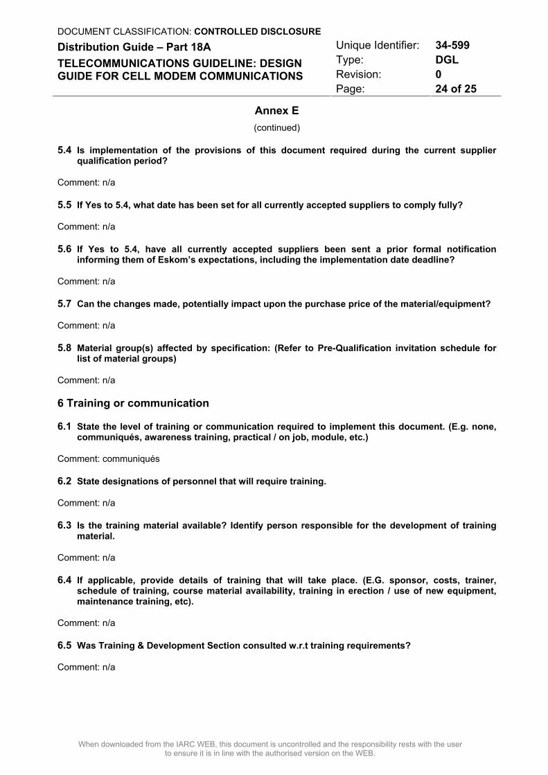
Annex E (continued)
5.4 Is implementation of the provisions of this document required during the current supplier qualification period?
Comment: n/a
5.5 If Yes to 5.4, what date has been set for all currently accepted suppliers to comply fully?
Comment: n/a
5.6 If Yes to 5.4, have all currently accepted suppliers been sent a prior formal notification informing them of Eskom’s expectations, including the implementation date deadline?
Comment: n/a
5.7 Can the changes made, potentially impact upon the purchase price of the material/equipment?
Comment: n/a
5.8 Material group(s) affected by specification: (Refer to Pre-Qualification invitation schedule for list of material groups)
Comment: n/a
6 Training or communication
6.1 State the level of training or communication required to implement this document. (E.g. none, communiqués, awareness training, practical / on job, module, etc.)
Comment: communiqués
6.2 State designations of personnel that will require training.
Comment: n/a
6.3 Is the training material available? Identify person responsible for the development of training material.
Comment: n/a
6.4 If applicable, provide details of training that will take place. (E.G. sponsor, costs, trainer, schedule of training, course material availability, training in erection / use of new equipment, maintenance training, etc).
Comment: n/a
6.5 Was Training & Development Section consulted w.r.t training requirements?
Comment: n/a
DOCUMENT CLASSIFICATION: CONTROLLED DISCLOSURE Unique Identifier: 34-599 Type: DGL Revision: 0
Distribution Guide – Part 18A TELECOMMUNICATIONS GUIDELINE: DESIGN GUIDE FOR CELL MODEM COMMUNICATIONS
Page: 25 of 25
When downloaded from the IARC WEB, this document is uncontrolled and the responsibility rests with the user to ensure it is in line with the authorised version on the WEB.
Annex E (continued)
7 Special tools, equipment, software
7.1 What special tools, equipment, software, etc will need to be purchased by the Region to effectively implement?
Comment: none
7.2 Are there stock numbers available for the new equipment?
Comment: n/a
7.3 What will be the costs of these special tools, equipment, software?
8 Finances
8.1 What total costs would the Regions be required to incur in implementing this document? Identify all cost activities associated with implementation, e.g. labour, training, tooling, stock, obsolescence
Comment: n/a
…None………………………………………………………………………………………………………………….
……………………………………………………………………………………………………………………….
……………………………………………………………………………………………………………………….
Impact assessment completed by:
Name: R Westwood
Designation: Telecomms Contracts Senior Technologist