teleco catalog
TRANSCRIPT

Contents
Telco, the Original
A well established high tech Danish enterprise, formed
in 1975, has become one of the most sought after high
performance sensor manufacturers in the world. Telco’s
global success is the result of many years of listening to the
experts – our customers.
All Telco sensors are manufactured in-house by
skilled employees together with advanced automated
production equipment. The strictest quality standards
guarantee that both components and the finished product
have undergone comprehensive quality inspections at
each production stage achieving unmatched technical
superiority.
Telco’s wide range of sensors are typically used for
counting, sorting, measuring, positioning and detecting
within, but not limited to, the industries of steel, wood,
packaging, material handling, bottling, agriculture, car
wash, elevators and automatic doors. All Telco sensors are
tolerant of hostile environments and are consequently the
most versatile on the market with a 3 year world-wide
warranty.
Telco is proudly represented by its own renowned
subsidiaries and qualified representatives world-wide who
provide 24 hour service with stock, just in time delivery,
technical and on site application support.
Contact your local Telco representative today – seeing
is believing!
Remote Photoelectric Systems
� Remote Sensors .................................................... page 3
� PA 01 ............................................................................ page 7
� PA 09 ............................................................................ page 9
� PA 10 ............................................................................ page 11
� PA 11 ............................................................................ page 13
� MPA 21 ........................................................................ page 15
� MPA 41 ........................................................................ page 17
� MPA 81 ........................................................................ page 19
Self Contained Photoelectric Systems
� Spacemaster 3000 .............................................. page 21
� Spacemaster 6000 .............................................. page 25
� Spacemaster 7000 .............................................. page 29
� Spacemaster 8000 .............................................. page 33
� Power Packs ............................................................ page 37
General
� Accessories ............................................................ page 39
� Fibre Optics .............................................................. page 41
� Glossary .................................................................... page 45
1
Telco_2000_catalogue 5/1/1904 4:01 pm Page 1

2
Telco_2000_catalogue 5/1/1904 4:01 pm Page 2

Remote Sensor Series
Description
� Operation mode and max sensing range:Thru beam: 0-70 mDiffuse proximity: 0-3,5 m
� Optional sensor monitor LED
� Wide variety of housings
� High tolerance to hostile environments
� Cable or plug connections
The remote sensor series, which consists of a transmitter LT and receiver
LR, is made to operate in conjunction with a Telco photoelectric amplifier
from the PA or MPA programmes.
The remote sensors are available in a wide range of housings, with either
cable or plug connection, and may be used in thru beam or diffuse
proximity mode.
The series is available with optional power-(LR) and output-(LT) monitor
LEDs for use with any Telco photoelectric amplifier which has the sensor
LED drive feature incorporated.
3
Technical Data
LT LR
Transmitter Diode Ga Al As, (880 nm) –
Photo Transistor – Silicon NPN
Cable Ø 4mm PVC Sleeves 2 x 0,25 mm2 1 x 0,25 mm2 + shield
Min. cable bending radius 45 mm
Environmental Data
Vibration 10 – 55 Hz, 0,5 mm
Shock 30 g
Light immunity, @ 20° incidence 101 Series >50 000 lux 100 Series >80 000 lux110/120 Series >100 000 lux
Temperature, operation – 25 to +65 °C
Temperature, storage – 40 to +80 °C
Sealing Class IP 67
Approvals a
Telco_2000_catalogue 5/1/1904 4:01 pm Page 3

Rec
eive
rTr
ansm
itte
rRemote Sensor Series
4
PolycarbonateØ10 LT 100 AP38 5 LT 100 AP38 15 LT 100 AP38 T3 –
+/– 6°LT 100 TP38 5 LT 100 TP38 15 LT 100 TP38 T3 –
Nickel Plated Brass M12 x 1 LT 100 TB38 5 LT 100 TB38 15 LT 100 TB38 T3 LT 100 TB58 J
100Stainless Steel LT 100 TS38 5 LT 100 TS38 15 LT 100 TS38 T3 LT 100 TS58 J
PolycarbonateØ10 LR 100 AP38 5 LR 100 AP38 15 LR 100 AP38 T3 –
+/– 9°LR 100 TP38 5 LR 100 TP38 15 LR 100 TP38 T3 –
Nickel Plated Brass M12 x 1 LR 100 TB38 5 LR 100 TB38 15 LR 100 TB38 T3 LR 100 TB58 J
Stainless Steel LR 100 TS38 5 LR 100 TS38 15 LR 100 TS38 T3 LR 100 TS58 J
Rec
eive
rTr
ansm
itte
r
PolycarbonateØ10 LT 110 AP38 5 LT 110 AP38 15 LT 110 AP38 T3 –
+/– 8°LT 110 TP38 5 LT 110 TP38 15 LT 110 TP38 T3 –
Nickel Plated Brass M12 x 1 LT 110 TB38 5 LT 110 TB38 15 LT 110 TB38 T3 LT 110 TB58 J
110Stainless Steel LT 110 TS38 5 LT 110 TS38 15 LT 110 TS38 T3 LT 110 TS58 J
PolycarbonateØ10 LR 110 AP38 5 LR 110 AP38 15 LR 110 AP38 T3 –
+/– 3°LR 110 TP38 5 LR 110 TP38 15 LR 110 TP38 T3 –
Nickel Plated Brass M12 x 1 LR 110 TB38 5 LR 110 TB38 15 LR 110 TB38 T3 LR 110 TB58 J
Stainless Steel LR 110 TS38 5 LR 110 TS38 15 LR 110 TS38 T3 LR 110 TS58 J
Note: If the applicable amplifier has sensor LED-drive, add ‘L’ after the series number for sensor monitor LED eg. LT/LR 101L AP25 5.Sensors marked * do not have this optional feature. Photo amplifiers to be ordered separately.
Rec
eive
rTr
ansm
itte
r
Series Optical Connection 5 m Cable 15 m Cable 3 pin, M8 Plug 4 pin, M12 Plug
Angle Housing Material Housing Size Order Reference
PolycarbonateØ10 LT 101 AP25 5 LT 101 AP25 15 LT 101 AP25 T3 –
LT 101 TP25 5 LT 101 TP25 15 LT 101 TP25 T3 –
+/– 8°Nickel Plated Brass M12 x 1 LT 101 TB25 5 LT 101 TB25 15 LT 101 TB25 T3 –
Stainless Steel LT 101 TS25 5 LT 101 TS25 15 LT 101 TS25 T3 –
Polyester � 9,5 x 11,5 LT 101 SG 5* LT 101 SG 15* LT 101 SG T3 –
ABS Ø12,7 LT 101 S22 5* LT 101 S22 15* – –101
(Snap Housing)
PolycarbonateØ10 LR 101 AP25 5 LR 101 AP25 15 LR 101 AP25 T3 –
LR 101 TP25 5 LR 101 TP25 15 LR 101 TP25 T3 –
+/– 9°Nickel Plated Brass M12 x 1 LR 101 TB25 5 LR 101 TB25 15 LR 101 TB25 T3 –
Stainless Steel LR 101 TS25 5 LR 101 TS25 15 LR 101 TS25 T3 –
Polyester � 9,5 x 11,5 LR 101 SG 5* LR 101 SG 15* LR 101 SG T3 –
ABS Ø12,7 LR 101 S22 5* LR 101 S22 15* – –(Snap Housing)
Available Types
Rec
eive
rTr
ansm
itte
r
+/– 4° Nickel Plated Brass M18 x 1 – LT 120 TB45 15 – –
+/– 2,5° Nickel Plated Brass M18 x 1 – LR 120 TB45 15 – –
120
Telco_2000_catalogue 5/1/1904 4:01 pm Page 4
Remote Sensor Series
5
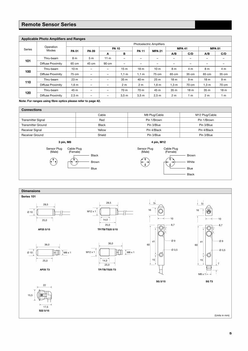
Dimensions
Series 101
28,5
25,0
Ø 10
AP25 5/15
36,0
25,0
Ø 10 M8 x 1
TP/TB/TS25 T3
28,5
14,0
25,0
M12 x 1
TP/TB/TS25 5/15
36,0
14,0
25,0
M12 x 1 M8 x 1
S22 5/15
22
17,5
15,5
AP25 T3
SG 5/15
10
8,7
Ø 9
5
16
41
15
60
Ø 3,5
SG T3
10
8,7
Ø 9
5
16
41
15
60
Ø 3,5
7
M8 x 1
Photoelectric Amplifiers
Series Operation
PA 01 PA 09PA 10
PA 11 MPA 21MPA 41 MPA 81
ModesA B A/B C/D A/B C/D
Thru-beam 8 m 5 m 11 m – – – – – – –101
Diffuse Proximity 65 cm 45 cm 90 cm – – – – – – –
Thru-beam 10 m – – 15 m 18 m 10 m 8 m 4 m 8 m 4 m100
Diffuse Proximity 75 cm – – 1,1 m 1,1 m 75 cm 65 cm 35 cm 65 cm 35 cm
Thru-beam 23 m – – 35 m 40 m 25 m 18 m 9 m 18 m 9 m110
Diffuse Proximity 1,6 m – – 2 m 2 m 1,6 m 1,3 m 70 cm 1,3 m 70 cm
Thru-beam 45 m – – 70 m 70 m 45 m 35 m 18 m 35 m 18 m120
Diffuse Proximity 2,5 m – – 3,5 m 3,5 m 2,5 m 2 m 1 m 2 m 1 m
Applicable Photo Amplifiers and Ranges
Connections
Cable M8 Plug/Cable M12 Plug/Cable
Transmitter Signal Red Pin 1/Brown Pin 1/Brown
Transmitter Ground Black Pin 3/Blue Pin 3/Blue
Receiver Signal Yellow Pin 4/Black Pin 4/Black
Receiver Ground Shield Pin 3/Blue Pin 3/Blue
Sensor Plug(Male)
Cable Plug(Female)
Sensor Plug(Male)
Cable Plug(Female)
12 4
3
1
324
41
43 3 1
Black
Brown
Blue
Brown
Black
White
Blue
Note: For ranges using fibre optics please refer to page 42.
3 pin, M8 4 pin, M12
(Units in mm)
Telco_2000_catalogue 5/1/1904 4:01 pm Page 5

6
Series 100/110
41,5
38,0
Ø 10
AP38 5/15
Series 120
55,0
45,0
M18 x 1
28,0
TB45 15
41,5
26,0
38,0
M12 x 1
TP/TB/TS38 5/15
49,0
26,0
38,0
M12 x 1 M8 x 1
TP/TB/TS38 T3
38,0
58,0
M12 x 1 M12 x 1
TB/TS58 J
Telco reserves the right to change specifications without notice.
(Units in mm)
(Units in mm)
Remote Sensor Series
AP38 T3
38,0
49,0
Ø 10 M8 x 1
Dimensions
Telco_2000_catalogue 5/1/1904 4:01 pm Page 6

Photoelectric Amplifier Series PA 01Amplifier Series
Description
� Operation mode and max sensing range:Thru beam: 0-45 mDiffuse proximity: 0-2,5 m
� 230 V ac, 115 V ac or 24 V ac/dc supplyvoltage
� Automatic and/or manual sensitivityadjustment
� Sensor LED-drive� Adjustable on/off time delay� 1 relay or 1 transistor output� STF� Switch selectable light or dark function� Switch selectable long or short range� Power, output and signal status indicators� Test input� 11-pole DIN socket connection
The PA 01 is to be used in conjunction with a set of remote transmitter
LT and receiver LR from the series 101, 100, 110 or 120. This amplifier
series offers a choice between automatic and/or manual sensitivity
adjustment with or without a 0-10 sec on/off time delay via integral
potentiometers located on the front panel of the amplifier. Output can be
selected from either a relay or an NPN/PNP transistor output. Light or
dark function and long or short range is switch selectable.
In automatic mode, set up is required. This is achieved by pressing the
teach-in button located on the front panel. This unique feature ensures
that the transmitting power level is adjusted according to the
application, thus achieving optimal hysteresis and excess gain. Once
set up, the system will automatically compensate for moderate
misalignment and contamination during operation. In manual mode,
the teach-in button allows for an overall manual system test by
temporarily disabling the transmitter. The sensor LED drive powers the
optional monitor LEDs available on the remote sensors – output (LT)
and power (LR).
The STF allows up to 3 identical systems to operate within a close
distance of each other without optical cross talk as each system
automatically maintains different transmitter frequencies.
Technical Data
Supply voltage 115 V ac, 230 V ac (+/– 15%)
12-30 V ac or 12-36 V dc
Current consumption Max. 2,5 VA
OutputRelay 1 open / 1 close, 230 V ac / 3 A, 120 V ac / 5 A
Transistor 100 mA / 36 V dc
Power on indicator Green LED
Output indicator Yellow LED
Signal status indicator Green LED
LR sensor failure indicator –
LT sensor failure indicator –
Sensor monitor LED driveThe green monitor LED on the receiver indicates ‘Power ON’
The yellow monitor LED on the transmitter indicates ‘PA 01 output activated’
Hysteresis Approx. 20 %
Operation frequency 12 Hz
Response time tON / tOFF 40 ms / 40 ms
Delay tON / tOFF PA 01 C 0 – 10 sec
Housing material Noryl
7
Environmental Data
Temperature, operation – 10 to +55 ºC
Temperature, storage – 40 to +80 ºC
Sealing class IP 40
Approvals a bc
Telco_2000_catalogue 5/1/1904 4:02 pm Page 7

Applicable Remote Sensors and Ranges
Series Thru Beam Diffuse Proximity
101 8 m 65 cm
100 10 m 75 cm
110 23 m 2 m
120 45 m 2,5 m
Wiring Diagrams
Dimensions
PA 01 Amplifier Series
8
2 10 1 3
NPN/PNP
LT LR
Black Red
Yellow
Shield
7 5 6 8 9 11
Test-input Invert
76
35 7413
RESET/TEST RESET/TEST
MANAUTO
76
35 7813
RESET/TEST
MANAUTO
TIME
76
35 7813
Relay
2 10 1 3 4
C NO
LT LR
Black Red
Yellow
ShieldNC
7 5 6 8 9 11
Test-input Invert
Available Types
12 – 30 V ac
Model ConnectionSupply Voltage
12 – 36 V dc 115 V ac 230 V ac
Output Order Reference
PA 01 A Relay PA 01 A 519 PA 01 A 511 PA 01 A 510
Automatic NPN and PNP PA 01 A 619 PA 01 A 611 PA 01 A 610
PA 01 B Relay PA 01 B 519 PA 01 B 511 PA 01 B 510
Automatic/Manual NPN and PNP PA 01 B 619 PA 01 B 611 PA 01 B 610
Relay PA 01 C 519 PA 01 C 511 PA 01 C 510
NPN and PNP PA 01 C 619 PA 01 C 611 PA 01 C 610
PA 01 CAutomatic/Manualon/off delay
11-pole DIN socket
PA 01 A PA 01 B PA 01 C
Telco reserves the right to change specifications without notice.
Note: Remote sensors and 11-pole DIN sockets to be ordered separately.
Relay output Transistor output
(Units in mm) (Units in mm) (Units in mm)
Telco_2000_catalogue 5/1/1904 4:02 pm Page 8

Photoelectric Amplifier Series PA 09Amplifier Series
Description
� Operation mode and max sensing range:Thru beam: 5 mDiffuse proximity: 0-45 cm
� 12 or 24 V dc supply voltage
� 1 relay output acc. to UNI 8612
� Power and output indicators
� Screw terminals connection
The PA 09 is to be used in conjunction with a set of remote transmitter LT
and receiver LR from the series 101.
This amplifier series is low cost, designed especially for the elevator and
door industries, offering a relay output, designed according to the
UNI 8612 standard whereby 2 relays are mounted in series.
Technical Data
Supply voltage 12 V dc or 24 V dc
Voltage tolerance @ 12 V dc –10 / +20 %
Voltage tolerance @ 24 V dc –15 / +20 %
Current consumption Max. 2 VA
Output relay 24 V dc / 2A
Power on indicator Green LED
Output indicator Yellow LED
Signal status indicator –
LR sensor failure indicator –
LT sensor failure indicator –
Sensor monitor LED drive –
Hysteresis Approx. 30 %
Operation frequency 10 Hz
Response time tON / tOFF 50 ms / 50 ms
Delay tON / tOFF –
Housing material Polystyrene
9
Environmental Data
Temperature, operation – 10 to +50 ºC
Temperature, storage – 40 to +80 ºC
Sealing class IP 40
Approvals a
Telco_2000_catalogue 5/1/1904 4:02 pm Page 9

Applicable Remote Sensors and Ranges
Series Thru Beam Diffuse Proximity
101 5 m 45 cm
Wiring Diagrams
Dimensions
1 2 3 4 5 6 7 8 9
C NC
NO
Pow
er –
Pow
er +
Bla
ck
Red
Shi
eld
Yello
w
Relay LT LR
53
52
83
Ø 5
5 5
10
Ø 5
22
PA 09 Amplifier Series
10
Available Types
Model ConnectionSupply Voltage 12 V dc 24 V dc
Output Order Reference
PA 09 B Screw terminals Relay PA 09 B 504 PA 09 B 503
PA 09 B
1 relay C
2 relay NC
3 relay NO
4 power –
5 power +
6
7
8
9
Black
Shield
Yellow
Red LT
LR
}}
LTLR
Relay output
Telco reserves the right to change specifications without notice.
Note: Remote sensors to be ordered separately.
(Units in mm)
Telco_2000_catalogue 5/1/1904 4:02 pm Page 10

Photoelectric Amplifier Series PA 10Amplifier Series
Description
� Operation mode and max sensing range:Thru beam: 0-70 mDiffuse proximity: 0-3,5 m
� 230 V ac, 115 V ac, 24 V ac or 24 V dc supply voltage
� Manual sensitivity adjustment
� 1 relay or 1 transistor output
� Switch selectable light or dark function
� Switch selectable long or short range
� Power and output indicators
� 11-pole DIN socket connection
The PA 10 A is to be used in conjunction with a remote transmitter LT and
receiver LR from series 101, whilst the PA 10 B is intended for use with
series 100, 110, and 120. This amplifier series offers manual sensitivity
adjustment via an integral potentiometer located on the front panel of the
amplifier. Output can be selected from either a relay or an NPN/PNP
transistor output. Light or dark function and long or short range are
switch selectable.
Technical Data
Supply voltage 24 V dc, 24 V ac, 115 V ac or 230 V ac
Voltage tolerance +/– 15 %
Current consumption Max. 3,2 VA
OutputRelay 1 open / 1 close, 250 V ac / 3 A, 120 V ac / 5 A
Transistor 40 mA / 30 V dc
Power on indicator Green LED
Output indicator Red LED
Signal level indicator –
LR sensor failure indicator –
LT sensor failure indicator –
Sensor monitor LED drive –
Hysteresis Approx. 40 %
Operation frequency 10 Hz
Response time tON / tOFF 40 ms / 40 ms
Delay tON / tOFF –
Housing material Noryl
11
Environmental Data
Temperature, operation – 10 to +50 ºC
Temperature, storage – 40 to +80 ºC
Sealing class IP 40
Approvals a b d
Telco_2000_catalogue 5/1/1904 4:02 pm Page 11

Applicable Remote Sensors and Ranges
Series Thru Beam Diffuse Proximity
101 (only PA 10 A) 11 m 90 cm
100 (only PA 10 B) 15 m 1,1 m
110 (only PA 10 B) 35 m 2 m
120 (only PA 10 B) 70 m 3,5 m
Wiring Diagrams
Dimensions
PA 10 Amplifier Series
12
Available Types
Model ConnectionSupply Voltage 24 V dc 24 V ac 115 V ac 230 V ac
Output Order Reference
PA 10 ARelay PA 10 A 513 PA 10 A 512 PA 10 A 511 PA 10 A 510
11-pole DIN socketNPN and PNP PA 10 A 613 PA 10 A 612 PA 10 A 611 PA 10 A 610
PA 10 BRelay PA 10 B 513 PA 10 B 512 PA 10 B 511 PA 10 B 510
NPN and PNP PA 10 B 613 PA 10 B 612 PA 10 B 611 PA 10 B 610
Relay
2 10 1 3 4
C NO NC
7 5 6
LT LR
Black Red Yellow Shield
8 2 10 9 11
NPN/PNP
7 5 6
LT LR
Black Red Yellow Shield
8
35
76
13 78
PA 10 A/B
Relay output Transistor output
Telco reserves the right to change specifications without notice.
Note: Remote sensors and 11-pole DIN sockets to be ordered separately.
(Units in mm)
Telco_2000_catalogue 5/1/1904 4:02 pm Page 12

Photoelectric Amplifier Series PA 11Amplifier Series
Description
� Operation mode and max sensing range:Thru beam: 0-70 mDiffuse proximity: 0-3,5 m
� 230 V ac, 115 V ac, 24 V ac or 24 V dc supply voltage
� Manual sensitivity adjustment
� Sensor LED-drive
� Automatic sensor test
� Adjustable on/off time delay
� 1 relay and/or 1 transistor output
� Switch selectable light or dark function
� Switch selectable long or short range
� Power, output and signal level indicators
� 11-pole DIN socket connection
The PA 11 is to be used in conjunction with a set of remote transmitter
LT and receiver LR from the series 100, 110 and 120.
This amplifier series offers manual sensitivity adjustment via integral
potentiometers located on the front panel of the amplifier output can be
selected from either a relay and NPN or NPN and PNP transistor outputs
with or without a 0-10 sec on/off time delay. Light or dark function and
long or short range is switch selectable.
The microprocessor controlled sensor test ensures that the system
will automatically detect and indicate a faulty transmitter or receiver –
cable break or electrical failure – during operation, through the relevant
LED located on the front panel. The sensor LED drive powers the
optional monitor LEDs available on the remote sensors – output (LT)
and power (LR).
Technical Data
Supply voltage 24 V dc, 24 V ac, 115 V ac or 230 V ac
Voltage tolerance +/– 15 %
Current consumption Max. 3,5 VA
OutputRelay 1 open / 1 close, 250 V ac / 3 A, 120 V ac / 5 A
Transistor 60 mA / 30 V dc
Power on indicator Green LED
Output indicator Yellow LED
Signal level indicator Green LED
LR sensor failure indicator Red LED
LT sensor failure indicator Red LED
Sensor monitor LED driveThe green monitor LED on the receiver indicates ‘Power ON’
The yellow monitor LED on the transmitter indicates ‘PA 11 output activated’
Hysteresis Approx. 45 %
Operation frequency 20 Hz
Response time tON / tOFF 35 ms / 35 ms
Delay tON / tOFF PA 11 A Adjustable 0 – 10 sec
Housing material Noryl
13
Environmental Data
Temperature, operation –10 to +50 ºC
Temperature, storage –40 to +80 ºC
Sealing class IP 40
Approvals a bc
Telco_2000_catalogue 5/1/1904 4:02 pm Page 13

Applicable Remote Sensors and Ranges
Series Thru Beam Diffuse Proximity
100 18 m 1,1 m
110 40 m 2 m
120 70 m 3,5 m
Wiring Diagrams
Dimensions
PA 11 Amplifier Series
14
Available Types
Model ConnectionSupply Voltage 24 V dc 24 V ac 115 V ac 230 V ac
Output Order Reference
PA 11 A Relay and NPN PA 11 A 303T PA 11 A 302T PA 11 A 301T PA 11 A 300T
On/Off delay11-pole DIN socket
NPN and PNP PA 11 A 403T PA 11 A 402T PA 11 A 401T PA 11 A 400T
PA 11 BRelay and NPN PA 11 B 303T PA 11 B 302T PA 11 B 301T PA 11 B 300T
NPN and PNP PA 11 B 403T PA 11 B 402T PA 11 B 401T PA 11 B 400T
Relay
2 10 1 3 4 9
CNPN
NO
LT LR
Black Red YellowShield
Load Supply
NC
7 5 6 8
SupplyVoltage
2
Load SupplyLT LR
Black Red YellowShield
10
PNPNPN
9 1 3 7 5 6 8
SupplyVoltage
35
76
13 78
LTLR
35
76
13 78
LT
LR
Relay output Transistor output
PA 11 A PA 11 B
Telco reserves the right to change specifications without notice.
Note: Remote sensors and 11-pole DIN sockets to be ordered separately.
(Units in mm)(Units in mm)
Telco_2000_catalogue 5/1/1904 4:02 pm Page 14

Photoelectric Amplifier Series MPA 21Multiplexed Amplifier Series
Description
� Operation mode and max sensing range:Thru beam: 0-45 mDiffuse proximity: 0-2,5 m
� 230 V ac, 115 V ac, 24 V ac or 24 V dc supply voltage
� Manual sensitivity adjustment
� Adjustable on/off time delay
� 2 relays or 2 transistor outputs
� Power, output and signal level indicators
� Switch selectable light or dark function
� Switch selectable long or short range
� 11-pole DIN socket connection
The MPA 21 is to be used in conjunction with 2 sets of remote
transmitters LT and receivers LR, from the series 100, 110 and 120.
The 2 channels operate independently of each other with their own set of
remote transmitter and receiver. The multiplexing function ensures that
optical cross talk between channels is prevented.
The series offers a choice between 2 individual relays or 2 individual
NPN/PNP transistor outputs, with or without an adjustable 0-3 sec on/off
time delay.
This amplifier series offers manual sensitivity adjustment for each
individual channel via integral potentiometers located on the front panel
of the amplifier. Light or dark function and long or short range is switch
selectable for each individual channel.
Technical Data
Supply voltage 24 V dc, 24 V ac, 115 V ac or 230 V ac
Voltage tolerance +/– 15 %
Current consumption Max. 3 VA
Output Relay 1 open / 1 close, 250 V ac / 3 A, 120 V ac / 5 A
Transistor 40 mA / 30 V dc
Power on indicator Green LED
Output indicator Red LED
Signal level indicator Green LED
LR sensor failure indicator –
LT sensor failure indicator –
Sensor monitor LED drive –
Hysteresis Approx. 35 %
Operation frequencyMPA 21 A 9 Hz
MPA 21 B 11 Hz
Response time tON / tOFF
MPA 21 A 55 ms / 55 ms
MPA 21 B 45 ms / 45 ms
Delay tON / tOFF MPA 21 A 0 – 3 sec
Housing material Noryl
15
Environmental Data
Temperature, operation – 10 to +50 ºC
Temperature, storage – 40 to +80 ºC
Sealing class IP 40
Approvals a b d
Telco_2000_catalogue 5/1/1904 4:02 pm Page 15

Applicable Remote Sensors and Ranges
Series Thru Beam Diffuse Proximity
100 10 m 75 cm
110 25 m 1,6 m
120 45 m 2,5 m
Wiring Diagrams
Dimensions
MPA 21 Multiplexed Amplifier Series
16
Available Types
Model ConnectionSupply Voltage 24 V dc 24 V ac 115 V ac 230 V ac
Output Order Reference
MPA 21 A 2 individual relays MPA 21 A 503 MPA 21 A 502 MPA 21 A 501 MPA 21 A 500
On/Off delay11-pole DIN socket
2 individual NPN/PNP MPA 21 A 603 MPA 21 A 602 MPA 21 A 601 MPA 21 A 600
MPA 21 B2 individual relays MPA 21 B 503 MPA 21 B 502 MPA 21 B 501 MPA 21 B 500
2 individual NPN/PNP MPA 21 B 603 MPA 21 B 602 MPA 21 B 601 MPA 21 B 600
Relay
2 10 1 3 4
Ch1 Ch2
5 7 11
LR
Black
9 8 6
LT LRRed
Red Yellow Shield Yellow
Ch1
Ch2
LT
NPN/PNP
2 10 3 4 1
Ch1 Ch2
5 7 11
LT LR
Black
9 8 6
LT LRRed
Red Yellow Shield Yellow
Ch1
Ch2
35
76
13 78 35
76
13 78
MPA 21 A MPA 21 B
Relay output Transistor output
Telco reserves the right to change specifications without notice.
Note: Remote sensors and 11-pole DIN sockets to be ordered separately.
(Units in mm)(Units in mm)
Telco_2000_catalogue 5/1/1904 4:02 pm Page 16
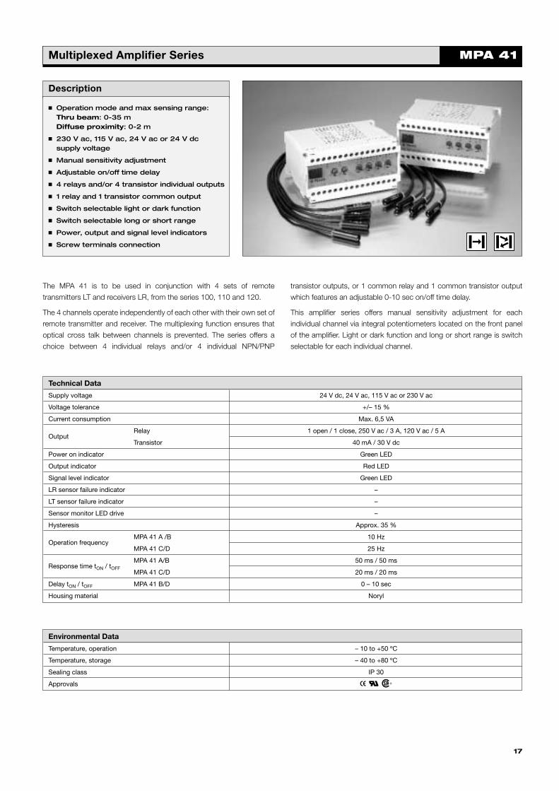
Photoelectric Amplifier Series MPA 41Multiplexed Amplifier Series
Description
� Operation mode and max sensing range:Thru beam: 0-35 mDiffuse proximity: 0-2 m
� 230 V ac, 115 V ac, 24 V ac or 24 V dcsupply voltage
� Manual sensitivity adjustment
� Adjustable on/off time delay
� 4 relays and/or 4 transistor individual outputs
� 1 relay and 1 transistor common output
� Switch selectable light or dark function
� Switch selectable long or short range
� Power, output and signal level indicators
� Screw terminals connection
The MPA 41 is to be used in conjunction with 4 sets of remote
transmitters LT and receivers LR, from the series 100, 110 and 120.
The 4 channels operate independently of each other with their own set of
remote transmitter and receiver. The multiplexing function ensures that
optical cross talk between channels is prevented. The series offers a
choice between 4 individual relays and/or 4 individual NPN/PNP
transistor outputs, or 1 common relay and 1 common transistor output
which features an adjustable 0-10 sec on/off time delay.
This amplifier series offers manual sensitivity adjustment for each
individual channel via integral potentiometers located on the front panel
of the amplifier. Light or dark function and long or short range is switch
selectable for each individual channel.
Technical Data
Supply voltage 24 V dc, 24 V ac, 115 V ac or 230 V ac
Voltage tolerance +/– 15 %
Current consumption Max. 6,5 VA
Output Relay 1 open / 1 close, 250 V ac / 3 A, 120 V ac / 5 A
Transistor 40 mA / 30 V dc
Power on indicator Green LED
Output indicator Red LED
Signal level indicator Green LED
LR sensor failure indicator –
LT sensor failure indicator –
Sensor monitor LED drive –
Hysteresis Approx. 35 %
Operation frequencyMPA 41 A /B 10 Hz
MPA 41 C/D 25 Hz
Response time tON / tOFF
MPA 41 A/B 50 ms / 50 ms
MPA 41 C/D 20 ms / 20 ms
Delay tON / tOFF MPA 41 B/D 0 – 10 sec
Housing material Noryl
17
Environmental Data
Temperature, operation – 10 to +50 ºC
Temperature, storage – 40 to +80 ºC
Sealing class IP 30
Approvals a b d
Telco_2000_catalogue 5/1/1904 4:02 pm Page 17
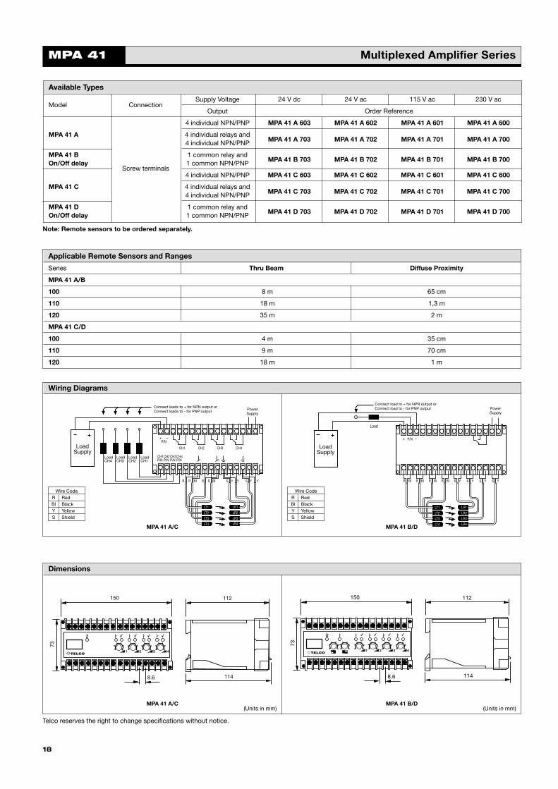
Applicable Remote Sensors and Ranges
Series Thru Beam Diffuse Proximity
MPA 41 A/B
100 8 m 65 cm
110 18 m 1,3 m
120 35 m 2 m
MPA 41 C/D
100 4 m 35 cm
110 9 m 70 cm
120 18 m 1 m
Wiring Diagrams
Dimensions
MPA 41 Multiplexed Amplifier Series
18
Available Types
Model ConnectionSupply Voltage 24 V dc 24 V ac 115 V ac 230 V ac
Output Order Reference
4 individual NPN/PNP MPA 41 A 603 MPA 41 A 602 MPA 41 A 601 MPA 41 A 600
MPA 41 A 4 individual relays andMPA 41 A 703 MPA 41 A 702 MPA 41 A 701 MPA 41 A 7004 individual NPN/PNP
MPA 41 B 1 common relay andMPA 41 B 703 MPA 41 B 702 MPA 41 B 701 MPA 41 B 700On/Off delay
Screw terminals1 common NPN/PNP
4 individual NPN/PNP MPA 41 C 603 MPA 41 C 602 MPA 41 C 601 MPA 41 C 600
MPA 41 C 4 individual relays andMPA 41 C 703 MPA 41 C 702 MPA 41 C 701 MPA 41 C 7004 individual NPN/PNP
MPA 41 D 1 common relay andMPA 41 D 703 MPA 41 D 702 MPA 41 D 701 MPA 41 D 700On/Off delay 1 common NPN/PNP
73
150
8.6
112
114
4321
73
150
8.6
112
114
4321
LoadCH4
LoadCH3
LoadCH2
PowerSupply
LoadCH1
CH1P/N
CH2P/N
CH3P/N
CH4P/N
R R BI R R BI S Y Y S Y Y
CH1 CH2 CH3 CH4
+ –P/N
Connect loads to + for NPN output orConnect loads to - for PNP output
LT1
LT2
LT3
LT4
LR1
LR2
LR3LR4
LoadSupply
PowerSupply
R BI S Y
+ P/N -
Connect load to + for NPN output orConnect load to - for PNP output
LoadSupply
LT1
LT2
LT3
LT4
LR1
LR2
LR3LR4
R BI R BI R BI S Y S Y S Y
Load
Wire CodeR RedBl BlackY YellowS Shield
Wire CodeR RedBl BlackY YellowS Shield
MPA 41 A/C MPA 41 B/D
MPA 41 A/C MPA 41 B/D
Telco reserves the right to change specifications without notice.
Note: Remote sensors to be ordered separately.
(Units in mm)(Units in mm)
Telco_2000_catalogue 5/1/1904 4:02 pm Page 18
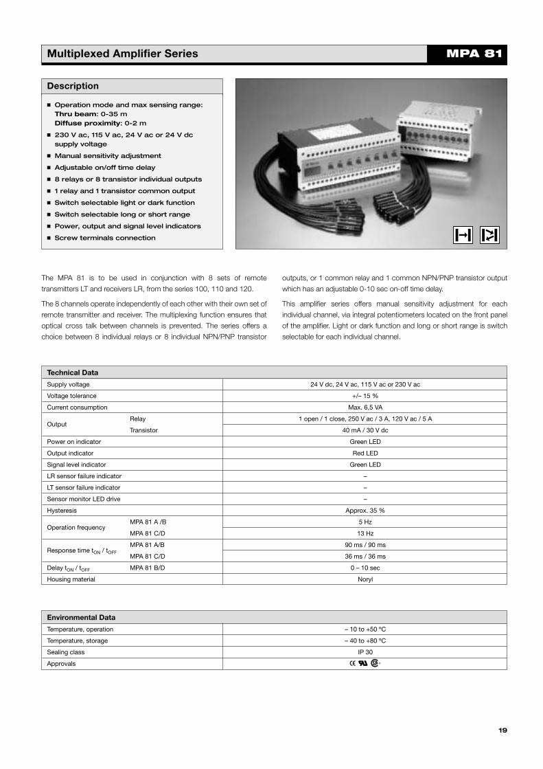
Photoelectric Amplifier Series MPA 81Multiplexed Amplifier Series
Description
� Operation mode and max sensing range:Thru beam: 0-35 mDiffuse proximity: 0-2 m
� 230 V ac, 115 V ac, 24 V ac or 24 V dcsupply voltage
� Manual sensitivity adjustment
� Adjustable on/off time delay
� 8 relays or 8 transistor individual outputs
� 1 relay and 1 transistor common output
� Switch selectable light or dark function
� Switch selectable long or short range
� Power, output and signal level indicators
� Screw terminals connection
The MPA 81 is to be used in conjunction with 8 sets of remote
transmitters LT and receivers LR, from the series 100, 110 and 120.
The 8 channels operate independently of each other with their own set of
remote transmitter and receiver. The multiplexing function ensures that
optical cross talk between channels is prevented. The series offers a
choice between 8 individual relays or 8 individual NPN/PNP transistor
outputs, or 1 common relay and 1 common NPN/PNP transistor output
which has an adjustable 0-10 sec on-off time delay.
This amplifier series offers manual sensitivity adjustment for each
individual channel, via integral potentiometers located on the front panel
of the amplifier. Light or dark function and long or short range is switch
selectable for each individual channel.
Technical Data
Supply voltage 24 V dc, 24 V ac, 115 V ac or 230 V ac
Voltage tolerance +/– 15 %
Current consumption Max. 6,5 VA
OutputRelay 1 open / 1 close, 250 V ac / 3 A, 120 V ac / 5 A
Transistor 40 mA / 30 V dc
Power on indicator Green LED
Output indicator Red LED
Signal level indicator Green LED
LR sensor failure indicator –
LT sensor failure indicator –
Sensor monitor LED drive –
Hysteresis Approx. 35 %
Operation frequencyMPA 81 A /B 5 Hz
MPA 81 C/D 13 Hz
Response time tON / tOFF
MPA 81 A/B 90 ms / 90 ms
MPA 81 C/D 36 ms / 36 ms
Delay tON / tOFF MPA 81 B/D 0 – 10 sec
Housing material Noryl
19
Environmental Data
Temperature, operation – 10 to +50 ºC
Temperature, storage – 40 to +80 ºC
Sealing class IP 30
Approvals a b d
Telco_2000_catalogue 5/1/1904 4:02 pm Page 19
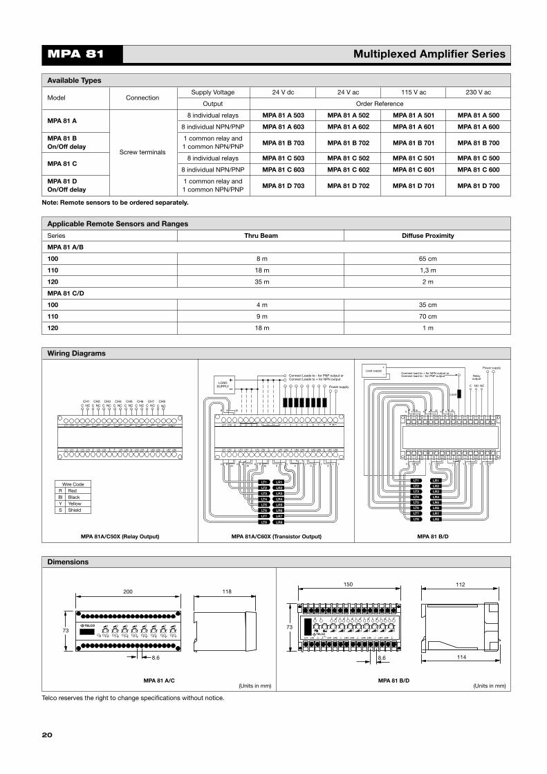
Applicable Remote Sensors and Ranges
Series Thru Beam Diffuse Proximity
MPA 81 A/B
100 8 m 65 cm
110 18 m 1,3 m
120 35 m 2 m
MPA 81 C/D
100 4 m 35 cm
110 9 m 70 cm
120 18 m 1 m
Wiring Diagrams
Dimensions
MPA 81 Multiplexed Amplifier Series
20
Available Types
Model ConnectionSupply Voltage 24 V dc 24 V ac 115 V ac 230 V ac
Output Order Reference
MPA 81 A8 individual relays MPA 81 A 503 MPA 81 A 502 MPA 81 A 501 MPA 81 A 500
8 individual NPN/PNP MPA 81 A 603 MPA 81 A 602 MPA 81 A 601 MPA 81 A 600
MPA 81 B 1 common relay andMPA 81 B 703 MPA 81 B 702 MPA 81 B 701 MPA 81 B 700On/Off delay
Screw terminals1 common NPN/PNP
MPA 81 C8 individual relays MPA 81 C 503 MPA 81 C 502 MPA 81 C 501 MPA 81 C 500
8 individual NPN/PNP MPA 81 C 603 MPA 81 C 602 MPA 81 C 601 MPA 81 C 600
MPA 81 D 1 common relay andMPA 81 D 703 MPA 81 D 702 MPA 81 D 701 MPA 81 D 700On/Off delay 1 common NPN/PNP
LT7 LT8
LT1 LT2 LT3 LT4 LT5 LT6 LR1 LR2 LR3 LR4 LR5 LR6 LR7 LR8
1 2 3 4 5 6 7 8
CH1C NC
CH2C NC
CH3C NC
CH4C NC
CH5C NC
CH6C NC
CH7C NC
CH8C NC
LT7 LT8
LT1 LT2 LT3 LT4 LT5 LT6 LR1 LR2 LR3 LR4 LR5 LR6 LR7 LR8
LOADSUPPLY
R R BI
R RBI
R RBI
R RBI S
Y YS
Y YS
Y YS
Y Y
Connect Loads to - for PNP output orConnect Loads to + for NPN output
Power supply
1 2 3 4 5 6 7 8
LR1
LR2
LR3
LR4
LR5
LR6
LR7
LR8LT8
LT7
LT6
LT5
LT4
LT3
LT2
LT1
R RBI
R RBI
R RBI
R R BI Y Y S Y Y Y Y S Y Y S
Load
C NO NC
Relayoutput
Power supply
Connect load to + for NPN output orConnect load to - for PNP output
S
Load supply+
-
LT1
LT7
LT8
LT2
LT3
LT4
LT5
LT6 LR6
LR4
LR2
LR1
LR5
LR7
LR8
LR3
200
73
8.6
118
1 2 3 4 5 6 7 8
150
8.6
112
114
73
Wire CodeR RedBl BlackY YellowS Shield
MPA 81 A/C MPA 81 B/D
MPA 81A/C50X (Relay Output) MPA 81A/C60X (Transistor Output) MPA 81 B/D
Telco reserves the right to change specifications without notice.
Note: Remote sensors to be ordered separately.
(Units in mm)(Units in mm)
Telco_2000_catalogue 5/1/1904 4:02 pm Page 20

SM 3000Spacemaster Series
Description
� Operation mode and max sensing range:Thru beam: 0-6 m
� Cable or plug connection
� Sensitivity adjustment via control input
� Wide variety of housings
� Output indicator
� High tolerance to hostile environments
� 10 – 30 V dc supply voltage
� 3 wire, NPN or PNP transistor output
The 3000 series consists of a low cost self-contained transmitter SMT,
and a receiver SMR, which are to be used in thru beam mode. The
complete series is available in a wide range of housings with either cable
or plug connection.
The SMR is supplied with a 10-30 V dc supply voltage with a 3 wire, NPN
or PNP transistor output with a choice between light or dark function.
The control input in the SMT may be used for either disabling or enabling
the transmitting power temporarily for test purpose, multiplexing
applications or as a gradual regulation of the transmitting power level.
Both the transmitter and receiver are protected against reverse polarity.
Technical Data
SMT SMR
Supply voltage 10 – 30 V dc
Voltage ripple 20%
Reverse polarity protected Yes
Short circuit protected –
Current consumption 30 mA @ 30 V dc 23 mA @ 30 V dc
Maximum output load – 100 mA
Maximum residual voltage – 2,1 V
Maximum operation frequency – 100 Hz
Response time tON / tOFF – 7 ms / 4 ms
Power on indicator – –
Output indicator – Red LED
Hysteresis – Approx. 30 %
Transmitter diode Ga Al As (880 nm) –
Opening angle – +/– 9°
Emission angle +/– 12° –
Environmental Data
Vibration 10 – 55 Hz, 0,5 mm
Shock 30 g
Light immunity, @ 20° incidence >20 000 lux
Temperature, operation – 20 to +50 ºC
Temperature, storage – 40 to +80 ºC
Sealing class IP 67
Approvals a
21
Telco_2000_catalogue 5/1/1904 4:02 pm Page 21
Tran
smit
ter
SM 3000 Spacemaster SeriesR
ecei
ver
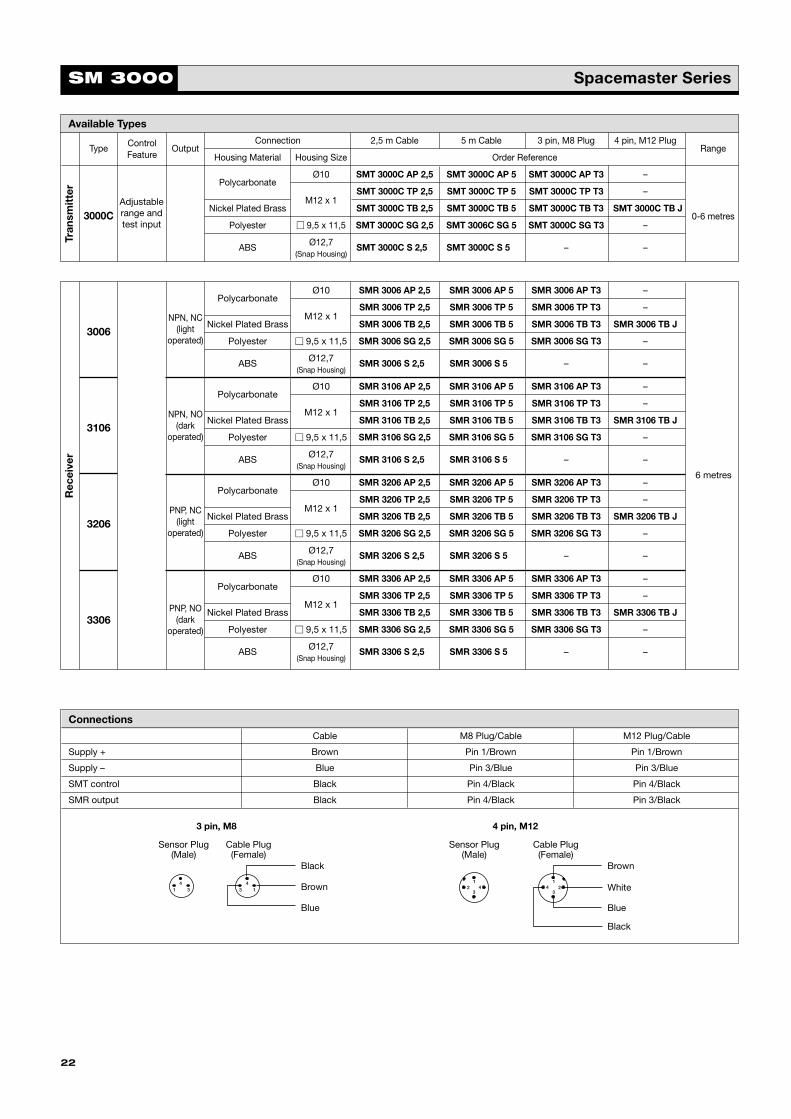
PolycarbonateØ10 SMR 3006 AP 2,5 SMR 3006 AP 5 SMR 3006 AP T3 –
SMR 3006 TP 2,5 SMR 3006 TP 5 SMR 3006 TP T3 –
3006Nickel Plated Brass
M12 x 1SMR 3006 TB 2,5 SMR 3006 TB 5 SMR 3006 TB T3 SMR 3006 TB J
Polyester � 9,5 x 11,5 SMR 3006 SG 2,5 SMR 3006 SG 5 SMR 3006 SG T3 –
ABS Ø12,7 SMR 3006 S 2,5S SMR 3006 S 5S – –(Snap Housing)
PolycarbonateØ10 SMR 3106 AP 2,5 SMR 3106 AP 5 SMR 3106 AP T3 –
SMR 3106 TP 2,5 SMR 3106 TP 5 SMR 3106 TP T3 –
3106Nickel Plated Brass
M12 x 1SMR 3106 TB 2,5 SMR 3106 TB 5 SMR 3106 TB T3 SMR 3106 TB J
Polyester � 9,5 x 11,5 SMR 3106 SG 2,5 SMR 3106 SG 5 SMR 3106 SG T3 –
ABS Ø12,7 SMR 3106 S 2,5S SMR 3106 S 5S – –(Snap Housing)
PolycarbonateØ10 SMR 3206 AP 2,5 SMR 3206 AP 5 SMR 3206 AP T3 –
SMR 3206 TP 2,5 SMR 3206 TP 5 SMR 3206 TP T3 –
3206Nickel Plated Brass
M12 x 1SMR 3206 TB 2,5 SMR 3206 TB 5 SMR 3206 TB T3 SMR 3206 TB J
Polyester � 9,5 x 11,5 SMR 3206 SG 2,5 SMR 3206 SG 5 SMR 3206 SG T3 –
ABS Ø12,7 SMR 3206 S 2,5S SMR 3206 S 5S – –(Snap Housing)
PolycarbonateØ10 SMR 3306 AP 2,5 SMR 3306 AP 5 SMR 3306 AP T3 –
SMR 3306 TP 2,5 SMR 3306 TP 5 SMR 3306 TP T3 –
3306Nickel Plated Brass
M12 x 1SMR 3306 TB 2,5 SMR 3306 TB 5 SMR 3306 TB T3 SMR 3306 TB J
Polyester � 9,5 x 11,5 SMR 3306 SG 2,5 SMR 3306 SG 5 SMR 3306 SG T3 –
ABS Ø12,7 SMR 3306 S 2,5S SMR 3306 S 5S – –(Snap Housing)
NPN, NC(light
operated)
NPN, NO(dark
operated)
PNP, NO(dark
operated)
PNP, NC(light
operated)
6 metres
Type Control OutputConnection 2,5 m Cable 5 m Cable 3 pin, M8 Plug 4 pin, M12 Plug
RangeFeature Housing Material Housing Size Order Reference
PolycarbonateØ10 SMT 3000C AP 2,5 SMT 3000C AP 5 SMT 3000C AP T3 –
SMT 3000C TP 2,5 SMT 3000C TP 5 SMT 3000C TP T3 –
3000CNickel Plated Brass
M12 x 1SMT 3000C TB 2,5 SMT 3000C TB 5 SMT 3000C TB T3 SMT 3000C TB J
0-6 metresPolyester � 9,5 x 11,5 SMT 3000C SG 2,5 SMT 3006C SG 5 SMT 3000C SG T3 –
ABS Ø12,7 SMT 3000C S 2,5S SMT 3000C S 5 – –(Snap Housing)
Available Types
Adjustablerange andtest input
22
Connections
Cable M8 Plug/Cable M12 Plug/Cable
Supply + Brown Pin 1/Brown Pin 1/Brown
Supply – Blue Pin 3/Blue Pin 3/Blue
SMT control Black Pin 4/Black Pin 4/Black
SMR output Black Pin 4/Black Pin 3/Black
Sensor Plug(Male)
Cable Plug(Female)
Sensor Plug(Male)
Cable Plug(Female)
12 4
3
1
324
41
43 3 1
Black
Brown
Blue
Brown
Black
White
Blue
3 pin, M8 4 pin, M12
Telco_2000_catalogue 5/1/1904 4:02 pm Page 22
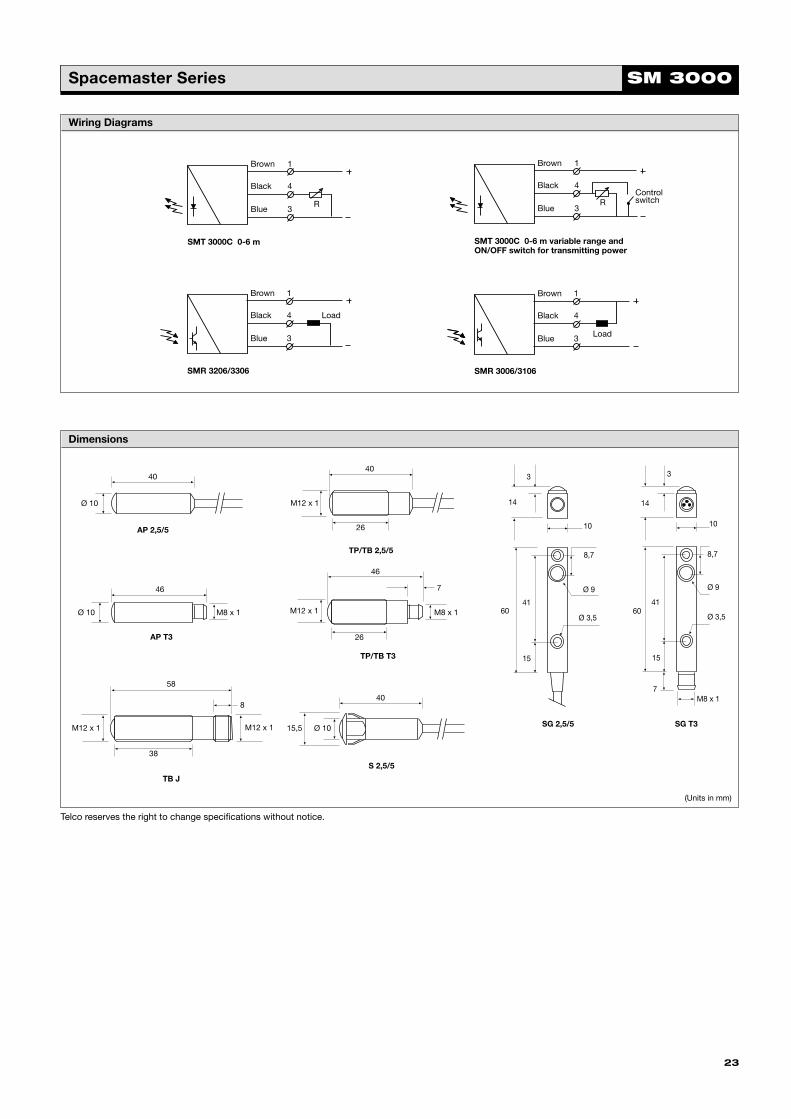
Wiring Diagrams
Dimensions
SM 3000Spacemaster Series
23
40
Ø 10
46
Ø 10 M8 x 1
46
26
M12 x 1
7
M8 x 1
40
26
M12 x 1
8,7
Ø 9
41
15
60Ø 3,5
10
3
14
10
8,7
Ø 9
3
14
41
15
60Ø 3,5
7M8 x 1
58
38
M12 x 1
8
M12 x 1
Brown
Black
Blue
SMT 3000C 0-6 m
R
1
4
3
Brown
Black
Blue
SMT 3000C 0-6 m variable range andON/OFF switch for transmitting power
ControlswitchR
1
4
3
Brown
Black
Blue
Load
SMR 3206/3306
1
4
3
Brown
Black
Blue Load
SMR 3006/3106
1
4
3
Telco reserves the right to change specifications without notice.
AP 2,5/5
AP T3
S 2,5/5
TB J
TP/TB 2,5/5
SG T3SG 2,5/5
(Units in mm)
40
Ø 1015,5
TP/TB T3
Telco_2000_catalogue 5/1/1904 4:02 pm Page 23

24
Telco_2000_catalogue 5/1/1904 4:02 pm Page 24

Description
� Operation mode and max sensing range:Thru beam: 0-6 m
� Cable or plug connection
� Sensitivity adjustment via control input
� Wide variety of housings
� Power and output indicators
� High tolerance to hostile environments
� 10 – 30 V dc supply voltage
� 3 wire, NPN or PNP output or4 wire, NPN/PNP opto isolated output
� 5 or 0,5 ms response time
� Low current consumption
The 6000 series consists of a self-contained transmitter SMT, and a
receiver SMR, which are to be used in thru beam mode. The complete
series is available in a wide range of housings with either plug or cable
connection.
The SMR is supplied with a 10-32 V dc supply voltage with either a
3 wire, NPN or PNP or as a 4 wire, NPN/PNP opto-isolated transistor
output with a choice between light or dark function. The SMR is available
with either a 0.5 ms response time with a 2 metre range, or with a 5 ms
response time with a 6 metre range. The control input in the SMT may be
used for either disabling or enabling the transmitting power temporarily
for test purpose, multiplexing applications or as a gradual regulation of
the transmitting power level.
Both the transmitter and receiver are protected against reverse polarity of
power supplies, control input and output signals. The output is also
protected against short circuit and inductive loads.
Technical Data
SMT SMR
– 6x00 6x01
Supply voltage 10 – 30 V dc
Voltage ripple 15 %
Reverse polarity protected Yes
Short circuit protected Yes
Current consumption 10 mA @ 32 V dc 10 mA @ 32 V dc
Maximum output load – 100 mA
Maximum residual voltage – 2,5 V
Maximum operation frequency – 100 Hz 1000 Hz
Response time tON / tOFF – 5 ms / 5 ms 0,5 ms / 0,5 ms
Power on indicator Green LED –
Output indicator – Yellow LED
Hysteresis – Approx. 30%
Transmitter diode Ga Al As (880 nm) –
Opening angle – +/– 6°
Emission angle +/– 10° –
Environmental Data
Vibration 10 – 55 Hz, 0,5 mm
Shock 30 g
Light immunity, @ 5° incidence >50 000 lux
Temperature, operation – 20 to +60 ºC
Temperature, storage – 40 to +80 ºC
Sealing class IP 67
Approvals a
25
SM 6000Spacemaster Series
Telco_2000_catalogue 5/1/1904 4:02 pm Page 25

Rec
eive
rTr
ansm
itte
r
Type Control OutputConnection 5 m Cable 3 pin, M8 Plug 4 pin, M8 Plug 4 pin, M12 Plug
RangeFeature Housing Material Housing Size Order Reference
PolycarbonateØ10 SMT 6000 AP 5 SMT 6000 AP T3 – –
M12 x 1 SMT 6000 TP 5 SMT 6000 TP T3 – –
6000Stainless Steel
Ø10 SMT 6000 AS 5 SMT 6000 AS T3 SMT 6000 AS T4 –
M12 x 1 SMT 6000 TS 5 SMT 6000 TS T3 SMT 6000 TS T4 SMT 6000 TS J
Polyester � 9,5 x 11,5 SMT 6000 SG 5 SMT 6000 SG T3 – –
Available Types
Adjustablerange andtest input
1 – 6 metres
PolycarbonateØ10 SMR 6000 AP 5 SMR 6000 AP T3 – –
M12 x 1 SMR 6000 TP 5 SMR 6000 TP T3 – –
6000Stainless Steel
Ø10 SMR 6000 AS 5 SMR 6000 AS T3 – –
M12 x 1 SMR 6000 TS 5 SMR 6000 TS T3 – SMR 6000 TS J
Polyester � 9,5 x 11,5 SMR 6000 SG 5 SMR 6000 SG T3 – –
PolycarbonateØ10 SMR 6100 AP 5 SMR 6100 AP T3 – –
M12 x 1 SMR 6100 TP 5 SMR 6100 TP T3 – –
6100Stainless Steel
Ø10 SMR 6100 AS 5 SMR 6100 AS T3 – –
M12 x 1 SMR 6100 TS 5 SMR 6100 TS T3 – SMR 6100 TS J
Polyester � 9,5 x 11,5 SMR 6100 SG 5 SMR 6100 SG T3 – –
PolycarbonateØ10 SMR 6200 AP 5 SMR 6200 AP T3 – –
M12 x 1 SMR 6200 TP 5 SMR 6200 TP T3 – –
6200Stainless Steel
Ø10 SMR 6200 AS 5 SMR 6200 AS T3 – –
M12 x 1 SMR 6200 TS 5 SMR 6200 TS T3 – SMR 6200 TS J
Polyester � 9,5 x 11,5 SMR 6200 SG 5 SMR 6200 SG T3 – –
PolycarbonateØ10 SMR 6300 AP 5 SMR 6300 AP T3 – –
M12 x 1 SMR 6300 TP 5 SMR 6300 TP T3 – –
6300Stainless Steel
Ø10 SMR 6300 AS 5 SMR 6300 AS T3 – –
M12 x 1 SMR 6300 TS 5 SMR 6300 TS T3 – SMR 6300 TS J
Polyester � 9,5 x 11,5 SMR 6300 SG 5 SMR 6300 SG T3 – –
6400Ø10 – – SMR 6400 AS T4 –
Stainless SteelM12 x 1 – – SMR 6400 TS T4 SMR 6400 TS J
6500Ø10 – – SMR 6500 AS T4 –
M12 x 1 – – SMR 6500 TS T4 SMR 6500 TS J
NPN, NC(light
operated)
NPN, NO(dark
operated)
PNP, NC(light
operated)
PNP, NO(dark
operated)
NPN/PNP,NO
(darkoperated)
NPN/PNP,NC
(lightoperated)
6 metres
SM 6000 Spacemaster Series
26
Telco_2000_catalogue 5/1/1904 4:02 pm Page 26
27
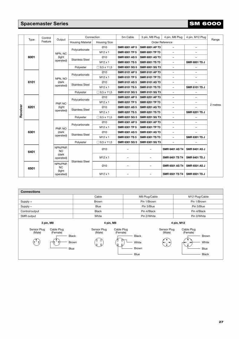
SM 6000Spacemaster SeriesR
ecei
ver
Type Control OutputConnection 5m Cable 3 pin, M8 Plug 4 pin, M8 Plug 4 pin, M12 Plug
RangeFeature Housing Material Housing Size Order Reference
PolycarbonateØ10 SMR 6001 AP 5 SMR 6001 AP T3 – –
M12 x 1 SMR 6001 TP 5 SMR 6001 TP T3 – –
6001Stainless Steel
Ø10 SMR 6001 AS 5 SMR 6001 AS T3 – –
M12 x 1 SMR 6001 TS 5 SMR 6001 TS T3 – SMR 6001 TS J
Polyester � 9,5 x 11,5 SMR 6001 SG 5 SMR 6001 SG T3 – –
PolycarbonateØ10 SMR 6101 AP 5 SMR 6101 AP T3 – –
M12 x 1 SMR 6101 TP 5 SMR 6101 TP T3 – –
6101Stainless Steel
Ø10 SMR 6101 AS 5 SMR 6101 AS T3 – –
M12 x 1 SMR 6101 TS 5 SMR 6101 TS T3 – SMR 6101 TS J
Polyester � 9,5 x 11,5 SMR 6101 SG 5 SMR 6101 SG T3 – –
PolycarbonateØ10 SMR 6201 AP 5 SMR 6201 AP T3 – –
M12 x 1 SMR 6201 TP 5 SMR 6201 TP T3 – –
6201Stainless Steel
Ø10 SMR 6201 AS 5 SMR 6201 AS T3 – –2 metres
M12 x 1 SMR 6201 TS 5 SMR 6201 TS T3 – SMR 6201 TS J
Polyester � 9,5 x 11,5 SMR 6201 SG 5 SMR 6201 SG T3 – –
PolycarbonateØ10 SMR 6301 AP 5 SMR 6301 AP T3 – –
M12 x 1 SMR 6301 TP 5 SMR 6301 TP T3 – –
6301Stainless Steel
Ø10 SMR 6301 AS 5 SMR 6301 AS T3 – –
M12 x 1 SMR 6301 TS 5 SMR 6301 TS T3 – SMR 6301 TS J
Polyester � 9,5 x 11,5 SMR 6301 SG 5 SMR 6301 SG T3 – –
6401Ø10 – – SMR 6401 AS T4 SMR 6401 AS J
Stainless SteelM12 x 1 – – SMR 6401 TS T4 SMR 6401 TS J
6501Ø10 – – SMR 6501 AS T4 SMR 6501 AS J
M12 x 1 – – SMR 6501 TS T4 SMR 6501 TS J
NPN, NC(light
operated)
NPN, NO(dark
operated)
PNP, NC(light
operated)
PNP, NO(dark
operated)
NPN/PNP,NO
(darkoperated)
NPN/PNP,NC
(lightoperated)
Connections
Cable M8 Plug/Cable M12 Plug/Cable
Supply + Brown Pin 1/Brown Pin 1/Brown
Supply – Blue Pin 3/Blue Pin 3/Blue
Control/output Black Pin 4/Black Pin 4/Black
SMR output White Pin 2/White Pin 2/White
4
3
2
1
Sensor Plug(Male)
Cable Plug(Female)
Sensor Plug(Male)
Cable Plug(Female)
2
1
4
3
41
43 3 1
Black
Brown
Blue
Black
Blue
Sensor Plug(Male)
Cable Plug(Female)
12 4
3
1
324
Brown
Black
White
Brown
White
Blue
3 pin, M8 4 pin, M8 4 pin, M12
Telco_2000_catalogue 5/1/1904 4:02 pm Page 27
28
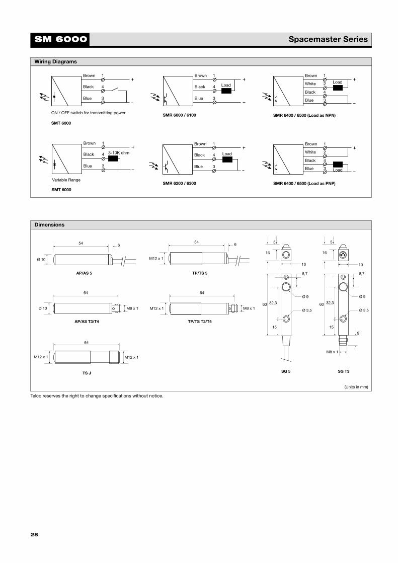
Wiring Diagrams
Dimensions
60
8,7
16
Ø 9
Ø 3,5
5
15
32,3
10
64
M12 x 1M12 x 1
654
M12 x 1
654
Ø 10
64
M8 x 1Ø 10
64
M12 x 1 M8 x 1
M8 x 1
60
8,7
16
Ø 9
Ø 3,5
5
15
32,3
9
10
Brown
Black
Blue
SMT 6000
ON / OFF switch for transmitting power
Brown
White
Blue
SMR 6400 / 6500 (Load as NPN)
Load
Black
Brown
Black
Blue
SMR 6200 / 6300
Load
Brown
White
Blue
SMR 6400 / 6500 (Load as PNP)
Black
Load
Brown
Black
Blue
SMT 6000
3-10K ohm
Variable Range
Brown
Black
Blue
SMR 6000 / 6100
Load
1
4
3
1
2
3
4
1
4
3
1
4
3
1
4
3
1
2
3
4
Telco reserves the right to change specifications without notice.
TP/TS T3/T4AP/AS T3/T4
TP/TS 5AP/AS 5
TS J SG 5 SG T3
SM 6000 Spacemaster Series
(Units in mm)
Telco_2000_catalogue 5/1/1904 4:02 pm Page 28
29
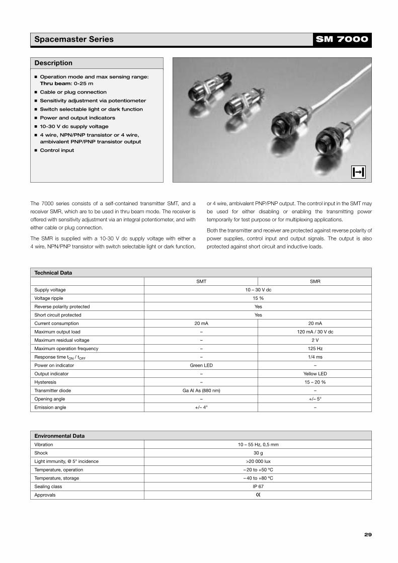
SM 7000Spacemaster Series
Description
� Operation mode and max sensing range:Thru beam: 0-25 m
� Cable or plug connection
� Sensitivity adjustment via potentiometer
� Switch selectable light or dark function
� Power and output indicators
� 10-30 V dc supply voltage
� 4 wire, NPN/PNP transistor or 4 wire,ambivalent PNP/PNP transistor output
� Control input
The 7000 series consists of a self-contained transmitter SMT, and a
receiver SMR, which are to be used in thru beam mode. The receiver is
offered with sensitivity adjustment via an integral potentiometer, and with
either cable or plug connection.
The SMR is supplied with a 10-30 V dc supply voltage with either a
4 wire, NPN/PNP transistor with switch selectable light or dark function,
or 4 wire, ambivalent PNP/PNP output. The control input in the SMT may
be used for either disabling or enabling the transmitting power
temporarily for test purpose or for multiplexing applications.
Both the transmitter and receiver are protected against reverse polarity of
power supplies, control input and output signals. The output is also
protected against short circuit and inductive loads.
Technical Data
SMT SMR
Supply voltage 10 – 30 V dc
Voltage ripple 15 %
Reverse polarity protected Yes
Short circuit protected Yes
Current consumption 20 mA 20 mA
Maximum output load – 120 mA / 30 V dc
Maximum residual voltage – 2 V
Maximum operation frequency – 125 Hz
Response time tON / tOFF – 1/4 ms
Power on indicator Green LED –
Output indicator – Yellow LED
Hysteresis – 15 – 20 %
Transmitter diode Ga Al As (880 nm) –
Opening angle – +/– 5°
Emission angle +/– 4° –
Environmental Data
Vibration 10 – 55 Hz, 0,5 mm
Shock 30 g
Light immunity, @ 5° incidence >20 000 lux
Temperature, operation – 20 to +50 ºC
Temperature, storage – 40 to +80 ºC
Sealing class IP 67
Approvals a
Telco_2000_catalogue 5/1/1904 4:02 pm Page 29

30
SM 7000 Spacemaster SeriesTr
ansm
itte
r
Type Power Control OutputConnection 5 m Cable 4 pin, M8 Plug 4 pin, M12 Plug
RangeSupply Feature Housing Material Housing Size Order Reference
7000
Polycarbonate
M18 x 1
SMT 7000 TP 5 SMT 7000 TP T4 SMT 7000 TP J
Stainless Steel SMT 7000 TS 5 SMT 7000 TS T4 SMT 7000 TS J
Available Types
Testinput
10-30 Vdc
Rec
eive
r
7620 NPN/PNP
Polycarbonate SMR 7620 TP 5 SMR 7620 TP T4 SMR 7620 TP J
Stainless Steel
M18 x 1
SMR 7620 TS 5 SMR 7620 TS T4 SMR 7620 TS J
7720 PNP/PNP
Polycarbonate SMR 7720 TP 5 SMR 7720 TP T4 SMR 7720 TP J
Stainless Steel SMR 7720 TS 5 SMR 7720 TS T4 SMR 7720 TS J
Sensitivitypot. andlight/dark
switch
0-25 metres
25 metres
Sensitivitypot.
Wiring Diagrams
Brown
Black
Blue
SMT 7000
1
4
3
Brown
White
Blue
SMR 7720
LoadsBlack
1
2
3
4PNP load, light operated on white wirePNP load, dark operated on black wire
Brown
White
Blue
SMR 7620 (load as NPN)
LoadBlack
*Do not connect black wire
1
2
3
4NC*
Brown
White
Blue
SMR 7620 (load as PNP)
LoadBlack
*Do not connect white wire
1
2
3
4NC*
on/off
Connections
Cable M8 Plug/Cable M12 Plug/Cable
Supply + Brown Pin 1/Brown Pin 1/Brown
Supply – Blue Pin 3/Blue Pin 3/Blue
Control/output Black Pin 4/Black Pin 4/Black
SMR output White Pin 2/White Pin 2/White
Sensor Plug(Male)
Cable Plug(Female)
12 4
3
1
324
Brown
Black
4
3
2
1
Sensor Plug(Male)
Cable Plug(Female)
2
1
4
3
Black
White
Brown
Blue
White
Blue
10-30 Vdc
4 pin, M8 4 pin, M12
Telco_2000_catalogue 5/1/1904 4:02 pm Page 30
31
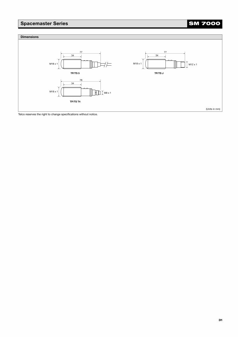
SM 7000Spacemaster Series
Dimensions
7734
M18 x 1
7734
M18 x 1 M12 x 1
7834
M18 x 1 M8 x 1
TP/TS 5 TP/TS J
TP/TS T4
(Units in mm)
Telco reserves the right to change specifications without notice.
Telco_2000_catalogue 5/1/1904 4:02 pm Page 31

32
Telco_2000_catalogue 5/1/1904 4:02 pm Page 32

Description
� Operation mode and max sensing range:Thru beam: 0-20 mDiffuse proximity: 0-50 cmRetro reflective: 0-3 mFibre: 0-75 cm
� Cable or plug connection
� Sensitivity adjustment via potentiometer
� Switch selectable light or dark function
� Power and output indicators
� High tolerance to hostile environments
� 10-30 V dc or 20-250 V ac supply voltage
� 3 wire, NPN or PNP transistor output or 2 wire, SCR output
The 8000 series consists of a self-contained transmitter SMT, and a
receiver SMR which are to be used in thru beam mode, an SMP for
diffuse proximity, SMRR for retro reflective and an SMPF for use with fibre
optic cables. All are offered with sensitivity adjustment via integral
potentiometer with either cable or plug connection.
The complete series is available either as 3 wire, NPN or PNP transistor
output with a 10-30 V dc supply voltage, or as 2 wire, SCR with a
20-250 V ac supply voltage both offering switch selectable light or dark
function. The control input in the 10-30 V dc SMT is intended to be used
for disabling or enabling the transmitting power temporarily for test
purpose or for multiplexing applications.
The dc series is protected against reverse polarity of power supplies,
control input and output signals. The output is protected against short
circuit and inductive loads.
Technical Data
SMTSMR
SMP/SMPF SMRR8x20 8x00
Supply voltage ac 20 – 250 V ac – 20 – 250 V ac
dc 10 – 30 V dc
Voltage ripple 15 %
Reverse polarity protected dc Yes
Short circuit protected dc – Yes
Current consumptionac 3 mA – 2 mA
dc 15 mA 5 mA 14 mA
Maximum output loadac
–200 mA
dc 120 mA @ 30 V dc
Maximum residual voltage ac
–8 V
dc 1,5 V
Max. operation frequency ac
–25 Hz
dc 250 Hz
Response time tON / tOFF
ac–
25 ms / 25 ms
dc 5 ms / 5 ms 2 ms / 2 ms
Power on indicator Green LED –
Output indicator – Yellow LED
Hysteresis – Approx. 10 – 30 % Approx. 3 – 10 %
Transmitter diode Ga Al As (880 nm) –
Opening angle – +/– 5° +/– 4° +/– 1,5°
Emission angle +/– 4° –
33
SM 8000Spacemaster Series
Telco_2000_catalogue 5/1/1904 4:03 pm Page 33

Tran
smit
ter
Ret
ro R
efle
ctiv
eFi
bre
Sen
sors
Pro
xim
ity
Rec
eive
rsSM 8000 Spacemaster Series
Type Power Control OutputConnection 5 m Cable 3 pin, M8 Plug 4 pin, M12 Plug
RangeSupply Feature Housing Material Housing Size Order Reference
8000 10 – 30 Test Polycarbonate SMT 8000 PG 5 SMT 8000 PG T3 SMT 8000 PG J
V dc Input Stainless SteelM18 x 1
SMT 8000 MG 5 SMT 8000 MG T3 SMT 8000 MG J
8600 20 – 250 –Polycarbonate SMT 8600 PG 5 – –
V ac Stainless Steel SMT 8600 MG 5 – –
8500 PNPPolycarbonate SMR 8500 PG 5 SMR 8500 PG T3 SMR 8500 PG J
Stainless Steel SMR 8500 MG 5 SMR 8500 MG T3 SMR 8500 MG J 0-7
8400 NPNPolycarbonate SMR 8400 PG 5 SMR 8400 PG T3 SMR 8400 PG J metres
Stainless Steel SMR 8400 MG 5 SMR 8400 MG T3 SMR 8400 MG J
8520 PNPPolycarbonate SMR 8520 PG 5 SMR 8520 PG T3 SMR 8520 PG J
Stainless Steel SMR 8520 MG 5 SMR 8520 MG T3 SMR 8520 MG J 0-20
8420 NPNPolycarbonate SMR 8420 PG 5 SMR 8420 PG T3 SMR 8420 PG J metres
Stainless Steel SMR 8420 MG 5 SMR 8420 MG T3 SMR 8420 MG J
8800 20 – 250 SCRPolycarbonate SMR 8800 PG 5 – – 7
V ac Stainless Steel SMR 8800 MG 5 – – metres
8500 PNPPolycarbonate SMP 8500 PG 5 SMP 8500 PG T3 SMP 8500 PG J
Stainless Steel SMP 8500 MG 5 SMP 8500 MG T3 SMP 8500 MG J
8400 NPNPolycarbonate SMP 8400 PG 5 SMP 8400 PG T3 SMP 8400 PG J
0-50 cmStainless Steel SMP 8400 MG 5 SMP 8400 MG T3 SMP 8400 MG J
8800 20 – 250 SCRPolycarbonate SMP 8800 PG 5 – –
V ac Stainless Steel SMP 8800 MG 5 – –
8500 PNPPolycarbonate SMPF 8500 PG 5 SMPF 8500 PG T3 SMPF 8500 PG J
Stainless Steel SMPF 8500 MG 5 SMPF 8500 MG T3 SMPF 8500 MG J
8400 NPNPolycarbonate SMPF 8400 PG 5 SMPF 8400 PG T3 SMPF 8400 PG J
Stainless Steel SMPF 8400 MG 5 SMPF 8400 MG T3 SMPF 8400 MG J
8800 20 – 250 SCRPolycarbonate SMPF 8800 PG 5 – –
V ac Stainless Steel SMPF 8800 MG 5 – –
8500 PNPPolycarbonate SMRR 8500 PG 5 SMRR 8500 PG T3 SMRR 8500 PG J
Stainless Steel SMRR 8500 MG 5 SMRR 8500 MG T3 SMRR 8500 MG J
8400 NPNPolycarbonate SMRR 8400 PG 5 SMRR 8400 PG T3 SMRR 8400 PG J 0-3
Stainless Steel SMRR 8400 MG 5 SMRR 8400 MG T3 SMRR 8400 MG J metres
8800 20 – 250 SCRPolycarbonate SMRR 8800 PG 5 – –
V ac Stainless Steel SMRR 8800 MG 5 – –
Available Types
20 metres
7 metres
10 – 30V dc
Sensitivitypot. andlight/dark
switch
Sensitivitypot. andlight/dark
switch
Light/darkswitch
Sensitivitypot. andlight/dark
switch
Sensitivitypot. andlight/dark
switch
M18 x 1
10 – 30V dc
M18 x 1
M18 x 1
10 – 30V dc
M18 x 1
10 – 30V dc
34
Note: Fibre optic cables to be ordered separately.
Note: Reflectors to be ordered separately.
Environmental Data
Vibration 10 – 55 Hz, 0,5 mm
Shock 30 g
Light immunity, @ 5° incidence SMR 8 x 00 >10 000 lux, SMR 8 x 20 > 7000 lux
Temperature, operation – 20 to +60 ºC
Temperature, storage – 40 to +80 ºC
Sealing classac IP 60
dc IP 67
Approvalsac a bc
dc a
Forrangesrefer to page 43
Telco_2000_catalogue 5/1/1904 4:03 pm Page 34

SM 8000Spacemaster Series
Wiring Diagrams
35
Brown
Black
Blue
Load
1
4
3
Brown
Blue Load
Brown
Blue
SMT 8600 SMR / SMPF / SMRR 8800
Brown
Black
Blue
SMR 8500
Load
SMP / SMPF / SMRR 8500
Brown
Red
Blue
SMT 8000
Brown
Blue
SMR 8800
Load
1
4
3
1
4
3
V ac Supply
ON/OFF Switch
Brown
Black
Blue
Load
1
4
3
Brown
Black
Blue
SMR 8400
Load
SMP / SMPF / SMRR 8400
1
4
3
V dc Supply
Connections
Cable M8 Plug/Cable M12 Plug/Cable
AC supply Blue & Brown – –
Supply + Brown Pin 1/Brown Pin 1/Brown
Supply – Blue Pin 3/Blue Pin 3/Blue
Control Red Pin 4/Black Pin 4/Black
SMR output Black Pin 4/Black Pin 3/Black
Sensor Plug(Male)
Cable Plug(Female)
Sensor Plug(Male)
Cable Plug(Female)
12 4
3
1
324
41
43 3 1
Black
Brown
Blue
Brown
Black
White
Blue
3 pin, M8 4 pin, M12
Telco_2000_catalogue 5/1/1904 4:03 pm Page 35

36
Dimensions
7834
M18 x 1 M8 x 1
7734
M18 x 1 M12 x 1
7545
M18 x 1
7734
M18 x 1
AC PG/MG 5 DC PG/MG T3
DC PG/MG JDC PG/MG 5
SM 8000 Spacemaster Series
(Units in mm)
Telco reserves the right to change specifications without notice.
Telco_2000_catalogue 5/1/1904 4:03 pm Page 36
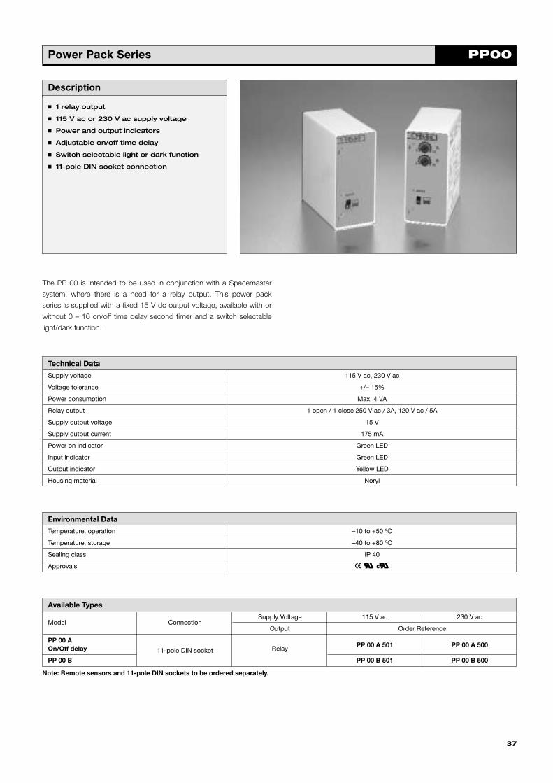
PP00Power Pack Series
Description
� 1 relay output
� 115 V ac or 230 V ac supply voltage
� Power and output indicators
� Adjustable on/off time delay
� Switch selectable light or dark function
� 11-pole DIN socket connection
The PP 00 is intended to be used in conjunction with a Spacemaster
system, where there is a need for a relay output. This power pack
series is supplied with a fixed 15 V dc output voltage, available with or
without 0 – 10 on/off time delay second timer and a switch selectable
light/dark function.
Technical Data
Supply voltage 115 V ac, 230 V ac
Voltage tolerance +/– 15%
Power consumption Max. 4 VA
Relay output 1 open / 1 close 250 V ac / 3A, 120 V ac / 5A
Supply output voltage 15 V
Supply output current 175 mA
Power on indicator Green LED
Input indicator Green LED
Output indicator Yellow LED
Housing material Noryl
Environmental Data
Temperature, operation –10 to +50 ºC
Temperature, storage –40 to +80 ºC
Sealing class IP 40
Approvals a bc
Available Types
Model ConnectionSupply Voltage 115 V ac 230 V ac
Output Order Reference
PP 00 A PP 00 A 501 PP 00 A 500On/Off delay 11-pole DIN socket Relay
PP 00 B PP 00 B 501 PP 00 B 500
37
Note: Remote sensors and 11-pole DIN sockets to be ordered separately.
Telco_2000_catalogue 5/1/1904 4:03 pm Page 37

PP00 Power Packs Series
Wiring Diagrams
3 4
C NO NC
5 9 7
NPN
PNP
82 10 1
Relay OutputSupply Voltage
NPN PNP
dc-output
Dimensions
35
76
13 74 35
76
13 73
38
PP 00 A PP 00 B
(Units in mm)(Units in mm)
Telco reserves the right to change specifications without notice.
Telco_2000_catalogue 5/1/1904 4:03 pm Page 38

Accessories
39
TRE
Light shutter with 1 mm hole.
Size: Ø 10.
Material: Polycarbonate.
TR 10S
Screw clamp.
Size: Ø 10.
Material: Polycarbonate.
TR 10KB
Mounting clip.
Size: Ø 10.
Material: Polycarbonate.
TREM 12
Light shutter with 1 mm hole.
Size: M12.
Material: Stainless Steel.
TREGM 12
Light shutter with 1 mm holewith protective glass cover.
Size: M12.
Material: Stainless Steel
TRLM
Lens.
Size: M12.
Material: Stainless Steel.
TRGM 12
Protective glass cover.
Size: M12.
Material: Stainless Steel.
TRPG 11
Light shutter (tubus).
Size: Ø 10.
Material: Stainless Steel.
TR 10M
Screw clamp.
Size: Ø 10.
Material: Brass.
TR 12M
Screw clamp.
Size: Ø 12.
Material: Brass.
TRWM
90° Prism.
Size: M12.
Material: Stainless Steel.
TR 11
Plug socket for PA photoamplifiers and PP PowerPacks
12
1 7
Ø10
Ø16 23
6
58
Ø5
Ø22
7,5
25
16
10Ø
12
M3
Ø3,
2
4
7,5
25
16
12Ø
15
Ø3,
2
4
M3
15,3
8 14
M12
x1
5
10,5
38
55
3
23
15
26
26
4
Ø6Ø32
Ø10
Ø65
10
26
Ø10
19,5
Ø8
25
6
M6
25
12,5
15
19,5
4,5
4
20
25
4,2
15,3
1 14
M12
x1
15,3
1 14
M12
x1
15,3
14
M12
x1
15,3
14
M12
x1
FA 18 SO
90° prism.
Size: M18.
Material: Polycarbonate.
2216
6,6Ø 15,6Ø 16,8
ILR 1Rectangular reflector.Size: 79 mm x 84 mm.
ILR 2Rectangular reflector.Size: 47 mm x 31 mm.
ILR 3
Circular reflector.
Size: 84 Ø.
84
79 8
47
31 7
84
7
TRGM 18
Protective glass cover.
Size: M18.
Material: Stainless Steel.
21
15
M18
x1
Telco_2000_catalogue 5/1/1904 4:03 pm Page 39

Accessories
Cables
Locking SealingConnector
Socket Type/Design Nut Class Material Length 3 pin, M8 4 pin, M8 4 pin, M12
Order reference
No ELKA K 3308 PVC5M S ELKA K 4408 PVC5M S —
Yes
IP 67 PVC 5m
ELKA KV 3308 PVC5M S ELKA KV 4408 PVC5M S ELKA KV 4412 PVC5M S
No ELWIKA K 3308 PVC5M R ELWIKA K 4408 PVC5M R —
Yes ELWIKA KV 3308 PVC5M R ELWIKA KV 4408 PVC5M R ELWIKA KV 4412 PVC5M R
40
Straight
RightAngle
Note: For PUR CABLE replace ‘PVC’ in the order reference with ‘PUR’. eg ELKA KV 4408 PUR5M R.Telco reserves the right to change specifications without notice.
Telco_2000_catalogue 5/1/1904 4:03 pm Page 40

41
Fibre Optics
Description
� Ideal for use in explosive areas
� Insensitive to electromagnetic and capacitive influence
� High temperature operation
� Various adaptor types
� Bifurcated or individual fibre construction
Technical Data
Cover Silicone
Sheath material Stainless Steel
Sealing IP 67
Strand diameter 50 µ m
Bundle diameter 1,0; 2,3; 3,5; 4,0; 4,5 mm
Opening angle 67 °
Adaptor Material Stainless Steel (V2A)
Bending Radius >5 x cover diameter
Temperature, Operation – 40 to +180 °C
Telco_2000_catalogue 5/1/1904 4:03 pm Page 41

Fibre Optics
Available types for Remote Photoelectric Systems
Sensing End Tip Dimensions Active ØAdaptor Sensing
Range Cable Length Order ReferenceType Mode
8 m 50 cm LLS 1306
4,0 A 6 m 1,5 m LLS 1326
7 m 1 m LLS 1308
4,5 B
70 cm 50 cm LYS 1309
60 cm 1 m LYS 1311
2,3 2.5 m 1,5 m LLS 1316
0,3 x 20
1,4 m 60 cm LLS 1374
1,25 m 1 m LLS 1368
Adaptor Type A – Individual Fibre Construction Adaptor Type B – Bifurcated Fibre Construction
15
29
Ø7,
5
Ø9
Ø6
15
29
Ø10 Ø
8
Ø12
Ø6,
7
Ø8 2515
37Ø4
10 25
11
7
25
11
Ø 6,7Ø 8
3,5
Ø 3,2
20
36
Ø15 M12 x 1
36Ø
15 M12 x 1
Note: Range specified using PA 11 in combination with remote sensor series 100.
42
(Units in mm)(Units in mm)
ThruBeam
ThruBeam
A
DiffuseProximity
Telco_2000_catalogue 5/1/1904 4:03 pm Page 42

43
Adaptors and AperturesAvailable types for SMPF 8000 Series
Sensing End Tip Dimensions Active Ø Adaptor Sensing Range Cable Length Order ReferenceType Mode
C 10 cm LLS 1300
1,0
LYS 1301
D 4 mm
LYS 1323
C 60 cm LLS 1304
D 2,5 cm LYS 1305
2,3
C 60 cm LLS 1302
D 2,5 cm LYS 1303
3,5
C 75 cm
60 cm
LLS 1310
D 6 cm LYS 1307
1,0
C 9 cm LLS 1312
D 3 mm LYS 1313
C 55 cm LLS 1314
D 2,5 cm LYS 1315
2,3
C 45 cm LLS 1318
D 2,5 cm LYS 1317
C 50 cm LLS 1362
0,3 x 20 D20 cm
LYS 1371
C 1,5 m LLS 1370
Adaptor Type C – Individual Fibre Construction Adaptor Type D – Bifurcated Fibre Construction
10 25
11
7
25
11
Ø 6,7Ø 8
3,5
Ø 3,2
20
15
25
4,2
Ø5
Ø1,
5
Ø1,
5
Ø2
55
951015
5
Ø6
Ø4,
2
Bendable Parts
15
39
Ø6,
7
M4
20
Ø8
15
39
Ø6,
7
Ø3,
5
12
Ø8
Ø5,
6
15
29
Ø7,
5
Ø9
Ø6
15
20
Ø4,
2
13
Ø6
Ø1,5
Ø6,
7
Ø8 2515
37Ø4
Ø8
Ø6,
7
35
Ø2,
3
4,5 7,5
Ø20
3025
M18 x 1
30
25
Ø20 M18 x 1
(Units in mm)(Units in mm)
Fibre Optics
ThruBeam
DiffuseProximity
ThruBeam
DiffuseProximity
ThruBeam
DiffuseProximity
ThruBeam
DiffuseProximity
ThruBeam
DiffuseProximity
ThruBeam
DiffuseProximity
ThruBeam
DiffuseProximity
ThruBeam
DiffuseProximity
ThruBeam
Telco reserves the right to change specifications without notice.
Telco_2000_catalogue 5/1/1904 4:03 pm Page 43

44
Telco_2000_catalogue 5/1/1904 4:03 pm Page 44
Capacity Load:
A load which is only or partially capacitive. An example is PLC inputs.
They are often noise protected by a capacitor. Another example is a long
pair of wires, where the capacity between the wires is significant.
Current Consumption:
The maximum current consumption for a unit when used at a specified
voltage supply, or at the maximum rated voltage supply.
Dark Function:
When referring to photoelectric systems, dark function means that the
output will be active ( a relay operates) when no light is received from the
transmitter.
Hysteresis:
An expression of the “inertness” of a system. For photoelectric systems
the hysteresis is measured as a difference between the distance where
sensors will see each other (L on) and the distance where they cannot
see each other any more (L off). The hysteresis is normally expressed as
a percentage of Lon.
Inductive Load Protection:
Protection of a transistor output stage against voltage peaks occuring
when an inductive load (relay, solenoid, coil) is switched off.
Inverting of Relay Function:
When inverting, the function will be opposite i.e. if the relay was
operated before, it will now be released.
Life Time:
The lifetime is defined as the time a unit can operate until the
performance decreases to a specified level. The lifetime will normally
depend on operation conditions such as temperature and humidity.
Light Function:
When referring to photoelectric systems, light function means that the
output will be active (a relay operates) when light is received from the
transmitter.
NPN output:
An output where the load is connected to a common positive supply rail.
Off delay:
The time delay between the absence (light mode operation) or presence
(dark mode operation) of the IR beam and turning the output off.
On delay:
The time delay between the presence (light mode operation) or absence
(dark mode operation) of the IR beam and turning the
output on.
Output Short Circuit Protection:
Protection of a transistor output stage against damaging current flow,
when the load is short circuited.
Output Load:
Normally meant as a pure resistive load.
PNP Output:
An output where the load is connected to a common negative
supply rail.
Residual Voltage:
When used in conjunction with outputs, it means the residual voltage
over the output circuit, when it is active. The residual voltage will
normally depend on the load current.
Response Time:
The time delay between an event taking place and the registration being
made. As an example, the time delay between a light beam in a photo-
electric system is interrupted and the output relay has operated. It is
often expressed in milliseconds (ms).
Reverse Polarity Protection:
Protection against wrong (reverse) connection to the supply wires.
Ripple:
Variation of the supply voltage with a frequency of 100 Hz (120 Hz).
Expressed as a percentage of the actual supply voltage.
Start Up Delay:
The time delay between power switched on and the unit functioning.
During this time the function can either be undefined or defined,
depending on the construction.
Test input:
To test the function of the sensor, the transmitter can, for example, be
switched off by a PLC in order to check whether the switching status
changes at the relay or transistor output.
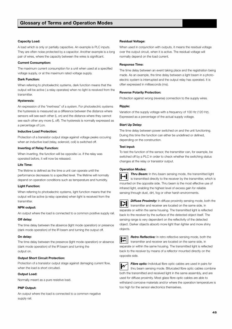
Operation Modes:
Thru Beam: In thru beam sensing mode, the transmitted light
is transmitted directly to the receiver by the transmitter, which is
mounted on the opposite side. Thru beam is the most effective use of
infrared light, enabling the highest level of excess gain for reliable
sensing through dust, dirt, fog or other harsh environments.
Diffuse Proximity: In diffuse proximity sensing mode, both the
transmitter and receiver are located on the same side, in
separate or within the same housing. The transmitted light is reflected
back to the receiver by the surface of the detected object itself. The
sensing range is very dependent on the reflectivity of the detected
object. Darker objects absorb more light than lighter and more shiny
objects.
Retro Reflective: In retro reflective sensing mode, both the
transmitter and receiver are located on the same side, in
separate or within the same housing. The transmitted light is reflected
back to the receiver by means of a reflector mounted directly on the
opposite side.
Fibre optic: Individual fibre optic cables are used in pairs for
thru beam sensing mode. Bifurcated fibre optic cables combine
both the transmitted and received light in the same assembly, and are
used for diffuse proximity. Most glass fibre optic cables are able to
withstand corrosive materials and/or where the operation temperature is
too high for the sensor electronics themselves.
45
Glossary of Terms and Operation Modes
Telco_2000_catalogue 5/1/1904 4:03 pm Page 45

46
Telco_2000_catalogue 5/1/1904 4:03 pm Page 46

47
SpaceGuard – Light Curtain Systems
Description SG09
� 79 crossed beams
� 0-4 metre sensing range
� Automatic sensitivity adjustment
� 24 V dc power supply
� Solid-state relay output
� Automatic time out
� LED indication of system status
� 50 000 lux extraneous light immunity
� Slim line detector housing (10x28 mm)
� Detector length, 2,00 m or 2,10 m
Description SG11
� 16 to 64 parallel light beams
� 0-5 metre sensing range
� Automatic or manual sensitivity adjustment
� 230 V ac, 115 V ac, 24 V ac or 24 V dc supply voltage
� Relay or NPN output
� Selectable time out
� LED indication of system status
� 10 000 lux extraneous light immunity
� Alarm and time out output
� Slim line (10x28 mm) or leading edge (37,5x13 mm) detector housing
� Detector length, 57 cm up to 2,10 m
Telco can offer a complete range of light curtain systems.
Please ask for your free SpaceGuard literature.
Telco_2000_catalogue 5/1/1904 4:03 pm Page 47

Telco’s dealers named by Telco Teams, or Exclusive Importers, Business Partners or
Distributors are not owned by Telco International Ltd. or any subsidiary of the holding
companies behind Telco Production. Therefore, and as such, they have absolutely no
authority to commit Telco International Ltd. or any subsidiary of the holding companies
behind Telco Production to any pledge, contract or agreement, application in any form, by
any means unless accepted beforehand by Telco International Ltd. or its subsidiaries.
Your local Telco Team
Telco_2000_catalogue 5/1/1904 4:03 pm Page 48