teip11-ps i/p signal converter for standard signals
TRANSCRIPT
Data Sheet 10/18-0.10-EN Rev. B
TEIP11-PS I/P signal converter for standard signals
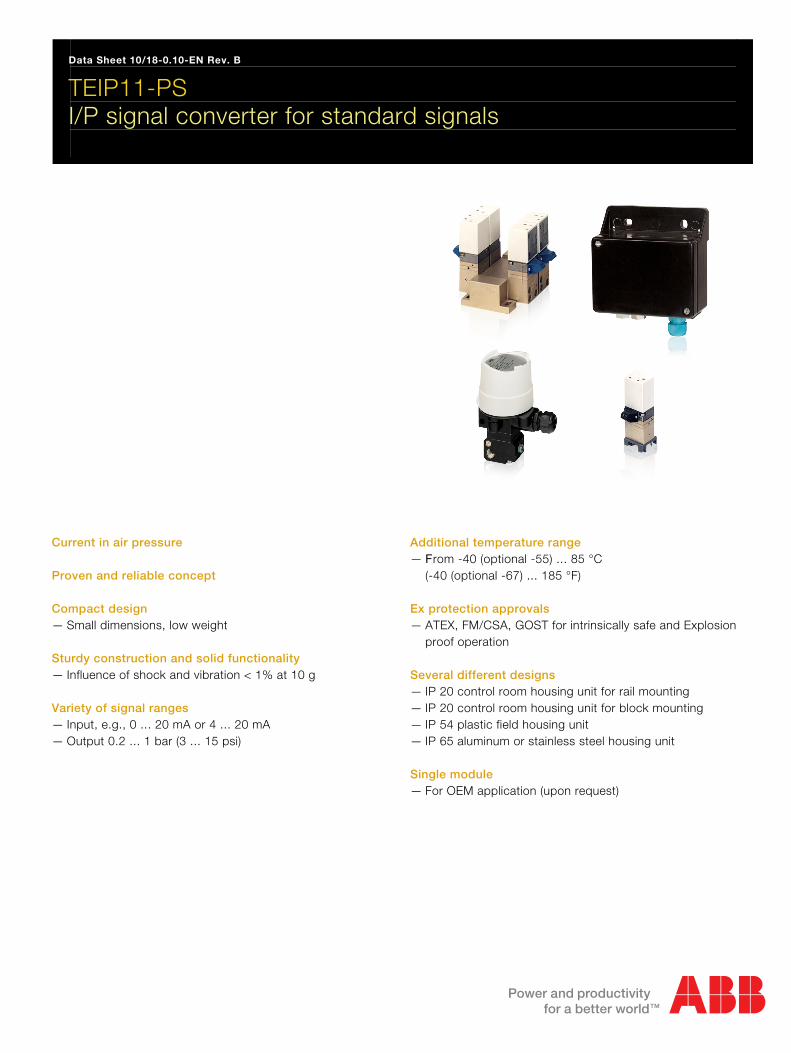
Current in air pressure Proven and reliable concept Compact design — Small dimensions, low weight Sturdy construction and solid functionality — Influence of shock and vibration < 1% at 10 g Variety of signal ranges — Input, e.g., 0 ... 20 mA or 4 ... 20 mA — Output 0.2 ... 1 bar (3 ... 15 psi)
Additional temperature range — From -40 (optional -55) ... 85 °C
(-40 (optional -67) ... 185 °F) Ex protection approvals — ATEX, FM/CSA, GOST for intrinsically safe and Explosion
proof operation Several different designs — IP 20 control room housing unit for rail mounting — IP 20 control room housing unit for block mounting — IP 54 plastic field housing unit — IP 65 aluminum or stainless steel housing unit Single module — For OEM application (upon request)
Contents
I/P signal converter for standard signals TEIP11-PS 10/18-0.10-EN Current 0 ... 20 mA / 4 ... 20 mA in air pressure 0.2 ... 1 bar (3 ... 15 psi)
2
Contents 1 Concept ................................................................................................................................................................3 2 Designs.................................................................................................................................................................3
2.1 Control room housing unit for rail mounting ...................................................................................................3 2.2 Control room housing unit for block mounting................................................................................................3 2.3 Field housing unit ...........................................................................................................................................3
3 Technical data......................................................................................................................................................4 3.1 Input (electric).................................................................................................................................................4 3.2 Output (pneumatic).........................................................................................................................................4 3.3 Power supply (pneumatic)..............................................................................................................................4 3.4 Transmission data and influences..................................................................................................................4 3.5 Operating conditions at installation site..........................................................................................................4 3.6 Environmental capabilities .............................................................................................................................5 3.7 Explosion protection .......................................................................................................................................5 3.8 Design for rail mounting .................................................................................................................................5 3.9 Design for block mounting..............................................................................................................................6 3.10 Design for field-mount housing (plastic).........................................................................................................6 3.11 Design for field-mount housing (aluminum / stainless steel)..........................................................................6 3.12 Accessories ....................................................................................................................................................6 3.13 Dimensioned drawings...................................................................................................................................7
4 Ordering information.........................................................................................................................................11 4.1 Additional ordering information ....................................................................................................................11 4.2 Order information, accessories ....................................................................................................................12 4.3 Order information, ball bearing designs .......................................................................................................12
Data Sheet I/P signal converter for standard signals
TEIP11-PS
Current 0 ... 20 mA / 4 ... 20 mA

I/P signal converter for standard signals TEIP11-PS 10/18-0.10-EN Current 0 ... 20 mA / 4 ... 20 mA in air pressure 0.2 ... 1 bar (3 ... 15 psi)
3
Wechsel ein-auf zweispaltig
1 Concept
The TEIP11-PS signal converter transforms electrical signals, e.g., 4 … 20 mA in 0.2 … 1 bar (3 ... 15 psi). It is therefore a connecting link between electrical/electronic and pneumatic systems. The signal conversion process is similar to the patented force balance method. Special features of the TEIP11-PS signal converter are its relatively small dimensions and outstanding operational stability when subject to shock and vibration. The converter can be subjected to loads up to 10 g with less than 1% effect on function. The housing units are available in a variety of models to meet your installation requirements. For potentially explosive conditions, units that offer intrinsically safe operation or Explosion proof encapsulation are available with international approval certificates for use worldwide. A variety of signal conversion ranges are available on the input and output sides (see chapter Technical data, page 4) For auxiliary power, compressed air at 1.4 bar (20 psi) may be required.
2 Designs
2.1 Control room housing unit for rail mounting
The control room housing unit for rail mounting is the easiest to use and lowest priced model in the signal converter line. A mounting base that is compatible with virtually all currently available EN rails is used for installation. The housing unit with plastic cap has an IP 20 protection class.
2.2 Control room housing unit for block mounting
The control room housing unit for block mounting enables you to install a number of converters in a small space. This design features central air supply via connection block and stop valves in the air connectors of the integrated signal converter. A maximum of 4 signal converters can be connected to the connection blocks required for block mounting. If necessary, 2 or 3 (or max. 4) connection blocks can be connected with each other to create block units of 4-8-12-16 signal converters. Stop valves allow you to mount or remove individual converters during operation.
2.3 Field housing unit
The field housing unit is designed for installation onsite or in the field. Housing units are available in the following models (and protection classes): plastic (IP 54), aluminum (IP 65) and stainless steel (IP 65). The units are suitable for wall mounting and 2"-pipe installation. A specially designed signal converter in plastic housing unit supports the use of combustible gas for auxiliary power instead of the standard compressed air.
M00350
1
2
34
Fig. 1
1 Control room housing unit for rail mounting 2 Control room housing unit for block mounting 3 Plastic field housing unit 4 Aluminum or stainless steel field housing unit
I/P signal converter for standard signals TEIP11-PS 10/18-0.10-EN Current 0 ... 20 mA / 4 ... 20 mA in air pressure 0.2 ... 1 bar (3 ... 15 psi)
4
3 Technical data Wechsel ein-auf zweispaltig
3.1 Input (electric)
Signal range 0 ... 20 mA or 4 ... 20 mA
0 ... 10 mA or 10 ... 20 mA
4 ... 12 mA or 12 ... 20 mA (additional ranges available upon request) Input resistance Ri = 260 Ω at 20 °C (68 °F), Tk + 0.4 %/K Overload limit 30 mA (see specifications “Explosion protection” for Ex devices) Capacitance/Inductance negligible
3.2 Output (pneumatic)
Signal range 0.2 ... 1 bar (3 ... 15 psi) Air capacity ≥kg/h = 4.1 Nm3/h = 2.4 scfm Load power acc. to VDE / VDI 3520 ≥ 0.95 kg/h = 0.9 Nm3/h = 0.5 scfm
3.3 Power supply (pneumatic)
Instrument air free of oil, water and dust acc. to DIN / ISO 8573-1 pollution and oil content according to Class 3 Pressure dew point 10 K below operating temperature Supply pressure 1.4 ± 0.1 bar (20 ± 1.5 psi) (with output 1 bar (15 psi)) Air consumption ≤ 0.2 kg/h = 0.16 Nm3/h = 0.1 scfm
3.4 Transmission data and influences
Characteristic linear, direct or reverse action Deviation: ≤ 0,5 % Hysteresis: ≤ 0,3 % Dead band ≤ 0,1 % Temperature ≤ 1% / 10 K within -20 ... 85 °C (-4 ... 185 °F) ≤ 2% / 10 K within -55 ... -20 °C (-67 ... -4 °F) Power supply ≤ 0.3% / 0.1 bar (1.5 psi) change in pressure Mechanical vibration ≤ 1% to 10 g and 20 ... 80 Hz Seismic vibration Meets requirements of DIN / IEC 68-3-3 Class III for strong and strongest earthquakes. Mounting orientation Zero point ≤ 0.4% at 90° change of position Step response
10 ... 90 % and 90 .... 10 % 0,6 s 5 ... 15 % and 15 ... 5 % 0,25 s
45 ... 55 % and 55 ... 45 % 0,2 s 85 ... 95 % and 95 ... 85 % 0,15 s
3.5 Operating conditions at installation site
Ambient temp. depending on the ordered model
-40 … 85 °C (-40 ... 185 °F)
-55 … 85 °C (-67 ... 185 °F) For Ex d -40 … 85 °C (-40 ... 185 °F)
Required protection
IP 20 For control room housing unit for rail or block mounting IP 54 For plastic housing IP 65 For aluminum or stainless steel field housing unit
Installation position any
I/P signal converter for standard signals TEIP11-PS 10/18-0.10-EN Current 0 ... 20 mA / 4 ... 20 mA in air pressure 0.2 ... 1 bar (3 ... 15 psi)
5
3.6 Environmental capabilities
Climate class GPF or FPF acc. to DIN 40040
Temperature -55 … 85 °C (-67 ... 185 °F) -45 … 85 °C (-49 ... 185 °F) for operation, storage or transport Relative humidity 75 % mean, 95 % short-term no condensation
3.7 Explosion protection aE
Explosion protection ATEX / GOST Russia / GOST Ukraine, intrinsically safe (all designs) 2G EEx ia IIC /T4/T5/T6 TÜV 1487x (for the control room housing and field housing unit) ATEX / GOST Russia / GOST Ukraine, flameproof (metal field housing only) EEx d IIC T4/T5/T6 Thermal specifications for explosion protection class Ex ia (doc no. 901068 or doc no. 901069) The following limit values for the temperature classes must be observed for the intrinsically safe versions:
Temperature class
Input current Ambient temp.
T6 T6 T5 T4 T5 T4 T5 T4 T4
50 mA 60 mA 60 mA 60 mA 100 mA 100 mA 120 mA 120 mA 150 mA
-55 … 60 °C(-67 ... 140 °F) -55 … 55 °C (-67 ... 131 °F) -55 … 70 °C (-67 ... 158 °F) -55 … 85 °C (-67 ... 185 °F) -55 … 55 °C (-67 ... 131 °F) -55 … 85 °C (-67 ... 185 °F) -55 … 45 °C (-67 ... 113 °F) -55 … 80 °C (-67 ... 176 °F) -55 … 70 °C (-67 ... 158 °F)
Thermal specifications for explosion protection class Ex d The following limit values for the temperature classes must be observed for Ex d versions (doc. no. 900771):
Temperature class
Input current Ambient temp.
T6 T5 T4
50 mA 50 mA 40 mA
-40 … 55 °C (-40 ... 131 °F) -40 … 70 °C (-40 ... 158 °F) -40 … 85 °C (-40 ... 185 °F)
FM "intrinsically safe" (not for metal field housing units) I.S.: CL I / Div 1 / Grp A B C D N.I.: CL I / Div 2 / Grp A B C D
FM “intrinsically safe” (for metal field housing units only) I.S.: CL I-II-II / Div 1 / Grp A B C D E F G N.I.: CL I / Div 2 / Grp A B C S.: CL II / Div 2 / Grp G S.: CL III / Div 2 FM "explosion proof" (for metal field housing units only) X.P.: CL I / Div 1 / Grp A B C D D.I.P.: CL II III / Div 2 / Grp E F G CSA “intrinsically safe” (not for metal field housing units) I.S.: CL I / Div 1 / Grp A B C D CL I / Div 2 / Grp A B C D
CSA “intrinsically safe” (for metal field housing units only) I.S.: CL I / Div 1 / Grp A B C D CL II / Div 1 / Grp E F G CL III CL I / Div 2 / Grp A B C D CL II / Div 2 / Grp E F G CSA “explosion proof” (for metal field housing units only) IX.P.: CL I / Div 1 / Grp B C D CL II / Div 2 / Grp E F G Gost Explosion protection requirements ATEX EEx ia or EEx d FM/CSA intrinsically safe FM/CSA explosion proof GOST EEx ia or EEx d (Russia / Ukraine) Other explosion protection certificates on request
3.8 Design for rail mounting
Material/protection Housing IP 20 aluminum with plastic cap Mounting Rail mounting EN 50022 - 35 x 7,5
EN 50035 - G 32
EN 50045 - 15 x 5 Electrical connection 2-pole screw terminal for 2.5 mm2 (14 AWG) Pneumatic connection two 1/8 NPT threads for air supply and output Weight 0,25 kg (0.55 lb) Dimensions Refer to dimensioned drawings
I/P signal converter for standard signals TEIP11-PS 10/18-0.10-EN Current 0 ... 20 mA / 4 ... 20 mA in air pressure 0.2 ... 1 bar (3 ... 15 psi)
6
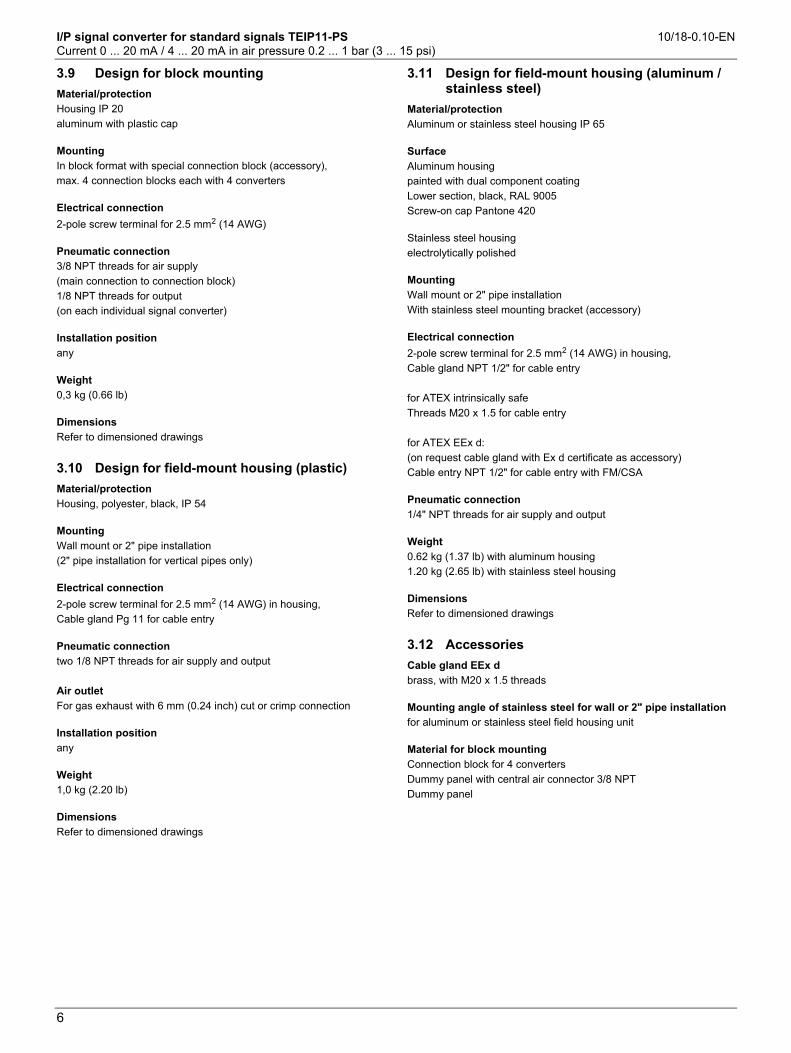
3.9 Design for block mounting
Material/protection Housing IP 20 aluminum with plastic cap Mounting In block format with special connection block (accessory), max. 4 connection blocks each with 4 converters Electrical connection 2-pole screw terminal for 2.5 mm2 (14 AWG) Pneumatic connection 3/8 NPT threads for air supply (main connection to connection block) 1/8 NPT threads for output (on each individual signal converter) Installation position any Weight 0,3 kg (0.66 lb) Dimensions Refer to dimensioned drawings
3.10 Design for field-mount housing (plastic)
Material/protection Housing, polyester, black, IP 54 Mounting Wall mount or 2" pipe installation (2" pipe installation for vertical pipes only) Electrical connection 2-pole screw terminal for 2.5 mm2 (14 AWG) in housing, Cable gland Pg 11 for cable entry Pneumatic connection two 1/8 NPT threads for air supply and output Air outlet For gas exhaust with 6 mm (0.24 inch) cut or crimp connection Installation position any Weight 1,0 kg (2.20 lb) Dimensions Refer to dimensioned drawings
3.11 Design for field-mount housing (aluminum / stainless steel)
r
Material/protection Aluminum or stainless steel housing IP 65 Surface Aluminum housing painted with dual component coating Lower section, black, RAL 9005 Screw-on cap Pantone 420 Stainless steel housing electrolytically polished Mounting Wall mount or 2" pipe installation With stainless steel mounting bracket (accessory) Electrical connection 2-pole screw terminal for 2.5 mm2 (14 AWG) in housing, Cable gland NPT 1/2" for cable entry for ATEX intrinsically safe Threads M20 x 1.5 for cable entry for ATEX EEx d: (on request cable gland with Ex d certificate as accessory) Cable entry NPT 1/2" for cable entry with FM/CSA Pneumatic connection 1/4" NPT threads for air supply and output Weight 0.62 kg (1.37 lb) with aluminum housing 1.20 kg (2.65 lb) with stainless steel housing Dimensions Refer to dimensioned drawings
3.12 Accessories
Cable gland EEx d brass, with M20 x 1.5 threads Mounting angle of stainless steel for wall or 2" pipe installation for aluminum or stainless steel field housing unit Material for block mounting Connection block for 4 converters Dummy panel with central air connector 3/8 NPT Dummy panel
Wechsel ein-auf zweispaltig

I/P signal converter for standard signals TEIP11-PS 10/18-0.10-EN Current 0 ... 20 mA / 4 ... 20 mA in air pressure 0.2 ... 1 bar (3 ... 15 psi)
7
3.13 Dimensioned drawings
3.13.1 Design for control room housing unit for rail mounting
M00323
36
(1.4
2)
20 (0.79) 32 (1.26)
3(0
.12)
Ø 3,3 (0.13)
Ø 3,3 (0.13)
20 (0.79)
36 (1.42)
40
(1.5
7)
25
(0.9
8)
97
(3.8
2)
1
1
4
3
2 5
Fig. 2: Dimensions in mm (inch) 1 Electrical connections 2 Filter 3 Output
4 Supply air 5 Mounting bracket for DIN rails

I/P signal converter for standard signals TEIP11-PS 10/18-0.10-EN Current 0 ... 20 mA / 4 ... 20 mA in air pressure 0.2 ... 1 bar (3 ... 15 psi)
8
3.13.2 Control room housing unit for block mounting
M00320
12,4 (0.49)
n x 80 (3.15)3)
80 (3.15)
25 (0.98)
115
(4.5
3)
2)
7,5
(0.3
0)
25 (0.98)
40
(1.5
7)
10
(0.3
9)
4
1
2
3
5
7
6
80
(3.1
5)
64
(2.5
2)
6,4
(0.2
5)
50
(1.9
7)
115
(4.5
3)
20,5
(0.8
1)
6,4 (0.25)
Fig. 3: Dimensions in mm (inch) 1 Output 5 Panel with central air connector 2 Supply air 6 Mounting block 3 Filter 7 Dummy panel
4 Electrical connections 1) Design 0.2 ... 1 bar (2.90 ... 14.50 psi)
2) Design 0.4 ... 1 bar (5.80 ... 14.50 psi)
3) Length 80 mm (3.15 inch) for each mounting block

I/P signal converter for standard signals TEIP11-PS 10/18-0.10-EN Current 0 ... 20 mA / 4 ... 20 mA in air pressure 0.2 ... 1 bar (3 ... 15 psi)
9
3.13.3 Design for field-mount housing (plastic)
Ø66 (2.60)
100
(3.9
4)
94
(3.7
0)
69 (2.72)
35 (1.38)
24,5 (0.96)
128 (5.04)
128
(5.0
4)
20
(0.7
9)
98,5 (3.88)
69 (2.72)
25 (0.98)
20 (0.79)
72 (2.83)
7 (0.28)
1
2
34
M00321 Fig. 4: Dimensions in mm (inch) 1 Electrical connections 3 Supply air 2 Connection only with design for operation with combustible gas
for diverting the escaping gas / 6 mm (0.24) screw terminal connection
4 Output
I/P signal converter for standard signals TEIP11-PS 10/18-0.10-EN Current 0 ... 20 mA / 4 ... 20 mA in air pressure 0.2 ... 1 bar (3 ... 15 psi)
10
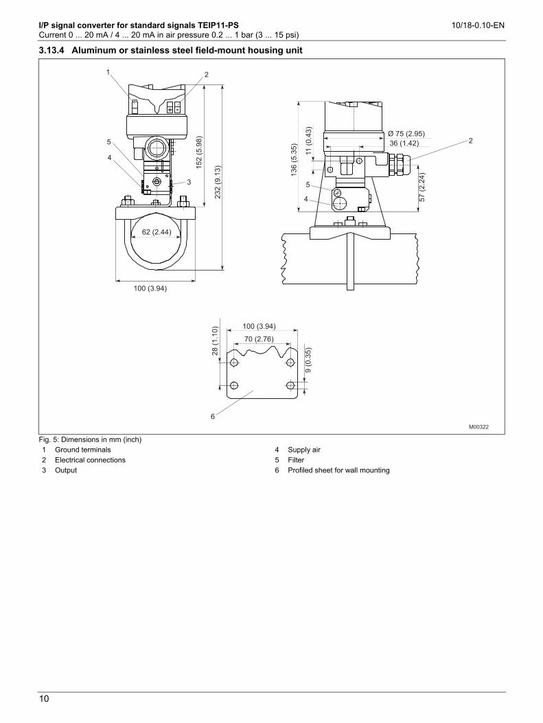
3.13.4 Aluminum or stainless steel field-mount housing unit
100 (3.94)
Ø 75 (2.95)
36 (1.42)
62 (2.44)
100 (3.94)
152
(5.9
8)
232
(9.1
3)
136
(5.3
5)
11
(0.4
3)
57
(2.2
4)
70 (2.76)
28
(1.1
0)
9(0
.35)
1 2
3
4
5
5
4
2
6
M00322 Fig. 5: Dimensions in mm (inch) 1 Ground terminals 2 Electrical connections 3 Output
4 Supply air 5 Filter 6 Profiled sheet for wall mounting
I/P signal converter for standard signals TEIP11-PS 10/18-0.10-EN Current 0 ... 20 mA / 4 ... 20 mA in air pressure 0.2 ... 1 bar (3 ... 15 psi)
11
Order information
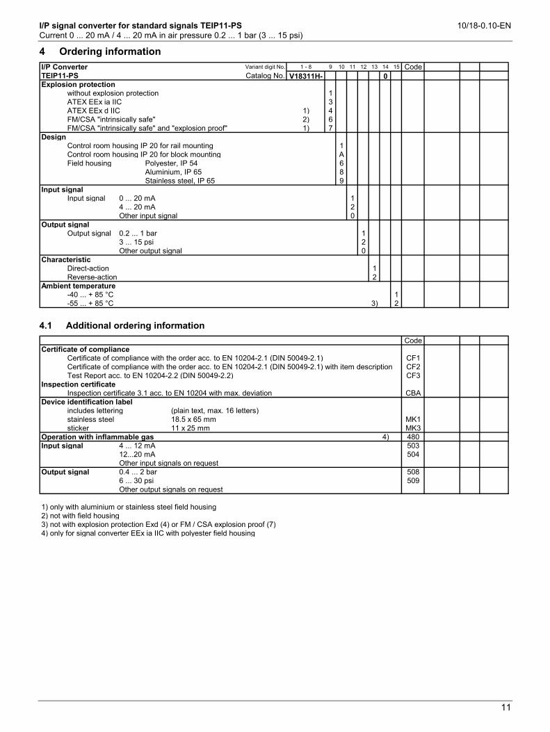
4 Ordering information
I/P Converter Variant digit No. 1 - 8 9 10 11 12 13 14 15 CodeTEIP11-PS Catalog No. V18311H- 0Explosion protection
without explosion protection 1ATEX EEx ia IIC 3ATEX EEx d IIC 1) 4FM/CSA "intrinsically safe" 2) 6FM/CSA "intrinsically safe" and "explosion proof" 1) 7
DesignControl room housing IP 20 for rail mounting 1Control room housing IP 20 for block mounting AField housing Polyester, IP 54 6
Aluminium, IP 65 8Stainless steel, IP 65 9
Input signalInput signal 0 ... 20 mA 1
4 ... 20 mA 2Other input signal 0
Output signalOutput signal 0.2 ... 1 bar 1
3 ... 15 psi 2Other output signal 0
CharacteristicDirect-action 1Reverse-action 2
Ambient temperature-40 ... + 85 °C 1-55 ... + 85 °C 3) 2
4.1 Additional ordering information
CodeCertificate of compliance
Certificate of compliance with the order acc. to EN 10204-2.1 (DIN 50049-2.1) CF1Certificate of compliance with the order acc. to EN 10204-2.1 (DIN 50049-2.1) with item description CF2Test Report acc. to EN 10204-2.2 (DIN 50049-2.2) CF3
Inspection certificateInspection certificate 3.1 acc. to EN 10204 with max. deviation CBA
Device identification labelincludes lettering (plain text, max. 16 letters)stainless steel 18.5 x 65 mm MK1sticker 11 x 25 mm MK3
Operation with inflammable gas 4) 480Input signal 4 ... 12 mA 503
12...20 mA 504Other input signals on request
Output signal 0.4 ... 2 bar 5086 ... 30 psi 509Other output signals on request
1) only with aluminium or stainless steel field housing2) not with field housing3) not with explosion protection Exd (4) or FM / CSA explosion proof (7)4) only for signal converter EEx ia IIC with polyester field housing

I/P signal converter for standard signals TEIP11-PS 10/18-0.10-EN Current 0 ... 20 mA / 4 ... 20 mA in air pressure 0.2 ... 1 bar (3 ... 15 psi)
12
Bestellangaben
4.2 Order information, accessories
TEIP11-PS Catalog No. CodeCable gland EEx d, brass, M 20x1.5 thread 319343Mounting bracket, stainless steel for wall mounting 319344
for wall or 2" pipe mounting 319345(for mounting the aluminium or stainless steel field housing)Parts for block mounting
Connection block for 4 converters 4) 7958243Termination block with central supply air connection 3/8 NPT 7958251Termination block without connection 7958245
Bestellangaben
4.3 Order information, ball bearing designs
Catalog No. CodeI/P Converter TEIP11-PSControl room housing IP 20 for rail mountingExplosion protection Input Outputwithout 0 ... 20 mA 0.2 ... 1 bar V18311H - 1111101
3 ... 15 psi V18311H - 11121014 ... 20 mA 0.2 ... 1 bar V18311H - 1121101
3 ... 15 psi V18311H - 1122101ATEX EEx ia IIC 0 ... 20 mA 0.2 ... 1 bar V18311H - 3111101
3 ... 15 psi V18311H - 31121014 ... 20 mA 0.2 ... 1 bar V18311H - 3121101
Field housingExplosion protection Material Input Outputwithout Polyester 4 ... 20 mA 0.2 ... 1 bar V18311H - 1621101
3 ... 15 psi V18311H - 1622101Aluminium 4 ... 20 mA 0.2 ... 1 bar V18311H - 1821101
3 ... 15 psi V18311H - 1822101ATEX EEx ia IIC Polyester 4 ... 20 mA 0.2 ... 1 bar V18311H - 3621101
3 ... 15 psi V18311H - 3622101Aluminium 4 ... 20 mA 0.2 ... 1 bar V18311H - 3821101
3 ... 15 psi V18311H - 3822101Stainless steel 4 ... 20 mA 0.2 ... 1 bar V18311H - 3921101
ATEX EEx d IIC Aluminium 4 ... 20 mA 0.2 ... 1 bar V18311H - 48211013 ... 15 psi V18311H - 4822101
Stainless steel 4 ... 20 mA 0.2 ... 1 bar V18311H - 4921101
4) up to 4 connection blocks can be fitted together to block units carrying 4-8-12-16 converters


Contact us
10/1
8-0.
10-E
NR
ev.B
12.2
010
|3K
XE31
1001
R10
01ABB Ltd. Process Automation Salterbeck Trading Estate Workington, Cumbria CA14 5DS UK Phone: +44 (0)1946 830 611 Fax: +44 (0)1946 832 661 ABB Inc. Process Automation 125 E. County Line Road Warminster, PA 18974 USA Phone: +1 215 674 6000 Fax: +1 215 674 7183 ABB Automation Products GmbH Process Automation Schillerstr. 72 32425 Minden Germany Phone: +49 551 905-534 Fax: +49 551 905-555 www.abb.com
Note We reserve the right to make technical changes or modify the contents of this document without prior notice. With regard to purchase orders, the agreed particulars shall prevail. ABB does not accept any responsibility whatsoever for potential errors or possible lack of information in this document. We reserve all rights in this document and in the subject matter and illustrations contained therein. Any reproduction, disclosure to third parties or utilization of its contents - in whole or in parts – is forbidden without prior written consent of ABB. Copyright© 2010 ABB All rights reserved