tecnai t12 operating procedures - university of minnesota · revised 3/08/2017 1 tecnai t12...
TRANSCRIPT
Revised 3/08/2017 1
Tecnai T12 Operating Procedures I. Initial Procedures 1 II. Accelerating Voltage 3 III. Specimen Loading and Holder Insertion/Removal 3 IV. Emission Current 7 V. Alignment 7 VI. Camera Control and Imaging 14 VII. End of Session 16 VIII. Troubleshooting 17 IX. Addenda 22
I. Initial Procedures
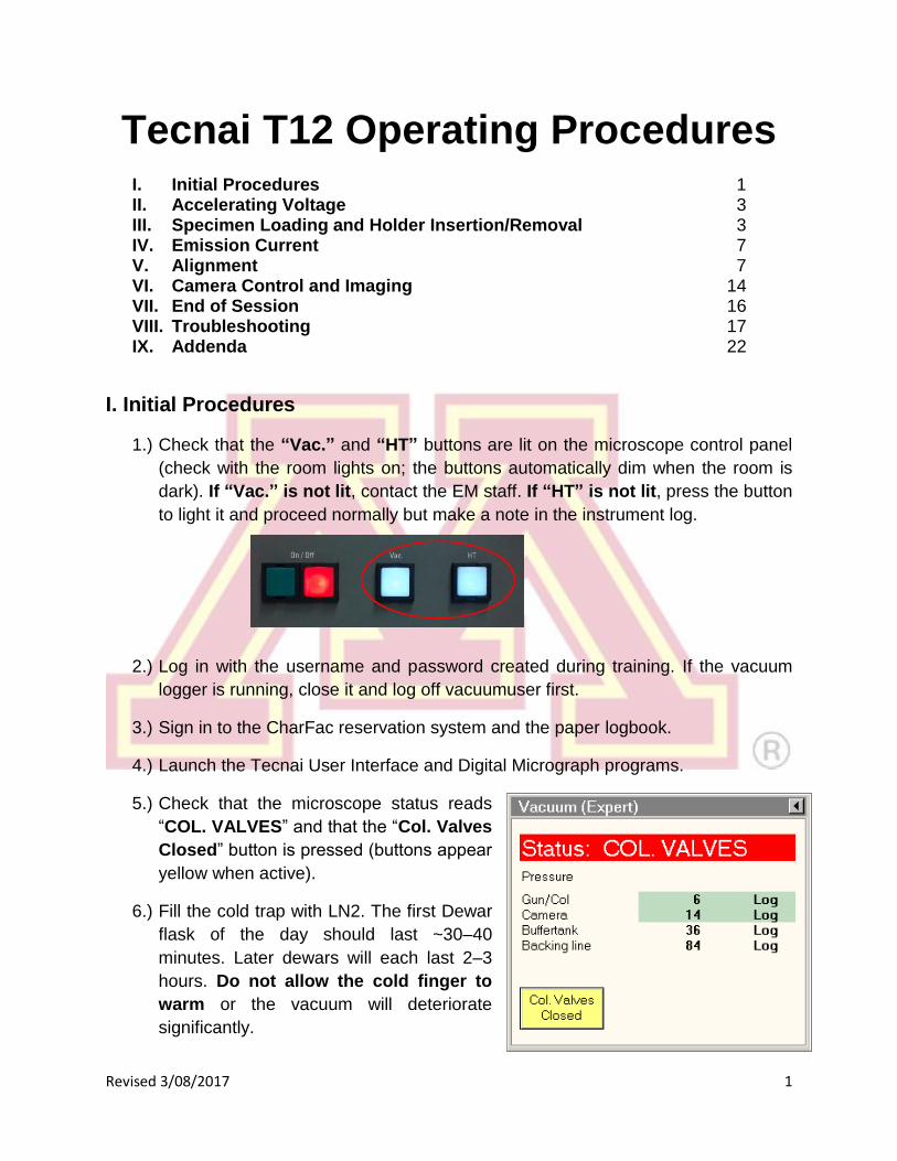
1.) Check that the “Vac.” and “HT” buttons are lit on the microscope control panel
(check with the room lights on; the buttons automatically dim when the room is
dark). If “Vac.” is not lit, contact the EM staff. If “HT” is not lit, press the button
to light it and proceed normally but make a note in the instrument log.
2.) Log in with the username and password created during training. If the vacuum
logger is running, close it and log off vacuumuser first.
3.) Sign in to the CharFac reservation system and the paper logbook.
4.) Launch the Tecnai User Interface and Digital Micrograph programs.
5.) Check that the microscope status reads
“COL. VALVES” and that the “Col. Valves
Closed” button is pressed (buttons appear
yellow when active).
6.) Fill the cold trap with LN2. The first Dewar
flask of the day should last ~30–40
minutes. Later dewars will each last 2–3
hours. Do not allow the cold finger to
warm or the vacuum will deteriorate
significantly.

Revised 3/08/2017 2
IGP1 indicates the vacuum level in
the column and gun chamber. It
should read 6 when the cold finger
is chilled.
7.) Open the “Vacuum Overview” screen by selecting it from the box in the bottom
right corner of the screen. Check that IGP1 (Gun/Col) reads ~6 (log units).
P3 indicates the camera vacuum
level. It should read < 25.
P1 indicates the pressure in the
buffer tank, and P2 the pressure in
the backing pump line.
This dialogue box is used to select
the vacuum overview (or any of
several other information or setup
tabs).

Revised 3/08/2017 3
II. Accelerating Voltage
1.) If the “High Tension” button is lit and the displayed value reads 120 kV,
proceed to Section III.
2.) The “High Tension" will be turned off (grey) for
the first user each day. IGP1 must read < 10
before proceeding (see Section I).
3.) If the “High Tension” button is unavailable (grey
with faded text), check that “HT” is lit on the
microscope control panel (Section I). If not,
press it once to light it.
4.) Select 20 kV using the slider in the “High
Tension” control, then turn on the “High
Tension” button. The emission current
(“Emission” in the “Filament” control) will spike
and then stabilize to ~0.5–1 µA.
5.) Wait 1–2 minutes before proceeding, and then
raise the slider to 40 kV. Continue in 20 kV
increments, waiting 1–2 min at each. If the
emission current remains high (>1–2 µA), return
to the previous step for several minutes.
Note: The HT may switch off and become disabled
when reaching 40 kV. If this occurs, simply press the main “HT” console button to
re-enable it (see Section I), click the “High Tension” again at 40 kV, and continue.
III. Specimen Loading and Holder Insertion/Removal
Note: the specimen holder, airlock, and compu-stage are made up of delicate,
precisely machined components. You should never have to exert significant
force during any step of this procedure. Doing so may result in serious
damage to the instrument or holder.
1.) Before inserting or removing the sample holder, make sure that the column
valves are closed, the objective aperture is not inserted, and the holder has
been reset. The stage is reset by using the “Search” tab, “Stage” (flapout),
“Reset: Holder” button.

Revised 3/08/2017 4
2.) Sample Holder Removal:
a.) Reset the sample stage.
b.) Always keep light pressure on the purple goniometer surface when
removing the sample holder. Pull the holder straight back without rotating
until it stops moving.
c.) Rotate the holder clockwise until it stops. This rotation moves the guide pin
(see steps 3 and 4) approximately from the 12 o’clock position to 5 o’clock.
d.) Gently, while keeping pressure on the goniometer, pull the sample holder
back to break the airlock vacuum. This will require a small amount of force.
e.) Remove the holder straight back out of the column while being careful not to
scrape it along the inside of the airlock.
f.) Be careful not to touch the holder o-ring or any part past it with bare hands.

Revised 3/08/2017 5
3.) Specimen Loading:
Note: Never mount magnetic specimen discs in the clamp holder. The clamp
spring is not strong enough to prevent the specimen from attaching to the objective
lens polepiece.
a.) Place the sample holder in the protective stand.
b.) Remove the sample loading tool from the base of the stand.
c.) Using one hand to prevent the holder from slipping out of the stand, insert the
tool into the hole in the specimen clamp and gently raise the clamp straight
up until it stops.
d.) Place the specimen grid into the recess
at the end of the holder.
e.) Gently lower the clamp straight down
to hold the grid securely. Return the tool
to the base of the holder stand.
f.) Retract the holder slightly and turn it
upside down. Tap the back end several
times, then turn the holder upright and
check that the grid has not moved
(movement suggests the grid is not
properly secured).
g.) Use the microscope to inspect the holder o-ring for debris. Gently remove any
debris using a sheet of lens paper.
Sample rod in protective stand
Sample loading tool
(stored in base)
Sample location
and clamp

Revised 3/08/2017 6
4.) Sample Holder Insertion:
a.) Carefully line the pin on the sample holder with the 5 o’clock position on the
goniometer and gently insert the holder until it stops. Be careful not to
scrape the tip. You should feel some resistance as the holder o-ring seats in
the airlock chamber.
b.) The airlock will begin pumping, and the red
light on the compu-stage will go on. Do not
move the holder while the red stage
LED is lit.
c.) The pumping time remaining will be visible
in the Vacuum Overview window.
d.) Select the specimen holder type (Single
Tilt) from the box in the interface. Be sure
to click the button to confirm the
selection.
e.) When the pump times ends (status reads “COL. VALVES”) and the red
stage LED goes out, support the purple goniometer surface with one hand
and grip the holder securely with the other. Slowly rotate the holder
counterclockwise from 5 o’clock to 12 o’clock.
Sample holder pin
Red stage LED

Revised 3/08/2017 7
f.) Gently allow the holder to slide into the microscope column until it stops. Tap
the end of the holder to make sure it is securely seated.
IV. Emission Current
1.) In the “Filament” window, set the
“Heat To” value to the desired
cathode temperature (consult the log
sheet for recently used settings). If a
change was made, click the button
to confirm.
2.) Click the “Filament” button. It will turn
yellow and the filament will begin
automatically heating to the selected
temperature.
Note: The emission “Step” setting controls the bias voltage on the Wehnelt cylinder.
A higher step value decreases the bias. This produces more emission current but
increases the energy spread and source size of the beam.
V. Alignment
Note: Align the microscope from the top (gun) down. Press F1 at any time for online
help with an alignment. Begin with the objective and SA apertures removed. Leave a
condenser aperture inserted to avoid specimen damage from high beam intensity.
Left control pad (LC) Right control pad (RC)
Controls beam shift (trackball),
beam intensity, stigmators, sample
tilt, and multifunction (MF) X.
Controls stage position (trackball),
Z-height, focus, magnification,
multifunction (MF) Y, and selecting
diffraction/imaging mode

Revised 3/08/2017 8
1.) Finding the Beam
a.) Click the “Col. Valves Closed” button to open the column valves (button
turns grey and status becomes “Ready”)
i.) If no beam is visible, try decreasing the magnification (RC “Magnification”)
or moving the specimen stage (RC trackball), in case a grid bar is blocking
the beam path.
ii.) If these steps fail, see Troubleshooting (Section VIII).
2.) Gun Tilt
a.) Set the microscope magnification (RC
“Magnification”) in the 10−60 kx range
and set “Spot size” to 3.
b.) Center the beam using the beam shift
(LC trackball) and spread the beam (LC
“Intensity”) clockwise from crossover to
~3/4 the size of the screen.
Note: If the beam is very asymmetrical,
roughly adjust the condenser stigmation
(see step 5).
c.) Select “Gun Tilt” from the “Direct
Alignments” panel in the “Tune”
workspace.
d.) Adjust the gun tilt using the
multifunction (MF) knobs (LC & RC) to
produce the brightest beam by
minimizing the Exposure time. The
sensitivity of both MF knobs is controlled
by the +/− buttons (LC).
e.) Press “Done” in “Direct Alignments”.

Revised 3/08/2017 9
3.) Gun Shift
a.) Select “Gun Shift” from the “Direct Alignments” panel.
b.) Set the “Spot size” to 9.
c.) Converge the beam to crossover using the “Intensity” (LC) knob and center
the beam using the beam shift trackball (LC)
Note: if the beam moves significantly when changing the intensity, roughly
center the condenser aperture (see step 4.) before proceeding.
d.) Set the “Spot Size” to 3.
e.) Converge the beam to crossover and center the beam using the gun shift
(MF knobs).
f.) Repeat steps b–e until the beam does not move when changing between
spot sizes 3 and 9.
g.) Press “Done” in “Direct Alignments”.
h.) If the gun shift must be adjusted a substantial amount and it results in a
significant change in the measured exposure time at a given spot size, re-
check the gun tilt alignment.
4.) Centering the Condenser Aperture
a.) Select the desired condenser
aperture (4 is largest; 1 is
smallest) using the large, outer
knob on the aperture.
b.) Converge the beam to crossover
(LC “Intensity”) and center the
beam using the beam shift
trackball (LC).
c.) Spread the beam (“Intensity”
clockwise from crossover) and
center the illuminated area using
the X and Y knobs on the
aperture (not MF knobs)
d.) Repeat steps b and c until the beam spreads evenly across the screen.
Aperture selection
X and Y alignments
Insert/remove
aperture

Revised 3/08/2017 10
5.) Condenser Astigmatism
Note: Condenser lens astigmatism should be corrected when the beam does not
expand in a symmetrical, circular fashion when the “Intensity” knob is adjusted.
Astigmatism must be corrected separately for each spot size that is used.
a.) Converge the beam to crossover (LC “Intensity”) and center it with the beam
shift (LC trackball).
b.) Select “Condenser” on the
“Stigmator” control panel (the panel
can also be brought up by pressing
the “Stigmator” (LC) button).
c.) Spread the beam and use the MF
knobs to make the beam as circular
as possible.
d.) Select “None” on the “Stigmator”
panel (or press the LC “Stigmator”
button) to end stigmator control.
6.) Specimen Height Adjustment
Note: all alignments beyond this point depend on the objective focus. To ensure
proper alignment, both the specimen and objective lens focus must lie on the
eucentric plane of the microscope. This step will position the specimen.
a.) Find a point of interest on the specimen using the stage trackball (RC).
b.) Activate the “Alpha wobbler” (LC button L2, by default). The stage will begin
rocking through a tilt range of +/− 15°.
c.) Minimize the specimen movement by adjusting the “Z-axis” control buttons
(RC). These buttons are pressure sensitive; pressing harder = faster change.
d.) Deactivate the “Alpha wobbler”.
Alternatively: the eucentric height can also be set by using the “Eucentric
focus” button (RC) to focus the objective lens on the eucentric plane. The
specimen can then be brought into focus using the “Z-axis” buttons. When it is in
focus, it is located at the eucentric plane of the microscope.

Revised 3/08/2017 11
7.) Beam Tilt Pivot Points
a.) Focus (RC “Focus”) the specimen to minimum contrast.
Note: the “Focus” knob has two parts. The smaller,
inner knob changes the focus. The larger, outer knob
adjusts the “Focus step” i.e., how much the focus
changes with each movement of the inner knob.
b.) Move to a non-beam-sensitive area of the
sample. Converge (LC “Intensity”) the beam to
crossover and center it (LC trackball).
c.) Select “Beam tilt pp X” from “Direct Alignments”.
d.) Use the MF knobs to superimpose the two beam
spots and minimize the beam movement.
e.) Press “Done” in “Direct Alignments”.
f.) Repeat steps b–e for “Beam tilt pp Y”.
8.) Beam Shift
a.) Converge the beam to crossover (LC “Intensity”) and center it using the LC
trackball.
b.) Select “Beam shift” from “Direct Alignments” and use the MF knobs to re-
center the beam on the screen.
c.) Press “Done” in “Direct Alignments”.
9.) Rotation Centering
Note: Rotation centering is the most important alignment for high-resolution work
on this microscope. It should be done carefully and at or above the magnification
that will be used for imaging.
a.) Find a suitable area of the specimen and focus (RC “Focus”) to minimum
contrast at a magnification (RC “Magnification”) above 100kx.
b.) Select “Rotation center” from “Direct Alignments”. Use the MF knobs to
minimize image movement. The center of the image should pulse in and out
Focus
Focus step

Revised 3/08/2017 12
of focus, but there should be little or no lateral movement. The amplitude of
the image wobbler can be controlled by the focus step knob (outer ring of the
RC “Focus”).
c.) Press “Done” in “Direct Alignments”.
Note: If the beam moves appreciably while the rotation center alignment is active,
readjust the X and Y pivot points and beam shift (steps 7 and 8) and repeat.
Note: The binoculars can be used to more accurately focus and perform
alignments, particularly the rotation center. To use the binoculars, gently raise
the small viewing screen (lever, left side of column base). The eyepieces of the
binoculars can be focused by rotating. Inserting the beam stop (knob, just above
viewing chamber on right side of column) can aid in focusing the binoculars:
adjust each eyepiece until the shadow of the beam stop appears sharp.
10.) Objective Aperture Centering – Skip if no objective aperture is desired.
a.) Enter diffraction mode (RC “Diffraction”) and center the direct-beam spot
(central diffraction spot) using the MF knobs.
b.) Select and insert the desired objective aperture (see aperture figure in step
4). The aperture should be visible in the diffraction plane.
c.) Center the aperture around the central spot (aperture X and Y knobs).
d.) Deselect “Diffraction” to return to imaging mode.
Note: If the aperture is not visible in the diffraction pattern, do not randomly
adjust the aperture, as this can further lose it. Remove the aperture and return to
imaging mode. Decrease magnification to low mag. mode (“LM” visible by
magnification value) and reinsert the aperture. It should be visible in the image
plane and can now be roughly centered. Return to the desired magnification and
repeat steps a–d.
11.) Objective Astigmatism
a.) Select an appropriate magnification (50–100kx is a good starting point) and
an amorphous region of the sample (support film or ion damaged region).
b.) Objective astigmatism is most easily corrected using the CCD camera and
online FFT functionality (see Section VI for more details on the CCD camera).
Begin collecting “search” images on the camera. In Digital Micrograph, select
“Process” → “Live” → “FFT” to show a real-time fast Fourier transform of the
image.

Revised 3/08/2017 13
c.) Press the LC “Stigmator” button or click on “Objective” in the “Stigmator”
window.
d.) Use the MF knobs to adjust the objective stigmator. The goal is for the rings
in the FFT to appear circular, not elliptical or hyperbolic. The rings will grow
larger and astigmatism will be more apparent when closer to focus. Adjust the
focus so that the rings are large enough to be clearly visible but are not
hyperbolic. As astigmatism is corrected, move closer to focus (larger rings) to
fine tune the stigmator settings.
e.) Click “None” in the “Stigmator” window or press the LC “Stigmator” button.
Note: Objective astigmatism should be checked periodically throughout a
session. It can be changed by changes in magnification mode, spot size, Z-
height of the sample, or objective aperture size or position.
Note: Each stigmator has three registers
available. Clicking on a register selects among
them. These can be used to store stigmator
settings for different conditions, such as
different objective apertures. They can also be
used to store a backup before adjusting the
astigmatism. One register can be copied to
another by right clicking.
Astigmatism present
Astigmatism corrected
Stigmator register

Revised 3/08/2017 14
VI. Camera Control and Imaging
1.) Camera Operation
a.) The CCD camera is operated by the “CCD/TV Camera” panel, found in the
“Camera” tab of the microscope interface.
b.) Click “Insert” to extend the CCD camera into the microscope.
c.) Lift the phosphor screen (LC button L1) so the beam can reach the camera.
d.) There are three camera modes:
“Search” is a high refresh rate, lower resolution mode used for viewing and
focusing on the specimen in real time.
“Preview” is a slower, higher resolution mode that uses half the CCD area
to preview the final acquired image quality.
“Acquire” is used to a capture a single image from the whole CCD detector.
Note: The parameters for any of these settings can be configured using the
“Settings” flap-out panel on the “CCD/TV Camera” panel.

Revised 3/08/2017 15
2.) Saving Images
Images should be saved to the support computer, never to the microscope PC.
Any files on the microscope PC are subject to deletion without warning.
a.) Save files to the location \\Rem30271\T12_DataFileDump\<user directory>
This can typically be found in “My Network Places”. The username and
password are written on the corner of the right monitor.
b.) Files can be collected from the support PC located in room 63.
c.) Please delete files from the support PC once transfer to another location has
been verified. Any files older than 1 month are subject to deletion.
3.) Dark and Gain References
If consistent artifacts are present in acquired images, a new dark reference or
gain correction may be necessary. Follow these steps:
a.) Verify that the “Bias corrected” and “Gain corrected” boxes are checked for
“Acquire” mode in the “General” flap-out panel of “CCD/TV Camera”.
b.) If both boxes are checked, first try
preparing a new dark reference
(otherwise known as bias reference)
by clicking the “Clear Bias” button on
the “Bias/Gain” flap-out panel. (This
can also be done by selecting
“Camera” → “Remove Dark
References” in Digital Micrograph.)

Revised 3/08/2017 16
c.) If artifacts persist, a new gain reference must be collected.
To prepare a gain reference:
i.) Move to an empty location, such as a
large hole in the support film. This
empty region must cover the entire
CCD field of view.
ii.) Spread the beam until it illuminates at
least half of the viewing screen.
iii.) Lift the screen and click “Gain Acq.”
in the “Bias/Gain” flap-out panel. (Or
select “Camera” → “Prepare Gain
Reference” in Digital Micrograph.)
VII. End of Session
1.) Leave the microscope in the standard condition for the next user:
a.) Remove any objective or SA aperture; leave condenser aperture inserted
(in, out, out).
b.) Leave the column valves closed.
c.) Place the viewing screen down; cover the window with the rubber mat.
d.) Switch the filament off (“Filament” button in the “Filament” panel).
e.) Leave the magnification in the SA range (preferably 2400×). This is
essential to maintain stable objective lens current and prevent thermal drift for
the next user.
f.) Remove the sample holder (be sure to reset the stage first), remove your
sample, and return the holder to the microscope. See section III for details.
g.) Check the reservation system to see if another user is scheduled after you.
h.) If you are not the last user of the day, fill the LN2 dewar.
i.) Sign out of the reservation system and leave any relevant comments. If
running the cryo cycle, please indicate this in the comments.

Revised 3/08/2017 17
2.) If you are the last user of the day:
a.) Remove the LN2 dewar, return the LN2 to the large dewar, and place the
microscope dewar upside-down on its stand. Place a towel below the cold
finger on the microscope to collect condensing moisture.
b.) Run the cryo cycle, located in the flap-out panel from the “Vacuum” control
panel. Standard settings are “Duration” = 300 min, “Start after” = 10 min.
Log off your user account and log in as the vacuum monitor:
username = “vacuumuser”, password = “vacuum”
c.) The Vacuum Logger software should start automatically. Click “Log” →
“Start” to begin logging the vacuum levels. Create a new file using today’s
date (mm-dd-yyyy) as the file name (include zeros in the day/month).
VIII. Troubleshooting
1.) No beam is visible
There are several possible causes for no beam being visible. Try the following
steps until a beam can be found:
a.) Make sure that no objective or SA aperture is inserted to block the beam.
b.) Decrease the magnification (RC “Magnification”).
c.) Move the specimen stage (RC trackball) in case a grid bar or other non-
electron-transparent region is blocking the beam path.

Revised 3/08/2017 18
d.) Check that the C2 lens (LC “Intensity”) is not severely under- or overfocused,
spreading the beam to a point that it is too dim to see. The optimal C2 setting
will vary with magnification, but is typically 30–60%.
e.) If no beam is still visible, try loading a previously saved gun alignment file.
Alignments can be loaded through the “Alignments” control panel, typically
founding under the “Align” tab. Open the flap-out menu, go to the “File” tab,
and select a saved alignment file. Select “Gun” from the “Available” list by
either double clicking or using the < button, then click apply. If desired,
alignments for other systems/modes of the microscope can also be loaded by
moving the appropriate labels to the “Selected” list and pressing apply.
2.) One of the control pads (or z axis or tilt buttons) is unresponsive
Re-initialize the pad by unplugging the USB cable from the back of the PC
and re-inserting it. The right plug connects to the right panel, left to the left.
Always note that this occurred in the instrument log. Reinitializing the
panels may randomly activate functions on that panel, so check for changes
in spot size, diffraction mode, etc. after plugging it back in.
List of saved alignment files
Microscope systems/modes with available
saved settings.
Selected settings (will be loaded when “Apply” is
clicked.)

Revised 3/08/2017 19
3.) The objective or SA aperture cannot be found
Do not randomly turn the knobs to look for it! This not only makes it even harder
to eventually find, turning too far in either direction can also cause damage to the
aperture mechanism (and has!)
For the SA aperture, reduce the magnification, as it may be located outside the
field of view. If that doesn’t work, try centering a larger aperture first.
For the objective aperture, you can likewise reduce the camera length and try a
larger aperture. If it is still not visible, exit diffraction mode and reduce
magnification to the “LM” range. The aperture should be visible in the image
now, and centering it will bring it near enough that it should be visible in the back
focal plane when you return to “SA” mode diffraction.
4.) Images contain black specks, ghosts, or other artifacts
Make sure that both dark and gain references are being applied to the image.
Collect new references if necessary (see section VI, step 3 on pages 15–16).
5.) The stage or beam shift trackball is unresponsive
If other controls on the same pad function normally, then try increasing the
sensitivity. Each trackball has a sensitivity that can be adjusted by pressing the
left (decrease) or right (increase) button above it. The sensitivity at each setting
varies with magnification, but in many modes the lowest setting corresponds to
essentially zero movement.
6.) The image shifts when lifting the screen to use the CCD
The microscope has been set to shift the
beam to the off-axis (TV) camera when
the screen is lifted. To correct this, use
the “Detector Configuration” control panel
(usually located under the “Misc.”
workspace tab). The “Automatic mode”
box should be unchecked and the current
“Detector shift” should read “None”.
Revised 3/08/2017 20
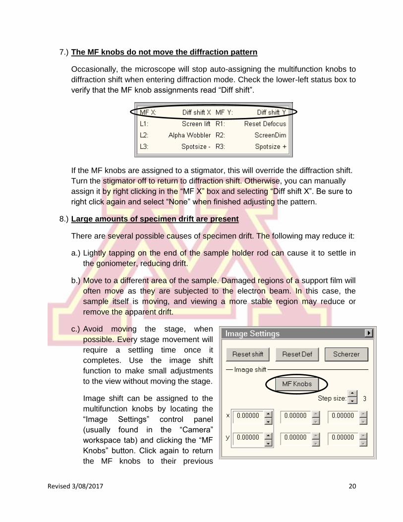
7.) The MF knobs do not move the diffraction pattern
Occasionally, the microscope will stop auto-assigning the multifunction knobs to
diffraction shift when entering diffraction mode. Check the lower-left status box to
verify that the MF knob assignments read “Diff shift”.
If the MF knobs are assigned to a stigmator, this will override the diffraction shift.
Turn the stigmator off to return to diffraction shift. Otherwise, you can manually
assign it by right clicking in the “MF X” box and selecting “Diff shift X”. Be sure to
right click again and select “None” when finished adjusting the pattern.
8.) Large amounts of specimen drift are present
There are several possible causes of specimen drift. The following may reduce it:
a.) Lightly tapping on the end of the sample holder rod can cause it to settle in
the goniometer, reducing drift.
b.) Move to a different area of the sample. Damaged regions of a support film will
often move as they are subjected to the electron beam. In this case, the
sample itself is moving, and viewing a more stable region may reduce or
remove the apparent drift.
c.) Avoid moving the stage, when
possible. Every stage movement will
require a settling time once it
completes. Use the image shift
function to make small adjustments
to the view without moving the stage.
Image shift can be assigned to the
multifunction knobs by locating the
“Image Settings” control panel
(usually found in the “Camera”
workspace tab) and clicking the “MF
Knobs” button. Click again to return
the MF knobs to their previous
Revised 3/08/2017 21
assignment. The image shift has three separate registers, like the stigmator
controls, which can be used to store different position offsets.
d.) Having the door open, talking, or large groups present in the instrument room
will inevitably produce thermal and acoustic variations that will result in
specimen drift. Avoid these situations whenever possible.
9.) Other problems
If the software is behaving unexpectedly, you may close and restart the user
interface and Digital Micrograph. Logging out and back in may also resolve some
problems. Do not restart the PC!

Revised 3/08/2017 22
IX. Addenda
Remote access to saved images
Saved images can be remotely accessed via SFTP. To connect to the file storage, you
must use an SFTP client such as WinSCP (Windows) or Fugu (Mac OSX).
The host name is rem30271.charfac.umn.edu, port 22. Be sure to select SFTP as the
protocol (regular FTP connections will not be allowed). The username and password to
login are the same as those used to save the files from the TEM computer.
TEM Discussion Lists
Signing up for the appropriate TEM mailing lists is strongly suggested. These lists will
be used to notify of instrument downtimes, changes in policy, and so forth.
The appropriate mailing list for each instrument is:
FEI T12, Shepherd: [email protected]
FEI FEGTEM, Shepherd (F30): [email protected]
FEI Cryo FEGTEM, NHH (NHH F30): [email protected]
Messages sent to the mail list will be distributed to everyone on the list. Some uses for
the mailing list include:
To subscribe/unsubscribe:
Email addresses at umn.edu can subscribe automatically through [email protected].
To subscribe non-umn.edu addresses, contact CharFac staff.
Subscribe: email [email protected] with no subject. In the body, type:
“SUBSCRIBE <list name> <your name>”
For example, to subscribe to the T12 list, I would send “SUBSCRIBE TEM-T12 Jason
Myers”. You will receive a confirmation email from the server.
Unsubscribe: email [email protected] with no subject. In the body type:
“SIGNOFF <list name>”
So to remove yourself from the T12 list, send “SIGNOFF TEM-T12”. You will receive a
confirmation email from the server.