techtip rocco-48 volt lestronic ii diagnostics
TRANSCRIPT

.
Diagnostics of: Lestronic II 48 Volt DC Battery Chargers Used in Z30DC Z34DC Z45DC and early Z40 Units
Tools needed: Voltmeter Screwdriver Jumper Wires w/clips Insulated Handle Pliers Optional: Oscilloscope

Tech Tips Safety Rules
Danger Failure to obey the instructions and safety rules in the appropriate Operator's Manual and Service Manual for your machine will result in death or serious injury. Many of the hazards identified in the operator’s manual are also safety hazards when maintenance and repair procedures are performed. Do Not Perform Maintenance Unless:
You are trained and qualified to perform maintenance on this machine. You read, understand and obey:
o manufacturer’s instructions and safety rules o employer’s safety rules and worksite regulations o applicable governmental regulations
You have the appropriate tools, lifting equipment and a suitable workshop. The information contained in this tech tip is a supplement to the service manual. Consult the appropriate service manual of your machine for safety rules and hazards.
Introduction
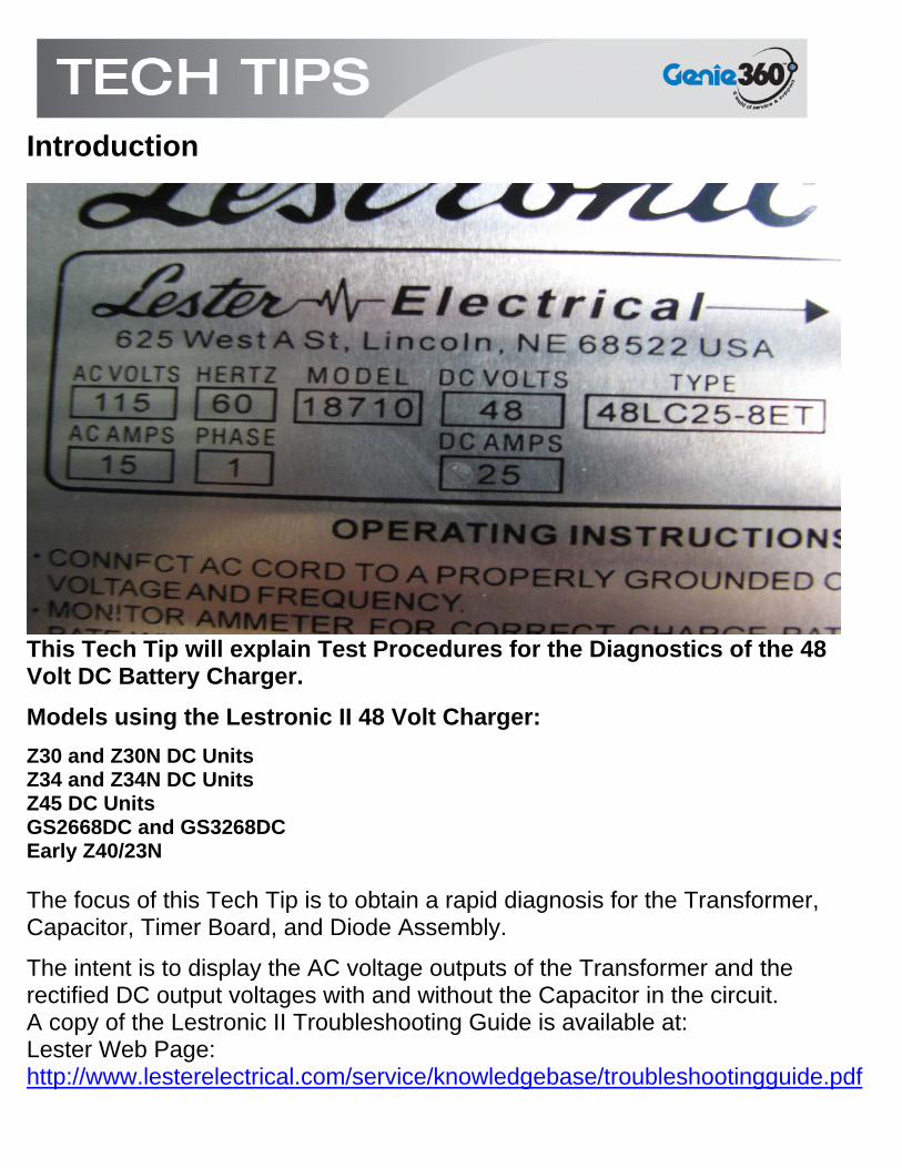
This Tech Tip will explain Test Procedures for the Diagnostics of the 48 Volt DC Battery Charger.
Models using the Lestronic II 48 Volt Charger:
Z30 and Z30N DC Units Z34 and Z34N DC Units Z45 DC Units GS2668DC and GS3268DC Early Z40/23N The focus of this Tech Tip is to obtain a rapid diagnosis for the Transformer, Capacitor, Timer Board, and Diode Assembly.
The intent is to display the AC voltage outputs of the Transformer and the rectified DC output voltages with and without the Capacitor in the circuit. A copy of the Lestronic II Troubleshooting Guide is available at: Lester Web Page: http://www.lesterelectrical.com/service/knowledgebase/troubleshootingguide.pdf

Safety and Familiarization Always practice SAFE work procedures when working with Batteries and Chargers. Batteries can EXPLODE and Chargers can ELECTROCUTE!
Read and Heed! Throughout this Tech Tip there will be warnings pointing out the hazards involved when diagnosing battery chargers. NEVER become complacent with your SAFETY or the SAFETY of others. Always consider all circuits LIVE until verified otherwise.

Become Familiar with the Battery Charger As simple as this photo may appear, there are many hazards present. Do NOT plug the charger in during this TECH TIP until instructed to do so.
Take the time to Locate and Identify all the Components inside the Battery Charger. Remove all the wire ties for easy access and safe diagnostics.
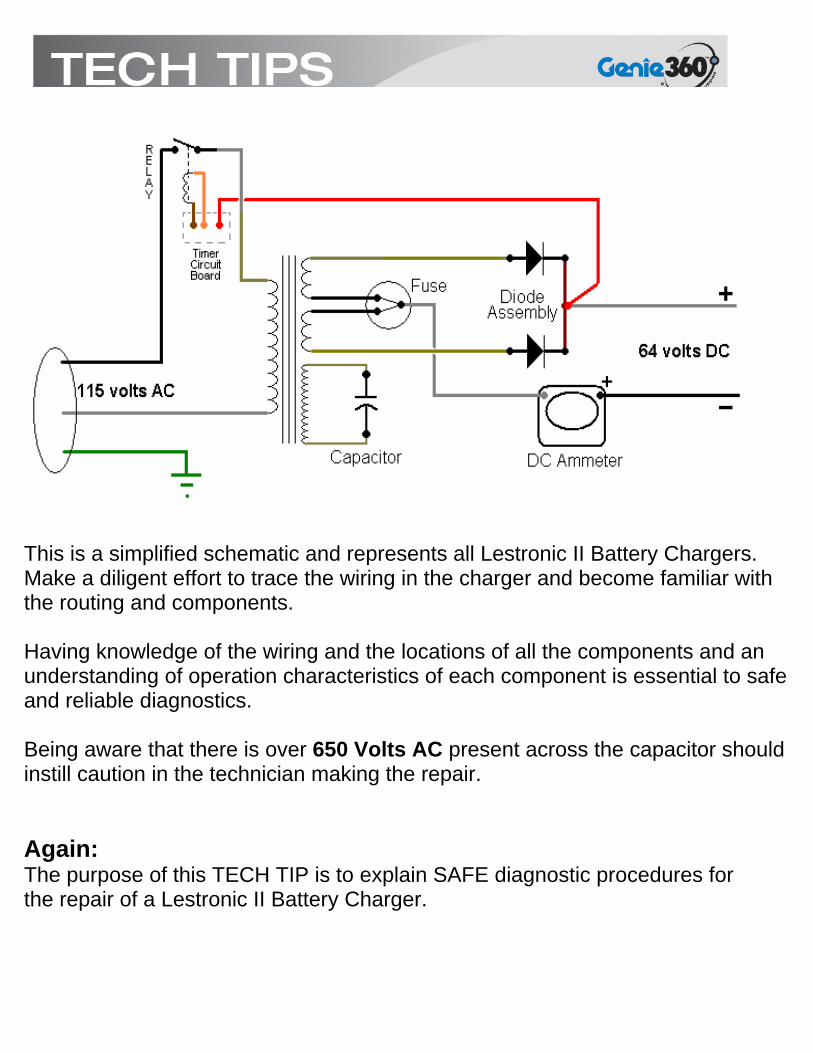
This is a simplified schematic and represents all Lestronic II Battery Chargers. Make a diligent effort to trace the wiring in the charger and become familiar with the routing and components. Having knowledge of the wiring and the locations of all the components and an understanding of operation characteristics of each component is essential to safe and reliable diagnostics. Being aware that there is over 650 Volts AC present across the capacitor should instill caution in the technician making the repair. Again: The purpose of this TECH TIP is to explain SAFE diagnostic procedures for the repair of a Lestronic II Battery Charger.

A Brief Explanation of the Functions of the Components:
When the AC Power Cord is plugged into a live receptacle and the DC Power Output is connected to a known good 48 volt DC set of batteries, the battery voltage will follow the RED wire from the DIODE ASSEMBLY to the ELECTRONIC TIMER CARD. If the battery voltage is at a sufficient level, the ELECTRONIC TIMER will then energize the RELAY on the TIMER CARD. Energizing the RELAY will close the Relay’s CONTACS and the AC HOT will be connected to the PRIMARY WINDINGS of the TRANSFORMER. The PRIMARY WINDINGS will then induce a voltage into the 3 SECONDARY WINDINGS. Two of the sets of SECONDARY WINDINGS drop the PRIMARY voltage from the 115 Volts AC to an appropriate voltage level as will be explained later. A third SECONDARY WINDING is connected to a CAPACITOR .

This charger is designed utilizing a coil on the transformer (the third SECONDARY WINDING) connected to a capacitor that is matched to oscillate at the charger’s rated AC line frequency, typically 50 or 60 hertz. The oscillating circuit produces a magnetic field that encompasses the transformer. This magnetic field provides regulation of the charger’s output when fluctuations in the AC line voltage occur.
The two low voltage SECONDARY WINDINGS have their voltage directed to the BATTERIES through the two DIODES when their potential is positive. When one TAN wire from the low voltage secondary is positive, the other TAN wire on the other low voltage secondary is negative. Each coil and diode set up a Half Wave Rectifier. The polarities of the low voltage secondarys reverse each time the AC signal reverses (50 or 60Hz). The two low voltage coils and their respective diodes work in tandem to provide Full Wave Rectification for rapid battery charging.
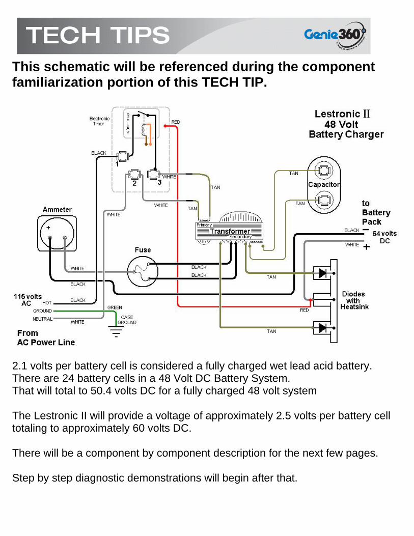
This schematic will be referenced during the component familiarization portion of this TECH TIP.
2.1 volts per battery cell is considered a fully charged wet lead acid battery. There are 24 battery cells in a 48 Volt DC Battery System. That will total to 50.4 volts DC for a fully charged 48 volt system The Lestronic II will provide a voltage of approximately 2.5 volts per battery cell totaling to approximately 60 volts DC. There will be a component by component description for the next few pages. Step by step diagnostic demonstrations will begin after that.
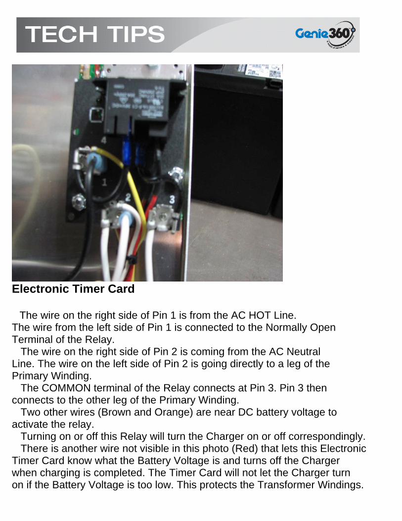
Electronic Timer Card The wire on the right side of Pin 1 is from the AC HOT Line. The wire from the left side of Pin 1 is connected to the Normally Open Terminal of the Relay. The wire on the right side of Pin 2 is coming from the AC Neutral Line. The wire on the left side of Pin 2 is going directly to a leg of the Primary Winding. The COMMON terminal of the Relay connects at Pin 3. Pin 3 then connects to the other leg of the Primary Winding. Two other wires (Brown and Orange) are near DC battery voltage to activate the relay. Turning on or off this Relay will turn the Charger on or off correspondingly. There is another wire not visible in this photo (Red) that lets this Electronic Timer Card know what the Battery Voltage is and turns off the Charger when charging is completed. The Timer Card will not let the Charger turn on if the Battery Voltage is too low. This protects the Transformer Windings.

the Diode Assembly The Diodes Rectify (change) the AC voltage coming in on the large TAN wires to DC voltage out to the right side of the two Diodes on the Copper Plate. The connection at the center of the Copper Plate is connected through the WHITE Wire to the Battery Plus Terminal at the Battery Pack.
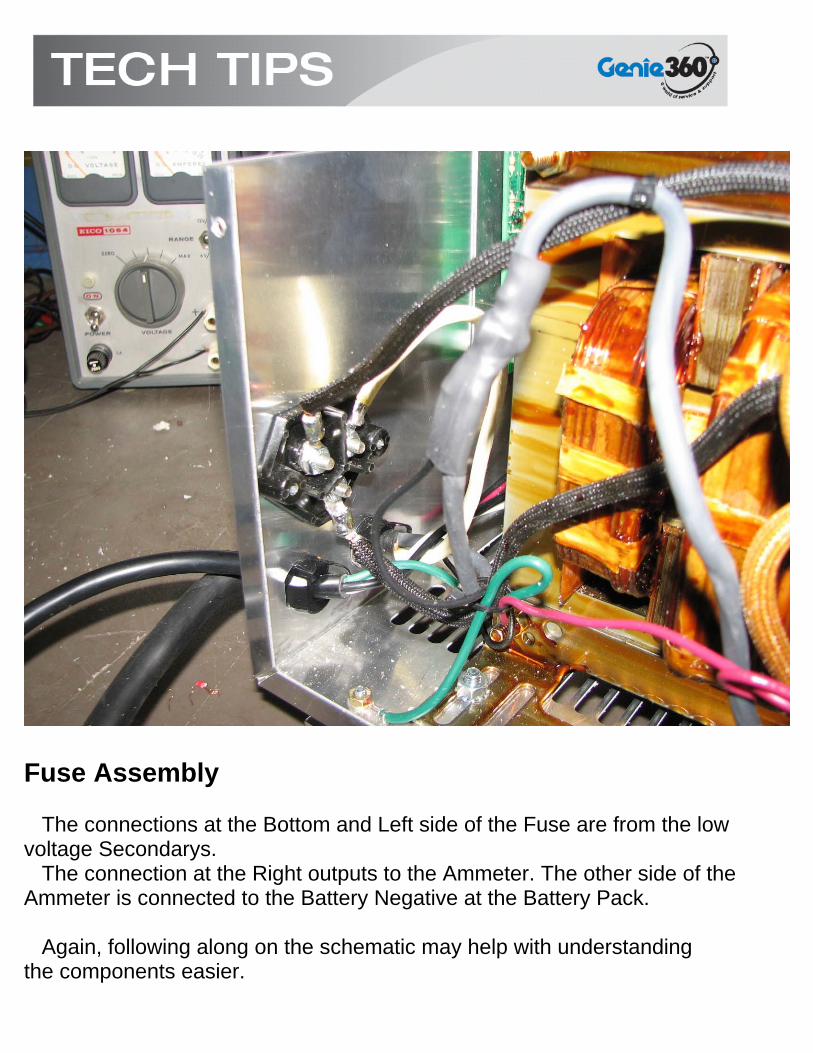
Fuse Assembly The connections at the Bottom and Left side of the Fuse are from the low voltage Secondarys. The connection at the Right outputs to the Ammeter. The other side of the Ammeter is connected to the Battery Negative at the Battery Pack. Again, following along on the schematic may help with understanding the components easier.

This shows a view of the Primary Windings. They are the only two wires on this side of the Transformer. This sets up the Magnetic Field which will induce voltages into the Secondarys. There are soldered joints where the White wires meet the Tan wires. This is a place to check if the charger does not turn on but the Relay energized.

These are the Secondary Windings They provide the Voltage to the Diodes for Rectification and also to the Capacitor for the Ferro-Resonant characteristic. Ferro-Resonant characteristic: The output charge current starts at a high value and tapers to a low value. As the batteries become charged and increase in voltage the output current is reduced as it approaches the end of the charge cycle. This type of charger is designed for use with deep cycle flooded wet lead-acid batteries only and will over-charge sealed lead acid/gel types of batteries.

The Capacitor and the Diode Assembly
Note the Stripe on the Diode. This is the Cathode Marking. If the charger is used continuously because of weak batteries or bad cells in a battery, the current will remain high causing excessive heating at the Diode/Copper Plate junction. This has the tendency to de-solder the joint. Check here if there is no DC conversion from the Diodes.
Beware of the connectors at the top of the Capacitor!!!! There will be 650 to 700 Volts AC present when the Charger is turned on and charging.
DIAGNOSTICS
CAUTION: We will be diagnosing LIVE Electronic Components! Exercise ALL due Caution and Stay Aware! Assumptions: 1) The Charger has been removed from the machine it was installed in. 2) A 48 Volt Battery Pack is available but NOT connected to the Charger. 3) 110 to 120 Volts AC 60Hz is available but NOT connected to the Charger. 4) All wiring at facility is to Code and all Drop Cords and Wall Outlets are in good SAFE condition. Circuit Breakers and G.F.I. devices functional. 5) All appropriate Safety Gear and Systems are in place. 6) the technician performing these tasks will read and understand ALL Instructions

Transformer Test:
AC Line Voltage NOT Connected DC Battery Pack NOT Connected The Charger’s Ammeter is connected to its circuit Because the Charger is equipped with a Low Voltage Cut-Out it will be Necessary to Bypass the Electronic Timer Card and the Relay.
This can be accomplished one of two ways:
1) By Jumping a wire from Pin 1 to Pin 3 This in effect bypasses the Relay.

2) By simply removing the wire from Pin 1 and connecting it to Pin 3. Pin 1 remember, is coming from the AC Line Power HOT.
Bypassing the relay in this manner will let the Charger start when the power cord is plugged in. Do not plug the Charger in at this time.

Disconnect the Terminals at the Capacitor and The Diodes: Insulate Capacitor Lead Connectors for SAFETY purposes
Use Insulated Pliers to remove the connectors at the Capacitor. Capacitors can store a charge for an extended period of time. Caution should be taken when working on or around Capacitors. Portions of the diagnostics will have the Capacitor connected or disconnected. For now, the Capacitor will be disconnected.

AC Line Voltage AC Voltmeter Plug the Charger into a known working wall receptacle or extension cord providing 110 to 120 Volts AC. The test leads from the Voltmeter are across the Neutral and Hot wires located on the Electronic Timer Card. The Hot wire has been removed from Terminal 1 and installed on Terminal 3 to bypass the Relay The Voltmeter will display the voltage being applied to the Primary Windings

Next: Capacitor and Batteries Disconnected AC Voltmeter Connect the Voltmeter leads to the Charger Negative (here shown at the Fuse) and the Coil Lead from the Secondary Winding as shown in this photo. For the sake of this discussion we will label this lead Coil #1. This is the stepped-down AC voltage of the Secondary. Depending on the Actual Line Voltage applied to the Charger Plug, this reading will be close to that shown in the photo. If the Line Voltage is lower than the 119.8 this demonstration was using, this value will be lower. A higher Line Voltage applied to the plug will result in a higher voltage here.

Capacitor and Batteries Disconnected AC Voltmeter Connect the Voltmeter leads to the Charger Negative (here shown at the Fuse) and the Coil Lead from the Secondary Winding as shown in this photo. For the sake of this discussion we will label this lead Coil #2. This is the stepped-down AC voltage of the Secondary. Depending on the Actual Line Voltage applied to the Charger Plug, this reading will be close to that shown in the photo. If the Line Voltage is lower than the 119.8 this demonstration was using, this value will be lower. A higher Line Voltage applied to the plug will result in a higher voltage here. The voltages at Coils 1 and 2 must be close to one another.

Capacitor and Batteries Disconnected AC Voltmeter The Voltmeter is shown here connected across both leads of the Secondary. The Voltage displayed must be close to the added total of the individual Coils 1 and 2. if they are not close, the connection at the Fuse will be suspect. Following along with the schematic will help clarify this demonstration. If the results of these tests are as demonstrated here, the Transformer is in Good Condition.

Capacitor and Batteries Disconnected AC Voltmeter Measuring across the Secondary Winding Leads at the Capacitor will display a Voltage near 450 Volts AC. Be Careful. If this value is lower than 400 volts AC there are shorted windings in the Secondary Winding. A Zero volt reading will signify an open winding.

Unplug the Battery Charger from the AC Power Line
Connect Capacitor, Leave Batteries Disconnected. AC Voltmeter Carefully connect the Secondary Coil Windings to the Capacitor using Insulated Handle Pliers.
Plug the Charger into the AC Power Line
Place the Voltmeter across the Terminals on the Capacitor. The result should be close to a 50 % increase over the 450 Volts AC
If the voltage does not increase it is an indication that the Capacitor is defective and needs replacing.

Capacitor Connected, Batteries Disconnected. AC Voltmeter The Voltmeter is connected from the Charger Negative at the Fuse and to Coil # 1. It is displaying the Peak AC Voltage of the Secondary Windings. This is because the Capacitor is in effect filtering the output of the secondary. If the capacitor was disconnected, the voltage displayed would drop down to the 40.51 volts seen earlier. If the voltage did not increase from the voltage with the capacitor disconnected, the capacitor or its connections are suspect.

Capacitor Connected, Batteries Disconnected. AC Voltmeter The Voltmeter is connected from the Charger Negative at the Fuse and to Coil # 2. It is displaying the Peak AC Voltage of the Secondary Windings. This is because the Capacitor is in effect filtering the output of the secondary. If the capacitor was disconnected, the voltage displayed would drop down to the 40.51 volts seen earlier. If the voltage did not increase from the voltage with the capacitor disconnected, the capacitor or its connections are suspect.

Capacitor Connected, Batteries Disconnected. AC Voltmeter The Voltmeter is shown here connected across both leads of the Secondary. The Voltage displayed must be close to the added total of the individual Coils 1 and 2. if the reading is not close, the connection at the Fuse will be suspect. Following along with the schematic will help clarify this demonstration. If the results of these tests are as demonstrated here, the Transformer and the Capacitor are in Good Condition.
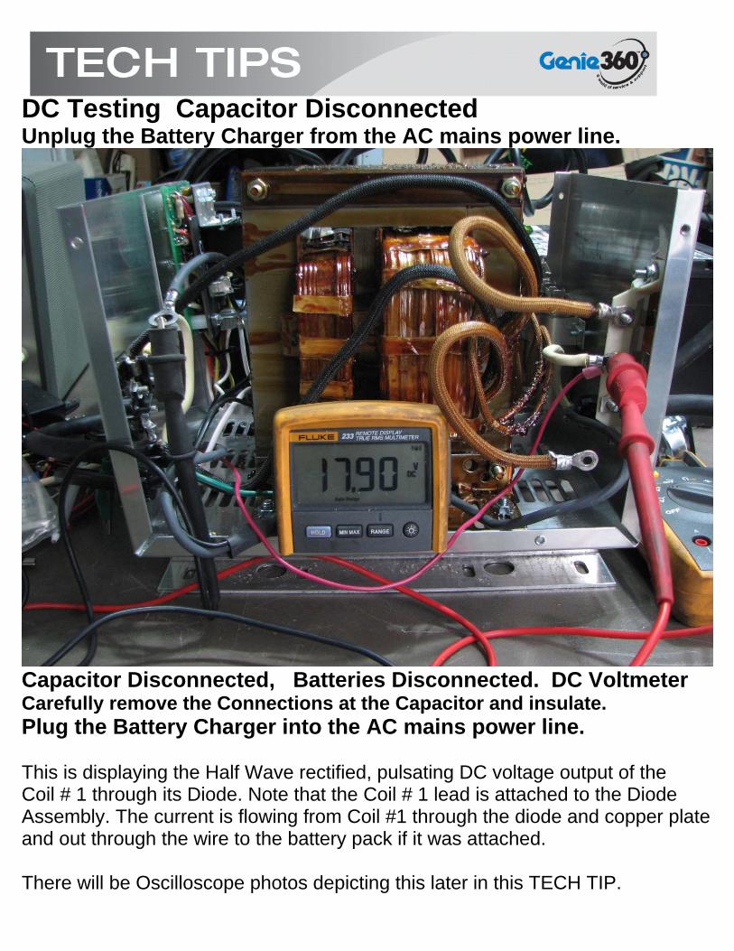
DC Testing Capacitor Disconnected Unplug the Battery Charger from the AC mains power line.
Capacitor Disconnected, Batteries Disconnected. DC Voltmeter Carefully remove the Connections at the Capacitor and insulate. Plug the Battery Charger into the AC mains power line. This is displaying the Half Wave rectified, pulsating DC voltage output of the Coil # 1 through its Diode. Note that the Coil # 1 lead is attached to the Diode Assembly. The current is flowing from Coil #1 through the diode and copper plate and out through the wire to the battery pack if it was attached. There will be Oscilloscope photos depicting this later in this TECH TIP.
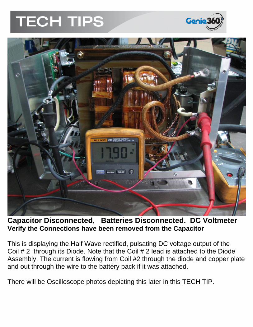
Capacitor Disconnected, Batteries Disconnected. DC Voltmeter Verify the Connections have been removed from the Capacitor This is displaying the Half Wave rectified, pulsating DC voltage output of the Coil # 2 through its Diode. Note that the Coil # 2 lead is attached to the Diode Assembly. The current is flowing from Coil #2 through the diode and copper plate and out through the wire to the battery pack if it was attached. There will be Oscilloscope photos depicting this later in this TECH TIP.

Capacitor Disconnected, Batteries Disconnected. DC Voltmeter Verify the Connections have been removed from the Capacitor This will be the combined Half Wave rectified, pulsating DC voltages from Coils 1 and 2. This is considered Full Wave Rectification. This voltage will obviously be too low to charge a 48 volt DC Battery System. This is the important part the Capacitor and Batteries play in the overall performance of this type of Battery Charger.

Top photo shows AC pattern at output of upper Secondary Coil Coil #1
The scope is displaying a value of approximately 60 AC Volts Peak. The voltmeter in previous photos is displaying the 40.5 volt RMS values.

This photo shows AC pattern at output of lower Secondary Coil Coil #2 Note the Capacitor and Secondary Windings are NOT connected The voltmeter displayed the RMS value of the signal. It was at 40.5 volts AC in an earlier photo. This is equivalent to the useable voltage of the 60 volts peak that is being outputted. This is because the voltmeter is taking into consideration the times the voltage is in between the peaks and not at the 60 volts level. The screen is showing the signal going from Zero volts up to approximately +60 volts, back to Zero volts, then to -60 volts and back up to Zero volts. This is considered One Cycle or One Hertz. 1 cps or 1Hz. The screen is showing 3 complete cycles. This cycling happens 60 times per Second in the United States and other parts of the world. Some countries use 50Hz as their power distribution frequency.

Half Wave Rectification with only Coil 1 attached to Diodes Capacitor NOT Connected This shows the result of the AC signal processed through a diode. Note that Coil #1 is connected to the Diode Assembly and Coil #2 is disconnected. The diode is only permitting the Positive portion of the signal to pass. This is what a diode does.

Half Wave Rectification with only Coil 2 attached to Diodes Capacitor NOT Connected This shows the result of the AC signal processed through a diode. Note that Coil #2 is connected to the Diode Assembly and Coil #1 is disconnected. The diode is only permitting the Positive portion of the signal to pass.

Full Wave Rectification with AC Signal being fed through both 1 and 2 Coils Capacitor NOT Connected This shows the result of the AC signal processed through both diodes.
Note that Coil #1 and Coil #2 are connected to the Diode Assembly.
The diodes are permitting both Positive portions of the signal to pass through to the Copper Plate and then to the Battery Pack if it was attached. It will need further filtering by the Capacitor and Batteries before it becomes an efficient Battery Charger. This will be demonstrated soon. .
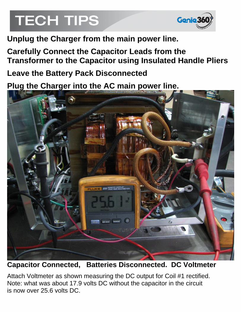
Unplug the Charger from the main power line.
Carefully Connect the Capacitor Leads from the Transformer to the Capacitor using Insulated Handle Pliers
Leave the Battery Pack Disconnected
Plug the Charger into the AC main power line.
Capacitor Connected, Batteries Disconnected. DC Voltmeter
Attach Voltmeter as shown measuring the DC output for Coil #1 rectified. Note: what was about 17.9 volts DC without the capacitor in the circuit is now over 25.6 volts DC.

Capacitor Connected, Batteries Disconnected. DC Voltmeter
Attach Voltmeter as shown measuring the DC output for Coil #2 rectified. Note: what was about 17.9 volts DC without the capacitor in the circuit is now over 25.9 volts DC. The voltages of Coils 1 and 2 should be close to each other but need not be exact.

Capacitor Connected, Batteries Disconnected. DC Voltmeter
Both Coils are attached to the Diode Assembly
The Voltmeter is connected to the Charger Negative and the Positive Output of the Diode Assembly.
The Voltmeter is displaying the Full Wave rectified voltage with some filtration provided by the capacitance added to the circuit. Further Filtration will be provided by the batteries.
The 50 volts shown here is too low to charge a 48 volt DC system. 2.5 volts per battery cell is desired. A 48 volt battery pack has a total of 24 cells. This would require a voltage of approximately 62.5 Volts DC.

Unplug the AC Line Cord of the Charger from the AC power mains.
Connect the Battery Charger to a 48 Volt Battery Pack This could be the batteries of the machine the Charger came from or for testing purposes only a set of batteries as pictured below.
These are Lawn and Garden Tractor batteries. They are 12 volts each wired together in series to total 48 volts. These batteries will be adequate for testing purposes only.

Plug the AC Line Cord of the Charger into the AC Power Mains
Capacitor Connected, Batteries Connected, Secondary Connected to Diode Assembly, AC Power Cord Plugged In DC Voltmeter
Attach DC Voltmeter across Charger Output. This photo shows the Voltage of the Charger connected to fully charged batteries. A load meter or other method of discharging the batteries may be used to reduce battery voltage for additional testing The Oscilloscope is displaying the filtered DC value of over 62 Volts DC. The straight line on the scope shows the pulsating DC has been filtered by the Batteries and Capacitor.
If all these tests have results reflective of those shown here then the Transformer, Capacitor, and Diode Assembly can be considered good. Remove the Jumper or Jumped Wire at the Electronic Timer Card that was temporarily used during troubleshooting before placing Charger back into service. If the charger will not come on when plugged in, the problem may be in the Timer Card, Relay or the Power Cord. For further testing, Consult the Lestronic II Troubleshooting Guide available from Genie Service Department or from Lester Electrical. Lester Web Page: http://www.lesterelectrical.com/service/knowledgebase/troubleshootingguide.pdf If there are further questions pertaining to this TECH TIP or Battery Chargers in general, please contact the GENIE/TEREX Service Department. 800-536-1800