technology roadmap energy storage · pdf filetechnology roadmap energy storage table of...
TRANSCRIPT

2035 2040
2045
2050
Technology RoadmapEnergy storage
En
erg y Technolog y Perspecti
ves

INTERNATIONAL ENERGY AGENCY
The International Energy Agency (IEA), an autonomous agency, was established in November 1974. Its primary mandate was – and is – two-fold: to promote energy security amongst its member
countries through collective response to physical disruptions in oil supply, and provide authoritative research and analysis on ways to ensure reliable, affordable and clean energy for its 28 member countries and beyond. The IEA carries out a comprehensive programme of energy co-operation among its member countries, each of which is obliged to hold oil stocks equivalent to 90 days of its net imports. The Agency’s aims include the following objectives:
n Secure member countries’ access to reliable and ample supplies of all forms of energy; in particular, through maintaining effective emergency response capabilities in case of oil supply disruptions.
n Promote sustainable energy policies that spur economic growth and environmental protection in a global context – particularly in terms of reducing greenhouse-gas emissions that contribute to climate change.
n Improve transparency of international markets through collection and analysis of energy data.
n Support global collaboration on energy technology to secure future energy supplies and mitigate their environmental impact, including through improved energy
efficiency and development and deployment of low-carbon technologies.
n Find solutions to global energy challenges through engagement and dialogue with non-member countries, industry, international
organisations and other stakeholders.IEA member countries:
Australia Austria
Belgium Canada
Czech RepublicDenmark
Finland France
GermanyGreece
HungaryIreland
ItalyJapan
Korea (Republic of)LuxembourgNetherlandsNew Zealand NorwayPolandPortugalSlovak RepublicSpainSwedenSwitzerland
TurkeyUnited Kingdom
United States
The European Commission also participates in
the work of the IEA.
© OECD/IEA, 2014International Energy Agency
9 rue de la Fédération 75739 Paris Cedex 15, France
www.iea.org
Secure Sustainable Together
Please note that this publication is subject to specific restrictions that limit its use and distribution.
The terms and conditions are available online at http://www.iea.org/termsandconditionsuseandcopyright/
40Years_Page02_2014_A4_Q.indd 1 12/02/2014 12:34:20
© O
EC
D/IE
A, 2
014

1Foreword
Current trends in energy supply and use are patently unsustainable – economically, environmentally and socially. Without decisive action, energy-related emissions of carbon dioxide (CO2) will more than double by 2050 and increased fossil energy demand will heighten concerns over the security of supplies. We can and must change our current path, but this will take an energy revolution; and low-carbon energy technologies will have a crucial role to play. Energy efficiency, many types of renewable energy, carbon capture and storage (CCS), nuclear power and new transport technologies will all require widespread deployment if we are to sharply reduce greenhouse gas (GHG) emissions. Every major country and sector of the economy must be involved. The task is urgent if we are to make sure that investment decisions taken now do not saddle us with sub-optimal technologies in the long term.
Awareness is growing on the need to turn political statements and analytical work into concrete action. To spark this movement, at the request of the G8 nations, the International Energy Agency (IEA) is leading the development of a series of roadmaps for some of the most important technologies. By identifying the steps needed to accelerate the implementation of radical technology changes, these roadmaps will enable governments, industry and financial partners to make the right choices – and in turn help societies to make the right decisions.
Energy storage technologies can support energy security and climate change goals by providing valuable services in developed and developing energy systems. A systems approach to energy system design will lead to more integrated
and optimised energy systems. Energy storage technologies can help to better integrate our electricity and heat systems and can play a crucial role in energy system decarbonisation by:
z improving energy system resource use efficiency
z helping to integrate higher levels of variable renewable resources and end-use sector electrification
z supporting greater production of energy where it is consumed
z increasing energy access
z improving electricity grid stability, flexibility, reliability and resilience.
While some energy storage technologies are mature or near maturity, most are still in the early stages of development and currently struggle to compete with other non-storage technologies due to high costs. They will require additional attention before their potential can be fully realised. Governments can help accelerate the development and deployment of energy storage technologies by supporting targeted demonstration projects for promising storage technologies and by eliminating price distortions that prevent storage technologies from being compensated for the suite of services they provide. Energy storage technologies have the potential to support our energy system’s evolution, but realising this potential will require government, industry, academia and financial stakeholders to work together to help overcome existing barriers.
This publication is produced under my authority as Executive Director of the IEA.
Maria van der HoevenExecutive Director
International Energy Agency
Foreword
This publication reflects the views of the International Energy Agency (IEA) Secretariat but does not necessarily reflect those of individual IEA member countries. The IEA makes no representation or warranty, express or implied, in respect to the publication’s contents (including its completeness or accuracy) and shall not be responsible for any use of, or reliance on, the publication.
© O
EC
D/IE
A, 2
014
2 Technology Roadmap Energy Storage
Table of contentsForeword 1
Acknowledgements 4
Key findings and actions 5
Key findings 5
Key actions for the next ten years 5
Introduction 6
Rationale for energy storage 6
Purpose, process, and structure of the roadmap 7
Roadmap scope 7
Energy storage applications 9
Key application definitions 10
Benefits-stacking 12
Locations 15
Status of energy storage technologies today 16
Current installed capacity 16
Electricity storage 21
Thermal storage 22
Vision for deployment to 2050 26
The ETP 2014 scenarios for a clean energy transition 26
Three scenarios for electricity storage deployment 28
Regional factors for energy storage deployment 30
Energy storage technology development: actions and milestones 38
Actions spanning across technologies and applications 38
Short-term (seconds-minutes) storage applications for reserve services and frequency regulation 40
Distributed battery storage for renewables integration, frequency regulation 40
Long-term (hours-seasons) storage applications for arbitrage, load following, and other grid services 42
Thermal energy storage for low temperature (<10°C) applications 43
Thermal energy storage for medium temperature (10°C to 250°C) applications 44
Thermal energy storage for high temperature (>250°C) applications 45
Policy, finance, and international collaboration: actions and milestones 46
Policy and regulatory frameworks 49
Incentivising investment 50
Planning and permitting 50
Training and public engagement 51
International collaboration 52
Conclusion: near-term actions for stakeholders 53
Annexes 55
Acronyms, abbreviations and units of measure 56
References 57
© O
EC
D/IE
A, 2
014
3Table of contents
List of figures
Figure 1. Power requirement versus discharge duration for some applications in today’s energy system 14
Figure 2. Hypothetical deployment of storage assets across an electric power system 15
Figure 3. Maturity of energy storage technologies 16
Figure 4. Current global installed grid-connected electricity storage capacity (MW) 17
Figure 5. Stylised French load curves (cold weekday in winter) 25
Figure 6. Share of electricity generated from variable renewables (%) by region in the 2DS 27
Figure 7. Electricity storage capacity for daily electricity storage by region in 2011 and 2050 for ETP 2014 scenarios 28
Figure 8. LCOE in the "breakthrough" scenario in 2013 and 2050 29
Figure 9. Investment needs for energy storage in different scenarios, 2010 to 2050 29
Figure 10. Land and water footprint for electricity storage and generation technologies 30
Figure 11. Generation mix in 2050 in the United States for the range of scenarios (low-demand) 31
Figure 12. Installed capacity in 2050 as renewable electricity levels increase (low-demand scenario) 32
Figure 13. Installed capacity and electricity generation in Germany: 1995, 2011, 2030, and 2050 33
Figure 14. Challenges faced by the electricity sector in Germany 34
Figure 15. Future electricity grid configuration in China 36
List of tables
Table 1. Workshop contributions to the energy storage roadmap 7
Table 2. Key characteristics of storage systems for particular applications in the energy system 9
Table 3. Energy storage technologies and intended applications in United States PJM market 13
Table 4. Near-term suitability criteria for determining prime energy storage technologies for deployment 14
Table 5. Estimated thermal energy storage capacity in the United States in 2011 17
Table 6. Energy storage technologies: current status and typical locations in today’s energy system 18
Table 7. Electric water heating: residential consumption 29
Table 8. Options for various energy system applications in Germany 35
Table 9. Examples of government actions that have positively supported energy storage technology deployment 47
List of boxes
Box 1. Energy versus power applications for electricity storage technologies 10
Box 2. Potential use of thermal storage in CHP plants to support the integration of renewable energy resources 11
Box 3. The impacts of US Federal Energy Regulatory Commission Orders 755 (2011) and 784 (2013) on energy storage deployment 12
Box 4. Energy storage technology descriptions 20
Box 5. Sodium-sulphur battery for transmission infrastructure deferral and voltage regulation in the United States 22
Box 6. Increasing system efficiency via waste heat utilisation 23
Box 7. Peak demand reduction using residential hot water heaters in France 24
Box 8. Energy Technology Perspectives 2DS 27
Box 9. A vision for electricity storage in a high renewable electricity future in the United States 31
Box 10. Energy storage to support energy efficiency and renewables in Germany 33
Box 11. Energy storage to support variable renewable energy resources in China 36
Box 12. Rare earth elements 41
© O
EC
D/IE
A, 2
014

4 Technology Roadmap Energy storage
Imre Gyuk (US DOE); Rao Konidena and Scott Baker (GO15); Gunter Siddiqi (Bundesamt für Energie); Anthony Vassallo (The University of Sydney); Yo Mishima, Eiko Nakayama, Tutsuya Tomida, Tatsuya Miyazaki, and Kelichi Onozawa (METI); Per-Olof Granstrom and Joris Knigge (EDSO).
Finally, the IEA would like to thank the numerous experts who provided the authors with information and/or comments on drafts of the roadmap and Technology Annex: Jianhua Bai, Mark Barrett, Brahim Betraoui, Luisa F. Cabeza, John Cheng, Benoit Decourt, Paul Denholm, Paul Dodds, Jean-Michel Durand, Robert Fares, Jared Garrison, Marco Gazzino, Frederik Geth, Logan Goldie-Scot, Naoki Hara, Jennifer Hiscock, Arne Höll, Mark Howells, Andreas Hauer, Sylvain Hercberg, Magnus Hindsberger, Takao Ikeda, Jens Kühne, Chuck Levitan, Francis Li, Liam Lidstone, Jun Liu, Vincent Mazauric, Stephen Orita, Anthony Price, Peter Schossig, Yoshiaki Shibata, Axel Strang, Peter Taylor, Yuriko Terao, Manuel Welsch, Mike Wilks, Kendra Wong, Hendrik Wust, Shicong Zhang and Andreas Zucker. The IEA would like to acknowledge the large number of participants and contributions made by attendees of the three workshops held at the IEA who are too numerous to be named individually.
The authors would also like to thank Kristine Douaud for editing the manuscript a well as the IEA publication unit, in particular Muriel Custodio, Astrid Dumond, Rebecca Gaghen, Cheryl Haines and Bertrand Sadin for their assistance in layout and graphical design support.
For more information on this document, contact:[email protected]
The International Energy Agency’s Energy Technology Policy Division prepared this publication. Melissa C. Lott is the primary author of this roadmap together with contributions from Sang-Il Kim. Cecilia Tam, co-ordinator of the Energy Technology Roadmaps programme, was responsible for the development of this roadmap and provided valuable leadership throughout. Didier Houssin, Director of the Directorate of Sustainable Energy Policy and Technology and Jean-François Gagné, Head of the Energy Technology Policy Division, provided important guidance and input. David Elzinga, Steve Heinen, Luis Munuera and Uwe Remme provided significant input and support.
Many other IEA colleagues provided thoughtful comments and support including Marco Baroni, Doug Cooke, Alex Körner, Simone Landolina, Simon Müller, Edoardo Patriarca, Cédric Philibert, Alvaro Portellano, Yuan Qin, Katrin Schaber, Tali Trigg, Laszlo Varro and Dennis Volk. Hanneke van Kleeff and Katerina Rus helped to prepare the manuscript.
This work was developed in collaboration with governments, industry, experts, and the IEA energy technology network. The roadmap was supported by the Japanese Ministry of Economy, Trade, and Industry (METI), Korea Power Exchange (KPX), US Department of Energy (US DOE), GO15 – Reliable and Sustainable Power Grids, and the Implementing Agreement for a Programme of Research and Development on Energy Conservation through Energy Storage (ECES IA).
The volunteers of the energy storage roadmap steering committee have provided guidance over the course of its development: Halime Ö. Paksoy and Christian Doetsch (ECES IA); Yeoungjin Chae (KPX);
Acknowledgements
© O
EC
D/IE
A, 2
014

5Key findings and actions
Key findings z Energy storage technologies include a large set
of centralised and distributed designs that are capable of supplying an array of services to the energy system. Storage is one of a number of key technologies that can support decarbonisation.
z Energy storage technologies are valuable in most energy systems, with or without high levels of variable renewable generation. Today, some smaller-scale systems are cost competitive or nearly competitive in remote community and off-grid applications. Large-scale thermal storage technologies are competitive for meeting heating and cooling demand in many regions.
z Individual storage technologies often have the ability to supply multiple energy and power services. The optimal role for energy storage varies depending on the current energy system landscape and future developments particular to each region.
z To support electricity sector decarbonisation in the ETP 2014 2DS, an estimated 310 GW of additional grid-connected electricity storage capacity would be needed in the United States, Europe, China and India. Significant thermal energy storage and off-grid electricity storage potential also exists. Additional data are required to provide a more comprehensive assessment and should be prioritised at the national level.
z Market design is key to accelerating deployment. Current policy environments and market conditions often cloud the cost of energy services, creating significant price distortions and resulting in markets that are ill-equipped to compensate energy storage technologies for the suite of services that they can provide.
z Public investment in energy storage research and development has led to significant cost reductions. However, additional efforts (e.g. targeted research and development investments and demonstration projects) are needed to further decrease energy storage costs and accelerate development.
z Thermal energy storage systems appear well-positioned to reduce the amount of heat that is currently wasted in the energy system. This waste heat is an underutilised resource, in part because the quantity and quality of both heat resources and demand is not fully known.
Key findings and actions
Key actions for the next ten years
z Determine where near-term cost effective niche markets exist and support deployment in these areas, sharing lessons learned to support long term development.
z Incentivise the retrofit of existing storage facilities to improve efficiency and flexibility.
z Develop marketplaces and regulatory environments that enable accelerated deployment, in part through eliminating price distortions and enabling benefits-stacking for energy storage systems, allowing these technologies to be compensated for providing multiple services over their lifetime.
z Support targeted demonstration projects for more mature, but not yet widely deployed, energy storage technologies to document system performance and safety ratings. Share information collected including lessons learned widely through storage stakeholder groups.
z Support investments in research and development for early stage energy storage technologies including technology breakthroughs in high-temperature thermal storage systems and scalable battery technologies, and systems that incorporate the use of both electricity and thermal energy storage (i.e. hybrid systems) to maximise resource use efficiency.
z Establish a comprehensive set of international standards in a manner that allows for incremental revisions as energy storage technologies mature.
z Evaluate and broadly disseminate the learning and experience from established installations. Information should include data on both technical aspects (e.g. generation, cost, performance) and contextual details (e.g. market conditions, energy pricing structures) specific to a region/market.
z Establish international and national data co-operation to foster research, monitor progress and assess the research and development (R&D) bottlenecks. Complete analysis in support of regional assessments to quantify the value of energy storage in specific regions and energy markets, and promote the development and adoption of tools devoted to evaluating energy storage project proposals.
© O
EC
D/IE
A, 2
014

6 Technology Roadmap Energy storage
IntroductionEnergy storage technologies absorb energy and store it for a period of time before releasing it to supply energy or power services. Through this process, storage technologies can bridge temporal and (when coupled with other energy infrastructure components) geographical gaps between energy supply and demand. Energy storage technologies can be implemented on large and small scales in distributed and centralised manners throughout the energy system. While some technologies are mature or near maturity, most are still in the early stages of development and will require additional attention before their potential can be fully realised.
In this roadmap, energy storage technologies are categorised by output: electricity and thermal (heat or cold).1 Technologies in both categories can serve as generators and consumers, giving them the potential to link currently disconnected energy markets (e.g. power, transportation fuels, and local heat markets). Broadly speaking, energy storage is a system integration technology that allows for the improved management of energy supply and demand. In many cases, a single unit of energy storage infrastructure can provide multiple valuable energy and power services.
This roadmap aims to increase understanding among a range of stakeholders of the applications that electricity and thermal energy storage technologies can be used for at different locations in the energy system.2 Emphasis is placed on storage technologies that are connected to a larger energy system (e.g. electricity grid), while a smaller portion of the discussion focuses on off-grid storage applications. This focus is complemented by a discussion of the existing technology, policy, and economic barriers that hinder energy storage deployment. Specific actions that can be taken to remove these obstacles are identified for key energy system stakeholder groups.
Rationale for energy storage Energy storage technologies are valuable components in most energy systems and could be an important tool in achieving a low-carbon future. These technologies allow for the decoupling of energy supply and demand, in essence providing a valuable resource to system operators. There are many cases where energy storage deployment is
1. Chemical (hydrogen) storage and fuel cell technologies are not included.
2. “Locations” refers to the supply, transmission and distribution, and demand portions of the energy system.
competitive or near-competitive in today’s energy system. However, regulatory and market conditions are frequently ill-equipped to compensate storage for the suite of services that it can provide. Furthermore, some technologies are still too expensive relative to other competing technologies (e.g. flexible generation and new transmission lines in electricity systems).
Historically, storage technologies were predominantly installed as an investment that could take advantage of dispatchable supply resources and variable demand. Today, increasing emphasis on energy system decarbonisation has drawn awareness to the ability for storage technologies to increase resource use efficiency (e.g. using waste heat through thermal storage technologies) and to support increasing use of variable renewable energy supply resources. Moving forward, it is important that energy storage be considered from a systems point of view with a focus on the multiple services that it can provide in bulk, small-scale (e.g. off-grid) and other applications.
R&D work is currently underway with the primary goals of realising technology cost reductions and improving the performance of existing, new and emerging storage technologies. Furthermore, many government and industry stakeholders are identifying and attempting to address non-technical barriers to deployment. Looking forward, the most important drivers for increasing use of energy storage will be:
z improving energy system resource use efficiency
z increasing use of variable renewable resources
z rising self-consumption and self-production of energy (electricity, heat/cold)
z increasing energy access (e.g. via off-grid electrification using solar photovoltaic (PV) technologies)
z growing emphasis on electricity grid stability, reliability and resilience
z increasing end-use sector electrification (e.g. electrification of transport sector).
© O
EC
D/IE
A, 2
014

7Introduction
Purpose, process and structure of the roadmapThis energy storage roadmap aims to:
z increase understanding among a range of stakeholders of the applications that electricity and thermal energy storage technologies can be used for at different locations in the energy system
z provide a comprehensive discussion of the nature, function, and costs of energy storage technologies
z identify the most important actions required in the short and long terms to successfully develop and deploy energy storage technologies to support global energy and climate goals
z articulate actions to support progress toward short- (next 10 years) and long-term (by 2050) goals.
This roadmap was compiled with the support of a wide range of interested parties and stakeholders, including members of industry, academia, consumer advocacy groups, and government institutions. In parallel with its analysis and modelling efforts, the energy storage roadmap team hosted three expert workshops (Table 1).
Table 1: Workshop contributions to the energy storage roadmap
Source: unless otherwise indicated, all material in tables and figures derives from IEA data and analysis.
Date Workshop focus
23 January 2013 International Energy Agency (IEA) Global Dispatch Model: the integration of energy storage
13-14 February 2013 Energy storage technology roadmap stakeholder engagement: scope and technology discussion
23-24 September 2013 Energy storage technology roadmap second stakeholder engagement: policy, markets, and finance discussions
Roadmap scopeThe value of energy storage technologies lies in the services that they provide at different locations in the energy system, including heat to heat, electricity to electricity, electricity to heat, and heat to electricity applications. This roadmap therefore includes discussion of storage technologies in the context of these applications. Locations in the energy system are termed as generation (supply), transmission and distribution, and end-use (demand).
The focus of the vision presented in this roadmap is centred on the IEA Energy Technology Perspectives 2014 (ETP 2014) 2°C Scenario (2DS) vision for energy storage. In ETP 2014, a chapter is dedicated to discussion of electricity storage technologies as flexibility and system integration resources in the electricity system. Due to modelling limitations, this section in the roadmap provides quantitative detail for only a portion of the potential role
for energy storage in the 2050 energy system. However, the actions recommended in this roadmap extend beyond this vision and focus on a more holistic approach to advancing and deploying these technologies.
Discussion, case studies, and boxes are included in this roadmap for electricity and thermal storage technologies. As a complement to this roadmap, the IEA has also developed an Energy Storage Technology Annex, which includes further details and numerous project examples for electricity and thermal storage technologies.3
This is the first IEA technology roadmap that focuses solely on energy storage technologies. Previous IEA publications have included discussion on storage technologies as energy system support mechanisms, including roadmaps dedicated to
3. See www.iea.org/publications/freepublications/publication/name,36573,en.html
© O
EC
D/IE
A, 2
014

8 Technology Roadmap Energy storage
the smart grid, heating and cooling equipment for buildings, hydropower, and concentrating solar power (solar thermal electricity generation). Existing IEA projects, such as Grid Integration of Variable Renewables (GIVAR)4, have focused on the flexibility needs of specific electricity grid systems around the world. What’s more, the IEA Implementing Agreement (IA) for a Programme of R&D on Energy Conservation through Energy Storage (ECES) and the IA for Programme of Energy Technology Systems Analysis (ETSAP) have recently published several publications specifically discussing energy storage technologies, and opportunities for implementation as a part of their ongoing work in this area.5
4. See www.iea.org/topics/renewables/givar/for more details on this project.
5. See the ECES www.iea-eces.org/ and ETSAP www.iea-etsap.org websites for more information.
This roadmap responds to requests for deeper analysis on the role that energy storage technologies can play in the decarbonisation of global energy systems. It should be considered a work in progress and a starting point for discussions. As global datasets and corresponding analysis improve, scenarios and insights will evolve. Furthermore, as technology, market, and policy environments shift, additional requirements and areas for analysis and attention will come to light.
© O
EC
D/IE
A, 2
014

9Energy storage applications
The value of energy storage technologies is found in the services that they provide at different locations in the energy system. These technologies can be used throughout the electricity grid, in dedicated heating and cooling networks, and in distributed system and off-grid applications. Furthermore, they can provide infrastructure support services across supply, transmission and distribution, and
demand portions of the energy system. Broadly speaking, they can serve as valuable tools for operators in systems with supply and/or demand-side variability. The latter has historically been part of the energy system. The former is an increasing concern in a transition to increased penetration of variable renewables. Some typical energy storage technology applications are listed below in Table 2.
Energy storage applications
Table 2: Key characteristics of storage systems for particular applications in the energy system
Application Output (electricity, thermal)
Size (MW) Discharge duration
Cycles (typical)
Response time
Seasonal storage e,t 500 to 2 000 Days to months
1 to 5 per year
day
Arbitrage e 100 to 2 000 8 hours to 24 hours
0.25 to 1 per day
>1 hour
Frequency regulation e 1 to 2 000 1 minute to 15 minutes
20 to 40 per day
1min
Load following e,t 1 to 2 000 15 minutes to 1 day
1 to 29 per day
<15min
Voltage support e 1 to 40 1 second to 1 minute
10 to 100 per day
millisecond to second
Black start e 0.1 to 400 1 hour to 4 hours
< 1 per year <1 hour
Transmission and Distribution (T&D) congestion relief
e,t 10 to 500 2 hours to 4 hours
0.14 to 1.25 per day
>1hour
T&D infrastructure investment deferral
e,t 1 to 500 2 hours to 5 hours
0.75 to 1.25 per day
>1hour
Demand shifting and peak reduction
e,t 0.001 to 1 Minutes to hours
1 to 29 per day
<15 min
Off-grid e,t 0.001 to 0.01 3 hours to 5 hours
0.75 to 1.5 per day
<1hour
Variable supply resource integration
e,t 1 to 400 1 minute to hours
0.5 to 2 per day
<15 min
Waste heat utilisation t 1 to 10 1 hour to 1 day
1 to 20 per day
< 10 min
Combined heat and power t 1 to 5 Minutes to hours
1 to 10 per day
< 15 min
Spinning reserve e 10 to 2 000 15 minutes to 2 hours
0.5 to 2 per day
<15 min
Non-spinning reserve e 10 to 2 000 15 minutes to 2 hours
0.5 to 2 per day
<15 min
Sources: IEA (2014a), Energy Technology Perspectives, forthcoming, OECD/IEA, Paris, France. EPRI (Electric Power Research Institute) (2010), “Electrical Energy Storage Technology Options”, Report, EPRI, Palo Alto, California. Black & Veatch (2012), “Cost and performance data for power generation technologies”, Cost Report, Black & Veatch, February.
© O
EC
D/IE
A, 2
014

10 Technology Roadmap Energy storage
Key application definitions
Seasonal storage
The ability to store energy for days, weeks, or months to compensate for a longer-term supply disruption or seasonal variability on the supply and demand sides of the energy system (e.g. storing heat in the summer to use in the winter via underground thermal energy storage systems).
Arbitrage/Storage trades
Storing low-priced energy during periods of low demand and subsequently selling it during high-priced periods within the same market is referred to as a storage trade.6 Similarly, arbitrage refers to this type of energy trade between two energy markets.
Frequency regulation
The balancing of continuously shifting supply and demand within a control area under normal conditions is referred to as frequency regulation. Management is frequently done automatically, on a minute-to-minute (or shorter) basis.
Load following
The second continuous electricity balancing mechanism for operation under normal conditions, following frequency regulation, is load following. Load following manages system fluctuations on a time frame that can range from 15 minutes to 24 hours, and can be controlled through automatic generation control, or manually.
Voltage support
The injection or absorption of reactive power to maintain voltage levels in the transmission and distribution system under normal conditions is referred to as voltage support.
6. The term “arbitrage” is used for both arbitrage and storage trades in this roadmap.
Black start
In the rare situation when the power system collapses and all other ancillary mechanisms have failed, black start capabilities allow electricity supply resources to restart without pulling electricity from the grid.
T&D congestion relief and infrastructure investment deferral
Energy storage technologies use to temporally and/or geographically shifting energy supply or demand in order to relieve congestion points in the transmission and distribution (T&D) grids or to defer the need for a large investment in T&D infrastructure.
Demand shifting and peak reduction
Energy demand can be shifted in order to match it with supply and to assist in the integration of variable supply resources. These shifts are facilitated by changing the time at which certain activities take place (e.g. the heating of water or space) and can be directly used to actively facilitate a reduction in the maximum (peak) energy demand level.
Off-grid
Off-grid energy consumers frequently rely on fossil or renewable resources (including variable renewables) to provide heat and electricity.7 To ensure reliable off-grid energy supplies and to support increasing levels of local resources use, energy storage can be used to fill gaps between variable supply resources and demand.
7. This is also the case for energy users who produce most of their own heat and electricity (i.e. self-generation).
Applications for electricity storage technologies can be discussed in terms of power applications versus energy applications. Power applications refer to those requiring a high power output for
a relatively short period of time (e.g. seconds or minutes). Energy applications require discharge of many minutes to several hours at or near the storage system’s nominal power rating.
Box 1: Energy versus power applications for electricity storage technologies
© O
EC
D/IE
A, 2
014

11
Variable supply resource integration
The use of energy storage to change and optimise the output from variable supply resources (e.g. wind, solar), mitigating rapid and seasonal output changes and bridging both temporal and geographic gaps8 between supply and demand in order to increase supply quality and value.
Waste heat utilisation
Energy storage technology use for the temporal and geographic decoupling of heat supply (e.g. CHP facilities, thermal power plants) and demand (e.g. for heating/cooling buildings, supplying industrial process heat) in order to utilise previously wasted heat.
8. When combined with other energy system infrastructure (e.g. transmission lines).
Combined heat and power
Electricity and thermal energy storage can be used in combined heat and power (CHP) facilities in order to bridge temporal gaps between electricity and thermal demand.
Spinning and non-spinning reserve
Reserve capacity for the electricity supply is used to compensate for a rapid, unexpected loss in generation resources in order to keep the system balanced. This reserve capacity is classified according to response time as spinning (<15 minute response time) and non-spinning (>15 minute response time). Faster response times are generally more valuable to the system. In some regions, reserve capacity is referred to as “frequency containment reserve.”
Thermal energy storage can increase operational flexibility in CHP plants by enabling the decoupling of the heat demand of a connected district heating system and the requirements of the electricity system. Furthermore, the increased flexibility afforded by both thermal and electricity storage in CHP facilities could enable higher levels of participation in balancing power markets.
Thermal storage, in the context of district heating, stores heat in the form of hot water in tanks. In atmospheric storage systems, the water temperature lies just below the boiling point at around 95°C to 98°C. Pressurised tanks typically store water at temperatures of between 120°C and 130°C. The size of such storage tanks can range from 100 cubic metres (m3) up to 50 000 m3 in volume, which corresponds to heat storage capacities from approximately 10 megawatt hours (MWh) to 2 gigawatt hours (GWh) per load cycle.
Storage facilities that store energy at atmospheric pressure have comparatively lower investment costs than pressurised ones. However, the pressurised storage technologies show a 30% to 40% higher specific storage capacity per volume.
Today’s thermal storage facilities focus on reducing the operation of peak load boilers and avoiding costly restarting processes. Furthermore, in the presence of district heating networks, heat price can have a significant impact on the choice of the CHP plant’s business model. In the case of rapidly increasing use of renewable energy resources, CHP is poised to operate primarily in one of two strategies.
Box 2: Potential use of thermal storage in CHP plants to support the integration of renewable energy resources
(.../...)
Energy storage applications© O
EC
D/IE
A, 2
014

12 Technology Roadmap Energy storage
Benefits-stackingThe ability for a technology or system to receive revenue from providing multiple compatible applications is referred to as “benefits-stacking” and
is critical in the value proposition for many energy storage technologies. Compatibility is measured in terms of a technology’s ability to technically provide and operationally manage the applications included in the benefits stack.
In the electricity system, energy storage technologies have the ability to provide value via multiple applications. For example, a system might be able to provide energy supply and demand management services (i.e. where peak demand for electricity or heat is reduced to relieve supply pressures, or supply availability is time-shifted to better match demand profiles) and also be used in power applications (e.g. fast response, frequency regulation, voltage support).
However, in order to maintain the independence and neutrality of transmission grid operators and to avoid market manipulation, US energy
market rules generally prohibit transmission assets from participating in wholesale energy and ancillary service markets. This distinction between transmission and generation assets results in unintended negative consequences for energy storage technologies that can supply services in both the transmission and generation portions of the energy system. As a result, the US Federal Energy Regulatory Commission (FERC) has needed to approve the classification of certain storage assets on a case-by-case basis (e.g. the 2010 installation of a sodium-sulphur (NaS) battery system owned by Electric Transmission Texas in Presidio, Texas)
Case AHigh electricity prices
Case BLow electricity prices
High residual load*
Focus placed primarily on electricity production with residual heat being directed to district heating networks as it is available. The balance of the heat demand is met using previously charged thermal storage systems or other heat-only facilities.
However, in many CHP facilities, heat and electricity production are coupled in a rigid manner. As a result, medium or low heat demand results in decreased levels of electricity production. In this case, thermal storage can serve as the heat sink to allow for increased electricity production at times of low heat demand (and vice versa).
Low or negative residual load
In this case, the electricity price is lower than the electricity production costs of the CHP plant. As a result, the CHP is either shut down or operated at the minimum level needed to prevent shutdown and any heat demand is served by previously charged thermal storage.
In these cases, CHP facilities could alternatively integrate auxiliary electric heating systems (power-to-heat) if no higher-value application exists for the electricity. The combination of CHP plants, thermal storage and power-to-heat systems allows for the direct integration of excess electricity from renewable energy sources into district heating networks.
Box 3: The impacts of US Federal Energy Regulatory Commission Orders 755 (2011) and 784 (2013) on energy storage deployment
Box 2: Potential use of thermal storage in CHP plants to support the integration of renewable energy resources (continued)
* Residual load is defined as the electricity demand minus the amount supplied by renewable energy.
(.../...)
© O
EC
D/IE
A, 2
014

13
Box 3: The impacts of US Federal Energy Regulatory Commission Orders 755 (2011) and 784 (2013) on energy storage deployment (continued)
Recognising these challenges, the US FERC has recently made significant strides in amending market rules and tariff structures to allow energy storage technologies to receive compensation for supplying energy services across the energy system. Specifically, FERC Order 890 and 719 asked the nation’s independent system operators (ISOs) to allow all non-generating resources – such as demand response and energy storage technologies – to fully participate in established energy markets.
Subsequently, under FERC order 755, the Commission recognised the added value found in “fast” responding resources (e.g. batteries, flywheels) for frequency regulation applications. This order acknowledged the
added value that these technologies bring to the energy system compared to slower-responding technologies. This pay-for-performance requirement was subsequently expanded upon in FERC Order 784, which not only addresses speed and accuracy requirement questions, but also more broadly opens ancillary service markets to energy storage technology participation.
Today, many organisations including the Pennsylvania-New Jersey-Maryland (PJM) Interconnection, a regional transmission organisation (RTO) in the United States’ eastern grid interconnection, have expanded their activities in bringing new energy storage systems online (Table 3).
Table 3: Energy storage technologies and intended applications in United States PJM market
Storage technology
Facility size PJM installed resource or in planning queue
Typical discharge time
Potential grid application(s)
Pumped-storage hydropower
Up to 3.1 GW Muddy Run, Seneca Yards Creek, Bath County, Smith
Mountain
7 hours to 13+ hours
Energy and power applications
Batteries (flow, lead-acid, Li-ion, sodium-sulphur)
0.5-20 MW Ironwood Project (20 MW, in queue), 1 MW Li-ion
(in service), 2 MW battery storage (in queue)
1 hour to 6 hours
Energy and power applications
Flywheel Beacon (20 MW) <2 hours Energy and power applications
Source: Pennsylvania-New Jersey-Maryland (PJM) Interconnection (2010), “Limited energy resources in capacity markets: problem statement”, paper prepared for August 5 meeting, Audubon, PA, United States, www.pjm.com/~/media/committees-groups/committees/mrc/20100805/20100805-item-10b-limited-energy-resources.ashx.
The suitability of a particular technology for an individual application can be broadly evaluated in terms of technical potential. For electricity storage, discharge period, response time and power rating provide a good first indicator on suitability. For thermal storage, storage output temperature and capacity can be used as a starting point in determining suitability for particular applications
(Hauer, Quinnell and Lävemann, 2013). In Figure 1, power requirements are plotted in relationship with energy requirements to illustrate the combinations that are most suited to certain applications.
Near-term suitability could also be broadly determined by considering the characteristics of the current energy system, as shown in Table 4.
Energy storage applications© O
EC
D/IE
A, 2
014

14 Technology Roadmap Energy storage
Figure 1: Power requirement versus discharge duration for some applications in today’s energy system
Sources: modified from IEA (2014), Energy Technology Perspectives, OECD/IEA, Paris, France. Battke, B., T.S. Schmidt, D. Grosspietsch and V.H. Hoffmann (2013), “A review and probabilistic model of lifecycle costs of stationary batteries in multiple applications”, Renewable and Sustainable Energy Reviews Vol. 25, pp. 240-250. EPRI (Electric Power Research Institute) (2010), “Electrical Energy Storage Technology Options”, Report, EPRI, Palo Alto, CA, United States. Sandia National Laboratories (2010), Energy Storage for the Electricity Grid: Benefits and Market Potential Assessment Guide, A Study for the DOE Energy Storage Systems, Albuquerque, NM and Livermore, CA, United States. IEA-ETSAP (Energy Technology Systems Analysis Programme) and IRENA (2013), “Thermal Energy Storage”, Technology Brief E17, Bonn, Germany.
1 GW
100 MW
10 MW
Ca
pa
city
100 kW
Microsecond Second Minute Day Week Month
10 kW
1 kW
Discharge duration
Electricity-only applications Thermal-only applications Electricity and thermal applications
Demand
shifting
and peak
reduction
Arbitrage
Bla
ckst
art
Seasonal storage
Su
pp
lyTr
an
smis
sio
na
nd
dis
trib
uti
on
(T&
D)
De
ma
nd
Voltage
support
Hour
Off
gri
d
Fre
qu
en
cyre
gu
lati
on
Spinning and
non-spinning
reserve
Load
following
1 MW
Waste
Variable
supply
resource
integration
Ta
nd
Dd
efe
rra
l
Combined heat power
Table 4: Near-term suitability criteria for determining prime energy storage technologies for deployment
Energy storage technology Technology examples Might provide the most near-term benefits in areas with:
Large-scale electricity pumped-storage hydropower (PSH), compressed air energy storage (CAES), flywheels
developed electricity grids that can more easily accommodate centralised energy supply resources
Large-scale thermal underground thermal energy storage (UTES), molten salts
significant waste heat resources, concentrated heating or cooling demand, or large amounts of concentrating solar power (CSP)
Small-scale electricity batteries remote and off-grid communities as well as those looking to diversify their transportation fuel resource demand
Small-scale thermal ice storage, hot and cold-water tanks higher demand variability (i.e. more “peak-y” demand – lots of hot or cold needed at one time or another)
© O
EC
D/IE
A, 2
014
15
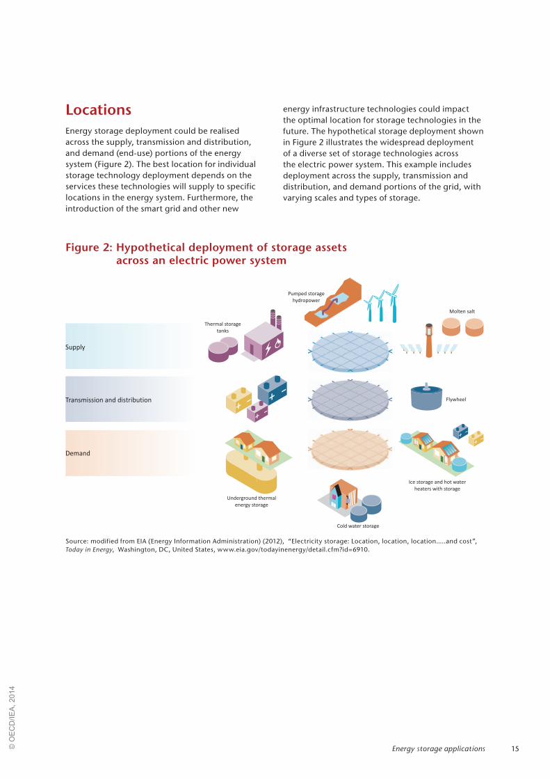
LocationsEnergy storage deployment could be realised across the supply, transmission and distribution, and demand (end-use) portions of the energy system (Figure 2). The best location for individual storage technology deployment depends on the services these technologies will supply to specific locations in the energy system. Furthermore, the introduction of the smart grid and other new
energy infrastructure technologies could impact the optimal location for storage technologies in the future. The hypothetical storage deployment shown in Figure 2 illustrates the widespread deployment of a diverse set of storage technologies across the electric power system. This example includes deployment across the supply, transmission and distribution, and demand portions of the grid, with varying scales and types of storage.
Figure 2: Hypothetical deployment of storage assets across an electric power system
Source: modified from EIA (Energy Information Administration) (2012), “Electricity storage: Location, location, location…..and cost”, Today in Energy, Washington, DC, United States, www.eia.gov/todayinenergy/detail.cfm?id=6910.
Pumped storage
hydropower
Thermal storage
tanks
Underground thermal
energy storage
Cold water storage
Molten salt
Flywheel
Storage_2014_RM_Fig_02
Demand
Transmission and distribution
Supply
Ice storage and hot water
heaters with storage
Energy storage applications© O
EC
D/IE
A, 2
014

16 Technology Roadmap Energy storage
Figure 3: Maturity of energy storage technologies
Source: Decourt, B. and R. Debarre (2013), “Electricity storage”, Factbook, Schlumberger Business Consulting Energy Institute, Paris, France and Paksoy, H. (2013), “Thermal Energy Storage Today” presented at the IEA Energy Storage Technology Roadmap Stakeholder Engagement Workshop, Paris, France, 14 February.
Flywheel (high speed)Lithium-based batteries
Ice storage
Current maturity level
Thermal storageElectricity storage
Research and development Demonstration and deployment Commercialisation
Thermochemical
Residential hot waterheaters with storage
Molten salt
Pit storage
Underground thermalenergy storage (UTES)
Cold water storage
Ca
pit
al
req
uir
em
en
tx
tech
no
log
yri
sk
Pumped Storage Hydropower (PSH)
Compressed air energy storage (CAES)
Synthetic natural gas
HydrogenAdiabatic CAES
Superconducting magneticenergy storage (SMES)
Supercapacitor
Flow batteries
Flywheel (low speed)
Sodium-sulphur (NaS) batteries
This roadmap defines energy storage technologies in terms of output – electricity versus thermal (heat or cold).9 Today, electricity and thermal storage technologies exist at many levels of development, from the early stages of R&D to mature, deployed technologies.10 The IEA Technology Roadmap: Energy Storage Technology Annex includes in-depth descriptions and project examples for many
9. Hydrogen storage is the subject of the forthcoming IEA technology roadmap on hydrogen storage and so will not be covered in detail here.
10. This development spectrum is roughly equivalent to the This development spectrum is roughly equivalent to the concepts of “Technology Readiness Levels” (TRLs) and Manufacturing Readiness Levels (MRLs).
energy storage technologies. In Figure 3, some key technologies are displayed with respect to their associated initial capital investment requirements and technology risk versus their current phase of development (i.e. R&D, demonstration and deployment, or commercialisation phases).11
11. For the sake of concision, only a limited number of energy storage technologies are included in Figure 3. This list is not meant to be comprehensive, but to highlight some of the promising and successfully deployed technologies in the energy system.
Status of energy storage technologies today
Current installed capacityWhile some datasets exist that quantify the storage capabilities found in today's energy systems, attempts to comprehensively summarise the current global installed capacity for energy storage struggle from a lack of widespread and accessible data as well as conflicting definitions regarding what should be included in the baseline.
Today, it is somewhat easier to establish a baseline for some countries, including the United States and Japan as well as some regions in Europe, for
a specific subset of energy storage technologies. In these cases, data can be found for large-scale, grid-connected electricity storage systems. These data reveal that at least 140 gigawatts (GW) of large-scale energy storage is currently installed in electricity grids worldwide. The vast majority (99%) of this capacity is comprised of PSH technologies (Figure 4). The other 1% includes a mix of battery, CAES, flywheels, and hydrogen storage (Ying, 2011; US DOE, 2013).
© O
EC
D/IE
A, 2
014

17Status of energy storage technologies today
Remaining data gaps challenge attempts to establish a reliable baseline for current installed capacity and work in analysing future potential for both connected and off-grid systems. The potential of distributed energy storage in existing
infrastructure has not yet been evaluated; however, the ECES IA recently started a new activity on this topic (Annex 28, “Integration of Renewable Energy by Distributed Energy Storage”).
Figure 4: Current global installed grid-connected electricity storage capacity (MW)
Source: IEA analysis and EPRI (Electric Power Research Institute) (2010), “Electrical Energy Storage Technology Options”, Report, EPRI, Palo Alto, California.
PSH 140 000
CAES 440
Sodium-sulphur
304
Lithium-ion 100
Lead-acid 70
Nickel-cadmium 27
Flywheel 25
Redox-flow 10Other 976
For thermal energy storage, one of the most common technologies installed today is domestic hot water tanks. Other technologies, such as ice and chilled water storage, play an important role in in several countries, including Australia, the United States, China and Japan, as utilities seek to
reduce peak loads and consumers seek to lower their electricity bills. Underground thermal energy storage (UTES) systems are frequently found in Canada, Germany, and many other European countries (IEA, 2011).
Table 5: Estimated thermal energy storage capacity in the United States in 2011
Technology type (application) Units (MW) in 2011
Ice storage (commercial buildings and district cooling) 1 000
Cold-water storage (district cooling) 355
Electric thermal storage (heating) 1 000
Source: O’Donnell, A. and K-A. Adamson (2012), “Thermal Storage for HVAC in Commercial buildings, District Cooling and Heating, Utility and Grid Support Applications, and High-Temperature Storage at CSP Facilities”, Pike Research, New York.
© O
EC
D/IE
A, 2
014

18 Technology Roadmap Energy storage
Brief technology descriptions and examples of existing projects for both thermal and electricity storage technologies can be found in the IEA Energy Storage Technology Annex. Table 6 depicts a range
of energy storage technologies in terms of several technology characteristics. As these technologies cannot store and discharge energy without losses efficiency values are included in this table.
Table 6: Energy storage technologies: current status and typical locations in today’s energy system*
Technology Location* Output Efficiency (%)
Initial investment cost
(USD/kW)
Primary application Example projects
PSH Supply Electricity 50 - 85 500 - 4 600 Long-term storage
Goldisthal Project (Germany), Okinawa Yanbaru Seawater PSH Facility (Japan), Pedreira PSH Station (Brazil)
UTES Supply Thermal 50 - 90 3 400 - 4 500 Long-term storage
Drake Landing Solar Community (Canada), Akershus University Hospital and Nydalen Industrial Park (Norway)
CAES Supply Electricity 27 - 70 500 - 1 500 Long-term storage, arbitrage
McIntosh (Alabama, United States), Huntorf (Germany)
Pit storage Supply Thermal 50 - 90 100 - 300 Medium temperature applications
Marstal district heating system (Denmark)
Molten salts Supply Thermal 40 - 93 400 - 700 High-temperature applications
Gemasolar CSP Plant (Spain)
Batteries Supply, demand
Electricity 75 - 95 300 - 3 500 Distributed/ off-grid storage,
short-term storage
NaS batteries (Presidio, Texas, United States and Rokkasho Futamata Project, Japan), Vanadium redox flow (Sumimtomo’s Densetsu Office, Japan), Lead-acid (Notrees Wind Storage Demonstration Project, United States), Li-ion (AES Laurel Mountain, United States), Lithium Polymer (Autolib, France)
© O
EC
D/IE
A, 2
014

19
Technology Location* Output Efficiency (%)
Initial investment cost
(USD/kW)
Primary application Example projects
Thermochemical Supply, demand
Thermal 80 - 99 1 000 - 3 000 Low, medium, and high-
temperature applications
TCS for Concentrated Solar Power Plants (R&D)
Chemical- hydrogen storage
Supply, demand
Electrical 22 - 50 500 - 750 Long-term storage
Utsira Hydrogen Project (Norway), Energy Complementary Systems H2Herten (Germany)
Flywheels T&D Electricity 90 - 95 130 - 500 Short-term storage
PJM Project (United States)
Supercapacitors T&D Electricity 90 - 95 130 - 515 Short-term storage
Hybrid electric vehicles (R&D phase)
Superconducting magnetic energy storage (SMES)
T&D Electricity 90 - 95 130 - 515 Short-term storage
D-SMES (United States)
Solid media storage
Demand Thermal 50 - 90 500 - 3 000 Medium temperature applications
Residential electric thermal storage (USA)
Ice storage Demand Thermal 75 - 90 6 000 - 15 000 Low-temperature applications
Denki University (Tokyo, Japan) , China Pavilion project (China)
Hot water storage (residential)
Demand Thermal 50 - 90 ** Medium temperature applications
Peak demand reduction (France), TCES (United States)
Cold-water storage
Demand Thermal 50 - 90 300 - 600 Low-temperature applications
Shanghai Pudong International Airport (China)
Note: see IEA Energy Storage Technology Annex for more information. www.iea.org/publications/freepublications/publication/name,36573,en.html.
* Typical locations in today’s energy system. These locations may change as the energy system evolves.
** Energy storage capabilities present in hot water storage tanks can be utilised for negligible additional cost.
Sources: IEA (2014a), Energy Technology Perspectives, forthcoming, OECD/IEA, Paris, France. IEA (2011), Technology Roadmap: Energy Efficient Buildings: Heating and Cooling Equipment, OECD/IEA, Paris, France. Black & Veatch (2012), “Cost and performance data for power generation technologies”, Cost Report, Black & Veatch, February. EPRI (Electric Power Research Institute) (2010), “Electrical Energy Storage Technology Options”, Report, EPRI, Palo Alto, California. Eyer, J. and G. Corey, (2010), ”Energy Storage for the Electricity Grid: Benefits and Market Potential Assessment Guide”, Sandia National Laboratory, Albuquerque, NM, United States. IEA-ETSAP and IRENA (2013), “Thermal Energy Storage” Technology Brief E17, Bonn, Germnay. IEA-ETSAP (Energy Technology Systems Analysis Programme) and IRENA (International Renewable Energy Agency) (2012), “Electricity Storage”,Technology Policy Brief E18, Bonn, Germany. “Power Tower Technology Roadmap and Cost Reduction Plan”, Sandia National Laboratories (2011), Albuquerque, NM and Livermore, CA, United States.
Table 6: Energy storage technologies: Current status and typical locations in today’s energy system* (continued)
Status of energy storage technologies today© O
EC
D/IE
A, 2
014
20 Technology Roadmap Energy storage
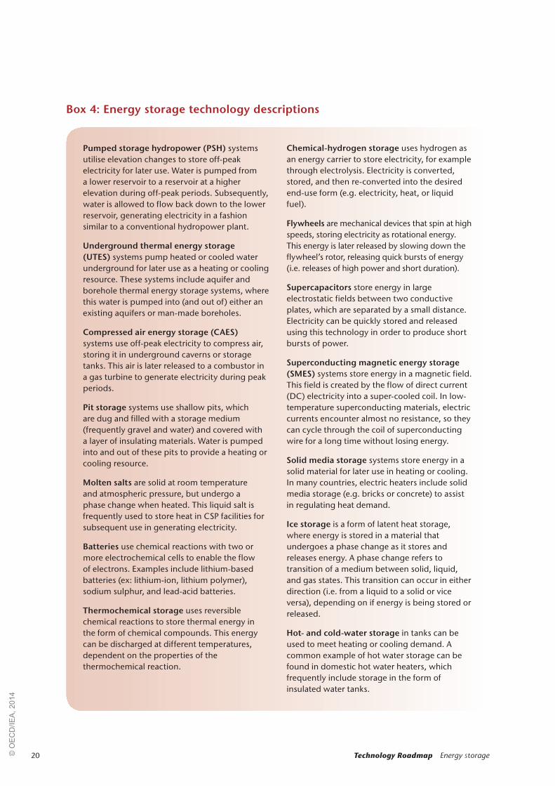
Pumped storage hydropower (PSH) systems utilise elevation changes to store off-peak electricity for later use. Water is pumped from a lower reservoir to a reservoir at a higher elevation during off-peak periods. Subsequently, water is allowed to flow back down to the lower reservoir, generating electricity in a fashion similar to a conventional hydropower plant.
Underground thermal energy storage (UTES) systems pump heated or cooled water underground for later use as a heating or cooling resource. These systems include aquifer and borehole thermal energy storage systems, where this water is pumped into (and out of) either an existing aquifers or man-made boreholes.
Compressed air energy storage (CAES) systems use off-peak electricity to compress air, storing it in underground caverns or storage tanks. This air is later released to a combustor in a gas turbine to generate electricity during peak periods.
Pit storage systems use shallow pits, which are dug and filled with a storage medium (frequently gravel and water) and covered with a layer of insulating materials. Water is pumped into and out of these pits to provide a heating or cooling resource.
Molten salts are solid at room temperature and atmospheric pressure, but undergo a phase change when heated. This liquid salt is frequently used to store heat in CSP facilities for subsequent use in generating electricity.
Batteries use chemical reactions with two or more electrochemical cells to enable the flow of electrons. Examples include lithium-based batteries (ex: lithium-ion, lithium polymer), sodium sulphur, and lead-acid batteries.
Thermochemical storage uses reversible chemical reactions to store thermal energy in the form of chemical compounds. This energy can be discharged at different temperatures, dependent on the properties of the thermochemical reaction.
Chemical-hydrogen storage uses hydrogen as an energy carrier to store electricity, for example through electrolysis. Electricity is converted, stored, and then re-converted into the desired end-use form (e.g. electricity, heat, or liquid fuel).
Flywheels are mechanical devices that spin at high speeds, storing electricity as rotational energy. This energy is later released by slowing down the flywheel’s rotor, releasing quick bursts of energy (i.e. releases of high power and short duration).
Supercapacitors store energy in large electrostatic fields between two conductive plates, which are separated by a small distance. Electricity can be quickly stored and released using this technology in order to produce short bursts of power.
Superconducting magnetic energy storage (SMES) systems store energy in a magnetic field. This field is created by the flow of direct current (DC) electricity into a super-cooled coil. In low-temperature superconducting materials, electric currents encounter almost no resistance, so they can cycle through the coil of superconducting wire for a long time without losing energy.
Solid media storage systems store energy in a solid material for later use in heating or cooling. In many countries, electric heaters include solid media storage (e.g. bricks or concrete) to assist in regulating heat demand.
Ice storage is a form of latent heat storage, where energy is stored in a material that undergoes a phase change as it stores and releases energy. A phase change refers to transition of a medium between solid, liquid, and gas states. This transition can occur in either direction (i.e. from a liquid to a solid or vice versa), depending on if energy is being stored or released.
Hot- and cold-water storage in tanks can be used to meet heating or cooling demand. A common example of hot water storage can be found in domestic hot water heaters, which frequently include storage in the form of insulated water tanks.
Box 4: Energy storage technology descriptions
© O
EC
D/IE
A, 2
014

21
Electricity storage Electricity storage technologies can be grouped into three main time categories (short-term, long-term and distributed battery storage) based on the types of services that they provide. Systems include a number of technologies in various stages of development. Broadly speaking, PSH, CAES, and some battery technologies are the most mature, while flow batteries, SMES, supercapacitors and other advanced battery technologies are currently at much earlier stages of development.
Major R&D efforts exist for many electricity storage technologies. In particular, battery and hydrogen technologies have received significant funding in support of research, development, and demonstration projects in regions including the United States, Japan, and Germany. The primary technology characteristics used in assessing a technology’s potential for use in specific applications include storage and operation properties (including energy and power capacity, density, efficiency, scale, discharge capacity, response time, and lifetime or cycling performance), and cost (Inage 2009).
Short-term (seconds-minutes) storage applications
Supercapacitors and SMES technologies use static electric or magnetic fields to directly store electricity. Flywheels store and then release electricity from the grid by spinning and then applying torque to its rotor to slow rotation. These technologies generally have high cycle lives and power densities, but much lower energy densities. This makes them best suited for supplying short bursts of electricity into the energy system. Modern technologies struggle in today’s energy markets due to high costs relative to their market value.
Distributed battery storage
Batteries use chemical reactions with two or more electrochemical cells to enable the flow of electrons (e.g. lithium-based12, NaS, and lead-acid batteries). The battery is charged when excess power is available and later discharged as needed. This storage technology can be used for both short- and long-term applications (i.e. both power and energy services) and benefits from being highly scalable and efficient (Rastler, 2011). Furthermore,
12. Examples of lithium-based batteries include lithium-ion, Examples of lithium-based batteries include lithium-ion, lithium-polymer, lithium-air, and lithium -ceramic.
it can be installed throughout the energy system and has already achieved limited deployment in both distributed and centralised systems for mobile and stationary applications at varying scales. Widespread deployment, however, is hampered by challenges in energy density, power performance, lifetime, charging capabilities, and costs.
Long-term (hours-seasons) storage applications
PSH are currently the most mature and widespread method for long-term electricity storage (IEA, 2012). In addition, two CAES facilities have been successfully used by utilities in the United States and Germany for several decades (Konidena, 2012). These technologies face high upfront investment costs due to typically large project sizes and low projected efficiencies for non-adiabatic CAES design proposals. In the case of pumped hydro and CAES, geographic requirements can lead to higher capital costs.
Today, there are two CAES systems in commercial operation, both of which use natural gas as their primary onsite fuel and are equipped with underground storage caverns. The larger of these two facilities is a 321 MW system in Huntorf, Germany. Commissioned in 1978, this system uses two caverns (300 000 m3) to provide up to 425 kilograms per second (kg/s) of compressed air (pressure up to 70 bars) produce efficiencies up to 55%. The other system, in McIntosh, Alabama, uses flue gas from its natural gas power plant for preheating to increase overall power plant efficiency (US DOE, 2013).
Hydrogen storage
Hydrogen storage can be used for long-term energy applications. Electricity is converted into hydrogen, stored, and then re-converted into the desired end-use form (e.g. electricity, heat, synthetic natural gas, pure hydrogen or liquid fuel). These storage technologies have significant potential due to their high energy density, quick response times, and potential for use in large-scale energy storage applications. However, these technologies struggle with high upfront costs, low overall efficiencies and safety concerns, as well as a lack of existing infrastructure for large-scale applications (e.g. hydrogen storage for fuel-cell vehicles). This type of electricity storage will be discussed in-depth in the forthcoming IEA Hydrogen Technology Roadmap.
Status of energy storage technologies today© O
EC
D/IE
A, 2
014

22 Technology Roadmap Energy storage
The city of Presidio, Texas, is located in the deserts of West Texas on the banks of the Rio Grande River. Prior to 2010, the city suffered from a large number of power outages because the only transmission line bringing power from neighbouring Marfa, Texas to Presidio was a 60 mile, 69 kilovolt (kV) line constructed in 1948. This aging transmission line crosses harsh terrain and its deteriorating condition and frequent lighting strikes have resulted in unreliable power for the residents of Presidio.
Electric Transmission Texas proposed the construction of a NaS battery system, a second 138/69kV autotransformer at Marfa’s Alamito Creek Substation, and a new 69kV transmission line connecting the Alamito Creek Substation to Presidio. Both the Public Utility Commission of Texas (PUCT) and the Electric Reliability Council of Texas (ERCOT) approved the proposal. The battery was energised in late March 2010 and dedicated on 8 April 2010 (ETT, 2013).
The energy storage system is a 4MW, 32MWh NaS battery consisting of 80 modules, each weighing 3 600 kg. The total cost of the battery system was USD 25 million and included USD 10 million for construction of the building to house the batteries (built by Burns & McDonnell) and the new substation at Alamito Creek. The proposed additional transmission line had an approximate cost of USD 45 million, yielding a total project cost of USD 70 million (Reske, 2010). The battery system is controlled by an energy management system with a controller and power converter that facilitates the battery charging and discharging process in response to real-time conditions of the grid (S&C Electric, 2013).
The Presidio battery system and additional transmission line were financed through ERCOT as a “necessary transmission upgrade” for the residents of Presidio, even though the cost to supply the city with reliable power was high compared to the number of people served and the total amount of power sent to residents. As such, the cost was shared among all transmission and distribution providers and passed on to all rate-paying customers through a common ERCOT-wide “postage-stamp transmission rate” fee. It has been and continues to be ERCOT’s policy to use this approach to pay for all transmission upgrades necessary to ensure reliable service to all customers.
The primary purpose of the Presidio NaS battery is to provide backup power for an aging transmission line and to reduce voltage fluctuations and momentary outages for the city and residents of Presidio. The battery system can respond quickly to rapid disturbances as well as supply uninterrupted power for up to eight hours in the case of an extended transmission outage. Between 2001 and 2006 there were 247 power outages, including nine long-term outages with an average duration of 6.8 hours. Additionally, between 8 July and 8 September 2007 there were 81 poor voltage quality events (ERCOT, 2008). The NaS battery was designed to minimise these power disturbances and fluctuations starting from its inception in 2010 until the new 69kV line could be completed in 2012. After completion of the new transmission line, the battery system remains a source of both voltage support and backup power in case fierce storms (that are common in the West Texas region) disrupt Presidio’s main electricity supply line.
Box 5: Sodium-sulphur battery for transmission infrastructure deferral and voltage regulation in the United States
Thermal storageThermal energy storage (TES) technologies operate with a goal of storing energy for later use as heating or cooling capacity. Individual TES technologies operate in the generation and end-use steps of the energy system and can be grouped by
storage temperature: low, medium, high. Thermal storage technologies are well suited for an array of applications including seasonal storage on the supply-side and demand management services on the demand-side portion of the energy system (IEA-ETSAP, 2013). As heating and cooling requirements
© O
EC
D/IE
A, 2
014

23
represent 45% of the total energy use in buildings, these demand-side services can represent significant value to the energy system (IEA, 2011).
Some thermal energy storage technologies have already realised significant levels of deployment in electricity and heat networks, including UTES systems and ice storage systems for residential cooling. Further, some end-use technologies that have already been deployed to meet other societal requirements include TES capabilities, though this potential is not currently being fully realised (e.g. residential hot water heaters). Today’s R&D in thermal energy storage is primarily focused on reducing the costs of high-density storage, including thermochemical process and phase-change material (PCM) development (European Association for Storage of Energy [EASE]/EERA, 2013).
Thermal energy storage for low-temperature (<10°C) applications
Cold-water storage tanks in commercial and industrial facilities are already installed around the world to supply cooling capacity. Larger UTES systems, including aquifer thermal energy storage (ATES) and borehole thermal energy storage (BTES), have been successfully commercialised in order to provide both heating and cooling capacity in countries such as the Netherlands, Sweden, Germany, and Canada.
Due to the higher energy storage densities seen with PCMs compared to sensible heat storage, the United States and Japan have already installed significant amounts of thermal storage that uses ice for cooling applications. In the United States, an estimated 1 GW of ice storage has been deployed to reduce peak energy consumption in areas with high numbers of cooling-degree days (O’Donnell and Adamson, 2012).
Beyond water, significant R&D activities have been dedicated to developing other PCMs for the transportation of temperature sensitive products. Thermochemical storage – where reversible chemical reactions are used to store cooling capacity in the form of chemical compounds – is currently a focus in thermal storage R&D projects due to its ability to achieve energy storage densities of five to 20 times greater than sensible storage.
Thermal energy storage for medium temperature (10°C-250°C) applications
Distributed thermal energy storage has been around for decades in countries such as New Zealand, Australia and France that use storage capabilities in electric hot water storage heaters. By allowing the heater system to be controlled by the local utility (or distribution company in cases with market liberalisation), the demand from these systems is used to manage local congestion and
Waste heat represents a significant opportunity for improving the efficiency of global energy systems. The potential magnitude of its contribution is difficult to quantify, however, as this value is a function of not only the amount of heat available but also the quality (including temperature and pressure) of this heat. Furthermore, potential uses for waste heat resources are dependent on demand in nearby areas and on the availability of thermal energy networks. These difficulties have prompted new regulatory measures including the recent European Union Energy Efficiency Directive (EU, 2012) that calls for member countries
to complete comprehensive assessments of national heating and cooling potentials from resources including waste heat.
R&D efforts focused on improving system maintenance and control systems could provide a key to unlocking these waste heat resources. In addition, thermal energy storage could be used to match heat supply with demand where temporal or geographic gaps exist, in the presence or absence of district heating and cooling infrastructure.
Box 6: Increasing system efficiency via waste heat utilisation
Status of energy storage technologies today© O
EC
D/IE
A, 2
014
24 Technology Roadmap Energy storage
has reduced residential peak demand. In France, for example, thermal storage capabilities in electric water heaters are used to achieve a 5% annual peak reduction (Box 7).
Borehole and aquifer UTES systems have been successfully deployed on a commercial scale to provide heating capacity in the Netherlands, Norway and Canada. These systems utilise holes drilled deep into the ground to store and release energy for heating. Pit storage – where hot water is stored in a covered pit – is used throughout Denmark’s district heating networks.
Thermochemical storage systems can be designed to discharge thermal energy at different temperatures, making them an appealing option for medium temperature thermal energy storage applications. As with low-temperature applications, this storage mechanism’s relatively high energy density potential has prompted significant R&D efforts.
Thermal energy storage for high-temperature (>250°C) applications
Perhaps the most well-known form of thermal energy storage for high-temperature applications is currently found in molten salts. This material is used to increase the dispatchability of power from CSP facilities by storing several hours of thermal energy for use in electricity generation (IEA, 2010). Heat storage with PCMs, thermochemical energy storage, and waste heat utilisation methods offer many potential opportunities. However, these technologies will need to overcome containment vessel design and material stability challenges at very high temperatures before they can achieve widespread deployment.
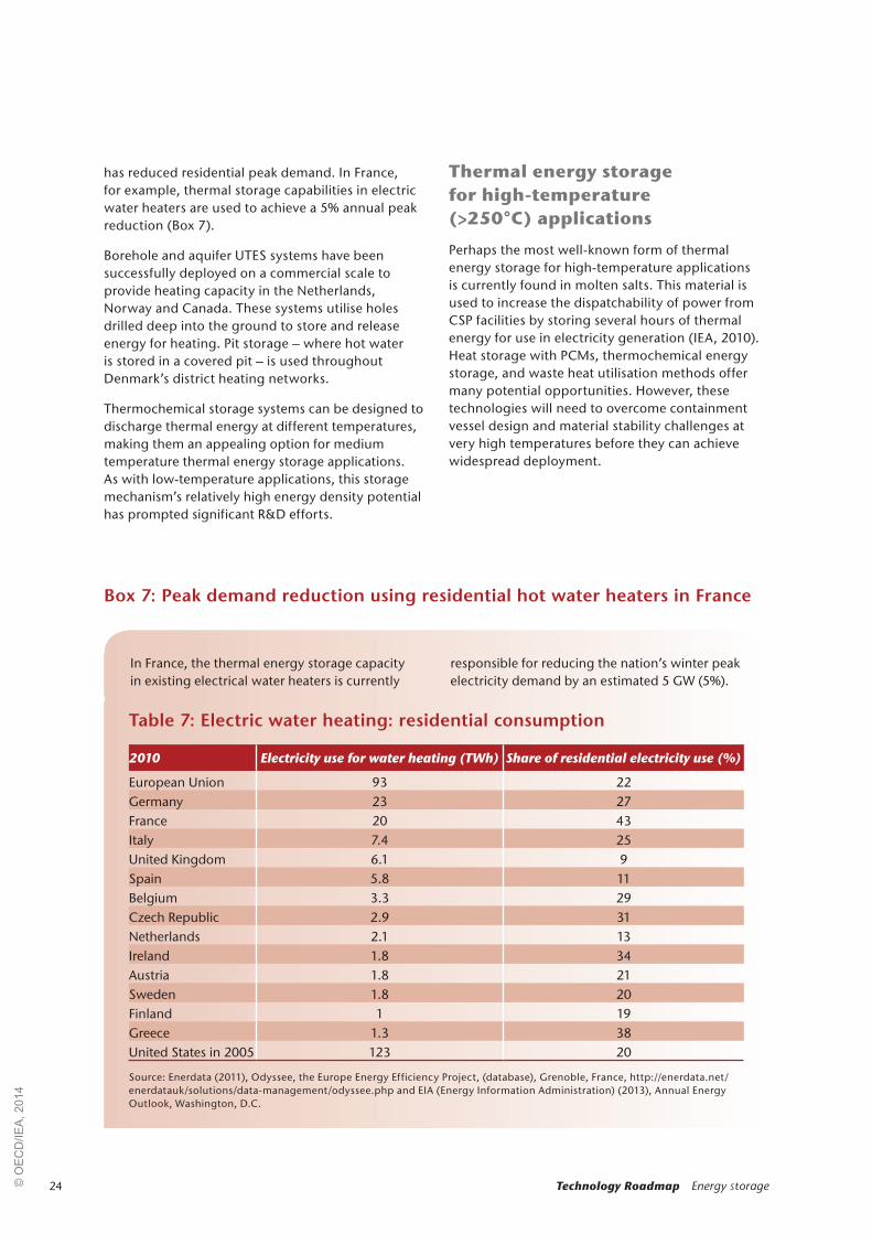
In France, the thermal energy storage capacity in existing electrical water heaters is currently
responsible for reducing the nation’s winter peak electricity demand by an estimated 5 GW (5%).
Box 7: Peak demand reduction using residential hot water heaters in France
Table 7: Electric water heating: residential consumption
2010 Electricity use for water heating (TWh) Share of residential electricity use (%)
European Union 93 22Germany 23 27France 20 43Italy 7.4 25United Kingdom 6.1 9Spain 5.8 11Belgium 3.3 29Czech Republic 2.9 31Netherlands 2.1 13Ireland 1.8 34Austria 1.8 21Sweden 1.8 20Finland 1 19Greece 1.3 38United States in 2005 123 20
Source: Enerdata (2011), Odyssee, the Europe Energy Efficiency Project, (database), Grenoble, France, http://enerdata.net/enerdatauk/solutions/data-management/odyssee.php and EIA (Energy Information Administration) (2013), Annual Energy Outlook, Washington, D.C.
© O
EC
D/IE
A, 2
014
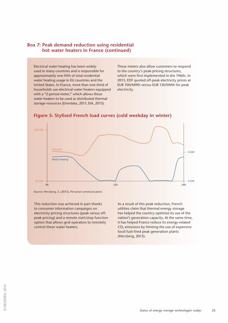
25
This reduction was achieved in part thanks to consumer information campaigns on electricity pricing structures (peak versus off-peak pricing) and a remote start/stop function option that allows grid operators to remotely control these water heaters.
As a result of this peak reduction, French utilities claim that thermal energy storage has helped the country optimise its use of the nation’s generation capacity. At the same time, it has helped France reduce its energy-related CO2 emissions by limiting the use of expensive fossil fuel-fired peak generation plants (Hercberg, 2013).
Electrical water heating has been widely used in many countries and is responsible for approximately one-fifth of total residential water heating usage in EU countries and the United States. In France, more than one-third of households use electrical water heaters equipped with a “2-period meter,” which allows these water heaters to be used as distributed thermal storage resources (Enerdata, 2011; EIA, 2013).
These meters also allow customers to respond to the country’s peak-pricing structures, which were first implemented in the 1960s. In 2013, EDF quoted off-peak electricity prices at EUR 100/MWh versus EUR 130/MWh for peak electricity.
Figure 5: Stylised French load curves (cold weekday in winter)
Source: Hercberg, S. (2013), Personal communication.
100 GW
60 GW 0 GW
6 GW
0h 12h 24h
Water heating
National
Box 7: Peak demand reduction using residential hot water heaters in France (continued)
Status of energy storage technologies today© O
EC
D/IE
A, 2
014

26 Technology Roadmap Energy storage
The vision presented in this roadmap is that of electricity storage in the 2DS of Energy Technology Perspectives 2014. Due to data and modelling capability constraints, this vision is limited to the use of four categories of grid-connected electricity storage technologies13 for supplying daily energy storage needs in China, India, the European Union and the United States, where load-levelling applications help optimise the high penetration of variable renewable generation. Within these constraints, under a scenario where variable renewable electricity reaches between 27% and 44% of electricity production in 2050, an estimated 310 GW of additional storage would be needed in these four major regions, which make up 85% of electricity demand in 2050.
To complement this four-region 2DS vision for energy storage deployment to 2050, three country-specific visions are also included.14 Researchers in these countries, using scenarios developed to achieve power sector decarbonisation objectives in 2050, supported the development of these cases.
This limited 2DS vision does not imply a lack of large-scale potential for thermal energy storage technologies nor for other electricity storage systems, including those for application in remote communities and off-grid. Rather, it illustrates the need to establish international and national data co-operation to support more comprehensive global energy storage potential assessments, foster energy storage research, monitor progress, and assess R&D bottlenecks. Furthermore, the significant heating and cooling demand in buildings and heating demand in industry in the 2DS illustrate some of the potential applications for thermal energy storage technologies. These demands are shown in the energy storage roadmap insights.
Electricity storage technologies could provide services in a variety of applications across the energy system, from addressing power quality to providing energy arbitrage or seasonal storage. However, assessing the size of the future markets for each application, and the penetration that storage technologies could reach in each, depends fully on the characteristics of specific electricity systems:
13. Pumped-storage hydropower (PSH), compressed air energy storage (CAES), flow batteries, and a generalised “other” battery technology.
14. For the United States, Germany and China.
the competing options available, the penetration and location of variable renewables, and the level of development of electricity grids (IEA, 2014b).
Three variants of the 2DS are developed – the 2DS; a “breakthrough” scenario with aggressive cost reductions for storage technologies; and an “electric vehicle” (EV) scenario with demand response from charging the EV fleet, adding flexibility to the system – where storage technologies compete for these services with future sources of thermal electricity generation and demand response under a variety of assumptions. In the 2DS, daily electricity storage costs are assumed to reach the current cost of pumped hydro storage technologies, while in the breakthrough scenario aggressive cost reductions facilitate increased deployment of storage.
In the section following this constrained vision for daily electricity storage, actions are recommended take a more holistic approach. Specifically, they revert to the broader perspective of both electricity and thermal energy storage technologies across the whole energy system.
The ETP 2014 scenarios for a clean energy transitionThe ETP 2014 2DS is taken as the reference scenario in this roadmap. The foremost feature of the 2DS is a core of clean electricity, with renewable energy technologies increasing their share of worldwide electricity generation from about 20% to 65% by 2050, with variable renewables supplying 29% of total electricity production globally.
Vision for deployment to 2050
© O
EC
D/IE
A, 2
014

27Vision for deployment to 2050
The ETP 2014 publication explores the future role of daily electricity storage technologies under a range of sensitivities regarding future costs and performance of storage and competing technologies, including flexible thermal power generation and to some extent, demand response (IEA, 2014b). Three of these variants are reproduced
in this roadmap:
z the 2°C Scenario (2DS)
z a "breakthrough" scenario, with aggressive cost reductions in storage technologies
z an "EV" scenario, where demand response from "smart" charging of the electric vehicle fleet in the 2DS provides additional flexibility to the system.
The IEA ETP 2DS describes how technologies across all energy sectors may be transformed by 2050 to give an 80% chance of limiting average global temperature increase to 2°C. It sets the target of cutting energy-related CO2 emissions by more than half by 2050 (compared with 2009) and ensuring that they continue to fall thereafter. The 2DS acknowledges that transforming the energy sector is vital but not the sole solution: the goal can only be achieved if CO2 and GHG emissions in non-energy sectors are also reduced. The 2DS is broadly consistent with the World Energy Outlook 450 Scenario through to 2035.
The model used for this analysis is a bottom-up TIMES (The Integrated MARKAL-EFOM System) model that uses cost optimisation to identify least-cost mixes of technologies and fuels to meet energy demand, given constraints such
as the availability of natural resources. The ETP global 28-region model permits the analysis of fuel and technology choices throughout the energy system, including about 500 individual technologies. The model, which has been used in many analyses of the global energy sector, is supplemented by detailed demand-side models for all major end uses in the industry, buildings and transport sectors.
Large regional variations exist – reflecting differences in renewable resource availability and alternatives for decarbonisation elsewhere in the energy system – with respect to the level of variable renewable electricity generation, which ranges from 20% to 55% worldwide. Storage will compete with other options to provide the flexibility needed to accommodate these resources, which sets the context for the vision for storage technologies in this roadmap.
Box 8. Energy Technology Perspectives (ETP) 2DS
Figure 6: Share of electricity generated from variable renewables (%) by region in the 2DS
0%
5%
10%
15%
20%
25%
30%
35%
40%
45%
50%
2010 2030 2050 2010 2030 2050 2010 2030 2050 2010 2030 2050
China India European Union United States
Shar
e of
var
iabl
e re
new
able
s in
el
ectr
icity
gen
erat
ion
(%)
© O
EC
D/IE
A, 2
014

28 Technology Roadmap Energy storage
Figure 7: Electricity storage capacity for daily electricity storage by region in 2011 and 2050 for ETP 2014 scenarios
0
20
40
60
80
100
120
140
160
180
China India European Union United States
Giga
wat
ts (G
W)
2011
2DS
Breakthrough
EV
Three scenarios for electricity storage deploymentThe ETP 2DS scenario serves as a reference case, determining the capacity expansion of power generation technologies from now to 2050 to meet low-carbon objectives. The flexibility of the resulting system is then explored using a linear dispatch model where the cost of operating the electricity system is minimised by determining the dispatch of generation and storage technologies during every hour in a given year. This approach permits a detailed assessment of the storage needs within the power generation fleet from the 2DS under a range of conditions with other technologies
competing to provide the same services. Full detail on the modelling and scenario assumptions can be found in Annex B.
The 2DS assumes the cost of technologies providing daily storage for arbitrage applications in 2050 will be that of the lowest-cost technology providing this service today: PSH. In the ‘breakthrough’ scenario, aggressive reductions in specific energy (per MWh) and power capacity (per MW) storage costs facilitate an increased deployment of storage. Finally, in the electric vehicle scenario, charging strategies for offsetting peak demand are widely employed and the need for additional large-scale storage in the six- to eight-hour duration range is reduced. The resulting electricity storage capacities in 2050 are summarised in Figure 7.
Cost targets in a "breakthrough" scenario
The "breakthrough" scenario is designed as an estimation of the highest penetration of daily electricity storage in the 2DS scenario. This scenario assumes aggressive cost reductions in electricity storage technologies for arbitrage applications, where these technologies become competitive with the least expensive option currently providing arbitrage services.15 This result translates to a levellised cost of energy (LCOE) for daily bulk storage of approximately USD 90/MWh
15. Currently a combined cycle gas turbine operating at load Currently a combined cycle gas turbine operating at load factors of 30% to 60%.
(Figure 8). The LCOE includes the cost of the initial technology infrastructure investment, operation and maintenance, and electricity used to charge the storage facilities.
At this LCOE, electricity storage technologies provide all the flexibility requirements in all regions in the 2DS. These cost reductions, however, are highly ambitious – for PSH and CAES, significant reductions in civil engineering costs have already reduced the overall cost of PSH. As these costs account for nearly half of the initial capital investment, improvements in the turbine technology itself would have a relatively low overall impact. However, because of the high initial capital investments required for these facilities, potential
© O
EC
D/IE
A, 2
014
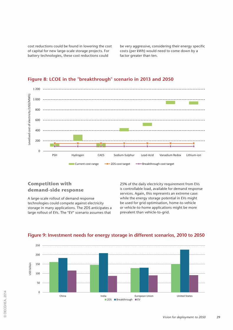
29
cost reductions could be found in lowering the cost of capital for new large-scale storage projects. For battery technologies, these cost reductions could
be very aggressive, considering their energy specific costs (per kWh) would need to come down by a factor greater than ten.
Figure 8: LCOE in the "breakthrough" scenario in 2013 and 2050
Figure 9: Investment needs for energy storage in different scenarios, 2010 to 2050
0
200
400
600
800
1 000
1 200
PSH Hydrogen CAES Sodium-Sulphur Lead-Acid Vanadium Redox Lithium-ion
Leve
lise
dco
sto
fe
lect
rici
ty(U
SD
/MW
h)
Current cost range 2DS cost target Breakthrough cost target
0
50
100
150
200
250
China India European Union United States
USD
bill
ion
2DS Breakthrough EV
Competition with demand-side response
A large-scale rollout of demand response technologies could compete against electricity storage in many applications. The 2DS anticipates a large rollout of EVs. The "EV" scenario assumes that
25% of the daily electricity requirement from EVs is controllable load, available for demand response services. Again, this represents an extreme case: while the energy storage potential in EVs might be used for grid optimisation, home-to-vehicle or vehicle-to-home applications might be more prevalent than vehicle-to-grid.
Vision for deployment to 2050© O
EC
D/IE
A, 2
014
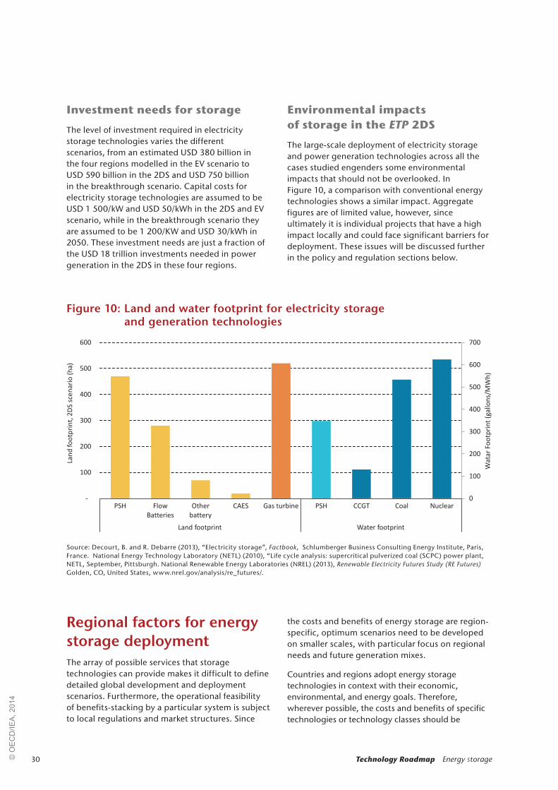
30 Technology Roadmap Energy storage
Investment needs for storage
The level of investment required in electricity storage technologies varies the different scenarios, from an estimated USD 380 billion in the four regions modelled in the EV scenario to USD 590 billion in the 2DS and USD 750 billion in the breakthrough scenario. Capital costs for electricity storage technologies are assumed to be USD 1 500/ kW and USD 50/kWh in the 2DS and EV scenario, while in the breakthrough scenario they are assumed to be 1 200/KW and USD 30/kWh in 2050. These investment needs are just a fraction of the USD 18 trillion investments needed in power generation in the 2DS in these four regions.
Environmental impacts of storage in the ETP 2DS
The large-scale deployment of electricity storage and power generation technologies across all the cases studied engenders some environmental impacts that should not be overlooked. In Figure 10, a comparison with conventional energy technologies shows a similar impact. Aggregate figures are of limited value, however, since ultimately it is individual projects that have a high impact locally and could face significant barriers for deployment. These issues will be discussed further in the policy and regulation sections below.
Figure 10: Land and water footprint for electricity storage and generation technologies
Source: Decourt, B. and R. Debarre (2013), “Electricity storage”, Factbook, Schlumberger Business Consulting Energy Institute, Paris, France. National Energy Technology Laboratory (NETL) (2010), “Life cycle analysis: supercritical pulverized coal (SCPC) power plant, NETL, September, Pittsburgh. National Renewable Energy Laboratories (NREL) (2013), Renewable Electricity Futures Study (RE Futures) Golden, CO, United States, www.nrel.gov/analysis/re_futures/.
0
100
200
300
400
500
600
700
-
100
200
300
400
500
600
PSH Flow
Batteries
Other
battery
CAES Gas turbine PSH CCGT Coal Nuclear
Land footprint Water footprint
Wa
tar
Fo
otp
rin
t(g
allo
ns/
MW
h)
Lan
dfo
otp
rin
t,2
DS
sce
na
rio
(ha
)
Regional factors for energy storage deploymentThe array of possible services that storage technologies can provide makes it difficult to define detailed global development and deployment scenarios. Furthermore, the operational feasibility of benefits-stacking by a particular system is subject to local regulations and market structures. Since
the costs and benefits of energy storage are region-specific, optimum scenarios need to be developed on smaller scales, with particular focus on regional needs and future generation mixes.
Countries and regions adopt energy storage technologies in context with their economic, environmental, and energy goals. Therefore, wherever possible, the costs and benefits of specific technologies or technology classes should be
© O
EC
D/IE
A, 2
014

31
assessed in this context. The following regional characteristics should be taken into account when analysing potential deployment opportunities:
z current and future energy supply mix and demand profiles, including resource availability
z regulatory and market structure, including pricing structure for energy and power services
z status of existing and planned infrastructure investments, including those for transmission and distribution grids
z current level of and future needs for system flexibility
z other competing options for system flexibility.
Box 9: A vision for electricity storage in a high renewable electricity future in the United States
In the United States, significant energy storage potential exists for both electricity and thermal storage technologies. Today, there are over 2GW of installed thermal storage capacity in the country, not including the storage capabilities found in existing infrastructure (e.g. residential hot water heaters and commercial refrigeration systems can provide demand shifting capabilities to the energy system) (Ecofys and Bonneville Power Administration, 2012). There is also an estimated 23 GW of electricity storage capacity connected to the nation’s electricity grid, the vast majority of which is provided by existing pumped hydro systems along with limited amounts of CAES (one system in Alabama), batteries, flywheels, and other storage technologies.
In 2012, the United States Department of Energy published a comprehensive study that evaluated the potential for a national transition to a predominately (up to 80%) renewable electricity supply. The broad goal of this analysis was to determine the maximum proportion of renewable electricity generation that could be incorporated into the Unied States electricity grid using currently available technologies. Explicitly included in the resulting “Renewable Electricity Futures Study” report were three electricity storage technologies – PSH, CAES, and a generalised battery storage system. Furthermore, thermal storage for CSP systems was included to provide system flexibility.*
* In this study, all CSP facilities included six hours of thermal storage.
Figure 11: Generation mix in 2050 in the United States for a range of scenarios (low-demand)
Source: Modified from National Renewable Energy Laboratories (2013), “Renewable Electricity Futures Study” Colorado.
0 10 20 30 40 50 60 70 80 90 100
Baseline
30% RE
40% RE
50% RE
60% RE
70% RE
80% RE
90% RE
Percent renewable electricity
Nuclear
Coal
Natural gas
Biomass
Geothermal
Hydropower
CSP
PV
Wind
(.../...)
Vision for deployment to 2050© O
EC
D/IE
A, 2
014

32 Technology Roadmap Energy storage
Using cost inputs from an independent and external consultancy group, Black and Veatch, this study concluded that currently available renewable electricity technologies could reliably supply 80% of total electricity generation in the United States by 2050, in combination with a more flexible electric system. At this 80% renewables level, almost 50% of total generation in this United States study came from variable renewable resources.
In this future scenario, system flexibility is provided using a portfolio of supply- and demand-side options including flexible generation, grid storage, new transmission lines, a more responsive demand side, and operational changes (e.g. evolved business models and new market rules). Datasets were used with hourly resolution, and resource adequacy had to be met on this basis over a calendar year. Operational considerations below the one-hour timescale were not comprehensively incorporated.
The baseline scenario in the 2012 “Renewable Electricity Futures Study” projects that the nation’s total installed electricity storage capacity would grow to between 103 GW and 152 GW in 2050, exclusive of the thermal
energy storage deployed in conjunction with new CSP facilities. This capacity growth is primarily achieved through the addition of several new CAES facilities. This range is mostly due to assumptions related to transmission grid expansion, where the study observed decreasing total storage capacity with increasing new transmission investments.
It must be noted that this study did not take into account FERC Orders 755 or 784, which were released after the RE Futures analysis was complete and would have likely impacted the cost-benefit analysis for energy storage technologies. Considering the lack of analysis below the one-hour time resolution and the fact that only three large-scale options for energy storage were considered in this study, the total market potential for energy storage in the electricity grid is likely larger than the amount deployed in this analysis. Conversely, new challenges with respect to the technical feasibility of using saline aquifers for new CAES systems have come to light since this study.
Box 9: A vision for electricity storage in a high renewables future in the United States (continued)
Note: this section was prepared with support from the U.S. Department of Energy.
Figure 12: Installed capacity in 2050 as renewable electricity levels increase (low-demand scenario)
Source: National Renewable Energy Laboratories (NREL) (2013), Renewable Electricity Futures Study (RE Futures) Golden, CO, United States, www.nrel.gov/analysis/re_futures/.
0 200 400 600 800 1 000 1 200 1 400 1 600
Baseline
30% RE
40% RE
50% RE
60% RE
70% RE
80% RE
90% RE
Total installed capacity (GW)
Nuclear
Coal
Natural gas
Biomass
Geothermal
Hydropower
CSP
PV
Wind
Storage
© O
EC
D/IE
A, 2
014
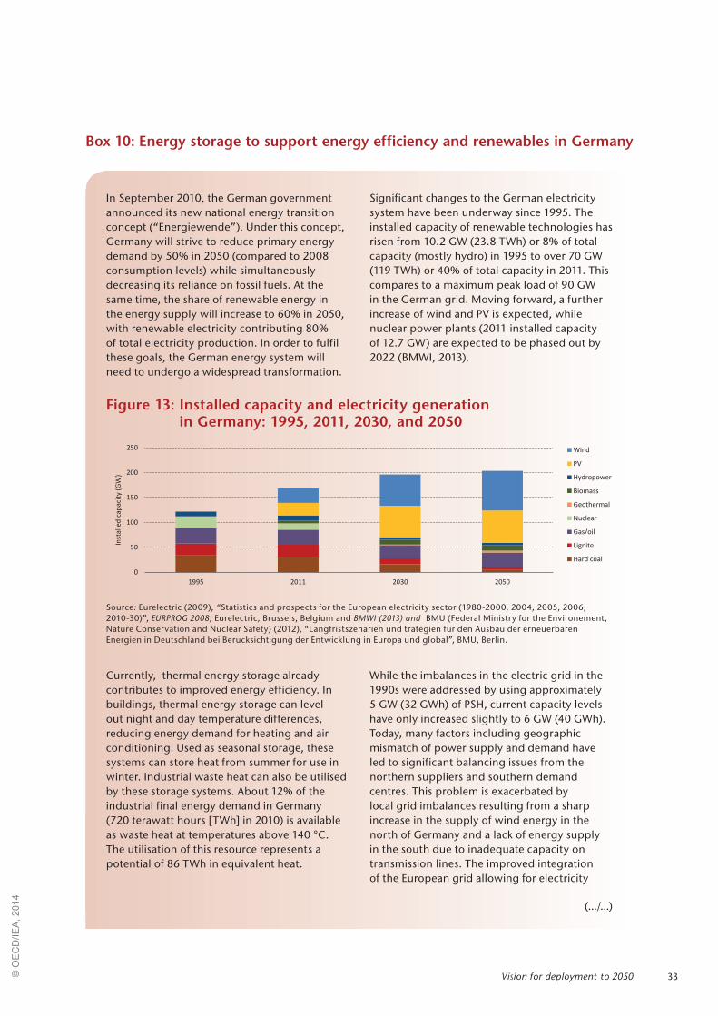
33
In September 2010, the German government announced its new national energy transition concept (“Energiewende”). Under this concept, Germany will strive to reduce primary energy demand by 50% in 2050 (compared to 2008 consumption levels) while simultaneously decreasing its reliance on fossil fuels. At the same time, the share of renewable energy in the energy supply will increase to 60% in 2050, with renewable electricity contributing 80% of total electricity production. In order to fulfil these goals, the German energy system will need to undergo a widespread transformation.
Significant changes to the German electricity system have been underway since 1995. The installed capacity of renewable technologies has risen from 10.2 GW (23.8 TWh) or 8% of total capacity (mostly hydro) in 1995 to over 70 GW (119 TWh) or 40% of total capacity in 2011. This compares to a maximum peak load of 90 GW in the German grid. Moving forward, a further increase of wind and PV is expected, while nuclear power plants (2011 installed capacity of 12.7 GW) are expected to be phased out by 2022 (BMWI, 2013).
Box 10: Energy storage to support energy efficiency and renewables in Germany
Figure 13: Installed capacity and electricity generation in Germany: 1995, 2011, 2030, and 2050
Source: Eurelectric (2009), “Statistics and prospects for the European electricity sector (1980-2000, 2004, 2005, 2006, 2010-30)”, EURPROG 2008, Eurelectric, Brussels, Belgium and BMWI (2013) and BMU (Federal Ministry for the Environement, Nature Conservation and Nuclear Safety) (2012), “Langfristszenarien und trategien fur den Ausbau der erneuerbaren Energien in Deutschland bei Berucksichtigung der Entwicklung in Europa und global”, BMU, Berlin.
Currently, thermal energy storage already contributes to improved energy efficiency. In buildings, thermal energy storage can level out night and day temperature differences, reducing energy demand for heating and air conditioning. Used as seasonal storage, these systems can store heat from summer for use in winter. Industrial waste heat can also be utilised by these storage systems. About 12% of the industrial final energy demand in Germany (720 terawatt hours [TWh] in 2010) is available as waste heat at temperatures above 140 °C. The utilisation of this resource represents a potential of 86 TWh in equivalent heat.
While the imbalances in the electric grid in the 1990s were addressed by using approximately 5 GW (32 GWh) of PSH, current capacity levels have only increased slightly to 6 GW (40 GWh). Today, many factors including geographic mismatch of power supply and demand have led to significant balancing issues from the northern suppliers and southern demand centres. This problem is exacerbated by local grid imbalances resulting from a sharp increase in the supply of wind energy in the north of Germany and a lack of energy supply in the south due to inadequate capacity on transmission lines. The improved integration of the European grid allowing for electricity
(.../...)
Vision for deployment to 2050© O
EC
D/IE
A, 2
014

34 Technology Roadmap Energy storage
imports and exports has enabled Germany to overcome these balancing issues. However, current saturation of interconnectors, combined with Europe’s ambitious plans to increase renewable generation and the potential
decreases in interconnection capacity with neighbouring countries, necessitates a more sustainable solution to maintain balance in both the transmission and distribution portions of the electricity grid (THEMA, 2013).
Box 10: Energy storage to support energy efficiency and renewables in Germany (continued)
Figure 14: Challenges faced by the electricity sector in Germany
Note: figure based on results of research project ‚Bedarfsanalyse Energiespeicher‘ realized by Fraunhofer UMSICHT, supported by the German Federal Ministry of Economics and Technology.
Source: Beier, P. and P. Bretschneider (2013), "Modellbasierte, regional aufgelöste Analyse des Bedarfs an netzgekoppelten elektrischen Energiespeichern zum Ausgleich fluktuierender Energien“, final report, Bedarfsanalyse Energiespeicher, Frauenhofer Institute, Munich, Germany, http://www.iosb.fraunhofer.de/servlet/is/37913/04_IOSB_Jahresbericht-2012-2013_Standorte2.pdf.
(surplus)
(demand)
(balanced)
1
0.9
0.8
0.7
0.6
0.5
0.4
0.3
0.2
0.1
0
This map is without prejudice to the status of or sovereignty over any territory, to the delimitation of international frontiers and boundaries, and to the name of any territory, city or area.
Moving forward, the main challenge facing the German electric power system will be the local and temporal balancing of electricity supply and demand. While spatial imbalances can be managed or diminished by grid expansion (although this solution faces significant NIMBY [not-in-my-back yard] concerns), trans-regional temporal imbalances must be solved by other means. For short periods and alternating imbalances (excess and lack of energy are
alternating problems), electricity storage technologies, demand-side management and virtual power plants* could be adequate solutions. For longer periods or to create a permanent surplus of energy over the year for system reliability purposes, only energy conversion to gas (e.g. power-to-gas) or heat
* A “virtual power plant” refers to a group of distributed energy resources (e.g. small-scale hydropower or CHP facilities).
(.../...)
© O
EC
D/IE
A, 2
014

35
(e.g. district heating with additional electric heater or heat pumps) will be sufficient. These solutions require cross-sectoral approaches as they connect the electric grid to heat, cold or gas demand.
Because of the complexity of the problems in Germany (e.g. heterogeneous allocation of feed-in renewables; high and increasing shares of renewable supplies), multiple solutions and various technologies will have to be applied (Table 8).
The creation of a dispatchable load by distributed storage devices – both on the low or medium voltage grid level – will gain importance in the future. Since about 60% of the final energy demand in Germany is for heating and cooling, thermal energy storage technologies are able to provide such a solution. In this context, electricity might be converted into thermal energy (“power-to-heat”) to be used right away or stored as cold or heat for later use. This approach could also be applied in the buildings sector and in industry.
Box 10: Energy storage to support energy efficiency and renewables in Germany (continued)
Table 8: Options for various energy system applications in Germany
Service provided Current options Future storage options
Temporal imbalances (hours to days)
z Curtailment of variable renewables z Electricity storage z Gas turbines z Other fossil power plants z Centralised CHP z Thermal storage
z Batteries (lithium-ion and lead-acid batteries) in households with roof-mounted PV systems
z Thermal and electricity storage in decentralised CHP
z Thermal storage z Fuel cells z Electricity storage
Regional imbalances
z Electricity exports in Northern Germany to Netherlands and Poland
z Imports in Southern Germany from France and Czech Republic
z Transmission grid enhancement
z Large-scale batteries (MW scale) at the distribution grid
z CAES systems (10s to 100s MW scale) linked to transmission grid
z Thermal storage
Long-term storage needs (weeks to months)
z Thermal storage z Hydrogen storage z Thermal storage z Power-to-gas
Due to power generation and electricity storage technologies, and the fact that all technologies compete with each other, the “electric-energy-storage mix” is not really predictable (Zucker et al, 2013). Limited and rough estimates on the future energy balancing needs vary from 15 gigawatt electrical capacity (GWel) to 30 GWel, in 2030 and from 30 GWel and 45 GWel in 2050 (Droste-Franke, 2013). These figures have to be viewed with caution as they are often based on different underlying assumptions and do not include alternatives such as renewable energy supply curtailment and the use of fossil fuel plants for system balancing.** Furthermore, future cost estimates are unreliable. A rough order of
magnitude estimation based on an assumed average cost of roughly EUR 500 kilowatt electrical capacity (kWel) to EUR 2 000/kWel would imply total cumulative investment needs of between EUR 7.5 billion and EUR 60 billion (cumulative costs) in 2030, and between EUR 15 billion and EUR 90 billion in 2050. Additional analysis and information is needed to provide more reliable figures for both energy storage demand potentials and investment costs.
Note: this section was prepared by members of the IEA Energy Conservation through Energy Storage (ECES) Implementing Agreement.
** The definitions of energy balancing demand and energy storage demand are often not clarified, and the differences between positive (discharging) and negative (charging) energy balancing demand and between power and capacity, are often not taken into account.
Vision for deployment to 2050© O
EC
D/IE
A, 2
014
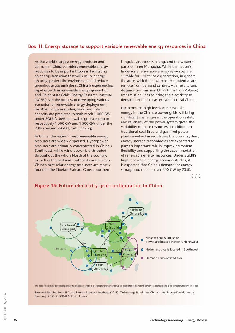
36 Technology Roadmap Energy storage
Box 11: Energy storage to support variable renewable energy resources in China
As the world’s largest energy producer and consumer, China considers renewable energy resources to be important tools in facilitating an energy transition that will ensure energy security, protect the environment and reduce greenhouse gas emissions. China is experiencing rapid growth in renewable energy generation, and China State Grid’s Energy Research Institute (SGERI) is in the process of developing various scenarios for renewable energy deployment for 2050. In these studies, wind and solar capacity are predicted to both reach 1 000 GW under SGERI’s 50% renewable grid scenario or respectively 1 500 GW and 1 300 GW under the 70% scenario. (SGERI, forthcoming)
In China, the nation’s best renewable energy resources are widely dispersed. Hydropower resources are primarily concentrated in China’s Southwest, while wind power is distributed throughout the whole North of the country, as well as the east and southeast coastal areas. China’s best solar energy resources are mostly found in the Tibetan Plateau, Gansu, northern
Ningxia, southern Xinjiang, and the western parts of Inner Mongolia. While the nation’s large-scale renewable energy resources are suitable for utility-scale generation, in general the areas with the most resource potential are remote from demand centres. As a result, long distance transmission UHV (Ultra High Voltage) transmission lines to bring the electricity to demand centers in eastern and central China.
Furthermore, high levels of renewable energy in the Chinese power grids will bring significant challenges in the operation safety and reliability of the power system given the variability of these resources. In addition to traditional coal-fired and gas-fired power plants involved in regulating the power system, energy storage technologies are expected to play an important role in improving system flexibility and supporting the accommodation of renewable energy resources. Under SGERI’s high renewable energy scenario studies, it is expected that China’s demand for energy storage could reach over 200 GW by 2050.
Figure 15: Future electricity grid configuration in China
Source: Modified from IEA and Energy Research Institute (2011), Technology Roadmap: China Wind Energy Development Roadmap 2050, OECD/IEA, Paris, France.
Demand concentrated area
Most of coal, wind, solar
power are located in North, Northwest
Hydro resource is located in SouthwestTibet gridCentral
China grid
Northwest
China grid
Northeast
China grid
Eastern
China grid
South
China grid
DC AC
North
China grid
This map is for illustrative purposes and is without prejudice to the status of or sovereignty over any territory, to the delimitation of international frontiers and boundaries, and to the name of any territory, city or area.
(.../...)
© O
EC
D/IE
A, 2
014

37
Box 11: Energy storage to support variable renewable energy resources in China (continued)
By the end of 2012, the accumulated energy storage capacity in China was about 18 GW, of which 57.4 MW was not pumped storage hydropower (PSH). In 2010 and 2011, the construction of demonstration projects achieved great progress with cumulative growth rates at 61% and 78%, respectively. Today, there are nearly 50 storage demonstration projects in the planning and operation stages in China. In these projects, major project applications include the support of wind power (53% of projects), distributed micro-grid projects (20%), and transmission and distribution grid support projects represents (7%).
PSH plants are currently considered the most mature and suitable energy storage technology for large-scale application in China’s power system. Generally, it is expected that PSH will maintain a dominant and important role in China’s energy storage markets as a support tool for an increasing proportion of renewable energy, ensuring the efficiency of conventional energy and promoting the safety and economy of power system. State Grid’s latest analysis expects that total PSH installed capacity will reach 54 GW in 2020 and 100 GW by 2030. As the number of high quality sites decreases for new PSH projects, development is expected to grow more slowly after 2030, to between 110 and 130 GW by 2050 (SGERI, 2014).
Electrochemical energy storage technologies have already been installed in Chinese wind farms for use in smoothing wind turbine output. In the Zhangbei wind, solar, storage and transmission demonstration project a 14 MW lithium iron phosphate battery system has been fully constructed. When the project is fully completed, it will have 500 MW wind, 100 MW photovoltaic and 110 MW of energy
storage. In the long run, given resource limitations and economic constraints, China is expected to introduce other mature energy storage technologies into the energy system to meet increasing flexibility needs. It is expected that electrochemical storage technology performance could achieve significant breakthroughs by 2020, resulting in decreased investment costs. With decreasing costs, large storage batteries can be integrated into the power grid for peak load management and frequency regulation applications.
Furthermore, user-side heat, cold and electricity storage could be considered a major tool for improving the energy storage capacity of the power system. Recent analysis by SGERI and the National Development and Reform Commission (NDRC) project that electric vehicles will become popular in China by 2050, potentially leading to a charging shock to the power grids that will need to be managed by policies or technical solutions (e.g. vehicle-to-grid management systems). Large-scale distributed energy storage devices installed on the demand side could also act as “virtual power plants” for meeting peak load. China’s expected solar thermal power plant development also introduces opportunities for molten salt thermal storage systems to play a significant role in the energy system.
Overall, in the short and medium term, it is more likely that new PSH plants and natural gas stations will be used to improve the flexibility of power system. If electrochemical energy storage technologies quickly mature, they could be used widely for large-scale applications to effectively support increasing amounts of renewable energy resources in the power system.
Note: this section was prepared by the State Grid Energy Research Institute.
Vision for deployment to 2050© O
EC
D/IE
A, 2
014

38 Technology Roadmap Energy storage
Energy storage technologies can have a valuable role to play in any energy system, including those with high and low proportions of variable renewable generation. In consultation with expert stakeholders, a series of actions and co-ordinating timelines were developed that will facilitate the accelerated deployment of these technologies in the energy system. This roadmap recommends a set of actions that broadly apply across energy storage
technologies as well as a number of technology-specific recommendations. The latter are focused on technologies that appear to be particularly well suited for future widespread deployment. Specific cost targets are not overly emphasised in these actions due to the high sensitivity to regulatory conditions and market design, as discussed later in this roadmap.
Energy storage technology development: actions and milestones
Actions spanning across technologies and applications
This roadmap recommends the following actions: Proposed timeline
Address data challenges for existing storage projects.
Create an accessible global dataset of energy storage technology project overviews, including information on system specifications, cost and performance with contextual details.
Concentrated effort in the short term (2014-17).
Quantify waste heat availability and opportunities, including details on waste heat quantity, quality, and location for both resources and potential demand.
Concentrated effort in the short term (2014-17).
Address data challenges for use in assessing future energy storage potential.
Build a comprehensive dataset of renewable generation production with high levels of granularity to allow for assessment across a wide range of energy storage technology applications throughout the year.
Concentrated effort in the short term (2014-20).
Assess global potential for energy storage deployment in the context of the ETP 2DS vision (technology-independent evaluation).
Longer-term effort (2020-30) after compilation of
necessary datasets.
Quantify distributed energy storage potential in buildings, e.g. domestic hot water heaters, commercial refrigeration centres.
Concentrated effort in the short term (2014-20).
Establish international and national data co-operation to foster energy storage research, monitor progress and assess the R&D bottlenecks.
2018
Support research, development and demonstration (RD&D) projects that incorporate the use of both electricity and thermal energy storage (i.e. hybrid systems) to maximise resource use efficiency, with emphasis on optimising the location/application factor.
Medium-term effort (2020-50).
Support R&D efforts focused on 1) technology breakthroughs in high-temperature thermal storage systems and for scalable battery technologies and 2) storage systems that optimise the performance of the energy system and facilitate the integration of renewable energy resources.
Concentrated effort from 2014 to 2035.
Identify specific applications and combination of applications that are particularly suited for thermochemical storage system (i.e. high cycles per year).
Medium-term effort (2020-35)
© O
EC
D/IE
A, 2
014

39Energy storage technology development: actions and milestones
Address data challenges for existing storage projects
Energy storage technologies can be valuable assets throughout the energy system, but quantifying the potential for energy storage is challenging due to current global dataset limitations. Currently accessible global datasets do not include an exhaustive list of projects or project details sufficient to establish an accurate baseline. For the storage projects that are present in existing lists, the following information is not consistently included:
z power (MW) and storage capacity (total MWh charge/discharge)
z information on relevant government and policy landscapes, funding schemes, realised fixed and variable costs, execution details, and operating constraints
z details regarding quantity, quality, and location of both the supply resources and corresponding demand for waste heat.18
To encourage the accelerated deployment of electricity and thermal energy storage technologies, governments should support the development of an accessible global database of existing electricity and thermal storage projects that includes the above details. This effort could partner with existing efforts.19 Once this dataset is established, it should be routinely updated as new data become available.
Assess global energy storage technology potential
Once a baseline is effectively established, global energy storage technology potential assessments can be completed beyond a technical-potential level. However, further difficulties hinder attempts at quantifying energy storage potential by application. Primary challenges include a lack of easily accessible renewable energy production, heating and cooling demand curves, and waste heat availability datasets with sufficient levels of granularity (sub-hourly level) reflecting observed system behaviour across long time frames. Access to these types of datasets will allow for the detailed modelling and quantification of the total energy storage potential (technology-independent) across the energy system.
18. In some regions, domestic electric water heaters are well deployed and used as thermal storage for load leveling purposes, but total capacity and potential are not captured in global datasets.
19. For example, the US Department of Energy’s Global Energy Storage Database.
While these more granular datasets are being built and compiled, global technical potential assessments should be completed. For capital-intensive storage projects including PSH, CAES, and UTES technical constraints and geographical requirements should be evaluated. Of particular interest here is new information related to CAES technologies, which indicates that previous siting evaluations may have drastically overestimated the number of naturally existing caverns suitable for this application (Denholm, 2013).
Separate efforts should be made to quantify the current distributed energy storage potential in existing infrastructure. Commercial refrigeration facilities and domestic hot water heaters in particular represent significant thermal energy storage potential. According to research to date, the former could be an appealing option for storing excess energy from renewable energy resources. The latter could be a valuable load-shedding resource as is already seen in France, where residential electric water heaters are responsible for an almost 5 GW peak reduction in the winter months. This reduction is made possible through a combination of peak-pricing tariffs, a remote start/stop system for electric water heaters, and significant consumer awareness campaigns (Box 7). In Japan and China, ice and cold-water storage systems are already reducing peak energy demand from buildings.
In quantifying these potentials, attention should be paid to other technologies that can supply the same energy or power services. For example, larger planning areas, flexible thermal generation, and new transmission and distribution infrastructure can be used for many of the same applications. Further, as energy storage technologies will not operate with 100% efficiency, these losses should be included in any calculations.
International and national data co-operation can foster electricity storage research, monitor progress and assess the R&D bottlenecks. Major discrepancies in current and future storage technology costs show the significant uncertainty around future storage R&D progress, and rapid technology development shows the need for industry involvement.
© O
EC
D/IE
A, 2
014
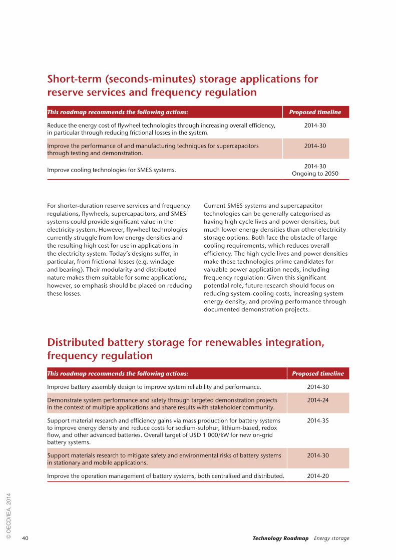
40 Technology Roadmap Energy storage
For shorter-duration reserve services and frequency regulations, flywheels, supercapacitors, and SMES systems could provide significant value in the electricity system. However, flywheel technologies currently struggle from low energy densities and the resulting high cost for use in applications in the electricity system. Today’s designs suffer, in particular, from frictional losses (e.g. windage and bearing). Their modularity and distributed nature makes them suitable for some applications, however, so emphasis should be placed on reducing these losses.
Current SMES systems and supercapacitor technologies can be generally categorised as having high cycle lives and power densities, but much lower energy densities than other electricity storage options. Both face the obstacle of large cooling requirements, which reduces overall efficiency. The high cycle lives and power densities make these technologies prime candidates for valuable power application needs, including frequency regulation. Given this significant potential role, future research should focus on reducing system-cooling costs, increasing system energy density, and proving performance through documented demonstration projects.
Short-term (seconds-minutes) storage applications for reserve services and frequency regulation
This roadmap recommends the following actions: Proposed timeline
Reduce the energy cost of flywheel technologies through increasing overall efficiency, in particular through reducing frictional losses in the system.
2014-30
Improve the performance of and manufacturing techniques for supercapacitors through testing and demonstration.
2014-30
Improve cooling technologies for SMES systems. 2014-30Ongoing to 2050
Distributed battery storage for renewables integration, frequency regulation
This roadmap recommends the following actions: Proposed timeline
Improve battery assembly design to improve system reliability and performance. 2014-30
Demonstrate system performance and safety through targeted demonstration projects in the context of multiple applications and share results with stakeholder community.
2014-24
Support material research and efficiency gains via mass production for battery systems to improve energy density and reduce costs for sodium-sulphur, lithium-based, redox flow, and other advanced batteries. Overall target of USD 1 000/kW for new on-grid battery systems.
2014-35
Support materials research to mitigate safety and environmental risks of battery systems in stationary and mobile applications.
2014-30
Improve the operation management of battery systems, both centralised and distributed. 2014-20
© O
EC
D/IE
A, 2
014
41
The scalability of battery storage systems makes them well suited to a large array of applications and locations in the energy system. Today, batteries are cost competitive or near-competitive for many off-grid and remote community applications. However, today’s battery systems struggle to realise widespread deployment for on-grid applications due to relatively high costs as well as questions related to the performance (lifespan, cycle performance) and the perceived safety risks associated with these systems. While the price of some battery technologies has rapidly declined, there is still a distance to go before they can achieve widespread deployment (EVI and IEA, 2013).
Current battery research is focused on new materials and chemical compositions that would enhance energy density and mitigate safety and environmental issues. In particular, manufacturing challenges with the assembly systems contribute to total system costs and introduce a significant opportunity area. At a minimum, these battery systems must achieve cost reductions to USD 1 000 per kilowatt (kW) by 2050 to achieve the deployment levels in the “breakthrough” scenario
presented in this roadmap. However, it would be highly beneficial if this cost reduction target could be achieved earlier (by 2035).
Other current barriers include a lack of accessible system performance data with a contextualised cost and benefits analysis and a lack of widespread experience in managing these systems in the stakeholder community, as well as perceived safety concerns for some battery technologies. In the specific case of lithium ion batteries, significant cost reductions have been achieved, but additional reductions are needed to achieve widespread competitiveness. Demand for these batteries for EVs may provide an opportunity for accelerated cost reductions via mass production. Furthermore, EV batteries might be reused, finding second lives in stationary applications before ultimately being recycled. However, it is equally true that the weight and size considerations that play a primary role in EV battery technology development are not as important in stationary applications, so reductions in battery costs for EVs may not directly lead to increasing stationary use.
Box 12: Rare earth elements
Rare earth elements (REEs) are widely used in many energy storage technologies. Supply challenges for some of these materials (in particular dysprosium, neodymium, terbium, europium, and yttrium) result in a risk of supply interruptions in the short-term. In the longer term, efficient recycling of these materials can reduce the environmental impacts of REE mining and processing, and reduce the risk of supply disruptions from countries with large reserves to those with high demand. Recently,
China has tightened its REE supply and some countries, including the United States, have instituted centralised efforts to recycle these materials (US DOE, 2012). Many countries already have successful battery recycling programmes to recover usable REEs and to reduce negative environmental impacts. For example, 96% of lead-acid batteries are recycled each year. Furthermore, new lead-acid batteries in the United States are made from 60% to 80% recycled materials (US EPA, 2012).
Energy storage technology development: actions and milestones© O
EC
D/IE
A, 2
014

42 Technology Roadmap Energy storage
In addition to the battery technology recommendations presented in the previous section, this roadmap recommends additional actions for technologies that can support long-term storage applications. PSH and CAES technologies have significant potential as both bulk storage and to supply other services in the electricity grid. In Europe, it is estimated that PSH capacity could be increased by up to 10 times the current volume. (Gimeno-Gutiérrez and Lacal-Arántegui, 2013) Unfortunately, these technologies struggle from the high upfront investment costs due to large project sizes and – in some cases – geographic requirements that can further increase upfront costs.
Given the large potential role for these technologies, it is crucial that assessments be completed to identify suitable sites for new installations. In these evaluations, emphasis should be placed on seawater PSH and underground PSH in additional to conventional dam and run-of-river designs (IEA, 2012).20 Underground PSH refers to systems where a well is drilled into underground reservoirs, allowing water to be pumped up into higher reservoirs (either other underground reservoirs or surface-level, man-made holding areas). This technology has shown promise in small to medium sized storage systems.
20. Run-of-river designs for hydropower facilities function similarly Run-of-river designs for hydropower facilities function similarly to conventional plants, except little or no water storage (reservoir) is incorporated.
In the case of PSH, with its current dominance in global long-term electricity storage, the large number of existing constant-speed storage systems also provides the opportunity to increase storage capabilities without the need for new facilities (IEA, 2012). This potential could be realised through the transformation of existing facilities into variable-speed systems where significant opportunities exist. These facilities could then better supply electricity grid support services, shortening the payback period for these large investments. The potential for these retrofits and the associated estimated costs should be identified and then completed as is seen fit.
For CAES technologies, new design proposals have the potential to reach efficiencies of up to 70% primarily through reducing natural gas use. However, these technologies have not been deployed at scale.21
21. See technical annex for more detail on these energy storage See technical annex for more detail on these energy storage technologies. www.iea.org/publications/freepublications/publication/name,36573,en.html.
Long-term (hours-seasons) storage applications for arbitrage, load following, and other grid services
This roadmap recommends the following actions: Proposed timeline
Assess and catalogue potential PSH and CAES sites and estimated costs. For PSH, this assessment should include pump-back, off-stream, and closed-loop, land-based and marine potential.
2014-20
Assess potential and costs of transforming existing constant-speed PSH into variable-speed, allowing these plants to provide additional ancillary services in both charging and discharging modes.
2014-20
Investigate the potential to improve total efficiency and flexibility in existing PSH facilities. Complete retrofits on systems that provide significant opportunity.
2014-20 (assess potential), 2020-35 (complete retrofits)
Improve the storage efficiency of CAES systems to approach 70%, particularly through improvements in compression (turbine) efficiency and adiabatic CAES project development.
2014-35
© O
EC
D/IE
A, 2
014
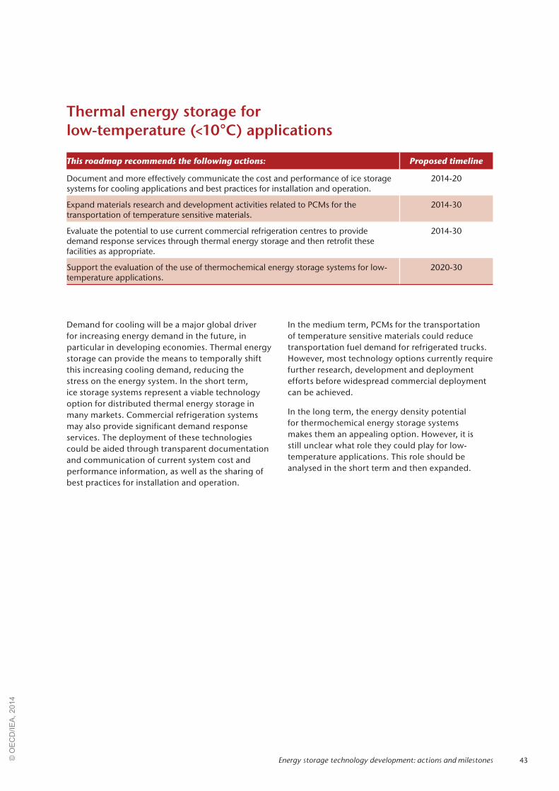
43
Demand for cooling will be a major global driver for increasing energy demand in the future, in particular in developing economies. Thermal energy storage can provide the means to temporally shift this increasing cooling demand, reducing the stress on the energy system. In the short term, ice storage systems represent a viable technology option for distributed thermal energy storage in many markets. Commercial refrigeration systems may also provide significant demand response services. The deployment of these technologies could be aided through transparent documentation and communication of current system cost and performance information, as well as the sharing of best practices for installation and operation.
In the medium term, PCMs for the transportation of temperature sensitive materials could reduce transportation fuel demand for refrigerated trucks. However, most technology options currently require further research, development and deployment efforts before widespread commercial deployment can be achieved.
In the long term, the energy density potential for thermochemical energy storage systems makes them an appealing option. However, it is still unclear what role they could play for low-temperature applications. This role should be analysed in the short term and then expanded.
Thermal energy storage for low-temperature (<10°C) applications
This roadmap recommends the following actions: Proposed timeline
Document and more effectively communicate the cost and performance of ice storage systems for cooling applications and best practices for installation and operation.
2014-20
Expand materials research and development activities related to PCMs for the transportation of temperature sensitive materials.
2014-30
Evaluate the potential to use current commercial refrigeration centres to provide demand response services through thermal energy storage and then retrofit these facilities as appropriate.
2014-30
Support the evaluation of the use of thermochemical energy storage systems for low-temperature applications.
2020-30
Energy storage technology development: actions and milestones© O
EC
D/IE
A, 2
014
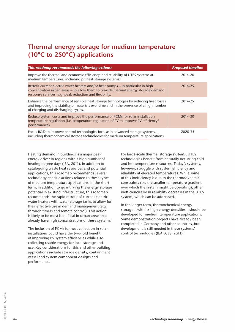
44 Technology Roadmap Energy storage
Thermal energy storage for medium temperature (10°C to 250°C) applications
This roadmap recommends the following actions: Proposed timeline
Improve the thermal and economic efficiency, and reliability of UTES systems at medium temperatures, including pit heat storage systems.
2014-20
Retrofit current electric water heaters and/or heat pumps – in particular in high concentration urban areas – to allow them to provide thermal energy storage demand response services, e.g. peak reduction and flexibility.
2014-25
Enhance the performance of sensible heat storage technologies by reducing heat losses and improving the stability of materials over time and in the presence of a high number of charging and discharging cycles.
2014-25
Reduce system costs and improve the performance of PCMs for solar installation temperature regulation (i.e. temperature regulation of PV to improve PV efficiency/performance).
2014-30
Focus R&D to improve control technologies for use in advanced storage systems, including thermochemical storage technologies for medium temperature applications.
2020-35
Heating demand in buildings is a major peak energy driver in regions with a high number of heating degree days (IEA, 2011). In addition to cataloguing waste heat resources and potential applications, this roadmap recommends several technology-specific actions related to these types of medium temperature applications. In the short term, in addition to quantifying the energy storage potential in existing infrastructure, this roadmap recommends the rapid retrofit of current electric water heaters with water storage tanks to allow for their effective use in demand management (e.g. through timers and remote control). This action is likely to be most beneficial in urban areas that already have high concentrations of these systems.
The inclusion of PCMs for heat collection in solar installations could have the two-fold benefit of improving PV system efficiencies while also collecting usable energy for local storage and use. Key considerations for this and other building applications include storage density, containment vessel and system component designs and performance.
For large-scale thermal storage systems, UTES technologies benefit from naturally occurring cold and hot temperature resources. Today’s systems, however, struggle with system efficiency and reliability at elevated temperatures. While some of this inefficiency is due to the thermodynamic constraints (i.e. the smaller temperature gradient over which the system might be operating), other inefficiencies lie in reliability decreases in the UTES system, which can be addressed.
In the longer term, thermochemical energy storage – with its high energy densities – should be developed for medium temperature applications. Some demonstration projects have already been completed in Germany and other countries, but development is still needed in these systems’ control technologies (IEA ECES, 2011).
© O
EC
D/IE
A, 2
014

45
In thermal energy storage, one prominent opportunity lies in improving the storage materials used in CSP applications. Today’s molten salt mixtures remain stable at temperatures above 400°C, providing an advantage compared to oils used for similar applications. However, these mixtures typically solidify at temperatures below the 200°C to 250 °C range, resulting in significant energy requirements during the night-time to prevent damage from solidification when heat is not being collected. If these salts are allowed to solidify, serious mechanical problems will result. Therefore, preventing solidification at temperatures below 200°C represents a prime efficiency opportunity and could significantly reduce the costs of thermal storage in CSP facilities.
The high long-term potential for thermochemical energy storage to provide high-density, low-cost, and high-cycle energy storage makes it an attractive area for R&D. Currently, major challenges to thermochemical storage systems include material stability and containment, as well as the development of effective control technology. Once these issues are resolved, it will be easier to identify the ideal applications for these technologies; over the next decade, emphasis should be placed on materials research. Subsequently, emphasis should shift to rapidly applying these designs in demonstration projects (IEA ECES, 2011).
Advances in geothermal R&D activities could lead to improvements in system concepts and operation of UTES to overcome hydrogeological constraints and to prevent scaling and corrosion at high temperatures (EC, 2013).
Thermal energy storage for high-temperature (>250°C) applications
This roadmap recommends the following actions: Proposed timeline
Improve system concepts and operational characteristics of UTES systems in different geological conditions.
2014-25
Develop molten salts (or similar thermal energy storage materials) with lower melting temperatures, while maintaining their stability at higher temperatures for CSP applications to improve system efficiency.
2014-30
Focus R&D to improve the material stability and associated control technology of thermochemical storage systems for high-temperature applications (e.g. develop new containment vessels that perform well under significant temperature changes with peak temperatures exceeding 250°C).
2014-30
Improve the containment vessels and associated equipment used in PCM storage systems. 2014-35
Identify the potential environmental impacts of high-temperature UTES systems (e.g. impacts on geology, water quality) and ways to mitigate these impacts.
2020-30
Energy storage technology development: actions and milestones© O
EC
D/IE
A, 2
014

46 Technology Roadmap Energy storage
There are several drivers that support increasing use of energy storage technologies, including the movement toward decarbonisation, increasing energy access, greater emphasis on energy security, aging energy system infrastructure, and an emphasis on decentralised energy production, in part due to rapidly declining solar PV costs. At the same time, many factors influence the deployment of energy storage beyond technology cost and performance.
The widespread deployment of these technologies is particularly dependent on achieving acceptable cost recovery. Current policy environments and market conditions often cloud the cost of energy services, creating significant price distortions (e.g. by requiring generators to also supply power services without additional compensation, obscuring the cost of these additional services). In liberalised electricity markets, energy storage cannot receive direct payments for many of the benefits it provides (e.g. transmission investment deferral).
Unless compensation for energy storage system services is provided – or reliable cost recovery mechanisms are put in place – high levels of deployment will be difficult to achieve and storage technologies when competing with other options for system flexibility. A key to achieving widespread storage technology deployment is enabling compensation for the multiple services performed across the energy system. A patchwork approach to creating an energy storage market will not be able to capture the full value of energy storage technologies.
In unbundled electricity systems in particular, storage technologies frequently do not fit naturally into existing regulatory frameworks, as they provide value across different portions of the market (i.e. a single technology supports both the supply and demand sides, or transmission and distribution). Moreover, the current economic climate makes it difficult for organisations to invest in infrastructure projects, including energy storage. It also amplifies risk-averse inclinations of utilities, as well as existing inertia toward traditional supply technologies and grid management practices.
These factors emphasise the need for a focus on compensation as a function of the service provided by an energy system technology (e.g. payment based on the value of reliability, power quality, energy security and efficiency gains). They also signify areas where governments can actively support the accelerated deployment of energy storage.
Many governments have already acted publically in support of energy storage project development, through efforts such as direct financial support of demonstration projects, comprehensive market transformations, and mandates for energy storage projects (Table 9). Nonetheless, while many governments have made strides in supporting widespread adoption of energy storage technologies, there is still a great distance to go in accelerating their deployment.
These actions are interesting case studies for identifying global recommendations for policy actions and international collaboration. In particular, recent action in the United States reveals how a market-based approach can accelerate energy storage technology deployment on a large scale. In California, the state’s Public Utility Commission has recently mandated the procurement of energy storage technologies. In 2013, Southern California Edison requested bids for 50 MW of new storage projects for the Los Angeles region and received more than 500 formal proposes. The German government’s support of small-scale storage in support of distributed solar PV resources provides insight on the added value of distributed storage in a high renewable penetration environment. Japan’s recent emphasis on time-shifting large amounts of energy demand using storage technologies also provides an interesting viewpoint on the potential for storage as a demand response tool.
Policy, finance, and international collaboration: actions and milestones
© O
EC
D/IE
A, 2
014
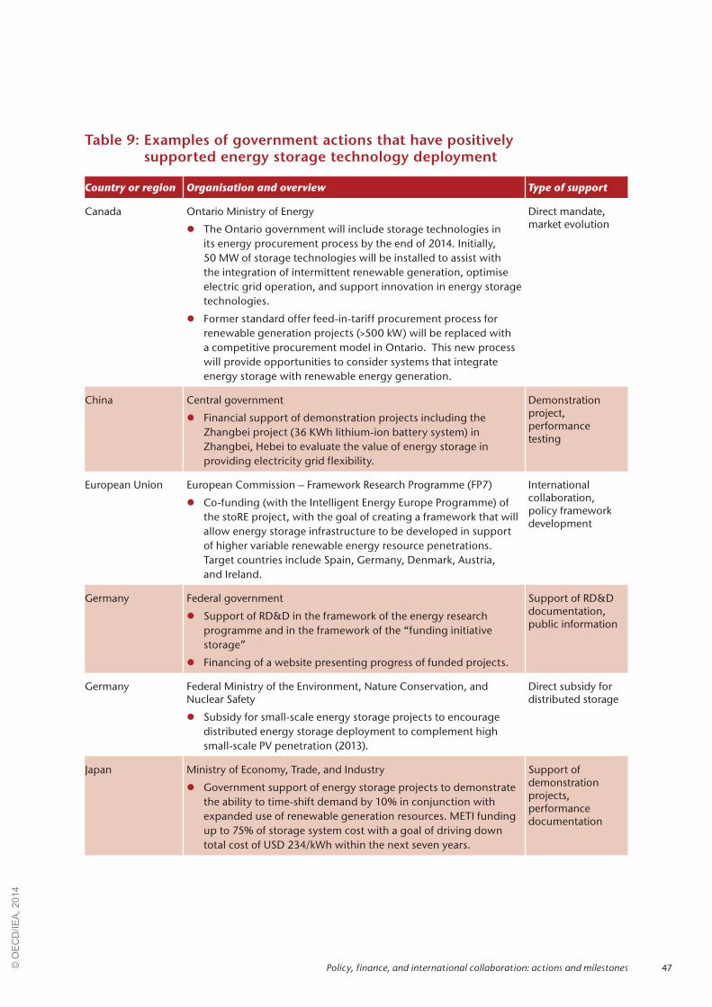
47
Table 9: Examples of government actions that have positively supported energy storage technology deployment
Country or region Organisation and overview Type of support
Canada Ontario Ministry of Energy
z The Ontario government will include storage technologies in its energy procurement process by the end of 2014. Initially, 50 MW of storage technologies will be installed to assist with the integration of intermittent renewable generation, optimise electric grid operation, and support innovation in energy storage technologies.
z Former standard offer feed-in-tariff procurement process for renewable generation projects (>500 kW) will be replaced with a competitive procurement model in Ontario. This new process will provide opportunities to consider systems that integrate energy storage with renewable energy generation.
Direct mandate, market evolution
China Central government
z Financial support of demonstration projects including the Zhangbei project (36 KWh lithium-ion battery system) in Zhangbei, Hebei to evaluate the value of energy storage in providing electricity grid flexibility.
Demonstration project, performance testing
European Union European Commission – Framework Research Programme (FP7)
z Co-funding (with the Intelligent Energy Europe Programme) of the stoRE project, with the goal of creating a framework that will allow energy storage infrastructure to be developed in support of higher variable renewable energy resource penetrations. Target countries include Spain, Germany, Denmark, Austria, and Ireland.
International collaboration, policy framework development
Germany Federal government
z Support of RD&D in the framework of the energy research programme and in the framework of the “funding initiative storage”
z Financing of a website presenting progress of funded projects.
Support of RD&D documentation, public information
Germany Federal Ministry of the Environment, Nature Conservation, and Nuclear Safety
z Subsidy for small-scale energy storage projects to encourage distributed energy storage deployment to complement high small-scale PV penetration (2013).
Direct subsidy for distributed storage
Japan Ministry of Economy, Trade, and Industry
z Government support of energy storage projects to demonstrate the ability to time-shift demand by 10% in conjunction with expanded use of renewable generation resources. METI funding up to 75% of storage system cost with a goal of driving down total cost of USD 234/kWh within the next seven years.
Support of demonstration projects, performance documentation
Policy, finance, and international collaboration: actions and milestones© O
EC
D/IE
A, 2
014
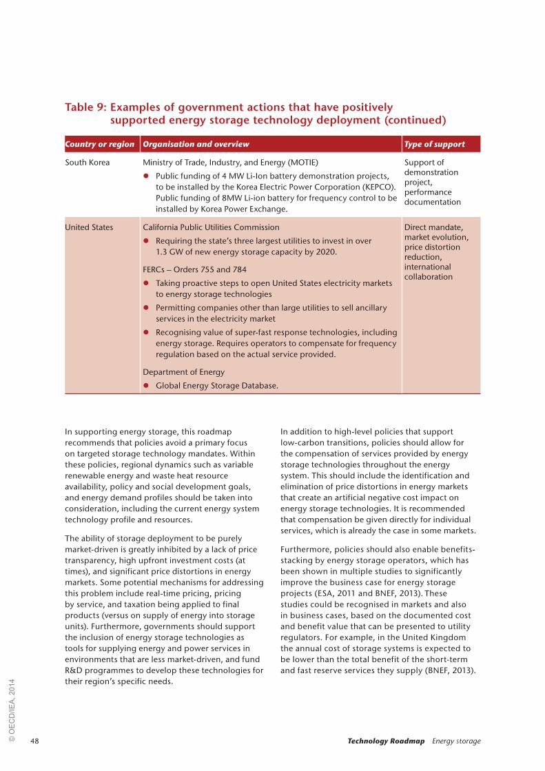
48 Technology Roadmap Energy storage
In supporting energy storage, this roadmap recommends that policies avoid a primary focus on targeted storage technology mandates. Within these policies, regional dynamics such as variable renewable energy and waste heat resource availability, policy and social development goals, and energy demand profiles should be taken into consideration, including the current energy system technology profile and resources.
The ability of storage deployment to be purely market-driven is greatly inhibited by a lack of price transparency, high upfront investment costs (at times), and significant price distortions in energy markets. Some potential mechanisms for addressing this problem include real-time pricing, pricing by service, and taxation being applied to final products (versus on supply of energy into storage units). Furthermore, governments should support the inclusion of energy storage technologies as tools for supplying energy and power services in environments that are less market-driven, and fund R&D programmes to develop these technologies for their region’s specific needs.
In addition to high-level policies that support low-carbon transitions, policies should allow for the compensation of services provided by energy storage technologies throughout the energy system. This should include the identification and elimination of price distortions in energy markets that create an artificial negative cost impact on energy storage technologies. It is recommended that compensation be given directly for individual services, which is already the case in some markets.
Furthermore, policies should also enable benefits-stacking by energy storage operators, which has been shown in multiple studies to significantly improve the business case for energy storage projects (ESA, 2011 and BNEF, 2013). These studies could be recognised in markets and also in business cases, based on the documented cost and benefit value that can be presented to utility regulators. For example, in the United Kingdom the annual cost of storage systems is expected to be lower than the total benefit of the short-term and fast reserve services they supply (BNEF, 2013).
Country or region Organisation and overview Type of support
South Korea Ministry of Trade, Industry, and Energy (MOTIE)
z Public funding of 4 MW Li-Ion battery demonstration projects, to be installed by the Korea Electric Power Corporation (KEPCO). Public funding of 8MW Li-ion battery for frequency control to be installed by Korea Power Exchange.
Support of demonstration project, performance documentation
United States California Public Utilities Commission
z Requiring the state’s three largest utilities to invest in over 1.3 GW of new energy storage capacity by 2020.
FERCs – Orders 755 and 784
z Taking proactive steps to open United States electricity markets to energy storage technologies
z Permitting companies other than large utilities to sell ancillary services in the electricity market
z Recognising value of super-fast response technologies, including energy storage. Requires operators to compensate for frequency regulation based on the actual service provided.
Department of Energy
z Global Energy Storage Database.
Direct mandate, market evolution, price distortion reduction, international collaboration
Table 9: Examples of government actions that have positively supported energy storage technology deployment (continued)
© O
EC
D/IE
A, 2
014

49Policy, finance, and international collaboration: actions and milestones
These studies can also be used for the benefit of systems that are less market-driven, quantitatively justifying policies allowing for the addition of energy storage technologies.
Recent action in the United States, under FERC Orders 755 and 784, provide evidence of how access to ancillary service markets can positively influence storage project proposal economics. However, it is yet to be seen if these efforts will be sufficient to support the entire suite of electricity and thermal storage technologies currently available to provide energy system support services.
In the shorter term, policies should encourage energy storage deployment in off-grid and remote communities where energy storage technologies are already broadly competitive or near-competitive. In these cases, third-party verification of energy storage project performance could become prime case studies for later implementation in other geographies. Furthermore, off-grid areas in developing economies provide an additional opportunity for energy storage demonstration projects and case study development. These locations also introduce the opportunity for incremental gains through increased production values.
For existing centralised storage facilities, efforts should be made to increase their efficiency and flexibility, improving their potential to support increasing levels of variable renewable generation and to optimise energy exchanges within both the electricity grid and dedicated heat networks. For existing demand-side infrastructure, governments
should support the inventorying and utilisation of existing – primarily thermal – distributed storage capacity. A common drawback of these systems is the currently limited feedback to users regarding the system’s performance. Improved statistics and efficiency labelling schemes for energy storage could increase storage deployment and use. For example, in the use of residential hot water heaters and commercial refrigeration centres for demand response, better matching of supply and demand curves could result in significant efficiency (and carbon emissions reduction) gains.
In the longer term, policies should be geared toward incentivising storage technologies based on the applications they are used for in the energy system. The development of breakthrough energy storage technologies should also be supported by policies that endorse financing of innovative research, development, and demonstration projects. While specific technology actions were previously discussed, it is noted here that governments can play a key role in the collection and dissemination of lessons learned from demonstration projects. These efforts may expand upon those already initiated by other government organisations.22
22. For example, the US Department of Energy’s Global Energy Storage Database.
Policy and regulatory frameworks
This roadmap recommends that the following actions be taken: Milestone
Eliminate price distortions and increase price transparency for power generation and heat production, e.g. time-of-use pricing schemes, pay-for-services (heating, cooling, quick response, etc.) models.
2020
Enable benefits-stacking for energy storage systems. 2020
Government support of energy storage use in off-grid and remote communities. 2025
Support of the rapid retrofit of existing energy storage facilities to increase efficiency and flexibility, where these retrofits appear warranted.
2030
Inclusion of energy storage technologies as options for supplying energy and power services, and support for their continued development through government-funded R&D programmes.
2030
© O
EC
D/IE
A, 2
014

50 Technology Roadmap Energy storage
While policy and regulatory reform can create a more attractive environment for energy storage investments, further action is needed to incentivise widespread investment. Efforts should especially be made to clarify ownership structures in ways that enable energy storage technologies to be used for a wide array of applications over time.
Furthermore, both large- and small-scale storage systems would benefit from more transparent means for securing financing. For large-scale projects, the process of securing financing should be streamlined, with requirements for the information needed to successfully support financing attempts. For small-scale (distributed) storage resources, there would be many benefits from co-financing opportunities for new generation resources with integrated storage (e.g. residential PV systems with onsite battery storage, or wall heaters with thermal storage).
Easy entry into, and exit from, energy markets is also a key to incentivising investment, allowing new companies to supply energy and power
services in the market. This ease will allow for new technologies to progress more rapidly across development “valleys of death” – to move from the lab bench to commercial markets. On the demand side of the energy system, the adoption of tariff structures or programmes capable of revealing the value of particular services might help support distributed energy storage systems (e.g. in homes and office buildings) and help catalyse customer adoption and use of these technologies.
Another key component in moving suitable technologies more quickly from laboratory to widespread commercial deployment lies in targeted financial support in demonstration projects, as well as risk guarantee schemes (in particular for large-scale storage projects). By supporting key demonstration projects, governments can not only help move technologies along the development path but also gain useful data and knowledge of best practices that can be applied in widespread deployment efforts.
Incentivising investment
This roadmap recommends that the following actions be taken: Milestone
Facilitate entry into, and exit from, energy markets from the supply through demand portions of the energy system: e.g. through ancillary service markets and tariff structures to support distributed energy storage systems.
2015
Clarify energy storage’s role in the energy system, e.g. through defining ownership structures and ownership eligibility.
2018
Streamline the financing process for new large-scale storage systems, with clear guidelines on documentation requirements.
2018
Incentivise the co-financing of distributed electricity generation technologies with integrated storage after assessing the risks and benefits of this approach.
2020
Targeted support for energy storage demonstration projects and financial support of early movers for new commercial-scale projects (e.g. through risk guarantee schemes).
2025
Planning and permitting
This roadmap recommends that the following actions be taken: Milestone
Develop a widely accessible clearinghouse for energy storage project information and other data needed to support project proposal evaluations.
2020 (existing), ongoing to 2050
(new projects)
Streamline the siting and permitting process for new centralised energy storage projects, in particular for UTES systems.
2025
© O
EC
D/IE
A, 2
014

51
Two primary barriers exist to widespread energy storage technology deployment in terms of project planning and permitting. First, the lack of a widely accessible clearinghouse for energy storage project information inhibits project proposal development. This information should go beyond technical performance and cost data to include best practices and operational lessons learned. Furthermore, today’s siting and permitting processes for new energy storage projects can be quite long and
cumbersome. Similar to energy supply infrastructure permitting processes, this complexity adds significantly to total project costs in many cases. Current regulatory barriers to increased use of groundwater for UTES systems should be evaluated and updated. This problem should be addressed through a streamlining of siting and permitting processes to provide clarity in the expectations for new energy storage system projects.
Training and public engagement
This roadmap recommends that the following actions be taken: Milestone
Develop improved workforce training programmes with customised course content pertaining to energy storage technologies.
2018
Further develop international standards and testing programmes to document safety and performance of energy storage technologies.
2018
Develop and implement programmes to increase the utilisation of distributed demand-side energy storage capacity (i.e. residential water heaters with timers and remote control capabilities to shift demand from peak to off-peak periods).
2020
Some energy storage technologies are covered by recognised international standards, which simplify system procurement, installation and operation. Other technologies (e.g. batteries) may be subject to inappropriate standards, because the standard-making process has not kept up with the rate of technical development. For technologies that are on the brink of commercial viability, this roadmap recommends widespread support through the development of standards and operation protocols,23 workforce training programmes, performance and safety testing, and consumer awareness programmes. Combined, these actions will help to overcome NIMBYism and other consumer acceptance hurdles. These international standards should be established in a manner that allows for easy updating with technology advancements.
Performance and safety testing can particularly help in overcoming both supply-side and demand-side consumer acceptance of storage technologies, as well as improve access to financing. Actions should be taken to test and document performance and safety records for energy storage technologies as they reach commercial maturity. Furthermore, for
23. by organisations including the International Organization for Standardization (ISO).
storage technologies with high levels of deployment potential, any safety risks that are identified in these testing procedures should lead directly to targeted R&D efforts.
For distributed demand-side energy storage capacity in existing infrastructure (e.g. residential hot water heaters), experiences in France (among other countries) have shown how consumer awareness programmes can significantly improve adoption rates. Combined with the previous recommendation to eliminate energy market price distortions, consumer awareness campaigns will help increase utilisation factors for these storage assets.
Policy, finance, and international collaboration: actions and milestones© O
EC
D/IE
A, 2
014

52 Technology Roadmap Energy storage
In a global transition to a decarbonised energy system, many opportunities exist for international collaboration. Countries and regions with significant experience evaluating energy storage technologies can provide guidance for new market participants. Developing economies could provide opportunities for the development of innovation “free” zones (i.e. “free” of non-technical barriers), where new technologies may be tested in the absence of distorting policies and other energy system complexities. However, market exposure is highly needed for energy storage technologies to achieve widespread deployment. Demonstration projects should therefore not be limited to these “free” zones, as described in the previous section.
Perhaps most significant is the opportunity for knowledge sharing through the development of an international energy storage project database and production databases for energy supply and demand curves. This type of collaborative effort would greatly enhance technical and market
analysis for new storage technology proposals, and if continually updated over time, opportunities for research and future development will present themselves. The US Department of Energy has made significant progress in establishing such a database with their “Global Energy Storage Database” website, but more input from other countries is needed.
In addition, several multilateral initiatives have emerged in recent years to facilitate collaboration on storage technology, including the ECES IA. In the European Union, the EASE and the European Technology Platform on Renewable Heating and Cooling are examples of collaborative initiatives that are striving to encourage accelerated energy storage technology development and deployment.
International collaboration
This roadmap recommends that the following actions be taken: Milestone
Designate innovation “free” zones to facilitate the testing of storage technologies in the absence of complex markets and policy structures.
2020
Promote knowledge sharing through the development of an international energy storage project database and production databases for energy supply and demand curves with high levels of granularity.
2030 (ongoing to 2050)
© O
EC
D/IE
A, 2
014
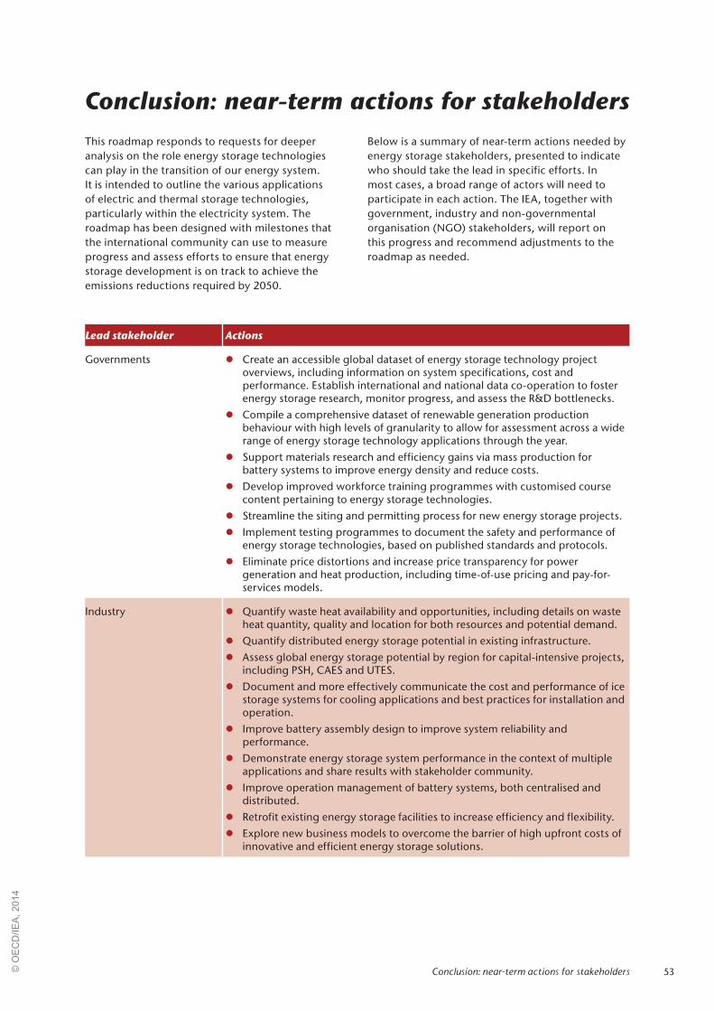
53
Conclusion: near-term actions for stakeholdersThis roadmap responds to requests for deeper analysis on the role energy storage technologies can play in the transition of our energy system. It is intended to outline the various applications of electric and thermal storage technologies, particularly within the electricity system. The roadmap has been designed with milestones that the international community can use to measure progress and assess efforts to ensure that energy storage development is on track to achieve the emissions reductions required by 2050.
Below is a summary of near-term actions needed by energy storage stakeholders, presented to indicate who should take the lead in specific efforts. In most cases, a broad range of actors will need to participate in each action. The IEA, together with government, industry and non-governmental organisation (NGO) stakeholders, will report on this progress and recommend adjustments to the roadmap as needed.
Lead stakeholder Actions
Governments z Create an accessible global dataset of energy storage technology project overviews, including information on system specifications, cost and performance. Establish international and national data co-operation to foster energy storage research, monitor progress, and assess the R&D bottlenecks.
z Compile a comprehensive dataset of renewable generation production behaviour with high levels of granularity to allow for assessment across a wide range of energy storage technology applications through the year.
z Support materials research and efficiency gains via mass production for battery systems to improve energy density and reduce costs.
z Develop improved workforce training programmes with customised course content pertaining to energy storage technologies.
z Streamline the siting and permitting process for new energy storage projects.
z Implement testing programmes to document the safety and performance of energy storage technologies, based on published standards and protocols.
z Eliminate price distortions and increase price transparency for power generation and heat production, including time-of-use pricing and pay-for-services models.
Industry z Quantify waste heat availability and opportunities, including details on waste heat quantity, quality and location for both resources and potential demand.
z Quantify distributed energy storage potential in existing infrastructure.
z Assess global energy storage potential by region for capital-intensive projects, including PSH, CAES and UTES.
z Document and more effectively communicate the cost and performance of ice storage systems for cooling applications and best practices for installation and operation.
z Improve battery assembly design to improve system reliability and performance.
z Demonstrate energy storage system performance in the context of multiple applications and share results with stakeholder community.
z Improve operation management of battery systems, both centralised and distributed.
z Retrofit existing energy storage facilities to increase efficiency and flexibility.
z Explore new business models to overcome the barrier of high upfront costs of innovative and efficient energy storage solutions.
Conclusion: near-term actions for stakeholders© O
EC
D/IE
A, 2
014

54 Technology Roadmap Energy storage
Lead stakeholder Actions
Universities and other research institutions
z Accelerate R&D efforts focused on optimising the integration of energy storage technologies in the energy system.
z Improve thermal efficiency and reliability of UTES systems at elevated temperatures.
z Develop molten salts (or similar thermal energy storage materials) with lower melting temperatures while maintaining their stability at higher temperatures.
z Improve containment vessels and associated equipment used in PCM storage systems.
z Improve the efficiency of supercapacitors and document technology performance through testing and demonstration.
Financial institutions z Streamline the financing process for new large-scale storage systems, with clear guidelines on documentation requirements.
z Incentivise the co-financing of distributed electricity generation technologies with integrated storage after assessing the risks and benefits of this approach.
Non-governmental organisations
z Implement consumer awareness campaigns to increase utilisation of distributed demand-side energy storage capacity (e.g. residential hot water heaters for peak demand reduction).
z Work with standard–setting organisations and governments to develop performance-based labelling of energy storage.
© O
EC
D/IE
A, 2
014
55Annexes
Annexes
Annex A: Energy storage technologywww.iea.org/publications/freepublications/publication/name,36573,en.html
Annex B: Analytical approachwww.iea.org/publications/freepublications/publication/name,36573,en.html
© O
EC
D/IE
A, 2
014
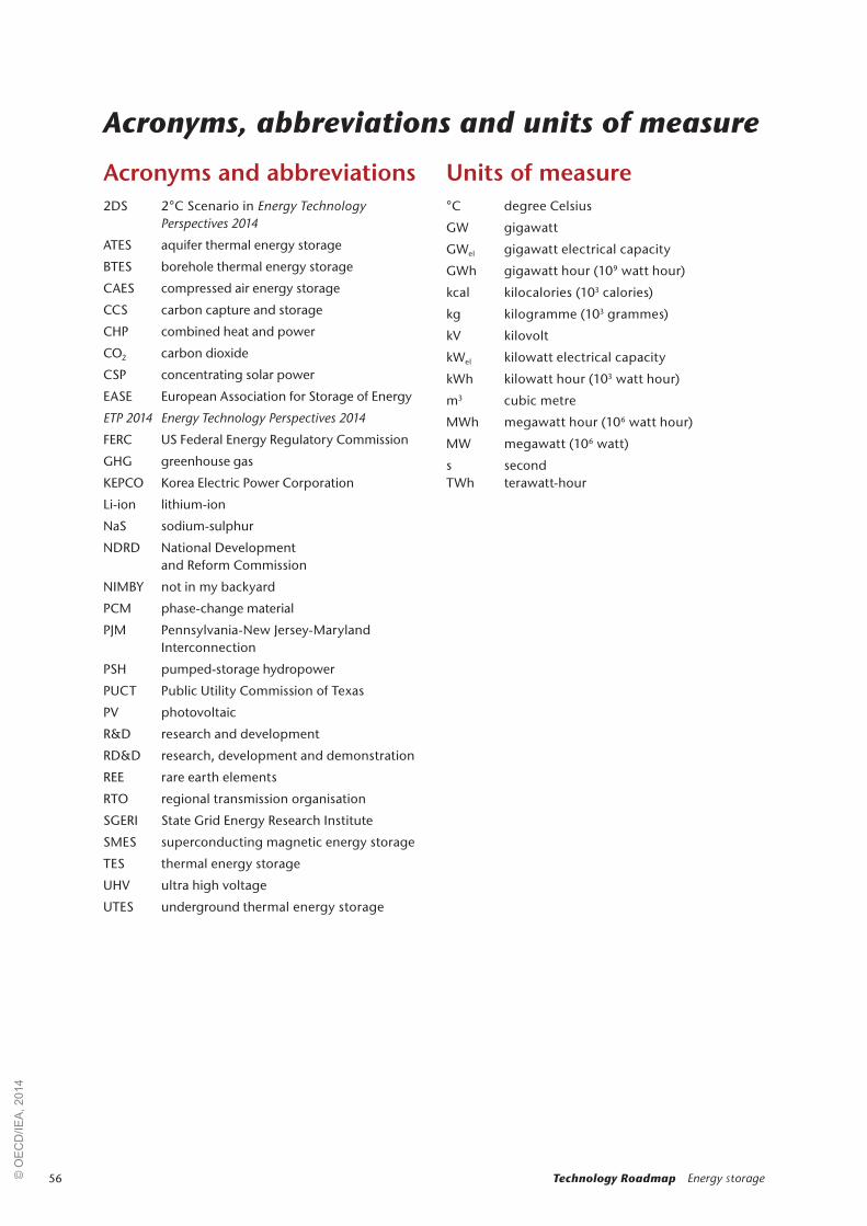
56 Technology Roadmap Energy storage
Acronyms and abbreviations2DS 2°C Scenario in Energy Technology
Perspectives 2014
ATES aquifer thermal energy storage
BTES borehole thermal energy storage
CAES compressed air energy storage
CCS carbon capture and storage
CHP combined heat and power
CO2 carbon dioxide
CSP concentrating solar power
EASE European Association for Storage of Energy
ETP 2014 Energy Technology Perspectives 2014
FERC US Federal Energy Regulatory Commission
GHG greenhouse gas
KEPCO Korea Electric Power Corporation
Li-ion lithium-ion
NaS sodium-sulphur
NDRD National Development and Reform Commission
NIMBY not in my backyard
PCM phase-change material
PJM Pennsylvania-New Jersey-Maryland Interconnection
PSH pumped-storage hydropower
PUCT Public Utility Commission of Texas
PV photovoltaic
R&D research and development
RD&D research, development and demonstration
REE rare earth elements
RTO regional transmission organisation
SGERI State Grid Energy Research Institute
SMES superconducting magnetic energy storage
TES thermal energy storage
UHV ultra high voltage
UTES underground thermal energy storage
Units of measure°C degree Celsius
GW gigawatt
GWel gigawatt electrical capacity
GWh gigawatt hour (109 watt hour)
kcal kilocalories (103 calories)
kg kilogramme (103 grammes)
kV kilovolt
kWel kilowatt electrical capacity
kWh kilowatt hour (103 watt hour)
m3 cubic metre
MWh megawatt hour (106 watt hour)
MW megawatt (106 watt)
s secondTWh terawatt-hour
Acronyms, abbreviations and units of measure
© O
EC
D/IE
A, 2
014

57
Battke, B., T.S. Schmidt, D. Grosspietsch and V.H. Hoffmann (2013), “A review and probabilistic model of lifecycle costs of stationary batteries in multiple applications”, Renewable and Sustainable Energy Reviews Vol. 25, pp. 240-250.
Beier, P. and P. Bretschneider (2013), “Modellbasierte, regional aufgelöste Analyse des Bedarfs an netzgekoppelten elektrischen Energiespeichern zum Ausgleich fluktuierender Energien“, final report, Bedarfsanalyse Energiespeicher, Frauenhofer Institute, Munich, Germany, www.iosb.fraunhofer.de/servlet/is/37913/04_IOSB_Jahresbericht-2012-2013_Standorte2.pdf.
Black & Veatch (2012), “Cost and performance data for power generation technologies”, Cost Report, February, Black & Veatch, Overland Park, Kansas, United Sates.
BMU (Federal Ministry for the Environement, Nature Conservation and Nuclear Safety) (2012), “Langfristszenarien und trategien fur den Ausbau der erneuerbaren Energien in Deutschland bei Berucksichtigung der Entwicklung in Europa und global”, BMU, Berlin, Germany.
BMWI (Federal Ministry for Economic Affairs and Energy) (2013), “Gesamtausgabe der Energiedaten - Datensammlung des BMWi”, Sheet 22, (database) August 20 update, Berlin, Germany, www.bmwi.de/BMWi/Redaktion/Binaer/energie-daten-gesamt,property=blob,bereich=bmwi2012, sprache=de,rwb=true.xls.
BNEF (Bloomberg New Energy Finance) (2013), “Views on the Role of Energy Storage” presented at the IEA (International Energy Agency) Energy Storage Technology Roadmap Stakeholder Engagement Workshop, Paris, France, 13 February.
Decourt, B. and R. Debarre (2013), “Electricity storage”, Factbook, Schlumberger Business Consulting Energy Institute, Paris, France.
Denholm, P. (2013), personal communication, 25 September.
Droste-Franke, B. (2013), “Future storage and balancing demand: ranges, significance and potential improvements of estimations”, presented at the 8th International Renewable Energy Storage Conference and Exhibition (IRES 2013), Berlin, 18 November.
EASE (European Association for the Storage of Energy) and EERA (European Energy Research Alliance) (2013), “Joint EASE/EERA recommendations for a European Energy Storage Technology Development Roadmap towards 2030”, EASE/EERA, Brussels, Belgium.
EC (European Commission) (2013), “Strategic research and innovation agenda for renewable heating & cooling”, European Technology Platform on Renewable Heating and Cooling, Publications Office of the European Union, Luxembourg, Luxembourg.
Ecofys and Bonneville Power Administration (2012), “TI 220 project evaluation report ”, September, Ecofys and Bonneville Power Administration, Corvallis and Portland. OR, United States.
EIA (Energy Information Administration) (2012), “Electricity storage: Location, location, location…..and cost”, Today in Energy, Washington, DC, United States, www.eia.gov/todayinenergy/detail.cfm?id=6910.
EPRI (Electric Power Research Institute) (2010), “Electrical Energy Storage Technology Options”, Report, EPRI, Palo Alto, CA, United States.
ETT (Electricity Transmission Texas) (2013), “Electric transmission Texas brings largest utility-scale battery in the United States to one of oldest cities in Texas”, PR Newswire, 8 April, New York.
EIA (Energy Information Administration) (2013), Annual Energy Outlook, Washington, DC
Enerdata (2011), Odyssee, the Europe Energy Efficiency Project, (database), Grenoble, France, http://enerdata.net/enerdatauk/solutions/data-management/odyssee.php.
ERCOT (Electric Reliability Council of Texas) (2008), ERCOT Board of Directors Meeting, 15 July, Taylor, TX, United States.
ESA (Electricity Storage Association) (2011), “Energy storage benefits: benefits stacking”, ESA, Washington, DC, United States, www.electricitystorage.org/technology/energy_storage_benefits/benefits_stacking.
Eurelectric (2009), “Statistics and prospects for the European electricity sector (1980-2000, 2004, 2005, 2006, 2010-2030)”, EURPROG 2008, Eurelectric, Brussels, Belgium.
References
References© O
EC
D/IE
A, 2
014

58 Technology Roadmap Energy storage
EU (European Union) (2012), “Energy efficiency, amending Directives 2009/125/EC and 2010/30/EU and repealing Directives 2004/8/EC and 2006/32/EC”, Directives, Office Journal of the EU, Brussels, Belgium.
EVI (Electric Vehicles Initiative) and IEA (International Energy Agency) (2013), Global EV Outlook, Paris, France.
Eyer, J. and G. Corey (2010), Energy Storage for the Electricity Grid: Benefits and Market Potential Assessment Guide, Sandia National Laboratory, Albuquerque, NM, United States.
Gimeno-Gutiérrez, M. and R. Lacal-Arántegui (2013), “Assessment of the European potential for pumped hydropower energy storage”, European Commission Joint Research Centre (JRC), Scientific and Policy Reports, Brussels, Belgium,http://ec.europa.eu/dgs/jrc/downloads/jrc_20130503_assessment_european_phs_potential.pdf.
Hauer, A., J. Quinnell and E. Lävemann (2013), Energy Storage Technologies - Characteristics, Comparison, and Synergies, Wiley-VCH Verlag GmbH & Co., Weinheim, Germany.
Hercberg, S. (2013), Personal communication.
IEA (International Energy Agency) (2014a), Energy Technology Perspectives, forthcoming, OECD/IEA, Paris, France.
IEA (2014b), The Power of Transformation: Wind, Sun and the Economics of Flexible Power Systems, OECD/IEA, Paris, France.
IEA (2012), Technology Roadmap: Hydropower, OECD/IEA, Paris, France.
IEA (2011), Technology Roadmap: Energy Efficient Buildings: Heating and Cooling Equipment, OECD/IEA, Paris, France.
IEA (2010), Technology Roadmap: Concentrating Solar Power, OECD/IEA, Paris, France.
IEA and Energy Research Institute (2011), Technology Roadmap: China Wind Energy Development Roadmap 2050, OECD/IEA, Paris, France.
IEA Energy Conservation through Energy Storage (ECES) (2011), Sustainable Cooling with Thermal Energy Storage, final report, Annex 20, November, www.iea-eces.org/files/annex20_finalreport_combined_nov4th_2011.pdf.
IEA-ETSAP (Energy Technology Systems Analysis Programme) and IRENA (2013), “Thermal Energy Storage”, Technology Brief E17, Bonn, Germany.
IEA-ETSAP and IRENA (International Renewable Energy Agency) (2012), “Electricity Storage”, Technology Policy Brief E18, Bonn, Germany.
Konidena, R. (2013), “Working Group 7 – 2012 Final Report on Energy Storage” presented at the IEA Energy Storage Technology Roadmap Stakeholder Engagement Workshop, Paris, France, 14 February, www.iea.org/media/freepublications/technologyroadmaps/6GO15WG7PresentationIEAworkshop.pdf.
NETL (National Energy Technology Laboratory) (2010), “Life cycle analysis: supercritical pulverized coal (SCPC) power plant", NETL, September, Pittsburgh, United States.
NETL (2009), “Estimating freshwater needs to meet future thermoelectric generation requirements”, NETL, September, Pittsburgh, United States.
NREL (National Renewable Energy Laboratories) (2013), Renewable Electricity Futures Study (RE Futures) Golden, CO, United States, www.nrel.gov/analysis/re_futures/.
O’Donnell, A. and K-A. Adamson (2012), Thermal Storage for HVAC in Commercial buildings, District Cooling and Heating, Utility and Grid Support Applications, and High-Temperature Storage at CSP Facilities, Pike Research, New York, United States.
Paksoy, H. (2013), “Thermal energy storage today” presented at the IEA Energy Storage Technology Roadmap Stakeholder Engagement Workshop, Paris, France, 14 February.
PJM Interconnection (2010), “Limited energy resources in capacity markets: problem statement”, paper prepared for August 5 meeting, Audubon, PA, United States, www.pjm.com/~/media/committees-groups/committees/mrc/20100805/20100805-item-10b-limited-energy-resources.ashx.
Rastler, D. (2011), Midwest Independent Transmission System Operator (MISO) Energy Storage Study Phase 1 Interim Report, EPRI, Palo Alto, United States, November, www.uwig.org/miso_energy_storage_study_phase_1_report.pdf.
Reske, H.J. (2010), “Texas pioneers energy storage in giant battery”, National Geographic, 25 March, Washington, DC, United States.
© O
EC
D/IE
A, 2
014

59
S&C Electric (2013), “The Role of Energy Storage in Smart Microgrids”, White paper, July, S&C Electric, Chicago, www.sandc.com/edocs_pdfs/edoc_076176.pdf.
Sandia National Laboratories (2010), Energy Storage for the Electricity Grid: Benefits and Market Potential Assessment Guide, A Study for the DOE Energy Storage Systems, Albuquerque, NM and Livermore, CA.
Sandia National Laboratories (2011), “Power Tower Technology Roadmap and Cost Reduction Plan”, Albuquerque, NM and Livermore, CA, United States, http://prod.sandia.gov/techlib/access-control.cgi/2011/112419.pdf#page19.
State Grid Energy Research Institute (SGERI) and Energy Research Institute (ERI) (2014), 2050 High Renewable Energy Scenarios for China, forthcoming, Beijing, China.
THEMA (2013), “Loop Flows – Final Advice”, Thema Report, Thema Consulting Group, Oslo, http://ec.europa.eu/energy/gas_electricity/studies/doc/electricity/201310_loop-flows_study.pdf.
US DOE (United States Department of Energy) (2013), DOE Global Energy Storage (database), www.energystorageexchange.org, (accessed in 2013).
US DOE (2012), Critical Materials Strategy, report, US DOE, Washington, DC, United States, http://energy.gov/sites/prod/files/DOE_CMS2011_FINAL_Full.pdf.
US EPA (Environmental Protection Agency) (2012), “Batteries: Just the Facts”, November, Washington, DC, United States, www.epa.gov/osw/conserve/materials/battery.htm.
Ying, J. (2011), “The future of energy storage technologies and policy”, Bloomberg New Energy Finance (database), (accessed on 12 April 2013).
Zucker, A., T. Hinchliffe, and A. Spisto (2013), “Assessing Storage Value in Electricity Markets”, Joint Research Centre (JRC) Scientific and Policy Reports, Petten, The Netherlands.
References© O
EC
D/IE
A, 2
014

This document and any map included herein are without prejudice to the status of or sovereignty over any territory, to the delimitation of international frontiers
and boundaries and to the name of any territory, city or area.
IEA Publications, 9 rue de la Fédération, 75739 PARIS CEDEX 15TYPESETTED AND PRINTED IN FRANCE BY IEA, MARCH 2014
Front cover photo (large): Thermal storage tanks at Naval Submarine Base Kinds Bay: waste treatment center, by Quentin Bowen, © Naval Facilities Engineering Command (NAVFAC), used under a Creative Commons Attribution-
NoDerivs 2.0 Generic License: http://creativecommons.org/licenses/by-nd/2.0/legalcodeFront cover photo (small): © ZenSchui
Back cover photo (large): San Luis Reservoir, pumped storage hydropower facility, © Jitze, used under a Creative Commons Attribution-NoDerivs 2.0 Generic License: http://creativecommons.org/licenses/by-nd/2.0/legalcode
Back cover photo (small): Portland General Electric’s Salem Smart Power Center with large scale battery storage, © Portland General Electric, used under a Creative Commons Attribution-NoDerivs 2.0 Generic License: http://creativecommons.org/licenses/by-nd/2.0/legalcode
© O
EC
D/IE
A, 2
014

www.iea.org/books
PDF versions at 20% discount
nlinebookshop
Tel: +33 (0)1 40 57 66 90
E-mail: [email protected]
International Energy Agency9 rue de la Fédération
75739 Paris Cedex 15, France
Bookshop_2014_Q_A4_Final.indd 1 31/01/2014 18:16:29
Secure Sustainable Together

2020
2025
2030
2014
2015
International Energy Agency – IEA9 rue de la Fédération, 75015 Paris, FranceTel: +33 (0)1 40 57 65 00/01, Fax: +33 (0)1 40 57 65 59Email: [email protected], Web: www.iea.org
Tech
nol
ogy
Roa
dm
ap
Ener
gy S
tora
ge