technology of the oil and gas drill pipe connector
TRANSCRIPT
A CTA TECHNICA CORVINIENSIS – Bulletin of Engineering Tome XI [2018] | Fascicule 4 [October – December]
47 | F a s c i c u l e 4
1.Vitalii PANCHUK, 2.Oleh ONYSKO, 3.Iuliia MEDVID
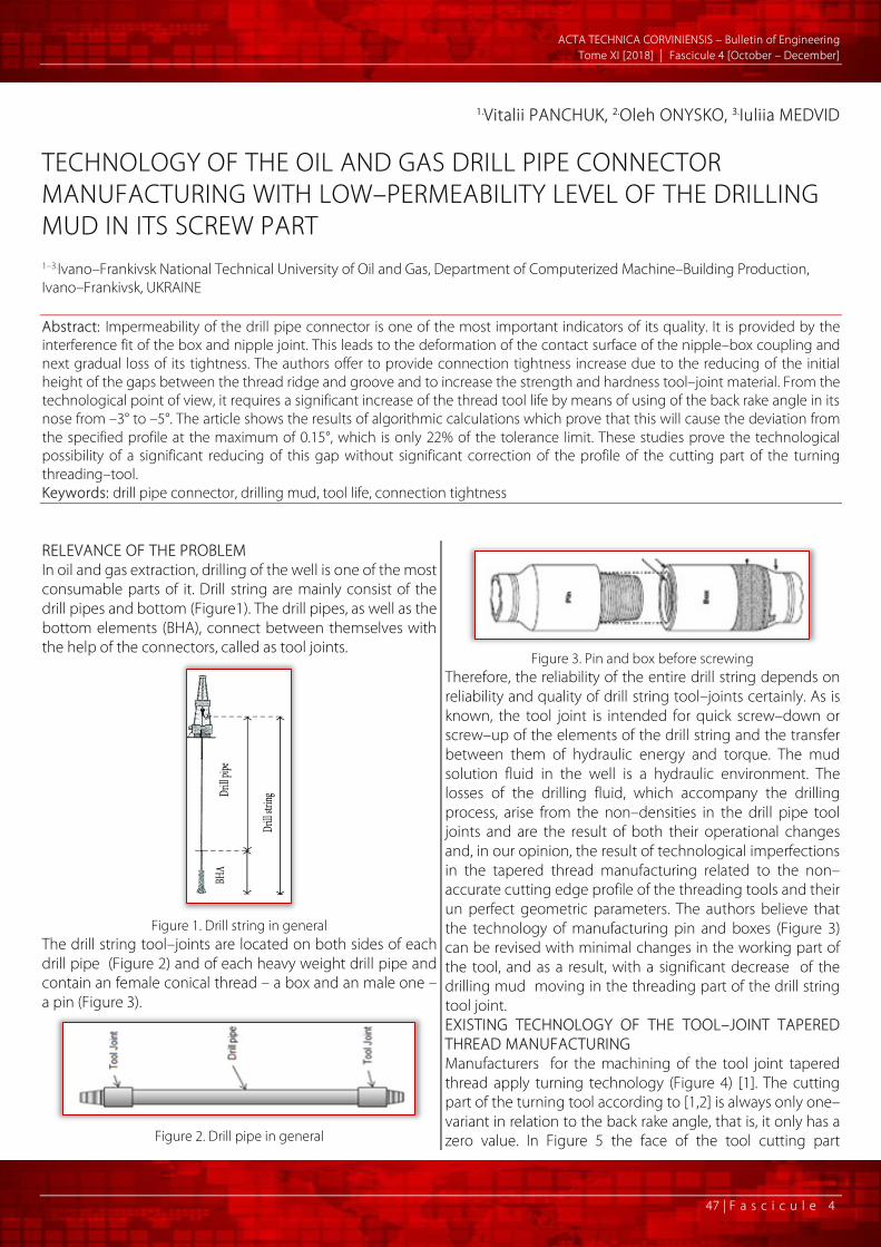
TECHNOLOGY OF THE OIL AND GAS DRILL PIPE CONNECTOR MANUFACTURING WITH LOW–PERMEABILITY LEVEL OF THE DRILLING MUD IN ITS SCREW PART 1–3.Ivano–Frankivsk National Technical University of Oil and Gas, Department of Computerized Machine–Building Production, Ivano–Frankivsk, UKRAINE Abstract: Impermeability of the drill pipe connector is one of the most important indicators of its quality. It is provided by the interference fit of the box and nipple joint. This leads to the deformation of the contact surface of the nipple–box coupling and next gradual loss of its tightness. The authors offer to provide connection tightness increase due to the reducing of the initial height of the gaps between the thread ridge and groove and to increase the strength and hardness tool–joint material. From the technological point of view, it requires a significant increase of the thread tool life by means of using of the back rake angle in its nose from –3° to –5°. The article shows the results of algorithmic calculations which prove that this will cause the deviation from the specified profile at the maximum of 0.15°, which is only 22% of the tolerance limit. These studies prove the technological possibility of a significant reducing of this gap without significant correction of the profile of the cutting part of the turning threading–tool. Keywords: drill pipe connector, drilling mud, tool life, connection tightness RELEVANCE OF THE PROBLEM In oil and gas extraction, drilling of the well is one of the most consumable parts of it. Drill string are mainly consist of the drill pipes and bottom (Figure1). The drill pipes, as well as the bottom elements (BHA), connect between themselves with the help of the connectors, called as tool joints.
Figure 1. Drill string in general
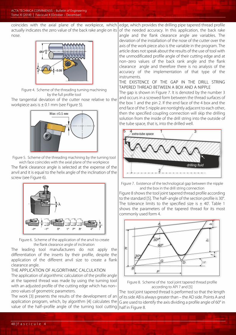
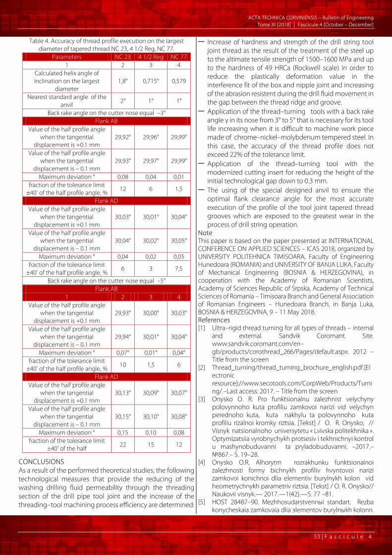
The drill string tool–joints are located on both sides of each drill pipe (Figure 2) and of each heavy weight drill pipe and contain an female conical thread – a box and an male one – a pin (Figure 3).
Figure 2. Drill pipe in general
Figure 3. Pin and box before screwing
Therefore, the reliability of the entire drill string depends on reliability and quality of drill string tool–joints certainly. As is known, the tool joint is intended for quick screw–down or screw–up of the elements of the drill string and the transfer between them of hydraulic energy and torque. The mud solution fluid in the well is a hydraulic environment. The losses of the drilling fluid, which accompany the drilling process, arise from the non–densities in the drill pipe tool joints and are the result of both their operational changes and, in our opinion, the result of technological imperfections in the tapered thread manufacturing related to the non–accurate cutting edge profile of the threading tools and their un perfect geometric parameters. The authors believe that the technology of manufacturing pin and boxes (Figure 3) can be revised with minimal changes in the working part of the tool, and as a result, with a significant decrease of the drilling mud moving in the threading part of the drill string tool joint. EXISTING TECHNOLOGY OF THE TOOL–JOINT TAPERED THREAD MANUFACTURING Manufacturers for the machining of the tool joint tapered thread apply turning technology (Figure 4) [1]. The cutting part of the turning tool according to [1,2] is always only one–variant in relation to the back rake angle, that is, it only has a zero value. In Figure 5 the face of the tool cutting part
A CTA TECHNICA CORVINIENSIS – Bulletin of Engineering Tome XI [2018] | Fascicule 4 [October – December]
48 | F a s c i c u l e 4
coincides with the axial plane of the workpiece, which actually indicates the zero value of the back rake angle on its nose.
Figure 4. Scheme of the threading turning machining
by the full profile tool The tangential deviation of the cutter nose relative to the workpiece axis is ± 0.1 mm (see Figure 5).
Figure 5. Scheme of the threading machining by the turning tool
wich face coincides with the axial plane of the workpiece The flank clearance angle is selected at the expense of the anvil and it is equal to the helix angle of the inclination of the screw (see Figure 6).
Figure 6. Scheme of the application of the anvil to create
the flank clearance angle of inclination The leading tool manufacturers do not apply the differentiation of the inserts by their profile, despite the application of the different anvil size to create a flank clearance angle. THE APPLICATION OF ALGORITHMIC CALCULATION The application of algorithmic calculation of the profile angle at the tapered thread was made by using the turning tool with an adjusted profile of the cutting edge which has non–zero values of geometric parameters. The work [3] presents the results of the development of an application program, which, by algorithm [4] calculates the value of the half–profile angle of the turning tool cutting
edge, which provides the drilling pipe tapered thread profile of the needed accuracy. In this application, the back rake angle and the flank clearance angle are variables. The deviation of the installation of the nose of the cutter over the axis of the work piece also is the variable in the program. The article does not speak about the results of the use of tool with the unmodificated profile angle of their cutting edge and at non–zero values of the back rank angle and the flank clearance angle and therefore there is no analysis of the accuracy of the implementation of that type of the instruments. THE EXISTENCE ОF THE GAP IN THE DRILL STRING TAPERED THREAD BETWEEN A BOX AND A NIPPLE The gap is shown in Figure 7. It is denoted by the number 3 and occurs in a screwed form between the thread surfaces of the box 1 and the pin 2. If the end face of the 4 box and the end face of the 5 nipple are nontightly adjacent to each other, then the specified coupling connection will skip the drilling solution from the inside of the drill string into the outside of the tube space, that is, into the drilled well.
Figure 7. Existence of the technological gap between the nipple
and the box in the drill string connection Figure 8 shows the tool joint tapered thread profile according to the standard [5]. The half–angle of the section profile is 30°. The tolerance limits to the specified size is ± 40'. Table 1 shows the parameters of the tapered thread for its most commonly used form 4.
Figure 8. Scheme of the tool joint tapered thread profile
according to API 7 and [5] The tool joint tapered thread is performed so that the length of its side AB is always greater than – the AD side. Points A and G are used to identify the axis dividing a profile angle of 60° in half in Figure 8.

A CTA TECHNICA CORVINIENSIS – Bulletin of Engineering Tome XI [2018] | Fascicule 4 [October – December]
49 | F a s c i c u l e 4
Table 1. Parameters of the tool joint tapered thread according to [5] for form IV
Name of parameter Value Pitch 6,35 mm
Thread Height Н 5,487 mm h1 work height 3,095 mm φ taper angle 4°45’48’’
Crest truncation, b* 1,427 mm root truncation, f 0,965 mm
Thread height truncated h* 2,633 mm Crest flat width а 1,651 mm
Root flat corner radius r 0,965 mm
Figure 9 illustrates the gap. On the left side the dimensions are indicated, and on the right corner for clarity the gap is painted in black. The radius of rounding r is actually intended for the design of the tool, and is not a mandatory dimension of the thread root. According to Figure 8 and Table 1, the height of the gap h1 – h is for Form IV – 0.462 mm.
Figure 9. Illustration of the technological gap of the drill string
tapered thread TECHNOLOGICAL NECESSITY OF THE GAP EXISTENCE IN THE THREAD SECTION OF THE DRILL STRING CONNECTION The value of h1 as an optional element does not affect the screw quality and the strength of the thread connection, but its reducing leads to a decrease in the height of the gap. At the same time, it is known that in the existing turning machining of the thread, the cutter (Figure 4) is used in many passes, for example, in a radial cutting (Figure 10) [1,2] to reach the full depth ap (see Figure 4). In this case, the cutting edge of the tool, which forms the thread root is worn mostly but the wear of that part of the cutting edge forming the crest is almost zero. This is obvious, since the thread crest is formed only during one or two the last passes by cutter. Thus, the existence of a gap with the value of h1 – h is grounded only by the manufacturing technology of the thread, since the value of h1 during the machining by cutter from pass to pass and from the product to the next product decreases and even theoretically h1 can reach the value of h. As a result, the value of h1 – h will be zero and further decrease will result in the inability to screw the tool joint due to the interference of the body of the box in the body of the pin. That is why it is necessary to consider this gap is technological, since it enables to use tool capable to cut during a certain period of its operation. This time in the machining process is called as tool life.
Figure 10. Scheme of multi–pass turning machining of the thread
with radial cutting HYDRAULIC LOSSES IN THE DRILL STRING CONNECTIONS Hydraulic losses that occur during the operation are described in [6]. Figures 11, 12 show graphs of the functional dependence of energy expenditure (J) on pressure (MPa) that develops in a drill string when the drilling mud is poured through it.
Figure 11. Dependence of losses of hydraulic energy in a
connection with a diameter of 101.6 mm, depending on the pressure of the drill pump at different values of the wear of the
tapered thread cut NC 46: 1. Δh = 0.1 mm, 2. Δh = 0.075 mm, 3 Δh = 0.05 mm, 4. Δh = 0.01 mm
Figure 12. Dependence of losses of hydraulic energy in a
connection with a diameter of 127 mm, depending on the pressure of the drill pump at different values of the wear of the
tapered thread cut NC 50: 1. Δh = 0.1 mm, 2. Δh = 0.075 mm, 3 Δh = 0.05 mm, 4. Δh = 0.01 mm

A CTA TECHNICA CORVINIENSIS – Bulletin of Engineering Tome XI [2018] | Fascicule 4 [October – December]
50 | F a s c i c u l e 4
The rate of the energy losses as seen from the graphs increases with an increase in thread wear Δh. Since according to [7] the thread groove during the operation almost is not worn out, that is, the value of the height of the profile h1 remains almost unchanged, but the mainly thread ridge and its flanks are worn that is, the value of thread height truncated h decreases. This decrease is actually the value Δh in Figures 11, 12. The works [8,9] represent the virtual exploration of the drill solution motion through the screw channels formed by the gap between the pin and the box of the drill string. tool joint. The authors [9] argue that with decreasing the width of the channel from the standard value a = 1.651 mm (see Table 1) to a = 1 mm, which corresponds to the decrease of the gap height in up about 0.3 mm, that is, from 0.46 mm to 0 ,15 mm, the speed of the washing fluid motion can be reduced by 20–30 times. Such a very significant decline in the opinion of the authors [9] should significantly reduce the hydraulic losses and abrasive wearing of the thread surface. THE CHARACTER OF THE CHANGE OF PROFILE OF THE TOOL JOINT TAPERED THREAD DUE TO ITS WEAR DURING OPERATION According to [7], the drill string tool joint thread root is subjected to the smallest wear in the process of operation is subjected and the crest and flanks of this thread are worn out quite intensively. Figure 13 depicts a scheme of the tapered thread according to standard [5] and additionally dotted cyan line describes the thread profile worn out during operation.
Figure 13. A diagram shows the nature of the drill pipe tapered thread wear. The numbers are indicated by: 1 – the largest flank according to the standard [5], 2 – crest, 3 –profile worn after the
operation, 4 – the root The value of Δh, as shown in Figure 13, indicates the value of the profile wearout of h (as in Figures 11, 12). There is unequal thread profile wear on the different ridges. Figure 14 illustrates the fact that ridges that are closer to the pin and box face ends are worn out bigger. In fact, they are thread ridges and grooves that correspond to their largest diameters. From the graph in Figure 14, we see that for the box, the highest degree of wear out corresponds to the turn number 1, and for the pin — number 15.
Thus, the problem of the tapered thread manufacture for the drill string is the presence of the gaps between a pin and a box to ensure the necessary technological tool life which in turn leads to significant costs of hydraulic energy and the of the abrasive wearout increment of the thread during operation. The purpose of the paper is to develop technological aspects that will ensure the manufacture of drill string tool joint with the low level of the washing fluid permeability through their threading part.
Figure 14. Degree of the wear out S of the every thread ridges
on the pin P and on the box B of the tool joint NC46 after testing on the drilling stand by the use of the multy times screwing
operation STATEMENT OF THE PROBLEM The task is to develop a technology to manufacture of drill string tupered thread with a reduced initial gap between groove and ridge of the box and pin, the lower intensity of wearout of the ridge and flanks by applying heat treating to increase its strength and hardness in providing the required tool life of the threading turning cutter by applying a nonzero value of its back rake angle and an optimal selection of the flank clearance angle. REDUCING THE INITIAL VALUE OF TECHNOLOGICAL GAP To reduce the initial value of the height of the gap, which is determined by the (h1 – h) formula previously adopted, it is more expedient to increase the value of h rather than reduce the value of h1. This is due to the fact that the thread root is formed by that part of the cutting edge threading tool, which wears out the most intensively, therefore it is inappropriate to reduce it. But it is quite reasonable to increase the value of h. That is, it is worth making this increase on the appropriate section of the cutting edge of the tool.
Figure 15. Photo of the cutting edge of the carbide insert of the cutter for drill string tapered thread machining for the form IV
(executed at 20–fold increase)

A CTA TECHNICA CORVINIENSIS – Bulletin of Engineering Tome XI [2018] | Fascicule 4 [October – December]
51 | F a s c i c u l e 4
Figure 15 shows a twenty–fold increase in the photo of the cutting edge tool for turning the tapered thread for drill string tool joint according to the form IV. Figure 16 according to the photo from Figure 15 shows a diagram illustrating the initial reducing of the gap h1 – h by replacing value h with the value h *> h. This can be done by correction of the shape of the cutting edge (red curve). In this case you can get a gap eg 0.3 mm less than the custom value. Recommendations of standard [5] indicate that it is supposed not to increase the value of h, but only to reduce to 0.18 mm for h / 2 size, but this tolerance limit is optional and serves in our opinion as the guarantee of required tool life .
Figure 16. The same photo as in Figure 15 but it is only with the
modified section of the cutting edge, which forms the crest of the tapered thread
Figure 17 illustrates the scheme for obtaining a reduced technological gap h1 – h *, which can be executed using a tool with modified cutting edge, as shown in Figure 16.
Figure 17. A diagram illustrating the reducing of the initial gap and increasing the theoretical limit of wear out by increasing the value
of h to h= h *. The digits are indicated by: 1 – the flank of the profile according to the standard, 2 – the crest according to the
standard, 3 – the profile of the thread after prolonged operation, 4 – the crest, which is executed by the corrected cutting edge, 5 –
cutting edge of the cutter after prolonged operation The red dotted line in Figure 17 indicates the most characteristic worn out cutting edge of the tool at the time of the completion of its technological tool life T. It is obvious that the value of h* cannot be provided with such shape of the cutting edge, since it has gone beyond the boundary of a figure placed between the dimensions h1 and h*. In this case, it is necessary to ensure the technological tool life by adjusting its geometric parameters: in the first place of back rank angle, as well as the flank clearance angle.
ENSURING THE TECHNOLOGICAL REQUIRED TOOL LIFE OF THE CUTTER Modern manufacturers of the threading turning tools offer cutters only with a zero value of the back rake because otherwise it is necessary to apply a rather complicated algorithm for calculating the cutting edge profile and thus increasing the number of the cutting inserts types. In this article, unlike [3], we offer the use of a carbide insert of a standard profile, but by changing the configuration of the substrate envilby using a non–zero back rake angle in the nose (see figure 18). So the face plane A–A thus passes at an angle γ to the axis of the workpiece, but does not pass through the axis as in the standard cutter, which is shown in figure 5.
Figure 18. Scheme of installation of the cutting insert, so that a
negative value of the back rake angle γ in its nose is ensured. The digits are indicated by: 1 – standard carbide insert, 2 – modified anvil, which implements the corresponding back rake angle, 3 –
cutter, 4 – body of the workpiece REDUCING THREAD WEAR OUT DUE TO INCREASING STRENGTH AND HARDNESS OF THE BODY A significant part of the steel grades for the drill string connectors manufacturing according to the strength characteristics can be classified into group of the difficult to machine materials. The brand of 40NiCrMo4KD — chromium–nickel–molybdenum steel, belongs to the group of high–quality steels, which is used for the manufacture of tool joint of drill string specified for complicated conditions of operation. Its mechanical characteristics are given in table 2.
Table 2. Mechanical characteristics of steel at different modes of heat treatment.
Tempering °C
Yield strength σ0,2 MPa
Ultimate strength σB
MPa
Hardness HRCa
200 1600 1750 53 300 1470 1600 49 400 1240 1370 44 500 1080 1170 38 600 860 960 28
According to [10], when the tempering of such steel is 600 for its successful cutting the back rake angle in the nose of cutter should be 0 °. If the ultimate tensile strength exceeds 1170 MPa (release of tempering is 500°C) then the back rake angle in the cutter nose for the carbide insert should be –5°. According to [11], when ultimate tensile strength is 1500 – 1600 MPa (if tempering is 300°C), the back rake angle for the carbide insert should be from –3° to –5°. Its depth of hardenability is over 15 mm. That is, the specific mechanical

A CTA TECHNICA CORVINIENSIS – Bulletin of Engineering Tome XI [2018] | Fascicule 4 [October – December]
52 | F a s c i c u l e 4
characteristics will relate to the whole body of the tool joint and the thread in particular. With such mechanical characteristics it is possible to predict: decrease in the intensity of abrasive abrasion of the thread
surface under the influence of a drill mud flow; increase of the tightness of the face ends connection of
the pin and the box due to the decrease in the value of plastic deformation under the influence of the Interference fit.
ENSURING OF THE MANUFACTURING PRECISION OF THE THREAD PROFILE ANGLE Table 3 summarizes the use results of the application for automated calculation of the size of the tapered thread half–profile angle made by cutter with the back rake angle at theits nose equal from –3° to –5°.
Table 3. Values of the deviation of the half profile angle of the tapered thread made by a cutter with a carbide insert of the usual profile with the application of the back rake angle of –3 ° and –5 °
Tool
join
t sta
ndar
d siz
e
Value of the half thread profile angle made by usual cutting edge of the turning
tool, °
Fraction of half thread profile
angle tolerance limit ±40', %
back rake equal –3°
back rake equal –5°
back rake
equal –3°
back rake
equal –5° AD AB AD AB
1 2 3 4 5 6 7 NC 23 30,03 29,89 30,14 29,90 – 16,4 20,9
2 3/8 Reg 30,03 29,89 30,13 29,91 –16,4 19,4 NC 26 30,03 29,91 30,13 29,92 –13,4 19,4
2 7/8 Reg 30,03 29,91 30,13 29,93 –13,4 19,4 NC 31 30,03 29,93 30,125 29,96 –10,4 18,6
3 1/2 Reg 30,03 29,93 30,12 29,96 –10,4 17,9 NC 35 30,03 29,94 30,12 29,97 –8,9 17,9
3 1/2 FN 30,025 29,94 30,11 29,98 –8,9 16,4 NC 38 30,03 29,95 30,12 29,98 –7,4 17,9 NC 40 30,03 29,95 30,12 29,98 –7,4 17,9
4 1/2 Reg 30,02 29,95 30,10 29,99 –7,4 14,9 NC 44 30,03 29,96 30,11° 29,99 –5,9 16,4
4 1/2 FH 30,02 29,96 30,10 29,99 –5,9 14,9 NC 46 30,03 29,96 30,11 29,99 –5,9 16,4 NC 50 30,03 29,97 30,105° 30,01 ±4,5 15,7
5 1/2 Reg 30,05 29,96 30,10 29,99 7,4 14,9 5 1/2 FH 30,02 29,98 30,10 30,02 ±2,9 14,9
NC 56 30,05 29,96 30,13 29,99 7,4 19,4 6 5/8 Reg 30,03 29,98 30,105 30,02 4,5 15,7
NC 61 30,05 29,97 30,13 30,00 7,4 19,4 6 5/8 FH 30,03 29,99 30,105 30,03 4,5 15,7
7 5/8 Reg 30,01 29,98 30,09 30,02 –2,9 13,4 NC 70 30,01 29,98 30,09 30,02 –2,9 13,4
8 5/8 Reg 30,00 29,98 30,08 30,03 2,9 11,9 NC 77 30,01 29,99 30,08 30,03 1,5 11,9
Column 1 lists drill string tool joints of all sizes in accordance to API 7 and [5]. Columns 2 and 3 shows data on the magnitudes of half profile angles obtained with a cutter with a standard cutting edge, but the underlay anvil provides the
value of the back rake c angle at the its nose of –3 °. Column 2 is filled in with data about the half profile angle at the side AD, and column 3 – at the side AB. Columns 4 and 5 shows data on the magnitudes of half profile angles obtained with a cutter with a standard cutting edge, but the underlay anvil provides the value of the back rake c angle at the its nose of –5 °. Column 4 is filled in with data about the half profile angle at the side AD, and column 5 – at the side AB. Columns 6, 7 indicate the percentage of the part of the tolerance limit of the half thread profile angle of which is ± 40 '. This fraction is calculated from the greater deviation from each pair and taking into account the sign. These tables indicate that the fraction of the half–profile angle tolerance limit does not exceed 21% when the value of the back rake angle is –5° and 16.5% when the back rake angle value is –3°. The flank clearance angle in these calculations is assumed to be equal to the helix angle of inclination in the smallest diameter of the tapered thread. Proceeding from this, the most theoretically possible its values are accepted in calculations shown in table 3. However, since it is generally acceptable for the manufacturer to product a limited number of standard sizes of the anvil (see Figure 6), then the algorithmic calculation [4] should be used to obtain the most optimal values of the flank clearance angle – that is, to pick up the anvil with the nearest integer angle of inclination. ACCURACY OF THE MANUFACTURING OF THE MOST LOADED TAPERED THREAD RIDGES PROFILE OF THE DRILL STRING TOOL JOINT Figure 14 proves that the greatest wear out is on the turn of the thread , which are located on larger conical diameter. This appoint a priority task to ensure the highest accuracy of the profile of the specified turns. Accordingly, the algorithm proposed in [4] should be used to establish deviations from the half–profile angle nominal, provided that the flank clearance angle is equal to the helix angle of inclination of the tapered thread in its largest diameter. In calculations are that tool joints: of the smallest size – NC 23, one of the avengers – 4 1/2 Reg and of the largest size NC 77. To the input parameters of the algorithm, the tangential displacement of the nose of the cutter ± 0,1 mm is added, ( as it is illustrated in Figure 5). These tables show the tendency to decrease the fraction from the tolerance limit of ± 40 ' from the nominal half– profile angle equal 30 ° when the tool joint size changes from the smallest to the largest. The largest fraction is 22%, the smallest 1.5%, taking into account the accuracy of the installation of the nose of the tool, the displacement of which is ± 0,1 mm. The indicated fractions demonstrate the probable feasibility to use the cutters with such parameters for their practice in the manufacture of tapered thread with a low level of permeability of the drilling solution in it.
A CTA TECHNICA CORVINIENSIS – Bulletin of Engineering Tome XI [2018] | Fascicule 4 [October – December]
53 | F a s c i c u l e 4
Table 4. Accuracy of thread profile execution on the largest diameter of tapered thread NC 23, 4 1/2 Reg, NC 77.
Parameters NC 23 4 1/2 Reg NC 77 1 2 3 4
Calculated helix angle of inclination on the largest
diameter 1,8° 0,715° 0,579
Nearest standard angle of the anvil 2° 1° 1°
Back rake angle on the cutter nose equal –3° Flank АВ
Value of the half profile angle when the tangential
displacement is +0.1 mm 29,92° 29,96° 29,99°
Value of the half profile angle when the tangential
displacement is – 0.1 mm 29,93° 29,97° 29,99°
Maximum deviation ° 0,08 0,04 0,01 fraction of the tolerance limit
±40' of the half profile angle, % 12 6 1,5
Flank АD Value of the half profile angle
when the tangential displacement is +0.1 mm
30,03° 30,01° 30,04°
Value of the half profile angle when the tangential
displacement is – 0.1 mm 30,04° 30,02° 30,05°
Maximum deviation ° 0,04 0,02 0,05 fraction of the tolerance limit
±40' of the half profile angle, % 6 3 7,5
Back rake angle on the cutter nose equal –5° Flank АВ
1 2 3 4 Value of the half profile angle
when the tangential displacement is +0.1 mm
29,93° 30,00° 30,03°
Value of the half profile angle when the tangential
displacement is – 0.1 mm 29,94° 30,01° 30,04°
Maximum deviation ° 0,07° 0,01° 0,04° fraction of the tolerance limit
±40' of the half profile angle, % 10 1,5 6
Flank АD Value of the half profile angle
when the tangential displacement is +0.1 mm
30,13° 30,09° 30,07°
Value of the half profile angle when the tangential
displacement is – 0.1 mm 30,15° 30,10° 30,08°
Maximum deviation ° 0,15 0,10 0,08 fraction of the tolerance limit
±40' of the half 22 15 12
CONCLUSIONS As a result of the performed theoretical studies, the following technological measures that provide the reducing of the washing drilling fluid permeability through the threading section of the drill pipe tool joint and the increase of the threading–tool machining process efficiency are determined:
— Increase of hardness and strength of the drill string tool joint thread as the result of the treatment of the steel up to the altimate tensile strength of 1500–1600 MPa and up to the hardness of 49 НRCa (Rockwell scale) in order to reduce the plastically deformation value in the interference fit of the box and nipple joint and increasing of the abrasion resistent during the drill fluid movement in the gap between the thread ridge and groove.
— Application of the thread–turning tools with a back rake angle γ in its nose from 3° to 5° that is necessary for its tool life increasing when it is difficult to machine work piece made of chrome–nickel–molybdenum tempered steel. In this case, the accuracy of the thread profile does not exceed 22% of the tolerance limit.
— Application of the thread–turning tool with the modernized cutting insert for reducing the height of the initial technological gap down to 0.3 mm.
— The using of the special designed anvil to ensure the optimal flank clearance angle for the most accurate execution of the profile of the tool joint tapered thread grooves which are exposed to the greatest wear in the process of drill string operation.
Note This paper is based on the paper presented at INTERNATIONAL CONFERENCE ON APPLIED SCIENCES – ICAS 2018, organized by UNIVERSITY POLITEHNICA TIMISOARA, Faculty of Engineering Hunedoara (ROMANIA) and UNIVERSITY OF BANJA LUKA, Faculty of Mechanical Engineering (BOSNIA & HERZEGOVINA), in cooperation with the Academy of Romanian Scientists, Academy of Sciences Republic of Srpska, Academy of Technical Sciences of Romania – Timisoara Branch and General Association of Romanian Engineers – Hunedoara Branch, in Banja Luka, BOSNIA & HERZEGOVINA, 9 – 11 May 2018. References [1] Ultra–rigid thread turning for all types of threads – internal
and external. Sandvik Coromant. Site. www.sandvik.coromant.com/en–gb/products/corothread_266/Pages/default.aspx. 2012 – Title from the screen
[2] Thread_turning/thread_turning_brochure_english.pdf.[Electronic resource]://www.secotools.com/CorpWeb/Products/Turning/.–Last access: 2017. – Title from the screen
[3] Onysko O. R. Pro funktsionalnu zalezhnist velychyny polovynnoho kuta profiliu zamkovoi narizi vid velychyn perednoho kuta, kuta nakhylu ta polovynnoho kuta profiliu rizalnoi kromky riztsia. [Tekst] / O. R. Onysko, // Visnyk natsionalnoho universytetu « Lvivska politekhnika ». Optymizatsiia vyrobnychykh protsesiv i tekhnichnyi kontrol u mashynobuduvanni ta pryladobuduvanni. –2017.– №867.– S. 19–28.
[4] Onysko O.R. Alhorytm rozrakhunku funktsionalnoi zalezhnosti formy bichnykh profiliv hvyntovoi narizi zamkovoi konichnoi dlia elementiv burylnykh kolon vid heometrychnykh parametriv riztsia. [Tekst] / O. R. Onysko// Naukovii visnyk.— 2017.—1(42).—S. 77 –81.
[5] HOST 28487–90. Mezhhosudarstvennыi standart. Rezba konycheskaia zamkovaia dlia эlementov burylnыkh kolonn.

A CTA TECHNICA CORVINIENSIS – Bulletin of Engineering Tome XI [2018] | Fascicule 4 [October – December]
54 | F a s c i c u l e 4
Profyl. Razmerы. Dopusky (s Yzmenenyem N 1 [Tekst]. Utverzhden y vnesen v deistvye postanovlenyem Hosudarstvennoho komyteta SSSR po standartam ot 05.06.80 № 2578. M.: «Standartynform», 2010. — 75 s.
[6] Chudyk I.I. Do vtrat hidravlichnoi enerhii pid chas promyvannia sverdlovyny. Rozvidka ta rozrobka naftovykh i hazovykh rodovyshch. – 2009.– №2(31).– S34–42.
[7] Semyn V.Y. Sovremennye metody proektirovaniya rezbovyh soedinenyj trub neftegazovogo sortamenta dlya stroytelstva skvazhyn [Tekst]: dys. … dokt. texn. nauk : 25.00.15, 05.02.13 / Semyn Vladimyr Yvanovych – Moskva, 2005. – 344 s. – Byblyogr.: s.232–344.
[8] Liubomyr Borushchak.Research of the impermeability of the tool–joint tapered thread size 2 7/8 reg/ Liubomyr Borushchak, Oleh Onysko, Vitalii Panchuk //Monografia “Problemy eksploatacji I zarządzania w górnitctwie” rząd Górnictwo–Kraków 2017 p.65–72.
[9] Liubomyr Borushchak. Influence of the technological gap value of the tool–joint tapered thread on the drilling mud flow rate in its screw coupling/ Lubomyr Borushchak, Stepan Borushchak , Oleh Onysko //Ukrainian Jornal of Mechanical Engineering and Materials Sciance.–2017.–Volume 3.–№2.P. 24–31.
[10] Fomin E. V. Povyshenye stojkosty i tochnosti rezbovyx rezczov na osnove modelirovanyya processa rezbonarezaniya [Tekst]: dys. … kand. texn. nauk : 05.03.01 : Fomyn Evgenyj Vladymyrovych – M., 2007. – 206 s. – Byblyogr.: s. 194–202.
[11] Ya. L. Gurevych Rezhymy rezaniya trudnoobrabatyvaemyx materyalov: Spravochnyk/Ya. L. Gurevy`ch, M. V. Goroxov, V. Y. Zaxarov y dr. 2–e y`zd., pererab. y dop.—M.: Mashynostroenye, 1986, 240 s, l.
ISSN: 2067–3809
copyright © University POLITEHNICA Timisoara, Faculty of Engineering Hunedoara,
5, Revolutiei, 331128, Hunedoara, ROMANIA http://acta.fih.upt.ro