technologie services its · isolation technologie services - sarl au capital de 7000 euros - siège...
TRANSCRIPT

Isolation Technologie Services - SARL au capital de 7000 Euros - Siège social : 3 route du Mont Cindre F-69450 Saint Cyr au Mont d’Or
Tél. +33(0) 952 36 35 31 - Fax +33(0) 957 36 35 31 - E-mail: [email protected] - Internet: www.its-acoustique.fr
Sound Impact Limitation - Design for Industrialized Solutions (SILDIS): a single Excel based software for a wide range of applications
Updated by Philippe Reynaud on July 2017 the 25th ([email protected])
Overview of features
▪ the prediction of performances of products and construction systems for noise control engineering often
requires an approach whose nature is computationally intensive, making its application difficult for most acoustics practitioners. The software SILDIS (Sound Impact Limitation Design for Industrialized Solutions) has been developed in order to make possible such a prediction without any computational effort from users, by the means of a single PC-tool appropriate for a wide range of industrial engineering purposes, with a reliability based on the agreement of the prediction results with existing computation schemes and with measurement results (hundreds of comparisons for various types of computations)
▪ regarding the multi-disciplinary scientific and technical background, suitable approaches of all times, able to be
included in the general layout of the program, have been selected and encapsulated in a easy-to-use Excel based software using drop-down menus and providing results in tabular and graphical form (French or English language) with comprehensive input/output data on a unique printable simulation report.
▪ as far as materials are concerned (such as porous media, series cloths, series perforated protections, and thin
plates: see below), specific libraries (data bases) with more than 20 references for each kind of acoustic layer
allow the design to be made with in-built engineering data (constants).
▪ almost all acoustics calculations are performed at single frequencies (20-20kHz) and displayed per 1/3 and/or 1/1 octave band: global values with respect to a chosen reference spectrum are computed whenever it makes sense. MODULE 1 prediction of acoustic and aerodynamic performance of silencers:
o either dissipative silencers (for those equipments the considered cross section can be either rectangular or round, with or without a central pod, with or without an intermediate annular splitter) for a lining including up to 4 porous media, up to 4 series cloths, up to 4 series perforated protections selected among a library including for each kind of layer more than 20 referenced materials.
o or resonant silencers with so called Pine Tree splitters (for those equipments the considered cross section can be rectangular) for a lining including up to 4 porous media, up to 4 series cloths, up to 4 series perforated protections selected among a library including for each kind of layer more than 20 referenced materials
For a rectangular silencer the results of the calculations are comparable with the standardized measurement: see NF EN ISO 7235 Acoustics - Laboratory measurement procedures for ducted silencers and air terminal units- Insertion loss, flow noise and total pressure loss. MODULE 1A prediction of acoustic and aerodynamic performance of silencers with discontinued splitters:
o dissipative silencers (considered cross section being rectangular) for a lining including 1 porous medium, 1 series cloth, 1 series perforated protection (material properties registered in database)
For a rectangular silencer the results of the calculations are comparable with the standardized measurement: see NF EN ISO 7235 Acoustics - Laboratory measurement procedures for ducted silencers and air terminal units- Insertion loss, flow noise and total pressure loss. MODULE 1B prediction of acoustic and aerodynamic performance of reactive silencers:
For those equipments the considered cross section can be round) for an elements combination including up to 1 uniform tube, up to 2 extended tubes The obtained results are not comparable with standardized measurement due to the lack of documents formalizing corresponding measurement procedures. MODULE 2 prediction of acoustic performance of plane partitions
o for an acoustic structure including up to 2 porous media, up to 2 series cloths, up to 2 series perforated
protections, up to 2 sets of identical series thin plates with up to 1 complementary rear set of identical
ITS acoustique
Report PhR17-013A
ITS acoustique
I s o l a t i o n Technologie Services

Report Date Page
PhR17-013A 25-07-2017 2/39
Isolation Technologie Services - SARL au capital de 7000 Euros - Siège social : 3 route du Mont Cindre F-69450 Saint Cyr au Mont d’Or Tél. +33(0) 952 36 35 31 - Fax +33(0) 957 36 35 31 - E-mail: [email protected] - Internet: www.its-acoustique.fr
series thin plates selected among a library including for each kind of layer more than 20 referenced materials (with an atmospheric back or with an impervious rigid back).
The results of the calculations are comparable with the standardized measurement: (in case of an atmospheric
back) see NF EN ISO 10140-2 Acoustics. Laboratory measurement of sound insulation of building elements. Measurement of airborne sound insulation and (in case of rigid impervious back) see NF EN ISO 354 Acoustics – Measurement of sound absorption in a reverberation room and also ISO 10534-1 Acoustics – Determination of sound absorption coefficient and impedance in impedance tubes – Part 1: Method using standing wave ratio. MODULE 3 prediction of acoustic performance of duct walls: o either with a rectangular cross section, or with a circular cross section (including folded spiral seam ducts) The obtained results are not comparable with standardized measurement due to the lack of documents formalizing corresponding measurement procedures. MODULE 4 prediction of acoustic performance of straight ducts o either with a rectangular cross section, or with a circular cross section (including folded spiral seam ducts)
The obtained results are not comparable with standardized measurement due to the lack of documents
formalizing corresponding measurement procedures. MODULE 5 prediction of break-out noise: either of straight ducts o with a rectangular cross section, or with a circular cross section - including folded spiral seam ducts or of
silencers The obtained results are not comparable with standardized measurement due to the lack of documents
formalizing corresponding measurement procedures. MODULE 5A prediction of break-out noise of ducts with variable cross section (with a rectangular cross section) The obtained results are not comparable with standardized measurement due to the lack of documents formalizing corresponding measurement procedures. MODULE 6 prediction of acoustic performances of bends (in ducts systems) o with a rectangular cross section, or with a circular cross section, or with mixed cross sections) The obtained results are not comparable with standardized measurement due to the lack of documents formalizing corresponding measurement procedures. MODULE 7 prediction of nozzle reflection o with a rectangular cross section or with a circular cross section The obtained results are not comparable with standardized measurement due to the lack of documents formalizing corresponding measurement procedures. MODULE 8 prediction of the sound impact of duct systems
o including components such as silencers (dissipative or resonant), straight ducts sections, bends with a rectangular cross section, or with a circular cross section, or with mixed cross sections (for some components)
MODULE 8A prediction of stacks directivity
Some of the obtained results are comparable with some input data envisaged in standardized calculation: cf. NF EN ISO 9613-2 Acoustics -- Attenuation of sound during propagation outdoors -- Part 2: General method of
calculation (1996) MODULE 8B prediction of atmospheric sound absorption Some of the obtained results are comparable with some input data envisaged in standardized calculation: cf. NF EN ISO 9613-2 Acoustics -- Attenuation of sound during propagation outdoors -- Part 2: General method of calculation (1996) MODULE 8C prediction of control valves aerodynamic noise

Report Date Page
PhR17-013A 25-07-2017 3/39
Isolation Technologie Services - SARL au capital de 7000 Euros - Siège social : 3 route du Mont Cindre F-69450 Saint Cyr au Mont d’Or Tél. +33(0) 952 36 35 31 - Fax +33(0) 957 36 35 31 - E-mail: [email protected] - Internet: www.its-acoustique.fr
MODULE 8D prediction of jet noise (including safety valves noise)
MODULE 8E prediction of piping systems discharge parameters
MODULE 9 modelling of sound decay in enclosed spaces The obtained results are comparable with standardized measurement: cf. NF EN ISO 3382-2 Acoustics - Measurement of room acoustics parameters- Part 2: reverberation time in ordinary rooms. MODULE 9A prediction of sound spatial decay in open-plan offices Some of the obtained results are comparable with standardized measurement NF EN ISO 3382-3 Acoustics -Measurement of room acoustics parameters- Part 3: Open plan offices.
Applications ▪ SILDIS is useful for consulting projects and products/construction systems development projects
involving sound reduction/airborne noise insulation by the means of passive acoustics solutions in various domains: protection of workers, protection of environment, energy sector, measurement rooms,
building
ITS acoustique

Report Date Page
PhR17-013A 25-07-2017 4/39
Isolation Technologie Services - SARL au capital de 7000 Euros - Siège social : 3 route du Mont Cindre F-69450 Saint Cyr au Mont d’Or Tél. +33(0) 952 36 35 31 - Fax +33(0) 957 36 35 31 - E-mail: [email protected] - Internet: www.its-acoustique.fr
Page intentionally left blank

Report Date Page
PhR17-013A 25-07-2017 5/39
Isolation Technologie Services - SARL au capital de 7000 Euros - Siège social : 3 route du Mont Cindre F-69450 Saint Cyr au Mont d’Or Tél. +33(0) 952 36 35 31 - Fax +33(0) 957 36 35 31 - E-mail: [email protected] - Internet: www.its-acoustique.fr
Scope of computation ▪ design of devices reducing the acoustic transmission in a duct, a pipe or an aperture, without preventing the
carriage of the fluid (dissipative: attenuating the wideband sounds with a relatively low pressure loss and converting partially the acoustic energy into heat by friction on tubes having a porous or fibrous structure or resonant: with Pine Tree splitters producing an acoustic attenuation from weakly damped resonances of elements containing or not containing absorbing materials - at the rear of the chambers or lateral -).
Applications
▪ creation of a sound transmission loss by the means of the construction of a silencer possibly included in
a (soundproofing) industrial building/ booth/wall/screen: protection of workers, protection of environment, energy sector, measurement rooms, building, notably:
✓ ventilation of enclosures and/or air input for thermodynamic processes for various noisy equipments
such as fans, aero condensers, engines, gas turbines… ✓ ventilation of test benches and/or air input for thermodynamic processes of test benches… ✓ noise reduction of stacks, exhaust of gas turbines…
Computation scheme (bloc diagram) for dissipative silencers: adapted for resonant silencers
Main/special features, main effects taken into account
▪ design possible for multilayered acoustic structures: most sophisticated acoustic structure available (for
the lining / for half a splitter) as shown on the figure below (air flow according x-direction, thickness of the lining / half a splitter according y-direction)
▪ ▪
▪ for an acoustic structure including a porous medium (i.e. polyester, rock wool, basalt wool, glass wool, foam …for which the engineering data can be referenced or air): behavior taken into account from to the microscopic scale level in relation with the properties such as flow resistivity [cf. fig. 1] and other parameters for a locally reacting absorber or a bulk reacting absorber with a possible inhomogeneity of properties such as flow resistivity (σx, σy on figures below) or other parameters, of 1 layer in directions perpendicular to and
parallel to its surface [cf. fig. 2]
item layer (*)
C, G, K, O porous medium (**)
D, H, L, P series cloth (**)
E, I, M, Q series perforated protection (**)
* selected among a library including for each kind of layer more than 20
referenced materials
**some cloths and some perforated protections can also be considered as
porous layers for the computation
Computation of silencers
ITS acoustique
ITS acoustique
ITS acoustique
ITS acoustique

Report Date Page
PhR17-013A 25-07-2017 6/39
Isolation Technologie Services - SARL au capital de 7000 Euros - Siège social : 3 route du Mont Cindre F-69450 Saint Cyr au Mont d’Or Tél. +33(0) 952 36 35 31 - Fax +33(0) 957 36 35 31 - E-mail: [email protected] - Internet: www.its-acoustique.fr
▪ effect of a laminated lining (for each layer: different properties such as flow resistivity [cf. fig. 3] or other different parameters): taken into account
▪ effect of a cloth (i.e. fabric, unwoven…for which the engineering data can be referenced): taken into account
[cf. fig. 4]
▪ for an acoustic structure including a perforated protection (i.e. perforated sheet with circular holes and square or hexagonal array, perforated sheet with square holes, infinite slots… for which the engineering data can be referenced): interaction of the protection with a porous medium at the front/at the rear taken into account [cf. fig. 5]
▪ by-pass correction taken into account [cf. fig. 6]
▪ reflection loss taken into account [cf. fig. 7]
▪ effect of temperature/of pressure taken into account [cf. fig. 8] [cf. fig. 9]
▪ effect of the velocity of air flow (other than self noise [cf. fig. 10], self noise [cf. fig. 11]) taken into account
▪ different possible geometries for the splitters/the lining: rectangular, semi circular or profiled aerodynamic type upstream/downstream (cross section for a dissipative silencer: rectangular, square or round - with or
without central pod, with or without up to 3 intermediate annular splitters -, cross section for a resonant silencer: rectangular)
Fig. 7 Fig. 8
Fig. 5 Fig. 6
Fig. 3 Fig. 4
Fig. 1 Fig. 2
propagation loss Da
0
5
10
15
20
25
30
35
40
1 10 100 1000 10000 100000f(Hz)
Da (
dB
/m)
12kNsm-4
72kNsm-4
mix
0
20
40
60
80
100
120
1 10 100 1000 10000 100000
Da*L
(d
B)
f(Hz)
longitudinal attenuation Da*L
σx1/σy1=∞ σx1/σy1=1 σx1/σy1=var.
propagation loss Da
0
5
10
15
20
25
30
35
40
45
1 10 100 1000 10000 100000f(Hz)
Da (
dB
/m)
8kNsm-4
12kNsm-4
16kNsm-4
24kNsm-4
48kNsm-4
72kNsm-4
propagation loss Da
0
10
20
30
40
50
60
70
1 10 100 1000 10000 100000
f(Hz)
Da (
dB
/m)
without with
propagation loss Da
0
5
10
15
20
25
30
35
1 10 100 1000 10000 100000f(Hz)
Da (
dB
/m)
without with
longitudinal attenuation Da*L
0
10
20
30
40
50
60
70
1 10 100 1000 10000 100000f(Hz)
Da*L
(d
B)
without with
insertion loss Di
0
5
10
15
20
25
30
35
1 10 100 1000 10000 100000f(Hz)
Di (d
B)
without with
propagation loss Da
0
20
40
60
80
100
120
1 10 100 1000 10000 100000f(Hz)
Da (
dB
/m)
20 °C 300 °C 600 °C

Report Date Page
PhR17-013A 25-07-2017 7/39
Isolation Technologie Services - SARL au capital de 7000 Euros - Siège social : 3 route du Mont Cindre F-69450 Saint Cyr au Mont d’Or Tél. +33(0) 952 36 35 31 - Fax +33(0) 957 36 35 31 - E-mail: [email protected] - Internet: www.its-acoustique.fr
Main results displayed for the acoustic structure used for the lining/half a splitter (with an impervious rigid back/a symmetry plane):
▪ complex surface impedance for normal incidence: Z per 1/3 and 1/1 octave frequency band
▪ absorption coefficient at normal incidence: α0 per 1/3 and 1/1 octave frequency band
▪ the results of the calculations are comparable with the standardized measurement: see ISO 10534-1
Acoustics – Determination of sound absorption coefficient and impedance in impedance tubes – Part 1: Method using standing wave ratio.
Main displayed results for the silencer (tables and graphs):
▪ total pressure loss (and non dimensional total pressure loss coefficient)
▪ insertion loss without flow: for 3 usual different conditions of propagation of sound inside the lining per 1/1
octave frequency band (as well as A-weighted overall value with respect to a reference spectrum)
▪ insertion loss with flow without flow noise Di’(detailing longitudinal attenuation Da.L, bypass correction Dk and reflection loss Dr) for 3 usual different conditions of propagation of sound inside the lining per 1/3 and 1/1 octave frequency band (as well as A-weighted overall value with respect to a reference spectrum)
▪ self noise (acoustic power of flow noise) per 1/1 octave frequency band (as well as A-weighted overall value)
Fig. 9 Fig. 10
Fig. 11
propagation loss Da
0
5
10
15
20
25
30
35
40
1 10 100 1000 10000 100000f(Hz)
Da (
dB
/m)
100kPa 200kPa 400kPa
longitudinal attenuation Da*L
0
10
20
30
40
50
60
70
1 10 100 1000 10000 100000f(Hz)
Da*L
(d
B)
v=0 ms-1 v=-10ms-1 v=+20ms-1
insertion loss Di
0
5
10
15
20
25
30
35
40
45
50
1 10 100 1000 10000 100000f(Hz)
Di (d
B)
v=0 ms-1 v=-10ms-1 v=+20ms-1
ITS acoustique
ITS acoustique

Report Date Page
PhR17-013A 25-07-2017 8/39
Isolation Technologie Services - SARL au capital de 7000 Euros - Siège social : 3 route du Mont Cindre F-69450 Saint Cyr au Mont d’Or Tél. +33(0) 952 36 35 31 - Fax +33(0) 957 36 35 31 - E-mail: [email protected] - Internet: www.its-acoustique.fr
▪ A-weighted and not A-weighted acoustic power with silencer Lw1 for 3 usual different conditions of propagation of sound inside the lining (comparable with the not A-weighted acoustic power without silencer Lw0) per 1/1 octave frequency band
▪ insertion loss with flow and self noise for 3 usual different conditions of propagation of sound inside the lining per 1/3 and 1/1 octave frequency band (as well as A-weighted overall value with respect to a reference spectrum)
▪ the results of the calculations for a rectangular silencer are comparable with the standardized
measurement: see NF EN ISO 7235 Acoustics - Laboratory measurement procedures for ducted silencers and air terminal units- Insertion loss, flow noise and total pressure loss
… etc

Report Date Page
PhR17-013A 25-07-2017 9/39
Isolation Technologie Services - SARL au capital de 7000 Euros - Siège social : 3 route du Mont Cindre F-69450 Saint Cyr au Mont d’Or Tél. +33(0) 952 36 35 31 - Fax +33(0) 957 36 35 31 - E-mail: [email protected] - Internet: www.its-acoustique.fr
Scope of computation ▪ design of devices reducing the acoustic transmission in a duct, a pipe or an aperture, without preventing the
carriage of the fluid (dissipative: attenuating the wideband sounds with a relatively low pressure loss and converting partially the acoustic energy into heat by friction on tubes having a porous or fibrous structure).
Applications ▪ creation of a sound transmission loss by the means of the construction of a silencer possibly included in
a (soundproofing) industrial building/ booth/wall/screen: protection of workers, protection of environment, energy sector, measurement rooms, building, notably:
✓ ventilation of enclosures and/or air input for thermodynamic processes for various noisy equipments
such as fans, aero condensers, engines, gas turbines… ✓ ventilation of test benches and/or air input for thermodynamic processes of test benches… ✓ noise reduction of stacks, exhaust of gas turbines…
Computation scheme (bloc diagram) for dissipative silencers:
Main/special features, main effects taken into account
▪ design possible for 1 multilayered acoustic structure
Airway
E D C
▪ porous medium (i.e. rock wool) behavior taken into account for an absorber with an inhomogeneity of flow resistivity of the layer in directions perpendicular to and parallel to its surface
▪ effect of a negligible cloth for which the engineering are referenced): taken into account
▪ perforated protection (i.e. perforated sheet with circular holes for which the engineering data are referenced): taken into account as negligible
▪ by-pass correction taken into account
land
mark element
E
series
perforated
protection
D series cloth
C porous
medium
Computation of silencers with discontinued splitters
ITS acoustique
ITS acoustique
ITS acoustique
ITS acoustique

Report Date Page
PhR17-013A 25-07-2017 10/39
Isolation Technologie Services - SARL au capital de 7000 Euros - Siège social : 3 route du Mont Cindre F-69450 Saint Cyr au Mont d’Or Tél. +33(0) 952 36 35 31 - Fax +33(0) 957 36 35 31 - E-mail: [email protected] - Internet: www.its-acoustique.fr
▪ reflection loss taken into account
▪ effect of temperature/of pressure taken into account within in the limit of room conditions
▪ effect of the velocity of air flow (other than self noise & as self noise) taken into account within of Mach number from -0.3 to 0.3
▪ different possible geometries for the splitters/the lining: rectangular, semi circular or profiled aerodynamic type upstream/downstream (cross section for a dissipative silencer: rectangular)
Main displayed results for the silencer (tables and graphs): ▪ total pressure loss (and non dimensional total pressure loss coefficient)
▪ insertion loss without flow for 1 condition of propagation of sound inside the splitters filling 1/1 octave
frequency band (as well as A-weighted overall value with respect to a reference spectrum)
▪ insertion loss with flow without flow noise Di’(detailing longitudinal attenuation Da.L, bypass correction Dk and reflection loss Dr) for 1 condition of propagation of sound inside the lining per 1/3 and 1/1 octave frequency band (as well as A-weighted overall value with respect to a reference spectrum)
▪ self noise (acoustic power of flow noise) per 1/1 octave frequency band (as well as A-weighted overall value)
▪ A-weighted and not A-weighted acoustic power with silencer Lw1 for 1 condition of propagation of sound
inside the lining (comparable with the not A-weighted acoustic power without silencer Lw0) per 1/1 octave frequency band
▪ insertion loss with flow and self noise for 1 condition of propagation of sound inside the splitters filling per 1/3 and 1/1 octave frequency band (as well as A-weighted overall value with respect to a reference spectrum)
… etc
ITS acoustique

Report Date Page
PhR17-013A 25-07-2017 11/39
Isolation Technologie Services - SARL au capital de 7000 Euros - Siège social : 3 route du Mont Cindre F-69450 Saint Cyr au Mont d’Or Tél. +33(0) 952 36 35 31 - Fax +33(0) 957 36 35 31 - E-mail: [email protected] - Internet: www.its-acoustique.fr
▪ the results of the calculations for a rectangular silencer are comparable with the standardized measurement: see NF EN ISO 7235 Acoustics - Laboratory measurement procedures for ducted silencers and air terminal units- Insertion loss, flow noise and total pressure loss
Report Date Page
PhR17-013A 25-07-2017 12/39
Isolation Technologie Services - SARL au capital de 7000 Euros - Siège social : 3 route du Mont Cindre F-69450 Saint Cyr au Mont d’Or Tél. +33(0) 952 36 35 31 - Fax +33(0) 957 36 35 31 - E-mail: [email protected] - Internet: www.its-acoustique.fr
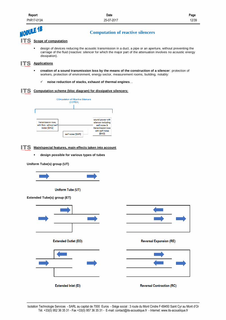
Scope of computation ▪ design of devices reducing the acoustic transmission in a duct, a pipe or an aperture, without preventing the
carriage of the fluid (reactive: silencer for which the major part of the attenuation involves no acoustic energy dissipation).
Applications ▪ creation of a sound transmission loss by the means of the construction of a silencer: protection of
workers, protection of environment, energy sector, measurement rooms, building, notably:
✓ noise reduction of stacks, exhaust of thermal engines…
Computation scheme (bloc diagram) for dissipative silencers:
Main/special features, main effects taken into account
▪ design possible for various types of tubes
Uniform Tube(s) group (UT)
Extended Tube(s) group (ET)
Computation of reactive silencers
ITS acoustique
ITS acoustique
ITS acoustique
ITS acoustique

Report Date Page
PhR17-013A 25-07-2017 13/39
Isolation Technologie Services - SARL au capital de 7000 Euros - Siège social : 3 route du Mont Cindre F-69450 Saint Cyr au Mont d’Or Tél. +33(0) 952 36 35 31 - Fax +33(0) 957 36 35 31 - E-mail: [email protected] - Internet: www.its-acoustique.fr
Side Tube(s) group (ST)
Transverse Tube(s) group (TT)
Variable Tube(s) group (VT)

Report Date Page
PhR17-013A 25-07-2017 14/39
Isolation Technologie Services - SARL au capital de 7000 Euros - Siège social : 3 route du Mont Cindre F-69450 Saint Cyr au Mont d’Or Tél. +33(0) 952 36 35 31 - Fax +33(0) 957 36 35 31 - E-mail: [email protected] - Internet: www.its-acoustique.fr
• preconfigured mountings involving long expansion chambers ✓ in-line chambers
EC1 = 1 expansion chamber
EC2 = 2 expansion chambers, with 1 or several connecting tubes (without overlapping between connecting tubes)
EC3 = 3 expansion chambers, with 1 or several connecting tubes, without connecting tubes overlapping
✓ chambers with side inlet
EC1SI = 1 expansion chamber, with side inlet
EC2SI = 2 expansion chambers, with 1 or several connecting tubes (without overlapping between connecting tubes),
with side inlet
EC3SI = 3 expansion chambers, with 1 or several connecting tubes (without overlapping between connecting tubes),
with side inlet
✓ chambers with side outlet
EC1SO = 1 expansion chamber, with side outlet
EC2SO = 2 expansion chambers, with 1 or several connecting tubes (without overlapping between connecting tubes),
with side outlet

Report Date Page
PhR17-013A 25-07-2017 15/39
Isolation Technologie Services - SARL au capital de 7000 Euros - Siège social : 3 route du Mont Cindre F-69450 Saint Cyr au Mont d’Or Tél. +33(0) 952 36 35 31 - Fax +33(0) 957 36 35 31 - E-mail: [email protected] - Internet: www.its-acoustique.fr
EC3SO = 3 expansion chambers, with 1 or several connecting tubes (without overlapping between connecting tubes),
with side outlet
✓ chambers with side inlet & with side outlet
EC1SISO = 1 expansion chamber, with side inlet, with side outlet
EC2SISO = 2 expansion chambers, with 1 or several connecting tubes (without overlapping between connecting tubes),
with side inlet, with side outlet
EC3SISO = 3 expansion chambers, with 1 or several connecting tubes (without overlapping between connecting tubes),
with side inlet, with side outlet
✓ chambers with overlapping tubes
EC1R1 = 1 expansion chamber, with overlapping tubes
EC1R2 = 1 expansion chamber, with 2 overlapping tubes in expansion chamber 1

Report Date Page
PhR17-013A 25-07-2017 16/39
Isolation Technologie Services - SARL au capital de 7000 Euros - Siège social : 3 route du Mont Cindre F-69450 Saint Cyr au Mont d’Or Tél. +33(0) 952 36 35 31 - Fax +33(0) 957 36 35 31 - E-mail: [email protected] - Internet: www.its-acoustique.fr
EC2R22 = 2 expansion chambers, with 2 overlapping tubes in expansion chamber 1, with 2 overlapping tubes in
expansion chamber 2
▪ preconfigured mountings involving short expansion chambers
EC1R1* = 1 expansion chamber, with 1 flow reversal
Main displayed results for the silencer (tables and graphs): ▪ total pressure loss
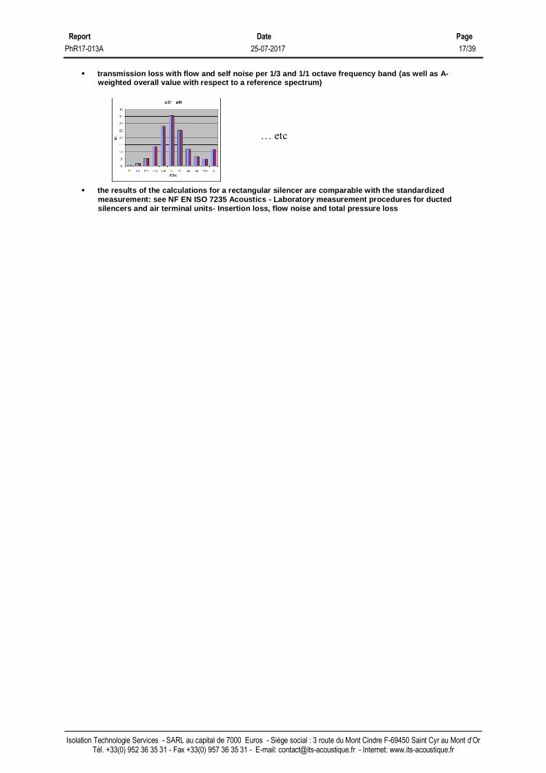
▪ transmission loss with flow per 1/3 & 1/1 octave frequency band (as well as A-weighted overall value
with respect to a reference spectrum)
▪ insertion loss with flow with a substitution duct per 1/3 & 1/1 octave frequency band (as well as A-
weighted overall value with respect to a reference spectrum)
▪ noise reduction with flow with an additional duct per 1/3 & 1/1 octave frequency band (as well as A-weighted overall value with respect to a reference spectrum)
▪ self noise (acoustic power of flow noise) per 1/1 octave frequency band (as well as A-weighted overall
value)
▪ A-weighted and not A-weighted acoustic power with silencer Lw1 (comparable with the not A-weighted acoustic power without silencer Lw0) per 1/1 octave frequency band
ITS acoustique
Report Date Page
PhR17-013A 25-07-2017 17/39
Isolation Technologie Services - SARL au capital de 7000 Euros - Siège social : 3 route du Mont Cindre F-69450 Saint Cyr au Mont d’Or Tél. +33(0) 952 36 35 31 - Fax +33(0) 957 36 35 31 - E-mail: [email protected] - Internet: www.its-acoustique.fr
▪ transmission loss with flow and self noise per 1/3 and 1/1 octave frequency band (as well as A-weighted overall value with respect to a reference spectrum)
▪ the results of the calculations for a rectangular silencer are comparable with the standardized measurement: see NF EN ISO 7235 Acoustics - Laboratory measurement procedures for ducted silencers and air terminal units- Insertion loss, flow noise and total pressure loss
… etc

Report Date Page
PhR17-013A 25-07-2017 18/39
Isolation Technologie Services - SARL au capital de 7000 Euros - Siège social : 3 route du Mont Cindre F-69450 Saint Cyr au Mont d’Or Tél. +33(0) 952 36 35 31 - Fax +33(0) 957 36 35 31 - E-mail: [email protected] - Internet: www.its-acoustique.fr
Scope of computation
▪ design of acoustic structures (products and construction systems) for which the shape of the surfaces from the one hand: facing the front atmosphere and from the other hand: at the rear are sufficiently close to a plane (for example: including corrugated plates and profiled claddings)
Applications ▪ creation of a sound reduction by the means of the construction of a (soundproofing) industrial
building/ booth/wall/screen with or without limiting the amplification of sound level on 1 or 2 sides of the acoustic protection (0,1 or 2 absorbing faces)
▪ limitation of the amplification of sound level on 1 or 2 sides of an acoustic protection: protection of workers, protection of environment, energy sector, measurement rooms, building, notably: ✓ construction of enclosures for various noisy equipments such as fans, aero condensers, engines,
gas turbines… ✓ construction of test benches… ✓ noise reduction of stacks, exhaust of gas turbines…
Computation scheme (bloc diagram)
Computation of plane partitions
ITS acoustique
ITS acoustique
ITS acoustique

Report Date Page
PhR17-013A 25-07-2017 19/39
Isolation Technologie Services - SARL au capital de 7000 Euros - Siège social : 3 route du Mont Cindre F-69450 Saint Cyr au Mont d’Or Tél. +33(0) 952 36 35 31 - Fax +33(0) 957 36 35 31 - E-mail: [email protected] - Internet: www.its-acoustique.fr
Main/special features, main effects taken into account
▪ design possible for multilayered acoustic structures (including: laminated absorbing materials)
B (resp. F, J) monolithic or B=B2+B1or B=B3+B2+B1 (resp. F=F2+F1 or F=F3+F2+F1; J=J2+J1 or J=J3+J2+J1) as shown below (zoom)
▪ for an acoustic structure including a porous medium (i.e. polyester, rock wool, basalt wool, glass wool, foam
…for which the engineering data can be referenced or air): behavior taken into account up to the microscopic scale in relation with the properties such as flow resistivity [cf. fig. 12] and other parameters for a locally reacting absorber
▪ effect of a laminated lining (for each layer: different properties such as flow resistivity [cf. fig. 13] or other different parameters): taken into account
▪ effect of a cloth (i.e. fabric, unwoven…for which the engineering data can be referenced): taken into account
[cf. fig. 14]
▪ for an acoustic structure including a perforated protection (i.e. perforated sheet with circular holes and square or hexagonal array, perforated sheet with square holes, infinite slots…for which the engineering data can be referenced): interaction of the protection with a porous medium at the front/at the rear taken into account [cf. fig. 15]
▪ for an acoustic structure including a thin plate (i.e. metal sheet, masonry, gypsum board, wood, glass …for basic plates): perforated plates taken into account, extensional damping (for example: steel sheet + viscoelastic) or constrained damping (for example steel sheet + viscoelastic + steel sheet) taken into account, orthotropic plates (for example: corrugated plates, ribbed plates, profiled cladding....) taken into account
▪ effect of temperature/of pressure taken into account [cf. fig. 16] [cf. fig. 17]
▪ effect of back (rear atmosphere or impervious rigid back) taken into account [cf. fig. 18]
item layer (*)
C, G porous medium (**)
D, H series cloth (**)
E, I series perforated protection (**)
B, F, J plate (***)
* selected among a library including for each kind of layer more than 20
referenced materials
**some cloths and some perforated protections can also be considered as
porous layers for the computation
***indeed: 1 or several identical plate(s) treated as a whole
B B B B2 B1 B3 B2 B1
F F F F2 F1 F3 F2 F1
J J J J2 J1 J3 J2 J1
when
monolithic
the plate can
be profiled
plate with
extensional
damping
plate with
constrained
damping
when
monolithic
the plate can
be perforated
basic
monolithic
plate
ITS acoustique

Report Date Page
PhR17-013A 25-07-2017 20/39
Isolation Technologie Services - SARL au capital de 7000 Euros - Siège social : 3 route du Mont Cindre F-69450 Saint Cyr au Mont d’Or Tél. +33(0) 952 36 35 31 - Fax +33(0) 957 36 35 31 - E-mail: [email protected] - Internet: www.its-acoustique.fr
Main displayed results for plates (only): ▪ engineering constants of thin plates equivalent to perforated plates, damped plates, orthotropic plates
▪ radiation ratio, (lowest & highest in case of orthotropic plates) critical frequency of thin plates & lowest natural frequency of thin plates (with the exception of plates with a constrained damping)
Fig. 12 Fig. 13
Fig. 14 Fig. 15
Fig. 16 Fig. 17
absorption coefficient at normal incidence alpha0
0,00
0,20
0,40
0,60
0,80
1,00
1,20
1 10 100 1000 10000 100000f(Hz)
alp
ha0
impervious rigid back atmospheric back
absorption coefficient at normal incidence alpha0
0,00
0,20
0,40
0,60
0,80
1,00
1,20
1 10 100 1000 10000 100000
f(Hz)
alp
ha0
without with
absorption coefficient at normal incidence alpha0
0,00
0,20
0,40
0,60
0,80
1,00
1,20
1 10 100 1000 10000 100000f(Hz)
alp
ha0
without with
absorption coefficient at normal incidence alpha0
0,00
0,20
0,40
0,60
0,80
1,00
1,20
1 10 100 1000 10000 100000f(Hz)
alp
ha0
100kPa 200kPa 400kPa
absorption coefficient at normal incidence alpha0
0,00
0,20
0,40
0,60
0,80
1,00
1,20
1 10 100 1000 10000 100000f(Hz)
alp
ha0
8kNsm-4
12kNsm-4
16kNsm-4
24kNsm-4
48kNsm-4
72kNsm-4
absorption coefficient at normal incidence alpha0
0,00
0,10
0,20
0,30
0,40
0,50
0,60
0,70
0,80
0,90
1,00
1 10 100 1000 10000 100000f(Hz)
alp
ha0
12kNsm-4
72kNsm-4
mix
absorption coefficient at normal incidence alpha0
0,00
0,20
0,40
0,60
0,80
1,00
1,20
1 10 100 1000 10000 100000f(Hz)
alp
ha0
20 °C 300 °C 600 °C
Fig. 18
ITS
acoustique

Report Date Page
PhR17-013A 25-07-2017 21/39
Isolation Technologie Services - SARL au capital de 7000 Euros - Siège social : 3 route du Mont Cindre F-69450 Saint Cyr au Mont d’Or Tél. +33(0) 952 36 35 31 - Fax +33(0) 957 36 35 31 - E-mail: [email protected] - Internet: www.its-acoustique.fr
Main displayed results for the whole acoustic structure (tables and graphs):
▪ absorption coefficient at normal incidence: α0, absorption coefficient for a statistic incidence: αstat, Sabine’s factor: αsab per 1/3 and 1/1 octave frequency band, unique index αw (figure below: for a porous
medium with an impervious rigid back)
▪ sound reduction index with sound leaks: Rstat per 1/3 and 1/1 octave frequency band, unique index
Rw and correction terms (for a single leaf, or a double leaf or a triple leaf partition with 0 % coupling) (figure below: for a single isotropic thin plate with an atmospheric back)
▪ sound reduction index for a double-leaf partition with connections between thin plates with sound
leaks: Rstat per 1/3 and 1/1 octave frequency band, unique index Rw and correction terms
▪ the results of the calculations are comparable with the standardized measurement: (in case of
atmospheric back) see NF EN ISO 10140-2 Acoustics. Laboratory measurement of sound insulation of building elements. Measurement of airborne sound insulation and (in case of rigid impervious back) see NF EN ISO 354 Acoustics – Measurement of sound absorption in a reverberation room and also ISO 10534-1 Acoustics – Determination of sound absorption coefficient and impedance in impedance tubes – Part 1: Method using standing wave ratio.
▪ acoustic power with the partition Lw1 (comparable with the acoustic power without partition Lw0) per
1/1 octave frequency band
… etc
ITS acoustique
Report Date Page
PhR17-013A 25-07-2017 22/39
Isolation Technologie Services - SARL au capital de 7000 Euros - Siège social : 3 route du Mont Cindre F-69450 Saint Cyr au Mont d’Or Tél. +33(0) 952 36 35 31 - Fax +33(0) 957 36 35 31 - E-mail: [email protected] - Internet: www.its-acoustique.fr
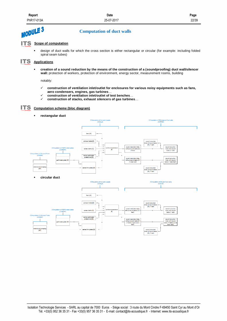
Scope of computation
▪ design of duct walls for which the cross section is either rectangular or circular (for example: including folded spiral seam tubes)
Applications ▪ creation of a sound reduction by the means of the construction of a (soundproofing) duct wall/silencer
wall: protection of workers, protection of environment, energy sector, measurement rooms, building
notably: ✓ construction of ventilation inlet/outlet for enclosures for various noisy equipments such as fans,
aero condensers, engines, gas turbines… ✓ construction of ventilation inlet/outlet of test benches… ✓ construction of stacks, exhaust silencers of gas turbines…
Computation scheme (bloc diagram)
▪ rectangular duct
▪ circular duct
Computation of duct walls
ITS acoustique
ITS acoustique
ITS acoustique

Report Date Page
PhR17-013A 25-07-2017 23/39
Isolation Technologie Services - SARL au capital de 7000 Euros - Siège social : 3 route du Mont Cindre F-69450 Saint Cyr au Mont d’Or Tél. +33(0) 952 36 35 31 - Fax +33(0) 957 36 35 31 - E-mail: [email protected] - Internet: www.its-acoustique.fr
Main/special features, main effects taken into account
▪ design possible for 1 leaf acoustic structures (for the present revision of the software), with a rectangular or circular cross section (including folded spiral-seam ducts)
B monolithic or B=B2+B1as shown below (zoom)
▪ for an acoustic structure including a thin plate (i.e. metal sheet, masonry, gypsum board, wood, glass …for
basic plates): perforated plates taken into account, extensional damping (for example: steel sheet + viscoelastic) or constrained damping (for example steel sheet + viscoelastic + steel sheet) taken into account, orthotropic plates (for example: corrugated plates, ribbed plates, profiled cladding....) taken into account
▪ effect of temperature/of pressure taken into account
Main displayed results for the whole acoustic structure (tables and graphs):
▪ sound reduction index with sound leaks: Rstat per 1/1 octave frequency band, unique index Rw and correction terms (for a single leaf) (figure below: for a steel pipe with an atmospheric back)
▪ the obtained results are not comparable with standardized measurement due to the lack of documents formalizing corresponding measurement procedures
item layer (*)
B plate (***) * selected among a library including for each kind of layer more than 20
referenced materials
***indeed: 1 or several identical plate(s) treated as a whole
… etc
B B B2 B1
plate with
extensional
damping
when
monolithic
the plate can
be perforated
basic
monolithic
plate
ITS acoustique
ITS acoustique

Report Date Page
PhR17-013A 25-07-2017 24/39
Isolation Technologie Services - SARL au capital de 7000 Euros - Siège social : 3 route du Mont Cindre F-69450 Saint Cyr au Mont d’Or Tél. +33(0) 952 36 35 31 - Fax +33(0) 957 36 35 31 - E-mail: [email protected] - Internet: www.its-acoustique.fr
Scope of computation
▪ design of components of a duct system with a constant cross section being either rectangular or circular Applications ▪ consideration of the sound reduction of the components of duct systems on the occasion of the
evaluation of the sound levels at the extremity (mouth) of duct systems: protection of workers, protection of environment, energy sector, measurement rooms, building
notably: ✓ construction of air conditioning systems as well as ventilation systems for enclosures for various
noisy equipments necessitating duct systems with horizontal or vertical duct sections (stacks ) such as fans, engines, gas turbines…
✓ construction of ventilation systems for auxiliary premises or buildings, test benches…
Computation scheme (bloc diagram)
Main/special features, main effects taken into account
▪ design possible with a rectangular or circular cross section (including folded spiral seam tubes) ▪ design possible for thin ducts (e.g. for conditioning systems applications) as well as for thick ducts
(e.g. for stacks)
Main displayed results (tables):
▪ insertion loss without self noise of straight duct section Di’ per 1/1 octave frequency band (as well as A-weighted overall value with respect to a reference spectrum)
▪ self noise of straight duct section Lw per 1/1 octave frequency band (as well as A-weighted overall value)
▪ sound power level downstream of considered straight duct section Lw1 per 1/1 octave frequency band (as well as A-weighted overall value)
▪ insertion loss with self noise of straight duct section Di per 1/1 octave frequency band (as well as A-weighted overall value with respect to a reference spectrum) (figure below: for a rectangular duct)
▪ the obtained results are not comparable with standardized measurement due to the lack of documents formalizing corresponding measurement procedures
Computation of straight ducts
ITS acoustique
ITS acoustique
ITS acoustique
ITS acoustique
ITS acoustique

Report Date Page
PhR17-013A 25-07-2017 25/39
Isolation Technologie Services - SARL au capital de 7000 Euros - Siège social : 3 route du Mont Cindre F-69450 Saint Cyr au Mont d’Or Tél. +33(0) 952 36 35 31 - Fax +33(0) 957 36 35 31 - E-mail: [email protected] - Internet: www.its-acoustique.fr
Scope of computation
▪ design of components of a duct system with a cross section being either rectangular or circular Applications ▪ consideration of the sound emission of the components of duct systems on the occasion of the
evaluation of the sound levels due to noise transmission trough the duct walls: protection of workers, protection of environment, energy sector, measurement rooms, building
notably: ✓ construction of air conditioning systems as well as ventilation systems for enclosures for various
noisy equipments necessitating duct systems with horizontal or vertical duct sections (stacks ) such as fans, engines, gas turbines…
✓ construction of ventilation systems for auxiliary premises or buildings, test benches…
Computation scheme (bloc diagram)
• Bloc diagram in case of a silencer
Computation of break-out noise
ITS acoustique
ITS acoustique
ITS acoustique

Report Date Page
PhR17-013A 25-07-2017 26/39
Isolation Technologie Services - SARL au capital de 7000 Euros - Siège social : 3 route du Mont Cindre F-69450 Saint Cyr au Mont d’Or Tél. +33(0) 952 36 35 31 - Fax +33(0) 957 36 35 31 - E-mail: [email protected] - Internet: www.its-acoustique.fr
• Bloc diagram in case of an empty duct
Main/special features, main effects taken into account
▪ design possible either for straight ducts (with a rectangular cross section, or with a circular cross section - including folded spiral seam ducts) or for silencers
▪ design possible for thin duct casings (e.g. for conditioning systems applications) as well as for thick ducts casings (e.g. for stacks)
Main displayed results (tables):
▪ sound power level transmitted by the walls of duct / of silencer Lwout per 1/1 octave frequency band (as well as A-weighted overall value) (figure below: for a rectangular duct)
▪ the obtained results are not comparable with standardized measurement due to the lack of documents
formalizing corresponding measurement procedures
ITS acoustique
ITS acoustique

Report Date Page
PhR17-013A 25-07-2017 27/39
Isolation Technologie Services - SARL au capital de 7000 Euros - Siège social : 3 route du Mont Cindre F-69450 Saint Cyr au Mont d’Or Tél. +33(0) 952 36 35 31 - Fax +33(0) 957 36 35 31 - E-mail: [email protected] - Internet: www.its-acoustique.fr
Scope of computation
▪ design of components of a duct system with a cross section being rectangular (with a width being constant, with a height at duct section inlet being different from height at duct section outlet)
Applications ▪ consideration of the sound emission of the components of duct systems on the occasion of the
evaluation of the sound levels due to noise transmission trough the duct walls: protection of workers, protection of environment, energy sector, measurement rooms, building
notably: ✓ construction of air conditioning systems as well as ventilation systems for enclosures for various
noisy equipments necessitating duct systems with horizontal or vertical duct sections (stacks ) such as fans, engines, gas turbines…
✓ construction of ventilation systems for auxiliary premises or buildings, test benches…
Computation scheme (bloc diagram)
• Bloc diagram in case of an empty duct: as in section 5 (downstream step to be considered only)
Main/special features, main effects taken into account
▪ design possible for ducts with a rectangular cross section ▪ design possible for thin duct casings (e.g. for conditioning systems applications) as well as for thick
ducts casings (e.g. for stacks)
Main displayed results (tables):
▪ sound power level transmitted by the walls of duct / of silencer Lwout per 1/1 octave frequency band
(as well as A-weighted overall value) (figure below: for a rectangular duct)
▪ the obtained results are not comparable with standardized measurement due to the lack of documents
formalizing corresponding measurement procedures
Computation of break-out noise of ducts with variable cross section
ITS acoustique
ITS acoustique
ITS acoustique
ITS acoustique
ITS acoustique
Report Date Page
PhR17-013A 25-07-2017 28/39
Isolation Technologie Services - SARL au capital de 7000 Euros - Siège social : 3 route du Mont Cindre F-69450 Saint Cyr au Mont d’Or Tél. +33(0) 952 36 35 31 - Fax +33(0) 957 36 35 31 - E-mail: [email protected] - Internet: www.its-acoustique.fr
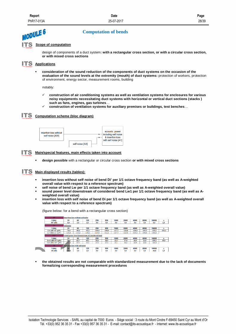
Scope of computation
design of components of a duct system: with a rectangular cross section, or with a circular cross section, or with mixed cross sections
Applications ▪ consideration of the sound reduction of the components of duct systems on the occasion of the
evaluation of the sound levels at the extremity (mouth) of duct systems: protection of workers, protection of environment, energy sector, measurement rooms, building
notably: ✓ construction of air conditioning systems as well as ventilation systems for enclosures for various
noisy equipments necessitating duct systems with horizontal or vertical duct sections (stacks ) such as fans, engines, gas turbines…
✓ construction of ventilation systems for auxiliary premises or buildings, test benches…
Computation scheme (bloc diagram)
Main/special features, main effects taken into account
▪ design possible with a rectangular or circular cross section or with mixed cross sections
Main displayed results (tables):
▪ insertion loss without self noise of bend Di’ per 1/1 octave frequency band (as well as A-weighted
overall value with respect to a reference spectrum) ▪ self noise of bend Lw per 1/1 octave frequency band (as well as A-weighted overall value) ▪ sound power level downstream of considered bend Lw1 per 1/1 octave frequency band (as well as A-
weighted overall value) ▪ insertion loss with self noise of bend Di per 1/1 octave frequency band (as well as A-weighted overall
value with respect to a reference spectrum) (figure below: for a bend with a rectangular cross section)
▪ the obtained results are not comparable with standardized measurement due to the lack of documents formalizing corresponding measurement procedures
Computation of bends
ITS acoustique
ITS acoustique
ITS acoustique
ITS acoustique
ITS acoustique

Report Date Page
PhR17-013A 25-07-2017 29/39
Isolation Technologie Services - SARL au capital de 7000 Euros - Siège social : 3 route du Mont Cindre F-69450 Saint Cyr au Mont d’Or Tél. +33(0) 952 36 35 31 - Fax +33(0) 957 36 35 31 - E-mail: [email protected] - Internet: www.its-acoustique.fr
Scope of computation
design of components of a duct system: with a rectangular cross section, or with a circular cross section
Applications ▪ consideration of the sound reduction of the components of duct systems on the occasion of the
evaluation of the sound levels at the extremity (mouth) of duct systems: protection of workers, protection of environment, energy sector, measurement rooms, building
notably: ✓ construction of air conditioning systems as well as ventilation systems for enclosures for various
noisy equipments necessitating duct systems with horizontal or vertical duct sections (stacks ) such as fans, engines, gas turbines…
✓ construction of ventilation systems for auxiliary premises or buildings, test benches…
Computation scheme (bloc diagram)
Main/special features, main effects taken into account
▪ design possible with a rectangular or circular cross section
Main displayed results (tables):
▪ insertion loss without self noise Di’ per 1/1 octave frequency band (as well as A-weighted overall value
with respect to a reference spectrum) ▪ self noise Lw per 1/1 octave frequency band (as well as A-weighted overall value) ▪ sound power level downstream Lw1 per 1/1 octave frequency band (as well as A-weighted overall
value) ▪ insertion loss with self noise of bend Di per 1/1 octave frequency band (as well as A-weighted overall
value with respect to a reference spectrum) (figure below: for a mouth with a circular cross section)
▪ the obtained results are not comparable with standardized measurement due to the lack of documents formalizing corresponding measurement procedures
Computation of nozzle reflection
ITS acoustique
ITS acoustique
ITS acoustique
ITS acoustique
ITS acoustique

Report Date Page
PhR17-013A 25-07-2017 30/39
Isolation Technologie Services - SARL au capital de 7000 Euros - Siège social : 3 route du Mont Cindre F-69450 Saint Cyr au Mont d’Or Tél. +33(0) 952 36 35 31 - Fax +33(0) 957 36 35 31 - E-mail: [email protected] - Internet: www.its-acoustique.fr
Scope of computation
prediction of the sound impact of duct systems including components such as silencers (dissipative or resonant), straight ducts sections, bends with a rectangular cross section, or with a circular cross section, or with mixed cross sections (for some components).
Applications ▪ consideration of the sound reduction of the components of duct systems on the occasion of the
evaluation of the sound levels at the extremity (mouth) of duct systems as well as sound levels due to noise transmission trough duct walls: protection of workers, protection of environment, energy sector, measurement rooms, building
notably: ✓ construction of air conditioning systems as well as ventilation systems for enclosures for various
noisy equipments necessitating duct systems with horizontal or vertical duct sections (stacks ) such as fans, engines, gas turbines…
✓ construction of ventilation systems for auxiliary premises or buildings, test benches…
Computation scheme (bloc diagram)
▪ Bloc diagram regarding the longitudinal noise propagation i.e. for the computation of the sound
power level downstream of the duct system:
Note: this bloc diagram is used within a waterfall computation for all the components of the system,
referred to as C1 to C10)
[C1] [C2] [C3] [C4] [C5] [C6] [C7] [C8] [C9] [C10]
▪ Bloc diagram regarding the transverse noise propagation i.e. for the computation of the sound
power level transmitted by the walls of the duct system:
[C1] [C2] [C3] [C4] [C5] [C6] [C7] [C8] [C9] [C10]
Main/special features, main effects taken into account
▪ design possible for silencers (dissipative or resonant), straight ducts sections, bends with a
rectangular cross section, or with a circular cross section, or with mixed cross sections (for some components)
▪ design possible for thin duct casings (e.g. for conditioning systems applications) as well as for thick ducts casings (e.g. for stacks)
▪ design possible in case of acoustic performance computed with software SILDIS or not (Bring-Your-Own approach) or mixed approach
Main displayed results (tables):
Computation of sound impact of a duct system
ITS acoustique
ITS acoustique
ITS acoustique
ITS acoustique
ITS acoustique
Lw0 Lw1calc
Lw0
Lwoutcalc

Report Date Page
PhR17-013A 25-07-2017 31/39
Isolation Technologie Services - SARL au capital de 7000 Euros - Siège social : 3 route du Mont Cindre F-69450 Saint Cyr au Mont d’Or Tél. +33(0) 952 36 35 31 - Fax +33(0) 957 36 35 31 - E-mail: [email protected] - Internet: www.its-acoustique.fr
▪ Main displayed results regarding the longitudinal noise propagation i.e. for the computation of the sound power level downstream of the duct system:
▪ sound power level downstream of each considered component of the duct system Lw1 per 1/1
octave frequency band (as well as A-weighted overall value) ▪ insertion loss with self noise of each considered component of the duct system Di per 1/1 octave
frequency band (as well as A-weighted overall value with respect to a reference spectrum) ▪ sound power level of the silenced source Lw1calc per 1/1 octave frequency band (as well as A-
weighted overall value) ▪ sound pressure level at a specified distance of the silenced source Lp1calc per 1/1 octave
frequency band (as well as A-weighted overall value) (table below: for a silencer + a bend + a duct with a circular cross section)
▪ Main displayed results regarding the transverse noise propagation i.e. for the computation of the sound power level transmitted by the walls of the duct system:
▪ sound pressure level at a specified distance of each component Lpoutcalc per 1/1 octave
frequency band (as well as A-weighted overall value)
(figure below: for a silencer + a bend + a duct with a circular cross section)

Report Date Page
PhR17-013A 25-07-2017 32/39
Isolation Technologie Services - SARL au capital de 7000 Euros - Siège social : 3 route du Mont Cindre F-69450 Saint Cyr au Mont d’Or Tél. +33(0) 952 36 35 31 - Fax +33(0) 957 36 35 31 - E-mail: [email protected] - Internet: www.its-acoustique.fr
Scope of computation
prediction of the sound impact of piping & duct systems ends
Applications ▪ evaluation of the noise emissions at the extremity (mouth) of piping & duct systems: protection of
workers, protection of environment, energy sector, measurement rooms, building
notably: ✓ stacks for fans, engines, gas turbines… ✓ industrial process exhausts…
Computation scheme (bloc diagram)
▪ Not applicable
Main/special features, main effects taken into account
▪ angle with respect to stack axis ▪ stack radius ▪ speed of sound
Main displayed results (tables): ▪ directivity index (1/3 & 1/1 octave bands)
(screenshot below: for a an exhaust duct with small diameter)
Prediction of stack directivity
ITS acoustique
ITS acoustique
ITS acoustique
ITS acoustique
ITS acoustique

Report Date Page
PhR17-013A 25-07-2017 33/39
Isolation Technologie Services - SARL au capital de 7000 Euros - Siège social : 3 route du Mont Cindre F-69450 Saint Cyr au Mont d’Or Tél. +33(0) 952 36 35 31 - Fax +33(0) 957 36 35 31 - E-mail: [email protected] - Internet: www.its-acoustique.fr
Scope of computation
prediction of the attenuation of sound in relation to propagation path through atmosphere
Applications ▪ evaluation of the noise impact of sound sources outdoor: protection of workers, protection of environment,
energy sector in particular ▪ room acoustics: protection of workers, measurement rooms, acoustic comfort in buildings
Computation scheme (bloc diagram)
▪ Not applicable
Main/special features, main effects taken into account
▪ ambient atmospheric pressure ▪ ambient atmospheric temperature ▪ relative humidity ▪ propagation path length
Main displayed results (tables): ▪ atmospheric attenuation coefficient (1/3 & 1/1 octave bands) ▪ atmospheric attenuation for a given propagation path (1/3 & 1/1 octave bands)
(screenshot below: example)
Prediction of atmospheric sound absorption
ITS acoustique
ITS acoustique
ITS acoustique
ITS acoustique
ITS acoustique

Report Date Page
PhR17-013A 25-07-2017 34/39
Isolation Technologie Services - SARL au capital de 7000 Euros - Siège social : 3 route du Mont Cindre F-69450 Saint Cyr au Mont d’Or Tél. +33(0) 952 36 35 31 - Fax +33(0) 957 36 35 31 - E-mail: [email protected] - Internet: www.its-acoustique.fr
Scope of computation
prediction of the external sound pressure level generated in a control valve and within adjacent pipe expanders by the flow of compressible fluids, considering only single-phase dry gases and vapours and based on the perfect gas laws
Applications ▪ evaluation of the noise impact of industrial processes exhausts outdoor: protection of workers, protection
of environment, energy sector in particular
Computation scheme (bloc diagram)
▪ Not applicable
Main/special features, main effects taken into account
▪ control valves parameters ▪ process parameters
Main displayed results (tables): ▪ sound power level (OA) ▪ generated peak frequency ▪ sound power level (1/3 & 1/1 octave bands)
▪ Mach number at valve outlet
(table below: example)
Prediction of control valves aerodynamic noise
ITS acoustique
ITS acoustique
ITS acoustique
ITS acoustique
ITS acoustique

Report Date Page
PhR17-013A 25-07-2017 35/39
Isolation Technologie Services - SARL au capital de 7000 Euros - Siège social : 3 route du Mont Cindre F-69450 Saint Cyr au Mont d’Or Tél. +33(0) 952 36 35 31 - Fax +33(0) 957 36 35 31 - E-mail: [email protected] - Internet: www.its-acoustique.fr
Scope of computation
prediction of the external sound levels generated by a jet i.e. a fluid flow between a high pressure zone & a low pressure zone: either at extremities of a component of a piping system (excluding control valves, including safety valves) or at its end (discharge) for a compressible fluid, considering only single-phase dry gases and vapours and based on the perfect gas laws
Applications ▪ evaluation of the noise impact of gas discharges from safety valves or pipes outdoor: protection of
workers, protection of environment, energy sector in particular
Computation scheme (bloc diagram)
▪ Not applicable
Main/special features, main effects taken into account
▪ high pressure zone parameters ▪ low pressure zone parameters ▪ piping component parameters
Main displayed results (tables): ▪ sound power level (OA) ▪ generated peak frequency ▪ sound power level (1/3 & 1/1 octave bands)
(table below: example)
Prediction of jet noise (including safety valves noise)
ITS acoustique
ITS acoustique
ITS acoustique
ITS acoustique
ITS acoustique
Report Date Page
PhR17-013A 25-07-2017 36/39
Isolation Technologie Services - SARL au capital de 7000 Euros - Siège social : 3 route du Mont Cindre F-69450 Saint Cyr au Mont d’Or Tél. +33(0) 952 36 35 31 - Fax +33(0) 957 36 35 31 - E-mail: [email protected] - Internet: www.its-acoustique.fr
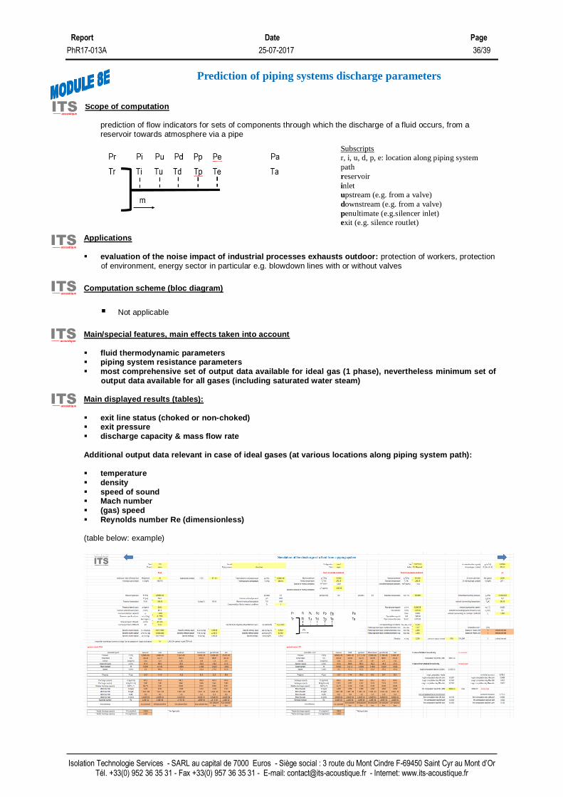
Scope of computation
prediction of flow indicators for sets of components through which the discharge of a fluid occurs, from a reservoir towards atmosphere via a pipe
Applications ▪ evaluation of the noise impact of industrial processes exhausts outdoor: protection of workers, protection
of environment, energy sector in particular e.g. blowdown lines with or without valves
Computation scheme (bloc diagram)
▪ Not applicable
Main/special features, main effects taken into account
▪ fluid thermodynamic parameters ▪ piping system resistance parameters ▪ most comprehensive set of output data available for ideal gas (1 phase), nevertheless minimum set of
output data available for all gases (including saturated water steam)
Main displayed results (tables):
▪ exit line status (choked or non-choked) ▪ exit pressure ▪ discharge capacity & mass flow rate
Additional output data relevant in case of ideal gases (at various locations along piping system path):
▪ temperature ▪ density
▪ speed of sound ▪ Mach number ▪ (gas) speed ▪ Reynolds number Re (dimensionless)
(table below: example)
Prediction of piping systems discharge parameters
ITS acoustique
ITS acoustique
ITS acoustique
ITS acoustique
ITS acoustique
Subscripts
r, i, u, d, p, e: location along piping system
path
reservoir
inlet
upstream (e.g. from a valve)
downstream (e.g. from a valve)
penultimate (e.g.silencer inlet)
exit (e.g. silence routlet)

Report Date Page
PhR17-013A 25-07-2017 37/39
Isolation Technologie Services - SARL au capital de 7000 Euros - Siège social : 3 route du Mont Cindre F-69450 Saint Cyr au Mont d’Or Tél. +33(0) 952 36 35 31 - Fax +33(0) 957 36 35 31 - E-mail: [email protected] - Internet: www.its-acoustique.fr
Scope of computation
room acoustics design study
Applications ▪ consideration of the impact of reverberation on the acoustical quality of premises: protection of workers,
protection of environment, energy sector, measurement rooms, building
notably: ✓ soundproofing industrial buildings ✓ large machine enclosures ✓ test benches ✓ premises dedicated to technical equipments ✓ room intended to house activities such as catering, education, sports and recreation
Computation scheme (bloc diagram)
Main/special features, main effects taken into account
▪ design possible with a rectangular shape or with different shapes ▪ scattering effects accounted for premises with a rectangular shape ▪ fitting accounted ▪ atmospheric absorption accounted
Main displayed results (tables):
▪ reverberation time per 1/1 octave frequency band (screenshot below: for a rectangular room)
Computation of sound decay in enclosed spaces
ITS acoustique
ITS acoustique
ITS acoustique
ITS acoustique
ITS acoustique

Report Date Page
PhR17-013A 25-07-2017 38/39
Isolation Technologie Services - SARL au capital de 7000 Euros - Siège social : 3 route du Mont Cindre F-69450 Saint Cyr au Mont d’Or Tél. +33(0) 952 36 35 31 - Fax +33(0) 957 36 35 31 - E-mail: [email protected] - Internet: www.its-acoustique.fr
▪ the obtained results are comparable with standardized measurement NF EN ISO 3382-2 Acoustics - Measurement of room acoustics parameters- Part 2: reverberation time in ordinary rooms.

Report Date Page
PhR17-013A 25-07-2017 39/39
Isolation Technologie Services - SARL au capital de 7000 Euros - Siège social : 3 route du Mont Cindre F-69450 Saint Cyr au Mont d’Or Tél. +33(0) 952 36 35 31 - Fax +33(0) 957 36 35 31 - E-mail: [email protected] - Internet: www.its-acoustique.fr
Scope of computation
working places rooms acoustics design study
Applications
▪ evaluation of acoustical comfort of tertiary premises: protection of workers
Computation scheme (bloc diagram)
Main/special features, main effects taken into account
▪ room dimensions ▪ average height of screens & storage units ▪ ceiling absorption ▪ apparent furnishing absorption
Main displayed results (tables):
▪ spatial decay rate of speech ▪ A-weighted sound pressure level of speech at a distance of 4 m ▪ spatial decay of speech (A-weighted sound pressure level of speech at a variable distance)
(screenshot below: example)
Some of the obtained results are comparable with standardized measurement NF EN ISO 3382-3 Acoustics -Measurement of room acoustics parameters- Part 3: Open plan offices.
Prediction of sound spatial decay in open-plan offices
ITS acoustique
ITS acoustique
ITS acoustique
ITS acoustique
ITS acoustique