technological properties of direct-quenched structural ... · method is gas shielded arc welding...
TRANSCRIPT

Ruukki is a metal expert you can rely on all the way, whenever you need metal based materials, components, systems or total solutions. We constantly develop our product range and operating models to match your needs.
1
Ruukki is a metal expert you can rely on all the way, whenever you need metal based materials, components, systems or total solutions. We constantly develop our product range and operating models to match your needs.
Technological properties of direct-quenched structural steels with yield strengths 900 – 960 MPa as cut lengths and hollow sections
M Hemmilä, A Hirvi, J Kömi, R Laitinen, M Lehtinen, P Mikkonen, D Porter, J Savola, S Tihinen Rautaruukki Oyj, Ruukki Metals, Finland
1

Technological properties of direct-quenched structural steels with yield strengths 900 – 960 MPa as cut lengths and hollow sections
• Minimum specified tensile and impact properties Table 2
Optimgrade
Rp0.2MPa
RmMPa
A%
Charpy V, longitudinal, -40 °CJ/cm2
900 QC 900 950 8 34960 QC 960 1000 7 34
• Chemical composition limits and carbon equivalent values (wt. %) Table 1
Optim grade
Cmax
Simax
Mnmax
Pmax
Smax
Timax
CEVtypical
900 QC 0.10 0.25 1.15 0.020 0.010 0.07 0.51960 QC 0.11 0.25 1.20 0.020 0.010 0.07 0.52
Additionally Al, Nb, V, Cr, Mo or B are used either singly or in combination. CEV = C+Mn/6+ (Cr+Mo+V)/5+ (Cu+Ni)/15
• AbstractThe technological properties of direct quenched ultra-high strength steels with minimum specified yield strengths of 900 and 960 MPa are described and compared to conventional quenched and tempered steels, e.g. S960QL. It is shown that by optimising the levelling process 2.5 – 8 mm thick cut lengths can be made from the hot strip mill coils with good flatness and low levels of residual stress. At such high strength levels, brake press forming requires special attention: the conventional way of calculating force requirements leads to underestimations and spring-back is large. Due to their low carbon content, welding can be done without preheat and the toughness of the heat affected zone is good. Heat affected zone softening occurs but its magnitude can be controlled and taken into account in structural design. The steels are well suited to roll form-ing and high frequency welding. The soft decarburized zone at the centre line of the high frequency weld has been shown to have no detrimental effect on the overall performance of hollow structural sections. A weather resistant version with a yield strength of 960 MPa has been made by modifying the steel chemistry.
• KeywordsDirect quenching, strength, toughness, levelling, weld-ing, brake press forming, roll forming, weather resis-tance.
• IntroductionUltra-high strength steels with minimum specific yield strengths of 900 and 960 MPa with the proprietary names Optim 900 QC, Optim 960 QC and Optim 960 QCW are made using hot strip rolling and direct quenching followed by leveling and cutting to plates with thicknesses in the range 2.5 – 8 mm [1, 2]. Due to the combination of thermomechanical rolling and low carbon content, good combinations of strength and toughness are achieved without tempering. The steels are typically used in light-weight mobile structures like containers as well as booms, arms and other structural members of mobile lifting equipment. The purpose of this article is to give the results of recent research into the technological properties of the steels, i.e. internal stresses, bendabil-ity, weldability and corrosion resistance.
• 1. Steel composition, mechanical properties & microstructureInformation regarding the chemical composition and me-chanical properties of the QC grades is given in Tables 1 and 2. The low carbon content imparts high impact toughness after direct quenching to bainite / martensite thereby eliminating the need for tempering. It also en-sures good weldability without the need for preheating. Manganese is limited to minimize centre-line segrega-tion and silicon is limited to give a good surface quality. Suitable bainite / martensite hardenability is achieved by controlling the contents of elements like Cr, Cu, Ni, Mo, Nb, V and B.
22

Technological properties of direct-quenched structural steels with yield strengths 900 – 960 MPa as cut lengths and hollow sections
Fig. 1 shows a typical microstructure for Optim 960 QC. The bainite component of the microstructure is mainly upper bainite, but some regions of lower bainite are also present. Martensite in these steels is partially autotem-pered due to the low carbon content and relatively high martensite start temperature.
• 2. Flatness and internal stressesPlate flatness is an important property for steel process-ing workshops; not only flatness in the delivery condi-tion, but also after cutting. Unwanted shape changes cause extra work and costs in the manufacturing process. Depending on the flatness of the strip before coiling and the levelling process parameters, plates may contain internal stresses that cause shape changes during cutting even if the plate is flat in the delivery condition. The achievement of flat stress-free plates becomes ever more demanding as the strength of the steel increases and the thickness decreases.
The effect of residual stresses and shape changes has been tested by laser cutting narrow strips 50 x 1000 mm from plates with different yield strengths and thickness-es. The strips were cut parallel to the rolling direction at regular intervals across the width of the plate. The amount of bending was taken as the maximum distance between the strip and a flat table when the strip ends were placed in contact with the table. A laser cut plate is shown in Fig. 2. Measured amounts of bending are shown in Fig. 3, where positive and negative values denote bending towards opposite plate surfaces. The material with a yield strength of 700 MPa and thickness 10 mm was levelled with two plastic deformation ratios. In both cases, the plates were flat before laser cutting, but in one case insufficient plastification during levelling has resulted in severe bending after cutting. The results for 6 mm thick Optim 960 QC show that with correct levelling parameters it is possible to get dead flat plates without internal stresses despite the high strength level.
• 3. Brake press formingBrake press forming of ultra-high strength steel requires special attention. The required bending force and the level of springback increase as the strength of the steel increases. Optim 900 and 960 QC steels require minimum inside bending radii of several times the material thickness, normally not less than three times, to be ensure crack-free bending. When bending to large inside radii more material needs to be bent using large-nosed punches, which also increases springback. Even if a large radius is used in air bending, the strain is not evenly distributed: in some cases there can be high strain areas in the middle of the bend, as shown for example in Fig. 4. In such cases the punch loses
Fig. 1. Field Emission Scanning Electron Microscope image of nital-etched Optim 960 QC. Bar length bottom right is 1 µm.
Fig. 2. Release of internal stresses caused by laser cutting
Fig. 3. Bending of 50 x 1000 mm strips laser cut from flat plates with yield strengths 700 and 960 MPa.
33

Technological properties of direct-quenched structural steels with yield strengths 900 – 960 MPa as cut lengths and hollow sections
contact with the steel at the centre of the bend and a non-uniform internal bend radius results. This is accom-panied by the appearance of a surface corrugations or even small surface cracks.
Elastic pads like that shown in Fig. 5 can be used to advantage to produce more uniform and smaller bend radii. Depending on the tools used, the bending force is, however, increased by at least a 50%. Tests have shown that by using an elastic pad, it is possible to avoid some geometrical errors and obtain internal bend radii that are up to 50% smaller than are possible with air bending, as shown in Table 3, for example.
It is commonly assumed that the bending force (F) needed to flange a steel plate in air can be calculated using the following formula:
F = C Rm b t2 / W
where Rm is tensile strength, t is plate thickness, C is a constant whose magnitude is 1.2 – 1.5, b is the bend length and W is the die gap. However, when using ultra-high strength steels that require large punch radii, this way of calculating force requirements leads to an under-estimation because the size of the punch is not included to the formula: a larger punch deforms more material, which in turn raises the required force.
Fig. 4. Hardness profile of Optim 960 QC with 90 degree bending angle. Average hardness of the base material is 350 HV1. Average hardness within marked square (middle of bend) 404 HV1.
Fig. 5. Elastic pad and die.
• 4. Roll forming The roll forming of Optim 900 QC has been tested on the production line of Ruukki’s Toijala works. The trials were made using 4 mm thick material slit into 382 mm wide strips. The roll forming of the 13.5 m long U profiles shown in Fig. 6 succeeded without major difficulties, although the different spring-back of the ultra high strength steel compared to that of the lower strength grades normally run on the line had to be taken into ac-count, of course. The inner radius of the 90 degree cor-ner is 6 mm. The straightness and shape of the profiles
• Minimum bending radius of 4 mm thick Optim 960 QC, bending angle 90° Table 3
Angle between bend axis and rolling direction
Minimum punch radius, mm45 mm V die
Minimum punch radius, mm 45 mm die with elastic pad
0° 14 1090° 12 6
44
Technological properties of direct-quenched structural steels with yield strengths 900 – 960 MPa as cut lengths and hollow sections
fulfilled requirements and the roll forming process has subsequently been used to make profiles for the beams in the mobile aerial platforms
• 5. Fusion weldingDue to their relatively low carbon content (≤ 0.11%) and carbon equivalent, which is typically 0.51 – 0.52, Optim QC and QCW steels can be welded using all common welding processes. The most commonly used welding method is gas shielded arc welding either with solid or flux-cored wires. Other recommended methods include laser and laser-MAG -hybrid welding and very low heat input pulsed MAG welding. Preheating is not normally required because plate thicknesses are small (≤ 10 mm) provided the hydrogen content of the weld is kept very low.
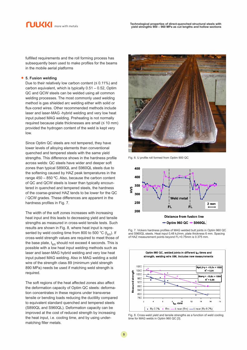
Since Optim QC steels are not tempered, they have lower levels of alloying elements than conventional quenched and tempered steels with the same yield strengths. This difference shows in the hardness profile across welds: QC steels have wider and deeper soft zones than typical S890QL and S960QL steels due to the softening caused by HAZ peak temperatures in the range 450 – 850 ºC. Also, because the carbon content of QC and QCW steels is lower than typically encoun-tered in quenched and tempered steels, the hardness of the coarse-grained HAZ tends to be lower for the QC / QCW grades. These differences are apparent in the hardness profiles in Fig. 7.
The width of the soft zones increases with increasing heat input and this leads to decreasing yield and tensile strengths as measured in cross-weld tensile tests. Such results are shown in Fig. 8, where heat input is repre-sented by weld cooling time from 800 to 500 °C (t8/5). If cross-weld strength values are required to meet those of the base plate, t8/5 should not exceed 4 seconds. This is possible with a low heat input welding methods such as laser and laser-MAG hybrid welding and very low heat input pulsed MAG welding. Also in MAG welding a solid wire of the strength class 89 (minimum yield strength 890 MPa) needs be used if matching weld strength is required.
The soft regions of the heat affected zones also affect the deformation capacity of Optim QC steels: deforma-tion concentrates in these regions under transverse tensile or bending loads reducing the ductility compared to equivalent standard quenched and tempered steels (S890QL and S960QL). Deformation capacity can be improved at the cost of reduced strength by increasing the heat input, i.e. cooling time, and by using under-matching filler metals.
Fig. 6. U profile roll formed from Optim 900 QC
Fig. 7. Vickers hardness profiles of MAG welded butt joints in Optim 960 QC and S960QL steels. Heat input 0,48 kJ/mm, plate thickness 6 mm. Spacing of HAZ measurement points beyond FL+0.75mm is 0.375 mm.
Fig. 8. Cross-weld yield and tensile strengths as a function of weld cooling time for MAG welds in Optim 960 QC [3].
55

Technological properties of direct-quenched structural steels with yield strengths 900 – 960 MPa as cut lengths and hollow sections
The HAZ softening that occurs when t8/5 exceeds 4 seconds does not cause problems, however, when it is taken into account in the design of the structure. Such welds should be located away from the most stressed parts.
Compared to conventional quenched and tempered steels, Optim QC grades are superior with respect to the impact toughness of the fusion line and HAZ due to their lower carbon and alloy contents.
As shown by the examples in Figs. 9 – 10 when t8/5 does not exceed 15 seconds the Charpy V impact toughness of the heat affected zones of Optim QC steels is good, greater than 34 J/cm² at -40 °C, which corresponds to the 27 J for a full size 10 x 10 mm standard test specimen. This is true even for the very short cooling times of laser-MAG hybrid welds, Fig. 6 [4] and pulsed MAG welds, Fig. 8. Increasing arc energy impairs the impact toughness in the fusion line / HAZ, which is typical of all C-Mn steels due to grain growth in the fusion line and coarse-grained HAZ, Fig. 11.
The static strength and fracture characteristics of Optim QC steels are treated further in an accompanying paper in this conference [5].
• High-frequency welding Optim 900 QC high strength steel can be roll formed and longitudinally high-frequency welded to rectangu-lar hollow sections with wall thicknesses of 3 – 6 mm and outer corner radii 2 – 6 times the thickness. The mechanical properties after the forming operation are typically at same level as those of the base material.
Due to its focused heat input, high-frequency welding is a suitable method for Optim 900 QC steel because it enables welded joints to be made with tensile strengths close to those of the base plate. As with the HF welding of all low-alloy steels, there is a narrow ferritic line at the centre of the weld due to local decarburization. During the formation of the weld, the carbon-rich liquid phase in the semi-solid material present at the peak temperature is squeezed into the weld flash that is subsequently removed. Either side of this 50 – 100 µm wide ferritic layer is the coarse-grained zone normally associated with fusion welds, where the temperature exceeds about 1100 ºC. This zone is bounded by areas where the peak temperature reaches about 450 – 850 ºC causing tem-pering and softening of the martensite / bainite micro-structure [6]. The result is a hardness profile across the HF weld like that shown in Fig. 12.
Fig. 9. Charpy V impact toughness of the laser-MAG hybrid welded butt weld in Optim 960 QC. t8/5 ~ 1-2s. Plate thickness 6 mm [4].
Fig. 10. Impact toughness of pulsed MAG welded Optim 960 QC butt weld. t8/5 ~ 2 seconds. Plate thickness 6 mm.
Fig. 11. Charpy V impact toughness at -40 °C across a MAG butt weld in 6 mm thick Optim 900 QC, 6 mm thick. Welded using OK Autrod 13.31.
66

Technological properties of direct-quenched structural steels with yield strengths 900 – 960 MPa as cut lengths and hollow sections
When Charpy impact testing is done with the notch located on the centre-line of the weld, strain is concen-trated in the narrow soft zone on the centre-line with the result that impact toughness is greatly reduced com-pared to other locations, see Fig. 13 [6].
Despite having a high transition temperature in the Charpy V test, the soft ferritic layer does not cause failure in weld ductility tests based on tensile testing, bending, expansion or flattening. In all these cases, failure occurs in the wider soft zones either side of the coarse-grained zone. These zones are characterized by good impact toughness as can be seen from Fig. 13 [6].
The structural significance of the narrow ferritic zone has been investigated using the experimental set-up shown in Fig. 14. In the test assembly, the HF welded joint was loaded in tension in the transverse direction by two plate lugs as shown. The structural hollow section
Fig. 12. Hardness profile across HF weld in 4 mm thick Optim 900 QC. Structural hollow section 100 x 100 mm.
Fig. 13. Charpy V impact transition curves of roll formed 4 mm thick Optim 900 QC and the HF weld at the centre-line and 1.5 mm from centre line. (Charpy specimen size 4 x 10 mm).
Fig 14. Test arrangement for examining the influence of the soft ferritic zone on the centre-line of the HF longitudinal weld. The position of the longitudi-nal HF weld is slightly off-centre as shown in the figure on the left.
was made from Optim 900 QC and had the dimensions 120 x 120 x 6 mm. The plate lugs were 20 mm thick and 200 mm wide and were MAG welded to the structural hollow section with a matching weld metal (Union X96) with a throat thickness of 6 mm. Tensile testing was done at 20, -40 and -60°C. The tests showed that the softened zone at the centre line of HF weld is so narrow that it has no influence on the durability of the welded assembly at any of the test temperatures. Deforma-tion concentrates in the wider softened zones located adjacent to the welded joints of the lug, where peak tem-peratures are in the range 450 – 850 °C.
• 4. Weather resistant ultra-high strength steelIt has been possible to make an ultra-high strength steel with good atmospheric corrosion properties by alloying with suitable amounts of Cr, Ni and Cu in accordance with ASTM G101-04 [7]. The resultant steel, Optim 960 QCW, has the chemical composition and mechanical properties shown in Tables 4 and 5 [8]. Besides be-ing usable in the unpainted condition, the steel shows improved aesthetic performance when painted because under-film corrosion is inhibited by the formation of a stable patina in any damaged areas. The corrosion rate of Optim 960 QCW has been compared to that of COR-TEN A and Optim 900 QC using salt spray and electro-chemical tests in the laboratory, see Table 6. It can be seen that the corrosion properties of the QCW grade are superior to the QC grade and even better than those of COR-TEN A.
• AcknowledgementsThe authors are grateful to Dr. Timo Björk of Lappeen-ranta University of Technology for the testing shown in Fig. 12 and to Mr. Kari Mäntyjärvi and Mrs. Anu Väisän-en of the University of Oulu for the analysis shown in Figs 4 and 5 and Table 3.
77

Technological properties of direct-quenched structural steels with yield strengths 900 – 960 MPa as cut lengths and hollow sections
• Basic chemical composition limits and carbon equivalent values (wt. %) Table 4
Optimgrade
Cmax
Simax
Mnmax
Cu Cr Nimax
Pmax
Smax
Timax
CEVtypical
960 QCW 0.12 0.25 1.20 0.25 – 0.70 0.50 – 1.50 0.50 0.020 0.010 0.07 0.51
Additionally Al, Nb, V, Mo or B are used either singly or in combination. CEV = C+Mn/6+ (Cr+Mo+V)/5+ (Cu+Ni)/15
• Minimum specified tensile and impact properties of Optim 960 QCW Table 5
Rp0.2MPa
RmMPa
A%
Charpy V, longitudinal, -40 °CJ/cm2
960 1000 7 34
• Corrosion rate losses in laboratory testing Table 6
Steel Salt spray for 408 h (mg/cm2)
Electrochemical REP electrolyte (μm/a)
Electrochemical 0.1M NaCl + 0.5M Na2SO4 (μm/a)
Optim 960 QCW 24 33 26COR-TEN A 25 36 47Optim 900 QC 31 37 26
• References1) D. Porter, M. Hemmilä, R. Laitinen And T. Liima-
tainen, Super-High Strength Steels, 1st International Conference, Rome, Italy, 2-4 Nov. 2005.
2) D. Porter, Nordic Welding Conference ‘06. Tampere, Finland, 8-9 Nov. 2006
3) R. Karppi, P. Leiviskä and R. Laiitinen, Develop-ments in MAG-welding for Ultra High Strength Steel; Optim 960 QC, International Symposium “From Welding and Fracture Mechanics to Pipeline Tech-nology” in Honour of Dean Masao Toyoda’s Retire-ment, Osaka University, Japan, June 29, 2008
4) R. Laitinen, M. Lehtinen, A. Fellman And V. Kujan-pää, Influence of Laser and CO2 Laser-MAG Hybrid Welding on the Strength and Toughness of the Weld HAZ of Ultra High Strength Steel Optim 960 QC, Proceedings of 10th NOLAMP conference, Luleå, Sweden, 17-19 August 2005
5) T. Nykänen, T. Björk, P. Nevasmaa, P. Karjalainen-Roikonen, A. Laukkanen, T. Limnell And J. Kuop-pala, Super-High Strength Steels, 2nd International Conference, Peschiera del Garda, Italy, October 17 - 20, 2010 (These proceedings).
6) S. Tihinen, Master’s thesis 2007, Optim 900 QC-teräksen HF-hitsattavuus (Electric Resistance weldability of the Optim 900 QC steel), Materials Engineering Laboratory, University of Oulu (in Finn-ish)
7) ASTM G101-04, Standard Guide for Estimating the Atmospheric Corrosion Resistance of Low-Alloy Steel.
8) M. Arponen and J. Kömi, Ultra-High-Strength Hot-Rolled Structural Steel with Enhanced Inherent Cor-rosion Resistance, Steels in Cars and Trucks (SCT 2008), Wiesbaden, Germany, June 1 - 5, 2008
Copyright © 2010 Rautaruukki Corporation. All rights reserved. Ruukki, Rautaruukki, More with Metals and Ruukki’s product names are trademarks or registered trademarks of Rautaruukki Corporation.
• For further information please contact:
Rautaruukki Corporation, Suolakivenkatu 1, FI-00810 Helsinki, Finland. Tel. +358 20 5911.For further information please contact: [email protected].
88