techno economic evaluation of anchor plates in prestressed
TRANSCRIPT

TECHNO ECONOMIC EVALUATION
OF
ANCHOR PLATES IN PRESTRESSED CONCRETE SLEEPERS
BY
HEINRICH JANSEN VAN VUREN
SHORT DISSERTATION
SUBMITTED IN PARTIAL FULFILLMENT OF THE REQUIREMENT FOR THE DEGREE
MAGISTER INGENERIAE
IN
ENGINEERING MANAGEMENT
IN THE
FACULTY OF ENGINEERING
AT THE
RANDSE AFRIKAANSE UNIVERSITEIT
SUPERVISOR : PROF. L. PRETORIUS
CO-SUPERVISOR : PROF. G. J. VAN DEN BERG
NOVEMBER 1998

ACKNOWLEDGEMENTS
I would like to extend my thanks to the various parties without whose encouragement and
co-operation this thesis would not have reached a successful conclusion.
To Tibor Bodolai who patiently did the drawings needed for the laboratory tests.
To Nico Erasmus for his help during the bending tests at the University of Pretoria
To University of Pretoria and Prof. V. Marshall for their assistance and test report on the
bending tests.
To Chris Malujlo for the clear drawings used in the short dissertation.
To Brian Meynell for his input and drawing work done on the tooling for the
manufacturing process.
To Alfred Tinus who assisted me during the laboratory tests done at Grinaker Duraset
Brakpan.
To Nicholas Papenfus, Con Keyser, Christo van der Merwe, Neels Engelbrecht. and
Hannes Pretorius for the assistance and motivation during the project.
To Piet Bezuidenhout for the help and work done on the testing equipment.
Finally, I would like to extend many thanks to Carol Bell who patiently typed this short
dissertation and wherever necessary, made changes and revisions to the style and
grammar. For all these people I say many thanks.

Opsomming
Die tegniese sowel as die ekonomiese aspekte word in ag geneem met die evaluasie van 'n
nuwe anker plaat. Die oorsprong van die dwarsleers sowel as die oorsprong van die ankerplaat
wat in die "thosti" dwarsleer gebruik word , word breedvoerig verduidelik in die skripsie. Dit
is noodsaaklik dat al die aspekte wat deel uit maak van die produksie van die dwarsledrs in ag
geneem moet word met die evaluasie van die ankerplate.
Daar is basies drie soorte dwarsleers wat gebruik word in die spoorbane van vandal! naamlik:
Flout
Staal
Beton.
Beton dwarsleers was voorgestel om hout te vervang. Die voorafgespande betondwarsleer wat
op die -thosti" produksieproses vervaardie word , word gebuik gedurende die evaluasie. Die
anker plaat wat gebruik word in die produksie van die dwarsleer verseker dat die drukkrag wat
onstaan as gevolg van die voorspanning voldoende tot die omliggende beton verplaas word.
Die ankerplate word met behulp van laboratorium toetse sowel as produksie toetse geevalueer.
Indien die toetse suksesvol is sal 'n ekonomiese evaluasie gedoen word. Die ekonomiese
evaluasie sal die volgende aspekte aanspreek :
Materiaalkoste
Arbeid
Onderhoud
Gereedskapkostes
Die implimentasie van die produk sal volg indien die evaluasie suksesvol is. Die
implimentasie van die produksie sal sekerlik nie sonder enige probleme afloop nie maar elke
poging sal aangewend word om probleme te vermy.

Summary
The technical as well as the economical aspects were taken into account during the evaluation
process of the anchor plates. The origin of the sleepers as well as the origin of the anchor
plates used in the "thosti" production process is briefly explained. It is essential that a better
understanding regarding the manufacturing process is created, for any aspect during the
production could influence the outcome of the evaluation.
Three basic sleepers are used in the modem tracks today namely:
Timber
Steel
Concrete
Concrete sleepers were introduced as a substitute for timber sleepers. Two types of concrete
sleepers are explained namely:
Reinforced twinblock sleeper
Prestressed monoblock sleeper.
The prestressed concrete sleepers are manufactured in the "thosti" process as will be
explained, and a long-line process. The anchor plates used for the evaluation are used in the
"thosti" production process. The anchor plate is used to transfer the compressive stress
induced by the prestressing to the surrounding concrete.
The anchor plates were evaluated by means of laboratory tests as well as production tests.
The economic evaluation was only done after the tests have been done and proven
successfully. During the economic evaluation the following aspects were recognizable:
Material costs
Labour costs
Maintenance costs
Tooling costs
The next step would be to implement the proposal.

CONTENTS
Chapter I Introduction to Anchor Plate Viability Study
1.1 Introduction 1 - 1 1.2 Approach 1 - 1 1.3 Definition of anchor plates I - 1 1.4 Conclusion 1 - 7
Chapter 2 Railway Sleepers
2.1 Introduction "7 Background 23 Summary
Chapter 3 Literature Study
3.1 Introduction 3. 2 Manufacturing of sleepers abroad
7 - 1
2 - 1 -
3 - 1 3 - 1
3. 7 .1 Netherlands production system 3- 1 3.2.2 Twinlock sleeper production in Belgium 3 - 4
3.3 Conclusion 3 - 6
Chapter 4 A South African Production System for the Manufacture of Prestress Concrete Sleepers
4.1 Introduction 4 - 1 4.2 Thosti production system 4 - 1 4.3 Conclusion 4 - 7
Chapter 5 Production System for Anchor Plate Manufacturing
5. Introduction 5 - 1
5.1 Flat anchor plate 5 - 1
5.1.1 Production layout 5 - 1 5.1.2 Problem description 5 - 4 5.1.3 Conclusion of flat anchor plate 5 - 5
5.2 Proposed Solution 5 - 6
5.2.1 Production layout 5 - 6 5.2.2 Tests 5 - 7
12.2.1 Laboratory testing 5 - 8 5.2. 7 .2 Production testing 5-10

51 3 Test results 5 - 11
5 2 3 I Laboratory test results 5.2.3.2 Production tests results 5.2.3.3 Conclusion of laboratory and production tests
5-11 5-17 5-17
5.2.4 Economic evaluation 5 - 17
Chapter 6 Conclusion
6.1 Introduction 6 - 1 6.2 Summary of results 6 - 1
6.2.1 Technical results
6 - I 6.2.2 Economical results
6- 2
6.3 Implementation 6 - 3 6.4 Recommendations 6 - 3
References 7 - 1

List of Figures
Figure 3.1 Prestressing beds with moulds in position 3 -
Figure 3.2 Casting process of sleepers in the Netherlands 3 -
Figure 3.3 Flow diagram of longline production for manufacturing
of sleepers 3 - 3
Figure 3.4 Discharging of concrete into casting machine 3 - 4
Figure 3.5 Trimming and smoothing being done of top concrete
surface of the mould 3 - 5
Figure 3.6 Lifting and turning of mould 3 - 6
Figure 4.1 Flow chart of Thosti production system 4 - 1
Figure 5.1 Typical wire pair 5 -
Figure 5.2 Production layout of wire pairs 5 - 3
Figure 5.3 Proposed channel anchor plate production 5 - 7
Figure 5.4 Proposed testing apparatus 5 - 9
Figure 5.5 Top view of test apparatus 5 - I 1
Figure 5.6 Configuration of dial gauees to measure deflection 5 - 12
Figure 5.7 Indentation caused by the buttonhead in the German
anchor plate at 80 % stress 5 - 14
Figure 5.8 Top view illustration of 300WA channel anchor plate 5 - 15
Figure 5.9 Indent caused by buttonhead on channel anchor plate
at 80 % stress 5 - 15
List of Tables
Table 5.1
Stress loss due to bending of the anchor plate 5 - 13
Table 5.2
Stress loss in system 5 - 16

CHAPTER I
Introduction to anchor plate viability study
1.1 Introduction
Concrete sleepers, as we know them today have evolved significantly over the last
century. They were introduced as a substitute for timber sleepers. The Railway
Association became the main customer and their needs had to be met and still must
be met today. The trains might be faster and the loads might be heavier, but the
sleepers must still be adequate to withstand the forces and be reliable for ensuring
the safety of every person travelling.
It is therefore of great importance to manufacture the sleepers cheaply and
economically cost effective.
1.2 Approach
To determine whether a sleeper can be made cost effectively, it is of great
importance that all the aspects for manufacturing, supplying etc., of the sleeper
must be understood. The aim is to give the reader, a good understanding about the
manufacturing of concrete sleepers and other aspects involved during the
production as well as the research methodology used [Reference 8]. In chapter two
railway in general will be discussed whereas in chapter three and four the
manufacturing process of concrete sleepers.
1. 3 Definition of anchor plates
The anchor plates are used for anchorage of the prestressing wire in the concrete
sleeper. In the Prestressed Concrete Designer's handbook, [Reference 1], four
anchoring systems for prestressing are explained.
The anchoring system that will be used for this investigation is a combination
between the Mcalloy system, the BBRV system and the Prescon system. An

I - 2
anchor plate is used to transfer the prestressing force to the concrete and is
anchored with an anchor bolt and nut. [Reference 11. The wires are anchored
through the plate by means of a buttonhead, represented by BBRV and Prescon.
The anchor plate that is used for positive anchorage of the stressing wire in the
sleeper is of vital importance. The wire used in the sleeper is not indented and
therefore cannot transfer the compressive force to the concrete very efficiently in
bond. The compressive force is therefore transferred by means of the anchor plate.
The manufacturing process for the anchor plates can be an expensive and time-
consuming operation. For this reason it was decided that the manufacturing
process and the anchor plate would be investigated for the economical viability
study.
1.d Conclusion
Now that the investigated object is identified, as well as the use of the anchor plate,
a more in-depth discussion of the sleeper. manufacturing process, as well as the
investigation process can be done.

CHAPTER 2
Railway Sleepers
2.1 Introduction
The aim of this chapter is to introduce the reader, to concrete sleepers and why they
are used in railway lines today. In this chapter the design of sleepers will not be
explained. for this is confidential information held by the supplier of the concrete
sleepers. The components involved with the sleeper however will be explained.
2.2 Background
The first design in the United States for concrete sleepers was done in 1884 and the
Reading Company in Germantown. Pennsylvania installed the sleepers in 1893.
[Reference 2].
In 1902 the first reinforced concrete sleeper in Hungary was designed. [Reference
3] It was at the end of the forties that railway companies required crack-free
sleepers. Various types of prestressed concrete sleepers evolved and changes and
tests are still being done to accommodate the new technology trains with high
speeds and axle loads.
It was only in 1957 that work was done on prestress concrete sleepers in the United
States of America [Reference 2]. The first concrete sleepers were installed in 1960
and by 1967. 74 000 sleepers were installed in North America.
Various sleepers were manufactured in the world. These sleepers contained types
like [Reference 3]:
Twinblock sleepers
Monoblock reinforced concrete sleepers
Monoblock prestress concrete sleepers

2. 2
Various production systems arose for manufacturing the concrete sleeper as
quickly and as economically as possible.
The sleeper that will be used in this investigation is called a "Thosti" sleeper. This
name originated from the manufacturing process used for these sleepers.
The "Thosti" sleeper is a prestressed monoblock sleeper. During the
manufacturing the Mealloy and BBRV systems as described in Chapter 1 are used
for the prestressing of the sleeper. The "Thosti" production system will briefly be
explained in further chapters.
73 Summary
It is clear that the use of concrete sleepers developed extensively during the 20 th
Century. The prestressed concrete sleepers are fairly new if one considers that the
development of prestressed concrete sleepers in the United States of America only
commenced in 1957. This was done to eliminate cracks in sleepers during working
conditions. The next chapter will give the reader, a brief introduction on the
manufacturing processes abroad for manufacturing prestressed as well as
reinforced concrete sleepers.

CHAPTER 3
Literature Study
3.1 Introduction
Manufacturing processes that could produce high volumes of concrete sleepers at
the most economical costs were needed due to the fast growth of rail transport and
the need to run higher speeds and loads on the tracks.
Various parameters were used for investigating the most economical method of
sleeper manufacturing. These parameters included the production capacity,
location circumstances and the degree of automation. All these parameters were
influenced by the complexity of design, handling of the product, size and weight of
the product. [Reference 4].
32 Manufacturing of sleepers abroad
3.2.1 Netherlands production system
The system used in the Netherlands [Reference 5] is called a longline system, and
will be explained briefly in the next few paragraphs.
The plant consists of a prestressing bed, 90 m long, with thirty-five 4 compartment
moulds. This would mean that 140 sleepers can be produced in one line. The
line with the moulds placed in position can be seen in figure 3.1.

3 - 2
Figure 3.1 Prestressing beds with moulds in position.
The prestressing wires are placed through the active and passive ends of the
prestressing beds. The active end is the point where the wires will be stressed and
the passive end is the fixed end of the line where no movement of the wire will
take place. The sleepers are cast as shown in Figure 3.2.
Figure 3.2
Casting process of sleepers in the Netherlands.

'Wire Cutting 1-4
Prepping ---IClean ng of mould
—10ding
—1Placing reinforcing and in
—4Stressing
Casting
Cast
3 - 3
The concrete is cured using steam injection that is situated beneath the moulds.
The sleepers are suspended at the same height by means of transport carriages,
whereafter the mould is lowered. The stress is released and the sleepers are
forwarded to the cutting station. whereafter they are turned 180 ° . '
Figure 3.3 illustrates a flow diagram for the longline production system.
The wire is cut in lengths of 100 m each. At the same time the moulds are cleaned
from concrete spillage and dust. The release oil is sprayed to the inside of the
mould to act as a release agent when demoulding. The fastening systems,
reinforcing wire and other inserts such as ferrules are placed in the moulds.
The casting process is done by placing the concrete with an overhead concrete skip
and vibrating the concrete mechanically.
Curing blankets then insulate the moulds. After the curing process the moulds are
lowered from the product. The reinforcing between the products are cut and
transported to the turning station, where they are turned 180 °. The products are
transported to the stockyard where they are despatched to various sites.
ia•
Figure 3.3
Flow diagram of longline production for manufacturing of sleepers.

3 - 4
3.2.2 Twinblock sleeper production in Belgium 'Reference 41
The production system uses a pallet tilt-up forming machine. The machine is
connected to an automatically controlled pallet circulation system and take-off
arrangement.
The concrete is supplied to a conveyor which in turn delivers the concrete into a
transfer bucket. The bucket moves via an overhead rail to the casting area
whereafter the concrete is discharged in the casting machine. The casting process
can be seen in Figure 3.4.
Figure 14 Discharging of concrete into casting machine.
Each mould is prepped before casting. The prepping process will involve the
cleaning, oiling and placing of the reinforcing in the mould.
3 - 5
The casting machine is divided into simple stationary parts which comprise of a
metering system as well as a concrete distributor. When the reinforcing is placed
in the mould the casting can be done. The concrete is compacted using two
vibrator motors. A hydraulic charging truck fills the mould whereafter the
trimming and smoothing beam finishes the casting stage. [Figure 3.5]
Figure 3.5
Trimming and smoothing being done of top concrete surface of
the mould
The mould is lifted, turned and demoulded onto a pallet. Figure 3.6 illustrates the
lifting and turning process.

3 - 6
Figure 3.6 Lifting and turning of mould.
The sleepers are transported by means of a conveyor whereafter curine; cleaning
and shipping will take place.
3.3 Conclusion
Two different production systems as well as two different sleepers are recognisable
in this chapter. The monoblock prestressed concrete sleeper is produced on a
longline system where curing is done before destressing and demoulding whereas
the twinblock reinforced concrete sleeper is manufactured on a pallet tilt-up
forming machine, where the demoulding is done before curing.
Prestressed concrete needs a certain release strength to be able to transfer the
prestressed force to the sleeper whereas the reinforcing sleeper does not need as
high strengths, such as 30 - 35 ;VIPs cube strength, for demoulding. This will be
explained in greater detail in Chapter 5.

5 ( as cu 'ng )
Promos
5 moulds
transport
CHAPTER 4
A South African Production System for the Manufacture of Prestressed Concrete Sleepers
41 Introduction
The sleepers manufactured in South Africa are mainly monoblock prestressed
concrete sleepers. Two systems are used for the manufacturing of prestressed
concrete sleepers namely:
Longline
Thosti
The longline system will not be explained further in this chapter for the system is
based on the longline system used in The Netherlands as explained in Chapter 3.
The "Thosti" production system will be explained briefly in this chapter but for
confidentiality reasons the system is explained in greater detail in the Grinaker
Duraset Report. [Reference 6]
4.2 Thosti production system
Figure 4.1 below illustrates the various staues in the production system.
FLOW CHART
Go-tensioning)
transalearl to ( aptinkhhq rallb over
erationa of mould]
1
011,7:ana of 7-0-C Inseantrtlanoragoal )--P-Cri netnIng pranrinarge,of 'nfarcernents
I
/precoraticn 7 / meta
a raInfore manta concrete
Figure 4.1 Flow chart of Thosti production system

4- 2
Each stage will be explained briefly
Stage I. Cleaning and oiling of the mould. The oil is used as a release agent for demoulding.
Stage 2. The fastenings as well as the reinforcing wire is placed into the mould. The bolts are tightened for straightening the wirepair before stressing.
Stage 3. The reinforcing is stressed and anchored at the correct stressing force.
Stage 4. The concrete is fed to the mould by means of an overhead discharge bucket. The mould is placed on a vibrating table during the casting process.
Stage 5. The moulds are transported to the curing chambers after the casting process is complete.
Stage 6. Curing takes place until the required release cube strength has been reached. The sleepers are demoulded by turning the mould 180 ° .
Stage 7. The bolts are detensioned when the required release cube strength has been reached.
Stage 8. The empty moulds are turned over for cleaning and oiling.
Stage 9. The sleepers are transported to the finishing stage where the corking of the bolt holes take place.
Stage 10. The finished sleepers are transported to the stockyard whereafter they are dispatched to the client.
4.3 Conclusion
This process may seem very simple but a lot of process planning, time manaaement and sophisticated equipment goes into this process. The anchor plates that are explained in the next chapter are only one small part of this process.

CHAPTER 5
Production System for Anchor Plate Manufacturing
5. Introduction
During this chapter the manufacturing process of the flat anchor plate, that is currently
used, is explained. The investigation of the proposed anchor plate as well as the
shortcomings are explained in this chapter.
5.1 Flat anchor plate
In the current production of Thosti concrete sleepers a flat anchor plate is used. The
anchor plate is manufactured from a flat strip of steel with various dimensions. The
second paragraph of this chapter will illustrate the production of the flat anchor plate.
5.1.1 Production layout
The production of the flat anchor plate is a very simple process. Although it is simple it
is also a labour intensive process. The manufacturing of the anchor plate is not the only
process for the manufacturing of wire pairs. The wire is of no use without the anchor
plate and the anchor plate of no use without the wire. The total wire pair consists of the
following :
2 lengths of wire
2 anchor plates
The anchor plate is secured with a buttonhead on each end of the wire. The buttonhead is
a ball-shaped head formed on the end of the wire. The buttonheading system is adapted
from the BBRV or Prescon system as was described before. The buttonheading method
is a simple process but uses fairly sophisticated machines. The process involves two
stages namely;
Clamping of wire
Button forming

5 - 2
The button former is used to press the wire tip, forming a ball form at the tip. This
process is done just after the wire clamping stage. The clamping stage is used to prevent
any slippage or movement of wire when the tip is formed.
Figure 5.1 illustrates a typical wire pair.
PRESTRESSING WIRE
ANCHOR PLATE
BUTTONHEAD
Figure 5.1 Typical wire pair
Now that some of the processes are understood, the production layout for the
manufacturing of a complete wire pair can be explained. Figure 5.2 illustrates using a
block diagram, what processes are involved in the production of a wire pair.

Assembly
of ■ts*. wirepair
2 Men
Buttonheading 2 Men
Stacking
1 Man ∎►
Cropping of wire I Man
5 - 3
Punching of anchor plate 1 Man
Drilling of anchor plate
1 Man
Figure 5.2 Production layout of wire pairs
Each of these processes will be explained briefly:
During the punching stage for the anchor plate the flat bar is fed into a die-set
where the plate is cropped to the required length and a hole punched in the centre of the
plate which will accommodate the stressing and anchor bolt.
The cropped plate is taken to the drilling process where two small holes are
drilled for locating the wire.
Each of the processes needs at least one worker. The drilling process is a repetitive
process.
The cropping of the wire is done during the same time as the anchor plate
production. The wire is cut to the required length during the cropping stage.
The cut wires and the complete anchor plates are assembled in the assembly
stage. Two workers are required if a production rate of 4000 wirepairs/day is to be
achieved.

5 - 4
e) The wire is buttonheaded at each end finishing the wire pair production cycle.
The wire pairs are stacked in bundle fonn in the stockyard whereafter they are
sent to various sleeper production plants.
Due to various problems that are explained in the next section it was decided that a new
anchor plate should be developed.
5.1.2 Problem description
Various problems occurred during the production of the anchor. plates. These problems
included aspects like:
Maintenance
Structural integrity
Labour
a) Maintenance
Because no preventive maintenance plan existed, it caused excessive downtime when
maintenance needed to be done. The drilling operation was a very costly operation due to
maintenance. Seals had to be replaced from time-to-time causing unacceptable downtime
rates and high productivity losses. The press used for punching the anchor plates had a
very low downtime rate due to the low maintenance required during production.
It is however essential to determine what the requirements for maintenance should be
during the running operation of the press. Troubleshooting might be done but no formal
procedure as described in Reference 7, page 441 — 451 exists. The maintenance analysis
data cover basically two aspects:
all significant repairable items as well as,
all requirements for maintenance.
This problem needs to be addressed when a new system of manufacturing is
implemented. If a new system is not implemented it is essential that data should be

5 - 5
collected and in turn, be used for setting up a detailed maintenance plan that would
address aspects like downtime. NWT (mean corrective maintenance time), NITTR (mean
time to repair) etc.
Structural integrity
The structural strength of the flat anchor plate was too low to resist the bending forces
imposed on the plate. These results were gathered from deflection and load-tests
performed in Phase I of the project and thiS report can be seen in Appendix 2 of
Reference 6. The results will be explained in greater detail in the next chapter. The
imposed forces caused the plate to deflect in such a way that there was reason to believe
that stress-loss in the prestressing occurred during the bending of the anchor plate. The
stress-loss is the reduction in stress or force if a constant load is applied over a finite time
period. This time period could be minutes, hours, weeks and even years.
Labour
Using labour is no longer a very cost effective method of manufacturing. It is also
important that labour should be trained to fulfil a higher skilled operation that could in
turn, assist with gathering new ideas or systems. It could generate new products that
could then produce work for other labour whereafter they can also be trained and create
other opportunities. This could be a huge chain reaction that would benefit both parties,
namely the employer and employee.
A labour saving can have a huge benefit and this aspect was used as one of the aspects in
the economic evaluation and will be explained in Section 5.2.
5.1.3 Conclusion of flat anchor plate
In the discussion of the above section it was aimed to give the reader, a better
understanding of what is involved in the production of the flat anchor plates, and also
what the problems were which indicated that a new anchor plate with maybe a new
production system. should be investigated. The problems such as labour, structural
integrity and maintenance might not be the only problems but they were the main driving
factors for this evaluation. It is rightfully so that economics play a big role in the

5 - 6
evaluation process, but the economic evaluation cannot be used as a measuring tool when
the current product is structurally inferior. Now that these aspects are better understood,
one can continue to propose solutions and evaluation.
5.2 Proposed solution
It was felt that a more cost effective solution had to be found for the manufacturing of
anchor plates. It was decided that an external search will first be conducted to determine
if and what anchor plates are used in similar production systems throughout the world.
The purpose of this section is to give the reader, an overview of evaluations and tests
performed to eliminate as many variables as possible.
5.2.1 Production layout
One critical aspect in the production is to save labour and time. This should in turn
increase productivity. A search was conducted and it was found that various anchor
plates are used in Europe for the manufacturing of concrete sleepers. It was decided that
the evaluation of which anchor plate to use will be done using the following criteria:
Increase productivity
Reduce labour
Reduce maintenance
Cost effective
Structurally correct
Based on the above criteria it was decided that a channel shape anchor plate would be
investigated. It was realised that no drilling operation is involved in the anchor plate
production when a channel anchor plate is manufactured for the holes could be punched.
This was seen as a great opportunity to save labour and in turn increase productivity. The
press operation was found to be a lower maintenance function as the drilling machine.
This would in turn reduce maintenance and maintenance costs.
A proposed production layout for the manufacturing of 4000 wirepairs/day can be seen in
Figure 5.3. The proposed production layout would save on labour due to the fact that no
drilling operation is required as for the case in Figure 5.2. The proposed anchor plate can

Punching of anchor plate Man
Assembly of
wirepair 2 Men
Buttonheading 2 Men
Stacking I Man
5 - 7
be produced in one press operation, and it is for this reason that the worker used for the
drilling of the flat anchor plate can be used in another operation.
Cropping of wire 1 Man
Figure 5.3 Proposed channel anchor plate production
5.2.2 Tests and results
The evaluation process for selecting the correct anchor plate is a long process for
technical tests have to be performed to determine if the structural integrity of the plate is
efficient. Only then can an economic evaluation be done.
The first aspect that had to be clarified is what steel should be used. It was decided to use
the chemical analysis, done on the German plate that was received and compare it with
the proposed 300WA flatbar.
The chemical analysis has shown that the quantity of each chemical element in the
German plate complied with the 300WA specification. There were however elements
such as:
Molybdenum
Nickel
Copper

5 - 8
Aluminium
Vanadium
that were slightly higher than the 300 WA specification [Reference 6]. The chemical
composition of the German anchor plate relative to the 300WA specification can be seen
in Appendix 2.
It was therefore decided that 300WA will be used during the two proposed test
procedures namely;
laboratory testing
production testing
5.2.2.1
Laboratory testing
It is very important that the shortcomings that occurred during the tests conducted in
previous evaluations would be addressed and corrected.
These shortcomings included the following:
I. High relaxation losses caused by the length of wire used in system. The relaxation
loss is the reduction in stress or force in the wire when kept under load.
2. Temperature changes during each test.
Possible stress losses due to stressing and anchor bolts used in the system.
It was therefore important that a proposal should be done to eliminate these variables.
Design proposal for testing
I The relaxation of the wire should be tested to see what effect the relaxation of the
wire will have on the stress-loss in the system. If the relaxation of the wire is known
then this value can be subtracted from the total stress loss in the system where the
anchor plates are being used.
2. The method of stressing with anchor bolts must be taken out of the system for the
reason that the thread of the bolts can cause a stress loss in the system. This stress

5 - 9
loss cannot always be ignored and therefore it is better to take the bolts out of the
system when the anchor plate must be isolated or to increase the thread so much that
no slip or stress loss could take place.
The initial stress and the temperature of the working environment must be kept
constant throughout the total duration of the test.
Figure 5.4 shows a proposal of how the anchor plates could be tested to minimise the
variables in the system.
O
0 Figure 5.4
Proposed testing apparatus
The loadcell is used to measure the applied load on the wirepair.
The test frame is used to locate or situate all the equipment and the wirepair. It is
designed to resist the maximum applied force that would act on it if the wirepair
is under load.
The anchor plate under investigation.
The stressing plate is used to anchor the wirepair. There are no anchor plates
situated in the plate. The stressing plate is placed in the stressing box whereafter
the stressing operation can be done.
The stressing box is pulled using a stressing bolt and shaft. It slides on plate
during the jacking operation.

5-10
The jack is a hollow-core jack. The stressing bolt is placed through the jack and
located and locked with a nut.
The anchor bolts are used to lock the stressing box in position when the correct
load on the wirepair is applied.
The stressing shaft or bolt is used to connect the jack and stressing box. The shaft
is the link for the stressing operation between the jack and stressing box.
The laboratory test is conducted on the following basis: -
Manufacture nine current 300WA flat anchor plate samples.
Do comparison tests between the 300WA and German plate using the criteria and
apparatus in the design proposal for testing.
The comparison tests are done at 70%, 75% and 80% of 1700 MPa UTS. The UTS is the
ultimate tensile strength of the wire. Three plates of each type are tested at each stress
percentage.
5.2.2.2 Production testing
Sleepers should also be tested to evaluate the effects of the different anchor plates in the
sleepers. Therefore twelve P2 sleepers with the flat anchor plates that are currently used,
and 12 P2 sleepers with the anchor plates that are used in Germany were manufactured.
Two moulds were cast with one batch of concrete so that the concrete strength in the two
moulds is the same. Each of the two moulds were cast with different anchor plates. The
one mould was cast with the normal flat anchor plate and the other was cast with the
German type anchor plate. Six concrete batches were prepared for the total amount of
sleepers. Every two moulds had the same concrete strength but different anchor plates so
that the concrete strength as a variable can be eliminated for the purpose of the
comparison testing between the two types of anchor plates. Equivalent moulds and the
same stressing equipment should be used. Bending tests were performed after 28 days to
determine if there is any difference in the bending ability of the sleeper.
5 - I
5.2.3 Test results
The laboratory testing that was described in the previous section was done using the
current 300WA flatbar and the Gennan plate. Although the chemical analysis was done
and concluded that the 300 WA plate compared very well against the German plate, it was
still decided that 18 samples using 300 WA plate would be manufactured to the
dimensions of the German sample. The test results will be explained in two sections :
Laboratory tests
Production tests
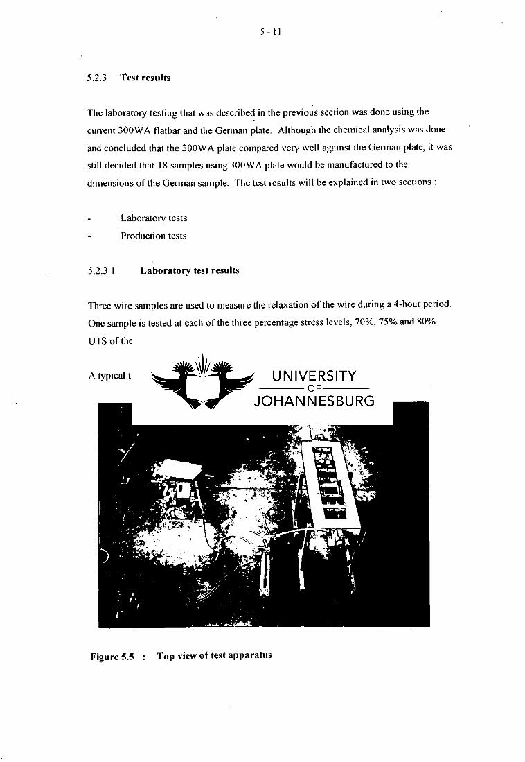
5.2.3.1 Laboratory test results
Three wire samples are used to measure the relaxation of the wire during a 4-hour period.
One sample is tested at each of the three percentage stress levels, 70%, 75% and 80%
UTS of the wire, respectively.
A typical test set-up can be seen in Figure 5.5 and 5.6.
Figure 5.5 : Top view of test apparatus

5-12
Figure 5.6
Configuration of dial gauges to measure deflection.
The stress-loss in the system would include the relaxation of the wire as well as the
stressloss caused by the continuous deflection of the anchor plate. The relaxation of the
wire is subtracted from the system stress loss. These results can be seen in Table 5.1.

5-13
Table 5.1 Stress loss due to bending of the anchor plate
UTS of wire [ MPa = 1700
Area of wire [ mm A 2 1. 28.274
Typo of plate : ... 300 WA' 1 1: .-.... . .. - German Plate
Percentage stress of UTSx! 70 75 80 70 75 80 ..,,...-.:
Load InNj ::,L ... 6729 72.10 " 76.91 ' 6729 ' 72.10 76.91
Test number H:•': 1 2 3 4 I 5 6 7 ' 10 11 12 13 14 ' 15 16 17 18
DdratiotratteOt: The measurements below are given in (kg kg ./
0 min -1 -1 -1 0 0 0 -3 -3 -3 -1 0 0 0 -3 -3 -3
15 min 16 59 -2 31 4 42 15 75 29 -1 11 -12 -16 -6 18 -3 40
30 min 14 64 -4 32 5 60 14 91 31 3 -5 17 -15 -21 -9 27 -12 48
45 min 12 63 -9 34 5 73 13 95 27 6 -10 20 -17 -23 -14 25 -15 49
60 min, 1 hour 15 72 38 9 84 10 100 28 8 -9 25 -15 -21 -12 25 -20 55
75 min 16 73 -3 43 11 88 10 100 28 13 -11 27 -16 -20 -16 26 -24 57
90 min 16 75 -6 43 13 94 5 106 28 14 -13 35 -13 -20 -18 26 -24 59
105 min 17 . 76 -8 46 11 96 3 104 26 15 -15 35 -16 -23 -22 26 -27 61
120 min, 2 hours 16 78 -9 47 15 100 7 109 30 18 -16 35 -14 -20 -21 27 -26 65
135 min 19 80 -9 50 18 102 8 111 31 21 -15 37 -14 -19 -22 25 -26 69
150 min 19 81 -10 55 23 105 10 113 32 22 -17 36 -12 -19 -21 26 -25 70
165 min 19 80 -14 54 22 105 12 113 36 24 -18 37 -12 -20 -21 26 -24 72
180 min, 3 hours 21 83 -17 59 26 104 14 114 37 27 -18 37 -10 -19 -20 25 -23 73
195 min 22 86 -20 58 26 99 16 113 40 30 -18 37 -13 -20 -22 24 -23 73
210 min 21 83 -25 62 29 98 18 113 42 30 -19 36 -13 -17 -19 22 -21 74
225 min 24 85 -27 64 33 96 19 114 42 34 -18 36 -15 -19 22 -17 75
240 min, 4 hours 27 85 -30 67 35 94 22 114 50 41 -17 36 0 -13 -15 22 -13 75
It can be seen from Table 5.1 that a negative stress loss, or stress gain occurred in some of
the tests. This would mean that there would be a gain in stress. A relaxation test was
done using wire samples from the same batch as the sample used for the tests in Table
5.1. The relaxation test only measured the stress loss which occurred in the wire alone,
no anchor plate was present during this test. If a stress gain as in Table 5.1 occur, it

5-14
would mean that the total system, anchor plate and wire, has less stress loss than the wire
alone. This however is not possible. Although the same wire from the same roll was
used, there were still differences. The continuous deflection, as well as the initial
deflection, of the anchor plate was also determined [Reference 6I.
The stress-loss that did occur however, without the plate deflecting continuously could
have been due to:
Relaxation of wire
Indentation caused by the buttonhead. This is illustrated in Figure 5.7.
Figure 5.7
Indentation caused by the buttonhead in the German anchor
plate at 80% stress.
It was decided that the stress loss in the system would be used as a basis for evaluation
and not the stress-loss due to the continuous deflection of the anchor plate. The newly
formed anchor plate is shown in Figure 5.8 and 5.9.

Figure 5.8 Top view illustration of 300WA channel anchor plate.
1 11 \ el.% 1I. ‘C III \ 1,11 3110 WA. 611
70 IL • 1 Itl'.••
1 11 \ \ \ 111 111 P1 1 1 I_
ki III \ 1 ■ \ nun
75 • 1 111 ••
11 \ \VI 1 ‘`,. 111 11 VI \11
• 1 lib Wu V% now.
SR". • 1 111 ••
5-15
N1.1.1 9,4 111 111 PLA 1 1.
Figure 5.9 Indent caused by buttonhead on channel anchor plate at 80%
stress.

5- 16
Table 5.2 indicates the stress-loss in the system for the newly formed plate with 300WA
plate (channel system).
Table 5.2 Stress loss in system
UTS of wire MPa -v. 1700
Area of wire aim 2 I. 28.274
SifiEgij'RIO WA ol;aene DieW;;J>lete '.
pe'egerlYieei;e1;:isi UTS: 70 75 BO , 70 75 BO 70 75
&odd ficni-FE:Hir::: C,C:: - 137-3 72.1 78.9 , 87.3 72.1 76.9 67.3 721
ighi4'Aiih. 1 6860 7350 7840 6880 7350 7840 6860 7350
1 2 3 4 5 6 7 a
Duration of list , - ,e,:/. tt: The measurements below Is given in ( kg 3
0 min 6860 7350 7840 6860 7350 7840 6860 7350
15 min 6841 7322 7809 6860 7329 7822 6848 7325
30 min 6835 7310 7797 6860 7324 7813 6842 7320
45 min 6830 7305 7789 6856 7319 7808 6838 7314
60 min, 1 hour 6827 7301 7783 6852 7317 7802 6836 7311
75 min 6823 7301 7776 6846 7314 7797 6835 7307
90 min 6817 7295 7772 6843 7312 7794 6831 7303
105 min 6813 7288 7768 6840 7310 7792 6831 7299
120 min. 2 hours 6809 7289 7763 6839 7308 7790 6831 7296
135 min 6806 7286 7759 6839 7307 7783 6830 7294
150 min 6803 7285 7756 6839 7305 7781 6827 - 7292
165 min 6802 7284 7751 6837 7302 7778 6825 7291
180 min, 3 hours 6798 7284 7748 6834 7301 7778 6824 7289
195 min 6795 7280 7745 6832 7301 7774 6824 7287
210 min 6795 7278 7743 6832 7300 7772 6819 7285
225 min 6797 7282 7741 6829 7296 7772 6821 7285
240 min. 4 hours 6795 7282 7740 6829 7294 7770 6820 7284
Stressloss [ kg ] : 65 68 100 31 56 70 40 66
% Stressloss : 0.95 0.93 1.28 0.45 0.76 0.89 0.58 0.90
In Reference 6 a detail discussion is given on the results for the investigation of the flat.
German and channel anchor plate. The stress loss for the flat, German and channel
anchor plate at 75 % stress were 2,93 %, 1,91 % and 0,86 % respectively for the total

5-17
system. It can now be concluded that the German and channel anchor plate had less
stress loss than the flat anchor plate [Reference 6].
5.2.3.2 Production test results
Twenty-four sleepers were cast, twelve of which consisted of the German anchor plate
and twelve the flat anchor plate. These sleepers were tested at the University of Pretoria
and the results can be seen in Reference 6.
No significant difference in the bending resistance was noticeable between the sleepers
manufactured with the German anchor plate and those with the flat anchor plate.
5.2.3.3. Conclusion of laboratory and production test
To finalise the results it was decided that a second test should be done. Four sleepers
were cast, two of which consist of the 300WA flat plate and two with the new channel
plate [Reference 6].
There was no signification difference in the strength of the sleeper during the bending
tests, but the manufacturing process for the channel anchor plate is simpler than the
current flat anchor plate production.
It was therefore decided to continue with the economic evaluation of the anchor plates
using the channel plate made from 300WA flatbar.
5.2.4 Economic evaluation
The economic evaluation was based on the standard of a wirepair. It was decided that
two options must be investigated. •
Importing
Local manufacturing
Quotations were submitted for the importing of anchor plates from Germany. The costs
of importing anchor plates were not economically feasible and this option was rejected.
The cost for manufacturing the anchor plate in South Africa was investigated.

5-18
The cost of a wirepair would include:
all material costs
write-off costs of tooling, parts and punches
labour and supervision
The material cost of a wirepair would include the prestressing wire and anchor plate
material.
The write-off for tooling, parts and punches, is based on two factors:
cost of replacing tool, inserts and parts
time before replacement
The time to replace could be determined accurately if a good maintenance plan exists.
This however is not the case and estimations based on the experience of the tooling
experts were used for the calculations of the write-off costs.
The labour cost as well as the supervision includes a mark-up percentage to compensate
for increases and overtime.
A more detailed breakdown of the evaluation can be found in Appendix 8 of Reference 6.
For this report a detailed discussion can be seen in Appendix 1.
It was found that a 2.25% saving can be achieved. This however could increase to
approximately 3,15% if a higher productivity rate with less labour is reached.

CHAPTER 6
CONCLUSION
6.1 Introduction
The manufacturing of prestressed concrete sleepers may seem simple, but detailed
planning and problem solutions are needed during production Two production systems
for the manufacturing of concrete sleepers were discussed namely;
Longline
Thosti
The Longline production is used when huge volumes are required. The Longline system
is not economical when small quantities and big variations need to be manufactured. The
Thosti system on the other hand is much more adaptable to small quantities as well as for
big variations of concrete sleepers.
Although the anchor plates are such a small element in the total production system. they
can cause huge problems when not used correctly or if they fail. This could easily result
in production losses. The anchor plates were therefore tested in such a way that the
variables, which occurred during the previous evaluations, could be eliminated.
6./ Summary of results
6.2.1. Technical results
During an evaluation conducted by Holtz [Reference 61, it was found that the 300 WA flat
anchor plate deflected more than the "Castro bar" used at that time. "Castro bar" was a
32 x 9,54 mm flatbar with a yield strength of 525 MPa. The "Castro bar" was used for
the manufacturing of flat anchor plates at that time. The deflection of the anchor plate
however caused great concerns, namely;
the plate might shear under load

6- 2
the reduction of steel area of the anchor plate's front face might reduce the degree
of prestress reached under the railseat
the yield in the anchor plate due to stressing might cause further reduction in
prestress.
The concerns were proven unnecessary for the plates did not fail during testing. It was
found that a 6,3% saving in material costs alone could be achieved. Shortcomings
however did occur during T.Holtz's evaluation and Phase I [Reference 6]. It was
therefore necessary that Phase 2 [Reference 6] must be aimed at eliminating as many
variables as possible.
During this investigation it was found that the German plate as well as the 300WA
channel plate induced less stress-loss than the flat anchor plate. The anchor plates did not
deflect continuously, and could not have induced any stress loss due to bending. The
stress loss however could occur due to the following:
Higher relaxation of wire
Indentation caused by buttonhead
It was found that no significant difference in bending moment resistance occurred
between the sleepers using the channel or German anchor plate and those using the flat
anchor plates .
6.2.2 Economical results
In the evaluation by Holtz. the material cost was the only saving considered [Reference
6]. In Holtz's report no consideration was given to labour savings, maintenance and
tools. The material cost for the anchor plate production reduced by 6,3% when a 300WA
plate was used instead of the "Castro bar"[Reference 6]
Only during this investigation the economical and technical considerations were taken
into account during the anchor plate production Labour, tooling life, time and material
costs were considered during the evaluation. It was found that a saving of between I.S%
and 2.7% could be achieved if a 300WA channel plate is used instead of the 300 WA flat
anchor plate.

6 - 3
6.3 Implementation of channel anchor plate production process
A progressive tool for the manufacturing of the channel was made and tested to determine
whether the tool would produce the channel anchor plate within specification. A
progressive tool is a single tool which has multiple stages. Each stage will do a certain
operation to ultimately, when the plate has been through various stages, would be
completed within specification.
The tests however did not prove to be very successful for cracks occurred on the outside
of the bend of the anchor plate. Various steel suppliers were contacted for advice on
solving the problem. This investigation is an ongoing process and can be considered for
future research.
6.4 Recommendations
It must be noted that stress-loss could occur during wire relaxation. bending of anchor
plate, as well as the indentation of the buttonhead into the anchor plate.
With these considerations in mind. it would be recommended that a new test procedure or
test equipment be used, which would enable one to test the relaxation, bending and
indentation more accurately.
Other considerations would be:
Conducting a good maintenance plan by gathering data on the maintenance done
in production.
Evaluate other production systems.
Update standard when a detailed maintenance plan exists and write-off costs can
be predicted more accurately.
To conclude, it can be said that the evaluation for the manufacturing and use of the
300WA channel anchor plate proved positive, but consideration must be given to the
indentation and tooling for manufacture.

References
B.K Bardhan-Roy P.W Abeles ; Types of prestressing steel :Prestress concrete designers
handbook : Third edition page 72
Amir N. Hanna ; A century of ties • Concrete International ; August 1990
Janos Beluzsar , Gyula Fogarasi ; Manufacturing of railway sleepers and special sleepers
for switches and crossings in Hungary FIP '90 XI congress : Volume II 4 - 9 June 1990
Siegfried Schwarz : Two plants for the production of concrete sleepers and cable channel
elements in Belgium Betonwerk Fertigteil Technik • Issue 8 ; 1993
Siegfried Schwarz ; Modern production plant for prestressed concrete sleepers in the
Netherlands ; Concrete precasting plant and technology ; Issue 9 • 1991
H. Jansen van Vuren Techno economic evaluation of anchor plates in prestress concrete
sleepers ; Grinaker Duraset Report ; Grinaker Duraset Brakpan Branch ; November 1998
Benjamin S. Blanchard Logistics Engineering and Management Fourth Edition ;
Prentice Hall Englewood Cliffs ; 1992
8) Donald R. Cooper , C. William Emory ; Business research methods ; Fifth Edition ; Irwin
1995

Appendix 1: Detailed discussion on wirepair cost
evaluation
Note: Only the principles and aspects that were used for the evaluation are explained. This report does not show any values or final calculation.

Price . dim Cost_of material .=Ze _p Anchorlatematerial
1000
2/12/99 APPENDIX 1 Anchor plate project The cost saving between the German anchor plate and the Flat anchor plate was-based on the P2 wirepair. The standard cost for the P2 wirepair using the flat anchor plate is calculated in the next few pages.
Standard cost. for P2 wirepair based on a flat anchor plate
Anchor plate material
Length_of_plate .= 53.1
L = Length_of_plate
Anchor_plate_material .= 2- L
Anchor_plate_material = 106.2
Am .= Anchor_plate_material
Width_of_plate .= 35
Thickness_of_plate := 10
6 mm wire
The cost for the wire in the wirepair is calculated by mass.
Nlass_of wire 0.8779 Price_per_kg =MBE
Cost of wire = Massof wire Price_per_kg
Punch write-off
For the punch, drill and die write off a few aspects have to be considered. The first aspect for the production of the anchor plates is the cropping and punching of the flat bar. The punch for the hole in the plate could last for 10 production days. This was based on a production of 4000 wirepairs per day. This would mean that the punch can last for 80000 punches before it must be replaced. This value could well vary on the quality of plate that is used for the anchor plates. The cost of a punch and blade for the cropping of the plate must also be depreciated for the production of anchor plates. These blades can last for a production period of 120 production days. The cost of these blades is depreciated over 960000 cuts.
Cost_of_punch :=EC
Cost of blade : = MBE
PUnchwriteoff Cost_of minch
Bladewrite_off = Cost of blade
80000
960000
Total_punch_write_off .= Punckwriteofl
Blade; write_off
NB. The above write off is calculated for one anchor plate.
Flat anchor plate costs RAU.MCD 1

2/12/99 APPENDIX 1
Drill write-off
The second aspect that must be considered is the drilling operation for the two 6.5 mm holes. This is the bottle neck in the production line. The drilling machine takes of 30 drill bits. These drill bits are priced at a certain value. The total number of holes that can be drilled before the drill bits must be replaced is 40000. The drill bits have to be sharpened every day before production. This operation is also a high maintenance operation. The write off on the drill bits would be the following :
Cost_of drill_bits Quantity_of drill_bits .= 30 Number_of holes 40000
Total_cost_of drill_bits :=Cdst_of drill_bits.Quantity_of drill_bits
Drill_write_off Number of holes
NB. The drill write off is calculated for one plate.
Buttonhead write-off
The third operation for the wirepairs is the buttonheading. Two machines are used for this operation. Each machine buttonheads one side of the wirepair. The plates are then placed on the wirepair and closed at the other end by means of a buttonhead. The machine has three moving parts that must be replaced after a
certain production period. These are the following:
Clamping jaws Upset hammer Profil form insert
These items should be replaced after a production period of 80000 punches.
Cost_of clamp_jaw
Clamp jaws_write_off Cost_ofslalim jaw
80000
Cost_of upset_hammer :=E!
Upset_hammer_write_off Cost_of upsethamMer
30000
Cost_of_profileform_insert •=1112a
Profile form insert write off •= Cost of profile_form_ricsirt
80000
The Buttonheading write off will be based on one machine. This would mean that the write off is for one end of
the wirepair.
Protileform_insert_writeoff Total_Buttonheading_write_off Clamp jaws_write_oll
Upset_hammer_writesiff
NB. The write off for the buttonheading is for one end of the wirepair.
Total_cost_of drill bits
Flat anchor plate costs RAU.MCD 2

2/12/99 APPENDIX 1
Cropping write-off
The write off for the wire cropping is also important for this is still part of the manufacturing process for a wirepair. A set of jaws for the wire cropping machine could last for 40 production days. The production rate for the wirepairs is 4000 wirepairs per day. This would give a total number of 320000 cuts before a set of jaws would be replaced.
Cost_for_insert : =
Cropping_write_off • - Cost_for_insert
320000
NB. The cropping write off is based on one wire
Total write-off
The total write off cost for the wirepair can now be calculated. This would take the following write off values into account namely :
Total punch write off for the punching of the anchor plate Drilling write off for the drilling of the 6.5 mm holes in the anchor plate The total buttonheading write off The cropping write off for the cutting of the wires.
It must be remembered that for each wirepair there is two of each namely:
2 * Wires 2 * Anchor plates 2' Ends
This would mean that the write off values that were calculated must be multiplied by 2. By adding these values the total write for a wirepair can be obtained.
Punching : Totalitpunch_write_oti
Drilling : = Dri I l_write_off
Bunonheading Total_Buttonheadingrite_ofl
Cropping : = Cropeping_write_off
Total_write_off_per_wirepair - 2
Supervision
The next cost that is used for the standard cost of a wire pair is the supervision. This would not change for different wirepairs. This value is fixed at :
Supervision =211. supervision_cost
( 1 2
100;
Buttonheading
Cropping Pulichinu
Drillinu
Flat anchor plate costs RAU.MCD 3

Cropping of wire 1 Man
Punching of anchor plate 1 Man
Assembly of
wirepair 2 Men.
Stacking 1 Man
Buttonheading 2 Men
2/12/99 APPENDIX 1
Direct labour cost
The direct labour would vary on the number of wirepairs that are produced per man per day. The direct labour is based on a production of 500 wirepairs per man per day. The hours that are worked in one day are used as 9 hours and a 3 percent allowance.
'Wirepairs_per_man .= 500
Direct labour := Hours_per_day Wirepairs_per_man
Direct labour =0.01854
Cost_of labour :121
Hours_per_day =9 3
I ( 100 . )
Direct_labour_cost :=Costof labour Direct labour
A layout of the production procedure and amount of men working for a production rate of 4000 wirepairs per day can be seen in Figure 1A.
Figure 1A : Production layout for 4000 wirepairsiday
Flat anchor plate costs RAU.MCD
4

Twoff:=
Sup :=
Total_write_ofT per wirepzur
Supervision
2/12199 APPENDIX 1
Total standard cost
The total standard cost of a wirepair can now be determined. This is shown in the next calculation.
CoM
CoW r
Cost of material
Cost of wir
Labour := Direct_labour_cost
Total_standard_cost CoM
CoW
Sup
Labou
Flat anchor plate costs RAU.MCD 5

Appendix 2: Chemical composition of German
Anchor plate

se CS311531, BRAKPAN, 1540
'a 740-1016/18 * 740-1217 S 746605
Fax: 740-1218
∎CIENTIFIC INVESTIGATION BUREAU (PTY) LTD.
eg. No 71/10124/07
12 Regents Avenue, Anzac, Brakpan.
Grinaker Duraset (Pty) Ltd. PO Box 365 BRAKPAN 1540
Attention Mr C A Keyser
19 May 1997
0/N
T2rtilizzri2 of Ann'pis. No. 970452
Element
Nominal Specification SABS 1431 1987 300 WA
.Sample No. - Composition in Mass %
Carbon 5_ 0.22 0.07 Manganese _5 1.60 1.63 Sulphur 5_ 0.050 0.004 Phosphorus 5 0.040 0.017 Silicon 5_ 0.50 0.43 Chromium 5 0.30 0.04 Molybdenum _5 0.10 5 0.01 - Nickel 5 0.30 .5 0.01 Copper 5 0.35 5_ 0.01 Aluminium 5. 0.10 0.038 Vanadium 5_ 0.04 _5 0.005 Niobium 5_ 0.01 0.072 Boron .5 0.0005 Iron Matrix
Hardness HRB 92 - 95
)escription of iamples: 5mm Plate
Whilst making every effort to ensure that our services are of the highest standard. they are nevertheless without guarantee or warranty
PLEASE NOTE: SAMPLES WILL BE DISCARDED AFTER 3 MONTHS.