technisches handbuch - wachendorff-automation.it · 1.1 about this manual ... 4.6.1.7 total...
TRANSCRIPT

------------------------------------------------- Rev 0.92 /

Technisches Handbuch WDGA with Profinet
© Wachendorff Automation GmbH & Co. KG I Rev.1.01
Impressum
Wachendorff Automation GmbH & Co. KG
Industriestrasse 7
D-65366 Geisenheim
Tel: +49 (0) 67 22 / 99 65 25
Fax: +49 (0) 67 22 / 99 65 70
E-Mail: [email protected]
Homepage: www.wachendorff-automation.de
Wiesbaden District Court HRA 8377, VAT ID: DE 814567094
Managing Director: Robert Wachendorff
Guarantee waiver, right of amendment, copyright protection:
The company Wachendorff Automation assumes no liability and provides no guarantee
for the correctness of this manual's contents or for any resulting direct or indirect
damages. In the interests of continuous innovation and cooperation with our
customers, we reserve the right to change technical data or content at any time.
The company Wachendorff Automation claims copyright protection for this manual. It
may not be modified, extended, reproduced, or forwarded to third parties without our
prior written consent.
Comments:
Should you have any suggested corrections, comments or requests for change, we
invite you to submit them to us. Please send your comments to: [email protected]

Technisches Handbuch WDGA with Profinet
Table of Contents
© Wachendorff Automation GmbH & Co. KG II Rev.1.01
1 Introduction ..................................................................................... 1
1.1 About this manual .......................................................................................... 1
1.1.1 Symbols .................................................................................................. 2
1.1.2 You will not find the following in this manual: .......................................... 2
1.2 Product assignment ....................................................................................... 3
1.3 Specifications ................................................................................................ 4
1.4 Scope of delivery ........................................................................................... 4
2 Safety information ........................................................................... 5
2.1 General safety information ............................................................................ 5
2.2 Intended use .................................................................................................. 5
2.3 Safe working .................................................................................................. 6
2.4 Disposal ......................................................................................................... 6
3 Device description ........................................................................... 7
3.1 General information ....................................................................................... 7
3.2 Profinet .......................................................................................................... 7
3.3 WDGA — basic principles ............................................................................. 8
3.3.1 Singleturn — ST (QuattroMag®) ............................................................. 8
3.3.2 Multiturn — MT (EnDra®) ....................................................................... 9
3.3.3 Direction of rotation ................................................................................. 9
3.3.4 Preset ..................................................................................................... 9
3.3.5 Scaling .................................................................................................... 9
3.4 Connection assignments for Profinet encoders ........................................... 11
3.4.1 BI2 — bus cover with 3x M12x1 ............................................................ 11
3.5 LEDs and signalling ..................................................................................... 12
3.6 MAC address and IP address ...................................................................... 13
4 Profinet ........................................................................................... 14
4.1 Overview of functions .................................................................................. 14
4.2 GSDML modules ......................................................................................... 14
4.3 Signals ......................................................................................................... 15
4.4 Structure of the signals ................................................................................ 16
4.5 Telegrams ................................................................................................... 21
4.6 Parameters .................................................................................................. 22
4.6.1 Description of the most important parameters ...................................... 22
4.7 Warnings and errors .................................................................................... 26

Technisches Handbuch WDGA with Profinet
Table of Contents
© Wachendorff Automation GmbH & Co. KG III Rev.1.01
4.7.1 Errors .................................................................................................... 26
4.7.2 Warnings ............................................................................................... 26
4.7.3 G1_XIST2 error codes .......................................................................... 26
5 Web server ..................................................................................... 27
5.1 General information ..................................................................................... 27
5.2 Information .................................................................................................. 27
5.2.1 Overview ............................................................................................... 27
5.2.2 Diagnosis .............................................................................................. 29
5.2.3 Versions ................................................................................................ 30
5.3 Configuration ............................................................................................... 31
5.3.1 Network ................................................................................................. 31
5.3.2 Encoder................................................................................................. 31
5.3.3 Firmware Update .................................................................................. 32
5.4 Licence information ..................................................................................... 34
5.5 Contact ........................................................................................................ 35
6 Commissioning .............................................................................. 36
6.1 General information ..................................................................................... 36
6.2 Integration into a TIA project ....................................................................... 36
6.3 Scaling function ........................................................................................... 44
6.3.1 Example scaling function singleturn 16-bit to 12-bit .............................. 44
6.3.2 Example scaling function multiturn ........................................................ 46
6.3.3 Executing a preset ................................................................................ 48
6.3.4 Resetting a preset ................................................................................. 50
6.4 Integration into a Step 7 project ................................................................... 51
7 Technical data................................................................................ 57
7.1 Properties .................................................................................................... 57
7.2 Dimensions .................................................................................................. 57
7.2.1 WDGA 58B ........................................................................................... 57
7.2.2 WDGA 58F ............................................................................................ 58
7.2.3 WDGA 58E ........................................................................................... 58
8 Technical support .......................................................................... 59

Technisches Handbuch WDGA with Profinet
List of Figures
© Wachendorff Automation GmbH & Co. KG IV Rev.1.01
List of Figures
Figure 3.1: WDGA with PROFINET-IRT bus cover .................................................... 7
Figure 5.1: Web server — overview ......................................................................... 27
Figure 5.2: Diagnostic page ...................................................................................... 29
Figure 5.3: Versions ................................................................................................. 30
Figure 5.4: Network settings ..................................................................................... 31
Figure 5.5: Encoder information ............................................................................... 31
Figure 5.6: Firmware update ..................................................................................... 32
Figure 5.7: Firmware update - choose file ................................................................ 32
Figure 5.8: Firmware update - Transferring file ......................................................... 33
Figure 5.9: Firmware update - Successful ................................................................ 33
Figure 5.10: Firmware update - Failed ...................................................................... 34
Figure 5.11: Licence information .............................................................................. 34
Figure 5.12: Contact information .............................................................................. 35
Figure 6.1: Switching to project view ........................................................................ 36
Figure 6.2: Manage device description file (GSD) .................................................... 37
Figure 6.3: Installing GSDML .................................................................................... 37
Figure 6.4: Switch to Devices & Networks ................................................................ 38
Figure 6.5: Hardware catalogue ............................................................................... 38
Figure 6.6: Network view .......................................................................................... 38
Figure 6.7: Change device name .............................................................................. 39
Figure 6.8: Select module ......................................................................................... 39
Figure 6.9: Select telegram ....................................................................................... 39
Figure 6.10: Change the I/O addresses .................................................................... 40
Figure 6.11: Download to device .............................................................................. 40
Figure 6.12: Assigning device names ....................................................................... 41
Figure 6.13: Name and PG interface ........................................................................ 41
Figure 6.14: Accessible nodes .................................................................................. 42
Figure 6.15: Online status information ...................................................................... 42
Figure 6.16: PLC variables ....................................................................................... 43
Figure 6.17: Show all ................................................................................................ 43
Figure 6.18: Default tag table ................................................................................... 43
Figure 6.19: Example of commissioning ................................................................... 44
Figure 6.20: Device overview - MAP ........................................................................ 44
Figure 6.21: Assembly parameters ........................................................................... 45
Figure 6.22: Default assembly parameters 16-Bit Singleturn.................................... 45
Figure 6.23: Configuration of 12-Bit Singleturn with scaling ..................................... 46
Figure 6.24: Example of commissioning ................................................................... 46
Figure 6.25: Device overview - MAP ........................................................................ 47
Figure 6.26: Assembly parameters ........................................................................... 47
Figure 6.27: Configuration of 360 Steps/revolution and 10 revolutions .................... 48
Figure 6.28: set STW2_ENC bit 10 to TRUE ............................................................ 49
Figure 6.29: set G1_STW bit 13 to TRUE ................................................................. 49
Figure 6.30: G1_STW Bit 11 default 0 = absolute .................................................... 49
Figure 6.31: set and reset G1_STW Bit 12 ............................................................... 50
Figure 6.32: SIMATIC Manager ................................................................................ 51

Technisches Handbuch WDGA with Profinet
List of Figures
© Wachendorff Automation GmbH & Co. KG V Rev.1.01
Figure 6.33: Installing the GSDML file ...................................................................... 51
Figure 6.34: Installing GSDML .................................................................................. 52
Figure 6.35: Hardware catalogue ............................................................................. 52
Figure 6.36: Hardware view ...................................................................................... 53
Figure 6.37: Assign a device name .......................................................................... 53
Figure 6.38: Select via single mouse click ................................................................ 54
Figure 6.39: Select the properties and the telegram ................................................. 54
Figure 6.40: Slot 1, highlighted green ....................................................................... 54
Figure 6.41: Slot 1.2 with inserted telegram 81 ........................................................ 54
Figure 6.42: Change the I/O addresses .................................................................... 55
Figure 6.43: "Addresses" tab .................................................................................... 55
Figure 6.44: Save and transmit — Download to module .......................................... 55
Figure 6.45: Variable table ........................................................................................ 55
Figure 6.46: HEX position value ............................................................................... 56
Figure 7.1: Dimensions WDGA 58B ......................................................................... 57
Figure 7.2: Dimensions WDGA 58F ......................................................................... 58
Figure 7.3: Dimensions WDGA 58E ......................................................................... 58

Technisches Handbuch WDGA with Profinet
List of Tables
© Wachendorff Automation GmbH & Co. KG VI Rev.1.01
List of Tables
Table 3.1: Connection assignment — BI2 ................................................................ 11
Table 3.2: LED signal ............................................................................................... 12
Table 4.1: Functions ................................................................................................. 14
Table 4.2: GSDML modules ..................................................................................... 14
Table 4.3: Signals ..................................................................................................... 15
Table 4.4: Structure of signal 6 NIST_A ................................................................... 16
Table 4.5: Structure of signal 8 NIST_B ................................................................... 16
Table 4.6: Structure of signal 9 G1_STW ................................................................. 16
Table 4.7: Structure of signal 10 G1_ZSW ............................................................... 17
Table 4.8: Structure of signal 11 G1_XIST1 ............................................................. 17
Table 4.9: Structure of signal 12 G1_XIST2 ............................................................. 18
Table 4.10: Structure of signal 39 G1_XIST3 ........................................................... 18
Table 4.11: Structure of signal 80 STW2_ENC ........................................................ 19
Table 4.12: Structure of signal 81 ZSW2_ENC ........................................................ 19
Table 4.13: Structure of signal 238(60000) G1_XIST1_PRESET_A ........................ 19
Table 4.14: Structure of signal 60001 DEBUG_STW ............................................... 20
Table 4.15: Structure of signal 60002 DEBUG_ZSW ............................................... 20
Table 4.16: Telegrams .............................................................................................. 21
Table 4.17: Supported parameters ........................................................................... 22
Table 4.18: Velocity measuring units ........................................................................ 24
Table 4.19: Hysteresis position ................................................................................. 24
Table 4.20: Extrapolation position ............................................................................ 24
Table 4.21: Filter max. RPM ..................................................................................... 24
Table 4.22: Filter position ......................................................................................... 25
Table 4.23: Filter speed ............................................................................................ 25
Table 4.24: Errors ..................................................................................................... 26
Table 4.25: Warnings ............................................................................................... 26
Table 4.26: G1_XIST2 error codes ........................................................................... 26
Table 6.1: Data content for Example ........................................................................ 48
Technisches Handbuch WDGA with Profinet
1 - Introduction
© Wachendorff Automation GmbH & Co. KG 1 Rev.1.01
1 Introduction
1.1 About this manual
This technical manual describes the configuration and mounting possibilities for
absolute-value encoders with a PROFINET interface produced by Wachendorff
Automation. It supplements the other publicly available Wachendorff automation
documents, e.g. data sheets, assembly instructions, leaflets, catalogues and flyers.
Ensure that you read the manual before commissioning — check beforehand that you
have the latest version of the manual.
When reading, pay particular attention to the information, important notices and
warnings that are marked with the corresponding symbols (see 1.1.1).
This manual is intended for persons with technical knowledge in the handling of
sensors, PROFINET IRT interfaces and automation elements. If you do not have any
experience in this field, request the assistance of experienced personnel before
proceeding.
Keep the information provided with our product in a safe place so that you can refer to
it at a later date as necessary.
The contents of this manual are arranged in a practice-oriented manner.
For optimum use of the device, all information in the following sections is important and should be read.

Technisches Handbuch WDGA with Profinet
1 - Introduction
© Wachendorff Automation GmbH & Co. KG 2 Rev.1.01
1.1.1 Symbols
The INFO symbol indicates a section that contains particularly important information for advanced use of the device.
The IMPORTANT symbol is shown next to a section of text that describes a method for solving a particular problem.
The WARNING symbol indicates that the adjacent instructions must be observed to ensure correct use of the device and to protect the user against hazards.
1.1.2 You will not find the following in this manual:
• Basic information about automation technology
• System planning
• Risks (availability, safety)
• Shielding concepts
• Reflections
• Repeaters
• Network configuration
• Bus cycle times
• FMA management services
• Transmission services
• Telegram types

Technisches Handbuch WDGA with Profinet
1 - Introduction
© Wachendorff Automation GmbH & Co. KG 3 Rev.1.01
1.2 Product assignment
This manual relates to the following encoder types produced by Wachendorff
Automation:
Solid shaft absolute encoders:
WDGA 58A PROFINET-IRT (BI2) — (with bus cover)
WDGA 58B PROFINET-IRT (BI2) — (with bus cover)
WDGA 58D PROFINET-IRT (BI2) — (with bus cover)
WDGA 58F PROFINET-IRT (BI2) — (with bus cover)
Hollow shaft absolute encoders:
WDGA 58E PROFINET-IRT (BI2) — (with bus cover)
Wachendorff's PROFINET product range can be found on our website: www.wachendorff-automation.com

Technisches Handbuch WDGA with Profinet
1 - Introduction
© Wachendorff Automation GmbH & Co. KG 4 Rev.1.01
1.3 Specifications
An encoder is a sensor that is designed to detect angular positions (singleturn) and
revolutions (multiturn). The measured data and variables are processed by the
encoder and provided as electrical output signals for the connected peripherals.
The patented technologies QuattroMag® (for singleturn) and EnDra® (for multiturn)
are used in the WDGA series. As a result, the WDGA-series encoders from
Wachendorff are maintenance-free and very eco-friendly.
The encoders whose article descriptions are listed in section 1.2 communicate via the
PROFINET IRT interface.
1.4 Scope of delivery
The scope of delivery depends on the product variants and the details of your order.
Before commissioning, check the contents of the delivery for completeness.
As a rule, the WDGA product range with a PROFINET IRT interface includes the
following items:
WDGA with PROFINET-IRT (with bus cover)
Assembly instructions
The corresponding GSDML file and data sheet can be downloaded from the internet: www.wachendorff-automation.com

Technisches Handbuch WDGA with Profinet
2 - Safety information
© Wachendorff Automation GmbH & Co. KG 5 Rev.1.01
2 Safety information
2.1 General safety information
When commissioning the encoder, ensure that you observe the assembly instructions, manual and data sheet.
Failure to observe the safety instructions may lead to malfunctions, property damage and personal injury!
Observe the operating instructions provided by the machine's manufacturer.
2.2 Intended use
Rotary encoders are components that are intended for installation in machines. Before
commissioning (operation in accordance with the intended use), it must be determined
that the machine as a whole corresponds to the EMC and Machine Directive.
A rotary encoder is a sensor that is designed to detect angular positions and
revolutions and must only be used for this purpose! Wachendorff Automation
manufactures and distributes encoders for use in non-safety-relevant industrial
applications.
The encoder must not be operated outside the specified limit parameters (see data sheet).

Technisches Handbuch WDGA with Profinet
2 - Safety information
© Wachendorff Automation GmbH & Co. KG 6 Rev.1.01
2.3 Safe working
The installation and mounting of the encoder must only be carried out by a qualified
electrician.
For the construction of electrical installations, all relevant national and international
regulations must be strictly observed.
Failure to commission the encoder correctly may result in malfunction or failure.
All electrical connections must be tested before commissioning.
Appropriate safety measures must be taken to ensure that no persons are harmed and no damage to the system or operating equipment occurs in the event of a failure or malfunction.
2.4 Disposal
Devices that are no longer needed or are defective must be disposed by the user in
proper compliance with the country-specific laws. It must be taken into consideration
that this is a special waste of electronics and that disposal is not permitted via normal
household waste.
There is no obligation by the manufacturer to take the device back. If you have any
questions regarding proper disposal, contact a disposal specialist in your area.

Technisches Handbuch WDGA with Profinet
3 - Device description
© Wachendorff Automation GmbH & Co. KG 7 Rev.1.01
3 Device description
3.1 General information
Various mechanical variants of the WDGA-series encoders with PROFINET-IRT are
available. The required variant is determined by the need for a bus cover, the flange
design and the shaft type (solid or hollow). The size is specified as 58 mm by the
diameter at the flange. The following figure shows examples of WDGA-series encoders
with PROFINET IRT.
Figure 3.1: WDGA with PROFINET-IRT bus cover
The solid or hollow shaft is connected to the rotating component whose angular
position or rotational speed is to be measured. Cable or plug outlets create the
interface for connection to the PROFINET network. The status LEDs mounted in the
cover signal the various encoder states during operation. They assist with configuration
of the encoder and troubleshooting in the field. The flange holes or supplied spring
sheets are used for attachment to the machine and during the respective application.
3.2 Profinet
Profinet is distributed by the PROFIBUS User Organization (PNO) as a successor to
Profibus. Profinet is the standard interface for industrial Ethernet. Profinet provides
similar functionality to Profibus, but extends these by firmware upgrades.
Established IT standards are used for the transfer of information. UDP, IP and XML
form the basis for this. XML is used as a description language
in the device profile (abbreviated to "GSDML file"). In order for the devices to exchange
their data via IP — process data (cyclic) and parameter data (acyclic) — a unique name
must be assigned to each Profinet node during configuration. The control can only
assign an IP address to the node via this name.

Technisches Handbuch WDGA with Profinet
3 - Device description
© Wachendorff Automation GmbH & Co. KG 8 Rev.1.01
Profinet supports the following three transmission types:
PROFINET NRT (not real time), non-time-critical applications in automation,
clock rates of around 100 milliseconds.
PROFINET RT (real time), cyclic data traffic is used to achieve clock rates of 10
milliseconds.
PROFINET IRT (isochronous real time), clock rates of 1 millisecond and jitter of
less than 1 microsecond. This is suitable for use in motion-control applications
(for example).
Further information about Profinet is available via the homepage of the PROFIBUS
User Organization (PNO) at:
http://www.profibus.com/technology/profinet/
3.3 WDGA — basic principles
The following sections describe the basic functions of an absolute encoder.
Unlike incremental encoders, absolute-value encoders output their position value as a
digital number via a fieldbus. A distinction is made here between singleturn and
multiturn encoders.
In addition to simply outputting the position value, most encoders permit a certain
degree of parametrization, such as selecting the positive direction of rotation, setting
the position value to a reference value at a fixed physical position, and scaling the
position value to an arbitrary resolution and a limited measuring range. This reduces
the required complexity of the control program as well as the computational burden on
the controller.
3.3.1 Singleturn — ST (QuattroMag®)
Measurement of the angle from 0° to 360° by means of a shaft represents the minimum
functionality of a rotary encoder. The sensor system is based on optical or magnetic
sampling of a measuring graduation on the encoder shaft.
The WDGA encoders from Wachendorff feature the new QuattroMag® magnetic
technology, which provides maximum precision and resolution for a singleturn
encoder.

Technisches Handbuch WDGA with Profinet
3 - Device description
© Wachendorff Automation GmbH & Co. KG 9 Rev.1.01
3.3.2 Multiturn — MT (EnDra®)
A multiturn encoder allows the number of revolutions to be recorded. This is achieved
via a rotation counter. The WDGA encoders include EnDra® technology, which
ensures that the corresponding information is retained, even in a voltage-free state.
This means that buffer batteries and gearboxes, which require a comparatively large
installation space and a correspondingly high degree of maintenance, are no longer
needed.
3.3.3 Direction of rotation
The positive direction of rotation can be reversed by a simple two's complement of the
position value (invert every bit and add "1").
3.3.4 Preset
The desired position value can be assigned to the encoder at a specific physical
position. This must be within the measuring range so that the position value is
correlated with a physical reference position. For this purpose, the difference between
the current position value and the desired value is calculated. The result is stored in
non-volatile memory and added to the position value as an offset.
3.3.5 Scaling
To ensure that the position value exactly matches the variables to be physically
measured, an adjustment can be carried out via the scaling parameters. The scalable
parameters are "Measuring units per revolution (MUPR)" and "Total measuring range
in measuring units (TMR)".
The scaling parameter "Measuring units per revolution (MUPR)" — increments per
revolution — indicates the resolution of the position value per revolution (also:
ST-resolution). The value corresponds to 360°. That is, if a value of 3600 Cts is
parametrized, the encoder outputs the position in 0.1° steps (see equation (2)).
𝑀𝑈𝑃𝑅 = 𝑆𝑇 = 3600 𝐶𝑡𝑠 (1)
𝐴𝑛𝑔𝑢𝑙𝑎𝑟 𝑠𝑡𝑒𝑝𝑠 =𝐴𝑛𝑔𝑙𝑒 𝑜𝑓 𝑜𝑛𝑒 𝑟𝑒𝑣𝑜𝑙𝑢𝑡𝑖𝑜𝑛
𝑀𝑈𝑃𝑅=
360°
3600 𝐶𝑡𝑠= 0,1°/𝐶𝑡𝑠 (2)

Technisches Handbuch WDGA with Profinet
3 - Device description
© Wachendorff Automation GmbH & Co. KG 10 Rev.1.01
The scaling parameter "Total measuring range in measuring units (TMR)" — the
maximum total measuring range of the position value (singleturn and multiturn
multiplied) — indicates the total resolution of the encoder. When the position value
reaches TMR -1, it jumps back to 0 and vice versa.
As a rule, the selected TMR parameter should be an integer multiple of the "Measuring
units per revolution (MUPR)" (see equation (4)), so that the zero point is always at the
same position of the encoder shaft.
𝑇𝑀𝑅 = 36000 𝐶𝑡𝑠 (3)
𝑀𝑇 =𝑇𝑀𝑅
𝑀𝑈𝑃𝑅=
36000 𝐶𝑡𝑠
3600 𝐶𝑡𝑠= 10 (4)
In exceptional cases, it is suitable that TMR is not an integer multiple of MUPR — for
example, in a system in which a gear ratio ensures that the desired measured variable
is moving 10% faster relative to the encoder shaft.
In this case, a setting of MUPR = 3960 Cts and TMR = 36000 Cts would ensure that
the faster (but not directly measurable) shaft can be measured with a resolution of 0.1°
and over a range of 10 revolutions. Normally, the number of revolutions would be
calculated by dividing the position value by MUPR. In this case, however, it must be
divided by 3600 Cts, since the result would otherwise be the number of revolutions of
the encoder shaft and not the faster shaft of the system.
It should be noted that measurement errors will occur if the result of this formula is a decimal.
Technisches Handbuch WDGA with Profinet
3 - Device description
© Wachendorff Automation GmbH & Co. KG 11 Rev.1.01
3.4 Connection assignments for Profinet encoders
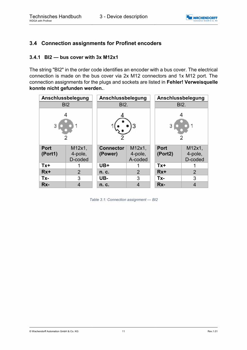
3.4.1 BI2 — bus cover with 3x M12x1
The string "BI2" in the order code identifies an encoder with a bus cover. The electrical
connection is made on the bus cover via 2x M12 connectors and 1x M12 port. The
connection assignments for the plugs and sockets are listed in Fehler! Verweisquelle
konnte nicht gefunden werden..
Anschlussbelegung
BI2
Port (Port1)
M12x1, 4-pole,
D-coded
Tx+ 1
Rx+ 2
Tx- 3
Rx- 4
Anschlussbelegung
BI2.
Connector (Power)
M12x1, 4-pole,
A-coded
UB+ 1
n. c. 2
UB- 3
n. c. 4
Anschlussbelegung
BI2.
Port (Port2)
M12x1, 4-pole,
D-coded
Tx+ 1
Rx+ 2
Tx- 3
Rx- 4
Table 3.1: Connection assignment — BI2

Technisches Handbuch WDGA with Profinet
3 - Device description
© Wachendorff Automation GmbH & Co. KG 12 Rev.1.01
3.5 LEDs and signalling
Four status LEDs on the bus cover signal the various encoder states and thus support
error diagnosis and troubleshooting in the field (see Table 3.2). The two Link Activity
LEDs (L/A) light up or flash green when the encoder is connected to another Profinet
node (PLC, switch, additional field device...) and data is being exchanged. The
STAT LED indicates the status of the fieldbus, the MOD LED the status of the encoder.
STAT LED bicolour
MOD LED bicolour
Meaning Cause
No voltage
No connection; no data exchange
Bus disconnection or master not accessible or switched off
Parametrization error, no data exchange Criterion: Data exchange correct. However, the slave does not switch to the data-exchange mode
Slave is not configured yet. Incorrect station address, but not out of range. The actual configuration of the slave differs from the nominal configuration.
System error Diagnosis exists, slave is in data-exchange mode
Data exchange, slave and operation OK
Table 3.2: LED signal
Explanation of symbols and asterisks:
LED off / LED on / LED flashing

Technisches Handbuch WDGA with Profinet
3 - Device description
© Wachendorff Automation GmbH & Co. KG 13 Rev.1.01
3.6 MAC address and IP address
Wachendorff Profinet encoders have three MAC addresses. These always start with
D4-90-E0-xx-xx-xx. The number depends on the number of ports on the integrated
three-port switch. There is one MAC address each for Port1 and Port2, as well as one
MAC address for the "internal port" to which the encoder itself is connected.
In the delivered state, the Profinet encoder has no IP address and no name. These are
defined during configuration (e.g. TIA Portal).

Technisches Handbuch WDGA with Profinet
4 - Profinet
© Wachendorff Automation GmbH & Co. KG 14 Rev.1.01
4 Profinet
4.1 Overview of functions
Our Profinet encoders support the functions shown in Fehler! Verweisquelle konnte
nicht gefunden werden.:
Functions Meaning
Conformance class CC-C
Profile Encoder Profile V4.1
Profile class Encoder Profile Class 4, as well as compatibility with Class 3
Performance Cycle time 250 μs (with clock synchronisation) and fast start-up of 1 s
Redundancy MPR and MRPD
Web server Display and configuration of parameters, firmware updates
Clock synchronisation RT, IRT and IRT isochronous
Table 4.1: Functions
4.2 GSDML modules
The modules from the current GSDML file are listed in Fehler! Verweisquelle konnte
nicht gefunden werden.:
Designation Meaning
ST0013 No multiturn, singleturn 13 bit
ST0016 No multiturn, singleturn 16 bit
MT1413 Multiturn 14 bit + singleturn 13 bit = 27 bits in total
MT1416 Multiturn 14 bit + singleturn 16 bit = 30 bits in total
MT1616 Multiturn 16 bit + singleturn 16 bit = 32 bits in total
MT3916 Multiturn 39 bit + singleturn 16 bit = 55 bits in total
Table 4.2: GSDML modules

Technisches Handbuch WDGA with Profinet
4 - Profinet
© Wachendorff Automation GmbH & Co. KG 15 Rev.1.01
4.3 Signals
Fehler! Verweisquelle konnte nicht gefunden werden. shows the signals that are
supported by Wachendorff Profinet encoders.
Signal Description Name Length (bits)
Signed
6 Velocity A NIST_A 16 Y
8 Velocity B NIST_B 32 Y
9 Sensor 1 control word G1_STW 16 -
10 Sensor 1 status word G1_ZSW 16 -
11 Sensor 1 position 1 G1_XIST1 32 N
12 Sensor 1 position 2
G1_XIST2 32 N
39 Sensor 1 position 3 G1_XIST3 64 N
80 Encoder control word 2 STW2_ENC 16 -
81 Encoder status word 2 ZSW2_ENC 16 -
238 (60000)
Sensor position preset control word
G1_XIST_PRESET_A 32 N
60001 Debug control word DEBUG_STW 16 N
60002 Debug status word DEBUG_ZSW 16 N
Table 4.3: Signals

Technisches Handbuch WDGA with Profinet
4 - Profinet
© Wachendorff Automation GmbH & Co. KG 16 Rev.1.01
4.4 Structure of the signals
NIST_A: Velocity value A
This value includes the velocity, has a width of 16 bits and is signed.
Signal NIST_A
Bits 15 … 0
Contents
15 … 0 Velocity value A Right-aligned, output in set unit (see Fehler! Verweisquelle konnte nicht gefunden werden.)
Table 4.4: Structure of signal 6 NIST_A
NIST_B: Velocity value B
This value includes the velocity, has a width of 32 bits and is signed.
Signal NIST_B
Bits 31 … 0
Contents
31 … 0 Velocity value B Right-aligned, output in set unit (see Fehler! Verweisquelle konnte nicht gefunden werden.)
Table 4.5: Structure of signal 8 NIST_B
G1_STW: Sensor 1 control word
Signal G1_STW
Bits 15 14 13 12 11 10 … 0
Contents
15 Confirm sensor error 0 = Sensor error not confirmed by controller 1 = Sensor error confirmed by controller
14 Park mode 0 = Normal operation 1 = Activate park mode
13 Cyclically query absolute position value
0 = Do not interrogate 1 = Master performs query (cyclic output of G1_XIST2) 12 Activate preset 0 = Preset not active 1 = Preset active
11 Preset mode 0 = Set preset to absolute value 1 = Move preset by value (offset)
10 … 0 Reserved, currently not used
Table 4.6: Structure of signal 9 G1_STW
To enable the encoder to respond to the requirements in G1_STW, the controller must set bit 10 to 1 in STW2_ENC.

Technisches Handbuch WDGA with Profinet
4 - Profinet
© Wachendorff Automation GmbH & Co. KG 17 Rev.1.01
G1_ZSW: Sensor 1 status word
Signal G1_ZSW
Bits 15 14 13 12 11 10 … 0
Contents
15 Sensor error Signals a sensor error and outputs a device-specific error code in G1_XIST2
14 Park mode active Confirms "Park mode". No error messages are transmitted
13 Cyclically query absolute position value
Confirms "cyclically query absolute position value"
12 Preset activated Confirms "activate preset"
11 Sensor error acknowledgement active
Signals processing of the requested sensor error acknowledgement
10 … 0 Reserved, currently not used
Table 4.7: Structure of signal 10 G1_ZSW
G1_XIST1: Sensor 1 position 1
Signal G1_XIST1
Bits 31 … 0
Contents
31 … 0 Absolute position value 1 Right-aligned
Table 4.8: Structure of signal 11 G1_XIST1
Structure of G1_XIST1 using the example of a 16-bit multiturn and a 16-bit singleturn
encoder:
31 30 29 28 27 26 25 24 23 22 21 20 19 18 17 16
M M M M M M M M M M M M M M M M
15 14 13 12 11 10 9 8 7 6 5 4 3 2 1 0
S S S S S S S S S S S S S S S S
M = multiturn / S = singleturn
This value includes the position, has a width of 32 bits and is unsigned. The encoder
parameter settings influence this position value if
"Class 4 functionality" is activated. The influence of the preset functionality can be
controlled with "G1_XIST1 Preset Control".

Technisches Handbuch WDGA with Profinet
4 - Profinet
© Wachendorff Automation GmbH & Co. KG 18 Rev.1.01
G1_XIST2: Sensor 1 position 2
Signal G1_XIST2
Bits 31 … 0
Contents
31 … 0 Absolute position value 2 Right-aligned
Table 4.9: Structure of signal 12 G1_XIST2
This value includes the position, has a width of 32 bits and is unsigned. The encoder
parameter settings influence this position value if "Class 4 functionality” is activated.
When activated, the preset functionality always has an influence on G1_XIST2.
If an error occurs, G1_XIST2 contains the error register instead of the position value.
G1_XIST3: Sensor 1 position 3
Signal G1_XIST3
Bits 63 … 0
Contents
63 … 0 Absolute position value 3 Right-aligned
Table 4.10: Structure of signal 39 G1_XIST3
This value includes the position, has a width of 64 bits and is unsigned.
It can be used if the measuring range of the encoder is larger than 32 bits. The encoder
parameter settings influence this position value if "Class 4 functionality" is activated.

Technisches Handbuch WDGA with Profinet
4 - Profinet
© Wachendorff Automation GmbH & Co. KG 19 Rev.1.01
STW2_ENC: Encoder control word 2
Signal STW2_ENC
Bits 15 … 12 11 10 9 .. 0
Contents
15 … 12 Sign-of-life from the PLC Receives a count value from 1 to 15 when isochronous transmission is activated
11 Reserved, currently not used
10 Control by PLC 0 = No control by PLC 1 = Control by PLC
9 … 0 Reserved, currently not used
Table 4.11: Structure of signal 80 STW2_ENC
ZSW2_ENC: Encoder status word 2
Signal ZSW2_ENC
Bits 15 … 12 11 10 9 .. 0
Contents
15 … 12 Sign-of-life from the encoder Sends a count value of 1 to 15 when the isochronous transmission is activated and a sign-of-life has been received from the PLC
11 … 10 Reserved, currently not used
9 PLC requests control 0 = No control by PLC 1 = Control by PLC
8 … 0 Reserved, currently not used
Table 4.12: Structure of signal 81 ZSW2_ENC
G1_XIST1_PRESET_A: Sensor position preset control word
Signal G1_XIST1_PRESET_A
Bits 31 30 … 0
Contents
31 Trigger bit Controls the transmission of the preset value 1 = Run preset
30 … 0 Preset value without sign Includes the 31-bit-wide preset value
Table 4.13: Structure of signal 238(60000) G1_XIST1_PRESET_A
This signal is intended to ensure compatibility with Siemens products. As an alternative to 238, this signal can be assigned the number 60000.

Technisches Handbuch WDGA with Profinet
4 - Profinet
© Wachendorff Automation GmbH & Co. KG 20 Rev.1.01
DEBUG_STW: Debug control word
Signal DEBUG_STW
Bits 15 … 1 0
Contents
15 … 1 0 Not used
0 Set test error Triggers the test error when set to "0"
Table 4.14: Structure of signal 60001 DEBUG_STW
DEBUG_ZSW: Debug status word
Signal DEBUG_ZSW
Bits 15 … 1 0
Contents
15 … 1 0 Not used
0 Test error active Indicates that the test error is set
Table 4.15: Structure of signal 60002 DEBUG_ZSW

Technisches Handbuch WDGA with Profinet
4 - Profinet
© Wachendorff Automation GmbH & Co. KG 21 Rev.1.01
4.5 Telegrams
The supported standard telegrams and manufacturer-specific telegrams are described
in Fehler! Verweisquelle konnte nicht gefunden werden..
For telegram 860, the manufacturer signal 238 (alternatively 60000) is used.
For telegram 59000, the manufacturer signals 60001 and 60002 are used.
Table 4.16: Telegrams
1 2 3 4 5 6 7 8 9 10
SPS -> ENCSTW2_
ENC
G1_
STW
ENC -> SPSZSW2_
ENC
G1_
ZSW
SPS -> ENCSTW2_
ENC
G1_
STW
ENC -> SPSZSW2_
ENC
G1_
ZSWNIST_A
SPS -> ENCSTW2_
ENC
G1_
STW
ENC -> SPSZSW2_
ENC
G1_
ZSW
SPS -> ENCSTW2_
ENC
G1_
STW
ENC -> SPSZSW2_
ENC
G1_
ZSW
SPS -> ENC
ENC -> SPS
SPS -> ENCSTW2_
ENC
G1_
STW
DEBUG
_STW
ENC -> SPSZSW2_
ENC
G1_
ZSW
DEBUG
_ZSW
G1_XIST2 NIST_B
G1_XIST_
PRESET_A
G1_XIST1 NIST_B
G1_XIST1 G1_XIST2
84
860
59000
G1_XIST3
83
NIST_B
Data wordDir.Nr.
81
82
G1_XIST1 G1_XIST2
G1_XIST1 G1_XIST2
G1_XIST1 G1_XIST2

Technisches Handbuch WDGA with Profinet
4 - Profinet
© Wachendorff Automation GmbH & Co. KG 22 Rev.1.01
4.6 Parameters
PNU Sub- index
Bits Function
Encod
er
pro
file
65000 Preset value
65001 1 0 Code sequence
1 Class 4 functionality
2 G1_XIST1 preset control
3 Scaling function control
4 Alarm channel control
5 Compatibility mode
2 Faults
3 Supported faults
4 Warnings
5 Supported warnings
6 Encoder profile version
8 Offset value
9 Measuring units per revolution
10 Total measuring range in measuring units
11 Velocity measuring unit
65002 Preset value 64 bit
65003 1 Offset value 64 bit
2 Measuring units per revolution 64 bit
3 Total measuring range in measuring units 64 bit
PR
OF
I drive
922 Telegram selection
925 Number of controller sign-of-life failures which may be tolerated
964 Device identification
965 Encoder profile number
970 Load parameter set
971 Transfer to non-volatile memory
972 Encoder reset
974 Base mode parameter access service identification
975 Encoder object identification
976 Load device parameter set
977 Transfer in non-volatile memory (global)
978 List of all DO-IDs
979 Sensor format
980...989 Number list of defined parameter
Devic
e-
specific
2000 Hysteresis position
2002 Extrapolation position
2003 Filter max. RPM
2004 Filter position
2005 Filter speed
Table 4.17: Supported parameters
4.6.1 Description of the most important parameters
4.6.1.1 Code sequence
Defines the counting direction of the position value in relation to the encoder shaft.
"0" means a positive counting direction of the position value with clockwise rotation of
the shaft; "1" means a positive counting direction with counter-clockwise rotation.

Technisches Handbuch WDGA with Profinet
4 - Profinet
© Wachendorff Automation GmbH & Co. KG 23 Rev.1.01
4.6.1.2 Class 4 functionality
Switches the scaling, preset and code sequence functionality on and off. When
switched on, the position values G1_XIST1, G1_XIST2 and G1_XIST3 are influenced
by the scaling and the code sequence, and G1_XIST2 and G1_XIST3 by the preset.
In addition, if "G1_XIST1 Preset control" is also activated, G1_XIST1 is also affected
by the preset, otherwise it is not.
4.6.1.3 G1_XIST1 preset control
Controls whether a preset command affects G1_XIST1 and is switched on with "0" and
off with "1". Has no function unless "Class 4 Functionality" is activated. Only affects
G1_XIST1, i.e. if the preset function is activated and the "G1_XIST2 Preset control" is
switched off, G1_XIST2 is nevertheless affected by the preset.
4.6.1.4 Scaling function control
This parameter turns the scaling functions on and off. If it is not activated, the position
values G1_XIST1, G1_XIST2 and G1_XIST3 are not affected. The scaling of the
velocity value is PROFIdrive-specific and is not influenced by the position scale. The
current setting can be read by object P65001, sub-index 1, bit 3. To use the scaling
functions, "Class 4 functionality" must be activated.
4.6.1.5 Preset value
The preset value is governed by the scaling and can be reset repeatedly and stored in
non-volatile memory via P971. By default has the preset value
has the value 0.
Setting a preset value has no effect on the position value for the time being. The preset
function is only executed by setting bit 12 in G1_STW.
4.6.1.6 Measuring units per revolution
For encoders, this parameter defines the number of increments required to resolve one
360° rotation of the encoder shaft. This parameter must be set during parametrization
(octets 5...8). The current setting can be read by object P65001, sub-index 9.
4.6.1.7 Total measuring range in measuring units
Defines the entire measuring range of the encoder, i.e. after how many increments the
position value resets to 0. For example, if "Measuring units per revolution" is 100 and
"Total measuring range" is 250, the position value will return to 0 after 2.5 revolutions
of the encoder shaft.
4.6.1.8 Velocity measuring units
This parameter defines the unit of the velocity values NIST_A and NIST_B. The
following units are possible:

Technisches Handbuch WDGA with Profinet
4 - Profinet
© Wachendorff Automation GmbH & Co. KG 24 Rev.1.01
Unit Parameter value
Increments / s 0
Increments / 100 ms 1
Increments / 10 ms 2
Rotations / min 3
Table 4.18: Velocity measuring units
4.6.1.9 Offset value
The offset value is calculated during execution of the preset and is then added to the
position value. It is stored in non-volatile memory and can be read by the encoder at
any time. The offset value can assume values within the scaled measurement range.
4.6.1.10 Hysteresis position
Parameters 2000
Meaning Hysteresis position
Data type Unsigned 8
Access RW
Values 0 … 255
Default 10
Explanation Size of the hysteresis for the position value
Table 4.19: Hysteresis position
4.6.1.11 Extrapolation position
Parameters 2002
Meaning Extrapolation position
Data type Unsigned 16
Access RW
Values 0 … 65535
Default 100
Explanation Time to be compensated for in μs "Where will the position value be in X μs?"
Table 4.20: Extrapolation position
4.6.1.12 Filter max. RPM
Parameters 2003
Meaning Filter max. RPM
Data type Unsigned 16
Access RW
Values 0 … 65535
Default 0
Explanation 0: Number of average values is constant > 0: Number of average values decreases linearly until the speed indicated here is reached
Table 4.21: Filter max. RPM

Technisches Handbuch WDGA with Profinet
4 - Profinet
© Wachendorff Automation GmbH & Co. KG 25 Rev.1.01
4.6.1.13 Filter position
Parameters 2004
Meaning Filter position
Data type Unsigned 8
Access RW
Values 0 … 255
Default 5
Explanation Number of average values for the position value
Table 4.22: Filter position
4.6.1.14 Filter speed
Parameters 2005
Meaning Filter speed
Data type Unsigned 8
Access RW
Values 0 … 255
Default 5
Explanation Number of average values for the velocity value
Table 4.23: Filter speed

Technisches Handbuch WDGA with Profinet
4 - Profinet
© Wachendorff Automation GmbH & Co. KG 26 Rev.1.01
4.7 Warnings and errors
4.7.1 Errors
Bits Meaning Sensor system error code
0 Position error All have invalid position values
5 Memory error 11
Table 4.24: Errors
4.7.2 Warnings
Bits Meaning Sensor system error code
0 Frequency exceeded -
Table 4.25: Warnings
4.7.3 G1_XIST2 error codes
G1_XIST2 Meaning Sensor system error code
0x0001 Sensor group error All have invalid position values
0x0F01 Command not supported -
0x0F02 PLC sign-of-life error -
0X0F04 Synchronisation error 13
Table 4.26: G1_XIST2 error codes

Technisches Handbuch WDGA with Profinet
5 - Web server
© Wachendorff Automation GmbH & Co. KG 27 Rev.1.01
5 Web server
5.1 General information
Profinet encoders have a web server that lets you view specific information and
configure certain settings. To access the web server, enter its IP address into a
browser of your choice (Internet Explorer, Firefox, etc.). To do so, connect the encoder
to your computer using an Ethernet cable (M12 connector on the encoder and RJ45
connector on the PC). Ensure that your PC is in the same IP address range as the
encoder.
Example configuration: IP address of the encoder: 192.168.0.1 IP address of the PC: 192.168.0.100 Subnet address of the PC: 255.255.255.0
Once this has been done, the encoder's homepage opens (information overview).
The following sub-sections cover the various views within the web server and the
available functions.
5.2 Information
5.2.1 Overview
Figure 5.1: Web server — overview

Technisches Handbuch WDGA with Profinet
5 - Web server
© Wachendorff Automation GmbH & Co. KG 28 Rev.1.01
The overview displays the following information:
Device type: name of the encoder
Serial number: device number of the encoder
Operating time in hours: number of operating hours
Protocol: Profinet IO
Device status: on or off state
Status stack: Online or offline
MAC devices: MAC address of the encoder
MAC Port 1: MAC address of Ethernet port 1
MAC Port 2: MAC address of Ethernet port 2
IP address: IP address of your Profinet encoder
Network mask: the subnet mask of your Profinet encoder
Gateway: the gateway of your Profinet encoder
The update rate of the web page is fixed at 10 seconds and cannot be changed. The
message "Updating Data" in the upper-right corner of the field in which the update time
is displayed indicates that the data is being updated.
You can change the language of the web server after accessing it.
After switching inside a sub-screen, the web server restarts from the start screen.

Technisches Handbuch WDGA with Profinet
5 - Web server
© Wachendorff Automation GmbH & Co. KG 29 Rev.1.01
5.2.2 Diagnosis
Figure 5.2: Diagnostic page
Exception
Possible causes of errors are displayed here. If you see an error here, please either
contact us or refer to the manual for possible causes.
Fieldbus
CPU Load: this shows the CPU utilisation of the encoder during operation.
Interface:
o Type: the protocol is displayed here; Ethernet
o State: the mode is specified here. Only static IP is specified. DHCP mode
is not possible.
Port 1 and Port 2
o Link: indicates whether the port is active. Link=> up or down
o Connection: max. speed 100Mbit/FD
o Negotiation: allows two interconnected Ethernet ports to negotiate
independently and configure the maximum possible speed.
o Cable length: when using IRT mode, the cable length specified in the TIA
Portal is displayed.

Technisches Handbuch WDGA with Profinet
5 - Web server
© Wachendorff Automation GmbH & Co. KG 30 Rev.1.01
5.2.3 Versions
Figure 5.3: Versions
Here you can find information about the individual versions:
Application
SDAI
Stack
MAC
Sensor
U2A

Technisches Handbuch WDGA with Profinet
5 - Web server
© Wachendorff Automation GmbH & Co. KG 31 Rev.1.01
5.3 Configuration
5.3.1 Network
Figure 5.4: Network settings
You can change the device name, IP address, network mask and gateway here.
Please note that this data should only be modified when the system is not in operation.
5.3.2 Encoder
Figure 5.5: Encoder information
You can check the following parametrized values for the encoder here:
Resolution singleturn
Total measuring range
Preset value
Code sequence

Technisches Handbuch WDGA with Profinet
5 - Web server
© Wachendorff Automation GmbH & Co. KG 32 Rev.1.01
5.3.3 Firmware Update
Figure 5.6: Firmware update
The current firmware version of the encoder is displayed. If a new firmware version is
available, you can update the encoder's firmware here.
Please note that the firmware must only be updated when the system is not in operation.
Do not cut off the power supply or disconnect the network cable while performing a firmware update.
To update the firmware of the encoder, choose the correct .bin file by clicking the
“Browse…”-Button (see Figure 5.7: Firmware update - choose file).
Figure 5.7: Firmware update - choose file
Technisches Handbuch WDGA with Profinet
5 - Web server
© Wachendorff Automation GmbH & Co. KG 33 Rev.1.01
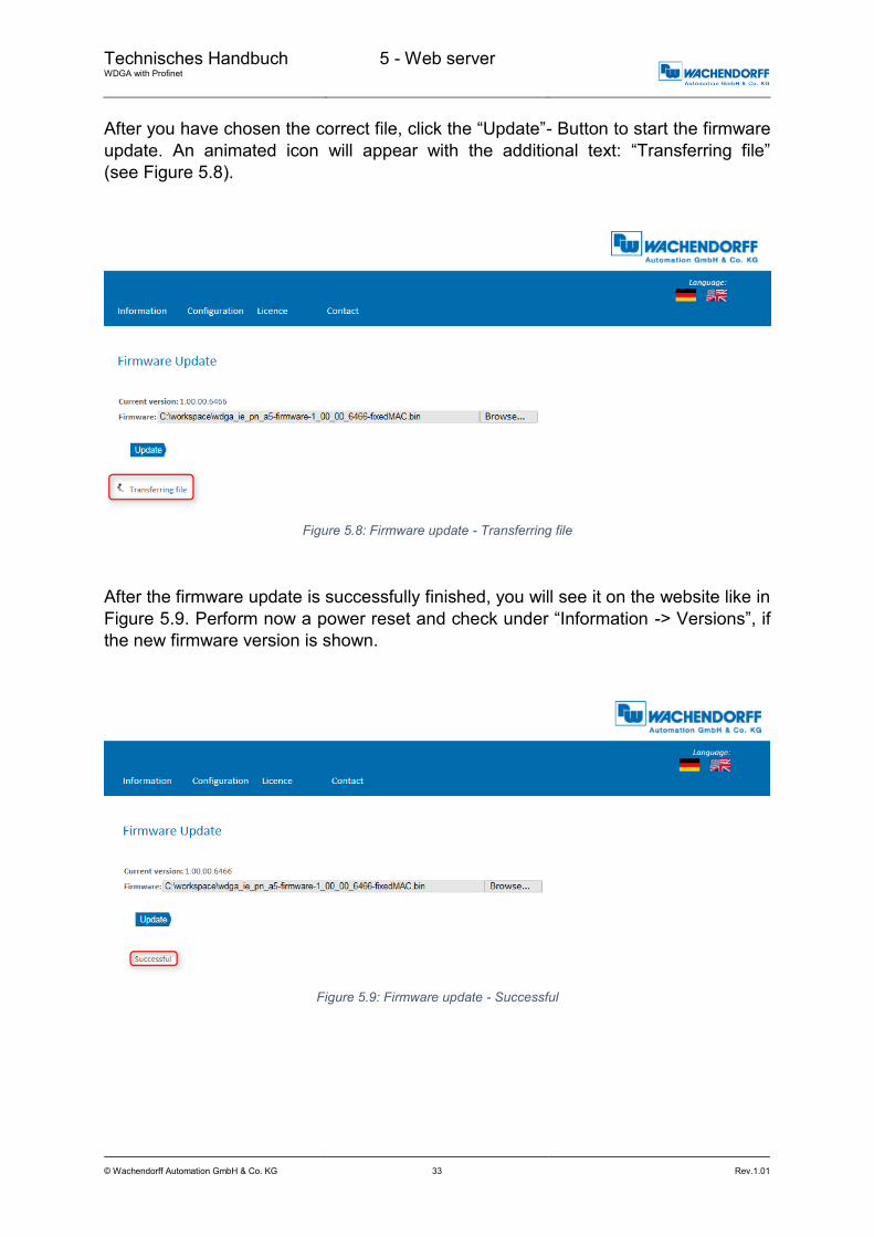
After you have chosen the correct file, click the “Update”- Button to start the firmware
update. An animated icon will appear with the additional text: “Transferring file”
(see Figure 5.8).
Figure 5.8: Firmware update - Transferring file
After the firmware update is successfully finished, you will see it on the website like in
Figure 5.9. Perform now a power reset and check under “Information -> Versions”, if
the new firmware version is shown.
Figure 5.9: Firmware update - Successful

Technisches Handbuch WDGA with Profinet
5 - Web server
© Wachendorff Automation GmbH & Co. KG 34 Rev.1.01
In case of a failure during the firmware update process (see Figure 5.10) please double
check that you choose the correct firmware file. Do a power reset and repeat the whole
firmware update process. In case of a power loss during the update, the encoder may
not respond to any request any more. If this happens, please contact our support team.
Figure 5.10: Firmware update - Failed
5.4 Licence information
Figure 5.11: Licence information
This view contains the current safety instructions as well as software packages
containing firmware. You can download the source code of these packages using the
link on this website.
Technisches Handbuch WDGA with Profinet
5 - Web server
© Wachendorff Automation GmbH & Co. KG 35 Rev.1.01
5.5 Contact
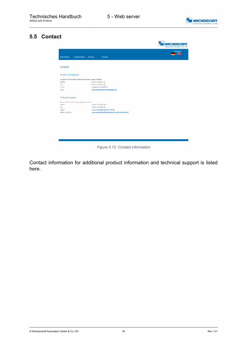
Figure 5.12: Contact information
Contact information for additional product information and technical support is listed
here.

Technisches Handbuch WDGA with Profinet
6 - Commissioning
© Wachendorff Automation GmbH & Co. KG 36 Rev.1.01
6 Commissioning
6.1 General information
This section contains two configuration examples for Wachendorff Profinet encoders.
The first example is shown with version 14 of the TIA portal, the second with Step 7
V5.5 SP4.
6.2 Integration into a TIA project
Connect the encoder to your controller.
Connect the encoder's power supply.
To integrate the encoder into your TIA portal project, start your TIA portal, open the
required project and switch to the project view by pressing the "Project view" button
(see Figure 6.1).
Figure 6.1: Switching to project view
Technisches Handbuch WDGA with Profinet
6 - Commissioning
© Wachendorff Automation GmbH & Co. KG 37 Rev.1.01
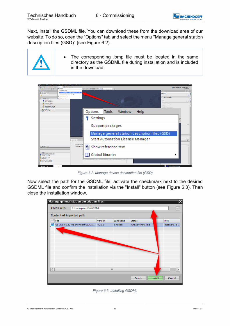
Next, install the GSDML file. You can download these from the download area of our
website. To do so, open the "Options" tab and select the menu "Manage general station
description files (GSD)" (see Figure 6.2).
The corresponding .bmp file must be located in the same directory as the GSDML file during installation and is included in the download.
Figure 6.2: Manage device description file (GSD)
Now select the path for the GSDML file, activate the checkmark next to the desired
GSDML file and confirm the installation via the "Install" button (see Figure 6.3). Then
close the installation window.
Figure 6.3: Installing GSDML

Technisches Handbuch WDGA with Profinet
6 - Commissioning
© Wachendorff Automation GmbH & Co. KG 38 Rev.1.01
From the "Project tree" column on the left of the TIA portal, select the
"Devices & networks" tab (see Figure 6.4). The hardware view opens and the hardware
catalogue is now visible in the right-hand column.
Figure 6.4: Switch to Devices & Networks
Add the encoder to your hardware configuration. To do so, open the following path at
the right edge of the screen: "Other field devices / Profinet IO / Encoders / Wachendorff
Automation GmbH & Co. KG / WDGA / Wachendorff Encoder" (see Figure 6.5).
Figure 6.5: Hardware catalogue
Now "drag" the encoder onto the "Profinet IO system". This encoder is now displayed
in the hardware view. Connect the encoder to the controller by dragging the encoder
port onto the appropriate controller port. The result is shown in Figure 6.6.
Figure 6.6: Network view

Technisches Handbuch WDGA with Profinet
6 - Commissioning
© Wachendorff Automation GmbH & Co. KG 39 Rev.1.01
Select the encoder and switch to the "Device overview" tab. Enter a meaningful device
name by double-clicking the default name (see Figure 6.7).
Figure 6.7: Change device name
Configure the encoder by selecting the corresponding configuration from the hardware
catalogue and dragging it onto "Slot 1" (see Figure 6.8).
Figure 6.8: Select module
Now select the desired telegram for communication. To do so, proceed as in the
previous step. Select "Slot 1 2". The various telegrams can be found under "Profile" in
the "Submodules" tab (see Figure 6.9).
Figure 6.9: Select telegram

Technisches Handbuch WDGA with Profinet
6 - Commissioning
© Wachendorff Automation GmbH & Co. KG 40 Rev.1.01
You can also set the corresponding I/O addresses. To do so, double-click on the
respective field and change the address (see Figure 6.10).
Figure 6.10: Change the I/O addresses
Click on your PLC in the project navigation window and load the configuration by
clicking the "Download to device" button (see Figure 6.11).
Figure 6.11: Download to device
Switch back to the "Devices and networks" view and assign the Profinet device name
to the encoder as shown in the configuration on page 39. To do so, select the encoder
(single mouse click) and select the "Assign device name" option (see Figure 6.12).
Assign a name to the encoder. Then select your PG/PC interface and the type and
click on "Update list" (see Figure 6.13).
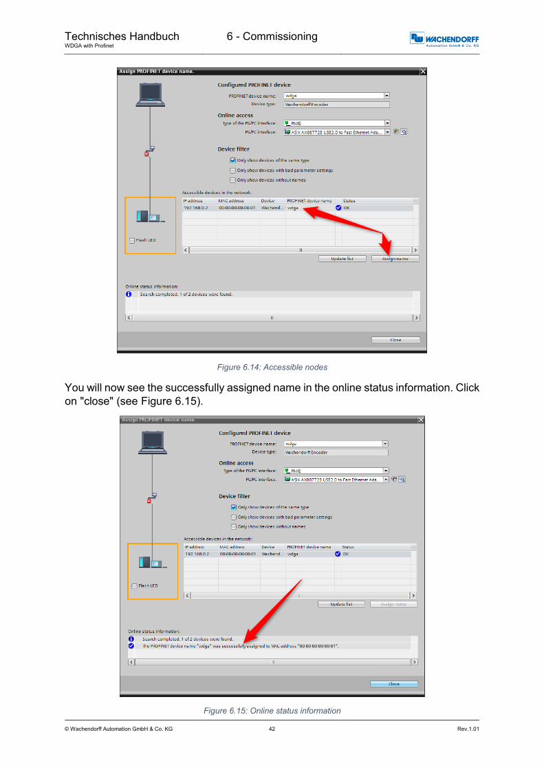
All devices are now displayed under "Accessible devices in the network". Select your
encoder and click on "Assign name" (see Figure 6.14).

Technisches Handbuch WDGA with Profinet
6 - Commissioning
© Wachendorff Automation GmbH & Co. KG 41 Rev.1.01
Figure 6.12: Assigning device names
Figure 6.13: Name and PG interface
Technisches Handbuch WDGA with Profinet
6 - Commissioning
© Wachendorff Automation GmbH & Co. KG 42 Rev.1.01
Figure 6.14: Accessible nodes
You will now see the successfully assigned name in the online status information. Click
on "close" (see Figure 6.15).
Figure 6.15: Online status information

Technisches Handbuch WDGA with Profinet
6 - Commissioning
© Wachendorff Automation GmbH & Co. KG 43 Rev.1.01
You can use a variable table to display the encoder's I/O data for test purposes. To do
so, open the default tag table (see Figure 6.16) and enter the corresponding address
for the position value. You can then click on "Show all" to see the position value
(see Figure 6.17 and Figure 6.18).
Example:
Figure 6.16: PLC variables
Figure 6.17: Show all
Figure 6.18: Default tag table

Technisches Handbuch WDGA with Profinet
6 - Commissioning
© Wachendorff Automation GmbH & Co. KG 44 Rev.1.01
6.3 Scaling function
In order to set a different number of steps / revolutions or revolutions than the one
given in the GSDML file, the scaling function must be activated. The following two
examples explain this for a singleturn and a multiturn encoder. It is assumed that you
have already configured the encoder and your PLC in the TIA portal.
6.3.1 Example scaling function singleturn 16-bit to 12-bit
Double-click on the image of the encoder in the network view of "Devices and
Networks". (s. Figure 6.19)
Figure 6.19: Example of commissioning
Figure 6.20 now shows a rotary encoder configured as 16-bit singleturn. In the "Device
overview" we click on the field "MAP".
Figure 6.20: Device overview - MAP

Technisches Handbuch WDGA with Profinet
6 - Commissioning
© Wachendorff Automation GmbH & Co. KG 45 Rev.1.01
The "Assembly parameters" which we click on will then appear in the "Properties"
under "Device overview" in the "General" tab. (s. Figure 6.21)
Figure 6.21: Assembly parameters
The default settings of the 16-bit singleturn encoder are shown in Figure 6.22.
Figure 6.22: Default assembly parameters 16-Bit Singleturn
Technisches Handbuch WDGA with Profinet
6 - Commissioning
© Wachendorff Automation GmbH & Co. KG 46 Rev.1.01
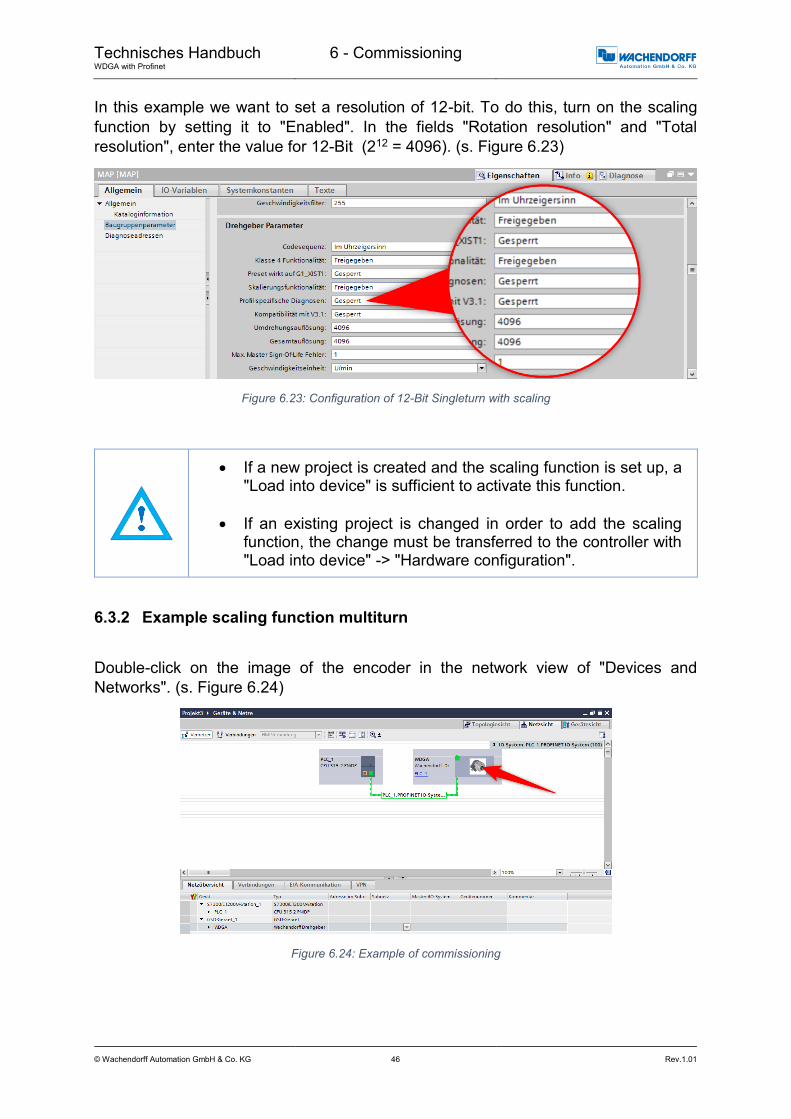
In this example we want to set a resolution of 12-bit. To do this, turn on the scaling
function by setting it to "Enabled". In the fields "Rotation resolution" and "Total
resolution", enter the value for 12-Bit (212 = 4096). (s. Figure 6.23)
Figure 6.23: Configuration of 12-Bit Singleturn with scaling
If a new project is created and the scaling function is set up, a "Load into device" is sufficient to activate this function.
If an existing project is changed in order to add the scaling function, the change must be transferred to the controller with "Load into device" -> "Hardware configuration".
6.3.2 Example scaling function multiturn
Double-click on the image of the encoder in the network view of "Devices and
Networks". (s. Figure 6.24)
Figure 6.24: Example of commissioning

Technisches Handbuch WDGA with Profinet
6 - Commissioning
© Wachendorff Automation GmbH & Co. KG 47 Rev.1.01
Figure 6.25 now shows a rotary encoder configured as 16-bit singleturn and 43-bit
multiturn. In the "Device overview" we click on the field "MAP".
Figure 6.25: Device overview - MAP
The "Assembly parameters" which we click on will then appear in the "Properties"
under "Device overview" in the "General" tab. (s. Figure 6.26)
Here you can also see the default settings of a 43-bit multiturn and 16-bit singleturn
encoder.
Figure 6.26: Assembly parameters

Technisches Handbuch WDGA with Profinet
6 - Commissioning
© Wachendorff Automation GmbH & Co. KG 48 Rev.1.01
In this example we want to set a resolution of 360 steps/revolution and 10 countable
revolutions (10 x 360 steps = 3600 steps total resolution).
To do this, turn on the scaling function by setting it to "Enabled". Enter 360 in the field
"Revolution resolution" and 3600 in the field "Total resolution". (s. Figure 6.27)
Figure 6.27: Configuration of 360 Steps/revolution and 10 revolutions
If a new project is created and the scaling function is set up, a "Load into device" is sufficient to activate this function.
If an existing project is changed in order to add the scaling function, the change must be transferred to the controller with "Load into device" -> "Hardware configuration".
6.3.3 Executing a preset
First set whether the preset should also act on G1_XIST1. For the following
explanations it is assumed that telegram 81 is used and that the input data (from the
view of the controller) are present at input addresses 0…11 and the output data at
output addresses 0…3. In this case the following data contents exist:
Data Type Adress Adressing
STW2_ENC W Encoder control word Q0..Q1 QW0
G1_STW W Axis control word Q2..Q3 QW2
ZSW2_ENC W Status word of the encoder I0..I1 IW0
G1_ZSW W Status word of the axis I2..I3 IW2
G1_XIST1 DW Processdata I4..I7 ID4
G1_XIST2 DW Processdata or error register I8..I11 ID8
Table 6.1: Data content for Example

Technisches Handbuch WDGA with Profinet
6 - Commissioning
© Wachendorff Automation GmbH & Co. KG 49 Rev.1.01
Set the encoder to normal, controlled operation during startup or manually via an
observation table. To do this, set STW2_ENC bit 10 "Control by PLC" to TRUE.
Figure 6.28: set STW2_ENC bit 10 to TRUE
If successful, the encoder sets the flag ZSW2_ENC Bit 9 "Control requested". Then
set G1_STW bit 13 "Request absolute value cyclically" to TRUE.
Figure 6.29: set G1_STW bit 13 to TRUE
If successful, the encoder sets the flag G1_ZSW Bit 13 "Transmit absolute value
cyclically" and G1_XIST2 contains the same value as G1_XIST1.
Finally, you can select the preset mode via G1_STW Bit 11 "Home position mode"
(default 0 = absolute, 1 = relative).
Figure 6.30: G1_STW Bit 11 default 0 = absolute

Technisches Handbuch WDGA with Profinet
6 - Commissioning
© Wachendorff Automation GmbH & Co. KG 50 Rev.1.01
The preset to the pre-defined preset value (0 by default, adjustable via PNU 65000 or
PNU 65002) can now be executed with a pulse to G1_STW Bit 12 "Request of home
position" (set and reset).
Figure 6.31: set and reset G1_STW Bit 12
G1_XIST2 then contains the pre-defined preset value. If "Preset affects G1_XIST1",
this also applies to G1_XIST1.
When the preset is executed, an offset value is calculated and stored in the rotary encoder. This value is loaded with each reset so that this setting is retained even after a reset. The offset value is reset as soon as the scaling of the encoder changes or another module is selected. This ensures that an offset value is not used that may not match the set scaling.
The preset is executed by the encoder on a rising edge to G1_STW bit 12; it is confirmed on the following falling edge. Only then the preset can be executed again.
6.3.4 Resetting a preset
To undo or reset the preset, simply set the preset with the preset value 0 and G1_STW
bit 11 "Home position mode" to 1 = relative. This sets the internal offset value to 0.

Technisches Handbuch WDGA with Profinet
6 - Commissioning
© Wachendorff Automation GmbH & Co. KG 51 Rev.1.01
6.4 Integration into a Step 7 project
Connect the encoder to your controller.
Connect the encoder's power supply.
To integrate the encoder into your SIMATIC Manager project, double-click the
"Hardware" button to start the hardware configuration tool (see Figure 6.32).
Figure 6.32: SIMATIC Manager
Next, install the GSDML file. You can download this from www.wachendorff-
automation.de. To do so, open the "Extras" tab and select "Install GSD file"
(see Figure 6.33).
The corresponding .bmp file must be located in the same directory as the GSDML file during installation and is included in the download.
Figure 6.33: Installing the GSDML file

Technisches Handbuch WDGA with Profinet
6 - Commissioning
© Wachendorff Automation GmbH & Co. KG 52 Rev.1.01
Now select the path for the GSDML file, select the desired GSDML file and confirm the
installation via the "Install" button (see Figure 6.34). Then close the installation window.
Figure 6.34: Installing GSDML
Add the encoder to your hardware configuration. To do so, open the following path at
the right edge of the screen (see Figure 6.35):
"PROFINET IO/Additional Field Devices/Encoders/WDGA/Wachendorff Encoder".
Figure 6.35: Hardware catalogue

Technisches Handbuch WDGA with Profinet
6 - Commissioning
© Wachendorff Automation GmbH & Co. KG 53 Rev.1.01
Now "drag" the encoder onto the "Profinet IO system". The encoder is then displayed
in the hardware view (see Figure 6.36). Enter a meaningful device name for the
configured encoder by double-clicking the encoder symbol (see Figure 6.37).
Figure 6.36: Hardware view
Figure 6.37: Assign a device name
Now select the encoder's "Properties". To do this, single-click on the encoder
(see Figure 6.38) and drag the desired properties (see Figure 6.39 No. 1) via drag-
and-drop from the hardware catalogue to "Slot 1", which is now highlighted green
(see Figure 6.40). Select the desired telegram for communication (see Figure 6.39 No.
2). The various telegrams can be found in the "Profiles" sub-menu. Drag the telegram
to slot 1.2 (see Figure 6.41).

Technisches Handbuch WDGA with Profinet
6 - Commissioning
© Wachendorff Automation GmbH & Co. KG 54 Rev.1.01
Figure 6.38: Select via single mouse click
Figure 6.39: Select the properties and the telegram
Figure 6.40: Slot 1, highlighted green
Figure 6.41: Slot 1.2 with inserted telegram 81

Technisches Handbuch WDGA with Profinet
6 - Commissioning
© Wachendorff Automation GmbH & Co. KG 55 Rev.1.01
You can also set the corresponding I/O addresses. To do so, double-click on the
respective field (see Figure 6.42) and change the addresses in the "Addresses" tab
(see Figure 6.43).
Figure 6.42: Change the I/O addresses
Figure 6.43: "Addresses" tab
Save the configuration by clicking the "Save and transmit" button and load it into your
PLC ("Download to module").
Figure 6.44: Save and transmit — Download to module
You can use a variable table to display the encoder's I/O data for test purposes
(see Figure 6.45 and Figure 6.46).
Figure 6.45: Variable table

Technisches Handbuch WDGA with Profinet
6 - Commissioning
© Wachendorff Automation GmbH & Co. KG 56 Rev.1.01
Figure 6.46: HEX position value

Technisches Handbuch WDGA with Profinet
7 - Technical data
© Wachendorff Automation GmbH & Co. KG 57 Rev.1.01
7 Technical data
7.1 Properties
Interfaces 2x M12 ports 4-pole D-coded
1x M12 connector 4-pole A-coded
Profinet data rate Max. 100 Base-TX
Diagnostic LEDs Data traffic and connection monitoring:
L/A1: Port 1, L/A2: Port 2
Status LEDs Status display for encoder and bus
STAT, MOD
Operating temperature -40°C to +85°C
Storage temperature -40°C to +125 °C
Operating voltage 10 VDC to 32 VDC
Current consumption typ. 125 mA
Power consumption typ. 3 W
Weight WDGA 58B, 58F: approx. 700 g
WDGA 58E: approx. 410 g
Housing Flange material: Aluminium
Flange material (rear): Steel housing, chromium-plated, magnetically shielded
Connection hood: Die-cast aluminium, powder-coated
7.2 Dimensions
7.2.1 WDGA 58B
Figure 7.1: Dimensions WDGA 58B
D = 6, L = 12, d = 5.3 shaft with flat
D = 8, L = 20, d = 7.5 shaft with flat
D = 10, L = 20, d = 10 shaft without flat
D = 3/8”, L = 20, d = 8.3 shaft with flat
*option full IP67 version: D = 10 mm
D = 10, L = 20, d = 9 shaft with flat

Technisches Handbuch WDGA with Profinet
7 - Technical data
© Wachendorff Automation GmbH & Co. KG 58 Rev.1.01
7.2.2 WDGA 58F
Figure 7.2: Dimensions WDGA 58F
7.2.3 WDGA 58E
Figure 7.3: Dimensions WDGA 58E
D = 12, 14, 15
6, 6.35 (1/4”), 7, 8, 9.35 (3/8”), 10
with adapter sleeve

Technisches Handbuch WDGA with Profinet
8 - Technical support
© Wachendorff Automation GmbH & Co. KG 59 Rev.1.01
8 Technical support
Technical application advisor
Do you have any questions about this product?
Our technical application advisor will be pleased to help you.
Tel.: +49 (0) 67 22 / 99 65 414
Fax: +49 (0) 67 22 / 99 65 70
E-Mail: [email protected]
Notes: