techniques for strong partitioning of vme- …younis/publications/ijpdsn00/vme... · 1 techniques...
TRANSCRIPT
1
TECHNIQUES FOR STRONG PARTITIONING OF VME-BASED MULTIPROCESSOR SYSTEMES
Mohamed F. Younis* Mohamed Aboutabl**
* Honeywell International Inc., Advanced Systems Technology Group 9140 Old Annapolis Road/MD 108, Columbia, MD 21045, USA
** Wireless Network Group, Lucent Technologies 550 Clark Dr., Mt. Olive, NJ 07828
Abstract
The VME bus has been widely used in embedded systems due to its rigorous design, stable
specifications, and the fact that it has enjoyed a strong support from multiple vendors. However, the
VME bus still lacks some features that are essential to safety-critical systems, such as avionics. In
this paper, we address the issue of lacking the capability of fault containment in the current
specification of the VME bus and propose a strong partitioning protocol for inter-processor
communication for a VME-based system. This protocol enforces fault containment without any
modifications to the VME hardware. The design and implementation of a proof-of-concept prototype
is presented. Numerous software-based as well as hardware-based fault injection experiments have
been conducted to demonstrate the resilience of the system to any fault propagation attempts. The
performance of the strong partitioning protocol is evaluated and compared to alternative techniques
for multiprocessing on the VME bus. Finally, the benefits of this technology for a space launch
vehicle and commercial avionics are discussed.
Keywords: Fault Containment, Safety-Critical Systems, Distributed Processing, Inter-Processor
Communication, The VME Bus System, Integrated Modular Avionics.
1. Introduction
Recently, a new trend towards the use of commercial-of-the-shelf (COTS) solutions has emerged and
found a strong acceptance in the real-time embedded systems arena. The driving force behind this
2
trend was, and still is, lowering the production cost and time-to-market cycle associated with the
traditional proprietary designs. The COTS-based solutions decrease the development and
maintenance cost as a result of the mass production of components, the reduced levels of spares, and
the competition among different vendors.
Meanwhile, the avionics industry has endorsed a new approach for systems design, namely the
Integrated Modular Avionics (IMA) [1]. Multiple functions are integrated in a modular system thus
sharing common resources and promoting the reusability of existing subsystems. However, function
integration increases the risk of the failure of multiple functions due to a fault in one of the system
components. In an IMA environment, an application might share a resource with others and thus, its
correct operation becomes dependent on their use of the resource. When multiple avionics
application modules share a resource such as memory or a communication bus, partitioning is
particularly challenged in the way applications observe access protection and usage quota for that
resource. Therefore, access to shared resources needs to be carefully controlled in an IMA both
spatially and temporally.
Thus, the IMA approach inherently requires strong partitioning among the different modules
coexisting within the same system. Strong partitioning calls for well-defined boundaries among
modules to ensure the continuity of operation in the presence of partial failure [2]. Containing the
effects of faults is very crucial for the integrated environment to guarantee that a faulty component
may not cause other components to fail and risk generating a total system failure. Strong partitioning
also facilitates the modification, debugging, integration, and certification of the modules involved in
building a system with the level of complexity found in the avionics industry.
Using COTS components in the implementation of integrated modular avionics brings the
challenge of guaranteeing strong partitioning, a feature which COTS products usually are not
designed to have. Since COTS components will lose their cost advantage if they have to be modified
to fit in an IMA design, special techniques need to be used to maintain strong partitioning. This
paper presents techniques for spatially partitioning of COTS-based VME (VERSA Module
Eurocard) systems for integrated modular avionics. To the best of our knowledge obstacles for strong
partitioning of the VME bus have not been previously identified or addressed in the literature. While
strong partitioning generally covers the temporal and spatial aspects, in this paper we focus only on
3
spatial partitioning of the VME bus system, and thus our reference to strong partitioning in the
balance of the paper means only the spatial aspect of it.
In the following subsections, we discuss the background for our research work and describe the
fault model addressed by this paper. We also include a brief overview of the VME bus and shed the
light on its inability to stop faults in one module from affecting other healthy modules in a
multiprocessor setup. Section 2 presents techniques for strong partitioning of a VME system. The
implementation of these techniques in a test environment is described in section 3. Fault injection
experiments are discussed in section 4, followed by an analysis of performance measurements in
section 5. Section 6 discusses related work. Section 7 concludes the paper and discusses the benefits
of the work in current aerospace programs within Honeywell.
1.1 Motivation
The backplane bus is one of the most important components in integrated modular avionics. While
many backplane buses have been proposed, only a few are actually used. Selecting a backplane bus is
influenced by many design and engineering factors, such as performance, reliability, and fault-
tolerance. Although such issues are very important to ensure certain levels of safety of commercial
jet aircraft and high availability of military aircraft, the cost of the bus and associated modules is a
major concern.
Most of the currently available dependable backplane bus systems, such as ARINC 659 [3], are
expensive and supplied by very few vendors. It is clear that there is a need for an affordable bus
system that provides the required level of dependability and complies with the IMA design
methodology. The VME bus system [4] is a prime candidate because it is both rigorously defined and
widely supported. In addition, there is an expanding selection of VME bus modules (boards) and
vendors offering competitive prices and continuous support. Moreover, the VME bus provides an
open architecture that facilitates the integration of multiple vendors’ modules. Such a feature makes
the VME bus an attractive choice for integrated avionics on highly visible projects such as the
Venture Star space launch vehicle, supported by NASA for its 21st century space shuttle [5].
However, as discussed in Section 1.3, the VME bus architecture does not impose strong
partitioning. This paper focuses only on spatial partitioning of the VME system. The VME
4
architecture allows faults to propagate from one module to the other. For example, a faulty module
can perform a wild-write, which corrupts the shared memory area and disturbs the computation on
other modules [6]. Containing the effects of faults is very crucial for the integrated environment to
guarantee that a faulty component may not cause other components to fail and risk generating a total
system failure. For instance, in an ideal IMA-based avionics, a failure in the cabin temperature
control system must not negatively influence critical flight control systems such as the flight
manager. Lacking the capability to isolate faults limits the use of the VME bus in mission-critical
applications.
Fault containment is not the only capability that the VME bus lacks to be fault tolerant. There are
weaknesses in both fault detection and recovery as well. The bus structure, as explained in section
1.2, allows isolation of modules and even a total bus break down because of a failure in the
centralized bus controller [7]. While the VME bus lacks such fault detection and recovery
capabilities to be fault tolerant, the potential of fault propagation over the bus must be prevented to
minimize the possibility of complete system failure.
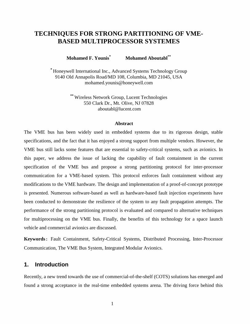
1.2 An Overview of The VME bus
The VME bus is multi-processor computer
architecture. It handles data transfer rates in
excess of 40 Mbytes/sec using parallel data
transfer. Although the origin of the term 'VME'
has never been formally defined, it is
commonly used to refer to VERSA Module
Eurocard standard which is a combination of
the Motorola VERSAbus electrical standard,
and the Eurocard mechanical form factor [4].
The VME bus is asynchronous and non-multi
used to coordinate data transfer. Every module (bo
interfacing with the bus. Data is passed between
where the slowest module participating in a cycle
in the VME bus provides reasonable capabilities to
System controller VME Backplane
Daisy-chained interrupt ack. and bus grant
Figure 1: The VME bus architecture
plexed. Because it is asynchronous no clocks are
ard) includes a VME chip that hosts the logic for
modules using interlocked handshaking signals
sets the cycle speed. Using asynchronous protocol
integrate products from various vendors.
5
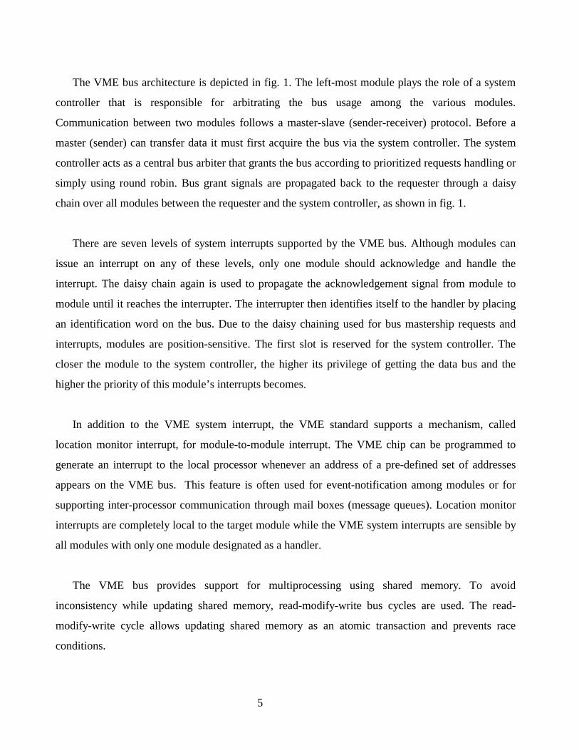
The VME bus architecture is depicted in fig. 1. The left-most module plays the role of a system
controller that is responsible for arbitrating the bus usage among the various modules.
Communication between two modules follows a master-slave (sender-receiver) protocol. Before a
master (sender) can transfer data it must first acquire the bus via the system controller. The system
controller acts as a central bus arbiter that grants the bus according to prioritized requests handling or
simply using round robin. Bus grant signals are propagated back to the requester through a daisy
chain over all modules between the requester and the system controller, as shown in fig. 1.
There are seven levels of system interrupts supported by the VME bus. Although modules can
issue an interrupt on any of these levels, only one module should acknowledge and handle the
interrupt. The daisy chain again is used to propagate the acknowledgement signal from module to
module until it reaches the interrupter. The interrupter then identifies itself to the handler by placing
an identification word on the bus. Due to the daisy chaining used for bus mastership requests and
interrupts, modules are position-sensitive. The first slot is reserved for the system controller. The
closer the module to the system controller, the higher its privilege of getting the data bus and the
higher the priority of this module’s interrupts becomes.
In addition to the VME system interrupt, the VME standard supports a mechanism, called
location monitor interrupt, for module-to-module interrupt. The VME chip can be programmed to
generate an interrupt to the local processor whenever an address of a pre-defined set of addresses
appears on the VME bus. This feature is often used for event-notification among modules or for
supporting inter-processor communication through mail boxes (message queues). Location monitor
interrupts are completely local to the target module while the VME system interrupts are sensible by
all modules with only one module designated as a handler.
The VME bus provides support for multiprocessing using shared memory. To avoid
inconsistency while updating shared memory, read-modify-write bus cycles are used. The read-
modify-write cycle allows updating shared memory as an atomic transaction and prevents race
conditions.
6
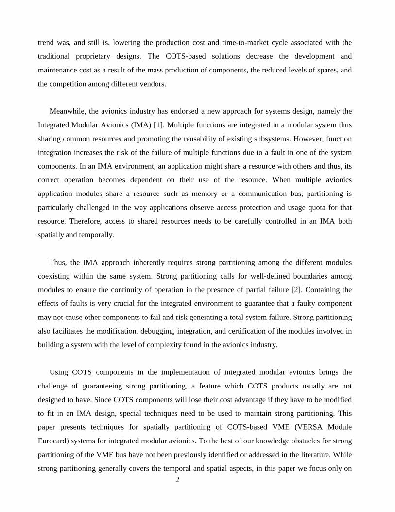
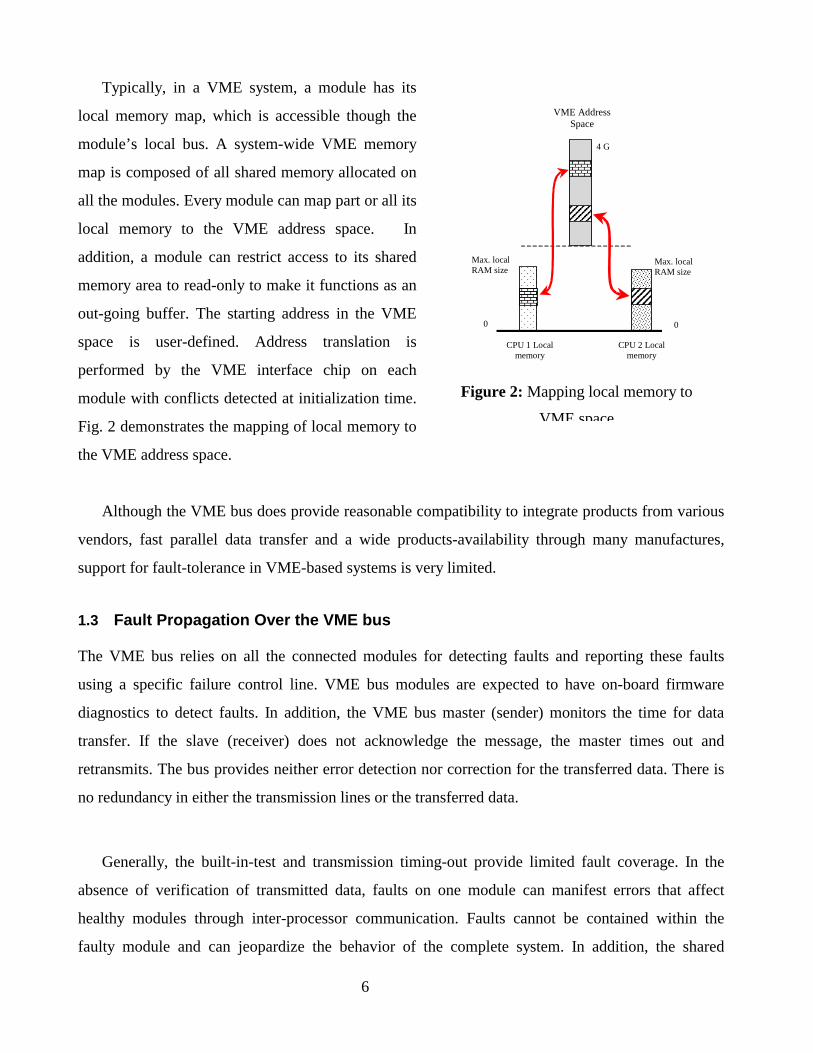
Typically, in a VME system, a module has its
local memory map, which is accessible though the
module’s local bus. A system-wide VME memory
map is composed of all shared memory allocated on
all the modules. Every module can map part or all its
local memory to the VME address space. In
addition, a module can restrict access to its shared
memory area to read-only to make it functions as an
out-going buffer. The starting address in the VME
space is user-defined. Address translation is
performed by the VME interface chip on each
module with conflicts detected at initialization time.
Fig. 2 demonstrates the mapping of local memory to
the VME address space.
Although the VME bus does provide reasonable co
vendors, fast parallel data transfer and a wide produ
support for fault-tolerance in VME-based systems is ver
1.3 Fault Propagation Over the VME bus
The VME bus relies on all the connected modules fo
using a specific failure control line. VME bus modu
diagnostics to detect faults. In addition, the VME bus
transfer. If the slave (receiver) does not acknowled
retransmits. The bus provides neither error detection no
no redundancy in either the transmission lines or the tra
Generally, the built-in-test and transmission timin
absence of verification of transmitted data, faults on
healthy modules through inter-processor communicat
faulty module and can jeopardize the behavior of th
CPU 1 Localmemory
VME AddressSpace
0
Max. localRAM size
4 G
Max. localRAM size
0
CPU 2 Localmemory
Figure 2: Mapping local memory to
VME space
mpatibility to integrate products from various
cts-availability through many manufactures,
y limited.
r detecting faults and reporting these faults
les are expected to have on-board firmware
master (sender) monitors the time for data
ge the message, the master times out and
r correction for the transferred data. There is
nsferred data.
g-out provide limited fault coverage. In the
one module can manifest errors that affect
ion. Faults cannot be contained within the
e complete system. In addition, the shared
7
memory model cannot prevent a wild-write by a faulty module, which can corrupt the memory of
other healthy module [6]. Such a problem is usually referred to as fault propagation from one faulty
module to other healthy modules.
In addition to fault propagation problems, the VME bus system allows a single point of failure by
using a centralized mastership control of the bus. The system controller organizes all
communications among modules. Faults in the system controller can bring down the whole system.
Moreover, the reliability of daisy chain mechanism is questionable. Each module either accepts the
bus grant or passes it over to the next module. Failure of one module might break the chain and
affect other modules. Breaking the chain can prevent other modules from getting mastership of the
bus and from reacting to interrupts. Communication among modules can be highly affected and the
whole system can break down.
From the above discussion, we conclude that the VME bus needs enhancements to strengthen its
fault-tolerance capabilities, specifically in containing faults and recovery from a total bus failure. In
this paper we focus on fault containment. Generally, transient stuck failures in the bus lines and
modules are very common in aerospace applications. Electrostatic discharge caused by lightening or
air friction, electromagnetic inductance (EMI) when the bus is close to an EMI source like the engine
or a cooling fans and loose or dusty connectors are among the common causes for transient faults
over the bus. Statistics from Honeywell’s aerospace maintenance facilities indicate that 90% of the
reported failures in the bus and its modules are transient. Thus containing the effect of these
transient failures avoids the disturbance of other control functions while performing local recovery
within a faulty module or between two communicating modules to tolerate a transient stuck fault in
the VME bus. The following issues need to be addressed in order to improve the fault containment in
a VME bus system:
Validating the inter-module data transfer to detect transmission errors over the VME bus.
Preventing fault propagation from one module to others through the use of shared memory.
Section 2 provides a discussion of our approach to address these issues. We present techniques
for strong partitioning of multiprocessor applications that maintain fault containment on the VME
bus. The suggested techniques do not require any modification to the standard and utilize the existing
8
features of the VME modules, and consequently maintain the plug-and-play advantage of VME-
based hardware products.
While fault-tolerance is important for an IMA design, the recovery mechanism depends heavily
on the criticality of the function to the aircraft operation. For functions like weather radar, it might be
sufficient to manually switch to a backup unit. Meanwhile, a flight control unit has to be empowered
with an automatic recovery mechanism. Regardless of the criticality of the function, fault
containment has to be guaranteed. Failure in multiple non-critical control modules might be regarded
as a serious breakdown that endangers the safety of the flight.
It is worth noting that we use redundancy to address recovery from failure in the VME bus,
including those caused by the system controller or the daisy chain. A redundancy management
system [7,8,9,10,11] is used to tolerate bus failure caused by the bus controller or the daisy chain.
Fault containment is the focus of this paper and tolerance of bus failure is not further discussed.
1.4 Fault Model
Strong partitioning implies the fail silent model [12], that any erroneous behavior of a faulty
component should not affect other healthy components. This erroneous behavior can be the result of
a hardware or software fault regardless of the nature (generic, accidental or intentional) and the
duration (permanent, transient or intermittent) of that fault. However, we assume that there are
application-specific semantic checks that verify the validity of the communicated data to detect
errors due semantic-related generic faults in the application software. We also assume that the
system is not liable to a Byzantine-type fault [12]. In this paper, bus failure due to either bus damage,
stuck control lines or the failure of bus arbiter are not addressed. Only faults in modules and the data
transmission are considered. In addition, we assume that faults occur one at a time with no
simultaneity.
An attempt by a faulty component to corrupt other healthy system components should lead to an
error. Only system components, that communicate with that faulty component, need to be aware of
the error and perform recovery according to the nature of the application. On the other hand,
operations on healthy components that do not communicate with the faulty component will not be
affected. This paper covers only mechanisms for fault containment, assuming system-level recovery
9
of the faulty component is performed by other means such as a redundancy management system
[9,13].
2. Fault Containment Techniques
Since low cost is an important feature of the VME bus, enhancing the fault containment capabilities
should avoid changing the design and the layout of the currently available modules. Changing the
design of a VME module will not only require reengineering and revalidation which increases the
manufacturing cost, but will also again limit the number of vendors who agree to adopt such
modifications. Thus, the suggested approach should preserve the current hardware design of the
modules as much as possible. In the following subsections, we describe a message-based approach
for inter-processor data transfer that guarantees fault containment.
2.1 Inter-module Data Transfer
The VME bus features parallel data transfer between modules. There are no error detection or
correction bits associated with the transmitted data. Adding such bits will significantly affect the
VME module’s design and, therefore, is not an option. As an alternate approach, an error detection
code, e.g. cyclic redundancy check, can be appended to the end of the data similar to the integrity
check of multi-part messaging protocol [12]. A data transmission service within the operating system
kernel can generate this error detection code. Although the software-generated error detection code is
more time-consuming than the hardware-based implementation, the software approach requires no
module redesign. The receiver module should validate the error detection code before accepting the
received data. Using such information redundancy within the transferred data fits the multiprocessing
scheme proposed in the next subsection.
2.2 Strongly Partitioned Multiprocessing
Strong partitioning is one of the most important IMA requirements, which the VME bus lacks. The
VME bus supports multiprocessing by using a shared memory mechanism, which permits faults in
one module to affect other non-faulty modules by writing erroneous data to their memory [6]. To
avoid the potential of such wild-write problem, we suggest the use of a message passing mechanism
instead. While the use of message-based inter-module communications over the VME bus sounds
like a simple solution to potential fault propagation when using shared memory, supporting robust
messa
restric
immu
In
for ou
buffer
messa
If a se
its ow
sender
comm
Th
ID, re
detect
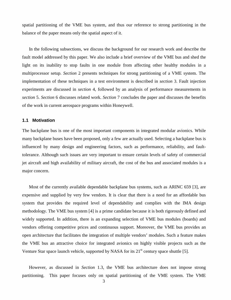
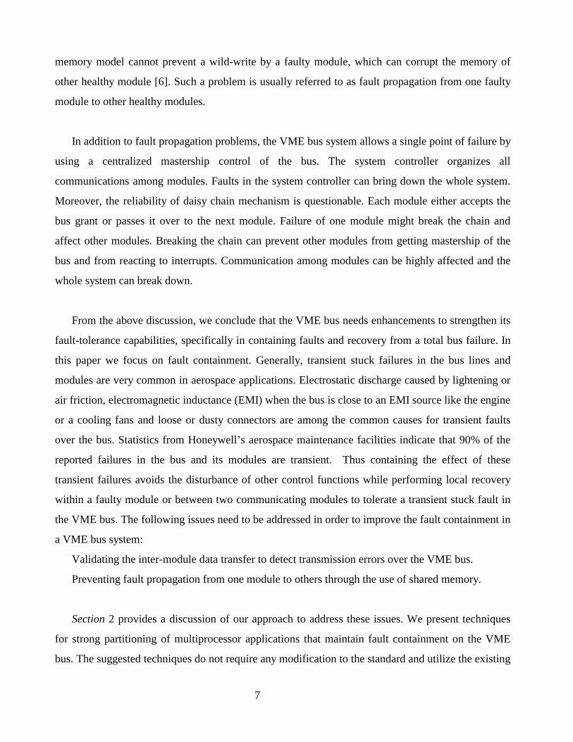
Read-Only MessageBuffer (3) Read
msg
Processor
(1) Write message
Sender Board Receiver Board
Processor
Ack
(4) Write msg ID
(5) Pollfor ack
(2) Notify
ge passing without imposing hardware changes to the bus is not easy. The main challenge is to
t the use of commonly available features of the VME system so that every module can be
ne to failures caused by erroneous behavior of other non-healthy modules.
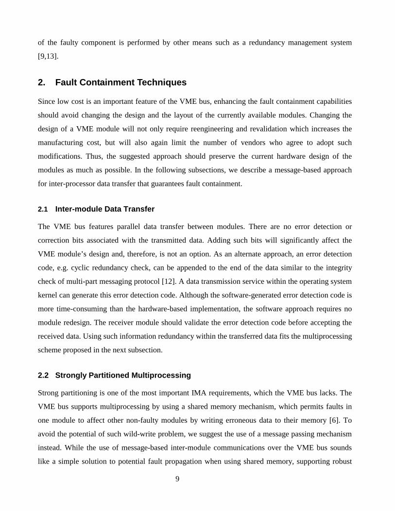
our proposed approach, each module dedicates a segment of its local memory as a buffer area
tgoing data messages and acknowledgments of incoming messages, as illustrated in fig. 3. This
is the only memory segment globally accessible to other modules. In addition, access to a
ge/ack buffer is restricted to read-only for any module that does not physically host that buffer.
nder module wants to transfer data to a receiver module, the sender writes a message into the
n message buffer and notifies the receiver. The receiver then reads that message from the
’s buffer and acknowledges it. Defining a read-only VME global address window is a very
on feature on VME modules.
Figure 3: A fault containment communication protocol
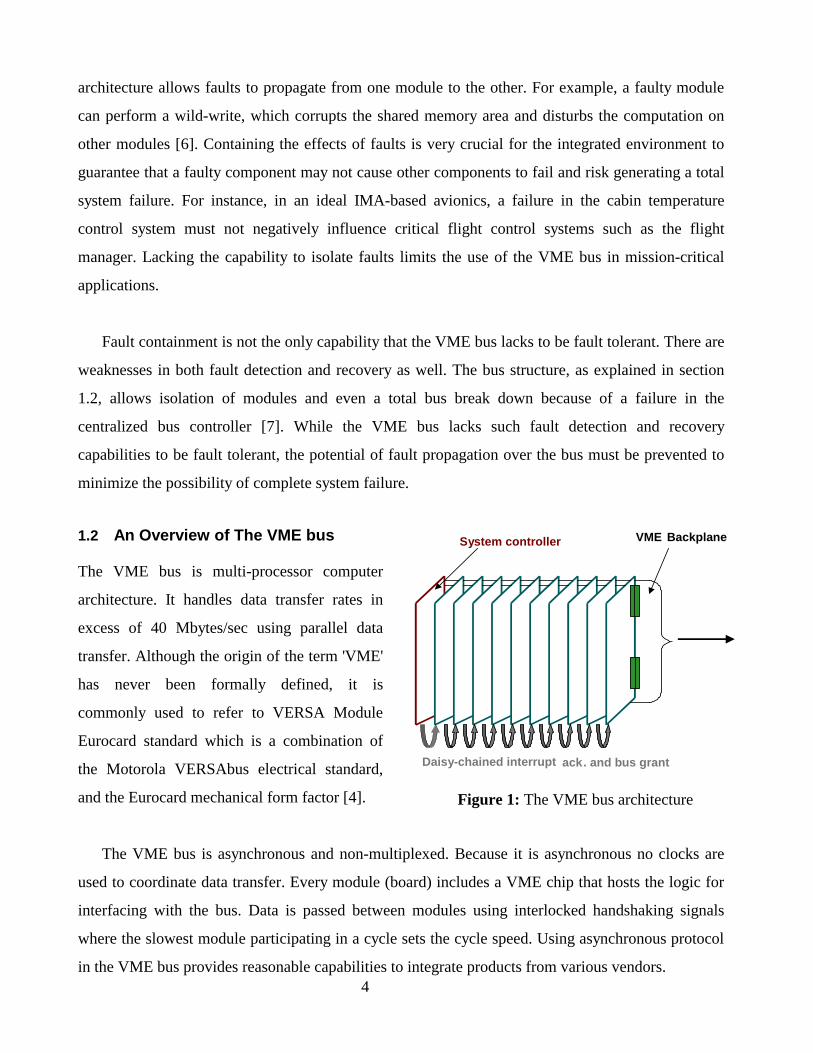
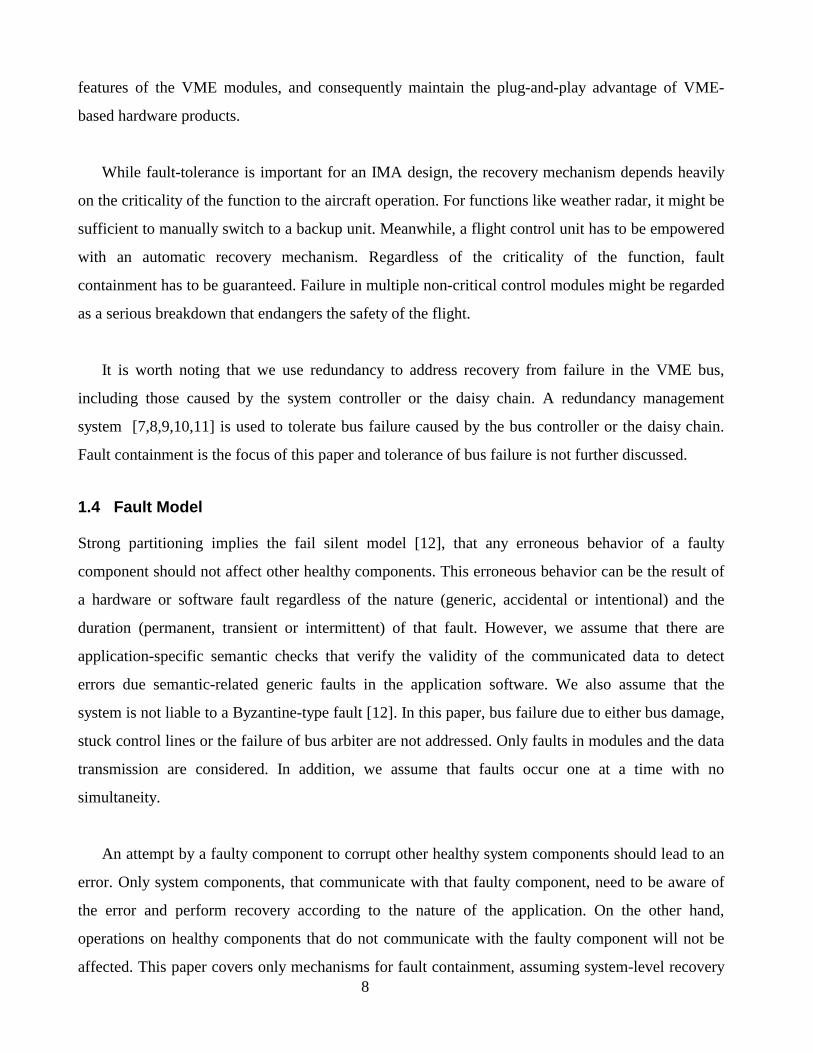
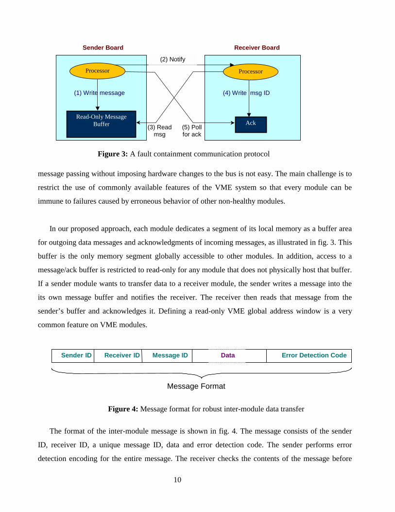
DataSender ID Receiver ID Message ID Error Detection Code
Message Format
Figure 4: Message format for robust inter-module data transfer
10
e format of the inter-module message is shown in fig. 4. The message consists of the sender
ceiver ID, a unique message ID, data and error detection code. The sender performs error
ion encoding for the entire message. The receiver checks the contents of the message before

11
accepting it. The receiver can check the sender ID and receiver ID fields to verify its retrieval of the
right message. In addition, transmission errors can be detected or recovered using the information
redundancy in the form of the error detection code in the message
Synchronization of the execution of application tasks can be achieved either; by polling the
message buffer of the sender for the required message, or by notifying the receiver by generating an
interrupt1 as soon as a message is being written by the sender in the designated address. If polling is
used, the message ID can be useful to overcome race conditions if the receiver tried to read the
message before it is ready. This may occur if the VME bus has a higher priority than the local bus.
Atomic bus cycles would not avoid such race conditions since they do not prevent local write to the
shared memory and do support only atomic write to VME memory, an operation prohibited by our
approach. The sender’s message buffer can be partitioned so that, separate buffers are dedicated to
each recipient. Receivers can expect a unique location for their messages. The adopted application
execution-synchronization mechanism is a designer’s decision.
Using such communication technique, errors in the sender can be isolated and prevented from
propagating to the receiver because no module will be granted write access to the memory of others.
Errors in the message can be either in data, sender ID, receiver ID, message ID, or message format.
The receiver should be able to detect errors in the message body by validating the message format,
the error detection code, the sender ID and the receiver ID. The message ID can be checked to
guarantee the right message sequence and to prevent race conditions. Any error in the message
detected by the receiver will invalidate the entire message and a recovery action will be taken. An
addressing fault in the receiver that may get it to read from the wrong module or the wrong address
within the right module will invalidate the message format and/or the sender ID. Furthermore, the
mapping of each module’s message buffer to the global address space of the VME system can be set
up during system configuration such that an addressing error cannot change a valid global address
1 Can be implemented by using the address-monitoring feature provided by the VME bus.

12
into another valid address. Maintaining a suitable hamming distance among buffer addresses can
guard the system against permanent or transient stuck failure of one or more address bits. Thus, the
system will be functionally partitioned. Faults remain within the faulty module and will not affect
other modules. Table 1 summarizes potential errors and the detection mechanisms.
Table 1: A summary of errors and the detection mechanisms
Error Detection Mechanism
Reading from the wrong module invalid sender ID
Reading from non-existent module VME time out
Reading the wrong message invalid message ID
Transmission error invalid error detection code
Reading wrong address, correct module invalid message format
2.3 Applicability of the Approach to VME Hardware
As we discussed earlier, enhancing the fault containment capabilities and the support for strong
functional partitioning on the VME bus should not impose significant modifications to both the
hardware manufacture and the application developer. This section presents the feasibility of the
techniques illustrated in the previous section. After conducting a market survey, we found that the
VMEchip2 [14], from Motorola, and the SVC64 [15], from Tundra, are the most commonly used
VME bus interface chips on VME modules. We studied the applicability of these techniques in VME
modules that use these interface chips.
Considering both interface chips, the strong partitioning protocol can be totally implemented in
software. In fact, it is possible to use commercial-off-the-shelf (COTS) operating systems by
extending the kernel service to include message handling. The generation and validation of the error
detection code within the message can be included in the message handler. Thus, to demonstrate the
applicability of the fault containment techniques, it is sufficient to show the feasibility of partitioning
local memory and mapping the message buffer within the VME global address space.
Both the VMEchip2 and SVC64 provide capabilities for software configurable global addressing
of the on-board memory of a module. There are software configurable map decoders that can be used
to control the global addressing of the VME modules’ local memories. A module can map a portion
13
of its local memory to the global VME bus address space rendering this portion accessible to other
modules. The hosting module can further restrict access to such portion to read-only activities. Any
attempt to violate these access restrictions will generate a bus error at the intruder module.
To prevent the possibility of other modules reading by mistake from the wrong module, these
chips allow the use of different combinations for the most significant bits for the VME address of
each module so that the hamming distance will be more than 1 bit. Thus, we can guarantee that
modules cannot read from the wrong module unless there is more than one transmission error. Given
that the number of modules is limited (maximum 22 according to the IEEE standard [4]), it is
feasible to achieve a reasonable hamming distance among the modules. Assuming, for example, that
each module allocates up to 64K byte of message buffer, which requires 16 bit addressing (out of the
32 bit address bus size), it possible to maintain a hamming distance of 8 bits among module
addresses and to isolate up to 7 simultaneous errors. Reading from a non-existing module will be
timed out by the VME bus and can be detected. Errors in the least significant 16 bits of the address
can be detected by validating the messages. Reading from a different location within the sender’s
message buffer will contain neither the right format nor the correct message semantic.
The strong partitioning protocol has been implemented and tested on modules that use the
SVC64 chip. The next section discusses the implementation and test environment in more details.
3. Implementation and Test Environment
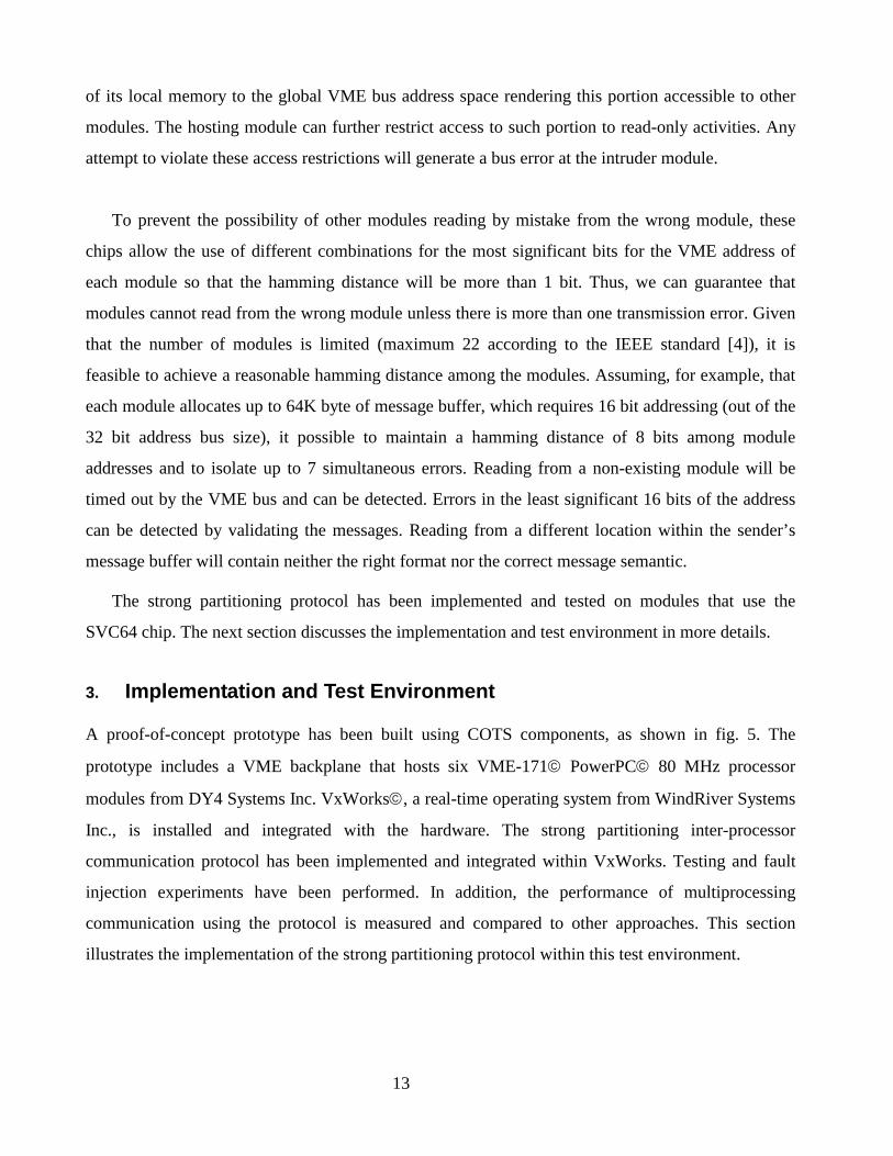
A proof-of-concept prototype has been built using COTS components, as shown in fig. 5. The
prototype includes a VME backplane that hosts six VME-171 PowerPC 80 MHz processor
modules from DY4 Systems Inc. VxWorks, a real-time operating system from WindRiver Systems
Inc., is installed and integrated with the hardware. The strong partitioning inter-processor
communication protocol has been implemented and integrated within VxWorks. Testing and fault
injection experiments have been performed. In addition, the performance of multiprocessing
communication using the protocol is measured and compared to other approaches. This section
illustrates the implementation of the strong partitioning protocol within this test environment.
Task A Task B
ITC Service
Message queue
Figure 6: Inter-task communication service
3.1
In
thr
an
ex
ser
qu
ca
co
mo
co
ba
int
mo
ac
qu
glo
bu
ou
Fi
gure 5: A proof-of-concept demonstration prototype
Software Architecture
a single processor system, one way for tasks to establish communication among each other is
ough the use of message queues. A message queue is an abstraction of a unidirectional channel,
d is typically identified by a “queue ID” or QID. Two communicating tasks use the same QID to
change messages. The delivery of the messages is handled by the Inter-Task Communication (ITC)
vice (typically part of the operating system library functions) which may maintain several message
eues depending on how many communication channels are open; see fig. 6. The ITC service takes
re of synchronizing the access to the message queue and enforcing mutual exclusion.
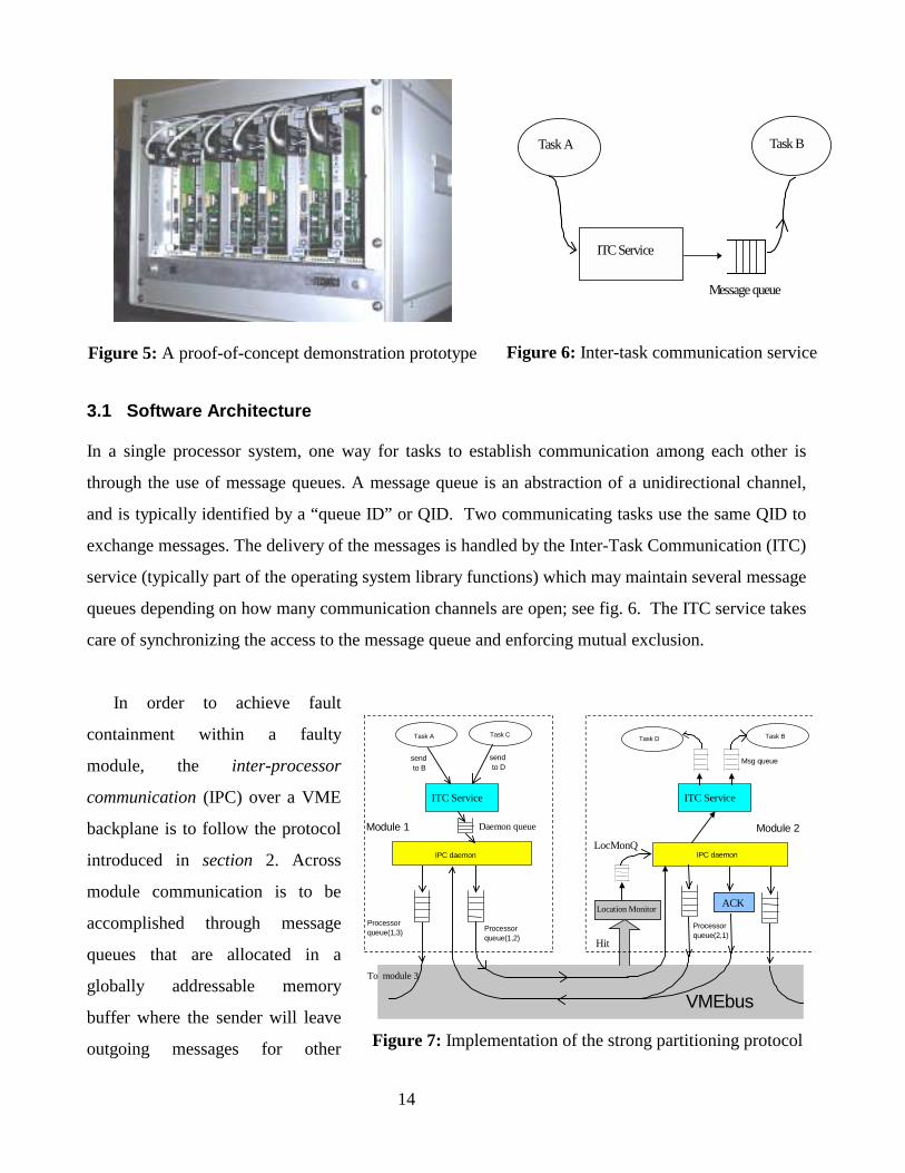
In order to achieve fault
ntainment within a faulty
dule, the inter-processor
mmunication (IPC) over a VME
ckplane is to follow the protocol
roduced in section 2. Across
dule communication is to be
complished through message
eues that are allocated in a
bally addressable memory
ffer where the sender will leave
tgoing messages for other
IPC daemon
Task A Task C
Processorqueue(1,2)
sendto B
Module 1
IPC daemon
Msg queue
Processorqueue(2,1)
sendto D
VMEbus
Task D Task B
ITC Service ITC Service
Module 2Daemon queue
Processorqueue(1,3)
To module 3
Location Monitor
Hit
LocMonQ
ACK
Figure 7: Implementation of the strong partitioning protocol
14
15
modules to read. Although a separate queue for every pair of communicating tasks can be allocated,
managing the message buffer becomes complicated if tasks are created dynamically. The message
buffer cannot be allowed to grow dynamically since there is a potential that the system runs out of
free memory space within the message buffer. Instead, queues are allocated to communicating
modules. For each (sender, receiver) permutation of modules, there is a processor queue which is
created within the global portion of the sender’s main memory to hold any messages sent to that
specific receiver by any task running on the sender module, as shown in fig. 7. Receivers have read-
only access to the message queues owned by other modules. The sizes of these queues depend on the
amount of available memory and the expected communication traffic density.
An independent task, called the IPC daemon, is created by the system at initialization to handle
inter-processor communication. The IPC daemon maintains all processor queues and performs
message sending and receiving across the VME bus. The IPC daemon can be invoked on demand
when there are requests in either the sending (daemon) or the receiving (LocMonQ) activity queue.
However, in our implementation, the IPC daemon is scheduled to run periodically to fit the real-time
nature of tasks in avionics applications [16].
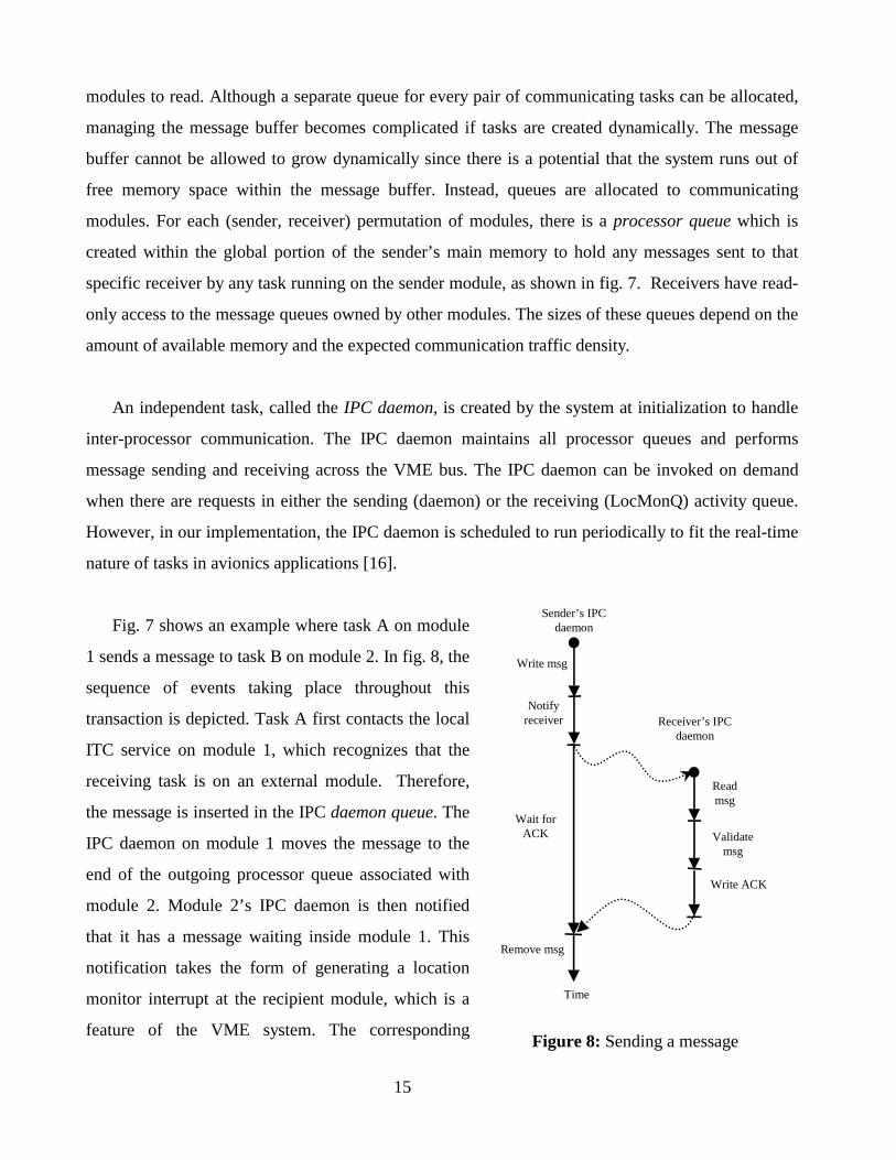
Fig. 7 shows an example where task A on module
1 sends a message to task B on module 2. In fig. 8, the
sequence of events taking place throughout this
transaction is depicted. Task A first contacts the local
ITC service on module 1, which recognizes that the
receiving task is on an external module. Therefore,
the message is inserted in the IPC daemon queue. The
IPC daemon on module 1 moves the message to the
end of the outgoing processor queue associated with
module 2. Module 2’s IPC daemon is then notified
that it has a message waiting inside module 1. This
notification takes the form of generating a location
monitor interrupt at the recipient module, which is a
feature of the VME system. The corresponding
Write msg
Sender’s IPCdaemon
Notifyreceiver
Readmsg
Validatemsg
Write ACK
Wait forACK
Remove msg
Receiver’s IPCdaemon
Time
Figure 8: Sending a message

16
interrupt service routine at the recipient module records the sender’s module ID at the end of the
LocMonQ queue for later processing by the IPC daemon. When the IPC daemon on module 2 runs, it
fetches the message from module 1 and acknowledges it by writing the message ID in an
acknowledgment cell located inside the global buffer of module 2. After the IPC daemon of module
1 reads the acknowledgement, it then deletes the message from its processor queue. Meanwhile, the
IPC daemon on module 2 delivers the message to the local ITC service, which finally stores the
message in the queue, connected to Task B2. It is worth noting that the ITC service on each processor
still handles local inter-task communication. It contacts the IPC daemon only if the target receiver is
on a different module.
The IPC daemon is scheduled to run
periodically at a frequency determined by the
system designer who takes into consideration the
traffic volume and the real-time constraints of the
communicating tasks. On each invocation, the IPC
daemon checks for all pending acknowledgments,
fetches one or more incoming messages, and sends
one or more outgoing messages, as shown in fig. 9.
Checking for all pending acknowledgements clears
the way for sending new messages as early as pos
message per invocation improves the performance by
CPU cache. The number (N) of messages to be sent
determined by the system designer as part of a con
parameters of the system. Since the IPC daemon cann
that receiver acknowledges the previous message, a ty
queue on the module, i.e. sending a message to every re
2 This is a regular message queue maintained by the operating sys
Send N messages
Check ALL pendingacknowledgements
Receive incomingmessages
Figure 9: The IPC daemon cycle
sible. Sending and receiving more than one
making use of the code that is already in the
in each execution cycle of the IPC daemon is
figuration file that contains all the operating
ot send a message to a receiver module before
pical choice of N is the number of processor
ceiver module.
tem (VxWorks in our implementation).
17
It should be noted that the handling of inter-processor communication traffic could also be
implemented as a library of service calls, which may be invoked when needed. In our application, we
found the use of an IPC daemon task convenient in scheduling the CPU and bus traffic and efficient
in performance, as explained.
3.2 Handling of Communication Failures
There are several faults that may occur during inter-processor communication. A faulty module may
send bogus notifications to other modules or stop acknowledging received messages. A faulty
module may also send a message to the wrong receiver, due to an error in determining the module ID
of that receiver. Moreover, the VME bus itself may suffer from transient and/or permanent faults on
its data and/or address lines. To handle such errors, the protocol calls for using an error detection
code as well as the validation of the sender/receiver identity fields in the header of each incoming
message. In addition, the message’s sender times out when waiting too long for an
acknowledgement.
Although the strong partitioning protocol allows the detection of erroneous behavior of a faulty
module, there is an error scenario that might have negative impact on healthy modules and need to be
carefully considered in the implementation. Such scenario happens when the location monitor
interrupts are used for message notification. A faulty sender module might continuously interrupt
other healthy modules for non-existing messages, thus overloading the IPC daemon on the recipient
modules and degrading the response time for non-faulty messages. It is worth noting that this is a
typical problem in interrupt-based notification and is not a side effect of our protocol. However in
the VME system a subtle problem might be caused when a faulty module, say module m, notifies
another module i with faulty messages disguised under the identity (address) of a module k (different
from m).
To handle the above issue, the strong partitioning protocol keeps track of two classes of
communication failures by requiring each module to maintain two error counters for each of the
other modules it communicates with, representing its own communication experience with these
modules. The first counter, snd_err_cntk, records the history of failures sending messages to
module k, whereas the second counter, rcv_err_cntk, records the history of failures receiving
18
messages from module k. Each one of these counters is to be incremented whenever the
corresponding failure occurs. On the other hand, if a one-way communication activity with a module
is completely successful3, both of its error counters are reset to zero, thus completely forgiving that
module for any failures in the past. However, if an error counter keeps increasing till it reaches a
predetermined threshold, the destiny of the corresponding communication activity is determined as
follows:
• If snd_err_cntk reaches its threshold, all send activities to module k are immediately
suspended, until further notice as explained below.
• If rcv_err_cntk reaches its threshold, an IPC-to-IPC “health-checking” message is sent to the
IPC daemon on module k indicating the imminent suspension of future receive activities unless
module k successfully acknowledges this message. If no acknowledgement is received, future
receive activities from module k are suspended. The health-checking message will only be sent
if the send activity with module k has not been suspended.
In both cases, the one-way communication is resumed only if a communication on the opposite
direction succeeds, since this will reset the error counters back to zero. The forgiveness strategy
allows the distinction between transient and permanent faults. If successful communication could be
re-established with a module, it is considered as an indication of its recovery. It is out of the scope of
this protocol to address the readmission of a faulty module once the 2-way communication with that
module has been suspended.
3.3 Integration with the Operating System
Although inter-task communication within the same VME module can use shared memory or
message passing, in the current implementation we allow only message-passing for communication
among application tasks that do not coexist on the same module. The inter-processor communication
is provided as a transparent message-passing service to application programs. Thus, a task can write
3 A send activity is completely successful only when the sent message has been acknowledged.
19
a message to the queue of another task regardless the location of the recipient. To achieve such
transparency, the library for message handling within the operating system has been replaced with
slightly different library. The new library checks for the location of the queue and invokes the
original operating system library if the target queue is local (on the same module). If the queue is
external (located on a different module), the message will be routed to the message queue of the IPC
daemon for delivery to the destination queue.
The new library refers to a system configuration table that contains, for each message queue in
the multiprocessor system, the ID of the module that hosts this queue. The application developer
prepares the system configuration table after the allocation of tasks to various modules. Each module
reads this configuration table as a part of its initialization. In avionics tasks allocation and scheduling
are always performed off-line in order to pass the FAA certification or comply with the military
validation guidelines. Thus, preparing the configuration table off-line is not imposing restrictions on
the application developer. At run time the IPC daemon uses the system configuration table to resolve
the ID of the module, on which each message queue resides, so that it inserts the message in the
proper processor queue.
In our implementation, the IPC daemon was defined as a high priority user-task. However, the
protocol can be completely integrated within the operating system by defining the IPC daemon as a
system-task and augmenting the library of system calls with the IPC library functions.
3.4 Real-Time Issues
In avionics as well as other hard real-time systems, task and resource scheduling is in the core of the
development of such systems due to the stringent timing constraints that must be satisfied. Generally,
shared resources such as the data bus have a significant role in achieving timeliness. A delayed bus
access for example might cause a task to block for an extended period and thus might miss its
deadline. Generally, issues like interrupt latency, data transfer rate and bus latency need to be
considered while scheduling the VME bus. Using the strong partitioning protocol the system
integrator needs to schedule the IPC daemon as an integral part of the task and VME bus scheduling.
Increased bus traffic might mandate invoking the IPC daemon multiple times per frame (period) to
ensure timely message delivery of inter-processor messages. In addition the overhead of the IPC
daemon has be considered in the schedulability analysis [16] to ensure timeliness under worst-case
20
scenarios. While the use of the protocol can complicate the scheduling of messages, it simplifies the
scheduling of tasks. The IPC daemon acts as a virtual task for all inter-processor communication
decreasing the coupling between tasks and bus scheduling and thus simplifying schedulability
analysis. Timeliness was not considered in our experiments and the real-time issues are not further
discussed in the paper.
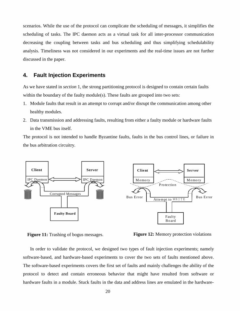
4. Fault Injection Experiments
As we have stated in section 1, the strong partitioning protocol is designed to contain certain faults
within the boundary of the faulty module(s). These faults are grouped into two sets:
1. Module faults that result in an attempt to corrupt and/or disrupt the communication among other
healthy modules.
2. Data transmission and addressing faults, resulting from either a faulty module or hardware faults
in the VME bus itself.
The protocol is not intended to handle Byzantine faults, faults in the bus control lines, or failure in
the bus arbitration circuitry.
In order to validate the protocol, we designed tw
software-based, and hardware-based experiments to
The software-based experiments covers the first set
protocol to detect and contain erroneous behavio
hardware faults in a module. Stuck faults in the data
FaultyBo ard
Attempt to WRITE
P ro tectio n
Server
M emo ry
Client
M emo ry
Bus ErrorBus Error
Figure 12: Memory protection violations
IPC Daemon
Client
IPC Daemon
Server
Faulty Board
Corrupted Messages
Figure 11: Trashing of bogus messages.
o types of fault injection experiments; namely
cover the two sets of faults mentioned above.
of faults and mainly challenges the ability of the
r that might have resulted from software or
and address lines are emulated in the hardware-
21
based experiments to verify the protocol’s ability to detect and contain errors due to permanent and
transient faults in the module bus interface or the VME bus lines themselves.
In the experiments we were keen to measure fault coverage but not latency. Since the time for
detecting most of covered faults depends on many factors such as the bus speed and usage pattern,
the module processing power, the frequency of invoking the IPC daemon, the number of open IPC
channels, message traffic, etc., measuring fault latency was not considered informative. In the
following subsections, we describe both types of experiments and discuss the results.
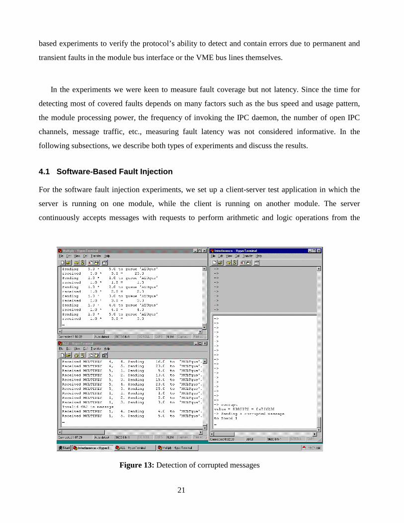
4.1 Software-Based Fault Injection
For the software fault injection experiments, we set up a client-server test application in which the
server is running on one module, while the client is running on another module. The server
continuously accepts messages with requests to perform arithmetic and logic operations from the
Figure 13: Detection of corrupted messages
22
client, and then sends back messages containing the results. All communication activities between
the server and the client follow the strong partitioning protocol. A third module (fault injector) has
been designated to run an erroneous application whose behavior interferes with the server and the
client.
The fault injector module randomly shows one of three types of erroneous behavior. First, the
faulty (fault injector) module would attempt to disrupt the client-server communication by sending
bogus messages (fig. 11). Second, the faulty module would attempt to corrupt the client and/or the
server by sending real messages with invalid data in them. This simulates either a faulty behavior in
the IPC daemon of some modules, or even a transmission error on the VME bus due to permanent
and/or transient electrical faults on the data lines. Finally, the faulty module would attempt to write
to the memory of the two healthy modules (fig. 12).
A total of 2000 fault injection experiments were performed. In each experiment, the fault injector
triggers one of the three mentioned erroneous scenarios. The selection of the injected fault type per
experiment as well as the time intervals between successive experiments was random using uniform
and exponential distributions, respectively. The healthy modules are set to log errors in inter-
processor messages and their error counter thresholds were set to a very large number to allow
experiments to run before shutting down communication with the fault injector module. Other than
memory protection violations made by the fault module, in all cases the client and server modules
were able to detect and prevent the intrusion attempt by the faulty module. Memory protection
violations impact only the fault injector module and therefore were not reported by the healthy
modules. Considering fault containment as a goal, we could achieve 100% coverage, although only
about 2/3 of injected faults could be detected by one of the communicating modules.
Fig. 13 shows a screen capture of the second experiment. While the client and server are
communicating, the faulty module sends a formatted (but corrupted) message to the server. The
server detects the receipt of a corrupted message by validating the error detection code (CRC), logs
such an error and displays the error message “Invalid CRC in message”.

23
4.2 Hardware-Based Fault Injection
Next, we configured the system to test the effect o
lines of the VME bus. We set up three modules s
requests to one of its neighbors, and, in the mean
coming from the other neighbor, as illustrated in fi
The most significant 8 bits of the 32-bit addr
ID, while the least-significant 24 bits represent a lo
hamming distance of 2 is maintained among the
modules’ message buffers.
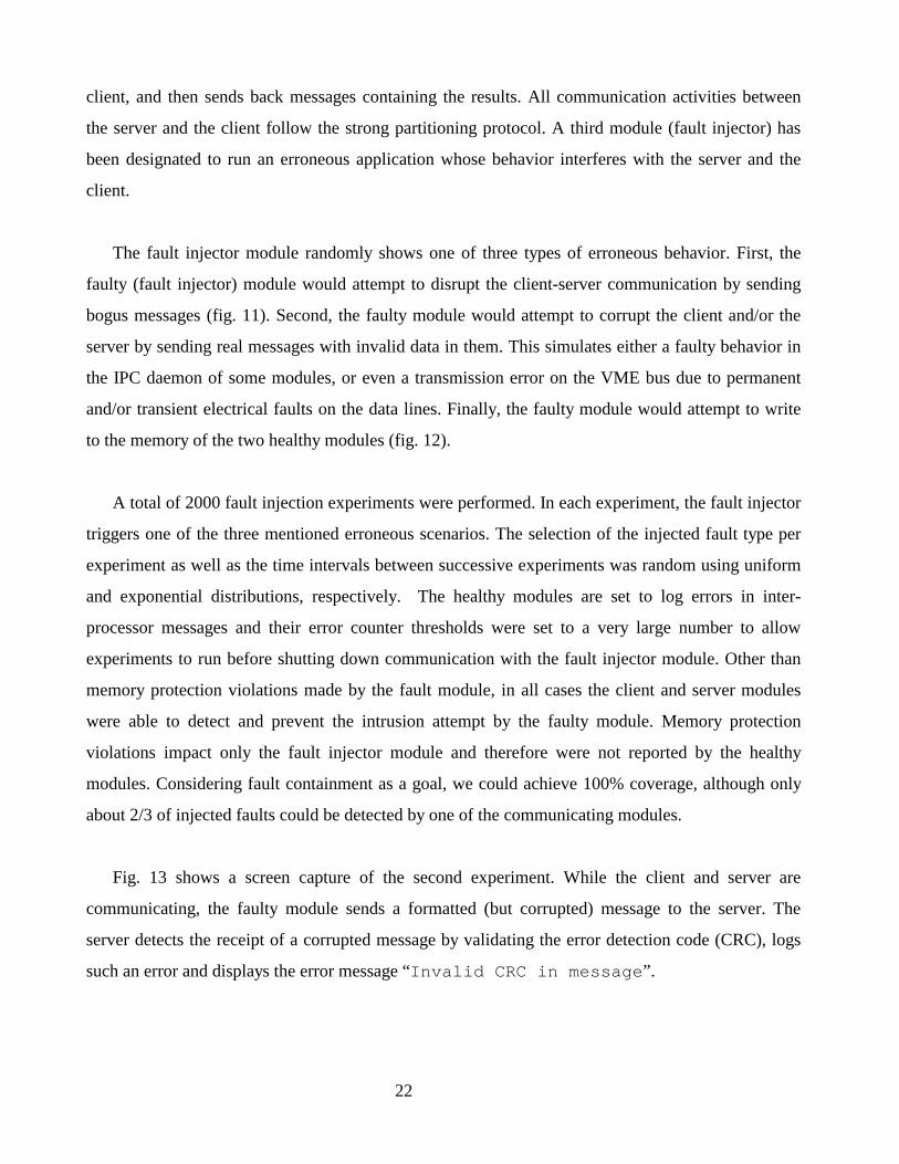
One of the modules was attached to the VME
allowing us to forcibly change any of the VME bu
signals, as shown in fig. 15. For each of the tested
card for injecting hardware faults:
1. On the module side: Injecting faults on this
emulates what happens when the module is dri
the backplane are non-faulty.
2. On the bus side: This emulates faults in the b
system.
Client 0
Server 0
Clien
Serve
Module 0 Modu
Figure 14: Communication set-
Client 2
Server 2
t 1
r 1
Module 2le 1
up for hardware fault injection
f hardware faults in any of the data or the address
o that each one hosts a client application sending
time, also hosts a server application for requests
g. 14.
ess have been designated to represent the module
cal address inside the selected module. A minimal
modules while configuring the VME addresses
bus via an extender card that contained jumpers
s signal lines such as the data, address, or control
bus lines, there were two locations on the extender
side represents failure only in the module. This
ving the bus with a faulty signal while the lines on
us lines themselves and affects all modules in the
24
We started with module 1 and injected stuck-at-one (+5v) and stuck-at-zero (GND) errors on
each data and address line. The experiments were later repeated for each of the other two modules,
one module at a time. For every pin we repeated the fault injection three times per stuck fault type.
Two out of these three repetitions emulated transient faults, for which the stuck fault were removed
quickly, while in the third one the stuck fault was left for a longer period to emulate permanent
faults. The error counter thresholds were set to a small number to allow capturing the effect of
permanent fault without unreasonably extending the experiment time.
In the following subsections, we describe experiments’ outcome when faults were injected on the
address lines and then on the data lines of module 1. The section is concluded with a summary of the
results of the hardware-based fault injection experiments. As we mentioned at the beginning of this
section, no control lines were corrupted. Failure of bus control circuitry is considered a total system-
wide communication failure that cannot be contained by applying the strong partitioning protocol.
Other research work [8] has addressed tolerating these kinds of failures through redundancy.
4.2.1 Hardware Fault Injection on Address Lines
When errors were injected on the address lines of the module side of the extender board,
communication between module 0 and 2 was not affected. In fact, there was a situation where
communication with module 1 itself was not disrupted. When injecting faults in the module ID
portion of the address lines, the observed results depended on the relationship between the stuck
value of bit and the bit’s value in the module ID.
Bus Extender Board
Figure 15: Hardware-based fault injection setup

25
• Value of stuck bit = the bit value in the ID of module 1
When the value of the corresponding bit in the ID of module 0 and/or module 2 has the same
value of the stuck bit, communication with module 1 continues without a problem. On the
other hand, if the value is different from the stuck bit, module 1 could not access module 0
and/or module 2 although it continued to be accessible to them. Module 1 reported errors while
notifying or reading messages from such module(s). The communicating module(s) reported
errors too while looking for acknowledgement from module 1. Since module 1 became unable
to access the message buffer of module 0 and/or module 2, it could not read messages sent by
either or both of them and thus did not acknowledge.
• Value of stuck bit ≠ the bit value in the ID of module 1
Module 1 became inaccessible to both modules 0 and 2. Modules 0 and 2 reported bus errors
during notifying module 1 of a message, reading a message and looking for acknowledgement
from module 1 since the VME bus circuitry considered this as an attempt to access a non-
existing module.
When faults were injected on the least significant 24 bits of the module side, one of the following
errors occurred:
a) Message notifications going out of module 1 missed their target. Module 1 timed out waiting for
an acknowledgement to arrive from another module that never got the notification in the first
place.
b) An attempt to access a non-existing memory region was made. Module 1 received a memory
protection violation error.
c) A message with the wrong format was fetched. Module 1 identified the received message as
invalid and completely ignored it.
d) A properly formatted message intended for a different receiver was fetched. Module 1 recognized
the received message as invalid and ignored it.
When the address lines were corrupted on the bus side, the three modules had a bus error most of
the time. If the corrupted address line was a part of the module ID portion of the address, there were
some cases in which the system continued without a failure or with a partial failure. When an address
26
line was stuck on a value that was consistent with the ID of two or more modules, communication
between these modules continued. For example, when we assigned the modules ID to be F0, 80 and
60 for modules 0,1 and 2 respectively, and injected a stuck at 1 error on the most significant address
line, communication between the first and second modules was not affected. Corruption of any the
least significant 24 address bits consistently led to a bus error on all modules.
4.2.2 Hardware Fault Injection on Data Lines
Next, we injected errors in the data lines. We enforced stuck-at-1 and stuck-at-0 faults on each data
line, one at a time. When injecting the fault at the bus side of the extender card, all the three modules
encountered a CRC validation error. In the case of injecting the fault at the module side, all messages
involving module 1 were rejected as they failed to pass the CRC validation at the receiving module.
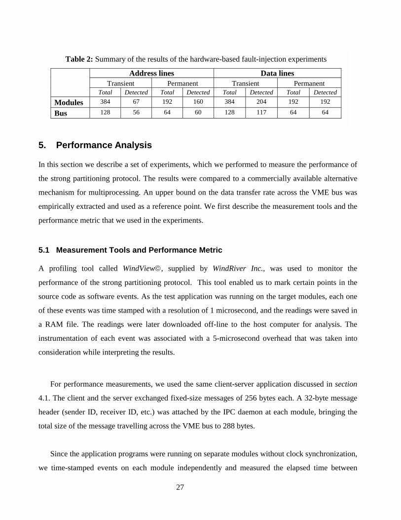
4.2.3 Summary of Experiments’ Results
We ran 3 experiments per line per type of stuck faults. Therefore for each module a total of 384 fault
injection experiments were conducted to cover the 64 data and address interface lines to the VME
bus (64 lines × 3 experiments × 2 types). Similarly a total of 384 experiments involved the physical
bus address and data lines. Considering the bus and all three modules, a total of 1456 experiments
were conducted using the described setup, of which 1/3 were permanent and 2/3 were transient
faults. In all fault-injection experiments that we conducted, communication between the two healthy
modules was never interrupted unless we injected a fault on the bus side. The system recovered from
all transient faults. Fault coverage from fault containment point-of-view was 100%. However not all
faults were detected. Only 35% of transient faults injected at the module’s bus interface were
detected, while 68% of transient bus errors were detected. Given the extensive message traffic
included in the experiment setup, 91% of transient faults injected on the data lines of the bus and
53% of stuck faults on the data lines of the module interface to the bus were detected. Less detection
rate were observed for transient faults on address lines since only a subset of the VME address space
is used by the three modules in our experiment. Most of permanent faults were detected. Some of the
permanent faults injected on address lines went undetected because they affected lines that are
always zero or one. Validation of the CRC appended to the IPC messages constantly detected
permanent stuck faults on the data bus. Detailed results are shown in table 2.
5. P
In this s
the stro
mechan
empiric
perform
5.1 M
A prof
perform
source
of these
a RAM
instrum
conside
For
4.1. Th
header
total siz
Sinc
we tim
MBu
Table 2: Summary of the results of the hardware-based fault-injection experiments
Address lines Data lines
27
erformance Analysis
ection we describe a set of experiments, which we performed to measure the performance of
ng partitioning protocol. The results were compared to a commercially available alternative
ism for multiprocessing. An upper bound on the data transfer rate across the VME bus was
ally extracted and used as a reference point. We first describe the measurement tools and the
ance metric that we used in the experiments.
easurement Tools and Performance Metric
iling tool called WindView, supplied by WindRiver Inc., was used to monitor the
ance of the strong partitioning protocol. This tool enabled us to mark certain points in the
code as software events. As the test application was running on the target modules, each one
events was time stamped with a resolution of 1 microsecond, and the readings were saved in
file. The readings were later downloaded off-line to the host computer for analysis. The
entation of each event was associated with a 5-microsecond overhead that was taken into
ration while interpreting the results.
performance measurements, we used the same client-server application discussed in section
e client and the server exchanged fixed-size messages of 256 bytes each. A 32-byte message
(sender ID, receiver ID, etc.) was attached by the IPC daemon at each module, bringing the
e of the message travelling across the VME bus to 288 bytes.
e the application programs were running on separate modules without clock synchronization,
e-stamped events on each module independently and measured the elapsed time between
Transient Permanent Transient PermanentTotal Detected Total Detected Total Detected Total Detected
odules 384 67 192 160 384 204 192 192
s 128 56 64 60 128 117 64 64

28
events. Since both the server and client programs were running on exactly similar modules, we did
not expect a need to perform any calibration for the speed of the processors. However, a test was
performed using a logic analyzer to ensure that. The test involves executing a small program that
generates a bus request periodically in a loop and measuring the time between successive requests
through connecting the bus request line to the logic analyzer. The test experiment was repeated for
the modules involved and similar timing results were observed, confirming that no calibration is
necessary.
5.2 Maximum Measurable Transfer Rate over the VME bus
In order to obtain an upper bound on the most efficient data transfer rate across the VME bus, we
measured the time required for an assembly language routine to perform a memory write of 256
bytes from one module to the other. The time for writing 256 bytes was measured using a logic
analyzer and found to be 144 microseconds. This experiment provided us with an upper bound for
the bus transfer rate, and was later used to validate the accuracy of the measurements obtained using
WindView. It should be noted that this upper bound could be only achieved using optimized
assembly code.
5.3 Measurement for the Strong Partitioning Protocol
We next measured the end-to-end delivery time of the 256 bytes data, including the message header,
when the strong partitioning protocol was applied. We recorded 50 different readings for the send
and receive phases of the message delivery. Table 3 shows the average of these 50 readings. It should
be noted that the reported time for message validation includes the consumed time for checking the
message header and verifying the CRC code. The time for putting the message in the processor
queue includes the time for forming the message header and appending the CRC code. The average
end-to-end delivery time was found to be 302.3 microseconds ( send 92.4 + receive 209.9 ). It should
be noted that the actual data transfer across the VME bus is performed during the receive phase.
During the experiment we observed significant variance in the timing of first execution of the
IPC daemon and in message-handling library of VxWorks. Analysis of the timing behavior of the
IPC daemon pointed out the dominant contribution of a cache miss to the increased execution time of
first invocation of the IPC daemon. Excluding the reading related to the first time execution of the

29
IPC daemon led to a very negligible variance. This conclusion was further validated by repeating the
experiment while disabling the instruction cache of the PowerPC processor. The variability of the
message-handling library of VxWorks was persistent and could only be minimized by disabling the
cache. With that analysis of the variance the 50 readings were considered sufficient.
Table 3: Performance measurements for the partitioning protocol
Action Description Duration in µµµµsec Receive One Message
Handle location monitor interrupt 37.6 Fetch message across the VME bus 170.0 Validate and acknowledge message 2.3
Total for receive 209.9 Send One Message
Get message from daemon queue 49.1 Put message in processor queue 42.1 Notify receiver 1.2
Total for Send 92.4
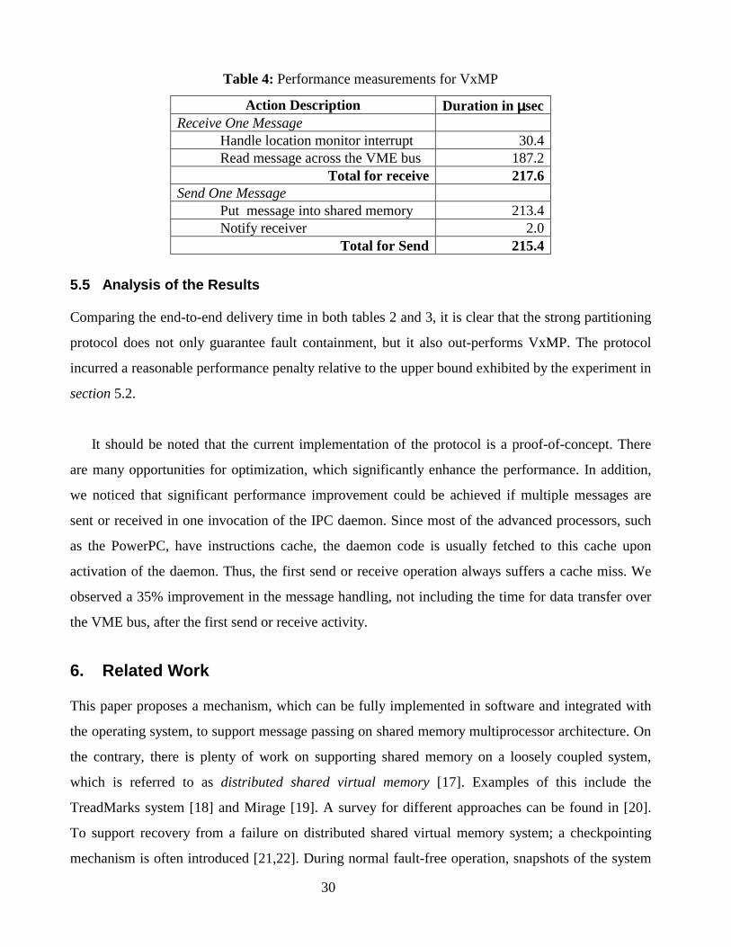
5.4 Measurement for VxMP Shared Memory Protocol
In this experiment, we measured the performance of the shared memory approach applied by
VxMP, which is a multiprocessor extension of the VxWorks operating system. VxMP provides
an abstraction of shared memory so that applications can refer to the shared object by name. VxMP
only resolves the addresses for the programmer without maintaining mutual exclusion for accessing
the shared memory relying on hardware support for that. Obviously VxMP provides only shared
memory management without fault containment. It should be noted that VxMP requires the shared
memory to be physically located on a separate module by itself. Thus transferring data between
modules usually requires two bus transmissions; first the sender writes to the shared memory, next
the receiver reads that data from the shared memory.
The client-server application has been rewritten using VxMP to exchange 256-byte. Table 4
shows the performance results for sharing 256 bytes data. The end-to-end time for sending 256 byte
using VxMP is 433 µ sec (217.6 + 215.4).
30
Table 4: Performance measurements for VxMP
Action Description Duration in µµµµsec Receive One Message
Handle location monitor interrupt 30.4 Read message across the VME bus 187.2
Total for receive 217.6 Send One Message
Put message into shared memory 213.4 Notify receiver 2.0
Total for Send 215.4
5.5 Analysis of the Results
Comparing the end-to-end delivery time in both tables 2 and 3, it is clear that the strong partitioning
protocol does not only guarantee fault containment, but it also out-performs VxMP. The protocol
incurred a reasonable performance penalty relative to the upper bound exhibited by the experiment in
section 5.2.
It should be noted that the current implementation of the protocol is a proof-of-concept. There
are many opportunities for optimization, which significantly enhance the performance. In addition,
we noticed that significant performance improvement could be achieved if multiple messages are
sent or received in one invocation of the IPC daemon. Since most of the advanced processors, such
as the PowerPC, have instructions cache, the daemon code is usually fetched to this cache upon
activation of the daemon. Thus, the first send or receive operation always suffers a cache miss. We
observed a 35% improvement in the message handling, not including the time for data transfer over
the VME bus, after the first send or receive activity.
6. Related Work
This paper proposes a mechanism, which can be fully implemented in software and integrated with
the operating system, to support message passing on shared memory multiprocessor architecture. On
the contrary, there is plenty of work on supporting shared memory on a loosely coupled system,
which is referred to as distributed shared virtual memory [17]. Examples of this include the
TreadMarks system [18] and Mirage [19]. A survey for different approaches can be found in [20].
To support recovery from a failure on distributed shared virtual memory system; a checkpointing
mechanism is often introduced [21,22]. During normal fault-free operation, snapshots of the system
31
state (registers and memory contents) are stored in a repository to assist the applications recover from
a failure. The reader is referred [23] to for a survey of various recovery techniques and strategies.
Achieving fault containment in shared memory multiprocessor systems has been the subject of
intense study at the Computer System laboratory at Stanford for the FLASH multiprocessor
architecture [6,13,24]. The approach taken is to partition the multiprocessors into cells. Every cell
controls a portion of the hardware and shared resources. A cell may include one or multiple
processors. Each cell runs an independent multiprocessor operating system. A hardware solution has
been suggested to protect a cell from a wild-write by any faulty cell. The operating system
continuously runs across-cell checks for failure detection and a distributed recovery routine needs to
be executed upon the detection of a fault. Our approach is different in that we rely on the memory
management capabilities of the VME bus interface chip to protect modules from wild-write, since we
cannot introduce any hardware change. We prevent across-module writing and consequently restrict
inter-processor communication only to massage passing and do not support memory sharing.
However, we do not see that as a drawback since virtual memory is usually not recommended in
mission critical real-time applications due to its negative impact on system predictability [16]. In
addition, our fault detection is quite simple. We rely on timing out messages, a feature, which is built
in the VME bus interface logic. Furthermore, the strong partitioning protocol, presented above, is
easy to implement and integrate with COTS single processor operating systems.
Fault containment has been addressed by design in [10,25,26,27]. In the MAFT architecture [10]
and MARS [27], fault containment is channel-based. A channel includes a processor, memory and
redundancy management module. Communication among channels is message based. Across
channel voting and synchronization are used to detect, isolate and tolerate faults in any of the
channels. On the other hand, the software implemented fault tolerant (SIFT) architecture allows the
use of shared memory for inter-processor communication [26]. The SIFT approach calls for the use
of a tailored data bus that allows a processor to read and write to its own memory while giving it
read-only access to other memories. In our case the VME data bus could not be altered and
techniques to enforce memory partitioning had to be developed. In [25] a dedicated dual port
memory is included for the exclusive use of each pair of processors to communicate with each other.
The memory is empowered with error detection/correction code to detect stuck failures. Recovery of
permanent faults in memory is performed by making the affected pair of processors to communicate
32
through a third processor. Again, in our case supporting strict spatial partitioning while allowing
inter-procssor communication has to be implemented without changing the VME standard.
A different definition of fault containment from ours has been used in [28,29]. Containing faults
meant minimizing rather than eliminating the effect of a component failure on other healthy
components. The work mainly accelerates failure recovery using self-stabilization protocols, which
are algorithm-based approach to achieving fault-tolerance. The technique is to minimize the number
of components affected by a faulty component so that the self-stabilization protocol not only
guarantees convergence to a recovery but also expedites that recovery and thus limiting the impact of
the failure on the system.
7. Conclusion
While achieving fault containment in systems designed from scratch has been shown in the literature,
COTS systems bring a unique challenge since they are usually developed without considering fault
containment as a requirement. Therefore, any approach to preventing fault propagation from a faulty
module to healthy module in a COTS system, such as the VME, is constrained by its present design
that could not be changed. In this paper, it has been shown that the VME bus can be strongly
partitioned without imposing changes to the VME hardware. A multiprocessor message passing
communication protocol has been presented. The message passing protocol provides fault
containment over the bus. Messages can be verified with respect to sender and receiver IDs as well
as the message ID. In addition, information redundancy in the form of error detection code can be
provided within the message to verify data transmission over the bus.
The strong partitioning protocol has been implemented in software without imposing any
hardware modifications. A proof-of-concept prototype has been built, in which the strong
partitioning protocol has been integrated with COTS real-time operating system. The protocol has
been added as an operating system service, which is transparent to programmers. The fault injection
experiments demonstrated the efficiency of the approach in fault containment.
Although the increased data transfer due to message overhead and information redundancy will
affect the performance of the VME bus, it has been shown that the burden on the bus bandwidth is
33
limited. Clearly the longer the data size within the message, the more efficient the strong partitioning
protocol.
The technology presented in this paper is crucial for many dependable multiprocessor space and
avionics programs. For instance, at Honeywell, the technology has been applied to the vehicle
management computer (VMC) for an unmanned space shuttle. The VMC integrates multiple mission
critical control modules such as mission manager, flight control and vehicle subsystems manager
with other less critical modules within a VME cabinet. It is extremely important to contain any fault
within the faulty module and protect other modules in the system. The integration of utility control
system is another project that benefits from this technology. The goal is to integrate multiple utility
control units, which are currently federated on the aircraft, into one cabinet. Utility controls such as
electric power system, cabinet pressure and bleed air system are regarded as medium-criticality
control functions on the aircraft. However, integrating multiple utility control modules makes the
integrated unit highly critical since it may affect the safety of the flight. The strong partitioning
protocol is to be used for handling inter-module communication to prevent fault propagation and
protect the system from a complete failure when one module fails.
Acknowledgement
Thanks are due to Billy He, Eric Burton, Tim Steele and Chris Dailey for their help in the
implementation. The authors are also indebted to Dr. Yang-Hang Lee, Dr. Dar-Tzeng Peng and
members of the reliable systems group at Honeywell for their constructive critiques. A shorter
version of this paper appeared in the proceedings of the 1998 IEEE Fault Tolerant Computing
Symposium.
References
[1] Design guide for integrated modular avionics: ARINC report 651 (Annapolis, MD: Aeronautical Radio Inc., 1991).
[2] J. Rushby, Partitioning in avionics architecture: requirements, mechanisms and assurance,
Technical Report CR-1999-209347, NASA, 1999. [3] Backplane data bus: ARINC specification 659 (Annapolis, MD: Aeronautical Radio Inc.,
1993).

34
[4] IEEE standard for a versatile backplane bus: VME bus std 1014-1987 (New York, NY: The Institute of Electrical and Electronics Engineers, 1988).
[5] J. Keller, Avionics innovation marks new space shuttle, Military & Aerospace Electronics,
8(4), 1997, 1-7. [6] J. Chapin, et al., Hive: Fault containment for shared-memory multiprocessors, Proc. 15th ACM
Symposium on Operating Systems Principles (SOSP-15), 1995,15-25. [7] M. Younis and J. Zhou, A VME-based fault tolerant architecture, Technical Report, Honeywell
International, Inc., 1997. [8] O. Sokolsky, M. Younis, H.H. Kwak, I. Lee, & J. Zhou, Verification of the redundancy
management system for space launch vehicle: a case study, Proc. 4th IEEE Real-Time Technology and Applications Symposium (RTAS’98), Denver, Colorado, 1998, 220-229.
[9] R. Kieckhafer, C. Walter, A. Finn, & P. Thambidurai, The MAFT architecture for distributed
fault tolerance, IEEE Transactions on Computers, 1988, 398-405. [10] P. Thambidurai, A.M. Finn, R.M. Kieckhafer, & C.J. Walter, Clock synchronization in MAFT,
Proc. IEEE 19th International Symposium on Fault-Tolerant Computing, 1989,142-149. [11] J. Zhou, "Design capture for system dependability," Proc. of Complex Systems Engineering
Synthesis and Assessment Workshop, Silver Spring, Maryland, 1992, 107-119. [12] D. Pradhan, Fault-tolerant computer system design (Englewood Cliffs, NJ: Prentice-Hall,
1996). [13] M. Rosenblum, et al., Implementing efficient fault containment for multiprocessors: confining
faults in a shared-memory multiprocessor environment, Communications of the ACM, 39(9), 1996, 52-61.
[14] Motorola MVME162LX embedded controller programmer's reference guide, (Tempe, AZ:
Motorola, Inc., 1993). [15] Tundra Universe SCV64 Trooper II VME bus interface component manual (Ontario, Canada:
Tundra, 1996). [16] W. Halang & A. Stoyenko, Constructing predictable real-time systems (Boston-Dordrecht-
London: Kluwer Academic Publishers, 1991). [17] K. Li & P. Hudak, Memory coherence in shared virtual memory systems, ACM Transactions
on computer Systems, 7(11), 1989, 321-357. [18] C. Amza, et al. TreadMarks: Shared memory computing on networks of workstations, IEEE
Computer, 29(2), pp. 18-28, February 1996.
35
[19] B. Fleisch, & G. Popek, Mirage: A coherent distributed shared memory design, Proc. of the 12th ACM Symposium on Operating Systems Principles, published in Operating Systems Review 23(5) Special Issue, 1989, 211-223.
[20] M. Stumm and S. Zhou, “Algorithms implementing distributed shared memory”, IEEE
Computer, 23(5), 1990, 54-64. [21] B. Fleisch, “Reliable distributed shared memory”, Proc. 2nd Workshop on Experimental
Distributed Systems, 1990, 102-105. [22] M. Stumm, & S. Zhou, Fault tolerant distributed shared memory algorithms, Proc. 2nd IEEE
Symposium on Parallel and Distributed Processing, 1990, 719-724. [23] C. Morin & L. Puaut, A Survey of recoverable distribute shared virtual memory systems, IEEE
Transactions on Parallel and Distributed Systems, 8(9), 1997, 959-969. [24] D. Teodosiu, et al., Hardware fault containment in scalable shared-memory multiprocessors,
Proc. 24th ACM International Symposium on Computer Architecture (ISCA-24), 1997, 73-84. [25] G. Khan, “Fault-tolerant architecture for high performance embedded system applications”,
Proc. IEEE Conference on Computer Design: VLSI in Computers & Processors, Austin, Texas, 1998, 384-389.
[26] J. Wensley, et. al., SIFT: Design and analysis of a fault-tolerant computer for aircraft control,
Proceedings of the IEEE, 66(10), 1978,1240-1255. [27] H. Kopetz, et. al. Distributed fault-tolerant real-time systems: the MARS approach, IEEE
Micro, 9(1), 1989, 25-40. [28] S Ghosh, A Gupta, T Herman, & SV Pemmaraju, Fault-containing self-stabilizing algorithms,
Proc. 5th Annual ACM Symposium on Principles of Distributed Computing (PODC96), 1996, 45-54.
[29] S Ghosh, & SV Pemmaraju, Tradeoffs in fault-containing self-stabilization, Proc. 3rd
Workshop on Self-Stabilizing Systems, 1997, 157-169. Biography
Mohamed F. Younis received B.S. degree in computer science and M.S. in engineering mathematics
from Alexandria University in Egypt in 1987 and 1992, respectively. In 1996, he received his Ph.D.
in computer science from New Jersey Institute of Technology.
36
Dr. Younis is currently a research scientist with the Honeywell Advanced Systems Technology
Group, where he is leading multiple projects on architectural support for integrated modular
avionics, addressing issues related to fault-tolerant and real-time computing and software integration
in distributed processing environment. He participated in developing the Redundancy Management
System for the Vehicle and Mission Computer of NASA’s X-33 space launch vehicle. Dr. Younis’
technical achievements at Honeywell are widely recognized within and outside the company. His
technical interests include fault tolerant computing, system integration, distributed real-time and
complex systems and compile-time analysis. Dr. Younis has served different committees and has
numerous publications in his research field.
Mohamed Aboutabl