techniques for improving the scalability of data center
TRANSCRIPT

Purdue UniversityPurdue e-Pubs
Open Access Dissertations Theses and Dissertations
Fall 2014
Techniques for improving the scalability of datacenter networksAdvait DixitPurdue University
Follow this and additional works at: https://docs.lib.purdue.edu/open_access_dissertations
Part of the Computer Sciences Commons
This document has been made available through Purdue e-Pubs, a service of the Purdue University Libraries. Please contact [email protected] foradditional information.
Recommended CitationDixit, Advait, "Techniques for improving the scalability of data center networks" (2014). Open Access Dissertations. 260.https://docs.lib.purdue.edu/open_access_dissertations/260

Graduate School ETD Form 9 (Revised 01/14)
PURDUE UNIVERSITY GRADUATE SCHOOL
Thesis/Dissertation Acceptance
This is to certify that the thesis/dissertation prepared
By
Entitled
For the degree of
Is approved by the final examining committee:
To the best of my knowledge and as understood by the student in the Thesis/Dissertation Agreement.Publication Delay, and Certification/Disclaimer (Graduate School Form 32), this thesis/dissertationadheres to the provisions of Purdue University’s “Policy on Integrity in Research” and the use of copyrighted material.
Approved by Major Professor(s): ____________________________________
____________________________________
Approved by:
Head of the Department Graduate Program Date
Advait Abhay Dixit
Techniques for Improving the Scalability of Data Center Networks
Doctor of Philosophy
Ramana Rao Kompella
Y. Charlie Hu
Patrick Eugster
Sonia Fahmy
Y. Charlie Hu
Ramana Rao Kompella
Sunil Prabhakar, William J. Gorman 11/04/2014


TECHNIQUES FOR IMPROVING THE SCALABILITY
OF DATA CENTER NETWORKS
A Dissertation
Submitted to the Faculty
of
Purdue University
by
Advait Abhay Dixit
In Partial Fulfillment of the
Requirements for the Degree
of
Doctor of Philosophy
December 2014
Purdue University
West Lafayette, Indiana

ii
To my parents.

iii
ACKNOWLEDGMENTS
I would like to thank my advisors Professor Ramana Rao Kompella and Professor
Y. Charlie Hu for their guidance and support throughout my PhD. They helped me
get started with my PhD, patiently guided my research and kept me motivated in
di�cult times. I will forever be indebted to them.
I would like express my gratitude to Dr. Fang Hao, Dr. Sarit Mukherjee and
Dr. T. V. Lakshman, all from Bell Labs, for introducing me to software-defined
networking. The project that started during my internship there evolved into ElastiCon
which is incorporated in this dissertation.
Professor Patrick Eugster and Dr. Kirill Kogan have helped me immensely during
my last year at Purdue University. They helped guide my research in a new direction
and provided the basic idea behind composing SDN controllers, which I have included
in this dissertation.
I am grateful to Dr. Nandita Dukkipati who mentored me during my internship
at Google. The experience of working in a real data center environment has been
of great help. I also want to thank Nipun Arora, my mentor during my internship
at NEC Labs. The internship helped me understand the complexities involved in a
deploying a software-defined network.
I also want to thank Dr. Rick Kenell and Dr. Je↵ Turkstra for helping me get
started when I first arrived at Purdue. My thanks also go to labmates Dr. Myungjin
Lee, Dr. Pawan Prakash and Hitesh Khandelwal. The technical discussions and light-
hearted conversations in the corridors of Lawson building made my time in the lab
more productive and enjoyable.
I owe my greatest gratitude to my parents, Rita and Abhay Dixit, and my sister
and brother-in-law, Ruhi and Harsha Joshi, for encouraging me to return to academia
for a PhD and supporting me for the entire journey. Last, but not the least, I thank

iv
my wife Praveena Kunaparaju. Your love and companionship have given me strength
to face the challenges of graduate student life.

v
TABLE OF CONTENTS
Page
LIST OF TABLES . . . . . . . . . . . . . . . . . . . . . . . . . . . . . . . . vii
LIST OF FIGURES . . . . . . . . . . . . . . . . . . . . . . . . . . . . . . . viii
ABBREVIATIONS . . . . . . . . . . . . . . . . . . . . . . . . . . . . . . . . x
ABSTRACT . . . . . . . . . . . . . . . . . . . . . . . . . . . . . . . . . . . xi
1 INTRODUCTION . . . . . . . . . . . . . . . . . . . . . . . . . . . . . . 11.1 Thesis Statement . . . . . . . . . . . . . . . . . . . . . . . . . . . . 41.2 Contributions . . . . . . . . . . . . . . . . . . . . . . . . . . . . . . 51.3 Dissertation Organization . . . . . . . . . . . . . . . . . . . . . . . 5
2 BACKGROUND . . . . . . . . . . . . . . . . . . . . . . . . . . . . . . . 62.1 Data Center Network Performance . . . . . . . . . . . . . . . . . . 62.2 SDN and Data Center Networks . . . . . . . . . . . . . . . . . . . . 8
3 RANDOM PACKET SPRAYING . . . . . . . . . . . . . . . . . . . . . . 103.1 Random Packet Spraying (RPS) . . . . . . . . . . . . . . . . . . . . 12
3.1.1 RPS Overview . . . . . . . . . . . . . . . . . . . . . . . . . . 133.1.2 Analysis . . . . . . . . . . . . . . . . . . . . . . . . . . . . . 15
3.2 Evaluating RPS . . . . . . . . . . . . . . . . . . . . . . . . . . . . 163.2.1 Testbed Configuration . . . . . . . . . . . . . . . . . . . . . 173.2.2 TCP Throughput under Packet Spraying . . . . . . . . . . . 183.2.3 Data Transfer Time . . . . . . . . . . . . . . . . . . . . . . . 203.2.4 Packet Latencies . . . . . . . . . . . . . . . . . . . . . . . . 203.2.5 E↵ect on MapReduce . . . . . . . . . . . . . . . . . . . . . . 223.2.6 Analysis of Packet Spraying . . . . . . . . . . . . . . . . . . 22
3.3 Handling Asymmetry . . . . . . . . . . . . . . . . . . . . . . . . . . 263.3.1 Problem Illustration . . . . . . . . . . . . . . . . . . . . . . 263.3.2 Key Observation . . . . . . . . . . . . . . . . . . . . . . . . 283.3.3 A Practical Solution: Keeping Queue Lengths Equal . . . . 28
3.4 Related Work . . . . . . . . . . . . . . . . . . . . . . . . . . . . . . 323.5 Summary . . . . . . . . . . . . . . . . . . . . . . . . . . . . . . . . 33
4 ElastiCon: AN ELASTIC DISTRIBUTED SDN CONTROLLER . . . . . 354.1 Background and Motivation . . . . . . . . . . . . . . . . . . . . . . 384.2 Elastic Controller Design . . . . . . . . . . . . . . . . . . . . . . . . 40
4.2.1 Basic Distributed Controller . . . . . . . . . . . . . . . . . . 40
vi
Page
4.2.2 4-Phase Switch Migration Protocol . . . . . . . . . . . . . . 424.2.3 Application State Migration . . . . . . . . . . . . . . . . . . 474.2.4 Load Adaptation . . . . . . . . . . . . . . . . . . . . . . . . 49
4.3 Implementation . . . . . . . . . . . . . . . . . . . . . . . . . . . . . 574.4 Evaluation . . . . . . . . . . . . . . . . . . . . . . . . . . . . . . . . 60
4.4.1 Enhanced Mininet Testbed . . . . . . . . . . . . . . . . . . . 614.4.2 Experimental Results . . . . . . . . . . . . . . . . . . . . . . 62
4.5 Summary . . . . . . . . . . . . . . . . . . . . . . . . . . . . . . . . 66
5 FlowBricks: A FRAMEWORK FOR COMPOSING HETEROGENEOUSSDN CONTROLLERS . . . . . . . . . . . . . . . . . . . . . . . . . . . . 675.1 Background: Packet Forwarding in OpenFlow . . . . . . . . . . . . 705.2 FlowBricks Design . . . . . . . . . . . . . . . . . . . . . . . . . . . 71
5.2.1 System Architecture . . . . . . . . . . . . . . . . . . . . . . 725.2.2 Policy Definition . . . . . . . . . . . . . . . . . . . . . . . . 735.2.3 Constraints on Combining Flow Table Pipelines . . . . . . . 745.2.4 Combining Flow Table Pipelines . . . . . . . . . . . . . . . . 765.2.5 OpenFlow Message Processing . . . . . . . . . . . . . . . . . 81
5.3 OpenFlow Limitations . . . . . . . . . . . . . . . . . . . . . . . . . 835.4 Performance Considerations . . . . . . . . . . . . . . . . . . . . . . 85
5.4.1 Reducing Number of Flow Table Lookups . . . . . . . . . . 855.4.2 Deployment Alternatives . . . . . . . . . . . . . . . . . . . . 885.4.3 Using FlowBricks with ElastiCon . . . . . . . . . . . . . . . . 89
5.5 Evaluation . . . . . . . . . . . . . . . . . . . . . . . . . . . . . . . . 915.5.1 Implementation . . . . . . . . . . . . . . . . . . . . . . . . . 915.5.2 Examples . . . . . . . . . . . . . . . . . . . . . . . . . . . . 925.5.3 FlowBricks Overhead . . . . . . . . . . . . . . . . . . . . . . . 945.5.4 Performance Comparison . . . . . . . . . . . . . . . . . . . . 95
5.6 Related Work . . . . . . . . . . . . . . . . . . . . . . . . . . . . . . 985.7 Summary . . . . . . . . . . . . . . . . . . . . . . . . . . . . . . . . 99
6 CONCLUSIONS . . . . . . . . . . . . . . . . . . . . . . . . . . . . . . . 1006.1 Future Directions . . . . . . . . . . . . . . . . . . . . . . . . . . . . 101
6.1.1 Fault Tolerance . . . . . . . . . . . . . . . . . . . . . . . . . 1016.1.2 New SDN Services . . . . . . . . . . . . . . . . . . . . . . . 101
REFERENCES . . . . . . . . . . . . . . . . . . . . . . . . . . . . . . . . . . 102
VITA . . . . . . . . . . . . . . . . . . . . . . . . . . . . . . . . . . . . . . . 109

vii
LIST OF TABLES
Table Page
5.1 Services in FlowBricks . . . . . . . . . . . . . . . . . . . . . . . . . . . 92
5.2 Policies in FlowBricks . . . . . . . . . . . . . . . . . . . . . . . . . . . . 93
viii
LIST OF FIGURES
Figure Page
3.1 Fat-tree topology with equivalence classes and imbalance with ECMP. . 12
3.2 Throughput for permutation matrix . . . . . . . . . . . . . . . . . . . . 19
3.3 Performance of RPS with di↵erent tra�c patterns. . . . . . . . . . . . 21
3.4 Microscopic analysis to validate our understanding of RPS performance. 23
3.5 Experimental setup in case of failure . . . . . . . . . . . . . . . . . . . 27
3.6 Queue length with RPS in two flow experiment. . . . . . . . . . . . . . 27
3.7 RPS performance with a link failure. . . . . . . . . . . . . . . . . . . . 30
4.1 Basic distributed controller architecture. . . . . . . . . . . . . . . . . . 41
4.2 Message exchanges for switch migration. . . . . . . . . . . . . . . . . . 44
4.3 Load adaptation in ElastiCon. . . . . . . . . . . . . . . . . . . . . . . . 48
4.4 CPU vs. packet frequency. . . . . . . . . . . . . . . . . . . . . . . . . . 49
4.5 Controller virtual IP address binding . . . . . . . . . . . . . . . . . . . 59
4.6 Controller binding change . . . . . . . . . . . . . . . . . . . . . . . . . 59
4.7 Performance with varying number of controller nodes. . . . . . . . . . . 60
4.8 Migration time . . . . . . . . . . . . . . . . . . . . . . . . . . . . . . . 63
4.9 Benefit of automatic rebalancing. We truncate the y-axis at 20ms, so abar at 20ms is actually much higher. . . . . . . . . . . . . . . . . . . . 64
4.10 Growing and shrinking ElastiCon . . . . . . . . . . . . . . . . . . . . . 65
5.1 FlowBricks system architecture. . . . . . . . . . . . . . . . . . . . . . . . 72
5.2 Pipeline configured on switch by FlowBricks . . . . . . . . . . . . . . . 77
5.3 C1 flow tables before and after computing cross product with T-C1. . . . 87
5.4 Using ElastiCon with FlowBricks. . . . . . . . . . . . . . . . . . . . . . . 90
5.5 FlowBricks as an application in ElastiCon. . . . . . . . . . . . . . . . . . 90
5.6 Setup used for comparing the deployment alternatives. . . . . . . . . . 95

ix
Figure Page
5.7 CDF of response time with and without FlowBricks. . . . . . . . . . . . 96
5.8 Performance comparison of deployment scenarios . . . . . . . . . . . . 96
x
ABBREVIATIONS
ACK Acknowledgment
BGP Border Gateway Protocol
CPU Central Processing Unit
DCTCP Data Center Transmission Control Protocol
DHT Distributed Hash Table
DRM Distributed Resource Management
DSACK Duplicate Selective Acknowledgment
ECMP Equal Cost Multipath Protocol
ECN Explicit Congestion Notification
IP Internet Protocol
ISP Internet Service Provider
MP-TCP Multi Path Transmission Control Protocol
NAT Network Address Translation
NetFPGA Network Field Programmable Gateway Array
OVS Open vSwitch
RED Random Early Discard
RTT Round Trip Time
RPS Random Packet Spraying
SDN Software-defined Networking
TCAM Ternary Content Addressable Memory
TCP Transmission Control Protocol
ToR Top-of-rack
VLB Valiant Load Balancing
VM Virtual Machine
xi
ABSTRACT
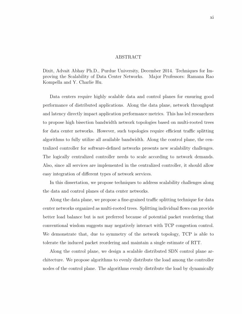
Dixit, Advait Abhay Ph.D., Purdue University, December 2014. Techniques for Im-proving the Scalability of Data Center Networks. Major Professors: Ramana RaoKompella and Y. Charlie Hu.
Data centers require highly scalable data and control planes for ensuring good
performance of distributed applications. Along the data plane, network throughput
and latency directly impact application performance metrics. This has led researchers
to propose high bisection bandwidth network topologies based on multi-rooted trees
for data center networks. However, such topologies require e�cient tra�c splitting
algorithms to fully utilize all available bandwidth. Along the control plane, the cen-
tralized controller for software-defined networks presents new scalability challenges.
The logically centralized controller needs to scale according to network demands.
Also, since all services are implemented in the centralized controller, it should allow
easy integration of di↵erent types of network services.
In this dissertation, we propose techniques to address scalability challenges along
the data and control planes of data center networks.
Along the data plane, we propose a fine-grained tra�c splitting technique for data
center networks organized as multi-rooted trees. Splitting individual flows can provide
better load balance but is not preferred because of potential packet reordering that
conventional wisdom suggests may negatively interact with TCP congestion control.
We demonstrate that, due to symmetry of the network topology, TCP is able to
tolerate the induced packet reordering and maintain a single estimate of RTT.
Along the control plane, we design a scalable distributed SDN control plane ar-
chitecture. We propose algorithms to evenly distribute the load among the controller
nodes of the control plane. The algorithms evenly distribute the load by dynamically

xii
configuring the switch to controller node mapping and adding/removing controller
nodes in response to changing tra�c patterns.
Each SDN controller platform may have di↵erent performance characteristics. In
such cases, it may be desirable to run di↵erent services on di↵erent controllers to
match the controller performance characteristics with service requirements. To ad-
dress this problem, we propose an architecture, FlowBricks, that allows network oper-
ators to compose an SDN control plane with services running on top of heterogeneous
controller platforms.

1
1 INTRODUCTION
Distributed applications such as three-tier web applications and distributed big data
applications (e.g., Hadoop) running in large data centers support a bulk of the web
and business services. Due to the distributed nature of these applications, the data
center network characteristics directly impact application performance metrics such
as query processing rate and completion time. This has led to several research initiates
to improve the performance of data center networks. In the data plane, researchers
have proposed topologies with full bisection bandwidth for data center networks based
on multi-rooted trees [1, 2]. These topologies enable all end hosts can communicate
with each other simultaneous at line rate without any bottlenecks at core links. At the
control plane, SDN paradigm has gained popularity due to ease of management and
faster convergence. However, a centralized SDN controller cannot manage large data
center networks. So, researchers have proposed physically distributed SDN controller
architectures that can handle the demands of large data centers. Data center network
operators prefer to introduce new service through the SDN controller rather than
middleboxes thus, adding to the complexity of designing an SDN controller. To
address the growing number of network services and scalability challenges, researchers
have proposed flexible modular open source SDN controller architectures which enable
dynamic introduction and configuration of new services.
However, the unique characteristics of data center networks present new chal-
lenges. Recent experiments for characterizing data center tra�c have found signifi-
cant spatial and temporal variation in tra�c volumes [1, 3, 4], which means that the
data center network design cannot pre-assume a given tra�c matrix and optimize the
routing and forwarding for it. Recent trends therefore favor network fabric designs
based on multi-rooted tree topologies with full bi-section bandwidth (or with low
oversubscription ratios such as 4:1) such as the fat-tree topologies [2]. In such topolo-

2
gies, traditional single-path routing is inadequate since the full bi-section bandwidth
guarantee assumes that all paths that exist between a pair of servers can be fully
utilized. Thus, equal-cost multipath (ECMP) has been used as the de facto routing
algorithm in these data centers. However, because not all flows are identical in their
size (or their duration), this simple scheme is not su�cient to prevent the occurrence
of hot-spots in the network. Several solutions (e.g.,, Hedera [5], Mahout [6]) focus
on addressing this hot-spot problem by tracking and separating long-lived (elephant)
flows along link-disjoint paths. However, it is fundamentally not always feasible to
pack flows of di↵erent size/duration across a fixed number of paths in a perfectly
balanced manner. A recently proposed solution called MP-TCP [7] departs from the
basic assumption that a flow needs to be sent along one path, by splitting each flow
into multiple sub-flows and leveraging ECMP to send them along multiple paths.
Since MP-TCP requires significant end-host protocol stack changes, it is not always
feasible in all environments, especially in public cloud platforms where individual
tenants control the OS and the network stack. Further, it has high signaling and
connection establishment complexity for short flows, which typically dominate the
data center environment [3, 4].
Along the control plane, a few recent papers have explored architectures for build-
ing distributed SDN controllers [8–10]. While these have focused on building the
components necessary to implement a distributed SDN controller, one key limitation
of these systems is that the mapping between a switch and a controller is statically
configured, making it di�cult for the control plane to adapt to tra�c load variations.
Real networks (e.g., data center networks, enterprise networks) exhibit significant
variations in both temporal and spatial tra�c characteristics. First, along the tem-
poral dimension, it is generally well-known that tra�c conditions can depend on the
time of day (e.g., less tra�c during night), but there are variations even in shorter
time scales (e.g., minutes to hours) depending on the applications running in the
network. Second, there are often spatial tra�c variations; depending on where appli-
cations are generating flows, some switches observe a larger number of flows compared

3
to other portions of the network. Now, if the switch to controller mapping is static,
a controller may become overloaded if the switches mapped to this controller sud-
denly observe a large number of flows, while other controllers remain underutilized.
Furthermore, the load may shift across controllers over time, depending on the tem-
poral and spatial variations in tra�c conditions. Hence static mapping can result
in sub-optimal performance. One way to improve performance is to over-provision
controllers for an expected peak load, but this approach is clearly ine�cient due to
its high cost and energy consumption, especially considering load variations can be
up to two orders of magnitude.
However, each SDN controller architecture will have its own performance char-
acteristics which are best suited for certain applications. Some controllers may be
suitable for high throughput while others may have low response times. In such
cases, it may be desirable to run di↵erent services on di↵erent controllers to match
the controller performance characteristics with service requirements. With the grow-
ing number and complexity of network services, all service implementations may not
be available for a SDN controller platform. This, along with the incompatibility be-
tween SDN controller, motivates the need for a framework that can easily integrate
services implemented on di↵erent SDN controller platforms.
In this dissertation, we propose three techniques to improve the scalability of
data and control planes in data center networks. Along the data plane, we address
scalability with growing network bandwidth demand. Along the control plane, we
address scalability in two ways. We allow the controller to scale with changing control
plane processing and tra�c demands. We also enable the controller to scale with
growing number of network services. One key design principle that we adopted in
our solutions is that they should work with existing network protocols as far as
possible. For example, a large majority of the tra�c in data centers uses TCP [11].
So, it is important to improve data center tra�c without requiring any changes to
TCP. Similarly, OpenFlow has become one of the prominent standards for SDN-based

4
control planes in data centers (e.g., Google [12]). We tried to adhere to the OpenFlow
standard as much as possible for maximum impact.
In the first part of the dissertation, we propose random packet spraying (RPS) as
an e↵ective tra�c splitting technique for data center networks that have multi-rooted
tree topologies. We key observation is that the duplicate-acknowledgment threshold
and packet reordering detection schemes built into TCP are su�cient to make TCP
robust to any packet reordering that may be introduced by RPS. Using a data center
testbed with RPS implemented on NetFPGA switches, we show that RPS performs
better than ECMP and similar to MP-TCP (for long-lived flows). We study the
adverse e↵ects of link failures on RPS and propose an approach based on Random
Early Discard (RED [13]) to mitigate these adverse e↵ects.
In the second part of this dissertation, we propose algorithms to dynamically
scale the computing resources and throughput of a distributed SDN controller in
response to control plane tra�c demands. To achieve this, we propose a seamless
switch migration algorithm, an algorithm to redistribute network load evenly among
controller nodes and an algorithm to add or remove controller nodes.
Finally, we propose a framework for combining network services implemented on
di↵erent SDN controller platforms. This is done without modifying the controllers
themselves and relying entirely on the standardized southbound API.
1.1 Thesis Statement
This dissertation proposed techniques to improve the performance of the control
and data plane in data center networks. We achieve this using new techniques that
are based on existing network protocols.
The thesis of this dissertation is as follows: We can improve the performance of
data plane and control plane in modern data center networks using practical easy-to-
deploy techniques.

5
1.2 Contributions
This dissertation makes three major contributions towards improving data center
network performance:
• Along the data plane, we propose random packet spraying as a technique that can
significantly improve the latency and throughput of data center networks that have
symmetric multi-rooted tree topologies. For dealing with failures that destroy the
symmetry of the network topology, we propose SRED, a combination of RED and
drop-tail queue management algorithms that reduces the negative impact of RED
on network throughput.
• Along the control plane, we propose an OpenFlow-compliant switch migration
algorithm that can seamlessly handover control of a switch from one controller
node to another of a distributed SDN control plane. Using this algorithm as
a building block, we built ElastiCon, a distributed SDN controller that can add
or remove controller nodes in response to network tra�c demands and evenly
distributes the load among controller nodes.
• We designed and prototyped FlowBricks, a framework that allows network operators
to combine best-in-class network services that may be running on di↵erent SDN
control planes. FlowBricks is designed to operate in a way that is transparent to
the controllers and does not require additional standardization.
1.3 Dissertation Organization
This dissertation contains five chapters. In Chapter 3, we show that RPS is an
e↵ective tra�c splitting technique for data centers networks with symmetric multi-
rooted tree topologies. Chapter 4 describes the design and experimental evaluation of
ElastiCon, a scalable distributed SDN controller. In Chapter 5, we present FlowBricks,
a framework for composing a control plane from services running on heterogeneous
SDN controllers. Finally, we present our conclusions and potential directions for
future work in Chapter 6.
6
2 BACKGROUND
Data centers are the core of the internet computing infrastructure. Their sizes range
from a few hundred server owned by small and mid-sized corporations to over 100,000
servers operated by big firms and governments. These data centers may be used to
run web-services or run big data applications. Data centers can benefit enormously by
the economies of scale. This has two consequences. First, large corporations have con-
solidated their data centers into a few large facilities around the globe. Second, small
firms find it more economical to rent computing and storage resources in large data
centers rather than operate their own data centers. The scale of these data centers
means that any performance and utilization improvements achieved here translate
to large financial gains for the data center operators. This has spurred researchers
to explore various avenues for improving all aspects of data centers including stor-
age [14], network [12] and processing at end hosts [15]. In this dissertation, we focus
on improving the scalability of networks that connect the host in a data center.
2.1 Data Center Network Performance
Data center network throughput and latency are important performance met-
rics since they have been shown to directly a↵ect application performance [16]. Re-
searchers have explored various directions for improving these metrics in data centers.
New data center network topologies and switch architectures [17] try to address this
problem at the physical layer. Such e↵orts have focussed on increasing bisection
bandwidth while reducing costs by using commodity components. Since they use
commodity hardware, tra�c needs to be split across several low bandwidth links to
utilize all the available bandwidth. [2] proposes a fat-tree topology which uses the
entropy in the IP address bits to spread tra�c across all available paths. VL2 [1] also

7
uses a multi-rooted tree topology but has higher bandwidth 10Gbps links at the core
and 1Gbps links at the edge switches. It uses virtual IP address and a scheme called
valiant load balancing (VLB) to split tra�c. Bcube [18] proposes a server centric
architecture. Server, in addition to performing computation, act as relay nodes for
each other.
Most data center network topologies have multiple paths between end hosts and
require a tra�c splitting technique to fully utilize all paths. The most commonly
used technique is ECMP which does not make any assumptions about the underlying
topologies. In ECMP, flows (as identified by the TCP 5-tuple) between a given pair
of servers are routed through one of the paths using hashing; therefore, two flows
between the same hosts may take di↵erent paths, and ECMP does not a↵ect TCP
congestion control. However, because not all flows are identical in their size (or their
duration), this simple scheme is not su�cient to prevent the occurrence of hot-spots
in the network. In a recent study [3], the authors find that 90% of the tra�c volume is
actually contained in 10% of flows (heavy-hitters); if two heavy-hitter flows are hashed
to the same path, they can experience significant performance dip. Several solutions
(e.g.,, Hedera [5], Mahout [6]) focus on addressing this hot-spot problem by tracking
and separating long-lived (elephant) flows among link-disjoint paths. However, it is
fundamentally not always feasible to pack flows of di↵erent size/duration across a
fixed number of paths in a perfectly balanced manner. A recently proposed solution
called MP-TCP [7] departs from the basic assumption that a flow needs to be sent
along one path, by splitting each flow into multiple sub-flows and leveraging ECMP to
send them along multiple paths. Since MP-TCP requires significant end-host protocol
stack changes, it is not always feasible in all environments, especially in public cloud
platforms where individual tenants control the OS and the network stack. Further,
it has high signaling and connection establishment complexity for short flows, which
typically dominate the data center environment [3, 4].
A large majority of network tra�c in data centers uses TCP [11]. This has led
researchers to investigate the performance of TCP in data center environments and
8
propose improvements. The TCP incast problem was commonly observed in data
center networks with MapReduce [19] or distributed storage workloads. ICTCP [20],
a variant of TCP, tries to solve the incast problem by proactively adjusting the re-
ceive window before packet drops occur. To reduce queuing latency in the network,
DCTCP [21] proposes using ECN in the network to provide multi-bit feedback to end
hosts. D2TCP [22] also uses ECN bits for congestion avoidance but uses deadlines
to e�ciently allocate bandwidth in a distributed manner. These TCP enhancements
need to ensure that they can co-exists with existing TCP variants. But, they have
limited utility to data center operators because network stacks on the end host are
controlled by tenants in public data centers.
2.2 SDN and Data Center Networks
The benefits of softwared-defined networking (SDN) have led data center oper-
ators to adopt the SDN paradigm for managing their networks [12]. SDN moves
the control plane logic out of the switches to a centralized entity called a controller.
It uses a standardized protocol to configure the data plane in the switches. While
OpenFlow [23] is currently the preeminent standardized protocol and switch specifi-
cation for SDNs, researchers have proposed new switch architectures [24] that provide
features not currently supported in OpenFlow. For example, [25] proposes allowing
end hosts to embed a small list of instructions in a packet. These instructions are
executed at every router along the path of the packet. This allows end hosts to query
and change network state which can be used for a wide range of purposes.
The centralized SDN control plane provides many benefits to data center oper-
ators. It allows easy management of the network through a centralized controller
interface. Researchers have proposed innovative ways to leverage the global view of
the centralized controller to improve the manageability of SDNs. NetSight [26] intro-
duces the idea of “postcards” the contain complete information about a packet header
and switch forwarding state at a particular hop of the packet. By correlating infor-

9
mation from postcards collected from di↵erent packets at each hop, the centralized
server can infer a variety of problems in the network. VeriFlow [27] allows operators
to verify network invariants in real time and across updates to the forwarding state
in the network.
SDNs let data center operators introduce new services (such as NAT, tra�c mon-
itoring) with just a software upgrade of the controller instead of deploying and main-
taining service-specific middleboxes. Data center operators complete control over the
implementation of network services without relying on switch vendors. This has dras-
tically reduced costs but increased the complexity of developing new network services
for the centralized controller. New programming languages such as Pyretic [28] aim
to simplify the development of new services by abstracting away switch hardware
and protocol-specific details to common layer. To address backward-compatibility
of SDNs with existing middleboxes, researchers have proposed techniques to enforce
policies to route tra�c through middleboxes [29].

10
3 RANDOM PACKET SPRAYING
In this chapter, we study the feasibility of an intuitive and simple multipathing scheme
called random packet spraying (RPS), in which packets of every flow are randomly
assigned to one of the available shortest paths to the destination. RPS requires no
changes to end hosts, and is practical to implement in modern switches. In fact, many
commodity switches today (e.g., Cisco [30]) already implement a more sophisticated
per-destination round-robin packet spraying technique.
RPS approach, however, can potentially result in reordering of packets that be-
long to a flow—a problem that is known to negatively interact with TCP congestion
control1, at least in the wide-area networks [31]. Specifically, packets in a given flow
that traverse multiple paths with potentially di↵erent latencies may arrive at the re-
ceiver out of order, i.e., later-sent packets may be received ahead of earlier-sent ones.
Since TCP can not distinguish reordered packets from lost packets, it will trigger
congestion avoidance by cutting down its congestion window leading to suboptimal
performance. Because of the potential packet reordering and its implication on TCP,
networking researchers as well as practitioners have cautiously kept packet spraying
out of consideration for data center networks.
In this chapter, we make two key observations that together suggest RPS is un-
likely to be a↵ected by packet reordering and hence a promising multipathing scheme
for data center networks. First, we observe that modern data center networks based
on multirooted tree topologies tend to be symmetrical, which essentially causes links
along multiple paths between a source-destination to be grouped into equivalence
classes. As a result, paths between a source-destination pair are likely to exhibit
similar queue build-up, keeping latencies roughly equal. In addition, data center net-
1This is the reason that the feature though supported in commodity switches is not turned on bydefault
11
works are often engineered to provide low latencies to service latency sensitive tra�c
anyway. Solutions such as DCTCP [21] and HULL [32] provide even lower latencies
at the (slight) expense of throughput. Low end-to-end latencies help RPS since the
worst case latency di↵erential between two paths is also going to be small.
Second, standard TCP originally designed for the wide area Internet already has
a built-in mechanism to tolerate mild packet reordering. In particular, TCP does not
perform fast retransmit unless 3 duplicate ACKs (DUPACKs) arrive for the same
packet. Newer implementations of TCP in the Linux kernel are even more robust
to packet reordering. They use timestamps and DSACK options to detect spurious
fast retransmissions. If a spurious fast retransmission is detected, TCP reverts the
reduction in congestion window size. Also, the TCP duplicate ACK threshold is
dynamically adjusted. Hence, even if some occasional reordering happens in the data
center network under RPS, the reordering may only mildly a↵ect TCP performance.
In this chapter, we conduct an empirical study to validate these observations
and study the overall performance under RPS multipath routing using a real testbed
comprising of hardware NetFPGA-based switches organized in 4-ary fat-tree topology.
Our experiments indicate that our observations typically hold true in practice and as
a result, RPS achieves much better network-wide TCP throughput than ECMP.
While our experiments above show that RPS works well in symmetric topologies,
production data centers are prone to link failures which may disturb the overall
symmetry of the network. Such asymmetry in the topology can potentially lead to
unequal load on links leading to sub-optimal throughput of RPS. However, no prior
studies have quantified the impact of failures on the performance of RPS in data
center networks. Thus, in second part of this chapter, we conduct detailed empirical
analysis of RPS under failure conditions. We observe that if RPS alone is used, it can
lead to significantly lower throughput in failure scenarios. We observe however that
if the queue lengths are kept su�ciently small using simple active queue management
scheme such as Random Early Discard (RED), the performance of RPS can be much
better, almost comparable to complex solutions such as MP-TCP.

12
COREC2
A1 A2 A4A3
T1 T3 T4
C3 C4
A5 A6 A8A7
T6 T7 T8T5
C1
T2
S1 S5 S7 S11 S13 S15S9S3S2 S6 S8 S12 S14 S16S10S4
Equivalence Class
Figure 3.1.: Fat-tree topology with equivalence classes and imbalance with ECMP.
Contributions. In summary, the main contributions of the chapter include the
following. (1) We conduct a first of its kind empirical study to debunk the myth that
random packet spraying is inherently harmful to TCP, in the context of designing
an e↵ective multipathing scheme for data center networks. (2) Using a data center
testbed with real RPS implementation over NetFPGA switches, we conduct detailed
study on the reasons why RPS performs better than existing schemes such as ECMP
and similar to MP-TCP (with long-lived flows). (3) We also study the adverse e↵ect
of link failures on the performance of RPS. Exploiting the key insight that smaller
queues result in better performance even under failures, we propose an approach
based on RED to mitigate these adverse e↵ects.
3.1 Random Packet Spraying (RPS)
In this section, we start with an overview of RPS followed by theoretical analysis
on why we expect RPS to perform well in data center networks.

13
3.1.1 RPS Overview
The basic idea of RPS is simple: Like ECMP, RPS uses all the equal-cost shortest
paths between every source and destination pair. However, instead of hashing the
flow key of a packet to determine the next hop for forwarding as in ECMP, RPS
randomly spreads all packets that belong to each flow equally along di↵erent shortest
paths. For example, in Figure 3.1, we show a flow from S1� S16 that traverses the
paths S1! T1! {A1, A2}! {C1, C2, C3, C4}! {A7, A8}! T8! S16 to reach
the destination. Thus, if the flow consists of 100 packets, roughly 25 packets will be
routed through each of the four paths via core routers C1� C4.
As shown before in literature [31], packet spraying can lead to severe packet re-
ordering in the wide-area—the packets of a flow which take di↵erent paths may have
orders of magnitude di↵erences in latencies since there is no guarantees that the paths
will be of equal lengths or have similar congestion. Even in data center environments,
where latencies are low and uniform, RPS will potentially introduce packet reordering.
TCP performs poorly in the presence of packet reordering. When the TCP sender
receives three duplicate acknowledgments (DupACK), it assumes that a segment has
been lost and reduces its congestion window size, which results in a drop in through-
put. TCP maintains an estimate of round-trip (RTT) times. If paths have hugely
varying latencies, TCP’s RTT estimate will also be meaningless, which can lead to
spurious retransmissions and timeouts. In fact, this concern of potential packet re-
ordering is why none of the existing data centers use or existing proposals advocate
the use of simple packet spraying schemes.
We make three key observations that indicate that packet spraying techniques like
RPS are unlikely to result in significant packet reordering, and consequently should
not a↵ect TCP’s performance in data center networks that employ multi-rooted tree
topologies such as the fat-tree. Specifically:
Observation 1. In a multirooted tree topology like a fat-tree shown in Figure 3.1,
links can be grouped together into equivalence classes. All links within each equiv-
14
alence class have equal amount of load if all flows in the networks use RPS. Thus,
even though each flow is routed along several paths, each of these paths is similarly
loaded. So, the latency di↵erential between these paths is expected to be quite small,
and the amount of induced reordering due to packet spraying is likely to be small.
(We analyze this in more detail next.)
Observation 2. TCP congestion control is robust to small amount of packet reorder-
ing in the network anyway. Given that TCP was designed for the wide area network,
where some amount of reordering can happen due to failures and other events. The
sender typically waits for 3 duplicate ACKs to infer that a loss event has occurred after
which it performs fast retransmit and cuts its window in half. Besides this, the TCP
implementation in newer Linux kernels detects spurious fast retransmission using the
DSACK and timestamp options of TCP to rollback any erroneous reductions in the
congestion window [33]. TCP also proactively avoids spurious fast retransmissions in
the future by increasing the DupACK threshold [34].
Observation 3. Even if packet spraying using RPS induces slightly more fast retrans-
mits compared to say a flow based technique like ECMP, the extra loss in throughput,
due to the sender reducing its congestion window by half every time a fast retrans-
mit event occurs, can be a small penalty compared to the better usage of the total
aggregate available bandwidth across all paths. Thus, RPS’ overall performance will
be likely better than that of ECMP.
Further, data center operators are increasingly more concerned about end-to-end
latencies. Thus, future data center designs are likely to ensure low and uniform
latencies, using mechanisms such as HULL [32], DCTCP [21], DeTail [35]. If latencies
across all paths are low and uniform, TCP end-host can maintain a single estimate
of RTT for all paths.
In spite of low latencies in data center networks and improvements to TCP, re-
searchers have focused mainly on load balancing schemes which avoid packet reorder-
ing. No measurement studies have been conducted to study the impact of these
improvements on packet spraying in data center networks. Our analysis shows that

15
TCP is able to perform well with packet spraying in a data center environment, as
long as packets are sprayed over equal length paths and queue lengths are kept almost
equal along all paths. We hope that this result will encourage more research in simple
packet spraying techniques for data centers.
3.1.2 Analysis
We formalize the concept of equivalence classes stated in Observation 1 above,
which gives a key reason why di↵erent from in the Internet, significant packet re-
ordering is unlikely to happen when RPS is running in data center networks which
typically employ multi-rooted tree typologies such as fat trees.
When RPS is used to route packets between a source and a destination via all
equal-cost paths, an equivalence class comprises all outgoing links from the switches
at the same hop along all the equal-cost paths. For simplicity, we exclude links
to/from end hosts (leaves in the tree) in the discussion. In a depth-h K-ary fat tree
(each switch has K ports), each flow goes through 2h-hop equal-cost paths and passes
through 2h equivalance classes of links. Note di↵erent source-destination pairs can
share some equivalance classes. Together, there are 2h types of equivalance classes in
a depth-h fat tree. In particular, there are 4 equivalance classes in the depth-2 fat
tree in Figure 3.1:
Type 1: A Type 1 class consists of the links from a ToR switch, ToRi
, to the K
2
aggregate switches Aggj
within the same pod.2
Type 2: A Type 2 class is the mirror image of a Type 1 class, and consists of the
links from the K
2 aggregate switches Aggj
within a pod, to a ToR switch, ToRi
.
Under RPS, for an X-packet flow, the expected number of packets that will be
routed through each of the K
2 links in a Type 1 or Type 2 equivalence class is 2XK
.
Type 3: A Type 3 class consists of the links from all the aggregate switches Aggi
within a pod, to all K
2
4 core switches, Cn
.
2The set of switches {T1,T2,A1,A2}, {T3,T4,A3,A4}, etc. in Figure 3.1, are referred to as pods inthe fat-tree.
16
Type 4: A Type 4 class is the mirror imagine of a Type 3 class, and consists of
the links from all the core switches Cn
, to all aggregate switches, Aggj
, within a pod.
Under RPS, for an X-packet flow, the expected number of packets that will be
routed through each of the K
2
4 links in a Type 3 or Type 4 equivalence class is 4XK
2 .
Example. Consider the two paths between S1 and S5 in Figure 3.1. There are
four equal-cost paths between them. The first hops of all paths form to the Type 1
equivalence class (T1 ! A1, T1 ! A2), the second hops of all paths belong to the
Type 3 equivalence class (A1 ! C1, A1 ! C2, A2 ! C3, A2 ! C4), and so on.
This hop-by-hop equivalence holds for paths between all hosts in the fat tree even if
they are in di↵erent pods, in the same pod, or under the same ToR switch.
The equal spread of packets of each flow among the links in its hop-by-hop equiva-
lence ensures that, given any set of flows, load and hence the queue lengths (measured
in number of packets) among the links in each eqivalent class stays the same. This in
turn implies that for a given flow, its packets traversing di↵erent paths will encounter
the same queuing delay, and hence the same end-to-end delay. Thus, the receiver
will observe only a few reordered packets due to small di↵erences in queue lengths
introduced by (1) di↵erence in packet sizes; (2) flow sizes are not always in multiples
of the number of paths; and (3) timing issues. However, these issues are expected
to cause only a small queue length di↵erential which results in a small amount of
reordering within the network. We experimentally confirm this in Section 3.2.
3.2 Evaluating RPS
In this section, we evaluate RPS using a real hardware testbed. We first discuss the
testbed configuration and our implementation of RPS and ECMP. We then provide
comparisons of RPS with and ECMP and MP-TCP. Finally, we empirically confirm
the three observations made in the previous section that explain the good performance
of RPS in our testbed.

17
3.2.1 Testbed Configuration
Our testbed has 36 servers connected in a 4-ary (k = 4) fat-tree [2] topology
(as shown in Figure 3.1). All the servers are equipped with 4GB RAM, Intel Xeon
2.40GHz quad-core processors running Centos 5.5 and two 1Gbps Ethernet ports. We
have 20 NetFPGA boards, each deployed on a server, and interconnected in a fat-tree
topology via 1 Gbps Ethernet links. Rest of the 16 servers form the endhosts con-
nected to this network. A fat tree has an oversubscription ratio of 1:1. Removing two
of the four core switches would have resulted in an oversubscription ratio of 2:1 but
it would have reduced path diversity; there would be just two paths between hosts in
di↵erent paths, which can bias our results significantly. Other oversubscription ratios
(4:1, 8:1) would not be possible even. To overcome this, we emulate oversubscrip-
tion of approximately 4:1 (and 8:1) by rate-limiting the core links to 230Mbps (and
115Mbps). The seemingly arbitrary choice of 230Mbps (instead of 250Mbps) stems
from the limitations of the NetFPGA rate limiter, which allows only a few discrete
values to choose from.
Implementation of RPS and ECMP
We implemented RPS and ECMP on NetFPGA switches by modifying the code
base already provided by NetFPGA. For a packet arriving at the switch, we generate
a random number (using the library provided by NetFPGA) to determine the output
port (among all eligible output ports) to which the packet is forwarded. Implementing
this is quite simple; we needed only about 100 lines of verilog code to implement this
technique. RPS is a purely switch-based solution and does not require any help or
modification at the end hosts.

18
Implementation of MP-TCP
To enable MP-TCP, we deployed the publicly released Linux kernel for MP-
TCP [36] at the end hosts. This kernel still has a few performance and stability
problems. For instance, we observed kernel panics sometimes when MP-TCP was
handling many short-sized flows simultaneously. This prevented us from running ex-
periments involving many short flows with the MP-TCP kernel. For long flows, we
observed more stable results for MP-TCP. MP-TCP has also been noted to have a
sub-standard performance with short flows because the control overhead of setting
up and terminating many subflows becomes significant. For the above reasons, we
present MP-TCP results for long flows in this dissertation. Since ECMP performs
well with short and long flows, we compare RPS with ECMP in experiments involving
both short and long flows.
3.2.2 TCP Throughput under Packet Spraying
We first measure the throughput obtained by long lived TCP flows in a random
permutation matrix (similar to [7]). In such a setup, each host in the topology is
either a sender or a receiver of exactly one TCP flow. All senders are randomly
paired with receivers. A netperf client running at the sender sends a TCP flow to
its receiver for the duration of the experiment. We measure the average throughput
as a percentage of the ideal throughput and also compare performance of TCP flows
under di↵erent schemes.
Figure 3.2 clearly depicts the gain in throughput experienced by TCP flows under
a packet spraying technique (RPS). Even under di↵erent degrees of oversubscription,
the throughput obtained under RPS is higher than those measured under MP-TCP
or ECMP-like techniques. The low average throughput in case of ECMP-based for-
warding can be attributed to the fact that two or more TCP flows may be forwarded
over the same core link which becomes a bottleneck. For the entire flow duration
of the flow, that link remains the hot spot in the network while leaving other links

19
underutilized. Due to static allocation of paths in ECMP, if some of the flows are
unlucky and are routed through a congested link, then they su↵er permanently for
the entire duration resulting in poor throughput.
0
20
40
60
80
100
1:1 4:1 8:1
Th
rou
gh
pu
t (a
s %
ag
e o
f id
ea
l)
ECMPRPS
MPTCP
Figure 3.2.: Throughput for permutation matrix
Under RPS, average throughput achieved is about 90% of the ideal bandwidth
in all 3 cases with di↵erent oversubscription ratios. Figure 3.2 also demonstrates
that the variance in throughput obtained by di↵erent TCP flows is small. MP-TCP
also achieves about 90% in case of a non-oversubscribed topology (subscription factor
1:1). This is consistent with results reported in [7] for a similar experimental setup.
In case of oversubscribed topology though, the average throughput achieved by MP-
TCP flows seems to su↵er and it decreases from 90% to about 75%. This poor
performance may be an artifact of MP-TCP itself or the released implementation of
MP-TCP; unfortunately, there is no easy way for us to know precisely at the moment.
To study the e↵ect of path diversity on RPS, we repeated the above experiment
in simulation using fat trees with (k =) 6 and 8 pods. The number of paths between
end hosts is 9 and 16 respectively (k2/4). Intuitively, when the number of paths
increases, the probability of packet reordering in packet spraying increases. However,
we observed that the drop is not substantial showing that our analysis in Section 3.1.2
still largely holds.

20
3.2.3 Data Transfer Time
We repeat the experiment performed in [7] (but with mixed short and long flows)
to study how much time TCP takes to transfer the same amount of data under
di↵erent schemes. This experiment shows the ability of the underlying mechanism
to consume bandwidth more e�ciently to transfer the same amount of data. In this
experimental setup, each end host executes two clients which have to transfer 2GB of
total data, which is divided into many flows with flow sizes drawn from the real data-
center flow size distribution reported in [1]. A client sends these flows in sequence
to randomly chosen destinations. The client forks a new netperf client for each flow.
All clients begin simultaneously. We plot the median, and first/third quartiles of the
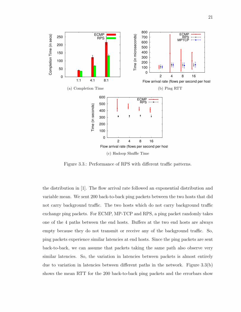
completion time of all clients in Figure 3.3(a).
We observe that TCP flows are able to complete faster under RPS as compared
to ECMP. (We cannot do this experiment with MP-TCP as it is unstable when there
are large number of concurrent connections.) With 1:1 oversubscription, we observe
that ECMP and RPS perform equally well. This is because in such a topology and
flows being setup between random pairs of hosts, the edge links are more likely to
be the bottleneck than the core of the network. So, TCP does not benefit from a
better tra�c splitting technique. In case of 4:1 or 8:1 oversubscribed networks, the
packet spraying technique helps TCP flows to utilize the available capacity in a much
more e�cient manner in spite of the reordering. Hence, the time to transfer the same
amount of total data is 25% smaller in case of RPS than ECMP.
3.2.4 Packet Latencies
Packet latency is another important metric for flows in data center networks.
Recent works like [21, 32] have focused on reducing packet latencies in the network
so that applications can satisfy SLAs (service level agreements). To study the e↵ect
of packet spraying on packet latencies we ran background tra�c between 14 (out of
16) end hosts in our testbed. The flow sizes for background tra�c were drawn from
21
0
50
100
150
200
250
1:1 4:1 8:1
Co
mp
letio
n T
ime
(in
se
cs) ECMP
RPS
(a) Completion Time
0
100
200
300
400
500
600
700
800
2 4 8 16
Tim
e (
in m
icro
seco
nd
s)
Flow arrival rate (flows per second per host)
ECMPRPS
MPTCP
(b) Ping RTT
0
100
200
300
400
500
600
2 4 8 16
Tim
e (
in s
eco
nd
s)
Flow arrival rate (flows per second per host)
ECMPRPS
(c) Hadoop Shu✏e Time
Figure 3.3.: Performance of RPS with di↵erent tra�c patterns.
the distribution in [1]. The flow arrival rate followed an exponential distribution and
variable mean. We sent 200 back-to-back ping packets between the two hosts that did
not carry background tra�c. The two hosts which do not carry background tra�c
exchange ping packets. For ECMP, MP-TCP and RPS, a ping packet randomly takes
one of the 4 paths between the end hosts. Bu↵ers at the two end hosts are always
empty because they do not transmit or receive any of the background tra�c. So,
ping packets experience similar latencies at end hosts. Since the ping packets are sent
back-to-back, we can assume that packets taking the same path also observe very
similar latencies. So, the variation in latencies between packets is almost entirely
due to variation in latencies between di↵erent paths in the network. Figure 3.3(b)
shows the mean RTT for the 200 back-to-back ping packets and the errorbars show
22
the mean deviation reported by ping. We observed that the latency varied widely
with ECMP indicating that di↵erent paths between the two hosts di↵erent loads.
Packets experience similar mean latencies with RPS and MP-TCP, but experience
higher variance with MP-TCP.
3.2.5 E↵ect on MapReduce
In order to quantify the impact of packet spraying on applications, we run Hadoop
Sort application on 4 of the 16 end hosts in our testbed (other 12 hosts have back-
ground tra�c between them as before). To emulate a network constrained cloud
application, we reduce the bandwidth of each link to 115Mbps but kept the oversub-
scription ratio at 1:1.
Figure 3.3(c) shows the time taken for the shu✏e phase of Hadoop sorting 4GB
of data averaged over 3 runs. On the x-axis, we vary the intensity of background
tra�c (that is, flow arrival rate of background tra�c). We observe a 20% to 30%
reduction in shu✏e time with RPS. Also, the variance in completion time is much
smaller with RPS than ECMP. Since a fat-tree is provides full bisection bandwidth,
end hosts running Hadoop can communicate with each other at full line rate even when
background tra�c intensity increases. So, increasing background tra�c intensity does
not a↵ect shu✏e phase completion time. RPS completes the sort phase quicker than
ECMP because it is able to utilize the available bisection bandwidth more e�ciently
than RPS. We were not able to perform this experiment with MP-TCP due to the
stability issues with MP-TCP implementation.
3.2.6 Analysis of Packet Spraying
Now, we conduct experiments to validate our analysis and our understanding of
why TCP performs well under packet spraying in data center networks. Specifically,
we empirically validate our key observations made in Section 3.1 using experiments
conducted on our testbed. In these experiments, each end host starts new flows with
23
-1
0
1
2
3
4
0 0.5 1 1.5 2 2.5 3 3.5 4 4.5
# o
f p
kts
Time (secs)
Path-length-diff
(a) Q-length di↵. across a src-dest pair
1
10
100
1000
10000
100000
1e+06
1e+07
0 1 2 3 4 5 6 7 8 9
Fre
quency
# of Dupacks
ECMPRPS
(b) # of consecutive DupAcks
0
200
400
600
800
1000
0 200 400 600 800 1000
EC
MP
-Thro
ughput (M
bps)
�PS-Throughput (Mbps)
Thpt-smallThpt-large
(c) Throughput comparison with ECMP
Figure 3.4.: Microscopic analysis to validate our understanding of RPS performance.
start times based on a Poisson distribution with 2 arrivals per second. As before, flow
sizes are drawn from the distribution reported in [1]. The tra�c matrix was executed
two times, once each for ECMP and RPS. Both times, the random number seeds were
initialized to the same value to ensure that flows of the same size were started at the
same time in both runs, allowing us to make a flow-by-flow comparison between RPS
and ECMP.
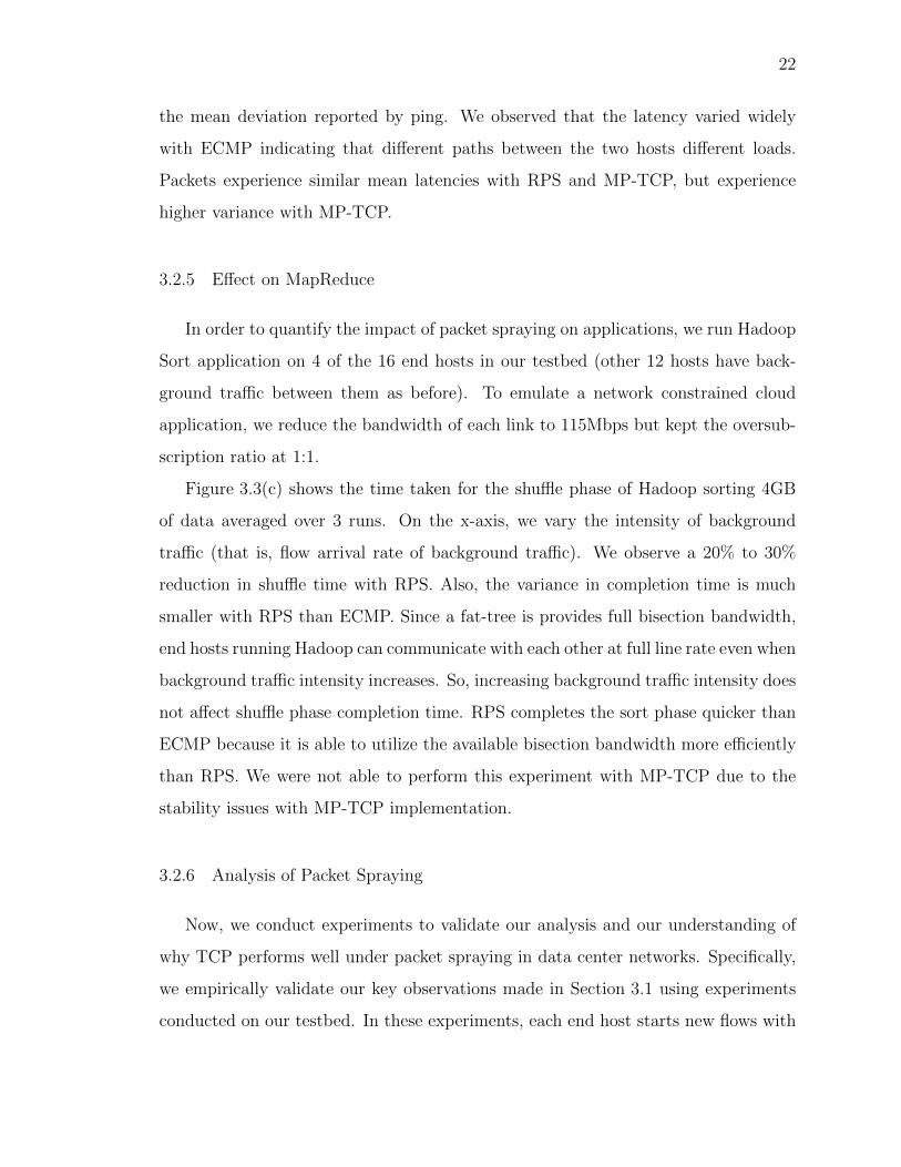
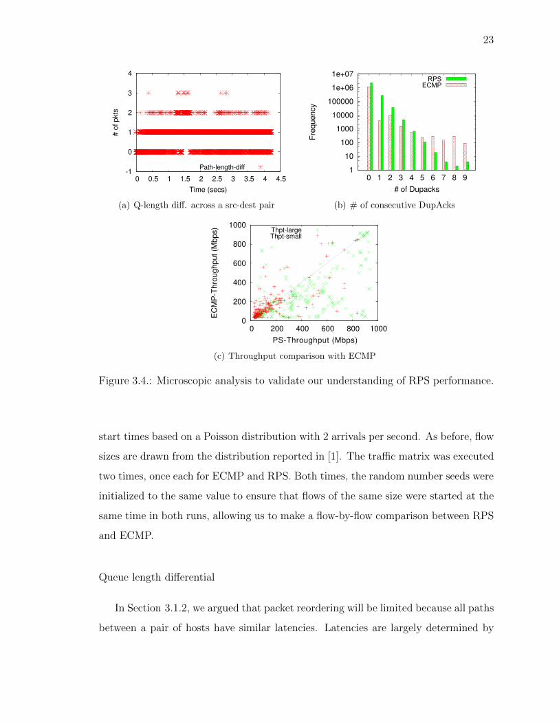
Queue length di↵erential
In Section 3.1.2, we argued that packet reordering will be limited because all paths
between a pair of hosts have similar latencies. Latencies are largely determined by

24
queue lengths that a packet encounters at every hop. We polled the queue lengths at
every hop along a path between a pair of hosts in our testbed. We were able to poll
about 1000 times per second; this is the maximum rate allowed by our NetFPGA
platform. We used NTP to synchronize timestamps at all switches. By summing the
queue lengths of all hops, we determined the path queue-length, that is, the total
queue-length that a packet would encounter if it were forwarded along that path. We
did this for all paths between a source destination pair and plotted the instantaneous
di↵erence between the highest and the lowest path queue-lengths in Figure 3.4(a).
In a perfectly balanced network, this path queue-length di↵erential will always be
zero. However, in Figure 3.4(a), the queue-length di↵erential is less than or equal to
one 93% of the time. Flows between the pair of end hosts under observation may
experience some reordering when the path queue-length di↵erential increases to two
or three, but that is relatively infrequent (less than 7%).
DupACKs
We now measure the number of dupACKs that an end host will receive. We log the
number of dupACKs received at the sender and plot Figure 3.4(b). The x-axis shows
the number of dupACKs that the sender received for a particular TCP segment. For
both ECMP and RPS, the sender received no dupACKs for almost one million TCP
segments. RPS received exactly one dupACK almost 200,000 TCP segments, and
exactly two dupACKs for 30,000 and so on. We see that the frequency of k dupACKs
reduces exponentially with increasing k.
TCP does not enter fast-retransmission until it sees greater number of dupACKs
than the dupAckThreshold (default is 3). So, the first three bars in the figure will not
lead to a drop in throughput. Since the number of dupACKs reduce exponentially, we
observe that fewer that 55,000 (about 2%) of the transmitted TCP sequence numbers
cross the three dupACK threshold. Surprisingly, we find a similar order of magnitude
dupACKs in ECMP. However, dupACKs in ECMP are entirely due to packet losses

25
and therefore cause a drop in throughput. But, dupACKs in RPS are due to a
combination of reordered and lost packets. While it is di�cult to ascertain the exact
number of reordered and lost packets, note that dupACKs due to reordered packets
are handled well as stock Linux TCP implementation has adaptive dupACKThreshold
to reduce spurious reductions in TCP congestion window due to reordered packets.
In any case, RPS should perform, if not better, no worse than ECMP because of
dupACKs. But, flows have higher available bandwidth in the case of RPS than
ECMP due to the availability of combined bandwidth across all sub-paths, which
increases the performance of RPS compared with ECMP.
E↵ect on throughput of individual flows
We compare the performance of large and small flows in RPS and ECMP. It is
generally expected that small flows should obtain good throughput under ECMP; it is
the large flows that usually su↵er. In Figure 3.4(c), we plot the throughput observed
by the same flows under ECMP and RPS. The x-coordinate of a point corresponds to
a flow’s throughput under RPS while the y-coordinate is its throughput with ECMP.
Points below the diagonal line indicate higher throughput with RPS. The green crosses
represent large flows (greater than 1MB) while the red pluses are for short flows. From
the graph, we can clearly see that large flows benefit most with RPS, while small flows
perform equally well with both ECMP and RPS. Although only 10% of the flows in
the distribution are large, the di↵erence in throughput is significant enough to a↵ect
applications. Also, the number of bytes belonging to large flows is a larger fraction
of the overall network utilization than the number of large flows. We also conducted
a similar experiment as in Section 3.2.3, and observed a significant reduction in data
transfer time. This experiment has an important implication: RPS cannot benefit
much by treating large and small flows di↵erently. Some earlier proposals [5] work
only on large flows and let ECMP handle smaller flows. Since RPS handles small

26
flows just as well as ECMP, we can apply RPS to all flows in the network. This
avoids the additional complexity of trying to identify large flows in the network.
3.3 Handling Asymmetry
So far, we have investigated the behavior of packet spraying in symmetric mul-
tirooted tree topologies. But in the real world, a data center network may not be
symmetric at all times. The data center may have an asymmetric topology to start
with. Even in networks with symmetric topologies, asymmetries may arise due to
various reasons. For instance, a failure condition (link/switch failure or link degra-
dation) can result in an asymmetric topology. Under the above scenarios, di↵erent
paths between a pair of end hosts in the network may see di↵erent levels of congestion.
In Section 3.2.6, we showed that the queue length di↵erential is low in a symmetric
network topology. However, the queue length di↵erential can be significant in an
assymmetric network topology due to the absence of equivalence classes. Below, we
first show how flows su↵er from this queue length di↵erential. We then show how
we can force queue lengths to be almost equal using existing techniques that prevent
queues from growing large.
3.3.1 Problem Illustration
In this section, we use a very simple setup to demonstrate how asymmetries can
impact RPS. We consider two scenarios (failures and mixture of routing strategies)
which we believe are common in data centers.
Two Flow Experiment: We describe our experimental results obtained using the
testbed with an oversubscription ratio of 4:1. Results for the 1:1 and 8:1 are similar
and are hence skipped for brevity. To illustrate the problem, we consider only 2 flows
in the network: flow F1 from S1 to S10 and and flow F2 from S15 to S9 as shown in
Figure 3.5. For this experiment, ignore the shaded box indicating data transfer. Both
flows use RPS and last for the entire duration of the experiment. As expected, F1
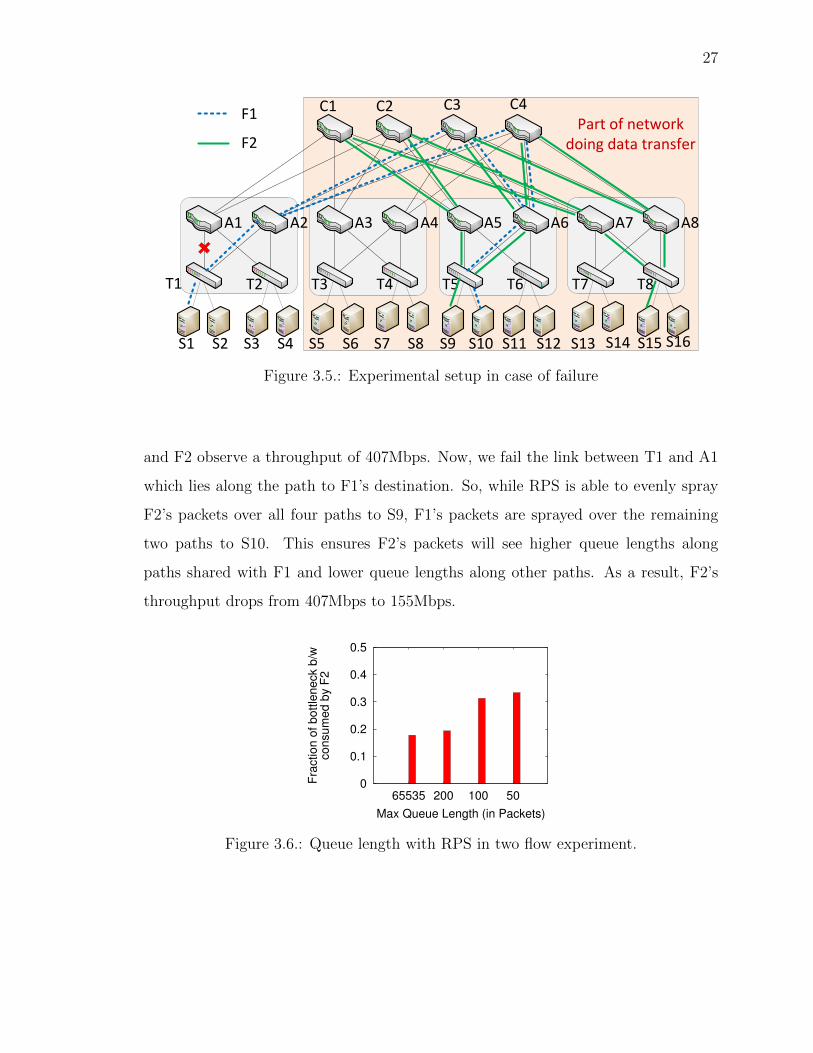
27
C2
A1 A2 A4A3
T1 T3 T4
C3 C4
A5 A6 A8A7
T6 T7 T8T5
C1
T2
S1 S5 S7 S11 S13 S15S9S3S2 S6 S8 S12 S14 S16S10S4
Part of network doing data transfer
F1
F2
Figure 3.5.: Experimental setup in case of failure
and F2 observe a throughput of 407Mbps. Now, we fail the link between T1 and A1
which lies along the path to F1’s destination. So, while RPS is able to evenly spray
F2’s packets over all four paths to S9, F1’s packets are sprayed over the remaining
two paths to S10. This ensures F2’s packets will see higher queue lengths along
paths shared with F1 and lower queue lengths along other paths. As a result, F2’s
throughput drops from 407Mbps to 155Mbps.
0
0.1
0.2
0.3
0.4
0.5
65535 200 100 50
Fra
ctio
n o
f b
ott
len
eck
b/w
con
sum
ed
by
F2
Max Queue Length (in Packets)
Figure 3.6.: Queue length with RPS in two flow experiment.

28
3.3.2 Key Observation
We first demonstrate that the drop in throughput is indeed due to di↵erence in
queue lengths and reducing it alleviates the problem. To do so, in the two-flow exper-
iment setup described above, we statically limit the bu↵er size at the output bu↵er
of all ports in the network. When the output bu↵er is unrestricted, the queue length
di↵erential reaches more that 300 packets. But, limiting the output bu↵er limits the
queue length di↵erential too. However, it also causes a drop in throughput due to
lower link utilization. To find out throughput loss due to queue length di↵erential,
we observe the fraction of the bandwidth that F2 receives at the bottleneck link. A
bottleneck link is always one of the links shared by both flows. So, F2 should always
get 50% of the bottleneck bandwidth. However, as Figure 3.6 shows, when the queue
length is unrestricted (corresponding to the bar at 65535), F2 consumes just 17% of
the bandwidth. Reducing bu↵er sizes reduces the queue length di↵erence between the
paths that carry F2’s packets. As a result, it is able to sustain a higher throughput,
reaching 35% when bu↵er sizes are restricted to 50 packets. This demonstrates that
the higher the queue length di↵erential, the lower the throughput.
3.3.3 A Practical Solution: Keeping Queue Lengths Equal
The queue length di↵erential due to assymetries is the main factor that impacts
RPS performance, but we observe that the extent of this impact is very much depen-
dent on the maximum size a queue is allowed to grow. Modern data center operators
try to keep queue lengths to the minimum to keep end-to-end latencies low and pre-
dictable, which helps RPS. Standard active queue management techniques like RED
and numerous newer solutions [21, 32, 37] can be used to achieve this. Later in this
section, we show how RED improves the performance of RPS in the presence of link
failures. We were not able to test out RPS with newer solutions since they are still
emerging.

29
RED probabilistically drops packets as soon as the queue length crosses some
threshold. Setting the threshold too low results in being aggressive in dropping pack-
ets, and hence, queue length is kept relatively low. However, the total throughput and
utilization is reduced as well. We also introduce a new variant of RED that limits the
ill-e↵ects of RED while still reducing queue length di↵erentials. We call this variant
Selective-RED (SRED). SRED selectively enables RED only for flows that induce a
queue length di↵erential. These are flows which do not use all the multiple paths
(like F1 in the two flow experiment) because of link failures or otherwise. Intuitively,
restricting the queue length share of these flows should reduce the queue length dif-
ferential. Packets of flows using all the paths (like F2) continue to use droptail since
these packets do not contribute to any queue length di↵erentials.
We envision implementing SRED using packet marking and a topology aware
centralized fault manager. When a link fails, the centralized fault manager configures
end hosts or ToR routers to mark all packets of flows a↵ected by that failure. Marking
can be done using TOS bits in the IP header. Downstream routers employ RED only
on marked packets, thus emulating SRED. Other packets are queued and dropped
using droptail policy; this limits the ill e↵ects of RED to only those queues which
induce queue imbalances in the network. While centralized controllers like Hedera [5]
need to respond to new flow arrivals, the fault manager responds only to topology
changes. Hence, it can scale well to larger networks.
SRED requires changes to switches however. Logically, each output port will need
to maintain 2 queues, one using droptail for unmarked packets, while the other using
RED for marked packets. We can of course implement SRED using a single physical
queue itself; unmarked packets are inserted if space is available while marked packets
are queued probabilistically using RED. Only the number of marked packets in the
queue are used to calculate the average queue length used by the RED algorithm.
We now evaluate this idea but a detailed analysis of SRED is left for future work.

30
0
100
200
300
400
500
600
Droptail RED SRED
Th
rou
gh
pu
t o
f F
2 (
in M
bp
s)
(a) Throughput in 2 flow experiment
0
100
200
300
400
500
Droptail RED SRED MPTCP
Th
rou
gh
pu
t (in
Mb
ps)
No FailuresLink Failure
(b) Throughput with permutation matrix
0
20
40
60
80
100
120
140
Droptail RED SRED
Co
mp
letio
n T
ime
(in
se
cs) No Failures
Link Failure
(c) Completion time for data transfer
Figure 3.7.: RPS performance with a link failure.
Two Flow Experiment
We repeat the above experiment with RED (thresholdmax
= 20, thresholdmin
=
10, pmax
= 0.1) enabled at all switches. We observe the throughput of flow F2
under two scenarios: RED is applied to both flows and SRED (RED applied only to
F1’s packets). We want to show that the reduced throughput experienced by F2 is
entirely due to the unequal queue lengths induced by F1’s packets. Hence, limiting
F1 in the routers’ queues should be su�cient to restore F2’s throughput. As seen
in Figure 3.7(a), F2’s throughput falls from 417Mbps in the ideal case to less than
200Mbps when packets from flow F1 are spread over 2 (out of 4) paths. This is

31
expected as F1 creates high queue length di↵erential for packets of flow F2 which are
spread over all the 4 paths.
However, when we restrict the queue length of the switches using RED, the
throughput of F2 increases (to 360 Mbps) resulting from lesser queue length dif-
ferential. It is still low (compared to ideal) as we are limiting the link utilization
by limiting the total queue length. Under SRED, we can clearly observe that F2
gets close to ideal throughput. When using 2 paths under SRED, flow F1 gets a
throughput (not shown in figure) close to 195 Mbps, almost half of the ideal. This is
by design since we believe it is acceptable for flows that are directly impacted by the
failure to su↵er throughput loss, but we want to ensure that other flows not directly
impacted by the failure continue una↵ected.
Permutation Matrix under Failure
We repeat the experiment with a permutation matrix on a 4:1 oversubscribed
topology. As before, we fail the link between A1 and T1. Figure 3.7(b) shows the
average throughput of all the flows which are not a↵ected by the failure and spray
their packets on all four paths. We also compare their average throughput with that
in a topology without failures. With RPS over droptail, the mean throughput of these
flows almost halves as compared to that without failure. RPS in presence of RED
reduces the average throughput of these flows even in the absence of failures (due
to lower link utilization). But, when a failure happens, the mean throughput is not
a↵ected by a lot (changes by less than 10%) due to limits on queue length di↵erential.
SRED is exactly like droptail when there are no failures in the network (since no
flow is subjected to RED). In case of failures, flows a↵ected by failure (using only
2 out of 4 paths in our case) are handled using RED. These flows get an average
throughput of 156Mbps (not shown in graph). Other flows are not a↵ected by the
failure at all and they continue to achieve a high share of throughput. The figure

32
clearly shows that the failure has a negligible impact of the average throughput of
these flows.
Data Transfer Time under Failure
We repeat the experiment in Section 3.2.3 with unequal tra�c splitting. We use
the same oversubscribed fat-tree (4:1) as discussed above. However, we transfer 1GB
of data between hosts in 3 pods as shown in Figure 3.5. We also inject flow F1 from
the 4th pod to a randomly selected host in one of the 3 pods. For this experiment,
ignore flow F2 shown in the figure. We plot the average time taken by the last host to
complete the transfer in Figure 3.7(c) and compare the with and without failure cases.
We average this over 10 runs and the errorbars represent the standard deviation.
A link failure in the 4th pod should not a↵ect the 1GB data transfer because its
tra�c does not traverse this pod. However, the flow which is injected from the 4th
pod creates the queue length di↵erential as it is sprayed over two instead of four
core switches (the other two core switches are inaccessible to this flow due to the
failure). This imbalance greatly increases the data transfer completion time in RPS
with droptail from 36 seconds to 120 seconds. In case of RED, the data transfer
completion time increases marginally from 36 to 48 seconds for the same failure
scenario. With SRED, a failure in the 4th pod has virtually no e↵ect on the tra�c of
the 3 pods and the completion time remains the same.
3.4 Related Work
The most related to our work are those mechanisms that rely on flow-level tra�c
splitting such as ECMP and Hedera [5]. Mahout [6] is a recent scheme that uses end-
host mechanisms to identify elephants, and uses flow scheduling schemes similar to
Hedera. BCube [18] proposes a server-centric network architecture and source routing
mechanism for selecting paths for flows. When a host needs to route a new flow, it
probes multiple paths to the destination and selects the one with the highest available
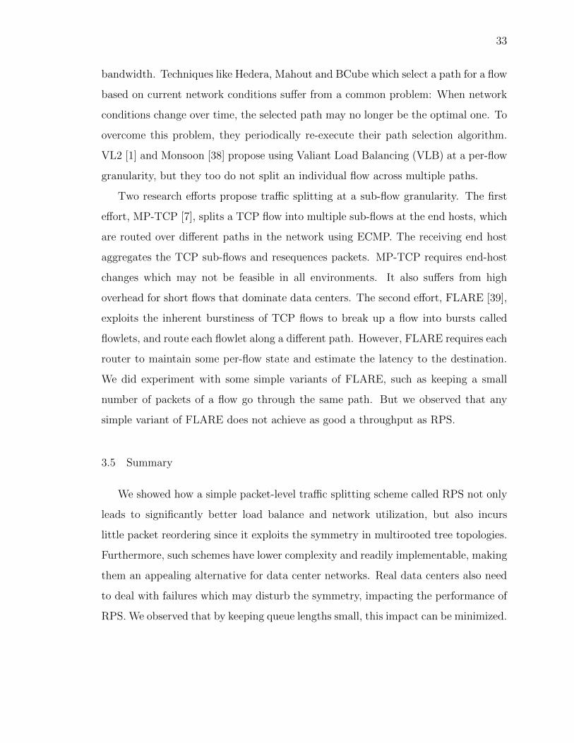
33
bandwidth. Techniques like Hedera, Mahout and BCube which select a path for a flow
based on current network conditions su↵er from a common problem: When network
conditions change over time, the selected path may no longer be the optimal one. To
overcome this problem, they periodically re-execute their path selection algorithm.
VL2 [1] and Monsoon [38] propose using Valiant Load Balancing (VLB) at a per-flow
granularity, but they too do not split an individual flow across multiple paths.
Two research e↵orts propose tra�c splitting at a sub-flow granularity. The first
e↵ort, MP-TCP [7], splits a TCP flow into multiple sub-flows at the end hosts, which
are routed over di↵erent paths in the network using ECMP. The receiving end host
aggregates the TCP sub-flows and resequences packets. MP-TCP requires end-host
changes which may not be feasible in all environments. It also su↵ers from high
overhead for short flows that dominate data centers. The second e↵ort, FLARE [39],
exploits the inherent burstiness of TCP flows to break up a flow into bursts called
flowlets, and route each flowlet along a di↵erent path. However, FLARE requires each
router to maintain some per-flow state and estimate the latency to the destination.
We did experiment with some simple variants of FLARE, such as keeping a small
number of packets of a flow go through the same path. But we observed that any
simple variant of FLARE does not achieve as good a throughput as RPS.
3.5 Summary
We showed how a simple packet-level tra�c splitting scheme called RPS not only
leads to significantly better load balance and network utilization, but also incurs
little packet reordering since it exploits the symmetry in multirooted tree topologies.
Furthermore, such schemes have lower complexity and readily implementable, making
them an appealing alternative for data center networks. Real data centers also need
to deal with failures which may disturb the symmetry, impacting the performance of
RPS. We observed that by keeping queue lengths small, this impact can be minimized.

34
We exploited this observation by proposing a simple queue management scheme called
SRED that can cope well with failures.

35
4 ElastiCon: AN ELASTIC DISTRIBUTED SDN CONTROLLER
SDNs can provide a wide range of services in data center networks. For example, [40]
present a number of user cases such as bandwidth-on-demand and virtual data center.
A bandwidth-on-demand service can provide guaranteed bandwidth to suit applica-
tions demands without requiring any manual configuration. The virtual data center
service can aggregate tra�c from VMs over the network connections/tunnels that
have been discovered and provisioned through SDN. Such services require applica-
tions to communicate their network demands to the SDN controller and the SDN
controller configures network devices to meet those demands. For large data centers,
the SDN controller can become a performance bottleneck for such services.
A few recent papers have explored architectures for building logically centralized
but physically distributed SDN controllers [8–10] to solve this problem. While these
have focused on building the components necessary to implement a distributed SDN
controller, one key limitation of these systems is that the mapping between a switch
and a controller is statically configured, making it di�cult for the control plane to
adapt to tra�c load variations. Real networks (e.g., data center networks, enterprise
networks) exhibit significant variations in both temporal and spatial tra�c charac-
teristics. First, along the temporal dimension, it is generally well-known that tra�c
conditions can depend on the time of day (e.g., less tra�c during night), but there
are variations even in shorter time scales (e.g., minutes to hours) depending on the
applications running in the network. For instance, based on measurements over real
data centers in [11], we estimate that the peak-to-median ratio of flow arrival rates is
almost 1-2 orders of magnitude1 (more details in Section 4.1). Second, there are often
1This analysis is based on the reactive flow installation although our design supports proactive modeas well.

36
spatial tra�c variations; depending on where applications are generating flows, some
switches observe a larger number of flows compared to other portions of the network.
Now, if the switch to controller mapping is static, a controller may become over-
loaded if the switches mapped to this controller suddenly observe a large number
of flows, while other controllers remain underutilized. Furthermore, the load may
shift across controllers over time, depending on the temporal and spatial variations in
tra�c conditions. Hence static mapping can result in sub-optimal performance. One
way to improve performance is to over-provision controllers for an expected peak load,
but this approach is clearly ine�cient due to its high cost and energy consumption,
especially considering load variations can be up to two orders of magnitude.
To address this problem, we propose ElastiCon, an elastic distributed controller
architecture in which the controller pool expands or shrinks dynamically as the ag-
gregate load changes over time. While such an elastic architecture can ensure there
are always enough controller resources to manage the tra�c load, performance can
still be bad if the load is not distributed among these di↵erent controllers evenly. For
example, if the set of switches that are connected to one controller are generating
most of the tra�c while the others are not, this can cause the performance to dip
significantly even though there are enough controller resources in the overall system.
To address this problem, ElastiCon periodically monitors the load on each controller,
detects imbalances, and automatically balances the load across controllers by migrat-
ing some switches from the overloaded controller to a lightly-loaded one. This way,
ElastiCon ensures predictable performance even under highly dynamic workloads.
Migrating a switch from one controller to another in a naive fashion can cause dis-
ruption to ongoing flows, which can severely impact the various applications running
in the data center. Unfortunately, the current de facto SDN standard, OpenFlow
does not provide a disruption-free migration operation natively. To address this
shortcoming, we propose a new 4-phase migration protocol that ensures minimal dis-
ruption to ongoing flows. Our protocol makes minimal assumptions about the switch
architecture and is OpenFlow standard compliant. The basic idea in our protocol
37
involves creating a single trigger event that can help determine the exact moment of
hando↵ between the first controller and second controller. We exploit OpenFlow’s
“equal mode” semantics to ensure such a single trigger event to be sent to both the
controllers that can allow the controllers to perform the hando↵ in a disruption-free
manner without safety or liveness concerns.
Armed with this disruption-free migration primitive, ElastiCon supports the fol-
lowing three main load adaptation operations: First, it monitors the load on all
controllers and periodically load balances the controllers by optimizing the switch-to-
controller mapping. Second, if the aggregate load exceeds the maximum capacity of
existing controllers, it grows the resource pool by adding new controllers, triggering
switch migrations to utilize the new controller resource. Similarly, when the load
falls below a particular level, it shrinks the resource pool accordingly to consolidate
switches onto fewer controllers. For all these actions, ElastiCon uses simple algorithms
to decide when and what switches to migrate.
The contributions of this chapter are as follows:
• We propose a migration protocol to guarantee safety, liveness and serializabil-
ity. We show how these guarantees simplify application-specific modifications
for moving state between controllers during switch migration. The serializability
guarantee requires bu↵ering messages from the switch during migration. This im-
pacts worst-case message processing delay. Hence, we also explore the trade-o↵
between performance and consistency.
• We propose new algorithms for deciding when to grow or shrink the controller
resource pool, and trigger load balancing actions.
• We demonstrate the feasibility of ElastiCon by implementing the enhanced migra-
tion protocol and proposed algorithms. We address a practical concern of redi-
recting switch connections to new controllers when the controller pool is grown or
away from controllers when the controller pool needs to be shrunk.
• We show that ElastiCon can ensure that performance remains stable and predictable
even under highly dynamic tra�c conditions.
38
4.1 Background and Motivation
The OpenFlow network consists of both switches and a central controller. A switch
forwards packets according to rules stored in its flow table. The central controller
controls each switch by setting up the rules. Multiple application modules can run on
top of the core controller module to implement di↵erent control logics and network
functions. Packet processing rules can be installed in switches either reactively (when
a new flow is arrived) or proactively (controller installs rules beforehand). We focus
on the performance of the reactive mode in this dissertation. Although proactive
rule setup (e.g., DevoFlow [41]) can reduce controller load and flow setup time, it
is not often su�cient by itself as only a small number of rules can be cached at
switches, because TCAM table sizes in commodity switches tend to be small for cost
and power reasons. Reactive mode allows the controller to be aware of the lifetime
of each flow from setup to teardown, and hence can potentially o↵er better visibility
than proactive mode. For low-end switches, TCAM space is a major constraint. It
may be di�cult to install all fine-grained microflow policies proactively. Reactive
rule insertion allows such rules to be installed selectively and hence may reduce the
TCAM size requirement. Thus, it is important to design the controller for predictable
performance irrespective of the tra�c dynamics.
Switch–controller communication. The OpenFlow protocol defines the inter-
face and message format between a controller and a switch. When a flow arrives at
a switch and does not match any rule in the flow table, the switch bu↵ers the packet
and sends a Packet-In message to the controller. The Packet-In message contains
the incoming port number, packet headers and the bu↵er ID where the packet is
stored. The controller may respond with a Packet-Out message which contains the
bu↵er ID of the corresponding Packet-In message and a set of actions (drop, for-
ward, etc.). For handling subsequent packets of the same flow, the controller may
send a Flow-Mod message with an add command to instruct the switch to insert rules
into its flow table. The rules match the subsequent packets of the same flow and
39
hence allow the packets to be processed at line speed. Controller can also delete rules
at a switch by using Flow-Mod with delete command. When a rule is deleted either
explicitly or due to timeout, the switch sends a Flow-Removed message to the con-
troller if the “notification” flag for the flow is set. In general, there is no guarantee on
the order of processing of controller messages at a switch. Barrier messages are used
to solve the synchronization problem. When the switch receives a Barrier-Request
message from the controller, it sends a Barrier-Reply message back to the con-
troller only after it has finished processing all the messages that it received before the
Barrier-Request.
Controller architecture. The controller architecture has evolved from the origi-
nal single-threaded design [42] to the more advanced multi-threaded design [43–46] in
recent years. Despite the significant performance improvement over time, the single-
controller systems still have limits on scalability and vulnerability. Some research pa-
pers have also explored the implementation of distributed controllers across multiple
hosts [8–10]. The main focus of these papers is to address the state consistency issues
across distributed controller instances, while preserving good performance. Onix,
for instance, uses a transactional database for persistent but less dynamic data, and
memory-only DHT for data that changes quickly but does not require consistency [8].
Hyperflow replicates the events at all distributed nodes, so that each node can pro-
cess such events and update their local state [9]. [10] has further elaborated the state
distribution trade-o↵s in SDNs. OpenDaylight [47] is a recent open source distributed
SDN controller. Like ElastiCon, it uses a distributed data store for storing state infor-
mation.
All existing distributed controller designs implicitly assume static mapping be-
tween switches and controllers, and hence lack the capability of dynamic load adap-
tation and elasticity. However, the following back-of-the-envelope calculation using
real measurement data shows that there is 1-2 orders of magnitude di↵erence between
peak and median flow arrival rates at a switch. In [11], Benson et al. show that the
minimum inter flow arrival gap is 10µs, while the median ranges roughly from 300µs

40
to 2ms across di↵erent data centers that they have measured. Assuming a data center
with 100K hosts and 32 hosts/rack, peak flow arrival rate can be up to 300M with
the median rate between 1.5M and 10M. Assuming 2M packets/sec throughput2 for
one controller [43], it requires only 1-5 controllers to process the median load, but 150
for peak load. If we use static mapping between switches and controllers and install
all flow table entries reactively, it requires significant over-provisioning of resources
which is ine�cient in hardware and power; an elastic controller that can dynamically
adapt to tra�c load is clearly more desirable.
4.2 Elastic Controller Design
We present the design and architecture of ElastiCon, an elastic distributed SDN
controller in this section. We describe the architecture of ElastiCon in three phases:
First, we start with a basic distributed controller design that spreads functionality
across several nodes by extending Floodlight, a Java-based open source controller [46].
We then describe the 4-phase protocol for disruption-free switch migration, which is
one of the core primitives needed for implementing an elastic controller. Finally, we
discuss the algorithms we use for elasticity and load adaptation in our design.
4.2.1 Basic Distributed Controller
The key components in our distributed controller design are shown in Figure 4.1.
It consists of a cluster of autonomous controller nodes that coordinate amongst them-
selves to provide a consistent control logic for the entire network. The physical network
infrastructure refers to the switches and links that carry data and control plane traf-
fic. Note that, for simplicity, we have omitted showing the physical topology of the
network that includes the hosts and their interconnections with the switches in the
network.2This is based on the learning switch application. Throughput is lower for more complex applications,as shown in our experiments.

41
Physical)Network)Infrastructure)
Core%Controller%Module%
Applica1on%1% Applica1on%2%
Core%Controller%Module%
Applica1on%1% Applica1on%2%
Distributed%Data%Store%(e.g.,%Hazelcast)%
Node%1% Node%2%
Figure 4.1.: Basic distributed controller architecture.
Typically, each switch connects to one controller. However, for fault-tolerance
purposes, it may be connected to more than one controller with one master and the
rest as slaves. We assume the control plane is logically isolated from the data plane,
and the control plane tra�c is not a↵ected by data plane tra�c. Each controller node
has a core controller module that executes all the functions of a centralized controller
(i.e., connecting to a switch, event management between a switch and an application).
In addition, it coordinates with other controllers to elect a master node for a newly
connected switch and orchestrates the migration of a switch to a di↵erent controller.
The distributed data store provides the glue across the cluster of controllers to
enable a logically centralized controller. It stores all switch-specific information that is
shared among the controllers. Each controller node also maintains a TCP connection
with every other controller node in the form of a full mesh. This full-mesh topology
is mainly for simplicity, but as the number of controllers become exceedingly large,
one may consider adding a point of indirection, similar to the route-reflector idea in
scaling BGP connections in ISP networks. For today’s data centers, maintaining a
full mesh across a few 100 controllers does not pose any scaling concerns. A controller
node uses this TCP connection for various controller-to-controller messages, such as
when sending messages to a switch controlled by another node or coordinating actions

42
during switch migration. The application module implements the control logic of
network applications, responsible for controlling the switches for which its controller
is the master. The fact that state is maintained distributed data store makes switch
migration easier and also helps fast recovery from controller failures.
4.2.2 4-Phase Switch Migration Protocol
If we use a single SDN controller, since all switches are always connected to this
controller, there is no break in the control plane processing. Moving to a distributed
controller architecture does not necessarily pose a problem so long as the switch-to-
controller mapping stays static. However, such an architecture, which is employed
by previously proposed distributed controllers, cannot adapt to the load imbalances
caused by spatial and temporal variations in tra�c conditions. Once a controller
becomes overloaded, the response time for control plane messages becomes too high,
thus impacting flows and applications running in the data center. We can mitigate
such imbalances by dynamically shifting load between existing controllers or by adding
new nodes to the controller pool. The basic granularity at which one can shift load is
at a switch-level; simply migrate a switch from an overloaded controller to a lightly
loaded one.
Unfortunately, there is no native support for safely migrating switches in existing
de facto SDN standard, OpenFlow, without which one cannot guarantee that there
is no impact to tra�c during migration. In particular, there are three standard prop-
erties any migration protocol needs to provide—liveness, safety and serializability.
• Liveness. At least one controller is active for a switch at all times. Otherwise, a
new flow that arrives at a switch cannot be properly routed causing disruption to
that application. In addition, if a controller has issued a command to a switch, it
needs to remain active until the switch finishes processing that command.
• Safety. Exactly one controller processes every asynchronous message from the
switch; duplicate processing of asynchronous messages such as Packet-In could
43
result in duplicate entries in the flow table, or even worse, inconsistency in the
distributed data store.
• Serializability. The controller processes events in the order in which they are
transmitted by the switch; if events are processed in a di↵erent order, the con-
troller’s view of the network may be inconsistent with the state of the network.
For instance, if a link goes down and comes back up, the switch will generate a
port status down message followed by a port status up. However, if these events
are processed in the wrong order, the controller may assume that the link is per-
manently down.
Now, consider the following naive protocol that OpenFlow readily provides: The
target controller can be first put in the slave mode for the switch (see Section 4 for
implementation details). The target controller then simply sends a Role-Request
message to the switch indicating that it wants to become the master. The switch
would set that controller as the master and the previous master as slave. Such a
naive and intuitive protocol can cause serious disruption to tra�c since it can violate
the liveness property. Assume that the switch had sent a Packet-In message to
the initial master. If the switch receives the Role-Request message from the slave
before the Packet-Out message from the initial master, then the switch will ignore
the Packet-Out message since it is designed to ignore messages from any controller
which is not the master/equal. Ideally, the switch can bu↵er all these Packet-In
requests and try retransmitting the Packet-In message to the new master, but that
makes the switch design complicated, which is not desirable.
In our protocol design, we assume we cannot modify the switch. There are two
additional issues: First, the OpenFlow standard clearly states that a switch may
process messages not necessarily in the order they are received, mainly to allow multi-
threaded implementations. We need to factor this in our protocol design. Second, the
standard does not specify explicitly whether the ordering of messages transmitted by
the switch remains consistent across two controllers that are in master/equal mode.
This assumption, which is clearly logical, is required for our protocol to work; allowing
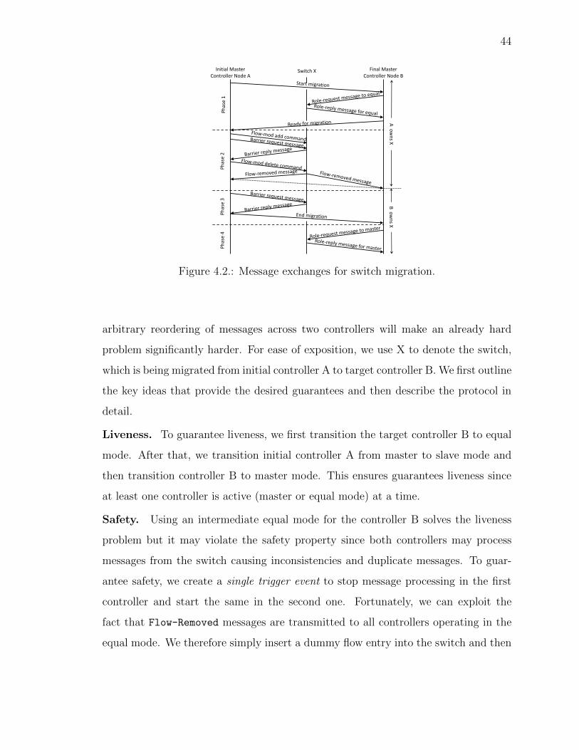
44
Initial Master Controller Node A
Switch X Final Master Controller Node B
Phase 1
Phase 2
Phase 3
Phase 4
A o
wns X
B o
wns X
Figure 4.2.: Message exchanges for switch migration.
arbitrary reordering of messages across two controllers will make an already hard
problem significantly harder. For ease of exposition, we use X to denote the switch,
which is being migrated from initial controller A to target controller B. We first outline
the key ideas that provide the desired guarantees and then describe the protocol in
detail.
Liveness. To guarantee liveness, we first transition the target controller B to equal
mode. After that, we transition initial controller A from master to slave mode and
then transition controller B to master mode. This ensures guarantees liveness since
at least one controller is active (master or equal mode) at a time.
Safety. Using an intermediate equal mode for the controller B solves the liveness
problem but it may violate the safety property since both controllers may process
messages from the switch causing inconsistencies and duplicate messages. To guar-
antee safety, we create a single trigger event to stop message processing in the first
controller and start the same in the second one. Fortunately, we can exploit the
fact that Flow-Removed messages are transmitted to all controllers operating in the
equal mode. We therefore simply insert a dummy flow entry into the switch and then

45
remove the flow entry, which will provide a single Flow-Removed event to both the
controllers to signal hando↵.
Serializability. To guarantee serializability, the controller A should complete pro-
cessing its last message before the controller B can process its first message. However,
the first message for the B may arrive before A completes processing its last message.
So, we cache messages at B until the A has finished processing its last message and
committed it to the switch.
Our protocol operates in four phases described below (shown in Figure 4.2). We
now describe each phase in detail and highlight a trade-o↵ between performance and
serializability.
Phase 1: Change role of the target to equal. In the first phase, target B’s role
is first changed to equal mode for the switch X. Initial master A initiates this phase by
sending a start migration message to B using a proprietary message on the controller-
to-controller channel. B sends Role-Request message to the switch informing that it
is an equal. After B receives a Role-Reply message from the switch, it informs the
initial master A that its role change is completed. After B changes its role to equal,
it receives control messages (e.g., Packet-In) from the switch, but ignores them and
does not respond.
Phase 2: Insert and remove a dummy flow. To determine an exact instant
for the migration, A sends a dummy (but well-known) Flow-Mod command to X to
add a new flow table entry that does not match any incoming packet. Then, it sends
another Flow-Mod command to delete this flow table entry; in response, the switch
sends a Flow-Removed message to both controllers since B is in the equal mode. This
Flow-Removed event signals a hando↵ of switch X from A to B, and henceforth, only
B will process all messages transmitted by switch. Here, our assumption that both
controllers in equal mode receive messages from the switch in the same order is needed
to guarantee the safety property. An additional barrier message is required after the
insertion of the dummy flow and before the dummy flow is deleted to prevent any
chance of processing the delete message before the insert.
46
Although B processes all messages after the Flow-Removed message, it does not
do so immediately. It caches all the messages after the Flow-Removed message and
begins processing them in the next phase. This is needed to guarantee the serializ-
ability property. Processing of messages from the north-bound interface can continue
uninterrupted.
Phase 3: Flush pending requests with a barrier. Now, B has taken over
responsibility of switch X, but A has not detached from X yet. However, it cannot
just detach immediately from the switch since there may be pending requests at A
that arrived before the Flow-Removed message, for which A is still the owner. Con-
troller A processes all messages that arrived before Flow-Removed and transmits their
responses. Then, it transmits a Barrier-Request and waits for the Barrier-Reply.
Receiving a Barrier-Reply from switch X indicates that X has finished processing
all messages that it received before the Barrier-Request messages. So, only after
receiving the Barrier-Reply message, controller A signals “end migration” to the
final master B. The “end migration” message is a signal to B that A has finished pro-
cessing all its messages and committed them to the switch. Once B receives the “end
migration” message, it processes all the cached messages in the order that they were
received. Note that delay in end migration message can potentially cause message
processing latency at B. This delay can be avoided if we do not need to guarantee
serializability. In that case B can start processing Packet-In messages right after
receiving Flow-Removed.
Phase 4: Make target controller final master. Here, A would have already
detached from X and has signaled to B to become the new master, which it does by by
sending a Role-Request message to the switch. It also updates the distributed data
store to indicate this. The switch sets A to slave when it receives the Role-Request
message from the final master B after which it processes all messages from the switch.
Performance-Serializability Trade-o↵. Bu↵ering messages from the switch at
the end of phase 2 is needed to guarantee serializability. It ensures that B be-
gins processing messages only after A has completed processing messages before the

47
Flow-Removed message. The duration for bu↵ering messages will depend on the
network latencies, message loss ratio, controller processing times, etc. In our ex-
periments, we observed that messages were never bu↵ered for more than 50msec.
However, the worst case will depend on many network characteristics and may be
larger. While bu↵ering is needed to guarantee serializability, it has two undesirable
side-e↵ects. First, the controller will be unable to respond to events from the switch
while messages are being bu↵ered. Second, bu↵ered messages will be processed late
and may be irrelevant by the time they are processed. So, the network operator
should choose between two configurations of the migration protocol depending on
network characteristics and application requirements. The ”consistency configura-
tion” bu↵ers messages as described above and provides all three guarantees. The
”performance configuration” does not bu↵er messages. It does not provide serializ-
ability but responds faster to switch events during migration.
4.2.3 Application State Migration
Safety, liveness and serializability guarantees of the migration protocol simplify
controller application changes to support switch migration. The three guarantees
together ensure that applications do not miss any asynchronous events and do not
have to check for duplicate or reordered asynchronous messages from the switch before
processing them. We describe the modifications to the applications and their interface
with the core controller module below. We have implemented them for the routing
applications in ElastiCon.
We added two methods to the interface between the core controller module and
each application module. The first method, named “switch emigrate”, is invoked
at the initial master controller (controller A in the above example). The core con-
troller module invokes this method for each application after it has finished process-
ing all messages before the Flow-Removed message from the switch. The method
returns after the application has flushed all switch-specific state to the distributed

48
Physical)Network)Infrastructure)
Core%Controller%Module%
Applica1on%1% Applica1on%2%
Core%Controller%Module%
Applica1on%1% Applica1on%2%
Distributed%Data%Store%(e.g.,%Hazelcast)%
%%%
Load%Balance%
Scale%Up%Scale%Down%
Ac1ons:%• Migrate%switch%• Remove%controller%• Add%new%controller%
Load%Measurements%
Load%Adapta1on%Decisions%
Distributed%SDN%Controller%
Figure 4.3.: Load adaptation in ElastiCon.
data store. Applications also stop any switch-specific execution (like timers). The
controller sends the “end migration” message only after all applications execute their
“switch emigrate” method. The second method, “switch immigrate”, is invoked at
the target master controller (controller B in the above example) for each applica-
tion. It is invoked after the controller receives the “end migration” message. Each
application reads switch-specific state from the distributed data store to populate
local data structures and starts switch-specific execution. The distributed data store
should guarantee that the controller reads the state written in the “switch emigrate”
method earlier. The controller starts processing cached asynchronous messages after
all applications have executed their “switch immigrate” methods.
State-transfer between applications can also be performed over TCP connections
between applications instead of using the distributed data store. The above design
simplified our implementation since we reused the interface between the application
and the distributed data store. Using this disruption-free migration protocol as a
basic primitive, we now look at load adaptation aspects of ElastiCon.
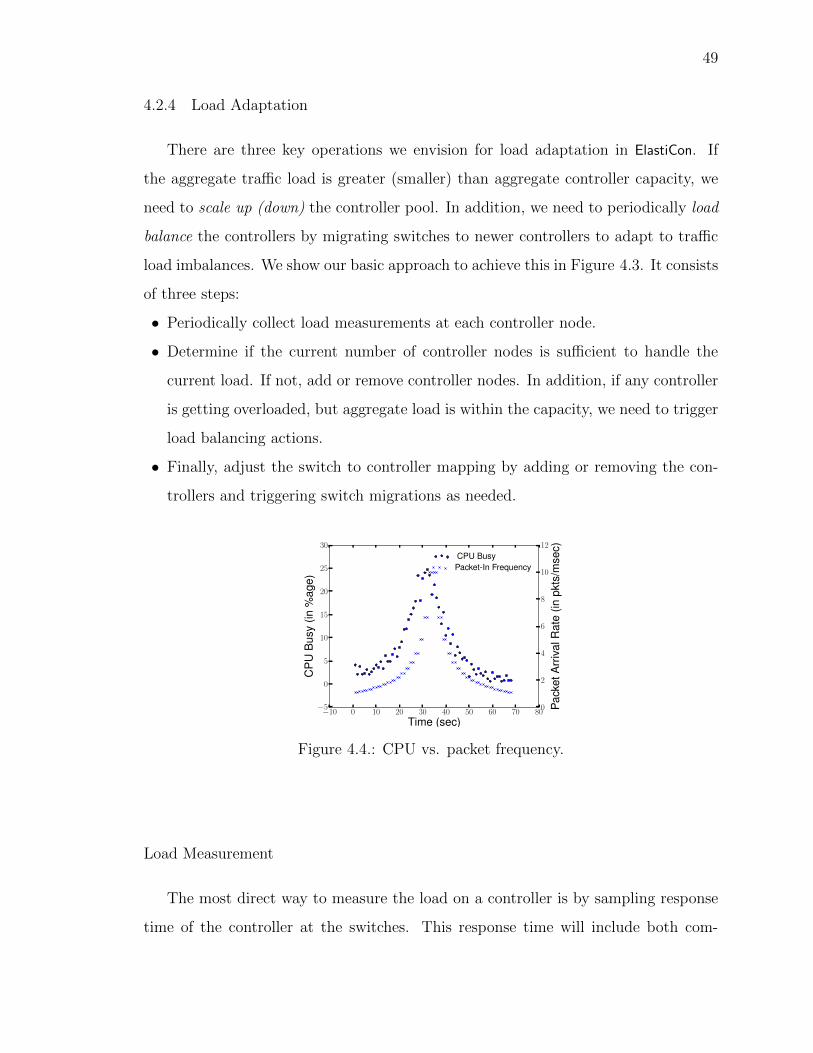
49
4.2.4 Load Adaptation
There are three key operations we envision for load adaptation in ElastiCon. If
the aggregate tra�c load is greater (smaller) than aggregate controller capacity, we
need to scale up (down) the controller pool. In addition, we need to periodically load
balance the controllers by migrating switches to newer controllers to adapt to tra�c
load imbalances. We show our basic approach to achieve this in Figure 4.3. It consists
of three steps:
• Periodically collect load measurements at each controller node.
• Determine if the current number of controller nodes is su�cient to handle the
current load. If not, add or remove controller nodes. In addition, if any controller
is getting overloaded, but aggregate load is within the capacity, we need to trigger
load balancing actions.
• Finally, adjust the switch to controller mapping by adding or removing the con-
trollers and triggering switch migrations as needed.
�10 0 10 20 30 40 50 60 70 80
Time (sec)�5
0
5
10
15
20
25
30
CP
UB
usy
(in%
age)
CPU Busy
0
2
4
6
8
10
12Pa
cket
Arr
ival
Rat
e(in
pkts
/mse
c)Packet-In Frequency
Figure 4.4.: CPU vs. packet frequency.
Load Measurement
The most direct way to measure the load on a controller is by sampling response
time of the controller at the switches. This response time will include both com-

50
putation and network latency. However, switches may not support response time
measurements, since that requires maintaining some amount of extra state at the
switches that may or may not be feasible. Since the controller is more programmable,
ElastiCon maintains a load measurement module on each controller to periodically re-
port the CPU utilization and network I/O rates at the controller. Our experiments
show that the CPU is typically the throughput bottleneck and CPU load is roughly
in proportion to the message rate (see Figure 4.4). The module also reports the aver-
age message arrival rate from each switch connected to the controller. This aids the
load balancer in first dissecting the contribution of each switch to the overall CPU
utilization, and helps making optimal switch to controller mapping decisions. We
assume that the fraction of controller resources used by a switch is proportional to
its fraction of the total messages received at the controller, which is typically true
due to the almost linear relationship between throughput and messages. The load
measurement module averages load estimates over small time intervals (we use three
seconds) to avoid triggering switch migrations due to short-term load spikes.
Algorithm 1 Load Adaptation Algorithm
while True doget inputs()migration set doRebalancing()if migration set == NULL then
if doResizing() thenif checkResizing() then
migration set doRebalancing()else
revertResizing()end if
end ifend ifexecute power on controller()execute migrations(migration set)execute power off controller()sleep(3)
end while

51
Adaptation Decision Computation
The load adaptation algorithm determines if the current distributed controller pool
is su�cient to handle the current network load. It sets a high and low thresholds to
determine whether the distributed controller needs to be scaled up or down. Di↵erence
between these thresholds should be large enough to prevent frequent scale changes.
Then, the algorithm finds an optimal switch to controller mapping constrained by
the controller capacity while minimizing the number of switch migrations. Some
CPU cycles and network bandwidth should also be reserved for switches connected
to a controller in slave mode. Switches in slave mode impose very little load on the
controller typically, but some headroom should be reserved to allow switch migrations.
While one can formulate and solve an optimization problem (e.g., linear program)
that can generate an optimal assignment of switch-to-controller mappings, it is not
clear such formulations are useful for our setting in practice. First, optimal balancing
is not the primary objective as much as performance (e.g., in the form of response
time). Usually, as long as a controller is not too overloaded, there is not much
performance di↵erence between di↵erent CPU utilization values. For example, 10%
and 20% CPU utilization results in almost similar controller response time. Thus,
fine-grained optimization is not critical in practice. Second, optimal balancing may
result in too many migrations that is not desirable. Of course, one can factor this
in the cost function, but then it requires another (artificial) weighting of these two
functions, which then becomes somewhat arbitrary. Finally, optimization problems
are also computationally intensive and since the tra�c changes quickly, the benefits
of the optimized switch-controller mapping are short-lived. So, a computationally
light-weight algorithm that can be run frequently is likely to have at least similar
if not better performance than optimization. Perhaps, this is the main reason why
distributed resource management (DRM) algorithms used in real world for load bal-
ancing cluster workloads by migrating virtual machines (VMs) do not solve any such

52
optimization problems and rely on a more simpler feedback loop [15]. We adopt a
similar approach in our setting.
Our load-adaptation decision process proceeds in two phases, as shown in Al-
gorithm 1. First, during the rebalancing step the load adaptation module evenly
distributes the current load across all available controllers. After rebalancing, if the
load on one or more controllers exceeds the upper (or lower) threshold, the load
adaptation module grows (or shrinks) the controller pool.
Input to the Algorithm. A load adaptation module within ElastiCon periodically
receives inputs from the load measurement module on each controller. The input
contains the total CPU usage by the controller process in MHz. It also contains a
count of the number of packets received from each switch of which that controller is the
master. The packet count is used to estimate the fraction of the load on the controller
due to a particular switch. The load adaptation module stores a moving window of the
past inputs for each controller. We define utilization of a controller as the sum of the
mean and standard deviation of CPU usage over the stored values for that controller.
The rebalancing and resizing algorithms never use instantaneous CPU load. Instead
they use CPU utilization to ensure that they always leave some headroom for temporal
spikes in instantaneous CPU load. Also, the amount of headroom at a controller will
be correlated to the variation in CPU load for that controller.
Output of the Algorithm. After processing the inputs, the load adaptation
module may perform one or more of the following actions: powering o↵ a controller,
powering on a controller, or migrating a switch from one controller to another.
Main Loop of the Algorithm. First, the load adaptation module receives the
inputs from all controllers and augments them to its stored state. All functions except
the execute * functions only modify this stored state and they do not a↵ect the
state of the controllers. After that, the execute * functions determine the changes
to the stored state and send migration and power on/o↵ commands to the appropriate
controllers.
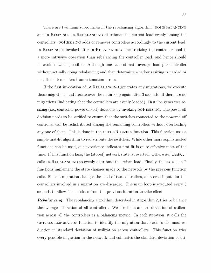
53
There are two main subroutines in the rebalancing algorithm: doRebalancing
and doResizing. doRebalancing distributes the current load evenly among the
controllers. doResizing adds or removes controllers accordingly to the current load.
doResizing is invoked after doRebalancing since resizing the controller pool is
a more intrusive operation than rebalancing the controller load, and hence should
be avoided when possible. Although one can estimate average load per controller
without actually doing rebalancing and then determine whether resizing is needed or
not, this often su↵ers from estimation errors.
If the first invocation of doRebalancing generates any migrations, we execute
those migrations and iterate over the main loop again after 3 seconds. If there are no
migrations (indicating that the controllers are evenly loaded), ElastiCon generates re-
sizing (i.e., controller power on/o↵) decisions by invoking doResizing. The power o↵
decision needs to be verified to ensure that the switches connected to the powered o↵
controller can be redistributed among the remaining controllers without overloading
any one of them. This is done in the checkResizing function. This function uses a
simple first-fit algorithm to redistribute the switches. While other more sophisticated
functions can be used, our experience indicates first-fit is quite e↵ective most of the
time. If this function fails, the (stored) network state is reverted. Otherwise, ElastiCon
calls doRebalancing to evenly distribute the switch load. Finally, the execute *
functions implement the state changes made to the network by the previous function
calls. Since a migration changes the load of two controllers, all stored inputs for the
controllers involved in a migration are discarded. The main loop is executed every 3
seconds to allow for decisions from the previous iteration to take e↵ect.
Rebalancing. The rebalancing algorithm, described in Algorithm 2, tries to balance
the average utilization of all controllers. We use the standard deviation of utiliza-
tion across all the controllers as a balancing metric. In each iteration, it calls the
get best migration function to identify the migration that leads to the most re-
duction in standard deviation of utilization across controllers. This function tries
every possible migration in the network and estimates the standard deviation of uti-
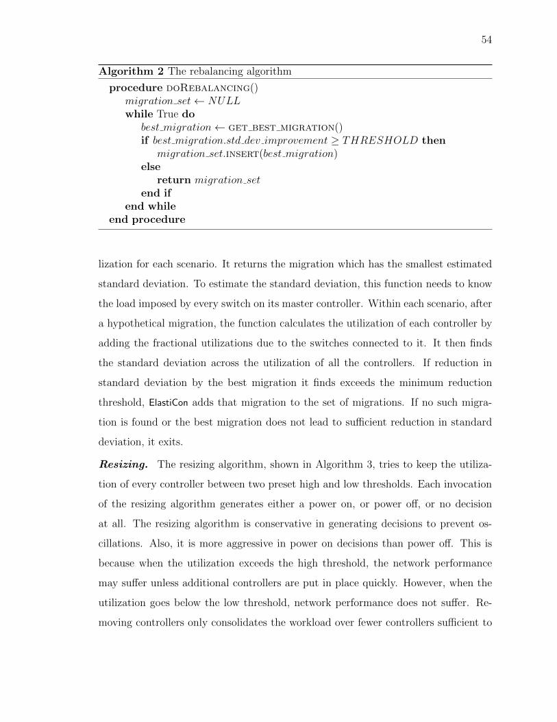
54
Algorithm 2 The rebalancing algorithm
procedure doRebalancing()migration set NULLwhile True do
best migration get best migration()if best migration.std dev improvement � THRESHOLD then
migration set.insert(best migration)else
return migration setend if
end whileend procedure
lization for each scenario. It returns the migration which has the smallest estimated
standard deviation. To estimate the standard deviation, this function needs to know
the load imposed by every switch on its master controller. Within each scenario, after
a hypothetical migration, the function calculates the utilization of each controller by
adding the fractional utilizations due to the switches connected to it. It then finds
the standard deviation across the utilization of all the controllers. If reduction in
standard deviation by the best migration it finds exceeds the minimum reduction
threshold, ElastiCon adds that migration to the set of migrations. If no such migra-
tion is found or the best migration does not lead to su�cient reduction in standard
deviation, it exits.
Resizing. The resizing algorithm, shown in Algorithm 3, tries to keep the utiliza-
tion of every controller between two preset high and low thresholds. Each invocation
of the resizing algorithm generates either a power on, or power o↵, or no decision
at all. The resizing algorithm is conservative in generating decisions to prevent os-
cillations. Also, it is more aggressive in power on decisions than power o↵. This is
because when the utilization exceeds the high threshold, the network performance
may su↵er unless additional controllers are put in place quickly. However, when the
utilization goes below the low threshold, network performance does not su↵er. Re-
moving controllers only consolidates the workload over fewer controllers su�cient to

55
Algorithm 3 The resizing algorithm
procedure doResizing()for all c in controller list do
if c.util � HIGH UTIL THRESH thenswitch on controller()return True
end ifend forcounter 0for all c in controller list do
if c.util LOW UTIL THRESH thencounter counter + 1
end ifend forif counter � 2 then
switch off controller()return True
elsereturn False
end ifend procedure
handle existing tra�c conditions, mainly for power and other secondary concerns
than network performance. Thus, we generate a power on decision when any con-
troller exceeds the high threshold while requiring at least two controllers to fall below
the low threshold for generating a power o↵ decision. Triggering a decision when
just one or two controllers cross the threshold might seem like we aggressively add
or remove controller. But, our decisions are quite conservative because the resizing
algorithm is executed only when the load is evenly distributed across all controllers.
So, if a controller crosses the threshold, it indicates that all controllers are close to
the threshold.
56
Extending Load Adaptation Algorithms
The load adaptation algorithms described above can be easily extended to satisfy
additional requirements or constraints. Here we describe two such potential extensions
to show the broad applicability and flexibility of the algorithm.
Controller Location. To reduce control plane latency, it may be better to assign
a switch to a closeby controller. We can accommodate this requirement in ElastiCon
by contraining migrations and controller additions and removals. To do so, in every
iteration of the rebalancing algorithm (Algorithm 2), we consider only migrations to
controllers close to the switch. This distance can be estimated based on topology
information or controller to switch latency measurements. If the operator wants to
set switch-controller mapping based on physical distance (in number of hops), he/she
can use the network topology. The operator should use latency measurements when
he/she wants to set switch-controller mapping based on logical distance (in millisec-
onds). Similarly, in the resizing algorithm (Algorithm 3), the new controllers added
should be close to the overloaded controllers so that switches can migrate away from
the overloaded controller. The first-fit algorithm used in checkResizing function
should also be modified such that a switch can only “fit” in a closeby controller.
Switch Grouping. Assigning neighboring switches to the same controller may
reduce inter-controller communication during flow setup and hence improve control
plane e�ciency. Graph partitioning algorithms can be used to partition the network
into switch groups; and the result can be fed into ElastiCon. ElastiCon can be modified
to treat each group as a single entity during migration and resizing, so that the
switches of the same group are always controlled by the same controller except for
short intervals during migration. The load measurements module should be modified
to combine load readings of switches of a group and present it as a single entity to
the load adaptation algorithm. When the rebalancing algorithm determines that the
entity needs to be migrated, the execute * functions should migrate all the switches
of the group.

57
Adaptation Action
Following the adaptation decision, adaptation actions are executed to transform
the network configuration (i.e., switch to controller mapping). A switch is migrated
to a former slave by following the steps in our 4-phase migration protocol described
before. In case of controller addition or removal, one or more switches may need
to be reassigned to new master controllers that they are not currently connected to.
This can be done by replacing one of the existing slave controllers’ IP address of the
switch with that of the new controller using the edit-config operation of OpenFlow
Management and Configuration Protocol [48]. Once the connection between the new
controller and the switch is established, we then invoke the migration procedure to
swap the old master with the new slave controller. If a switch does not support
updating controller IP addresses at runtime, other workarounds based on controller
IP address virtualization are also possible (discussed in Section 4.3).
4.3 Implementation
In this section, we present further details on how we implement ElastiCon by mod-
ifying and adding components to the centralized Floodlight controller.
Distributed Data Store. We use Hazelcast to implement the distributed data
store. Although other NoSql databases may have also worked here, we find Hazelcast
a good choice due to its performance and flexibility. Hazelcast provides strong consis-
tency, transaction support, and event notifications. Its in-memory data storage and
distributed architecture ensures both low latency data access and high availability.
Persistent data can be configured to write to disk. It is written in Java, which makes
it easy for integration with Floodlight. We include the Hazelcast libraries in the
Floodlight executable. The first Hazelcast node forms a new distributed data store.
Subsequently, each Hazelcast node is configured with the IP addresses and ports of
several peers. At least one of the peers needs to be active for the new node to join
the distributed data store.
58
Controller. When a controller boots up, it publishes its own local data and retrieves
data of other controllers by accessing Hazelcast. One such data is the IP address and
TCP port of each controller needed for inter-controller communication. This allows
the controllers to set up direct TCP connections with each other, so that they can
invoke each other to set up paths for flows.
The switch to master controller mapping is also stored in Hazelcast using the
unique switch datapath-id as the key. We have modified the core controller in Flood-
light to allow a controller to act in di↵erent roles for di↵erent switches. The initial
switch to master mapping can be determined in one of two ways. In the first method,
the load adapter module running in the controller (described later) reads in the map-
ping from a configuration file and stores the information in Hazelcast. We also imple-
ment an ad hoc strategy by letting the controllers try to acquire a lock in Hazelcast
when a switch connects to them. Only one controller can succeed in acquiring the
lock; it then declares itself as the master for the switch.
Load Adaptation Module. The load measurement module is integrated into
the controller. We use SIGAR API [49] to retrieve the CPU usage of the controller
process. We enhanced the REST API of the controller to include CPU usage queries.
The adaptation decision algorithm run on a separate host. It communicates with all
controllers over the REST API. It requires the REST port and IP address of one of
the controllers. Using that, it queries the controller for the IP address and REST
port of all other controllers and switch-to-controller mappings of all switches in the
network. In each iteration, the program queries the CPU usage information from each
controller and sends migration requests to the master controller of a switch when the
switch needs to be migrated.
Adding and Removing Controllers. Migration of a switch to a newly connected
controller is done in two steps. First, we replace the IP address and TCP port number
of one of the slave controllers of the switch with those of the new controller. This
can be done by using the edit-config operation of OpenFlow Management and
Configuration Protocol [48]. Once the connection between the new controller and the

59
switch is established, we then invoke the migration procedure to swap the old master
with the new slave controller.
Controller C
NAT: IPv <-> IPc
ARP tab: Ipv : MACc
Switch
To MACc, IPv
Figure 4.5.: Controller virtual IP address binding
Controller C’
NAT: IPv <-> Ipc’
ARP
Switch
Controller C
NAT: IPv <-> IPc
1) Install NAT 2) Reset connection 3) Gratitious ARP: IPv – MACc’
4) Reconnect To MACc’, IPv
Figure 4.6.: Controller binding change
If a switch does not support updating controller IP addresses at runtime, we can
use the following procedure as a workaround, which is suitable when the control plane
is configured to use the same layer 2 network (e.g., on the same VLAN). All switches
are configured to use a set of virtual controller IP addresses, which will be mapped to
the real controller IP addresses at runtime according to load condition. Such mapping
can be realized by using ARP and Network Address Translation (NAT), as shown in
Figure 4.5. When the virtual controller IP address ipv
for a switch is mapped to
controller C’s IP address ipc
, we use gratuitous ARP to bind the MAC address of the
controller C with ipv
, so that the packets to ipv
can reach controller C. At controller
C, we do NAT from ipv
to ipc
, so that the packets can be handled by the controller
transparently.
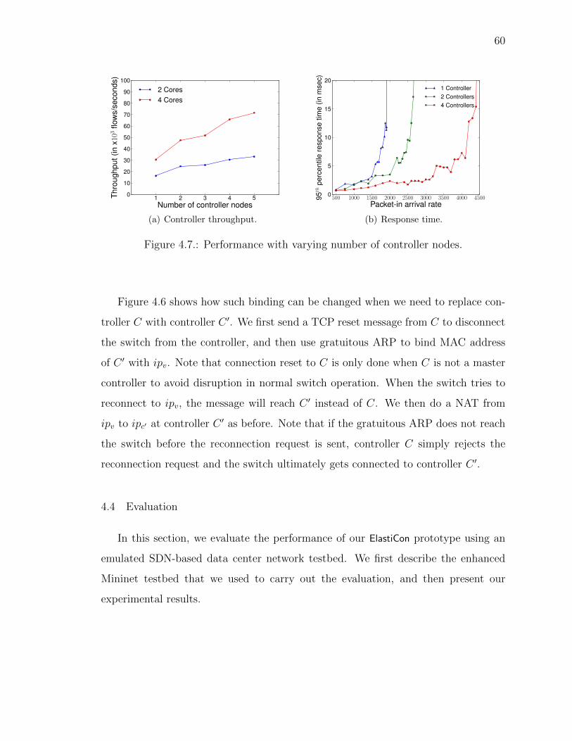
60
1 2 3 4 5Number of controller nodes
0
10
20
30
40
50
60
70
80
90
100
Thro
ughp
ut(in
x103
flow
s/se
cond
s)
2 Cores4 Cores
(a) Controller throughput.
500 1000 1500 2000 2500 3000 3500 4000 4500Packet-in arrival rate
0
5
10
15
20
95th
perc
entil
ere
spon
setim
e(in
mse
c)
1 Controller2 Controllers4 Controllers
(b) Response time.
Figure 4.7.: Performance with varying number of controller nodes.
Figure 4.6 shows how such binding can be changed when we need to replace con-
troller C with controller C 0. We first send a TCP reset message from C to disconnect
the switch from the controller, and then use gratuitous ARP to bind MAC address
of C 0 with ipv
. Note that connection reset to C is only done when C is not a master
controller to avoid disruption in normal switch operation. When the switch tries to
reconnect to ipv
, the message will reach C 0 instead of C. We then do a NAT from
ipv
to ipc
0 at controller C 0 as before. Note that if the gratuitous ARP does not reach
the switch before the reconnection request is sent, controller C simply rejects the
reconnection request and the switch ultimately gets connected to controller C 0.
4.4 Evaluation
In this section, we evaluate the performance of our ElastiCon prototype using an
emulated SDN-based data center network testbed. We first describe the enhanced
Mininet testbed that we used to carry out the evaluation, and then present our
experimental results.
61
4.4.1 Enhanced Mininet Testbed
Our experimental testbed is built on top of Mininet [50], which emulates a net-
work of Open vSwitches [51]. Open vSwitch is a software-based virtual Openflow
switch. It implements the data plane in kernel and the control plane as a user space
process. Mininet has been widely used to demonstrate the functionalities, but not the
performance, of a controller because of the overhead of emulating data flows. First,
actual packets need to be exchanged between the vSwitch instances to emulate packet
flows. Second, a flow arrival resulting in sending a Packet-In to the controller incurs
kernel to user space context switch overhead in the Open vSwitch. From our initial
experiments we observe that these overheads significantly reduce the maximum flow
arrival rate that Mininet can emulate, which in turn slows down the control plane
tra�c generation capability of the testbed. Note that for the evaluation of ElastiCon,
we are primarily concerned with the control plane tra�c load and need not emulate
the high overhead data plane. We achieve this by modifying Open vSwitch to inject
Packet-In messages to the controller without actually transmitting packets on the
data plane. We also log and drop Flow-Mod messages to avoid the additional overhead
of inserting them in the flow table. Although we do not use the data plane during our
experiments, we do not disable it. So, the controller generated messages (like LLDPs,
ARPs) are still transmitted on the emulated network.
In order to experiment with larger networks we deployed multiple hosts to emulate
the testbed. We modified Mininet to run the Open vSwitch instances on di↵erent
hosts. We created GRE tunnels between the hosts running Open vSwitch instances to
emulate links of the data center network. Since we do not actually transmit packets
in the emulated network, the latency/bandwidth characteristics of these GRE tunnels
do not impact our results. They are used only to transmit link-discovery messages
to enable the controllers to construct a network topology. To isolate the switch to
controller tra�c from the emulated data plane of the network, we run Open vSwitch
on hosts with two Ethernet ports. One port of each host is connected to a gigabit

62
Ethernet switch and is used to carry the emulated data plane tra�c. The other port
of each host is connected to the hosts that run the controller. We isolated the inter-
controller tra�c from the controller-switch tra�c too by running the controller on
dual-port hosts.
4.4.2 Experimental Results
We report on the performance of ElastiCon using the routing application. All
experiments are conducted on k=4 fat tree emulated on the testbed. We use 4 hosts
to emulate the entire network. Each host emulates a pod and a core switch. Before
starting the experiment, the emulated end hosts ping each other so that the routing
application can learn the location of all end hosts in the emulated network.
Throughput. We send 10,000 back-to-back Packet-In messages and plot the
throughput of ElastiCon with varying number of controller nodes (Figure 4.7(a)). We
repeat the experiment while pinning the controllers to two cores of the quad-core
server. We observe two trends in the results. First, adding controller nodes increases
the throughput almost linearly. This is because there is no data sharing between
controllers while responding to Packet-In messages. Second, the throughput re-
duces when we restrict the controllers to two cores indicating that CPU is indeed the
bottleneck.
Response time. We plot the response time behavior for Packet-In messages
with changing flow arrival rate (see Figure 4.7(b)). We repeat the experiment while
changing the number of controller nodes. As expected, we observe that response time
increases marginally up to a certain point. Once the packet generation rate exceeds
the capacity of the processor, queuing causes response time to shoot up. This point
is reached at a higher packet-generation rate when ElastiCon has more nodes.
Migration time. The time taken to migrate a switch is critical for the load bal-
ancing protocol to work e�ciently. We define migration time for controller A as the
time between sending the “start migration” message and “end migration” message.
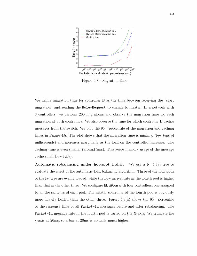
63
10002000
30004000
50006000
70008000
900010000
Packet-in arrival rate (in packets/second)
0
10
20
30
40
50
60
70
80
90
Tim
e(in
mse
c)
Master-to-Slave migration timeSlave-to-Master migration timeCaching time
Figure 4.8.: Migration time
We define migration time for controller B as the time between receiving the “start
migration” and sending the Role-Request to change to master. In a network with
3 controllers, we perform 200 migrations and observe the migration time for each
migration at both controllers. We also observe the time for which controller B caches
messages from the switch. We plot the 95th percentile of the migration and caching
times in Figure 4.8. The plot shows that the migration time is minimal (few tens of
milliseconds) and increases marginally as the load on the controller increases. The
caching time is even smaller (around 5ms). This keeps memory usage of the message
cache small (few KBs).
Automatic rebalancing under hot-spot tra�c. We use a N=4 fat tree to
evaluate the e↵ect of the automatic load balancing algorithm. Three of the four pods
of the fat tree are evenly loaded, while the flow arrival rate in the fourth pod is higher
than that in the other three. We configure ElastiCon with four controllers, one assigned
to all the switches of each pod. The master controller of the fourth pod is obviously
more heavily loaded than the other three. Figure 4.9(a) shows the 95th percentile
of the response time of all Packet-In messages before and after rebalancing. The
Packet-In message rate in the fourth pod is varied on the X-axis. We truncate the
y-axis at 20ms, so a bar at 20ms is actually much higher.

64
55 60 65 70 75 80Hot-spot size (
0
5
10
15
20
95th
perc
entil
ere
spon
setim
e(in
mse
c) Before migrationAfter migration
(a) Single hot-spot tra�c pattern.
0 1 2 3 4 5Seeds
0
5
10
15
20
95th
perc
entil
ere
spon
setim
e(in
mse
c) Before migrationAfter migration
(b) Pareto distributed tra�c pattern.
Figure 4.9.: Benefit of automatic rebalancing. We truncate the y-axis at 20ms, so abar at 20ms is actually much higher.
We observe that as tra�c gets more skewed (i.e., the Packet-In rate in the fourth
pod increases), we see a larger benefit by doing rebalancing corresponding to the 65-
75% bars. At 70-80% hot-spot, the system is unstable. The 95th percentile can
be arbitrarily high depending on the amount of time the experiment is run before
rebalancing, since the one of the controllers is overloaded (i.e., the Packet-In rate
exceeds the saturation throughput). At 80% hot-spot, rebalancing by itself does not
help as seen by the blue bar exceeding 20ms since there is no way to fit the workload
among existing controllers.
Automatic rebalancing under Pareto distribution. We also evaluate the ben-
efit of the rebalancing algorithm in the case where multiple hot spots may appear
randomly following a Pareto distribution. As before, we use a N=4 fat tree with 4
controllers. The network generates 24,000 Packet-In messages per second. The mes-
sage arrival rate is distributed across all the switches in the network using a Pareto
distribution. We repeat the tra�c pattern with 6 di↵erent seeds. We start with a
random assignment of switches to controllers and apply the rebalancing algorithm.
Figure 4.9(b) shows the 95th percentile response time with random assignment and
with rebalancing.

65
Since a Pareto distribution is highly skewed, the improvement varies widely de-
pending on the seed. If the distribution generated by a seed is more skewed, rebal-
ancing is likely to deliver better response times over a random switch to controller
assignment. But, if the Pareto distribution evenly distributes tra�c across switches
(see seeds #2 and #5), random assignment does almost as well as rebalancing. In
the Figure 4.9(b), we can observe that for all cases, rebalancing at least ensures that
there is no controller that is severely overloaded while at least in four cases, random
load balancing led to significant overload as evidenced by the high red bar.
0 2 4 6 8 10 12 14 16 18 20 22 24 26 28 30Time (in minutes)
0
1
2
3
4
5
95th
perc
entil
ere
spon
setim
e(in
mse
c) Controller power-onController power-offResponse time
5
6
7
8
9
10
11
12
Pack
et-In
gene
ratio
nra
te(in
pkts
/mse
c)
Packet-In rate
Figure 4.10.: Growing and shrinking ElastiCon
E↵ect of resizing. We demonstrate how the resizing algorithm adapts the con-
trollers as the number of Packet-In messages increases and decreases. We begin with
a network with 2 controllers and an aggregate Packet-In rate of 8,000 packets per
second. We increase the Packet-In rate in steps of 1,000 packets per second every
3 minutes until it reaches 12,000 packets per second. We then reduce it in steps of
1,000 packets per second every 3 minutes until it comes down to 6,000 packets per
second. At all times, the Packet-In messages are equally distributed across switches,
just for simplicity. We observe 95th percentile of the response time at each minute for
the duration of the experiment. We also note the times at which ElastiCon adds and
removes controllers to adapt to changes in load. The results are shown in Figure 4.10.
66
We observe that ElastiCon adds a controller at the 6th and 10th minute of the ex-
periment as the Packet-In rate rises. It removes controllers at the 22nd and 29th
minute as the tra�c falls. Also, we observe that the response time remains around
2ms for the entire duration of the experiment although the Packet-In rate rises and
falls. Also, ElastiCon adds the controllers at 10,000 and 11,000 Packet-In messages
per second and removes them at 9,000 and 7,000 Packet-In messages per second. As
described earlier, this is because ElastiCon aggressively adds controllers and conserva-
tively removes them.
4.5 Summary
We presented our design of ElastiCon, a distributed elastic SDN controller. We
designed and implemented algorithms for switch migration, controller load balancing
and elasticity which form the core of the controller. We enhanced Mininet and used
it to demonstrate the e�cacy of those algorithms.

67
5 FlowBricks: A FRAMEWORK FOR COMPOSING HETEROGENEOUS SDN
CONTROLLERS
The popularity of SDNs has led to many open-source [42,44,46,47] and proprietary [8]
implementations of SDN controllers. Each controller implementation supports a dif-
ferent set of services and is optimized for di↵erent performance metrics. For example,
Beacon [46] is optimized for latency while Onix [8] provides higher throughput due
to its distributed architecture. Network operators face the onerous task of selecting a
controller implementation that can meet all current and future network services and
performance requirements. In this chapter, we propose a framework, FlowBricks, to
address this problem. It allows network operators to create an SDN control plane by
combining services running on di↵erent controller platforms.
There are four very strong incentives to integrate heterogeneous control planes:
1. Modern networks are intelligent, and require implementation of sophisticated
services such as advanced VPN, deep packet inspection, firewalling, intrusion
detection – to name just a few. Moreover, this list continues to grow, increasing
the need for methods to implement new network policies. However, not all
services may be available on the same controller platform. It is also unlikely that
one controller vendor will have the best-in-class implementation for all services.
Hence, network operators can be forced to choose between not deploying a
service or moving to another controller platform, which is expensive, disruptive,
or even simply infeasible.
2. Even if services can be easily ported from one controller to another, each con-
troller will have di↵erent performance characteristics. Some controllers may
be suitable for high scalability while others may have low response times. In
such cases, it may be desirable to run di↵erent services on di↵erent controllers to
68
match the controller performance characteristics with service requirements. For
instance, services which reactively insert flow table entries to route flows need
low response times and services which passively sample packets in the network
might need to scale to keep up with network tra�c load.
3. Some services may not require global network knowledge and may benefit from
proximity to the data plane. Such services can be implemented on a controller
platform in the network element itself while others can be implemented on the
centralized controller. As we show later, FlowBricks can also be deployed on the
every switch combine switch-local and centralized services.
4. In traditional networks, new network functionality can be implemented through
middleboxes that support integration of services in a “bump-in-the-wire” man-
ner (e.g., firewalls) [52]. Though middleboxes are transparent to existing ser-
vices, in the long run, network operators prefer to integrate services supported
by middleboxes into routers and switches in order to reuse existing hardware
accelerators for packet processing and significantly reduce power and space de-
mands. As a result, network management can be simplified and become less
expensive, thus further motivating new abstractions that enable composition of
services from heterogeneous controllers.
Thus, network operators are in need of constructors for flexible implementation of
policies (that consist of services from various controller vendors, ideally, transparently
to the services of integrated controllers) which allow for flexible and sound assemblage.
Standardizing the northbound and east-west interfaces to the controller is a tech-
nically feasible but impractical approach to combine services running on di↵erent
controllers. In this paper, we show that a standardized southbound API is su�cient
to combine services. We demonstrate this using OpenFlow as an example. While
doing so, we found that the southbound API needs to convey certain information
explicitly and specify certain switch behavior which OpenFlow does not. We describe

69
these stipulations later which are essentially the properties of a southbound API that
are needed for correctly implementing FlowBricks.
Previous research has tackled two types of service composition: parallel and se-
rial. Parallel composition gives the illusion that each service operates on its own copy
of the packet. Then, a set union of modifications from all services is applied to the
packet. In the serial case, services operate on a packet in sequence. So, each service
operates on a packet that has already been modified by prior services. Frenetic [53]
does parallel composition of services while Pyretic [28] supports both serial and par-
allel composition. However, both assume that all services are running on the same
controller. Flowvisor [54] slices the network and flows and assigns each slice to a
di↵erent controller. It supports heterogeneous controllers but does not allow apply-
ing services from di↵erent controllers on the same tra�c. [55] describes the design
of an SDN hypervisor that is capable of combining services from heterogeneous SDN
controllers similar to FlowBricks. However, their technique for composing forward-
ing table rules has two undesirable consequences. First, it leads to an exponential
increase in number of forwarding rules in the datapath which makes their solution
infeasible for switches with limited TCAM space. Second, it does not allow demulti-
plexing of northbound control plane messages. Hence, the SDN hypervisor will have
to broadcast northbound OpenFlow messages (like Packet-In messages) to all con-
trollers which can lead to incorrect behavior. The core contribution of this paper is
a new framework named FlowBricks for integrating services from heterogeneous SDN
controllers. The paper is organized as follows:
• We present our complete design of FlowBricks (Section 5.2). This includes the
architecture of FlowBricks, policy definitions and algorithms for combining flow
tables and other OpenFlow features from heterogeneous SDN controllers.
• We point out requirements in OpenFlow that impact the realization of FlowBricks
(Section 5.3).
• FlowBricks introduces two performance overheads. First, it introduces additional
flow table lookups for every packet on the datapath. Second, routing every mes-
70
sage through FlowBricks may impact throughput and latency of the control plane.
We describe techniques to reduce the impact of FlowBricks on control plane and
data plane performance(Section 5.4).
• We describe our experiments with FlowBricks involving 20 di↵erent combinations of
five services implemented on four di↵erent controllers. We experimentally evaluate
the technique to mitigate the impact of FlowBricks on control plane performance.
(Section 5.5).
We begin with a brief review of OpenFlow terminology and switch forwarding
behavior (Section 5.1).
5.1 Background: Packet Forwarding in OpenFlow
In this section, we recall terminology, switch components and forwarding behavior
specified by OpenFlow 1.1 [56]. In short, a switch consists of flow tables and an action
set.
Flow Entry. Each flow table contains one of more flow entries. Each flow entry
contains a set of match fields for matching packets, a priority, and a set of instructions.
When a packet hits a flow table, it is matched with all the flow entries in the table
and exactly one is selected (if the packet matches multiple flow entries, the one with
the highest priority is selected). Then, the instructions in the instruction set of that
flow entry are executed. A controller may associate an idle timeout interval and a
hard timeout interval with each flow entry. If no packet has matched the flow entry
in the last idle timeout interval, or the hard timeout interval has elapsed since the
flow entry was inserted, the switch removes the entry.
Instructions. An instruction results in changes to the packet, action set and/or
pipeline processing. The Apply-Actions instruction contains a list of actions which are
immediately applied to the packet being processed. The Write-Actions instruction
contains a list of actions which are inserted into the action set and the Clear-Actions
instruction removes all actions from the action set. The Goto-Table instruction indi-
71
cates the next table in the pipeline processing. When a packet matches a flow entry,
the instructions in the instruction set of that flow entry are executed.
Actions. An action describes packet handling. This includes forwarding a packet to
a specific output port, pushing or popping tags, and modifying packet header fields.
Action Set. A set of actions are applied to a packet after all flow table processing
has been completed. Being a set, the action set cannot contain more than one action
of each type. A flow entry can populate the action set with the Write-Actions
instruction and clear it with the Clear-Actions instruction.
Group Table. A group table consists of group entries which are identified by
a unique 32-bit identifier. A group entry specifies more complex forwarding like
flooding, multicast and link aggregation. Flow table entries can point a packet to a
group entry using the Group action and its unique group entry identifier.
The OpenFlow pipeline processing for a packet starts at flow table 0. The packet
is matched against the flow entries of flow table 0 to select a flow entry. Then, the
instruction set associated with that flow entry is executed. If the instruction set
contains a Goto-Table instruction, the packet is directed to another flow table and
the same process is repeated. If the instruction set does not contain a Goto-Table
instruction, pipeline processing stops and the actions in the action set are applied to
the packet.
5.2 FlowBricks Design
To restate, FlowBricks aims to serially concatenate both proactive and reactive
services from heterogeneous controllers onto the same tra�c. In this section, we first
describe the high-level system architecture. We then show how policies are defined
in FlowBricks and describe a technique to combine flow table pipelines of controllers
to realize these policies.
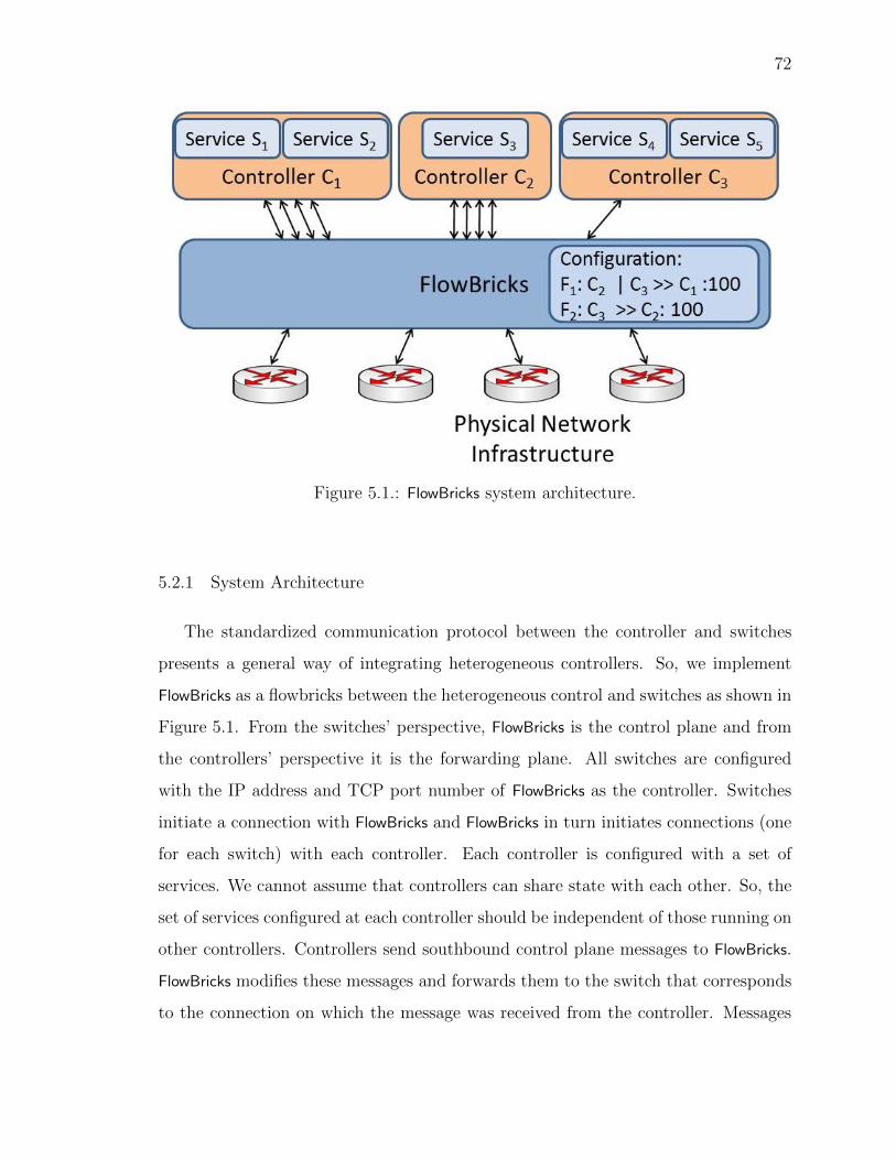
72
Figure 5.1.: FlowBricks system architecture.
5.2.1 System Architecture
The standardized communication protocol between the controller and switches
presents a general way of integrating heterogeneous controllers. So, we implement
FlowBricks as a flowbricks between the heterogeneous control and switches as shown in
Figure 5.1. From the switches’ perspective, FlowBricks is the control plane and from
the controllers’ perspective it is the forwarding plane. All switches are configured
with the IP address and TCP port number of FlowBricks as the controller. Switches
initiate a connection with FlowBricks and FlowBricks in turn initiates connections (one
for each switch) with each controller. Each controller is configured with a set of
services. We cannot assume that controllers can share state with each other. So, the
set of services configured at each controller should be independent of those running on
other controllers. Controllers send southbound control plane messages to FlowBricks.
FlowBricks modifies these messages and forwards them to the switch that corresponds
to the connection on which the message was received from the controller. Messages

73
from the controllers to switches are modified such that the datapath configured on
the switches combines the services from all controllers. The services are combined
according to a policy configured in FlowBricks by the network operator. Northbound
control plane messages from switches are forwarded by FlowBricks to one or more
controllers using internal state and fields in the message (more details later).
5.2.2 Policy Definition
The policy configured on FlowBricks specifies how services from controllers are ap-
plied to tra�c on the datapath. We use the | and >> operators for parallel and serial
composition of heterogeneous controllers in a policy. These are similar to syntactic
elements used in Pyretic for composing services (for a single controller).
The policy is specified on a per flow1 basis. A policy is described by a flow, an
ordered set of controllers whose services should be applied to that flow and a priority.
The policy is configured in FlowBricks and the controllers themselves are unaware of
the policy. For instance, three controllers C1, C2, C3 may be composed as follows:
F1 : C1|C2>>C3 : 100 (5.1)
F2 : C2>>C1 : 99 (5.2)
This describes FlowBricks’s policy for two flows, F1 and F2. FlowBricks applies
services of C1, C2 and C3 to packets of flow F1 in that sequence. It applies services
of C2 and C1 to packets of flow F2 in sequence. F1 has a priority of 100 while F2 has
priority 99. A higher number indicates a higher priority. So, packets which match
both flow definitions will be treated as F1’s packets. Controllers can be concatenated
in two ways. A network operator may want to specify that a controller’s flow tables
should complete all their processing and apply actions (modifications) to the packet
before the packet is processed by the next controller’s flow tables. This is serial
1A flow can be defined on any fields of the packet header. For instance, a flow can be defined aspackets with the same VLAN tag or packets destined for the same subnet.

74
composition of controllers and is represented as >>. Otherwise, the operator may
wish to forward the packet to the flow tables of the next controller without applying
the actions of the previous controller. This is parallel composition and is represented
by |. During parallel composition, the actions generated by a controller’s flow tables
are added to an action set and the unmodified packet is matched with the following
controller’s flow tables. This accumalation of actions in the action set continues until
reaching the end of the policy or a serial composition operator in the policy. At this
point, the actions accumulated in the action set are applied to the packet.
The serial and parallel composition operators are an intuitive and powerful way to
compose services, as shown in [28]. For example, consider a network administrator
who wants to deploy tra�c monitoring, network address translation (NAT), and rout-
ing services implemented on three di↵erent controllers (C1, C2, and C3 respectively) for
all HTTP tra�c. The tra�c monitoring service and NAT should see the unmodified
packets while the routing service should be applied to packets after their addresses
have been modified by NAT. One way to achieve this using the serial and parallel
composition operators is shown in the equation below:
http : C1|C2>>C3 : 100 (5.3)
In this policy, C1 (tra�c monitoring) and C2 (NAT) are composed with the parallel
composition operator (|). The umodified packet will be matched with their flow tables
and the actions will be stored in an action set. Then, these actions will be applied
to the packet for serial composition (>>) before the packet is matched with C3’s flow
tables.
5.2.3 Constraints on Combining Flow Table Pipelines
Controllers C1, C2 and C3 use a sequence of messages to install their flow table
pipelines on the switch. FlowBricks modifies these messages such that a combined flow
table pipeline is installed on the switch. The combined flow table pipeline should

75
apply the services of controllers to packets according to the policy configured by the
network operator. Creating a combined flow table pipeline involves linking flow tables
from di↵erent controllers or combining flow entries from controllers’ flow tables into a
single flow table. This can be done in many ways. In this section, outline constraints
which have to be met by any technique for correctly combining flow table pipelines.
a. Combining flow table entries: One way to combine two flow tables into a single
flow table involves computing the cross product of the flow tables [57]. Pyretic
uses this technique to combine flow tables from di↵erent services. However,
flow table entries may have configurations like counters or idle timeout. It
is impossible to assign a correct idle timeout to a flow table entry obtained
by combining two flow table entries with di↵erent idle timeouts. In the most
general case, each controller may assign di↵erent idle timeout values to its flow
table entries. This would prevent FlowBricks from computing the cross product
of flow tables.
b. Duplicating flow table entries: Some techniques to combine flow tables may
require that each flow in the policy have its own set of flow tables. For instance,
consider the policy in 5.1 and 5.2. Packets of F1 may be processed by flow
tables 1 to 4 in the combined pipeline while packets of F2 may be processed by
flow tables 5 to 7. This would require duplicating flow table entries of C1 and C2
since they should be matched against packets of both flows. However, this would
lead to incorrect behavior for flow table entries that have idle timeouts. If a
controller’s flow table entry with an idle timeout is duplicated by FlowBricks and
inserted into two flow tables on the switch by FlowBricks, one copy of the flow
table entry may be removed due to the idle timeout while the other remains.
This may lead to unexpected switch behavior from the controller’s perspective
since packets of one flow continue to be matched against a flow table entry while
the packets of another flow don’t.

76
c. Modifying flow table pipeline: FlowBricks may need to modify the combined
flow table pipeline on the switch when the administrator changes the policy.
However, this change should not require moving a controller’s flow table entry
from one flow table to another. Doing so would reset the idle timer in the
switch leading to wrong behavior. Similarly, if a controller adds or removes a
flow table entry, FlowBricks should not add or remove the flow table entries of
other controllers.
d. Forwarding Packet-In messages: A switch can send a packet from the data-
path to the controller using a Packet-In message. When FlowBricks receives
a Packet-In message from the switch, it needs to forward the message to the
controller whose flow table entry generated that Packet-In message. FlowBricks
needs to identify this controller using just the fields in the Packet-In message.
The Packet-In message has a table-id field which holds the table-id of the flow
table entry which generated the Packet-In message. To use the table-id field
for forwarding Packet-In messages, FlowBricks should not insert flow table en-
tries of di↵erent controllers into the same flow table on the switch. To rephrase,
each flow table on the switch should contain flow table entries from just one
controller to enable demultiplexing of Packet-In messages to controllers using
table-id.
We now propose a technique to combine flow table pipelines which obeys the above
constraints.
5.2.4 Combining Flow Table Pipelines
In this section, we describe a technique to combine flow table pipelines which
obeys the above constraints. Figure 5.2 shows the flow table pipeline obtained by
combining the flow table pipelines of C1, C2 and C3 using this technique. The combined
flow table pipeline contains flow tables from all controllers. In addition, the pipeline
contains one flow table (which we call transitional flow table) for each controller. The

77
F1
F2
T-C1 F1
F2
T-C2 F1
T-C3
F1
F2
Flow Table #0
C1 Flow Tables C2 Flow Tables
End of pipeline execution
C3 Flow Tables
Start of pipeline execution
Figure 5.2.: Pipeline configured on switch by FlowBricks
transitional flow table directs pipeline execution in the desired sequence between the
controllers’ flow tables. Transitional flow tables are labeled T-C1, T-C2 and T-C3 in
the figure. FlowBricks modifies each controller’s flow tables to ensure that pipeline
processing proceeds from a controller’s flow tables to its transitional flow table. Each
transitional flow table contains one flow table entry for every flow in the policy. The
flow table entry directs pipeline execution to the flow tables of the next controller in
the policy for that flow.
An Example
Figure 5.2 shows the combined flow table pipeline for the policy in equations 5.1
and 5.2. Assume a packet belonging to F1 arrives at the switch. Flow table pipeline
78
processing for the packet begins at flow table 0. The packet will match the flow table
entry for F1 in flow table 0. This flow table entry directs execution to C1’s flow tables
since it is the first controller in F1’s policy. After the packet has been processed by
C1’s flow table, it proceeds to T-C1. The entry for F1 in T-C1 directs execution to C2’s
flow table. From there execution for F1’s packets proceeds to T-C2, then to C3’s flow
tables and finally to T-C3. The flow table entry for F1 in T-C3 terminates pipeline
execution since C3 is the last controller in F1’s policy. For packet belonging to F2,
pipeline execution also begins at flow table 0. But, F2’s packets will match F2’s flow
table entry in flow table 0. This entry directs execution to C2’s flow tables. From
there, execution for F2’s packets proceeds to T-C2, then C1’s flow tables and finally to
T-C1.
Flow table number map
Each controller inserts its flow table entries into flow tables which are numbered
starting with 0. If FlowBricks forwards messages from the controller to the switch
without modification, a flow table on the switch may contain flow table entries from
multiple controllers. But, each controller should have its own set of flow tables in
the combined flow table pipeline. To achieve this, FlowBricks needs to map each
controller’s flow tables onto unique flow tables on the switch. For this, FlowBricks
maintains a flow table number map. This data structure maps the controller-id, flow
table number pair to a unique flow table number on the switch. When FlowBricks
receives a message containing a ”flow table number” field from the controller, it does
a lookup on the flow table number map and replaces the controller’s flow table number
with the unique flow table number before forwarding the message to the switch. A
message from the switch to FlowBricks may also contain a flow table number field. In
such a message, FlowBricks needs to replace the flow table number with the controller’s
flow table number. For this it does a reverse lookup on the flow table number map
using the flow table number in the message. This lookup returns a controller-id

79
and the controller’s flow table number. FlowBricks inserts the controller’s flow table
number in the message and forwards the message to that controller.
Transitional flow tables
We now describe how FlowBricks determines instructions, match fields and priority
of the flow entries in transitional flow tables.
Instructions. Flow entries in a controller’s flow tables contain instructions to add
actions to the action set while leaving the packet unmodified. The flow table entries
in a transitional flow table contain di↵erent instructions depending upon whether
they direct execution across a serial or parallel composition operator. Transitional
flow table entries that direct execution across a parallel composition operator contain
a Goto-Table instruction to direct execution to the following controller’s flow tables.
For example, the entry for F1 in T-C1 will contain a Goto-Table instruction to C2’s
first flow table. This way, the packet remains unmodified and the actions generated
by the following controller’s (C2 in this case) flow tables are also added to the action
set.
Transitional flow table entries that direct execution across a serial composition
operator contain an instruction to apply all the actions accumalated in the action
set along with a Goto-Table instruction. For example, the flow entry for F1 in T-C2
will direct execution across a serial composition operator. So, it will contain an
instruction to apply the actions in the actions set. At that point, the action set will
contain actions inserted by C1 and C2’s flow tables entries. F1’s flow table entry in
T-C2 will also contain a Goto-Table instruction to direct pipeline execution to C3’s
first flow table.
Matching Packets. Flows in FlowBricks’s policy are defined using fields of the
packet header. However, the fields in the packet header may be modified by flow
table entries. So, to identify the flow for a packet, we cannot match the fields in

80
the packet header. We illustrate the problem with an example. Let F3 be defined as
packets with destination IP address X. The policy for F3 is shown below.
F3 : C1>>C2>>C3 : 98 (5.4)
Assume that C1’s flow table entries rewrite the destination IP address. The IP address
modifications will be applied to the packet at the serial composition operator between
C1 and C2. So, the flow table entry in the transitional flow tables following C2 cannot
identify F3’s packets by matching the destination IP address with X.
To work around this problem, we use the metadata field of a packet. OpenFlow
associates a metadata with every packet being processed in the flow table pipeline. It
also provides instructions to modify the bits in the metadata. The match for a packet
in a flow table entry can also include bits of the metadata. FlowBricks generates a
unique identifier for every flow in the policy. The flow table entries in the first flow
table (flow table #0) of the pipeline match packets with the fields in the packet
header. This is not a problem since the packet has not yet been modified. These flow
table entries also write the unique flow identifier into the packet’s metadata field.
Flow table entries in subsequent transitional flow tables match a packet with the
metadata rather than the packet header fields.
Priority. The policy definition in FlowBricks assigns a priority to each flow. FlowBricks
assigns the same priority to the corressponding flow table entry in the transitional
flow table. For instance, F1’s entry in T-C1, T-C2 and T-C3 will have priority 100, since
that was F1’s priority in equation 5.1.
Group Tables
Controllers may insert group entries into the group table. Each group entry is
identified by a unique group identifier. Like the flow table number map, FlowBricks
maintains a mapping from each controller’s group identifiers to globally unique group
identifiers. For southbound messages, FlowBricks replaces the controller’s group iden-

81
tifier with a globally unique group identifier by doing a lookup on this map. This
replacement is done for all messages that contain a group identifier. This includes
messages that modify the group table and messages that contain the Group action
which requests packet processing through a specified group. For northbound mes-
sages, it performs the reverse operation using reverse-lookup on the same map.
Handling Policy Updates
The networks administrator may update the policy configured in FlowBricks at any
time. This may involve adding/removing a flow to the policy, changing the processing
for an exisiting flow or add/removing a controller. All these update involve changes to
only the transitional flow tables. However, these changes need to be done atomically
to avoid incorrect packet processing during update. For switch-local changes, updates
can be done atomically using the Bundle messages introduced in OpenFlow 1.4 [58].
Mechanisms proposed in [59] can be used for updates that span multiple switches.
5.2.5 OpenFlow Message Processing
In this section, we describe message processing for some common OpenFlow mes-
sages. The processing of other messages usually involves just translation of flow table
numbers.
Flow-Mod Messages. OpenFlow uses a Flow-Mod message to insert a flow table
entry in a switch. The Flow-Mod message contains the number of the flow table where
the flow table entry should be inserted. FlowBricks modifies the flow table number
using the flow table number map described in Section 5.2.4. A Flow-Mod message
also contains a list of instructions which are executed when a packet matches the
flow table entry. The absence of a Goto-Table instruction from the instruction list
of a Flow-Mod message indicates that the controller expects pipeline processing to
terminate at that flow table entry. For such flow table entries, FlowBricks inserts a
Goto-Table instruction to direct pipeline execution to a transitional flow table.
82
Packet-In Messages. When a packet does not match any flow table entry, the
switch generates a Packet-In message to the controller. A controller can configure
the number of bytes in the Packet-In message and bu↵ering for the packet in one
of two ways. The controller can request the switch to bu↵er the packet and send a
fixed number of bytes of the packet in the Packet-In message. Otherwise, it can
request the switch to send the entire packet in the Packet-In. FlowBricks configures
the switch to bu↵er the packet and send a fixed number of bytes of the packet in the
Packet-In message. To handle controllers that have requested the entire packet in
the Packet-In message, FlowBricks sets the fixed number of bytes in the Packet-In
message equal to the maximum transmission unit (MTU) of the network.
The Packet-In message also contains a flow table number. This is the flow table
number of the flow entry that generated the Packet-In message. Using the flow
table number, FlowBricks performs a reverse lookup on the controller to switch flow
table map. It replaces the flow table number in the Packet-In message with the con-
troller’s flow table number and forwards the Packet-In message to the corresponding
controller (i.e. the controller which inserted flow table entries into that flow table).
Packet-Out Messages. A Packet-Out message may contain the entire packet or a
bu↵er identifier where the packet is stored. In either case, the FlowBricks just forwards
the packet to the switch without modification.
Barrier and Statistics Messages. FlowBricks forwards barrier and statistics re-
quest message from the controller to the switch and their replies in the reverse di-
rection. The transaction ID field of the request messages need to be unique. Since
the transaction ID field of the request messages is populated by the controller, two
controllers may send a request message with the same transaction ID to the same
switch. To avoid this problem, FlowBricks replaces the transaction ID in the request
messages with a unique value before forwarding it to the switch and does the reverse
operation for the replies. This ensures uniqueness of the transaction ID field in a
manner that is transparent to the controllers.

83
5.3 OpenFlow Limitations
We also point out stipulations in OpenFlow 1.3 which impede implementation of
FlowBricks using the flow table concatenation algorithm described earlier. For ease
of exposition, we assume that FlowBricks is configured with flows shown in eqs. (5.1)
and (5.2).
Packet Drops. OpenFlow does not have an explicit action to drop packets. Open-
Flow specifies an Output action that takes an output port as parameter. At the
end of pipeline execution, if the action set contains the Output action, the packet is
transmitted on that output port. Otherwise, the packet is dropped. Any flow entry
can force a packet drop by clearing the action set and terminating pipeline execu-
tion. Consider F1 in Equation 5.1. C1 can never drop a packet since FlowBricks will
not let pipeline execution terminate at any of C1’s flow tables. It will always add a
Goto-Table instruction to C1 flow entries to continue execution to T-C1.
A simple way to get around this problem is to introduce a Drop action in the
OpenFlow specification. Flow table entries that want to drop a packet, should insert
the Drop action into the action set. If the action set contains a drop action when it
is applied to the packet, the packet is dropped. Otherwise, it is sent on the output
port specified by the Output action.
When FlowBricks sees an instruction to insert a Drop action in a flow table entry, it
can deduce that the flow table entry wants to drop the packet. So, FlowBricks should
not insert a Goto-Table instruction in that flow table entry. This will terminate
pipeline execution without processing flow tables from subsequent controllers.
Executing Action Set. The action set is executed after pipeline processing has
finished. However, if policy definition contains a serial composition operator between
two controllers (between C2 and C3 for F1), then the switch should apply the actions
in the action set after the packet has finished matching the flow tables of controllers
before the serial composition operator. Currently, there is no way of doing this in
OpenFlow.

84
This problem is addressed by introducing an Execute-Actions instruction. This
instruction executes all the actions stored in the action set and clear the action set.
FlowBricks inserts this instruction in those entries of the transitional flow tables which
direct execution across a serial composition operator in the policy definition.
Sequence of Flow Tables. Switch flow table numbers start with 0. OpenFlow
states that packet processing cannot go from a higher flow table number to a lower one.
This limits the possible rules that can be composed in FlowBricks. For instance, it is
impossible to simultaneously implement F1 and F2 ( eqs. (5.1) and (5.2)) in FlowBricks.
If C1’s flow tables have lower flow table numbers than those of C2, then, F2’s policy
cannot be configured on the switch since it will involve going from a higher to lower
flow table number. Similarly, if C1’s flow tables have higher flow table numbers than
those of C2, F1’s policy cannot be configured on the switch.
As a simple workaround, FlowBricks could duplicate flow tables of C1’s flow tables.
One set of C1’s flow tables could have lower flow table numbers than those of C2’s.
Another set could have higher flow table numbers than C2. However, this workaround
is infeasible if C1’s flow table entries have soft timeout interval. OpenFlow specifies
that a flow table entry will time out and be removed from the flow table when no
packet matches the flow table entry for a pre-configured soft timeout interval. If we
duplicate C1’s flow table entries, one set of entries may soft timeout and be removed
while the other set continues to match packets. This would leave the switch in an
inconsistent state.
Parallel Compostion Limitations. Consider a policy that composes two con-
trollers in parallel: C1 | C2. C1 and C2’s flow tables should add actions to the action set
and these actions should be applied to the packet at the end of the pipeline. There
are two potential problems with this. First, OpenFlow allows flow table entries to
directly apply actions to packets (without adding them to the action set) using the
Apply-Actions instruction. If C1’s flow table entries use the Apply-Actions instruc-
tion, C2’s flow tables will be matched with the modified packet which violates parallel
composition. Second, C2’s flow tables may use the Clear-Actions instruction to re-

85
move actions inserted in the action set by C1. Both these errors can be reported by
FlowBricks using simple checks. In some cases, the network operator could reorder the
controllers in the policy to achieve the desired behavior. For instance, the policy C2 |
C1 will work correctly if C1 uses Apply-Actions and C2 uses Clear-Actions.
5.4 Performance Considerations
The ability to compose a SDN control plane from heterogeneous controllers comes
at a cost. FlowBricks inserts transitional flow tables into the flow table pipeline which
adds flow table lookups to packet processing. The latency between the controller and
switches increases since message need to routed via FlowBricks. We propose ways to
mitigate these overheads introduced by FlowBricks.
5.4.1 Reducing Number of Flow Table Lookups
The number of flow table lookup operations required for packet processing deter-
mines the line rate that the switch can support. FlowBricks adds one flow table lookup
in the transitional flow table per controller. This reduces the line rate supported by
the switch. [60,61] propose techniques e�ciently to reduce the number of lookups at
the expense of TCAM space. However, these techniques cannot be directly applied
in FlowBricks due to constraints introduced by idle timeouts and counters associated
with flow table entries. Here, we propose computing the cross product of two sets of
flow table entries to avoid an lookups in transitional flow tables. This is similar to the
technique used by Pyretic to combine policies but is applied selectively to flow table
entries that do not have idle timeouts or counters associated with them. We first
describe the technique with an example and then outline the algorithm to implement
the technique.
86
Example
Figure 5.3 shows unmodified C1 flow tables on the left and C1 flow tables after
taking cross product with T-C1 on the right. Initially, C1 has two flow tables with
two flow table entries each. Assume that flow table entry for FD
has an idle timeout.
To avoid the flow table lookup for T-C1, we iterate over (pi
, qj
) 2 P ⇥ Q where P is
the set of flow table entries in T-C1 and Q is the set of flow table entries in C1’s flow
tables that contain Goto-Table instructions to T-C1 and do not have idle timeouts
or counters associated with them. In Figure 5.3, P = {F1, F2} and Q = {FA
, FC
}.
For each (pi
, qj
), generate a flow table entry by computing the intersection of the
flow patterns, sum of the priorities and union of the instruction sets. Insert this new
flow table entry in qj
’s flow table. The resulting flow tables will avoid the additional
lookup in T-C1 for packets of flows FA
and FC
as shown on the right side in Figure 5.3.
Algorithm
A controller sends a Flow-Mod message to insert or delete a flow table entry. To
configure the modified flow table pipeline on the switch, FlowBricks needs to processes
Flow-Mod messages di↵erently. We first describe how FlowBricks processes Flow-Mod
messages that insert a flow table entry.
a. When FlowBricks receives a Flow-Mod message from a controller to add a flow ta-
ble entry, it processes the message as described in Section 5.2.5. If FlowBricks did
not add a Goto-Table instruction to direct pipeline execution to a transitional
flow table, then processing of the Flow-Mod messages stops and the message is
sent to the switch. If the Goto-Table instruction was added the following steps
are executed.
b. FlowBricks checks if the flow table entry being inserted by the Flow-Mod message
has an idle timeout or counters associated with it. If it does, then the additional

87
Figure 5.3.: C1 flow tables before and after computing cross product with T-C1.
lookup in the transitional flow table cannot be avoided for packets that match
this flow table entry. FlowBricks skips the following steps and forwards the
Flow-Mod message to the switch.
c. FlowBricks removes the Goto-Table instruction from the flow table entry. Then,
FlowBricks iterates over every entry in the transitional flow table of the controller
that sent the Flow-Mod message. For each entry in the transitional flow table,
FlowBricks generates a new flow table entry by intersecting the flow pattern,
summing the priority and computing the union of the instruction set with the
Flow-Mod message. If the transitional flow table has n flow table entries, the
above iteration will generate n Flow-Mod messages. If the original flow table

88
entry had a hard timeout, configure the same hard timeout to all n flow table
entries generated by taking the intersection with the transitional flow table.
Finally, all n Flow-Mod messages are encapsulated in a Bundle message to ensure
that they are applied atomically on the switch.
Note that we do not violate any of the constraints in Section 5.2.3. We only
combine a controller’s flow table entries with its transitional flow table entries for
those entries that do not have idle timeouts and counters. Also, each flow table on
the switch will still contain just one controller’s flow table entries since P and Q never
contain flow table entries from two di↵erent controllers.
Avoiding the additional lookup comes at the cost of increase in number of flow
table entries. For example, consider a transitional flow table with n flow table entries.
Suppose that m flow table entries direct pipeline execution to that transitional flow
table using the Goto-Table instruction. The cross product of the two sets of flow
table entries will yield n ⇤m flow table entries instead of n + m flow table entries.
In addition to the above change, two more changes are needed. First, a Flow-Mod
message to delete a flow table entry needs to the delete the n entries that were
generated by the corresponding Flow-Mod to insert a flow table entry. Second, a
modification to the policy configured in FlowBricks will require modifying all the flow
table entries which were generated by computing the cross product with the flow table
entries in the transitional flow tables. Both these changes can be done atomically
using the Bundle message provided in OpenFlow.
5.4.2 Deployment Alternatives
A key feature of FlowBricks is that it does not require global knowledge of the
network. Hence, even if the controller is centralized, FlowBricks can be implmented in
a distributed manner. In the extreme case, we could even have a separate instance of
FlowBricks for each switch. This gives us a lot of flexibility in deploying FlowBricks to
minimize its impact on performance metrics like control plane throughput and latency.

89
A central module is still needed to push policy changes to all distributed instances of
FlowBricks. In this section, we describe three alternatives to deploy FlowBricks.
a. Colocate with controllers FlowBricks and all the controllers can be run on the
save server. Such a setup will help reduce latency because the tra�c between
FlowBricks and the controller will remain within the same host. It can o↵er
further latency benefits if the controller can be configured to use inter-process
communication methods o↵ered by the OS instead of TCP/IP. However, if the
controller processes are CPU-intensive, then the CPU may become a bottleneck.
b. On a dedicated server FlowBricks can be deployed on a dedicated server or a set
of dedicated server. This adds constrol plane latency since each packet from
the switch will be routed to the controller via FlowBricks’s server. However, for
CPU-intensive controllers or deployments where we expect a lot of control plane
tra�c, it is desirable to run FlowBricks on dedicated server.
c. Colocate with the switch A third option is colocating FlowBricks with the switch
software. This can be easily achieved for software switches (like Open vSwitch)
which run on end hosts. For physical switches, the switch vendor can integrate
FlowBricks’s in the software running on the switch. If such a deployment can
be achieved, it o↵ers the both throughput and latency benefits. In this setup,
each switch runs its own instance of FlowBricks and controllers can run on dif-
ferent servers. This prevents CPU bottlenecks. Tra�c between the switch and
FlowBricks remains within the same host, thus providing the latency benefits.
In Section 5.5, we explore the trade-o↵ between latency and throughput for the
three deployment scenarios described above.
5.4.3 Using FlowBricks with ElastiCon
FlowBricks and ElastiCon, are both SDN controller architectures to address scalabil-
ity of the SDN control plane along with number of network services and control plane
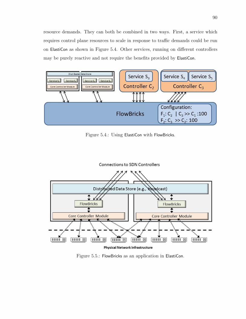
90
resource demands. They can both be combined in two ways. First, a service which
requires control plane resources to scale in response to tra�c demands could be run
on ElastiCon as shown in Figure 5.4. Other services, running on di↵erent controllers
may be purely reactive and not require the benefits provided by ElastiCon.
Figure 5.4.: Using ElastiCon with FlowBricks.
Figure 5.5.: FlowBricks as an application in ElastiCon.

91
Also, ElastiCon may be used to improve the scalability of FlowBricks itself Figure 5.5.
The application in ElastiCon would be implement the service composition algorithm
described in Section 5.2. It would also be responsible for maintaining TCP con-
nections with the controllers while the core module would maintain the switch TCP
connections. ElastiCon would allow dynamic addition and removal of flowbricks servers
in response to control plane resource demands. When a server is added to FlowBricks,
the core controller module would dynamically migrate switches to the new server.
The application would be responsible for migrating TCP connections to the hetero-
geneous controllers and reading and writing state (like flow table number map) to the
distributed key-value store.
5.5 Evaluation
In this section, we describe our implementation and use it to evaluate the overhead
imposed by FlowBricks.
5.5.1 Implementation
We considered implementing FlowBricks as a plugin for Pyretic. However, Pyretic’s
core module computes a cross product to combine flow tables. During cross product
of flow tables, flow table entry features (like timeouts) are lost. This prevented us
from using Pyretic to implement FlowBricks.
FlowBricks can be implemented as a module in any controller (we chose Flood-
light [46]). We reused Floodlight’s core module for communication with switches.
The switches in the network are configured with the IP address and TCP port of
Floodlight. They establish a connection with Floodlight’s core module. The core
module sends a notification to the FlowBricks module when a new switch connects to
Floodlight.
The FlowBricks module is configured with a policy and the IP addresses and TCP
ports of the heterogeneous controllers. The module implements the switch-side com-

92
munication of the OpenFlow protocol. When it receives a notification for a new switch
from the core module, it establishes a new TCP connection with each controller. The
controllers send switch configuration messages over this connection. FlowBricks mod-
ule modifies these messages as described in previous sections and forwards them to
the switch.
For our experiments, we used Open vSwitch (OVS), an open source OpenFlow-
compliant software switch. We modified OVS to address the limitation of the Open-
Flow protocol described in Section 5.3. In particular, we allowed pipeline process-
ing to transition from a higher to lower flow table number and added support for
Execute-Actions instruction and Drop packet action.
5.5.2 Examples
To demostrate the utility and flexibility of FlowBricks, we experimented with var-
ious combinations of services and controller implementation. Table 5.1 shows the
services that we used and Table 5.2 shows the policies for combining them. We
briefly describe them below.
Table 5.1.: Services in FlowBricks
Service Abbrev. Controllers Actions
Learning Switch LS Floodlight, Packet forwardingPox, Beacon
Shortest Path Routing SPR Floodlight, Topology discovery,Pox, Beacon packet forwarding
Quality of Service QOS Floodlight Set IP DSCP bitsAccess Control AC Floodlight Packet filtering
Address Rewriting NAT Pyretic Set IP addressesDeep Packet Inspection DPI Pyretic Send packet to controller
ARP Responder ARPR Pox Send ARP response
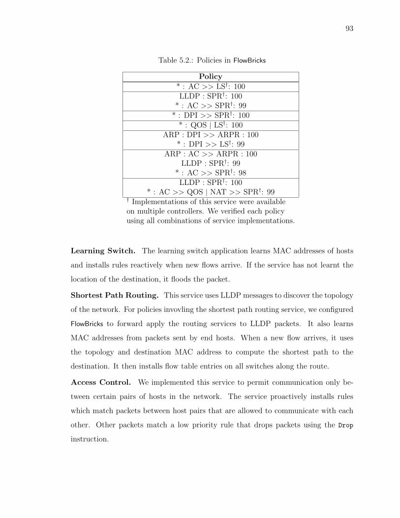
93
Table 5.2.: Policies in FlowBricks
Policy
* : AC >> LS†: 100LLDP : SPR†: 100
* : AC >> SPR†: 99* : DPI >> SPR†: 100
* : QOS | LS†: 100ARP : DPI >> ARPR : 100
* : DPI >> LS†: 99ARP : AC >> ARPR : 100
LLDP : SPR†: 99* : AC >> SPR†: 98LLDP : SPR†: 100
* : AC >> QOS | NAT >> SPR†: 99† Implementations of this service were availableon multiple controllers. We verified each policyusing all combinations of service implementations.
Learning Switch. The learning switch application learns MAC addresses of hosts
and installs rules reactively when new flows arrive. If the service has not learnt the
location of the destination, it floods the packet.
Shortest Path Routing. This service uses LLDP messages to discover the topology
of the network. For policies invovling the shortest path routing service, we configured
FlowBricks to forward apply the routing services to LLDP packets. It also learns
MAC addresses from packets sent by end hosts. When a new flow arrives, it uses
the topology and destination MAC address to compute the shortest path to the
destination. It then installs flow table entries on all switches along the route.
Access Control. We implemented this service to permit communication only be-
tween certain pairs of hosts in the network. The service proactively installs rules
which match packets between host pairs that are allowed to communicate with each
other. Other packets match a low priority rule that drops packets using the Drop
instruction.
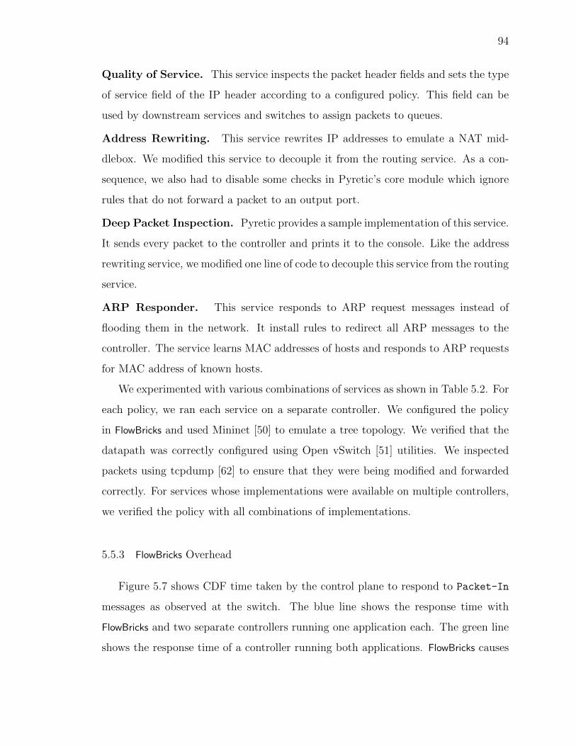
94
Quality of Service. This service inspects the packet header fields and sets the type
of service field of the IP header according to a configured policy. This field can be
used by downstream services and switches to assign packets to queues.
Address Rewriting. This service rewrites IP addresses to emulate a NAT mid-
dlebox. We modified this service to decouple it from the routing service. As a con-
sequence, we also had to disable some checks in Pyretic’s core module which ignore
rules that do not forward a packet to an output port.
Deep Packet Inspection. Pyretic provides a sample implementation of this service.
It sends every packet to the controller and prints it to the console. Like the address
rewriting service, we modified one line of code to decouple this service from the routing
service.
ARP Responder. This service responds to ARP request messages instead of
flooding them in the network. It install rules to redirect all ARP messages to the
controller. The service learns MAC addresses of hosts and responds to ARP requests
for MAC address of known hosts.
We experimented with various combinations of services as shown in Table 5.2. For
each policy, we ran each service on a separate controller. We configured the policy
in FlowBricks and used Mininet [50] to emulate a tree topology. We verified that the
datapath was correctly configured using Open vSwitch [51] utilities. We inspected
packets using tcpdump [62] to ensure that they were being modified and forwarded
correctly. For services whose implementations were available on multiple controllers,
we verified the policy with all combinations of implementations.
5.5.3 FlowBricks Overhead
Figure 5.7 shows CDF time taken by the control plane to respond to Packet-In
messages as observed at the switch. The blue line shows the response time with
FlowBricks and two separate controllers running one application each. The green line
shows the response time of a controller running both applications. FlowBricks causes

95
Server
Controller
Learning Switch
FlowBricks
Server
Cbench
Server
Cbench
(a) Co-locating with controller.
Server
Cbench
Server
Cbench
Server
Controller
Learning Switch
Server Server
FlowBricks FlowBricks
(b) Dedicated servers.
Server
Controller
Learning Switch
Server
Cbench
Server
Cbench
FlowBricks FlowBricks
(c) Co-locating with switches.
Figure 5.6.: Setup used for comparing the deployment alternatives.
a two-fold increase in response time. Inserting FlowBricks doubles the communication
overhead (transmission and message parsing time) for every message. So, the increase
in control plane response time is explained almost entirely by the fact that all control
plane tra�c needs to be redirected through FlowBricks. However, the 95th percentile
response time of 2.2ms with FlowBricks is still well below the acceptable flow setup
time of 5-10ms for LAN environments [63].
5.5.4 Performance Comparison
Since the increase in response time is almost entirely due to the additional hop in-
troduced by FlowBricks in the control plane, we expect the three deployment scenarios
(Section 5.4) to have di↵erent performance characteristics. We empirically quantify
them in this section.
Setup. For performance comparision of the three deployment alternatives described
in Section 5.4.2, we used a setup consisting of a Floodlight controller running the
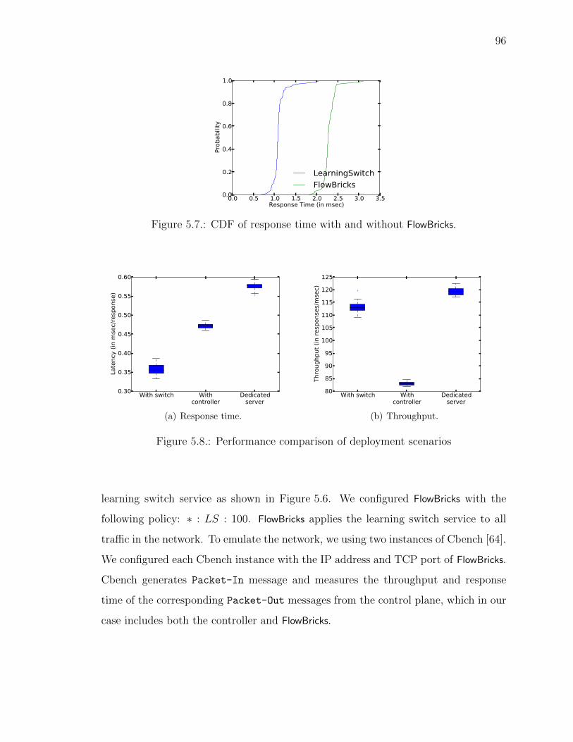
96
Figure 5.7.: CDF of response time with and without FlowBricks.
(a) Response time. (b) Throughput.
Figure 5.8.: Performance comparison of deployment scenarios
learning switch service as shown in Figure 5.6. We configured FlowBricks with the
following policy: ⇤ : LS : 100. FlowBricks applies the learning switch service to all
tra�c in the network. To emulate the network, we using two instances of Cbench [64].
We configured each Cbench instance with the IP address and TCP port of FlowBricks.
Cbench generates Packet-In message and measures the throughput and response
time of the corresponding Packet-Out messages from the control plane, which in our
case includes both the controller and FlowBricks.

97
Response Time. To measure the response time, Cbench sends one Packet-In
messages per switch and waits for a response from the controller. When it receives
a response, it measures the response time and it sends another Packet-In message.
This continues for the duration of the experiment. Figure 5.8(a) shows the response
time of the control plane as measured by Cbench. As seen in the figure, deploying
FlowBricks and controller on separate servers has the highest response time since each
control plane message traverses the network two times. Colocating FlowBricks with the
controller reduces the response time. Colocating FlowBricks with the switch, further
reduces the response time, since we now have two instances of FlowBricks instead of
one.
Throughput. Cbench measures the throughput of the control plane by ensuring
that the controller is always processing Packet-In messages for the duration of the
experiment. The ratio of the messages processed to the duration of the experiment
gives the throughput of the controller. Figure 5.8(b) shows the throughput observed
in the three scenarios. As expected, running FlowBricks and the controller on sepa-
rate servers gives the highest throughput. When FlowBricks was colocated with the
switches, it reduced the throughput by approximately 10%. This is probably because
the Cbench process consumed CPU cycles and thus reduced FlowBricks’s through-
put. The lowest throughput was observed when FlowBricks was colocated with the
controller.
Summary. The above results show that colocating FlowBricks with the switch soft-
ware leads to the lowest response time. Also, the throughput is comparable to that
achieved by running FlowBricks on a dedicated server. For software-switches like Open
vSwitch, running an instance of FlowBricks with every instance of the software switch
on end hosts is possible. However, it may not be feasible to run FlowBricks on a physical
switch unless the switch vendor allows it. So, for physical switches, choosing between
a dedicated server for FlowBricks and colocating FlowBricks with the controller involves
a trade-o↵ between response time and throughput. For deployments that expect a lot
of control plane tra�c, the server running the controllers is likely to become a bottle-
98
neck. In a such a scenario, deploying controllers and FlowBricks on separate dedicated
servers is preferred. However, for deployments where response time to network events
is more critical, it may be better to colocate FlowBricks with the controller.
5.6 Related Work
The first SDN controller was single threaded [42]. Since then, more advanced
multi-threaded controllers [45, 46] have been developed. More recently, physically
distributed SDN controllers [8,9] have been proposed to handle large networks which
are beyond the capability of a single server. This allows the operator to add and
remove features at runtime. However, all the above implementations are monolithic
controllers which focus on improving performance.
Some earlier work has focused on making controllers more flexible. Beacon [44] al-
lows dynamic addition and removal of controller modules. This allows the operator to
add and remove features at runtime. However, all modules need to be written in Java
and use Beacon’s API. Yanc [65] is a platform which exposes network configuration
and state using the file system. Controller applications are separate processes. This
allows applications to be written in any language but still requires application ven-
dors to use Yanc’s file system layout. HotSwap [66] provides a mechanism to upgrade
from one controller version to the next or move between controller vendors. It does
so by replaying network events to bring the new and old controllers to a consistent
state. However, at a given time, services from just one controller can be applied to
the tra�c in the network.
Frenetic [53] and Pyretic [28] provide a query language for describing high-level
packet-forwarding policies for parallel and serial cases of service integration. Fre-
netic and Pyretic programs easily integrate services but cannot be generalized across
controllers from several vendors.
Our system architecture resembles FlowVisor [54] at a high level. FlowVisor allows
a network operator to slice the global flow space and assign a controller to each slice.

99
FlowVisor needs to match a packet only against the flow tables of the controller of its
slice. Since FlowBricks deploys services from multiple controllers on the same flows,
a given packet needs to be matched against the flow tables of all controllers. This
introduces the problem of combining all controllers’ flow tables in the datapath, and
changes how FlowBricks processes messages which is the focus of this paper.
An SDN hypervisor [55] has been proposed to address the same problem as Flow-
Bricks. It combines policies by calculating the cross product of rules of each policy.
As the authors themselves point out, this mechanism does not handle flow table entry
timeouts. Calculating the cross product leads to an exponential increase in TCAM
space requirement for the combined policy. This could make it infeasible to deploy the
combined policy on switches with limited TCAM space. Also, the SDN hypervisor
does not support multiple flow tables since it addresses OpenFlow 1.0 which has a
single flow table.
5.7 Summary
The SDN paradigm increases the potential for flexible network systems design and
implementation. We address the problem of composing services implemented on con-
trollers from di↵erent vendors. We introduced a framework to integrate heterogeneous
controllers using only the standardized controller to switch communication protocol.
To demonstrate the feasibility of this framework, we presented its design using a
simple technique to combine flow tables from di↵erent OpenFlow-based controllers
without modifying the controllers themselves.
100
6 CONCLUSIONS
In this thesis, we explored techniques to improve the data and control plane perfor-
mance of data center networks. In particular, we focused on networks that are orga-
nized in multi-rooted tree topologies and employ the SDN paradigm. We proposed
techniques that are compatible with existing network protocols and can be readily
deployed in data centers. We empirically verified that our techniques improve the
network performance metrics like throughput and latency and consequently impact
application performance too.
We showed how a simple packet-level tra�c splitting scheme called RPS not only
leads to significantly better load balance and network utilization, but also incurs little
packet reordering since it exploits the symmetry in these networks. Furthermore, such
schemes have lower complexity and readily implementable, making them an appealing
alternative for data center networks. Real data centers also need to deal with failures
which may disturb the symmetry, impacting the performance of RPS. We observed
that by keeping queue lengths small, this impact can be minimized. We exploited
this observation by proposing a simple queue management scheme called SRED that
can cope well with failures.
To improve scalability along the control plane, we presented our design of ElastiCon,
a distributed elastic SDN controller. We designed and implemented algorithms for
switch migration, controller load balancing and elasticity which form the core of the
controller. We enhanced Mininet and used it to demonstrate the e�cacy of those
algorithms.
Finally, we proposed FlowBricks, a framework that allows integration of services
running on heterogeneous controllers in a way that is transparent to controllers and
does not require any additional standardization beyond a southbound API.

101
6.1 Future Directions
In this dissertation, we propose and empirically demonstrate that techniques that
improve the scalability of data center networks. However, we do not address fault tol-
erance while proposing these techniques. Also, the ability to easily integrate services
independently of existing services in an SDN controller presents the opportunity to
develop new services.
6.1.1 Fault Tolerance
Our current design of FlowBricks and ElastiCon does not address issues caused
by failures, although we believe fault tolerance mechanisms can easily fit into these
architectures. For ElastiCon, this may require running three or more controllers in
equal role for each switch and using a consensus protocol between them to ensure
there is always at least one master even if the new master crashes. In FlowBricks, we
want to explore algorithms for making FlowBricks stateless. If FlowBricks is stateless, a
new instance of FlowBricks can be triggered when an instance crashes. However, this
would involve changing the southbound API to include some state-information with
every action in a flow table entry.
6.1.2 New SDN Services
Going forward we plan to develop controllers with management and monitoring
services that can be plugged into FlowBricks at runtime to monitor performance and
debug the network. For example, new services can be added to the beginning and end
of the policies in FlowBricks. The service in the beginning of the policy would insert
new packets in the network using the Packet-Out messages and the service at the end
could verify that the packet was correctly modified by intermediate services. We also
plan to integrate existing techniques [27, 59] into FlowBricks to guarantee consistency
and correctness of composed services.

REFERENCES
102
REFERENCES
[1] Albert Greenberg, James R. Hamilton, Navendu Jain, Srikanth Kandula,Changhoon Kim, Parantap Lahiri, David A. Maltz, Parveen Patel, and SudiptaSengupta. VL2: A Scalable and Flexible Data Center Network. In Proceedingsof the ACM SIGCOMM 2009 Conference on Data Communication, SIGCOMM’09, pages 51–62, New York, NY, USA, 2009. ACM.
[2] Mohammad Al-Fares, Alexander Loukissas, and Amin Vahdat. A Scalable, Com-modity Data Center Network Architecture. In Proceedings of the ACM SIG-COMM 2008 Conference on Data Communication, SIGCOMM ’08, pages 63–74,New York, NY, USA, 2008. ACM.
[3] Srikanth Kandula, Sudipta Sengupta, Albert Greenberg, Parveen Patel, andRonnie Chaiken. The Nature of Data Center Tra�c: Measurements & Analysis.In Proceedings of the 9th ACM SIGCOMM Conference on Internet MeasurementConference, IMC ’09, pages 202–208, New York, NY, USA, 2009. ACM.
[4] Theophilus Benson, Ashok Anand, Aditya Akella, and Ming Zhang. Understand-ing Data Center Tra�c Characteristics. In Proceedings of the 1st ACM Workshopon Research on Enterprise Networking, WREN ’09, pages 65–72, New York, NY,USA, 2009. ACM.
[5] Mohammad Al-Fares, Sivasankar Radhakrishnan, Barath Raghavan, NelsonHuang, and Amin Vahdat. Hedera: Dynamic Flow Scheduling for Data CenterNetworks. In Proceedings of the 7th USENIX Symposium on Networked SystemsDesign and Implementation, NSDI ’10, pages 281–296, Berkeley, CA, USA, 2010.USENIX Association.
[6] Andrew R. Curtis, Wonho Kim, and Praveen Yalagandula. Mahout: Low-Overhead Datacenter Tra�c Management using End-Host-Based Elephant De-tection. In Proceedings of the 30th IEEE International Conference on ComputerCommunications, INFOCOM ’11, pages 1629–1637. IEEE, 2011.
[7] Costin Raiciu, Sebastien Barre, Christopher Pluntke, Adam Greenhalgh, DamonWischik, and Mark Handley. Improving Datacenter Performance and Robustnesswith Multipath TCP. In Proceedings of the ACM SIGCOMM 2012 Conferenceon Data Communication, SIGCOMM ’11, pages 266–277, New York, NY, USA,2011. ACM.
[8] Teemu Koponen, Martin Casado, Natasha Gude, Jeremy Stribling, LeonPoutievski, Min Zhu, Rajiv Ramanathan, Yuichiro Iwata, Hiroaki Inoue,Takayuki Hama, and Scott Shenker. Onix: A Distributed Control Platform forLarge-scale Production Networks. In Proceedings of the 9th USENIX Symposiumon Operating Systems Design and Implementation, OSDI ’10, pages 351–364,Berkeley, CA, USA, 2010. USENIX Association.

103
[9] Amin Tootoonchian and Yashar Ganjali. HyperFlow: A Distributed ControlPlane for OpenFlow. In Proceedings of the 2010 Internet Network ManagementConference on Research on Enterprise Networking, INM/WREN ’10, pages 3–3,Berkeley, CA, USA, 2010. USENIX Association.
[10] Dan Levin, Andreas Wundsam, Brandon Heller, Nikhil Handigol, and Anja Feld-mann. Logically Centralized?: State Distribution Trade-o↵s in Software DefinedNetworks. In Proceedings of the 1st ACM SIGCOMM Workshop on Hot Topicsin Software Defined Networks, HotSDN ’12, pages 1–6, New York, NY, USA,2012. ACM.
[11] Theophilus Benson, Aditya Akella, and David A. Maltz. Network Tra�c Charac-teristics of Data Centers in the Wild. In Proceedings of the 10th ACM SIGCOMMConference on Internet Measurement, IMC ’10, pages 267–280, New York, NY,USA, 2010. ACM.
[12] Sushant Jain, Alok Kumar, Subhasree Mandal, Joon Ong, Leon Poutievski, Ar-jun Singh, Subbaiah Venkata, Jim Wanderer, Junlan Zhou, Min Zhu, Jon Zolla,Urs Holzle, Stephen Stuart, and Amin Vahdat. B4: Experience with a Globally-deployed Software Defined Wan. In Proceedings of the ACM SIGCOMM 2013Conference on Data Communication, SIGCOMM ’13, pages 3–14, New York,NY, USA, 2013. ACM.
[13] Sally Floyd and Van Jacobson. Random Early Detection Gateways for Conges-tion Avoidance. IEEE/ACM Transactions on Networking, 1(4):397–413, August1993.
[14] Doug Beaver, Sanjeev Kumar, Harry C. Li, Jason Sobel, and Peter Vajgel.Finding a Needle in Haystack: Facebook’s Photo Storage. In Proceedings ofthe 9th USENIX Conference on Operating Systems Design and Implementation,OSDI’10, pages 1–8, Berkeley, CA, USA, 2010. USENIX Association.
[15] Ajay Gulati, Anne Holler, Minwen Ji, Ganesha Shanmuganathan, Carl Wald-spurger, and Xiaoyun Zhu. VMware Distributed Resource Management: Design,Implementation and Lessons Learned. Technical report, VMWare, Inc, Palo Alto,California, 2012.
[16] Rishi Kapoor, George Porter, Malveeka Tewari, Geo↵rey M. Voelker, and AminVahdat. Chronos: Predictable Low Latency for Data Center Applications. InProceedings of the 3rd ACM Symposium on Cloud Computing, SoCC ’12, pages9:1–9:14, New York, NY, USA, 2012. ACM.
[17] George Porter, Richard Strong, Nathan Farrington, Alex Forencich, Pang Chen-Sun, Tajana Rosing, Yeshaiahu Fainman, George Papen, and Amin Vahdat.Integrating Microsecond Circuit Switching into the Data Center. In Proceedingsof the ACM SIGCOMM 2013 Conference on Data Communication, SIGCOMM’13, pages 447–458, New York, NY, USA, 2013. ACM.
[18] Chuanxiong Guo, Guohan Lu, Dan Li, Haitao Wu, Xuan Zhang, Yunfeng Shi,Chen Tian, Yongguang Zhang, and Songwu Lu. BCube: A High Performance,Server-centric Network Architecture for Modular Data Centers. In Proceedingsof the ACM SIGCOMM 2009 Conference on Data Communication, SIGCOMM’09, pages 63–74, New York, NY, USA, 2009. ACM.
104
[19] Je↵rey Dean and Sanjay Ghemawat. MapReduce: Simplified Data Processingon Large Clusters. Communications of the ACM, 51(1):107–113, January 2008.
[20] Haitao Wu, Zhenqian Feng, Chuanxiong Guo, and Yongguang Zhang. ICTCP:Incast Congestion Control for TCP in Data Center Networks. In Proceedingsof the 6th International Conference on Emerging Networking Experiments andTechnologies, Co-NEXT ’10, pages 13:1–13:12, New York, NY, USA, 2010. ACM.
[21] Mohammad Alizadeh, Albert Greenberg, David A. Maltz, Jitendra Padhye,Parveen Patel, Balaji Prabhakar, Sudipta Sengupta, and Murari Sridharan. DataCenter TCP (DCTCP). In Proceedings of the ACM SIGCOMM 2010 Confer-ence on Data Communication, SIGCOMM ’10, pages 63–74, New York, NY,USA, 2010. ACM.
[22] Balajee Vamanan, Jahangir Hasan, and T.N. Vijaykumar. Deadline-aware Dat-acenter TCP (D2TCP). In Proceedings of the ACM SIGCOMM 2012 Conferenceon Data Communication, SIGCOMM ’12, pages 115–126, New York, NY, USA,2012. ACM.
[23] Nick McKeown, Tom Anderson, Hari Balakrishnan, Guru Parulkar, et al. Open-Flow: Enabling Innovation in Campus Networks. SIGCOMM Computer Com-munication Review, 38(2), March 2008.
[24] Minlan Yu, Lavanya Jose, and Rui Miao. Software Defined Tra�c Measurementwith OpenSketch. In Proceedings of the 10th USENIX Symposium on NetworkedSystems Design and Implementation, NSDI ’13, pages 29–42, Berkeley, CA, USA,2013. USENIX Association.
[25] Vimalkumar Jeyakumar, Mohammad Alizadeh, Yilong Geng, Changhoon Kim,and David Mazires. Millions of Little Minions: Using Packets for Low LatencyNetwork Programming and Visibility. In Proceedings of the ACM SIGCOMM2014 Conference on Data Communication, SIGCOMM ’14, pages 3–14, NewYork, NY, USA, 2014. ACM.
[26] Nikhil Handigol, Brandon Heller, Vimalkumar Jeyakumar, David Mazieres, andNick McKeown. I Know What Your Packet Did Last Hop: Using Packet Historiesto Troubleshoot Networks. In Proceedings of the 11th USENIX Symposium onNetworked Systems Design and Implementation, NSDI ’14, pages 71–85, Berke-ley, CA, USA, 2014. USENIX Association.
[27] Ahmed Khurshid, Xuan Zou, Wenxuan Zhou, Matthew Caesar, and P. BrightenGodfrey. VeriFlow: Verifying Network-wide Invariants in Real Time. In Pro-ceedings of the 10th USENIX Conference on Networked Systems Design andImplementation, NSDI ’13, pages 15–28, Berkeley, CA, USA, 2013. USENIXAssociation.
[28] Christopher Monsanto, Joshua Reicha, Nate Foster, Jennifer Rexford, and DavidWalker. Composing Software-Defined Networks. In Proceedings of the 10thUSENIX Symposium on Networked Systems Design and Implementation, NSDI’13, pages 1–13, Berkeley, CA, USA, 2013. USENIX Association.
[29] Zafar Ayyub Qazi, Cheng-Chun Tu, Luis Chiang, Rui Miao, Vyas Sekar, andMinlan Yu. SIMPLE-fying Middlebox Policy Enforcement Using SDN. In Pro-ceedings of the ACM SIGCOMM 2013 Conference on Data Communication, SIG-COMM ’13, pages 27–38, New York, NY, USA, 2013. ACM.

105
[30] Per packet load balancing. http://www.cisco.com/en/US/docs/ios/12 0s/feature/guide/pplb.html. Accessed July 2012.
[31] M. Laor and L. Gendel. The E↵ect of Packet Reordering in a Backbone Link onApplication Throughput. Network, IEEE, 16(5):28–36, sep 2002.
[32] Mohammad Alizadeh, Abdul Kabbani, Tom Edsall, Balaji Prabhakar, AminVahdat, and Masato Yasuda. Less Is More: Trading a Little Bandwidth for Ultra-Low Latency in the Data Center. In Proceedings of the 9th USENIX Symposiumon Networked Systems Design and Implementation, NSDI ’12, pages 253–266,Berkeley, CA, USA, 2012. USENIX Association.
[33] Ethan Blanton and Mark Allman. Using TCP DSACKs and SCTP DuplicateTransmission Sequence Numbers (TSNs) to Detect Spurious Retransmissions.Request for Comments (Experimental) 3708, Internet Engineering Task Force,February 2004.
[34] Sumitha Bhandarkar, A. L. Narasimha Reddy, Mark Allman, and Ethan Blan-ton. Improving the Robustness of TCP to Non-Congestion Events. Request forComments (Experimental) 4653, Internet Engineering Task Force, August 2006.
[35] David Zats, Tathagata Das, Prashanth Mohan, Dhruba Borthakur, and RandyKatz. DeTail: Reducing the Flow Completion Time Tail in Datacenter Networks.In Proceedings of the ACM SIGCOMM 2012 Conference on Data Communica-tion, SIGCOMM ’12, pages 139–150, New York, NY, USA, 2012. ACM.
[36] Sebastien Barr. MultiPath TCP in the Linux Kernel. https://scm.info.ucl.ac.be/trac/mptcp/wiki/install. Accessed July 2012.
[37] K. K. Ramakrishnan, Sally Floyd, and David Black. The Addition of ExplicitCongestion Notification (ECN) to IP. Request for Comments (Proposed Stan-dard) 3168, Internet Engineering Task Force, September 2001.
[38] Albert Greenberg, Parantap Lahiri, David A. Maltz, Parveen Patel, and SudiptaSengupta. Towards a Next Generation Data Center Architecture: Scalabilityand Commoditization. In Proceedings of the ACM Workshop on ProgrammableRouters for Extensible Services of Tomorrow, PRESTO ’08, pages 57–62, NewYork, NY, USA, 2008. ACM.
[39] Shan Sinha, Srikanth Kandula, and Dina Katabi. Harnessing TCPs Burstinessusing Flowlet Switching. In Proceedings of the 3rd ACM Workshop on Hot Topicsin Networks, HotNets-III, New York, NY, USA, 2004. ACM.
[40] Ping Pan and Thomas Nadeau. Software-Defined Network (SDN) Problem State-ment and Use Cases for Data Center Applications. Internet-Draft (StandardsTrack), Internet Engineering Task Force, March 2012.
[41] Andrew R. Curtis, Je↵rey C. Mogul, Jean Tourrilhes, Praveen Yalagandula,Puneet Sharma, and Sujata Banerjee. DevoFlow: Scaling Flow Managementfor High-performance Networks. In Proceedings of the ACM SIGCOMM 2011Conference on Data Communication, SIGCOMM ’11, pages 254–265, New York,NY, USA, 2011. ACM.

106
[42] Natasha Gude, Teemu Koponen, Justin Pettit, Ben Pfa↵, Martın Casado, NickMcKeown, and Scott Shenker. NOX: Towards an Operating System for Networks.SIGCOMM Computer Commununication Review, 38(3):105–110, 2008.
[43] Amin Tootoonchian, Sergey Gorbunov, Yashar Ganjali, Martin Casado, andRob Sherwood. On Controller Performance in Software-Defined Networks. InProceedings of the 2nd USENIX Workshop on Hot Topics in Management ofInternet, Cloud, and Enterprise Networks and Services, HotICE ’12, Berkeley,CA, 2012. USENIX Association.
[44] David Erickson. The Beacon OpenFlow Controller. In Proceedings of the2nd ACM SIGCOMM Workshop on Hot Topics in Software Defined Networks,HotSDN ’13, pages 13–18, New York, NY, USA, 2013. ACM.
[45] Z. Cai, A. L. Cox, and T. S. E. Ng. Maestro: A System for Scalable Open-Flow Control. Technical report, Computer Science Department, Rice University,Houston, Texas, 2010.
[46] Floodlight. http://www.projectfloodlight.org/floodlight/. Accessed March2013.
[47] OpenDaylight. http://www.opendaylight.org/. Accessed May 2014.
[48] Open Networking Foundation. OpenFlow Management and Configuration Pro-tocol (OF-Config 1.1), June 2012.
[49] Hyperic SIGAR API. http://www.hyperic.com/products/sigar. Accessed May2014.
[50] Nikhil Handigol, Brandon Heller, Vimalkumar Jeyakumar, Bob Lantz, and NickMcKeown. Reproducible Network Experiments Using Container-based Emula-tion. In Proceedings of the 8th International Conference on Emerging Network-ing Experiments and Technologies, CoNEXT ’12, pages 253–264, New York, NY,USA, 2012. ACM.
[51] Ben Pfa↵, Justin Pettit, Keith Amidon, Martin Casado, Teemu Koponen, andScott Shenker. Extending Networking into the Virtualization Layer. In Proceed-ings of the 8th ACM Workshop on Hot Topics in Networks, HotNets-VIII, pages1–6, New York, NY, USA, 2009. ACM.
[52] Barath Raghavan, Martın Casado, Teemu Koponen, Sylvia Ratnasamy, Ali Gh-odsi, and Scott Shenker. Software-defined Internet Architecture: DecouplingArchitecture from Infrastructure. In Proceedings of the 11th ACM Workshop onHot Topics in Networks, HotNets-XI, pages 43–48, New York, NY, USA, 2012.ACM.
[53] Nate Foster, Rob Harrison, Michael J. Freedman, Christopher Monsanto, Jen-nifer Rexford, Alec Story, and David Walker. Frenetic: A Network ProgrammingLanguage. In Proceedings of the 16th ACM SIGPLAN International Conferenceon Functional Programming, ICFP ’11, pages 279–291, New York, NY, USA,2011. ACM.

107
[54] Rob Sherwood, Glen Gibb, Kok-Kiong Yap, Guido Appenzeller, Martin Casado,Nick McKeown, and Guru M. Parulkar. Can the Production Network Be theTestbed? In Proceedings of the 9th USENIX Symposium on Operating SystemsDesign and Implementation, OSDI ’10, pages 365–378, Berkeley, CA, USA, 2010.USENIX Association.
[55] X. Jin, J. Rexford, and D. Walker. Incremental Update for a CompositionalSDN Hypervisor. In Proceedings of the 3rd ACM SIGCOMM Workshop on HotTopics in Software Defined Networks, HotSDN ’14, pages 187–192, New York,NY, USA, 2014. ACM.
[56] Open Networking Foundation. OpenFlow Switch Specification (Version 1.1.0),February 2011.
[57] Carolyn Jane Anderson, Nate Foster, Arjun Guha, Jean-Baptiste Jeannin, Dex-ter Kozen, Cole Schlesinger, and David Walker. NetKAT: Semantic Foundationsfor Networks. In Proceedings of the 41st ACM SIGPLAN-SIGACT Symposiumon Principles of Programming Languages, POPL ’14, pages 113–126, New York,NY, USA, 2014. ACM.
[58] Open Networking Foundation. OpenFlow Switch Specification (Version 1.4.0),October 2013.
[59] Mark Reitblatt, Nate Foster, Jennifer Rexford, Cole Schlesinger, and DavidWalker. Abstractions for Network Update. In Proceedings of the ACM SIG-COMM 2012 Conference on Data Communication, SIGCOMM ’12, pages 323–334, New York, NY, USA, 2012. ACM.
[60] Alexander Kesselman, Kirill Kogan, Sergey Nemzer, and Michael Segal. Spaceand Speed Tradeo↵s in TCAM Hierarchical Packet Classification. Journal ofComputer System Sciences, 79(1):111–121, February 2013.
[61] Kirill Kogan, Sergey Nikolenko, Ori Rottenstreich, William Culhane, and PatrickEugster. SAX-PAC (Scalable And eXpressive PAcket Classification). In Proceed-ings of the 2014 ACM Conference on SIGCOMM, SIGCOMM ’14, pages 15–26,New York, NY, USA, 2014. ACM.
[62] Henry Van Styn. Tcpdump Fu. Linux Journal, 2011(210):90–97, October 2011.
[63] M. Kobayashi, S. Seetharamn, G. Parulkar, G. Appenzeller, J. Little, J. van Rei-jendam, P. Weissmann, and N. McKeown. Maturing of OpenFlow and Software-Defined Networking through Deployments. Computer Networks, 61(0):151–175,March 2014.
[64] Cbench. http://www.openflowhub.org/display/floodlightcontroller/Cbench+(New). Accessed September 2014.
[65] Matthew Monaco, Oliver Michel, and Eric Keller. Applying Operating SystemPrinciples to SDN Controller Design. In Proceedings of the 12th ACM Workshopon Hot Topics in Networks, HotNets-XII, pages 2:1–2:7, New York, NY, USA,2013. ACM.

108
[66] Laurent Vanbever, Joshua Reich, Theophilus Benson, Nate Foster, and JenniferRexford. HotSwap: Correct and E�cient Controller Upgrades for Software-Defined Networks. In Proceedings of the 2nd ACM SIGCOMM Workshop onHot Topics in Software Defined Networking, HotSDN ’13, pages 133–138, NewYork, NY, USA, 2013. ACM.

VITA

109
VITA
Advait Abhay Dixit received his B.Tech in computer science and engineering from
Indian Institute of Technology, Guwahati, India in 2003. He received his M.S. in
computer science from the University of California, Los Angeles in 2004 where his
research focused on sensor networks. He started his graduate studies in the Computer
Science Department at Purdue University in 2010, where he worked on various aspects
of data center networking. During the course of his graduate studies, he interned at
Google Inc, NEC Labs America and Bell Labs. He spent one year as a research
assistant in the Rosen Center for Advanced Computing working on grid computing
applications while pursuing his Ph.D.