technical writing samples
TRANSCRIPT

Technical Communication
Samples

Procedures
Elevation 95X-ALLXX-01 Commercial Cross-trainer
“How To…”
41
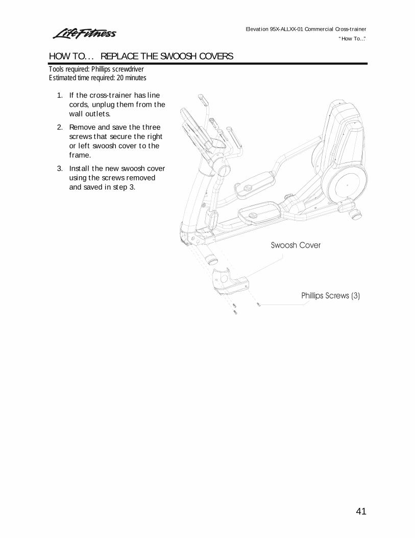
Swoosh Cover
Phillips Screws (3)
HOW TO... REPLACE THE SWOOSH COVERS Tools required: Phillips screwdriver Estimated time required: 20 minutes
1. If the cross-trainer has line cords, unplug them from the wall outlets.
2. Remove and save the three screws that secure the right or left swoosh cover to the frame.
3. Install the new swoosh cover using the screws removed and saved in step 3.

Elevation 95X-ALLXX-01 Commercial Cross-trainer
“How To…”
59
BoltKeyed Washer
Washer
Rocker Assembly
Inner Rocker Assembly Mounting Screws (12)
Inner RockerAssembly Cover
Inner Rocker AssemblyCover Mounting Bracket
HOW TO... REPLACE THE INNER ROCKER ASSEMBLY COVER Tools required: Phillips screwdriver, 4mm Allen wrench, 13mm and 19mm socket wrenches Estimated time required: 60 minutes
1. If the cross-trainer has line cords, unplug them from the wall outlets.
2. Remove the lower rocker assembly cover. (See the “How To…” on page 55.)
3. Remove and save the twelve screws and washers that secure the inner rocker assembly cover to the inner rocker assembly cover-mounting bracket.
4. Remove the bolt and keyed washer that secure the rocker assembly to the main shaft.
5. Carefully slide the rocker assembly off the main shaft.
6. Remove the old inner rocker assembly cover.
7. Place the new inner rocker assembly cover in position on the main shaft.
8. Carefully slide the rocker assembly onto the main shaft and position it on the shaft so that the keyed washer lines up with the slot in the shaft. Use the bolt and keyed washer removed in Step 5.
9. Line up the inner rocker assembly cover mounting holes with the holes in the inner rocker assembly cover mounting bracket and secure it with the twelve screws and washers removed in step 4.
10. Complete the installation of remaining components in reverse order.

Models 95L, 95LWEZ, and 95LE Summit Trainers How To…
102
HOW TO… REPLACE THE CONTROL LINK ASSEMBLY Tools required: Phillips screwdriver, metric Allen set, snap ring pliers Estimated repair time: 30 minutes 1. Remove the main shroud assembly (see “How To...” on page 86).
2. Remove the rocker arm cover (see “How To...” on page 92).
3. Remove the lever joint cover assembly (see “How To...” on page 93).
4. Remove the control link cap where the control link attaches to the pedal adaptor.
5. Remove the Allen bolt and washer that secure the control link assembly to the pedal adaptor.
6. Remove the snap ring that holds the rocker arm to the control link shaft.
7. Carefully remove the control link assembly from the Summit Trainer. Note the orientation of the thrust washer and hardened washer when separating the rocker arm from the control link assembly.
8. Reverse steps 1 through 6 to install the new control link assembly.
Snap Ring
Rocker Arm Cover
Thrust Washer
Control Link AssemblyLever Joint Cover
Hardened Washer
Rocker Arm
Clevis Cover
Control Link
Cap
Allen Bolt,torque to
20-30 ft-lbs(30-41 Nm)
Washer
Models 95L, 95LWEZ, and 95LE Summit Trainers How To…
89
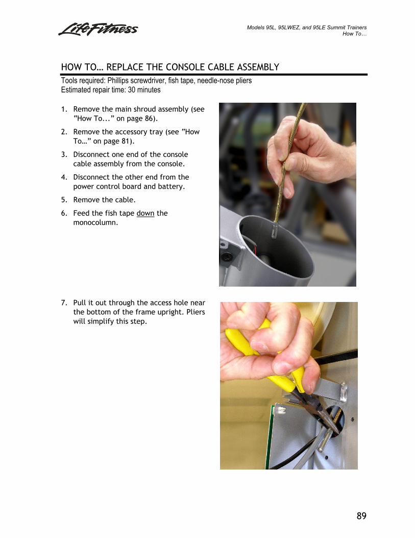
HOW TO… REPLACE THE CONSOLE CABLE ASSEMBLY Tools required: Phillips screwdriver, fish tape, needle-nose pliers Estimated repair time: 30 minutes 1. Remove the main shroud assembly (see
“How To...” on page 86).
2. Remove the accessory tray (see “How To…” on page 81).
3. Disconnect one end of the console cable assembly from the console.
4. Disconnect the other end from the power control board and battery.
5. Remove the cable.
6. Feed the fish tape down the monocolumn.
7. Pull it out through the access hole near the bottom of the frame upright. Pliers will simplify this step.

Models 95L, 95LWEZ, and 95LE Summit Trainers How To…
90
HOW TO… REPLACE THE CONSOLE CABLE ASSEMBLY - CONTINUED 8. Fasten the 16-pin console connector end of
the new cable to the fish tape with electrical tape as shown.
9. Use the fish tape to feed the console cable up through the frame and monocolumn.
10. Reverse steps 1 through 5 to complete the console cable assembly installation.

Parts Manuals
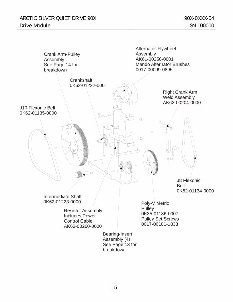
15
ARCTIC SILVER QUIET DRIVE 90X 90X-0XXX-04 Drive Module SN 100000
Poly-V MetricPulley0K35-01186-0007Pulley Set Screws0017-00101-1833
J8 FlexonicBelt0K62-01134-0000
Right Crank ArmWeld AssemblyAK62-00204-0000
Alternator-FlywheelAssemblyAK61-00250-0001Mando Alternator Brushes0017-00009-0895
Crankshaft0K62-01222-0001
Crank Arm-PulleyAssemblySee Page 14 forbreakdown
J10 Flexonic Belt0K62-01135-0000
Intermediate Shaft0K62-01223-0000
Resistor AssemblyIncludes PowerControl CableAK62-00260-0000
Bearing-InsertAssembly (4)See Page 13 forbreakdown
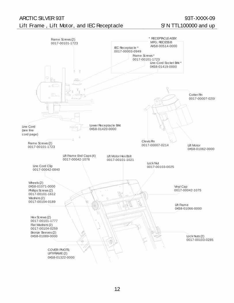
12
ARCTIC SILVER 93T 93T-XXXX-09 Lift Frame , Lift Motor, and IEC Receptacle S/N TTL100000 and up
Cotter Pin0017-00007-0208
Clevis Pin0017-00007-0214 Lift Motor
0K58-01062-0000
Lock Nuts (2)0017-00103-0285
Hex Screws (2)0017-00101-1777Flat Washers (2)0017-00104-0259Bronze Sleeves (2)0K58-01089-0000
Line Cord Clip0017-00042-0840
Lift Frame0K58-01066-0000
Lock Nut0017-00103-0025
Lift Motor Hex Bolt0017-00101-1021
Vinyl Cap0017-00042-1075
Wheels (2)0K58-01071-0000Phillips Screws (2)0017-00101-1612Washers (2)0017-00104-0189
Lift Frame End Caps (4)0017-00042-1076
Frame Screws (2)0017-00101-1723
Frame Screws *0017-00101-1723
Line-Cord Socket Brkt *0K58-01419-0000
Line Cord(see line cord page)
Lower Receptacle Brkt0K58-01420-0000
Frame Screws (2)0017-00101-1723
IEC Receptacle *0017-00003-0949
COVER: PIVOTS; LIFT-FRAME (2)0K58-01322-0000
* RECEPTACLE-ASSY: MFG; RECESS B AK58-00514-0000

14
ARCTIC SILVER 95Ri 95R-0XXX-04 Seat Assembly S/N CCU100000 and up
End Caps (4)0K19-01208-0001
Seat AssemblyAK51-00023-0003
Hex Bolts (4)0017-00101-1749
Washers (8)0017-00104-0461
Screws (4)0017-00101-1745
Bushing Hole0017-00042-0866
Screws (2)0017-00101-1282
Upper Flex Cable Clamp0K19-01221-0000
Flat-Flex CableAK19-00082-0001
Cable Sleeve0K19-01230-0000
Heart Rate Electrode AK63-00014-0003Handlebar w/InsertAK39-00024-0002
Tape (2)0K19-01222-0000
Double-sidedFoam Tape (2)0K19-01222-0000

20
ARCTIC SILVER 95Ri 95R-0XXX-04 Wheel and Leveler S/N CCU100000 and up
Pan Screws (2)0017-00101-1747
Wheel Screw0017-00101-1747
Flat Washer0K63-01041-0000
Wheel Insert0K63-01039-0000
Wheel AssemblyAK63-00016-0001
Lock Nut0017-00103-0273
Leveler0017-00009-0795
Leveler AssemblyAK61-00035-0000
Rear StabilizerGK39-00002-0012
End Cap0K63-01219-0001

Illustrations
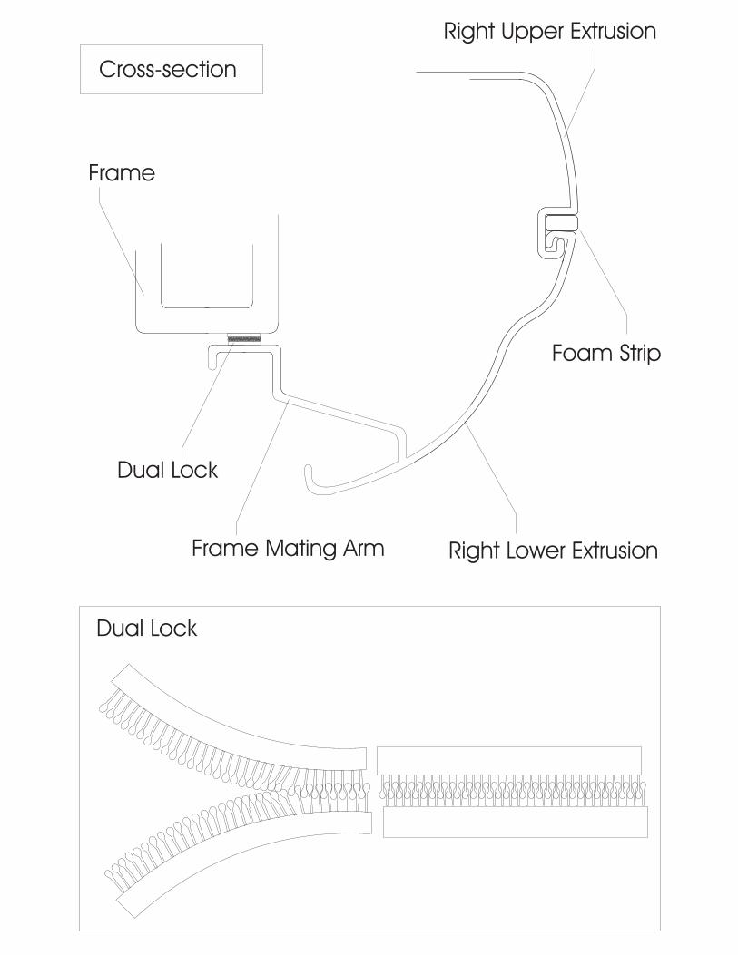
Frame
Dual Lock
Frame Mating Arm
Right Upper Extrusion
Right Lower Extrusion
Foam Strip
Cross-section
Dual Lock
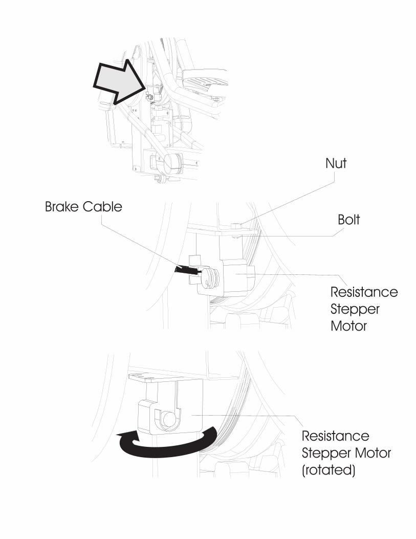
Brake Cable
Nut
Bolt
ResistanceStepperMotor
ResistanceStepper Motor(rotated)

Step 5: first and second Phillips screws visible through frame
Step 5: third screw visible
Outside Telescoping Shroud
Phillips Screws (4)
InsideTelescopingShroud
PhillipsScrews (2)

Step 6: measurethis distance
Idler Bracket Left Side Plate
J-hook
Brake Cable
Slide Block
Eddy Current
Brake
Hex Bolt
Idler BracketMounting Bolts (3)
Drive Belt
Left Side Plate(pull away justenough to allowdrive belt to beremoved)
Eddy Current Brake

Service Bulletins

Life Fitness proprietary and confidential information – For the use of the intended recipient only - Do not reproduce or distribute.
Fig. 1: new stabilizer cap
Stabilizer Cap
Fig. 2: typical stabilizer cap location
Original Date 25 Apr 2008
Revised Date n/a
Pages 1
Author Lawrence Triplett
Subject: New Stabilizer Cap Serial Number:
Distribute To: Internal Dealer ISO Installer Customer
DESCRIPTION
A new stabilizer cap, part no. 0K68-01129-0000 (shown in Figures 1 and 2), is now available∗. This cap is made of a more flexible rubber which will eliminate the problem with cracking stabilizer caps.
AFFECTED MODELS
Model
Serial No. Prefix
Quantity Needed per Unit
90X-01 XTA 90X-02 AWD. XHA 90X-03 XHA 90X-04 XWB 90XW-02 AWE 90XW-03 XHB 93X-01 XTB 93X-02 ACH, XHF 93X-03 AXA, XHF 93X-04 XWF 93X-05 XHF 93XW-02 AWF, XHG 93XW-03 AXD, XHG cross-trainers 95X-01 XTD 4 95X-02 ACJ, XHK 95X-03 AXB, XHK 95X-04 XHK 95X-05 XHK 95XE-01 XTC 95XE-02 ACK, XHM 95XE-03 AXG, XHM 95XE-04 XWE 95XE-05 XHM 95XEZ-01 WZX 95XW-02 AWG, XHL 95XW-03 AXF, XHL 95XWEZ XWM
95L-01 LXX 95LE-01 LEX Summit trainers 95LWEZ-01 LEZ
2
∗The new stabilizer cap replaces part no. 0K62-01003-0000.
Document No: CT08042502N

Life Fitness proprietary and confidential information – For the use of the intended recipient only - Do not reproduce or distribute.
Original Date: January 24, 2007 Author
Revised Date:
Problem Code
n/a
Warranty Yes No
Parts Labor
Pages 1
Richard Herr
Subject:
Serial Number:
Reference Bulletin No.:
Current Cross-trainer Control Link Assemblies
90X, 93X, and 95X (all models)
Distribute To: Internal Dealer ISO Installer Customer
DESCRIPTION Dual Sourcing of Link Balls on Tie Rod/Extension Assemblies Ending. Life Fitness has used two vendors (IKO and THK) to provide the link balls on the tie rod/extension assemblies used on our current production cross-trainers. In the future, only link balls produced by THK will be used. IKO link balls have been found to fail prematurely. If you have any assemblies with IKO link balls in your inventory, contact your RSM to have them removed and replaced with assemblies with THK link balls. These assemblies are part of the GK62-00002-0015 service kits. Existing kits must be inspected to determine which link balls they use (see illustrations).
Document No: CT07012401N
Old Style (IKO) Link Ball
Current (THK) Link Ball

Life Fitness proprietary and confidential information – For the use of the intended recipient only - Do not reproduce or distribute
Original Date
27-Jun-06
Revised Date
Problem Code
15105
Warranty Yes No Parts Labor
Pages
1
Author
John Chavez
Subject: Serial Number:
Activity Zone Ribbon Cable Is Coming Loose ALL 95T, 95TE, 97T, and 97TE – 07 with the Activity Zone assembly
Time Required: 15 min 30 min 45 min 1 hr+
Distribute To: Internal Dealer ISO Installer Customer
DESCRIPTION The ribbon cable from the Activity Zone bezel is coming loose from the Activity Zone module assembly.
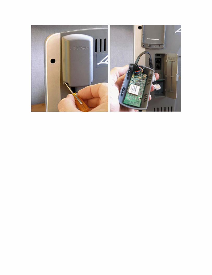
SOLUTION Reinsert the Activity Zone’s bezel ribbon cable back into P9 on the Activity Zone module assembly.
TOOLS REQUIRED Phillips screwdriver
PROCEDURE 1. Turn the treadmill power off at the on/off switch.
2. Unplug the line cord at the wall outlet.
3. Remove the two screws from the back of the Ergo Bar that secure the Activity Zone assembly (see Fig. 1).
4. Lift off the Activity Zone assembly just enough to disconnect the 4-Pin connector from the Activity Zone circuit board.
5. Reinstall the ribbon cable into the P2 connector (Fig. 2, Fig. 3).
6. Reassemble the Activity Zone module in reverse order.
Bulletin No: TR06062701N
Ergo Bar Assembly MountingScrews & Washers
Activity Zone Module AssemblyFig. 1: Ergo Bar and Activity Zone
Fig. 2: Loose ribbon cable Fig. 3: Correctly-attached ribbon cable

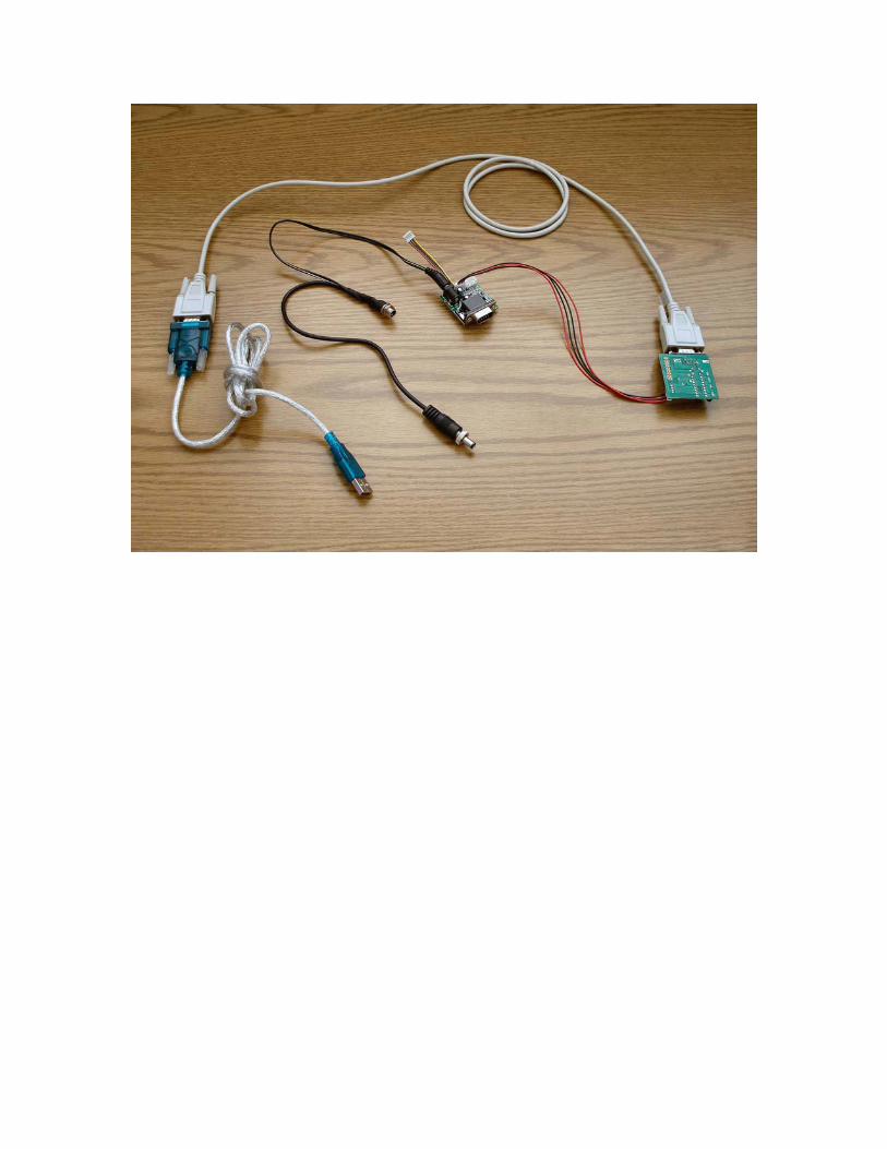
Photographs