technical tesys gv, gb designers data for¡logos/schneider/b6 - circuit... · circuit breaker type...
TRANSCRIPT
B6/57
Technical Data for Designers
TeS
ys G
V, G
B
ContentsTeSys GV2: > characteristics .....................................B6/60 to B6/64 > curves ..................................................B6/65 to B6/74 > accessories ..........................................B6/75 to B6/76 > dimensions, schemes ..........................B6/78 to B6/87
TeSys GV3: > characteristics .....................................B6/90 to B6/93 > curves ..................................................B6/94 to B6/99 > accessories ......................................B6/100 to B6/102 > dimensions, schemes ......................B6/103 to B6/105
TeSys GV4: > characteristics .................................B6/108 to B6/120 > curves ..............................................B6/113 to B6/119 > accessories ......................................B6/120 to B6/121 > dimensions ......................................B6/122 to B6/124
TeSys GV7: > characteristics .................................................B6/128 > curves ..............................................B6/129 to B6/133 > accessories ......................................B6/134 to B6/135 > dimensions, schemes ......................B6/136 to B6/139
TeSys GVB2: > characteristics .................................B6/142 to B6/144 > dimensions, schemes ......................................B6/145
Circ
uit
brea
kers

B6/58
Circ
uit
brea
kers
B6/59
TeSys GV20.06 to 15 kW
Circ
uit
brea
kers
B6/60
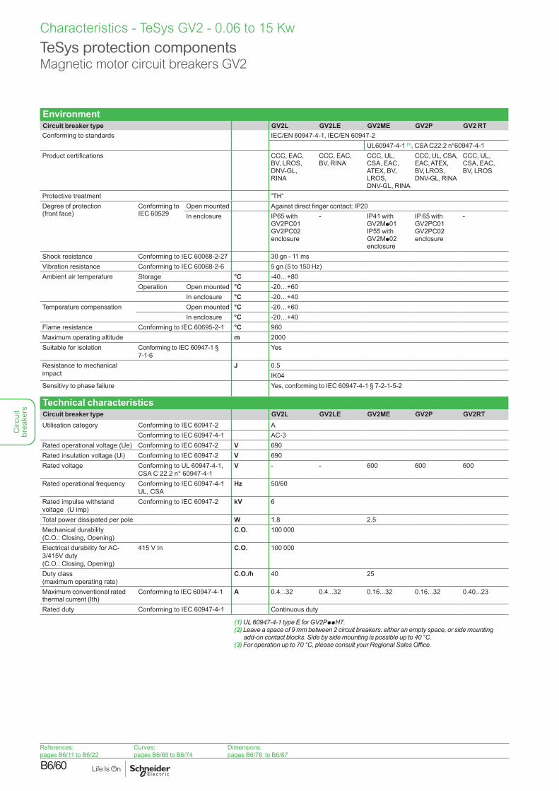
Characteristics - TeSys GV2 - 0.06 to 15 Kw
TeSys protection componentsMagnetic motor circuit breakers GV2
EnvironmentCircuit breaker type GV2L GV2LE GV2ME GV2P GV2 RTConforming to standards IEC/EN 60947-4-1, IEC/EN 60947-2
UL60947-4-1 (1), CSA C22.2 n°60947-4-1Product certifications CCC, EAC,
BV, LROS,DNV-GL, RINA
CCC, EAC, BV, RINA
CCC, UL, CSA, EAC, ATEX, BV, LROS, DNV-GL, RINA
CCC, UL, CSA, EAC, ATEX, BV, LROS, DNV-GL, RINA
CCC, UL, CSA, EAC, BV, LROS
Protective treatment "TH"
Degree of protection (front face)
Conforming to IEC 60529
Open mounted Against direct finger contact: IP20In enclosure IP65 with
GV2PC01GV2PC02 enclosure
- IP41 withGV2Mp01IP55 withGV2Mp02enclosure
IP 65 withGV2PC01GV2PC02 enclosure
-
Shock resistance Conforming to IEC 60068-2-27 30 gn - 11 msVibration resistance Conforming to IEC 60068-2-6 5 gn (5 to 150 Hz)Ambient air temperature Storage °C -40…+80
Operation Open mounted °C -20…+60In enclosure °C -20…+40
Temperature compensation Open mounted °C -20…+60In enclosure °C -20…+40
Flame resistance Conforming to IEC 60695-2-1 °C 960Maximum operating altitude m 2000Suitable for isolation Conforming to IEC 60947-1 §
7-1-6Yes
Resistance to mechanical impact
J 0.5IK04
Sensitivy to phase failure Yes, conforming to IEC 60947-4-1 § 7-2-1-5-2
Technical characteristicsCircuit breaker type GV2L GV2LE GV2ME GV2P GV2RTUtilisation category Conforming to IEC 60947-2 A
Conforming to IEC 60947-4-1 AC-3Rated operational voltage (Ue) Conforming to IEC 60947-2 V 690Rated insulation voltage (Ui) Conforming to IEC 60947-2 V 690Rated voltage Conforming to UL 60947-4-1,
CSA C 22.2 n° 60947-4-1V - - 600 600 600
Rated operational frequency Conforming to IEC 60947-4-1 UL, CSA
Hz 50/60
Rated impulse withstand voltage (U imp)
Conforming to IEC 60947-2 kV 6
Total power dissipated per pole W 1.8 2.5Mechanical durability (C.O.: Closing, Opening)
C.O. 100 000
Electrical durability for AC-3/415V duty (C.O.: Closing, Opening)
415 V In C.O. 100 000
Duty class (maximum operating rate)
C.O./h 40 25
Maximum conventional rated thermal current (Ith)
Conforming to IEC 60947-4-1 A 0.4...32 0.4...32 0.16...32 0.16...32 0.40...23
Rated duty Conforming to IEC 60947-4-1 Continuous duty
(1) UL 60947-4-1 type E for GV2PppH7.(2) Leave a space of 9 mm between 2 circuit breakers: either an empty space, or side mounting
add-on contact blocks. Side by side mounting is possible up to 40 °C.(3) For operation up to 70 °C, please consult your Regional Sales Office.
References:pages B6/11 to B6/22
Curves:pages B6/65 to B6/74
Dimensions:pages B6/78 to B6/87
Circ
uit
brea
kers
B6/61
Characteristics - TeSys GV2 - 0.06 to 15 Kw
TeSys protection componentsMagnetic motor circuit breakers GV2
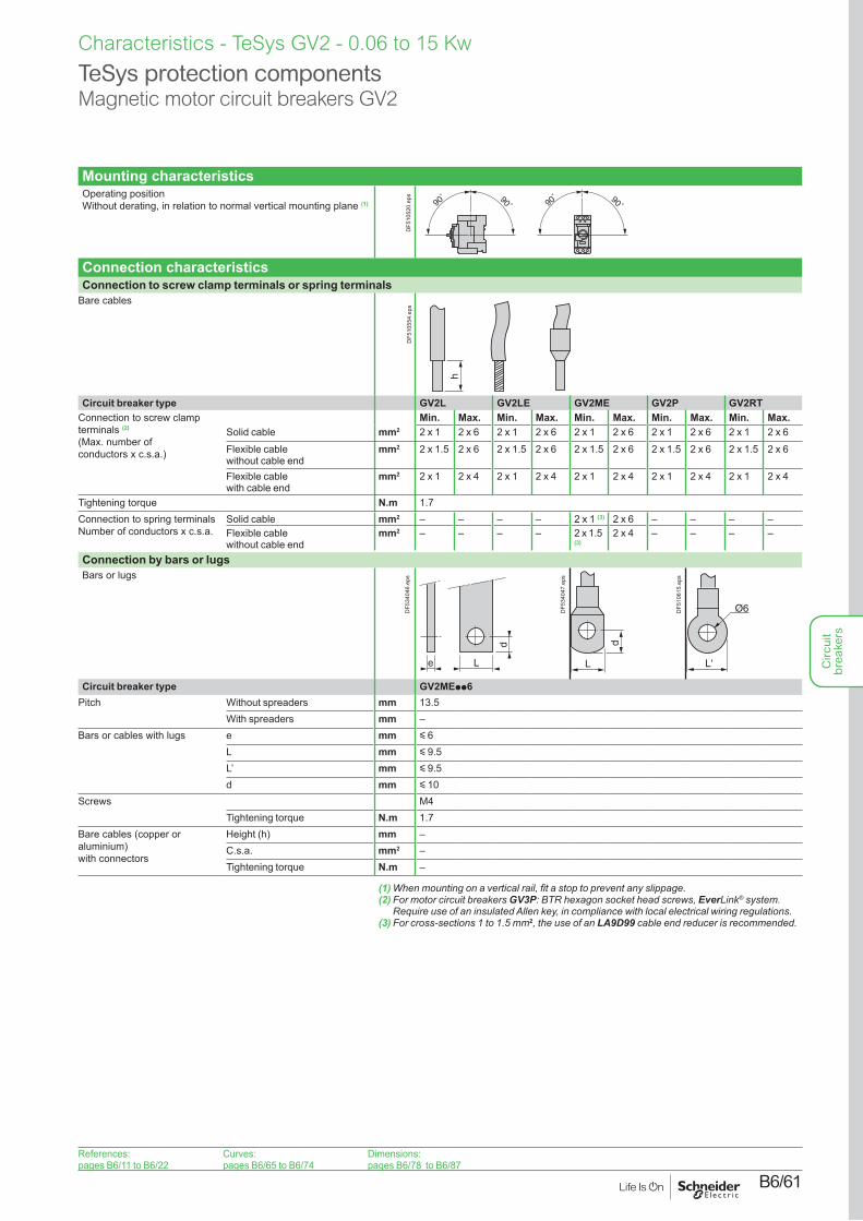
Mounting characteristicsOperating position Without derating, in relation to normal vertical mounting plane (1) 90
˚ 90˚90˚ 90˚
DF5
1052
0.ep
s
Connection characteristicsConnection to screw clamp terminals or spring terminals
Bare cables
h
DF5
1055
4.ep
sCircuit breaker type GV2L GV2LE GV2ME GV2P GV2RT
Connection to screw clamp terminals (2) (Max. number of conductors x c.s.a.)
Min. Max. Min. Max. Min. Max. Min. Max. Min. Max.Solid cable mm2 2 x 1 2 x 6 2 x 1 2 x 6 2 x 1 2 x 6 2 x 1 2 x 6 2 x 1 2 x 6Flexible cable without cable end
mm2 2 x 1.5 2 x 6 2 x 1.5 2 x 6 2 x 1.5 2 x 6 2 x 1.5 2 x 6 2 x 1.5 2 x 6
Flexible cable with cable end
mm2 2 x 1 2 x 4 2 x 1 2 x 4 2 x 1 2 x 4 2 x 1 2 x 4 2 x 1 2 x 4
Tightening torque N.m 1.7Connection to spring terminals Number of conductors x c.s.a.
Solid cable mm2 – – – – 2 x 1 (3) 2 x 6 – – – –Flexible cable without cable end
mm2 – – – – 2 x 1.5 (3)
2 x 4 – – – –
Connection by bars or lugsBars or lugs
e
d
L
DF5
3404
6.ep
s
d
L
DF5
3404
7.ep
s
L'
Ø6DF5
1061
5.ep
s
Circuit breaker type GV2MEpp6Pitch Without spreaders mm 13.5
With spreaders mm –Bars or cables with lugs e mm y 6
L mm y 9.5L’ mm y 9.5d mm y 10
Screws M4Tightening torque N.m 1.7
Bare cables (copper or aluminium) with connectors
Height (h) mm –C.s.a. mm2 –Tightening torque N.m –
(1) When mounting on a vertical rail, fit a stop to prevent any slippage.(2) For motor circuit breakers GV3P: BTR hexagon socket head screws, EverLink® system.
Require use of an insulated Allen key, in compliance with local electrical wiring regulations.(3) For cross-sections 1 to 1.5 mm2, the use of an LA9D99 cable end reducer is recommended.
References:pages B6/11 to B6/22
Curves:pages B6/65 to B6/74
Dimensions:pages B6/78 to B6/87
Circ
uit
brea
kers
B6/62
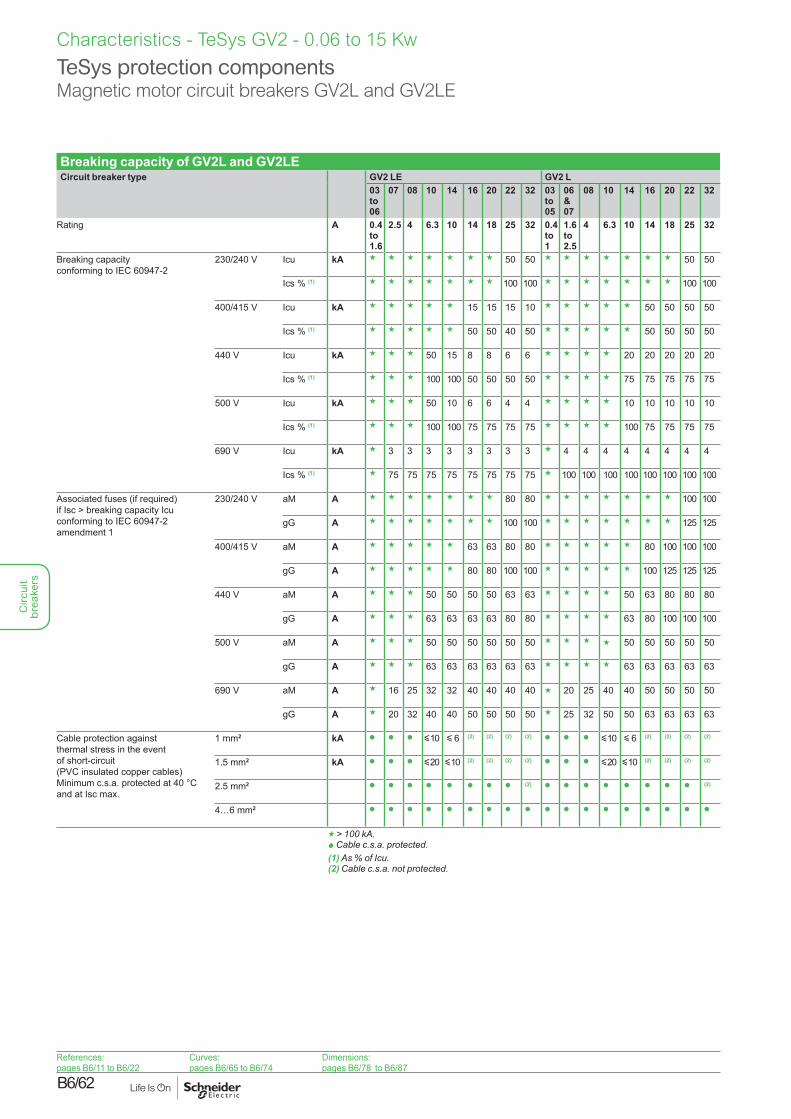
Breaking capacity of GV2L and GV2LECircuit breaker type GV2 LE GV2 L
03 to 06
07 08 10 14 16 20 22 32 03 to 05
06 &07
08 10 14 16 20 22 32
Rating A 0.4 to 1.6
2.5 4 6.3 10 14 18 25 32 0.4 to 1
1.6 to 2.5
4 6.3 10 14 18 25 32
Breaking capacity conforming to IEC 60947-2
230/240 V Icu kA g g g g g g g 50 50 g g g g g g g 50 50
Ics % (1) g g g g g g g 100 100 g g g g g g g 100 100
400/415 V Icu kA g g g g g 15 15 15 10 g g g g g 50 50 50 50
Ics % (1) g g g g g 50 50 40 50 g g g g g 50 50 50 50
440 V Icu kA g g g 50 15 8 8 6 6 g g g g 20 20 20 20 20
Ics % (1) g g g 100 100 50 50 50 50 g g g g 75 75 75 75 75
500 V Icu kA g g g 50 10 6 6 4 4 g g g g 10 10 10 10 10
Ics % (1) g g g 100 100 75 75 75 75 g g g g 100 75 75 75 75
690 V Icu kA g 3 3 3 3 3 3 3 3 g 4 4 4 4 4 4 4 4
Ics % (1) g 75 75 75 75 75 75 75 75 g 100 100 100 100 100 100 100 100
Associated fuses (if required) if Isc > breaking capacity Icu conforming to IEC 60947-2 amendment 1
230/240 V aM A g g g g g g g 80 80 g g g g g g g 100 100
gG A g g g g g g g 100 100 g g g g g g g 125 125
400/415 V aM A g g g g g 63 63 80 80 g g g g g 80 100 100 100
gG A g g g g g 80 80 100 100 g g g g g 100 125 125 125
440 V aM A g g g 50 50 50 50 63 63 g g g g 50 63 80 80 80
gG A g g g 63 63 63 63 80 80 g g g g 63 80 100 100 100
500 V aM A g g g 50 50 50 50 50 50 g g g g 50 50 50 50 50
gG A g g g 63 63 63 63 63 63 g g g g 63 63 63 63 63
690 V aM A g 16 25 32 32 40 40 40 40 g 20 25 40 40 50 50 50 50
gG A g 20 32 40 40 50 50 50 50 g 25 32 50 50 63 63 63 63
Cable protection against thermal stress in the event of short-circuit (PVC insulated copper cables) Minimum c.s.a. protected at 40 °C and at Isc max.
1 mm2 kA p p p y 10 y 6 (2) (2) (2) (2) p p p y 10 y 6 (2) (2) (2) (2)
1.5 mm2 kA p p p y 20 y 10 (2) (2) (2) (2) p p p y 20 y 10 (2) (2) (2) (2)
2.5 mm2 p p p p p p p p (2) p p p p p p p p (2)
4…6 mm2 p p p p p p p p p p p p p p p p p p
g > 100 kA.p Cable c.s.a. protected.(1) As % of Icu.(2) Cable c.s.a. not protected.
Characteristics - TeSys GV2 - 0.06 to 15 Kw
TeSys protection componentsMagnetic motor circuit breakers GV2L and GV2LE
References:pages B6/11 to B6/22
Curves:pages B6/65 to B6/74
Dimensions:pages B6/78 to B6/87
Circ
uit
brea
kers
B6/63
Characteristics - TeSys GV2 - 0.06 to 15 Kw
TeSys protection componentsThermal-magnetic motor circuit breakers GV2ME and GV2P
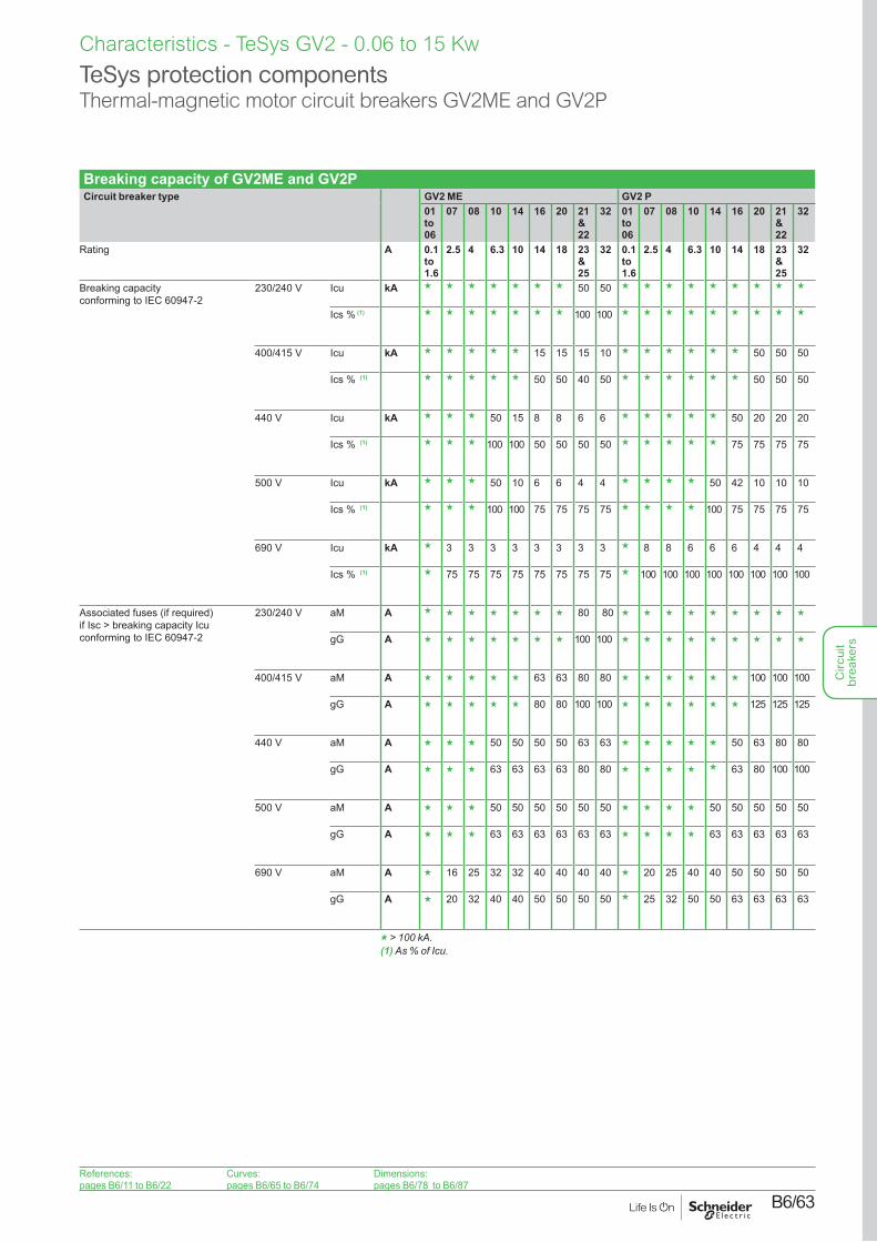
Breaking capacity of GV2ME and GV2PCircuit breaker type GV2 ME GV2 P
01 to 06
07 08 10 14 16 20 21 & 22
32 01 to 06
07 08 10 14 16 20 21 & 22
32
Rating A 0.1 to 1.6
2.5 4 6.3 10 14 18 23 & 25
32 0.1 to 1.6
2.5 4 6.3 10 14 18 23 & 25
32
Breaking capacity conforming to IEC 60947-2
230/240 V Icu kA g g g g g g g 50 50 g g g g g g g g g
Ics % (1) g g g g g g g 100 100 g g g g g g g g g
400/415 V Icu kA g g g g g 15 15 15 10 g g g g g g 50 50 50
Ics % (1) g g g g g 50 50 40 50 g g g g g g 50 50 50
440 V Icu kA g g g 50 15 8 8 6 6 g g g g g 50 20 20 20
Ics % (1) g g g 100 100 50 50 50 50 g g g g g 75 75 75 75
500 V Icu kA g g g 50 10 6 6 4 4 g g g g 50 42 10 10 10
Ics % (1) g g g 100 100 75 75 75 75 g g g g 100 75 75 75 75
690 V Icu kA g 3 3 3 3 3 3 3 3 g 8 8 6 6 6 4 4 4
Ics % (1) g 75 75 75 75 75 75 75 75 g 100 100 100 100 100 100 100 100
Associated fuses (if required) if Isc > breaking capacity Icu conforming to IEC 60947-2
230/240 V aM A g g g g g g g 80 80 g g g g g g g g g
gG A g g g g g g g 100 100 g g g g g g g g g
400/415 V aM A g g g g g 63 63 80 80 g g g g g g 100 100 100
gG A g g g g g 80 80 100 100 g g g g g g 125 125 125
440 V aM A g g g 50 50 50 50 63 63 g g g g g 50 63 80 80
gG A g g g 63 63 63 63 80 80 g g g g g 63 80 100 100
500 V aM A g g g 50 50 50 50 50 50 g g g g 50 50 50 50 50
gG A g g g 63 63 63 63 63 63 g g g g 63 63 63 63 63
690 V aM A g 16 25 32 32 40 40 40 40 g 20 25 40 40 50 50 50 50
gG A g 20 32 40 40 50 50 50 50 g 25 32 50 50 63 63 63 63
g > 100 kA.(1) As % of Icu.
References:pages B6/11 to B6/22
Curves:pages B6/65 to B6/74
Dimensions:pages B6/78 to B6/87
Circ
uit
brea
kers
B6/64
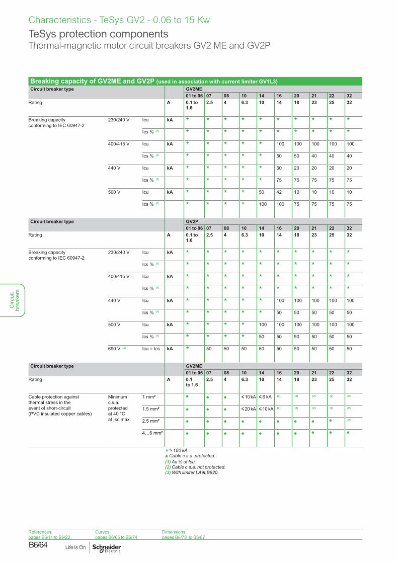
Breaking capacity of GV2ME and GV2P (used in association with current limiter GV1L3)Circuit breaker type GV2ME
01 to 06 07 08 10 14 16 20 21 22 32Rating A 0.1 to
1.62.5 4 6.3 10 14 18 23 25 32
Breaking capacity conforming to IEC 60947-2
230/240 V Icu kA g g g g g g g g g g
Ics % (1) g g g g g g g g g g
400/415 V Icu kA g g g g g 100 100 100 100 100
Ics % (1) g g g g g 50 50 40 40 40
440 V Icu kA g g g g g 50 20 20 20 20
Ics % (1) g g g g g 75 75 75 75 75
500 V Icu kA g g g g 50 42 10 10 10 10
Ics % (1) g g g g 100 100 75 75 75 75
Circuit breaker type GV2P01 to 06 07 08 10 14 16 20 21 22 32
Rating A 0.1 to 1.6
2.5 4 6.3 10 14 18 23 25 32
Breaking capacity conforming to IEC 60947-2
230/240 V Icu kA g g g g g g g g g g
Ics % (1) g g g g g g g g g g
400/415 V Icu kA g g g g g g g g g g
Ics % (1) g g g g g g g g g g
440 V Icu kA g g g g g 100 100 100 100 100
Ics % (1) g g g g g 50 50 50 50 50
500 V Icu kA g g g g 100 100 100 100 100 100
Ics % (1) g g g g 50 50 50 50 50 50
690 V (3) Icu = Ics kA g 50 50 50 50 50 50 50 50 50
Circuit breaker type GV2ME01 to 06 07 08 10 14 16 20 21 22 32
Rating A 0.1 to 1.6
2.5 4 6.3 10 14 18 23 25 32
Cable protection against thermal stress in the event of short-circuit (PVC insulated copper cables)
Minimum c.s.a. protected at 40 °C at Isc max.
1 mm2 p p p y 10 kA y 6 kA (2) (2) (2) (2) (2)
1.5 mm2 p p p y 20 kA y 10 kA (2) (2) (2) (2) (2)
2.5 mm2 p p p p p p p p p (2)
4…6 mm2 p p p p p p p p p p
g > 100 kA.p Cable c.s.a. protected.(1) As % of Icu.(2) Cable c.s.a. not protected.(3) With limiter LA9LB920.
Characteristics - TeSys GV2 - 0.06 to 15 Kw
TeSys protection componentsThermal-magnetic motor circuit breakers GV2 ME and GV2P
References:pages B6/11 to B6/22
Curves:pages B6/65 to B6/74
Dimensions:pages B6/78 to B6/87
Circ
uit
brea
kers
B6/65
Curves - TeSys GV2 - 0.06 to 15 kW
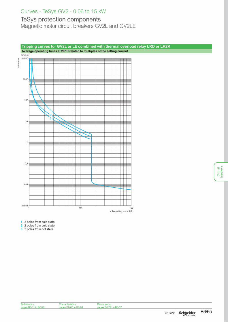
Tripping curves for GV2L or LE combined with thermal overload relay LRD or LR2KAverage operating times at 20 °C related to multiples of the setting current
10
10 000
1
0,1
0,0011 10 100
1000
100
0,01
321
Time (s)
x the setting current (Ir)
DF5
3409
2R.e
ps
1 3 poles from cold state2 2 poles from cold state3 3 poles from hot state
TeSys protection componentsMagnetic motor circuit breakers GV2L and GV2LE
References:pages B6/11 to B6/22
Characteristics:pages B6/60 to B6/64
Dimensions:pages B6/78 to B6/87
Circ
uit
brea
kers
B6/66
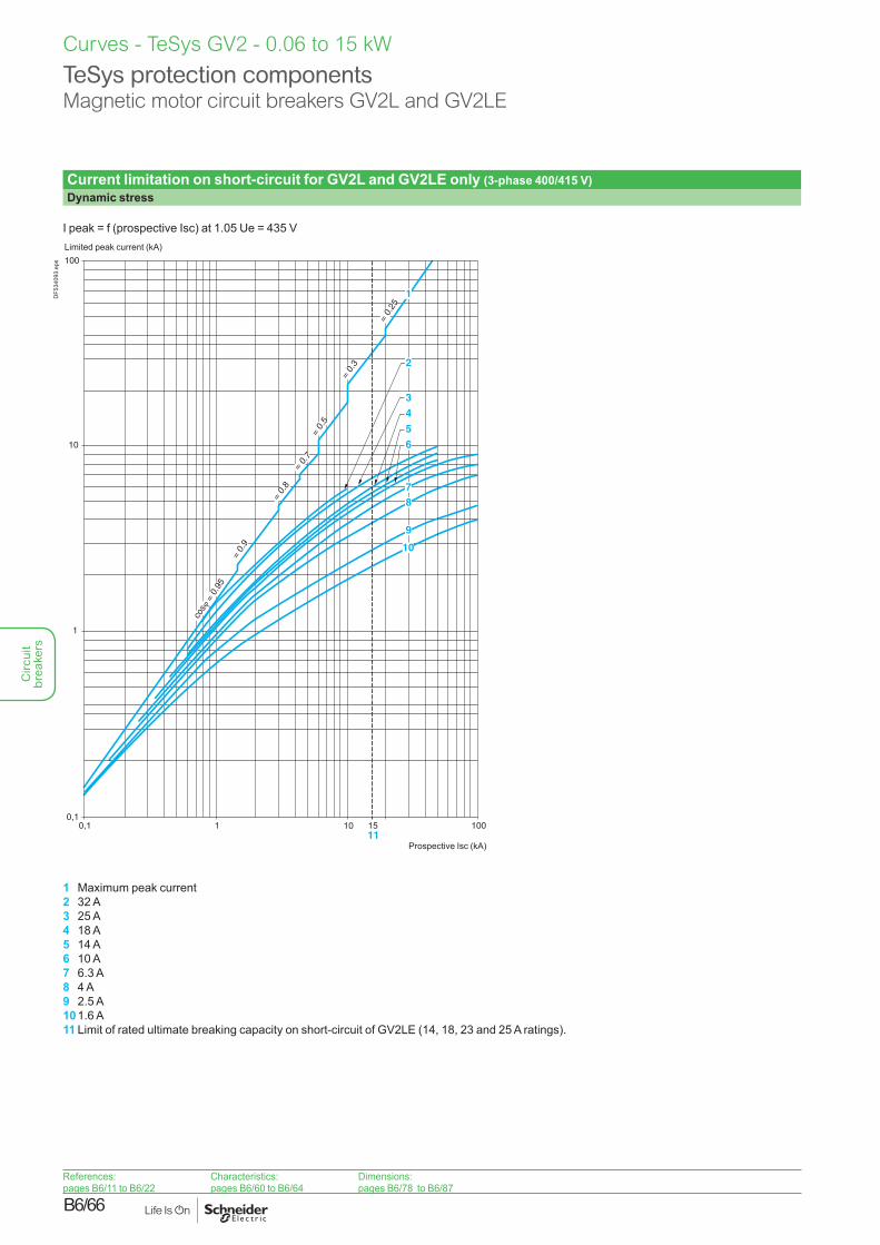
Current limitation on short-circuit for GV2L and GV2LE only (3-phase 400/415 V)Dynamic stress
I peak = f (prospective Isc) at 1.05 Ue = 435 V
100
10
1
0,10,1 1 100
1
5
4
3
8
9
10
7
6
cos
= 0
.95
= 0.
9
= 0.
8
= 0.7
= 0.
5
= 0.
3
= 0.
25
151011
2
Limited peak current (kA)
Prospective Isc (kA)
DF5
3409
3.ep
s
1 Maximum peak current2 32 A3 25 A4 18 A5 14 A6 10 A7 6.3 A8 4 A9 2.5 A10 1.6 A11 Limit of rated ultimate breaking capacity on short-circuit of GV2LE (14, 18, 23 and 25 A ratings).
Curves - TeSys GV2 - 0.06 to 15 kW
TeSys protection componentsMagnetic motor circuit breakers GV2L and GV2LE
References:pages B6/11 to B6/22
Characteristics:pages B6/60 to B6/64
Dimensions:pages B6/78 to B6/87
Circ
uit
brea
kers
B6/67
Curves - TeSys GV2 - 0.06 to 15 kW
TeSys protection componentsMagnetic motor circuit breakers GV2L and GV2LE
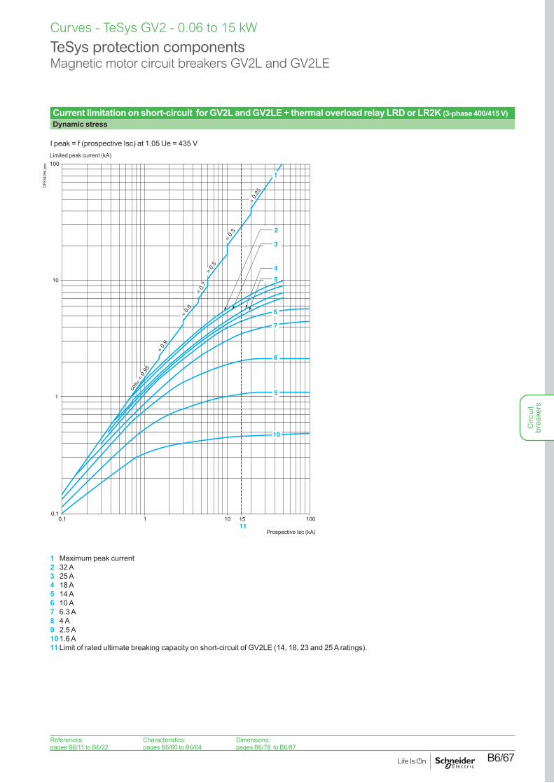
Current limitation on short-circuit for GV2L and GV2LE + thermal overload relay LRD or LR2K (3-phase 400/415 V)Dynamic stress
I peak = f (prospective Isc) at 1.05 Ue = 435 V
100
10
1
0,10,1 1 10 100
cos
= 0
.95
= 0.
9
= 0.
8
= 0.
7=
0.5
= 0.
3
= 0.
25
15 11
1
2
3
4
5
6
7
8
9
10
Limited peak current (kA)
Prospective Isc (kA)
DF5
3409
4.ep
s
1 Maximum peak current2 32 A3 25 A4 18 A5 14 A6 10 A7 6.3 A8 4 A9 2.5 A10 1.6 A11 Limit of rated ultimate breaking capacity on short-circuit of GV2LE (14, 18, 23 and 25 A ratings).
References:pages B6/11 to B6/22
Characteristics:pages B6/60 to B6/64
Dimensions:pages B6/78 to B6/87
Circ
uit
brea
kers
B6/68
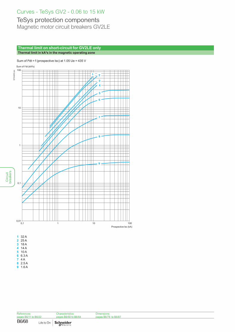
Thermal limit on short-circuit for GV2LE onlyThermal limit in kA2s in the magnetic operating zone
Sum of I2dt = f (prospective Isc) at 1.05 Ue = 435 V
100
10
1
0,1
0,010,1 1 10 100
1 2
3
4
5
6
7
8
9
Sum of I2dt (kA2s)
Prospective Isc (kA)
DF5
3409
5.ep
s
1 32 A2 25 A3 18 A4 14 A5 10 A6 6.3 A7 4 A8 2.5 A9 1.6 A
Curves - TeSys GV2 - 0.06 to 15 kW
TeSys protection componentsMagnetic motor circuit breakers GV2LE
References:pages B6/11 to B6/22
Characteristics:pages B6/60 to B6/64
Dimensions:pages B6/78 to B6/87
Circ
uit
brea
kers
B6/69
Curves - TeSys GV2 - 0.06 to 15 kW
TeSys protection componentsMagnetic motor circuit breakers GV2L
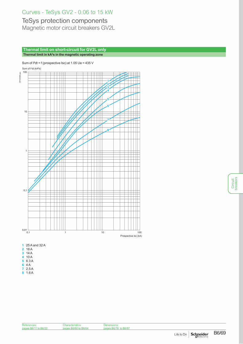
Thermal limit on short-circuit for GV2L onlyThermal limit in kA2s in the magnetic operating zone
Sum of I2dt = f (prospective Isc) at 1.05 Ue = 435 V
100
10
1
0,1
0,010,1 1 10 100
1234
5
6
8
7
Sum of I2dt (kA2s)
Prospective Isc (kA)
DF5
3409
6.ep
s
1 25 A and 32 A2 18 A3 14 A4 10 A5 6.3 A6 4 A7 2.5 A8 1.6 A
References:pages B6/11 to B6/22
Characteristics:pages B6/60 to B6/64
Dimensions:pages B6/78 to B6/87
Circ
uit
brea
kers
B6/70
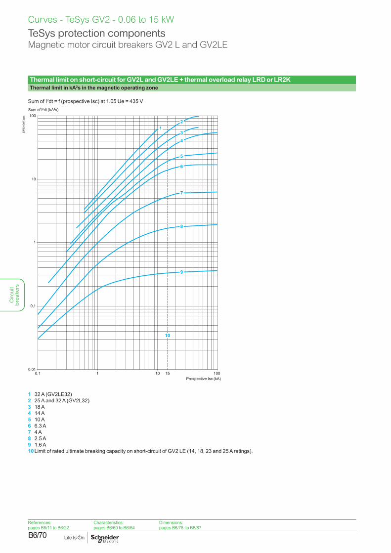
Thermal limit on short-circuit for GV2L and GV2LE + thermal overload relay LRD or LR2KThermal limit in kA2s in the magnetic operating zone
Sum of I2dt = f (prospective Isc) at 1.05 Ue = 435 V
100
10
1
0,1
0,010,1 1 10 100
2
3
4
5
6
7
8
9
15
1
10
Sum of I2dt (kA2s)
Prospective Isc (kA)
DF5
3409
7.ep
s
1 32 A (GV2LE32)2 25 A and 32 A (GV2L32)3 18 A4 14 A5 10 A6 6.3 A7 4 A8 2.5 A9 1.6 A10 Limit of rated ultimate breaking capacity on short-circuit of GV2 LE (14, 18, 23 and 25 A ratings).
Curves - TeSys GV2 - 0.06 to 15 kW
TeSys protection componentsMagnetic motor circuit breakers GV2 L and GV2LE
References:pages B6/11 to B6/22
Characteristics:pages B6/60 to B6/64
Dimensions:pages B6/78 to B6/87
Circ
uit
brea
kers
B6/71
Curves - TeSys GV2 - 0.06 to 15 kW
TeSys protection componentsThermal-magnetic motor circuit breakers GV2ME and GV2P
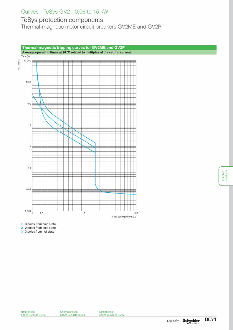
Thermal-magnetic tripping curves for GV2ME and GV2PAverage operating times at 20 °C related to multiples of the setting current
0,001
0,1
1
10
100
0,01
1 1,5 10 100
1000
10 000
3
2
1
Time (s)
x the setting current (Ir)
DF5
3407
5R.a
i
1 3 poles from cold state2 2 poles from cold state3 3 poles from hot state
References:pages B6/11 to B6/22
Characteristics:pages B6/60 to B6/64
Dimensions:pages B6/78 to B6/87
Circ
uit
brea
kers
B6/72
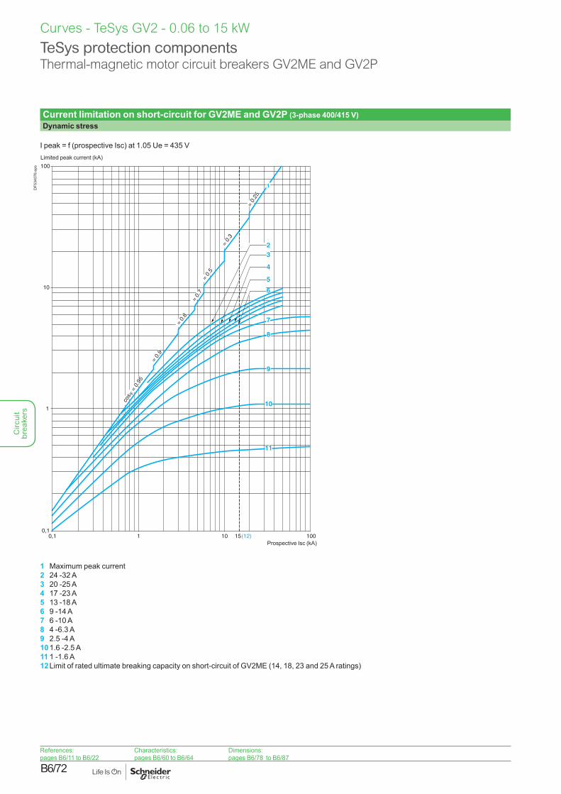
Current limitation on short-circuit for GV2ME and GV2P (3-phase 400/415 V)Dynamic stress
I peak = f (prospective Isc) at 1.05 Ue = 435 V
1
6
5
4
3
7
8
9
10
11
2
100
10
1
0,10,1 1 10 100
cos
= 0
.95
= 0.
9
= 0.
8
= 0.
7=
0.5
= 0.
3
= 0.
25
15 (12)
Limited peak current (kA)
Prospective Isc (kA)
DF5
3407
6.ep
s
1 Maximum peak current2 24 -32 A3 20 -25 A4 17 -23 A5 13 -18 A6 9 -14 A7 6 -10 A8 4 -6.3 A9 2.5 -4 A10 1.6 -2.5 A11 1 -1.6 A12 Limit of rated ultimate breaking capacity on short-circuit of GV2ME (14, 18, 23 and 25 A ratings)
Curves - TeSys GV2 - 0.06 to 15 kW
TeSys protection componentsThermal-magnetic motor circuit breakers GV2ME and GV2P
References:pages B6/11 to B6/22
Characteristics:pages B6/60 to B6/64
Dimensions:pages B6/78 to B6/87
Circ
uit
brea
kers
B6/73
Curves - TeSys GV2 - 0.06 to 15 kW
TeSys protection componentsThermal-magnetic motor circuit breakers GV2ME
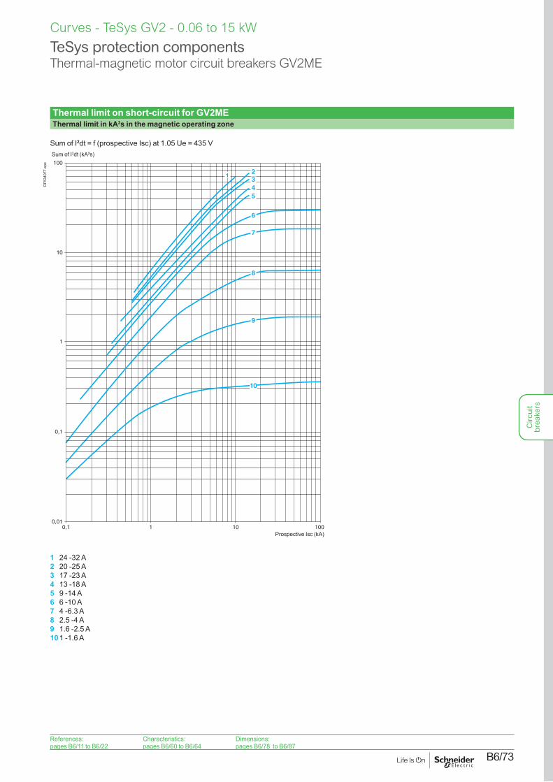
Thermal limit on short-circuit for GV2METhermal limit in kA2s in the magnetic operating zone
Sum of I2dt = f (prospective Isc) at 1.05 Ue = 435 V
100
10
1
0,1
0,010,1 1 10 100
345
6
7
8
9
10
21
Sum of I2dt (kA2s)
Prospective Isc (kA)
DF5
3407
7.ep
s
1 24 -32 A2 20 -25 A3 17 -23 A4 13 -18 A5 9 -14 A6 6 -10 A7 4 -6.3 A8 2.5 -4 A9 1.6 -2.5 A10 1 -1.6 A
References:pages B6/11 to B6/22
Characteristics:pages B6/60 to B6/64
Dimensions:pages B6/78 to B6/87
Circ
uit
brea
kers
B6/74
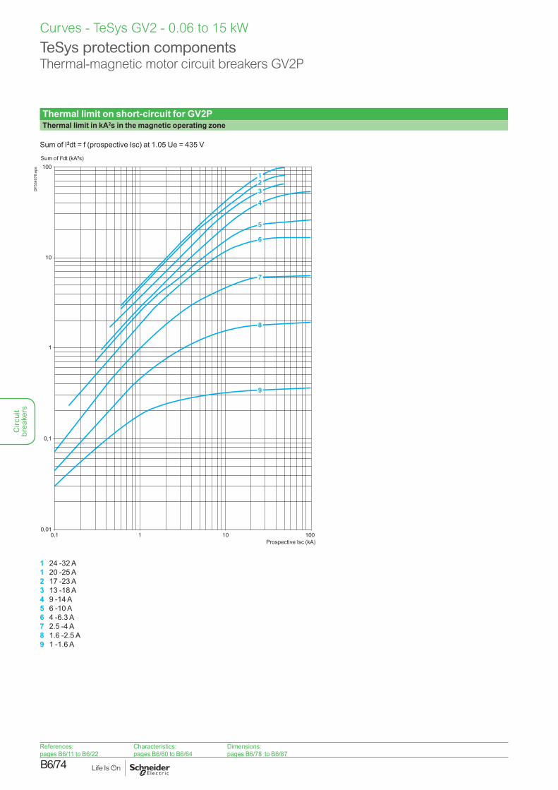
Thermal limit on short-circuit for GV2PThermal limit in kA2s in the magnetic operating zone
Sum of I2dt = f (prospective Isc) at 1.05 Ue = 435 V
100
10
1
0,1
0,010,1 1 10 100
123
4
5
6
7
8
9
Sum of I2dt (kA2s)
Prospective Isc (kA)
DF5
3407
8.ep
s
1 24 -32 A1 20 -25 A2 17 -23 A3 13 -18 A4 9 -14 A5 6 -10 A6 4 -6.3 A7 2.5 -4 A8 1.6 -2.5 A9 1 -1.6 A
Curves - TeSys GV2 - 0.06 to 15 kW
TeSys protection componentsThermal-magnetic motor circuit breakers GV2P
References:pages B6/11 to B6/22
Characteristics:pages B6/60 to B6/64
Dimensions:pages B6/78 to B6/87
Circ
uit
brea
kers
B6/75
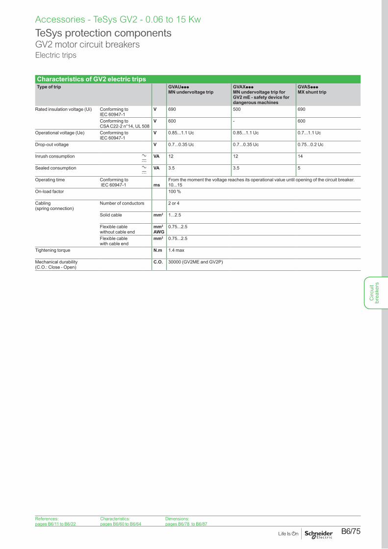
Characteristics of GV2 electric tripsType of trip GVAUppp
MN undervoltage tripGVAXpppMN undervoltage trip for GV2 mE - safety device for dangerous machines
GVASppp MX shunt trip
Rated insulation voltage (Ui) Conforming to IEC 60947-1
V 690 500 690
Conforming to CSA C22-2 n°14, UL 508
V 600 - 600
Operational voltage (Ue) Conforming to IEC 60947-1
V 0.85...1.1 Uc 0.85...1.1 Uc 0.7...1.1 Uc
Drop-out voltage V 0.7...0.35 Uc 0.7...0.35 Uc 0.75...0.2 Uc
Inrush consumption a c
VA 12 12 14
Sealed consumption a c
VA 3.5 3.5 5
Operating time Conforming to IEC 60947-1 ms
From the moment the voltage reaches its operational value until opening of the circuit breaker. 10...15
On-load factor 100 %
Cabling (spring connection)
Number of conductors 2 or 4
Solid cable mm2 1...2.5
Flexible cable without cable end
mm2
AWG0.75...2.5
Flexible cable with cable end
mm2 0.75...2.5
Tightening torque N.m 1.4 max
Mechanical durability (C.O.: Close - Open)
C.O. 30000 (GV2ME and GV2P)
TeSys protection componentsGV2 motor circuit breakersElectric trips
Accessories - TeSys GV2 - 0.06 to 15 Kw
References:pages B6/11 to B6/22
Characteristics:pages B6/60 to B6/64
Dimensions:pages B6/78 to B6/87
Circ
uit
brea
kers
B6/76
Accessories - TeSys GV2 - 0.06 to 15 Kw
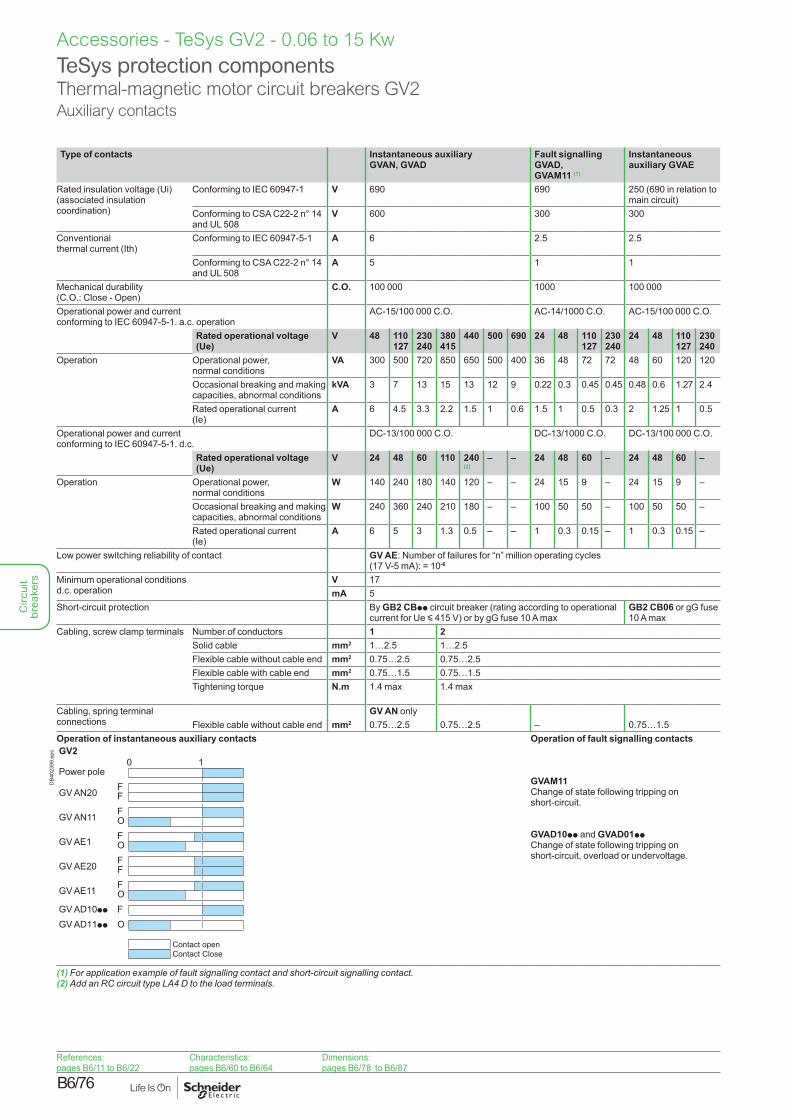
Type of contacts Instantaneous auxiliary GVAN, GVAD
Fault signalling GVAD, GVAM11 (1)
Instantaneous auxiliary GVAE
Rated insulation voltage (Ui) (associated insulation coordination)
Conforming to IEC 60947-1 V 690 690 250 (690 in relation to main circuit)
Conforming to CSA C22-2 n° 14 and UL 508
V 600 300 300
Conventional thermal current (Ith)
Conforming to IEC 60947-5-1 A 6 2.5 2.5
Conforming to CSA C22-2 n° 14 and UL 508
A 5 1 1
Mechanical durability (C.O.: Close - Open)
C.O. 100 000 1000 100 000
Operational power and current conforming to IEC 60947-5-1. a.c. operation
AC-15/100 000 C.O. AC-14/1000 C.O. AC-15/100 000 C.O.
Rated operational voltage (Ue)
V 48 110 127
230 240
380 415
440 500 690 24 48 110 127
230 240
24 48 110 127
230 240
Operation Operational power, normal conditions
VA 300 500 720 850 650 500 400 36 48 72 72 48 60 120 120
Occasional breaking and making capacities, abnormal conditions
kVA 3 7 13 15 13 12 9 0.22 0.3 0.45 0.45 0.48 0.6 1.27 2.4
Rated operational current (Ie)
A 6 4.5 3.3 2.2 1.5 1 0.6 1.5 1 0.5 0.3 2 1.25 1 0.5
Operational power and current conforming to IEC 60947-5-1. d.c.
DC-13/100 000 C.O. DC-13/1000 C.O. DC-13/100 000 C.O.
Rated operational voltage (Ue)
V 24 48 60 110 240(2)
– – 24 48 60 – 24 48 60 –
Operation Operational power, normal conditions
W 140 240 180 140 120 – – 24 15 9 – 24 15 9 –
Occasional breaking and making capacities, abnormal conditions
W 240 360 240 210 180 – – 100 50 50 – 100 50 50 –
Rated operational current (Ie)
A 6 5 3 1.3 0.5 – – 1 0.3 0.15 – 1 0.3 0.15 –
Low power switching reliability of contact GV AE: Number of failures for “n” million operating cycles (17 V-5 mA): = 10-6
Minimum operational conditions d.c. operation
V 17mA 5
Short-circuit protection By GB2 CBpp circuit breaker (rating according to operational current for Ue y 415 V) or by gG fuse 10 A max
GB2 CB06 or gG fuse 10 A max
Cabling, screw clamp terminals Number of conductors 1 2Solid cable mm2 1…2.5 1…2.5Flexible cable without cable end mm2 0.75…2.5 0.75…2.5Flexible cable with cable end mm2 0.75…1.5 0.75…1.5Tightening torque N.m 1.4 max 1.4 max
Cabling, spring terminal connections
GV AN onlyFlexible cable without cable end mm2 0.75…2.5 0.75…2.5 – 0.75…1.5
Operation of instantaneous auxiliary contactsGV3P, GV3L
0 1Power pole
GV AN20 FF
GV AN11 FO
GV AE1 FO
GV AE20 FF
GV AE11 FO
GV AD10pp FO
GV AED101 FGV AED011 O
GV20 1
Power pole
GV AN20 FF
GV AN11 FO
GV AE1 FO
GV AE20 FF
GV AE11 FO
GV AD10pp FGV AD11pp O
Contact open Contact Close
DB4
0239
9.ep
s
Operation of fault signalling contacts
GVAM11Change of state following tripping on short-circuit.
GVAD10pp and GVAD01ppChange of state following tripping on short-circuit, overload or undervoltage.
(1) For application example of fault signalling contact and short-circuit signalling contact.(2) Add an RC circuit type LA4 D to the load terminals.
TeSys protection componentsThermal-magnetic motor circuit breakers GV2Auxiliary contacts
References:pages B6/11 to B6/22
Characteristics:pages B6/60 to B6/64
Dimensions:pages B6/78 to B6/87
Circ
uit
brea
kers
B6/77
Characteristics - TeSys GV2 - 0.06 to 15 Kw
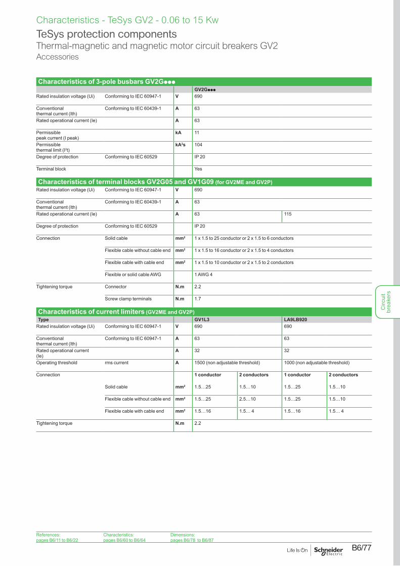
Characteristics of 3-pole busbars GV2GpppGV2Gppp
Rated insulation voltage (Ui) Conforming to IEC 60947-1 V 690
Conventional thermal current (Ith)
Conforming to IEC 60439-1 A 63
Rated operational current (Ie) A 63
Permissible peak current (I peak)
kA 11
Permissible thermal limit (I2t)
kA2s 104
Degree of protection Conforming to IEC 60529 IP 20
Terminal block Yes
Characteristics of terminal blocks GV2G05 and GV1G09 (for GV2ME and GV2P)Rated insulation voltage (Ui) Conforming to IEC 60947-1 V 690
Conventional thermal current (Ith)
Conforming to IEC 60439-1 A 63
Rated operational current (Ie) A 63 115
Degree of protection Conforming to IEC 60529 IP 20
Connection Solid cable mm2 1 x 1.5 to 25 conductor or 2 x 1.5 to 6 conductors
Flexible cable without cable end mm2 1 x 1.5 to 16 conductor or 2 x 1.5 to 4 conductors
Flexible cable with cable end mm2 1 x 1.5 to 10 conductor or 2 x 1.5 to 2 conductors
Flexible or solid cable AWG 1 AWG 4
Tightening torque Connector N.m 2.2
Screw clamp terminals N.m 1.7
Characteristics of current limiters (GV2ME and GV2P)Type GV1L3 LA9LB920
Rated insulation voltage (Ui) Conforming to IEC 60947-1 V 690 690
Conventional thermal current (Ith)
Conforming to IEC 60947-1 A 63 63
Rated operational current(Ie)
A 32 32
Operating threshold rms current A 1500 (non adjustable threshold) 1000 (non adjustable threshold)
Connection 1 conductor 2 conductors 1 conductor 2 conductors
Solid cable mm2 1.5…25 1.5…10 1.5…25 1.5…10
Flexible cable without cable end mm2 1.5…25 2.5…10 1.5…25 1.5…10
Flexible cable with cable end mm2 1.5…16 1.5… 4 1.5…16 1.5… 4
Tightening torque N.m 2.2
TeSys protection componentsThermal-magnetic and magnetic motor circuit breakers GV2Accessories
References:pages B6/11 to B6/22
Characteristics:pages B6/60 to B6/64
Dimensions:pages B6/78 to B6/87
Circ
uit
brea
kers
B6/78
Dimensions, mounting - TeSys GV2 - 0.06 to 15 kW
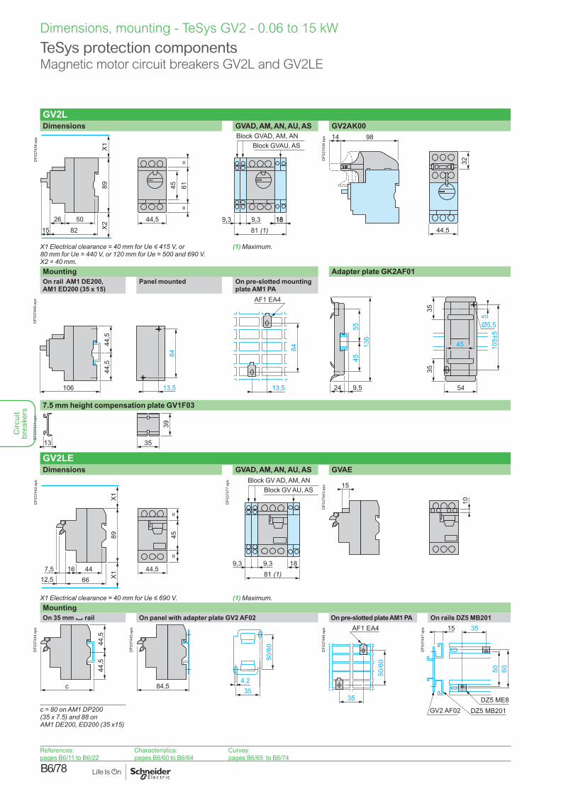
GV2LDimensions GVAD, AM, AN, AU, AS GV2AK00
44,5 9,3 9,381 (1)
1818
89
82
X1
5026
X2
15
6145=
=
Block GVAD, AM, ANBlock GVAU, AS
DF5
3743
8.ep
s 9814
44,5
32DF5
3743
9.ep
s
X1 Electrical clearance = 40 mm for Ue y 415 V, or 80 mm for Ue = 440 V, or 120 mm for Ue = 500 and 690 V.X2 = 40 mm.
(1) Maximum.
Mounting Adapter plate GK2AF01On rail AM1 DE200, AM1 ED200 (35 x 15)
Panel mounted On pre-slotted mounting plate AM1 PA
13,5
84
44,5
44,5
106
45
35
54
105±
5
35
Ø5,5
5
AF1 EA484
13,5 24
5545
135
9,5
DF5
3744
0.ep
s
7.5 mm height compensation plate GV1F03
39
3513
DF5
3744
1.ep
s
GV2LEDimensions GVAD, AM, AN, AU, AS GVAE
44
89
167,56612,5
X1
X1 44,5
45=
=
DF5
3744
2.ep
s
9,3 9,3 1881 (1)
Block GV AD, AM, ANBlock GV AU, AS
DF5
3747
7.ep
s
15
10
DF5
3744
3.ep
s
X1 Electrical clearance = 40 mm for Ue y 690 V. (1) Maximum.MountingOn 35 mm 7 rail On panel with adapter plate GV2 AF02 On pre-slotted plate AM1 PA On rails DZ5 MB201
c
44,5
44,5
DF5
3744
4.ep
s
84,54,235
50/6
0
DF5
3744
5.ep
s AF1 EA4
35
50/6
0
DF5
3744
6.ep
s 15 35
50 60
DZ5 MB201GV2 AF02DZ5 ME8
DF5
3744
7.ep
s
c = 80 on AM1 DP200 (35 x 7.5) and 88 on AM1 DE200, ED200 (35 x15)
TeSys protection componentsMagnetic motor circuit breakers GV2L and GV2LE
References:pages B6/11 to B6/22
Characteristics:pages B6/60 to B6/64
Curves:pages B6/65 to B6/74
Circ
uit
brea
kers
B6/79
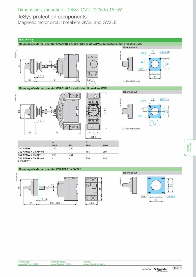
MountingMounting of external operator GV2APN01, GV2APN02 or GV2APN04 for motor circuit breakers GV2L
5,2= =
0,5...4
6
43 6a
60D
B127
415.
eps
Door cut-out
(1) For IP65 only.
48= =
==
48
4Ø3,5 (1)16
16
Ø3,5
Ø22
DB1
2663
4.ep
s
Mounting of external operator GVAPH02 for motor circuit breakers GV2L
0,5...4
6
43 b
60
64,1
173,
4
= =
DB1
2741
4.ep
s Door cut-out
(1) For IP65 only.
48= =
==
48
4Ø3,5 (1)16
16
Ø3,5
Ø22D
B126
634.
eps
a bMini Maxi Mini Maxi
GV2 APNpp 140 250GV2 APNpp + GV APH02 151 250GV2 APNpp + GV APK11 250 434 - -GV2 APNpp + GV APH02 + GV APK11
- - 250 445
Mounting of external operator GV2AP03 for GV2LE
1,5...5
7
53 135…284
65 45=
=
44,5
DB1
2664
9.ep
s Door cut-out
=54
=
==
54DF5
6900
8.ep
s
Dimensions, mounting - TeSys GV2 - 0.06 to 15 kW
TeSys protection componentsMagnetic motor circuit breakers GV2L and GV2LE
References:pages B6/11 to B6/22
Characteristics:pages B6/60 to B6/64
Curves:pages B6/65 to B6/74
Circ
uit
brea
kers
B6/80
Dimensions, mounting - TeSys GV2 - 0.06 to 15 kW
TeSys protection componentsMagnetic motor circuit breakers GV2L and GV2LE
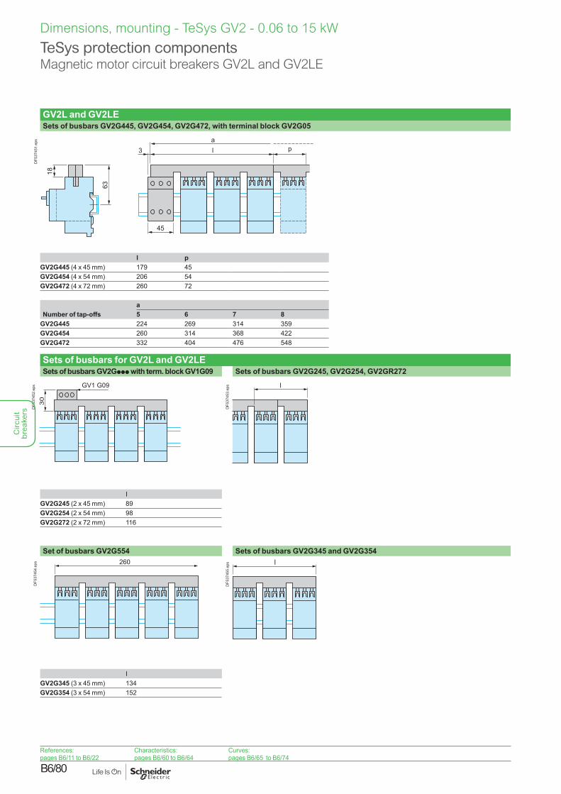
GV2L and GV2LESets of busbars GV2G445, GV2G454, GV2G472, with terminal block GV2G05
63
l3a
18
p
45
DF5
3745
1.ep
s
l pGV2G445 (4 x 45 mm) 179 45GV2G454 (4 x 54 mm) 206 54GV2G472 (4 x 72 mm) 260 72
aNumber of tap-offs 5 6 7 8
GV2G445 224 269 314 359GV2G454 260 314 368 422GV2G472 332 404 476 548
Sets of busbars for GV2L and GV2LE Sets of busbars GV2Gppp with term. block GV1G09 Sets of busbars GV2G245, GV2G254, GV2GR272
GV1 G09
30
DF5
3745
2.ep
s l
DF5
3745
3.ep
s
IGV2G245 (2 x 45 mm) 89GV2G254 (2 x 54 mm) 98GV2G272 (2 x 72 mm) 116
Set of busbars GV2G554 Sets of busbars GV2G345 and GV2G354260
DF5
3745
4.ep
s l
DF5
3745
5.ep
s
IGV2G345 (3 x 45 mm) 134GV2G354 (3 x 54 mm) 152
References:pages B6/11 to B6/22
Characteristics:pages B6/60 to B6/64
Curves:pages B6/65 to B6/74
Circ
uit
brea
kers
B6/81
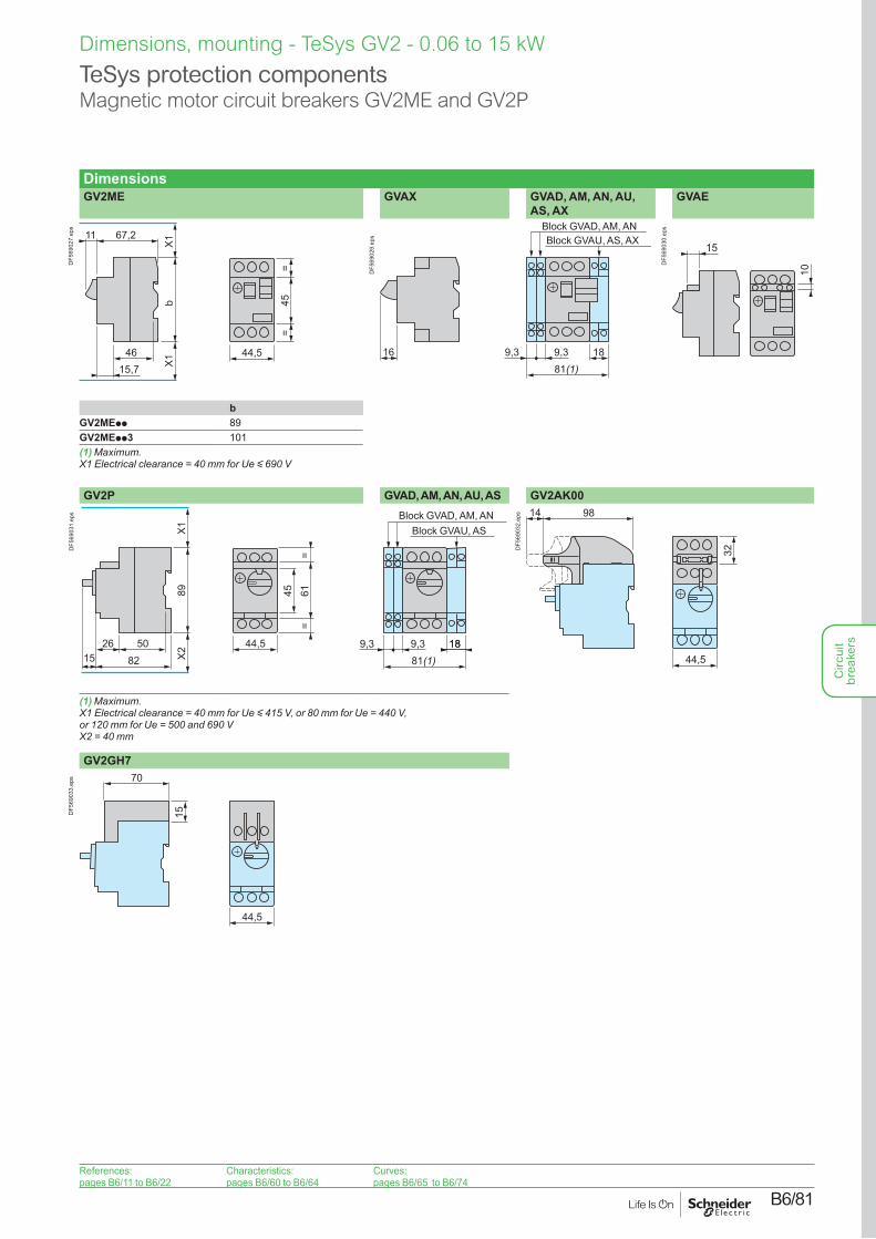
DimensionsGV2ME GVAX GVAD, AM, AN, AU,
AS, AXGVAE
b
67,2
X1
4615,7 X1
11
45=
=
44,5
DF5
6902
7.ep
s
16 9,3 9,381(1)
18
Block GVAD, AM, ANBlock GVAU, AS, AX
DF5
6902
9.ep
s
15
10
DF5
6903
0.ep
s
bGV2MEpp 89GV2MEpp3 101(1) Maximum.X1 Electrical clearance = 40 mm for Ue y 690 V
GV2P GVAD, AM, AN, AU, AS GV2AK00
44,5 9,3 9,381(1)
1818
89
82
X1
5026
X215
6145=
=
Block GVAD, AM, ANBlock GVAU, AS
DF5
6903
1.ep
s 9814
44,5
32DF5
6903
2.ep
s
(1) Maximum.X1 Electrical clearance = 40 mm for Ue y 415 V, or 80 mm for Ue = 440 V, or 120 mm for Ue = 500 and 690 VX2 = 40 mm
GV2GH770
44,5
15DF5
6903
3.ep
s
Dimensions, mounting - TeSys GV2 - 0.06 to 15 kW
TeSys protection componentsMagnetic motor circuit breakers GV2ME and GV2P
References:pages B6/11 to B6/22
Characteristics:pages B6/60 to B6/64
Curves:pages B6/65 to B6/74
Circ
uit
brea
kers
B6/82
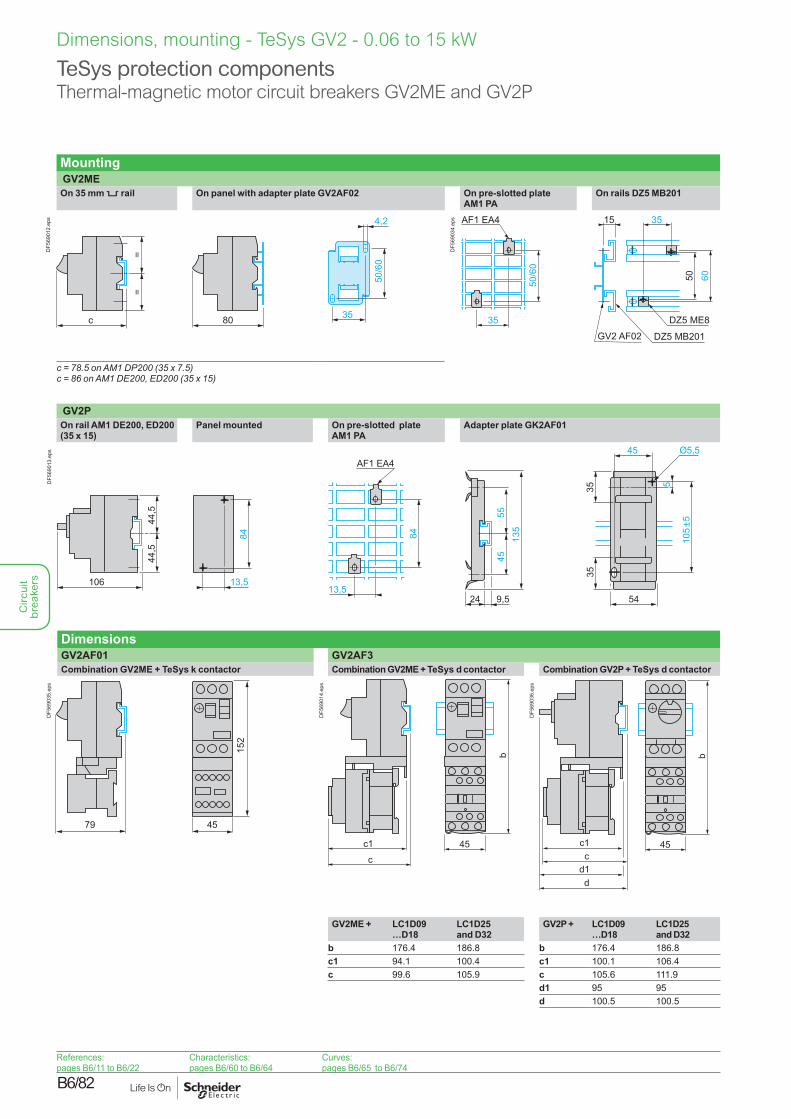
Dimensions, mounting - TeSys GV2 - 0.06 to 15 kW
Mounting GV2MEOn 35 mm 5 rail On panel with adapter plate GV2AF02 On pre-slotted plate
AM1 PAOn rails DZ5 MB201
80c
==
50/6
0
4,2
35
DF5
6901
2.ep
s AF1 EA4
35
50/6
0
35
6050
15
DZ5 MB201GV2 AF02
DZ5 ME8
DF5
6903
4.ep
s
c = 78.5 on AM1 DP200 (35 x 7.5)c = 86 on AM1 DE200, ED200 (35 x 15)
GV2POn rail AM1 DE200, ED200 (35 x 15)
Panel mounted On pre-slotted plate AM1 PA
Adapter plate GK2AF01
13,5
84
44,5
44,5
106
45
3554
105±
5
35 5
AF1 EA4
84
13,524
5545
135
9,5
DF5
6901
3.ep
s
DimensionsGV2AF01 GV2AF3Combination GV2ME + TeSys k contactor Combination GV2ME + TeSys d contactor Combination GV2P + TeSys d contactor
79 45
152
DF5
6903
5.ep
s
c1c
45
b
DF5
6901
4.ep
s
45
b
c1c
dd1
DF5
6903
6.ep
s
GV2ME + LC1D09…D18
LC1D25 and D32
GV2P + LC1D09…D18
LC1D25 and D32
b 176.4 186.8 b 176.4 186.8c1 94.1 100.4 c1 100.1 106.4c 99.6 105.9 c 105.6 111.9
d1 95 95d 100.5 100.5
TeSys protection componentsThermal-magnetic motor circuit breakers GV2ME and GV2P
References:pages B6/11 to B6/22
Characteristics:pages B6/60 to B6/64
Curves:pages B6/65 to B6/74
Circ
uit
brea
kers
B6/83
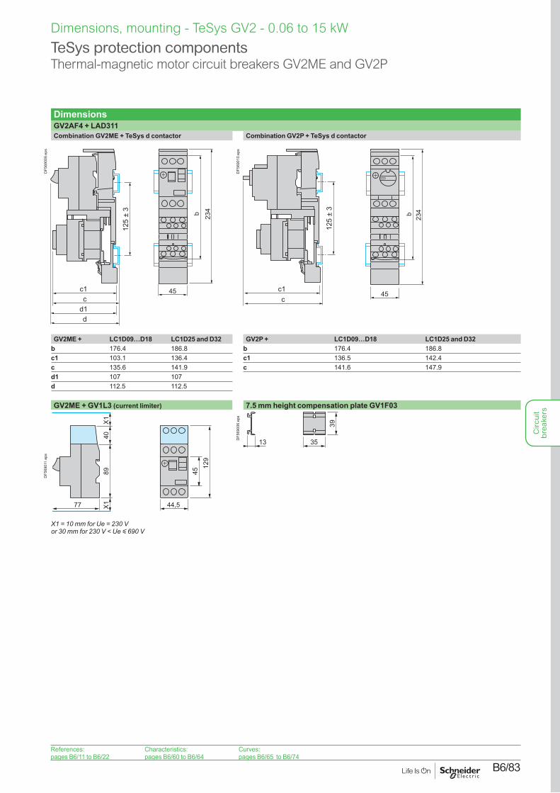
DimensionsGV2AF4 + LAD311Combination GV2ME + TeSys d contactor Combination GV2P + TeSys d contactor
45
b 234
1
c1c
d1d
125
± 3
DF5
6900
9.ep
s
45
b 234
1
c1c
125
± 3
DF5
6901
0.ep
s
GV2ME + LC1D09…D18 LC1D25 and D32 GV2P + LC1D09…D18 LC1D25 and D32b 176.4 186.8 b 176.4 186.8c1 103.1 136.4 c1 136.5 142.4c 135.6 141.9 c 141.6 147.9d1 107 107d 112.5 112.5
GV2ME + GV1L3 (current limiter) 7.5 mm height compensation plate GV1F03
4512
9
44,5
89
77
X1X1
40
DF5
6901
1.ep
s
X1 = 10 mm for Ue = 230 V or 30 mm for 230 V < Ue y 690 V
39
3513DF5
6900
6.ep
s
TeSys protection componentsThermal-magnetic motor circuit breakers GV2ME and GV2P
Dimensions, mounting - TeSys GV2 - 0.06 to 15 kW
References:pages B6/11 to B6/22
Characteristics:pages B6/60 to B6/64
Curves:pages B6/65 to B6/74
Circ
uit
brea
kers
B6/84
TeSys protection componentsThermal-magnetic motor circuit breakers GV2P
Dimensions, mounting - TeSys GV2 - 0.06 to 15 kW
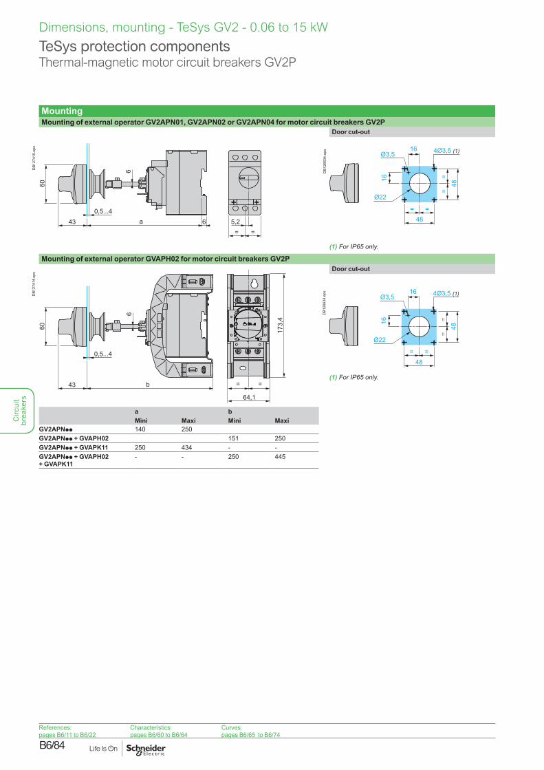
MountingMounting of external operator GV2APN01, GV2APN02 or GV2APN04 for motor circuit breakers GV2P
5,2= =
0,5...4
6
43 6a
60D
B127
415.
eps
Door cut-out
48= =
==
48
4Ø3,5 (1)16
16
Ø3,5
Ø22
DB1
2663
4.ep
s
Mounting of external operator GVAPH02 for motor circuit breakers GV2P
0,5...4
6
43 b
60
64,1
173,
4
= =
DB1
2741
4.ep
s
Door cut-out
(1) For IP65 only.
48= =
==
48
4Ø3,5 (1)16
16
Ø3,5
Ø22
DB1
2663
4.ep
s
a bMini Maxi Mini Maxi
GV2APNpp 140 250GV2APNpp + GVAPH02 151 250GV2APNpp + GVAPK11 250 434 - -GV2APNpp + GVAPH02 + GVAPK11
- - 250 445
(1) For IP65 only.
References:pages B6/11 to B6/22
Characteristics:pages B6/60 to B6/64
Curves:pages B6/65 to B6/74
Circ
uit
brea
kers
B6/85
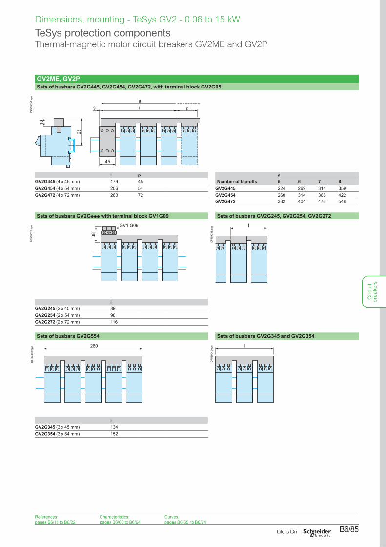
GV2ME, GV2PSets of busbars GV2G445, GV2G454, GV2G472, with terminal block GV2G05
63
l3a
18
p
45
DF5
6903
7.ep
s
l p aGV2G445 (4 x 45 mm) 179 45 Number of tap-offs 5 6 7 8GV2G454 (4 x 54 mm) 206 54 GV2G445 224 269 314 359GV2G472 (4 x 72 mm) 260 72 GV2G454 260 314 368 422
GV2G472 332 404 476 548
Sets of busbars GV2Gppp with terminal block GV1G09 Sets of busbars GV2G245, GV2G254, GV2G272
GV1 G09
38
DF5
6902
8.ep
s l
DF5
6903
8.ep
s
lGV2G245 (2 x 45 mm) 89GV2G254 (2 x 54 mm) 98GV2G272 (2 x 72 mm) 116
Sets of busbars GV2G554 Sets of busbars GV2G345 and GV2G354
260
DF5
6903
9.ep
s l
DF5
6904
0.ep
s
lGV2G345 (3 x 45 mm) 134GV2G354 (3 x 54 mm) 152
TeSys protection componentsThermal-magnetic motor circuit breakers GV2ME and GV2P
Dimensions, mounting - TeSys GV2 - 0.06 to 15 kW
References:pages B6/11 to B6/22
Characteristics:pages B6/60 to B6/64
Curves:pages B6/65 to B6/74
Circ
uit
brea
kers
B6/86
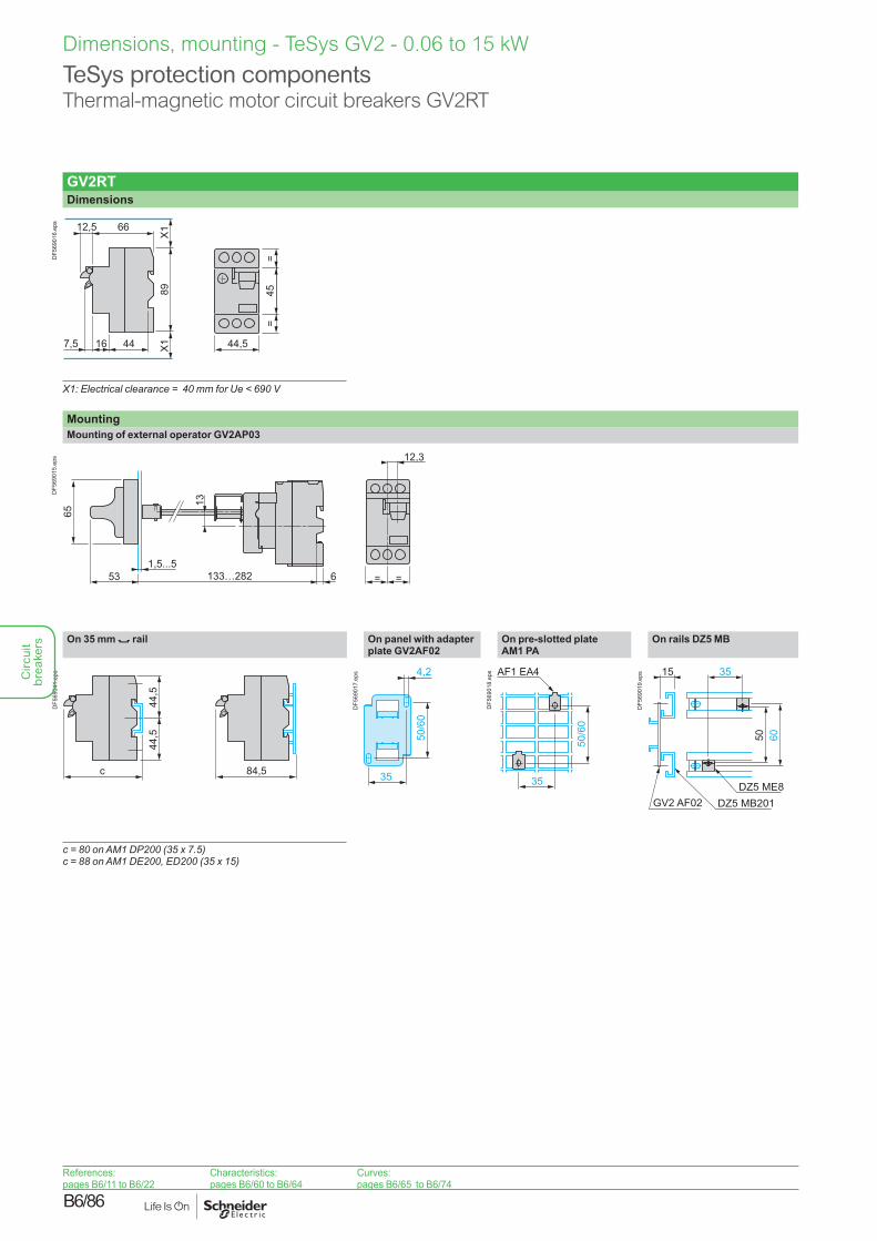
TeSys protection componentsThermal-magnetic motor circuit breakers GV2RT
Dimensions, mounting - TeSys GV2 - 0.06 to 15 kW
GV2RTDimensions
89
66
X1
44167,5 X1
12,5
45=
=
44,5
DF5
6901
6.ep
s
X1: Electrical clearance = 40 mm for Ue < 690 V
MountingMounting of external operator GV2AP03
1,5...5
13
53 133…282
65
6 = =
12,3
DF5
6901
5.ep
s
On 35 mm 7 rail On panel with adapter plate GV2AF02
On pre-slotted plate AM1 PA
On rails DZ5 MB
c
44,5
44,5
84,5
DF5
6904
1.ep
s
50/6
0
4,2
35
DF5
6901
7.ep
s AF1 EA4
35
50/6
0
DF5
6901
8.ep
s 35
6050
15
DZ5 MB201GV2 AF02DZ5 ME8
DF5
6901
9.ep
s
c = 80 on AM1 DP200 (35 x 7.5)c = 88 on AM1 DE200, ED200 (35 x 15)
References:pages B6/11 to B6/22
Characteristics:pages B6/60 to B6/64
Curves:pages B6/65 to B6/74
Circ
uit
brea
kers
B6/87
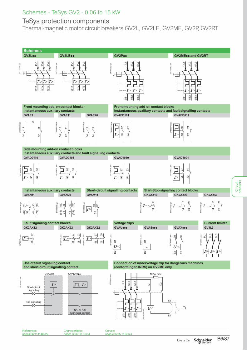
TeSys protection componentsThermal-magnetic motor circuit breakers GV2L, GV2LE, GV2ME, GV2P, GV2RT
Schemes - TeSys GV2 - 0.06 to 15 kW
SchemesGV2Lpp GV2LEpp GV2Ppp GV2MEpp and GV2RT
2/T1
4/T2
6/T3
1/L1
3/L2
5/L3
DF5
1074
4.ep
s
2/T1
4/T2
6/T3
1/L1
3/L2
5/L3
DF5
3745
8.ep
s
2/T1
4/T2
6/T3
1/L1
3/L2
5/L3
DF5
6906
8.ep
s
2/T1
4/T2
6/T3
1/L1
3/L2
5/L3
DF5
6906
7.ep
s
Front mounting add-on contact blocks Instantaneous auxiliary contacts
Front mounting add-on contact blocks Instantaneous auxiliary contacts and fault signalling contacts
GVAE1 GVAE11 GVAE20 GVAED101 GVAED011
1314 12
11
or
DF5
6906
9.ep
s
1314 22
21
DF5
6907
0.ep
s
1314
2324
DF5
6907
1.ep
s
9798
2324
DF5
6907
2.ep
s
9798
2122
DF5
6907
3.ep
s
Side mounting add-on contact blocks Instantaneous auxiliary contacts and fault signalling contactsGVAD0110 GVAD0101 GVAD1010 GVAD1001
535496
95
DF5
6907
4.ep
s
5251
9695
DF5
6907
5.ep
s
9798
5354
DF5
6907
6.ep
s
9798
5152
DF5
6907
7.ep
s
Instantaneous auxiliary contacts Short-circuit signalling contacts Start-Stop signalling contact blocksGVAN11 GVAN20 GVAM11 GK2AX10 GK2AX20 GK2AX50
(62) 32
(61) 31 43 (73)
44 (74)DF5
6907
8.ep
s
(64) 34
(63) 33 43 (73)
44 (74)D
F569
079.
eps
050608
DF5
6908
0.ep
s 1314
DF5
3747
1.ep
s 1314
2324
DF5
3747
2.ep
s
222113
14
DF5
3747
3.ep
s
Fault signaling contact blocks Voltage trips Current limiterGK2AX12 GK2AX22 GK2AX52 GVAUppp GVASppp GVAXppp GV1L3
9798
DF5
3747
4.ep
s 9798
0708
DF5
3747
5.ep
s 9798 06
05
DF5
3747
6.ep
s
D1
D2
DF5
6908
1.ep
s
D1
D2
DF5
1101
2.ep
s
D1
D2
E1 E2
DF5
6908
3.ep
s
1/L1
3/L2
5/L3
DF5
6908
4.ep
s
Use of fault signalling contact and short-circuit signalling contact
Connection of undervoltage trip for dangerous machines (conforming to INRS) on GV2ME only
GVAD10ppGVAM11
Short-circuit signalling
Trip signalling
N/C or N/O Start-Stop contact
DF5
6908
5.ep
s
2/T1
4/T2
6/T3
1/L1
3/L2
5/L3
D1
D2
E2
E1
10Agl max
DF5
6908
6.ep
s
References:pages B6/11 to B6/22
Characteristics:pages B6/60 to B6/64
Curves:pages B6/65 to B6/74
Circ
uit
brea
kers

B6/88
Circ
uit
brea
kers
B6/89
TeSys GV35 to 45 kW
Circ
uit
brea
kers
B6/90
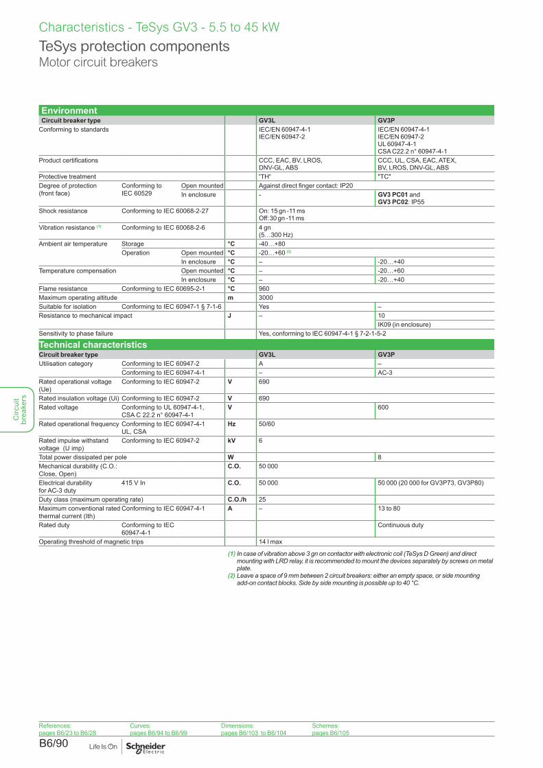
TeSys protection componentsMotor circuit breakers
Characteristics - TeSys GV3 - 5.5 to 45 kW
EnvironmentCircuit breaker type GV3L GV3P
Conforming to standards IEC/EN 60947-4-1 IEC/EN 60947-2
IEC/EN 60947-4-1 IEC/EN 60947-2UL 60947-4-1CSA C22.2 n° 60947-4-1
Product certifications CCC, EAC, BV, LROS, DNV-GL, ABS
CCC, UL, CSA, EAC, ATEX,BV, LROS, DNV-GL, ABS
Protective treatment "TH" "TC"Degree of protection (front face)
Conforming to IEC 60529
Open mounted Against direct finger contact: IP20In enclosure - GV3 PC01 and
GV3 PC02: IP55Shock resistance Conforming to IEC 60068-2-27 On: 15 gn -11 ms
Off: 30 gn -11 msVibration resistance (1) Conforming to IEC 60068-2-6 4 gn
(5…300 Hz)Ambient air temperature Storage °C -40…+80
Operation Open mounted °C -20…+60 (2)
In enclosure °C – -20…+40Temperature compensation Open mounted °C – -20…+60
In enclosure °C – -20…+40Flame resistance Conforming to IEC 60695-2-1 °C 960Maximum operating altitude m 3000Suitable for isolation Conforming to IEC 60947-1 § 7-1-6 Yes –Resistance to mechanical impact J – 10
IK09 (in enclosure)Sensitivity to phase failure Yes, conforming to IEC 60947-4-1 § 7-2-1-5-2
Technical characteristicsCircuit breaker type GV3L GV3PUtilisation category Conforming to IEC 60947-2 A –
Conforming to IEC 60947-4-1 – AC-3Rated operational voltage(Ue)
Conforming to IEC 60947-2 V 690
Rated insulation voltage (Ui) Conforming to IEC 60947-2 V 690Rated voltage Conforming to UL 60947-4-1,
CSA C 22.2 n° 60947-4-1V 600
Rated operational frequency Conforming to IEC 60947-4-1 UL, CSA
Hz 50/60
Rated impulse withstand voltage (U imp)
Conforming to IEC 60947-2 kV 6
Total power dissipated per pole W 8Mechanical durability (C.O.: Close, Open)
C.O. 50 000
Electrical durability for AC-3 duty
415 V In C.O. 50 000 50 000 (20 000 for GV3P73, GV3P80)
Duty class (maximum operating rate) C.O./h 25Maximum conventional rated thermal current (Ith)
Conforming to IEC 60947-4-1 A – 13 to 80
Rated duty Conforming to IEC 60947-4-1
Continuous duty
Operating threshold of magnetic trips 14 l max
(1) In case of vibration above 3 gn on contactor with electronic coil (TeSys D Green) and direct mounting with LRD relay, it is recommended to mount the devices separately by screws on metal plate.
(2) Leave a space of 9 mm between 2 circuit breakers: either an empty space, or side mounting add-on contact blocks. Side by side mounting is possible up to 40 °C.
References:pages B6/23 to B6/28
Curves:pages B6/94 to B6/99
Dimensions:pages B6/103 to B6/104
Schemes:pages B6/105
Circ
uit
brea
kers
B6/91
TeSys protection componentsMotor circuit breakers
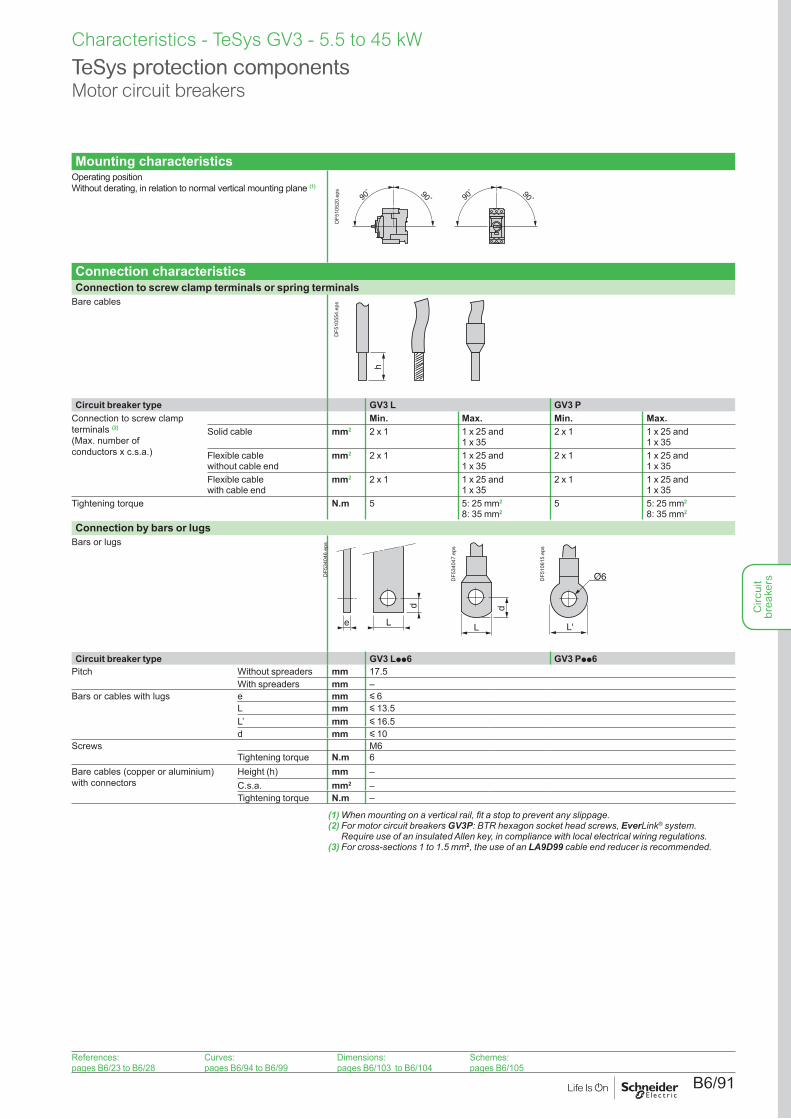
Mounting characteristicsOperating position Without derating, in relation to normal vertical mounting plane (1)
90˚ 90˚90
˚ 90˚
DF5
1052
0.ep
s
Connection characteristicsConnection to screw clamp terminals or spring terminals
Bare cables
h
DF5
1055
4.ep
s
Circuit breaker type GV3 L GV3 PConnection to screw clamp terminals (2) (Max. number of conductors x c.s.a.)
Min. Max. Min. Max.Solid cable mm2 2 x 1 1 x 25 and
1 x 352 x 1 1 x 25 and
1 x 35Flexible cable without cable end
mm2 2 x 1 1 x 25 and 1 x 35
2 x 1 1 x 25 and 1 x 35
Flexible cable with cable end
mm2 2 x 1 1 x 25 and 1 x 35
2 x 1 1 x 25 and 1 x 35
Tightening torque N.m 5 5: 25 mm2
8: 35 mm25 5: 25 mm2
8: 35 mm2
Connection by bars or lugsBars or lugs
e
d
L
DF5
3404
6.ep
s
d
L
DF5
3404
7.ep
s
L'
Ø6DF5
1061
5.ep
s
Circuit breaker type GV3 Lpp6 GV3 Ppp6Pitch Without spreaders mm 17.5
With spreaders mm –Bars or cables with lugs e mm y 6
L mm y 13.5L’ mm y 16.5d mm y 10
Screws M6Tightening torque N.m 6
Bare cables (copper or aluminium) with connectors
Height (h) mm –C.s.a. mm2 –Tightening torque N.m –
(1) When mounting on a vertical rail, fit a stop to prevent any slippage.(2) For motor circuit breakers GV3P: BTR hexagon socket head screws, EverLink® system.
Require use of an insulated Allen key, in compliance with local electrical wiring regulations.(3) For cross-sections 1 to 1.5 mm2, the use of an LA9D99 cable end reducer is recommended.
Characteristics - TeSys GV3 - 5.5 to 45 kW
References:pages B6/23 to B6/28
Curves:pages B6/94 to B6/99
Dimensions:pages B6/103 to B6/104
Schemes:pages B6/105
Circ
uit
brea
kers
B6/92
Characteristics - TeSys GV3 - 5.5 to 45 kW
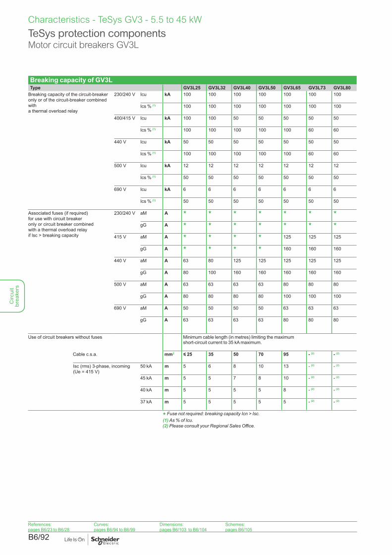
Breaking capacity of GV3LType GV3L25 GV3L32 GV3L40 GV3L50 GV3L65 GV3L73 GV3L80
Breaking capacity of the circuit-breaker only or of the circuit-breaker combined with a thermal overload relay
230/240 V Icu kA 100 100 100 100 100 100 100
Ics % (1) 100 100 100 100 100 100 100
400/415 V Icu kA 100 100 50 50 50 50 50
Ics % (1) 100 100 100 100 100 60 60
440 V Icu kA 50 50 50 50 50 50 50
Ics % (1) 100 100 100 100 100 60 60
500 V Icu kA 12 12 12 12 12 12 12
Ics % (1) 50 50 50 50 50 50 50
690 V Icu kA 6 6 6 6 6 6 6
Ics % (1) 50 50 50 50 50 50 50
Associated fuses (if required) for use with circuit breaker only or circuit breaker combined with a thermal overload relay if lsc > breaking capacity
230/240 V aM A g g g g g g g
gG A g g g g g g g
415 V aM A g g g g 125 125 125
gG A g g g g 160 160 160
440 V aM A 63 80 125 125 125 125 125
gG A 80 100 160 160 160 160 160
500 V aM A 63 63 63 63 80 80 80
gG A 80 80 80 80 100 100 100
690 V aM A 50 50 50 50 63 63 63
gG A 63 63 63 63 80 80 80
Use of circuit breakers without fuses Minimum cable length (in metres) limiting the maximum short-circuit current to 35 kA maximum.
Cable c.s.a. mm2 y 25 35 50 70 95 - (2) - (2)
Isc (rms) 3-phase, incoming (Ue = 415 V)
50 kA m 5 6 8 10 13 - (2) - (2)
45 kA m 5 5 7 8 10 - (2) - (2)
40 kA m 5 5 5 5 8 - (2) - (2)
37 kA m 5 5 5 5 5 - (2) - (2)
g Fuse not required: breaking capacity Icn > Isc.(1) As % of Icu.(2) Please consult your Regional Sales Office.
TeSys protection componentsMotor circuit breakers GV3L
References:pages B6/23 to B6/28
Curves:pages B6/94 to B6/99
Dimensions:pages B6/103 to B6/104
Schemes:pages B6/105
Circ
uit
brea
kers
B6/93
TeSys protection componentsMotor circuit breakers GV3P
Characteristics - TeSys GV3 - 5.5 to 45 kW
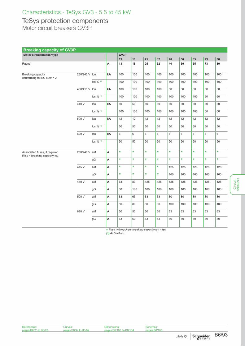
Breaking capacity of GV3PMotor circuit breaker type GV3P
13 18 25 32 40 50 65 73 80Rating A 13 18 25 32 40 50 65 73 80
Breaking capacity conforming to IEC 60947-2
230/240 V Icu kA 100 100 100 100 100 100 100 100 100
Ics % (1) 100 100 100 100 100 100 100 100 100
400/415 V Icu kA 100 100 100 100 50 50 50 50 50
Ics % (1) 100 100 100 100 100 100 100 60 60
440 V Icu kA 50 50 50 50 50 50 50 50 50
Ics % (1) 100 100 100 100 100 100 100 60 60
500 V Icu kA 12 12 12 12 12 12 12 12 12
Ics % (1) 50 50 50 50 50 50 50 50 50
690 V Icu kA 6 6 6 6 6 6 6 6 6
Ics % (1) 50 50 50 50 50 50 50 50 50
Associated fuses, if required if lsc > breaking capacity Icu
230/240 V aM A g g g g g g g g g
gG A g g g g g g g g g
415 V aM A g g g g 125 125 125 125 125
gG A g g g g 160 160 160 160 160
440 V aM A 63 80 125 125 125 125 125 125 125
gG A 80 100 160 160 160 160 160 160 160
500 V aM A 63 63 63 63 80 80 80 80 80
gG A 80 80 80 80 100 100 100 100 100
690 V aM A 50 50 50 50 63 63 63 63 63
gG A 63 63 63 63 80 80 80 80 80
g Fuse not required: breaking capacity Icn > Isc.(1) As % of Icu.
References:pages B6/23 to B6/28
Curves:pages B6/94 to B6/99
Dimensions:pages B6/103 to B6/104
Schemes:pages B6/105
Circ
uit
brea
kers
B6/94
Curves - TeSys GV3 - 5.5 to 45 kW
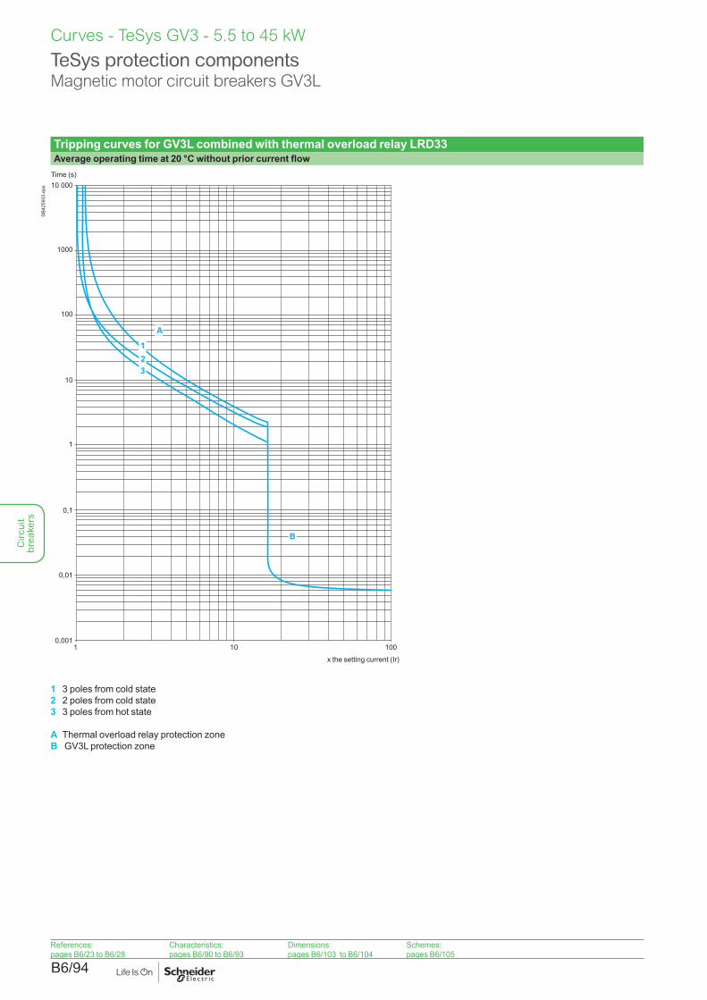
Tripping curves for GV3L combined with thermal overload relay LRD33Average operating time at 20 °C without prior current flow
10
10 000
1
0,1
0,0011 10 100
1000
100
0,01
321
B
A
Time (s)
x the setting current (Ir)
DB4
2593
3.ep
s
1 3 poles from cold state2 2 poles from cold state3 3 poles from hot state
A Thermal overload relay protection zoneB GV3L protection zone
TeSys protection componentsMagnetic motor circuit breakers GV3L
References:pages B6/23 to B6/28
Characteristics:pages B6/90 to B6/93
Dimensions:pages B6/103 to B6/104
Schemes:pages B6/105
Circ
uit
brea
kers
B6/95
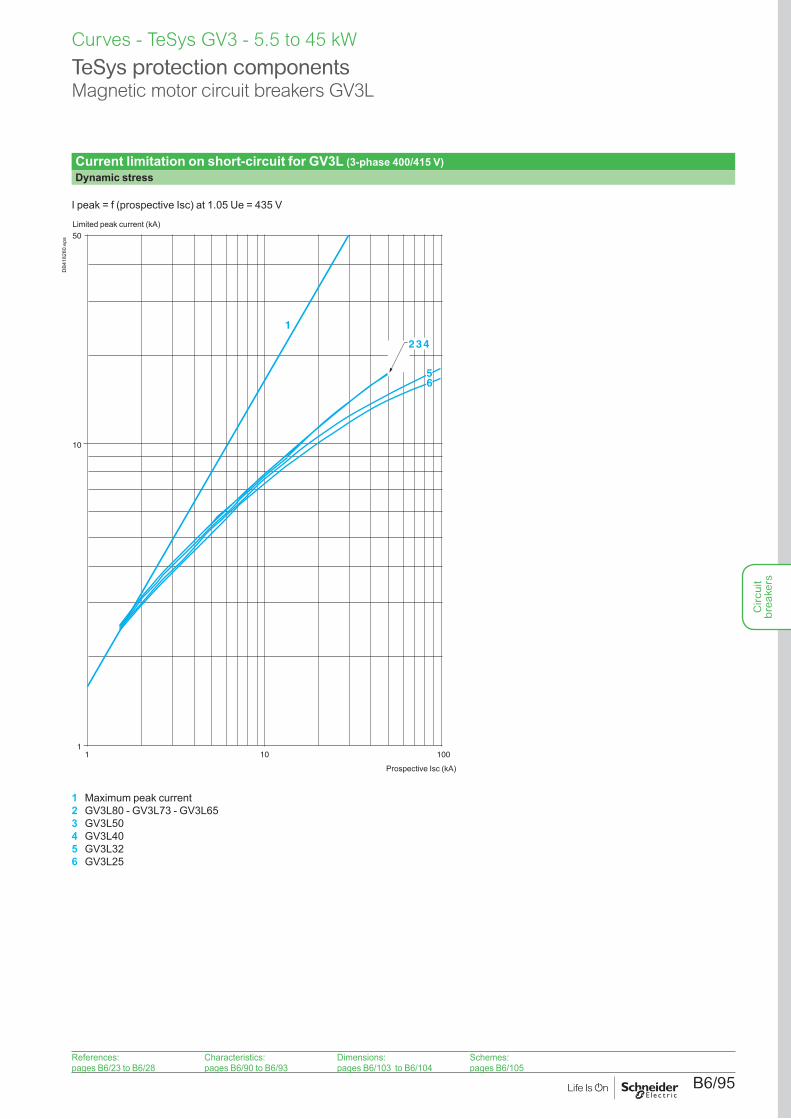
Current limitation on short-circuit for GV3L (3-phase 400/415 V)Dynamic stress
I peak = f (prospective Isc) at 1.05 Ue = 435 V
11 10 100
10
50
1
432
65
Limited peak current (kA)
Prospective Isc (kA)
DB4
1828
0.ep
s
1 Maximum peak current2 GV3L80 - GV3L73 - GV3L653 GV3L504 GV3L405 GV3L326 GV3L25
TeSys protection componentsMagnetic motor circuit breakers GV3L
Curves - TeSys GV3 - 5.5 to 45 kW
References:pages B6/23 to B6/28
Characteristics:pages B6/90 to B6/93
Dimensions:pages B6/103 to B6/104
Schemes:pages B6/105
Circ
uit
brea
kers
B6/96
Curves - TeSys GV3 - 5.5 to 45 kW
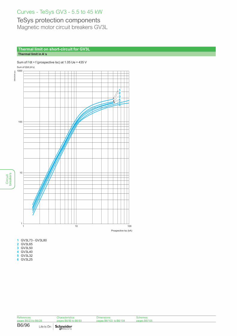
Thermal limit on short-circuit for GV3LThermal limit in A2s
Sum of I2dt = f (prospective Isc) at 1.05 Ue = 435 V
10
11 10 100
100
1000
321
456
Sum of I2dt (A2s)
Prospective Isc (kA)
DB4
2593
6.ep
s
1 GV3L73 - GV3L802 GV3L653 GV3L504 GV3L405 GV3L326 GV3L25
TeSys protection componentsMagnetic motor circuit breakers GV3L
References:pages B6/23 to B6/28
Characteristics:pages B6/90 to B6/93
Dimensions:pages B6/103 to B6/104
Schemes:pages B6/105
Circ
uit
brea
kers
B6/97
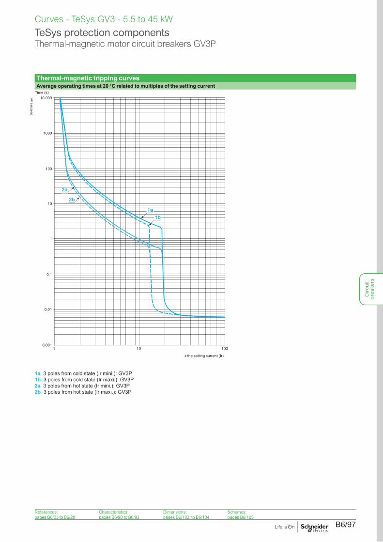
Thermal-magnetic tripping curvesAverage operating times at 20 °C related to multiples of the setting current
0,001
0,1
1
10
100
0,01
1 10 100
1000
10 000
1a1b
2a
2b
Time (s)
x the setting current (Ir)
DB4
2586
3.ep
s
1a 3 poles from cold state (Ir mini.): GV3P1b 3 poles from cold state (Ir maxi.): GV3P2a 3 poles from hot state (Ir mini.): GV3P2b 3 poles from hot state (Ir maxi.): GV3P
TeSys protection componentsThermal-magnetic motor circuit breakers GV3P
Curves - TeSys GV3 - 5.5 to 45 kW
References:pages B6/23 to B6/28
Characteristics:pages B6/90 to B6/93
Dimensions:pages B6/103 to B6/104
Schemes:pages B6/105
Circ
uit
brea
kers
B6/98
Curves - TeSys GV3 - 5.5 to 45 kW
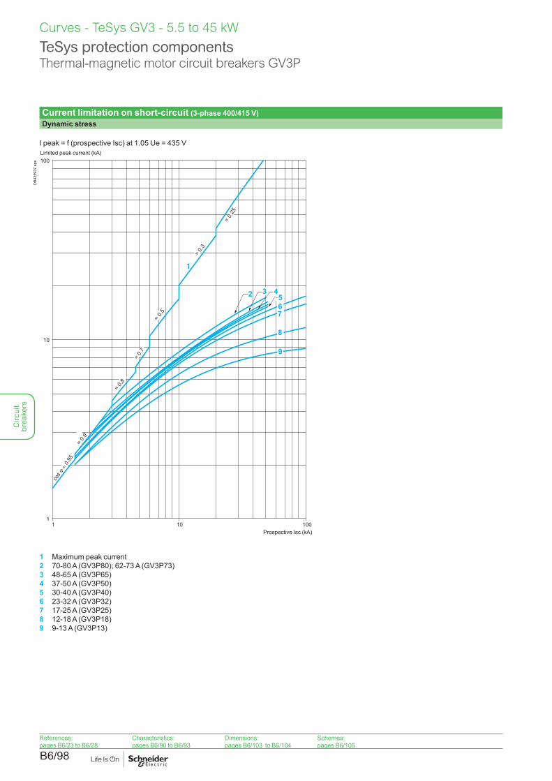
Current limitation on short-circuit (3-phase 400/415 V)Dynamic stress
I peak = f (prospective Isc) at 1.05 Ue = 435 V
1 10 100
100
10
1
76
8
9
= 0.9
= 0.8
= 0.
7
= 0.5
= 0.3
= 0.
25
5
1
3 42
Limited peak current (kA)
Prospective Isc (kA)
DB4
2593
7.ep
s
1 Maximum peak current2 70-80 A (GV3P80); 62-73 A (GV3P73)3 48-65 A (GV3P65)4 37-50 A (GV3P50)5 30-40 A (GV3P40)6 23-32 A (GV3P32)7 17-25 A (GV3P25)8 12-18 A (GV3P18)9 9-13 A (GV3P13)
TeSys protection componentsThermal-magnetic motor circuit breakers GV3P
References:pages B6/23 to B6/28
Characteristics:pages B6/90 to B6/93
Dimensions:pages B6/103 to B6/104
Schemes:pages B6/105
Circ
uit
brea
kers
B6/99
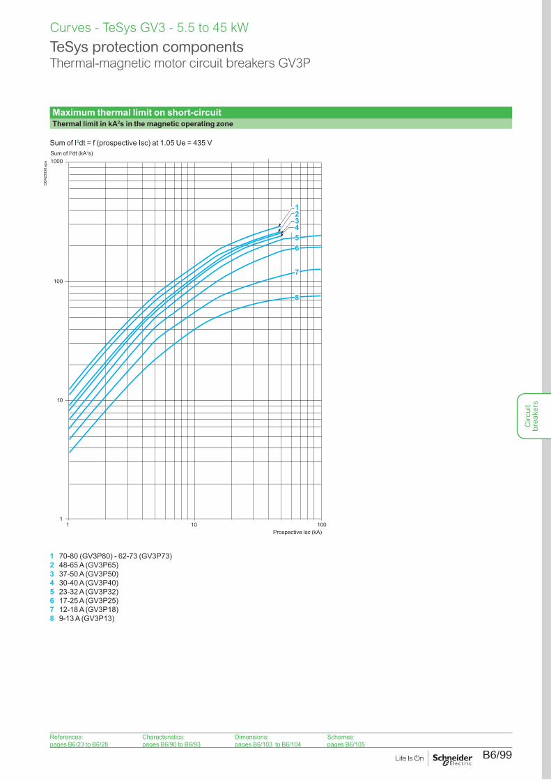
Maximum thermal limit on short-circuitThermal limit in kA2s in the magnetic operating zone
Sum of I2dt = f (prospective Isc) at 1.05 Ue = 435 V
100
1000
10
11 10 100
4321
8
7
65
Sum of I2dt (kA2s)
Prospective Isc (kA)
DB4
2593
8.ep
s
1 70-80 (GV3P80) - 62-73 (GV3P73)2 48-65 A (GV3P65)3 37-50 A (GV3P50)4 30-40 A (GV3P40)5 23-32 A (GV3P32)6 17-25 A (GV3P25)7 12-18 A (GV3P18)8 9-13 A (GV3P13)
TeSys protection componentsThermal-magnetic motor circuit breakers GV3P
Curves - TeSys GV3 - 5.5 to 45 kW
References:pages B6/23 to B6/28
Characteristics:pages B6/90 to B6/93
Dimensions:pages B6/103 to B6/104
Schemes:pages B6/105
Circ
uit
brea
kers
B6/100
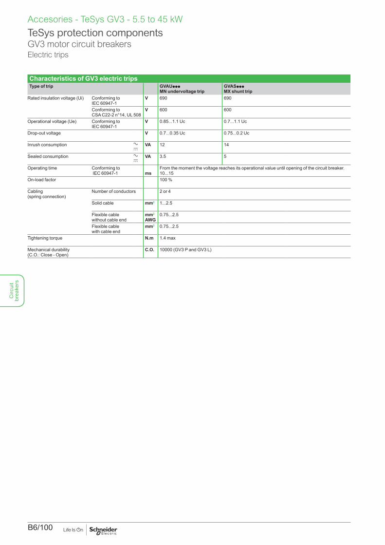
Characteristics of GV3 electric tripsType of trip GVAUppp
MN undervoltage tripGVASppp MX shunt trip
Rated insulation voltage (Ui) Conforming to IEC 60947-1
V 690 690
Conforming to CSA C22-2 n°14, UL 508
V 600 600
Operational voltage (Ue) Conforming to IEC 60947-1
V 0.85...1.1 Uc 0.7...1.1 Uc
Drop-out voltage V 0.7...0.35 Uc 0.75...0.2 Uc
Inrush consumption a c
VA 12 14
Sealed consumption a c
VA 3.5 5
Operating time Conforming to IEC 60947-1 ms
From the moment the voltage reaches its operational value until opening of the circuit breaker. 10...15
On-load factor 100 %
Cabling (spring connection)
Number of conductors 2 or 4
Solid cable mm2 1...2.5
Flexible cable without cable end
mm2
AWG0.75...2.5
Flexible cable with cable end
mm2 0.75...2.5
Tightening torque N.m 1.4 max
Mechanical durability (C.O.: Close - Open)
C.O. 10000 (GV3 P and GV3 L)
TeSys protection componentsGV3 motor circuit breakersElectric trips
Accesories - TeSys GV3 - 5.5 to 45 kWC
ircui
t br
eake
rs
B6/101
Accesories - TeSys GV3 - 5.5 to 45 Kw
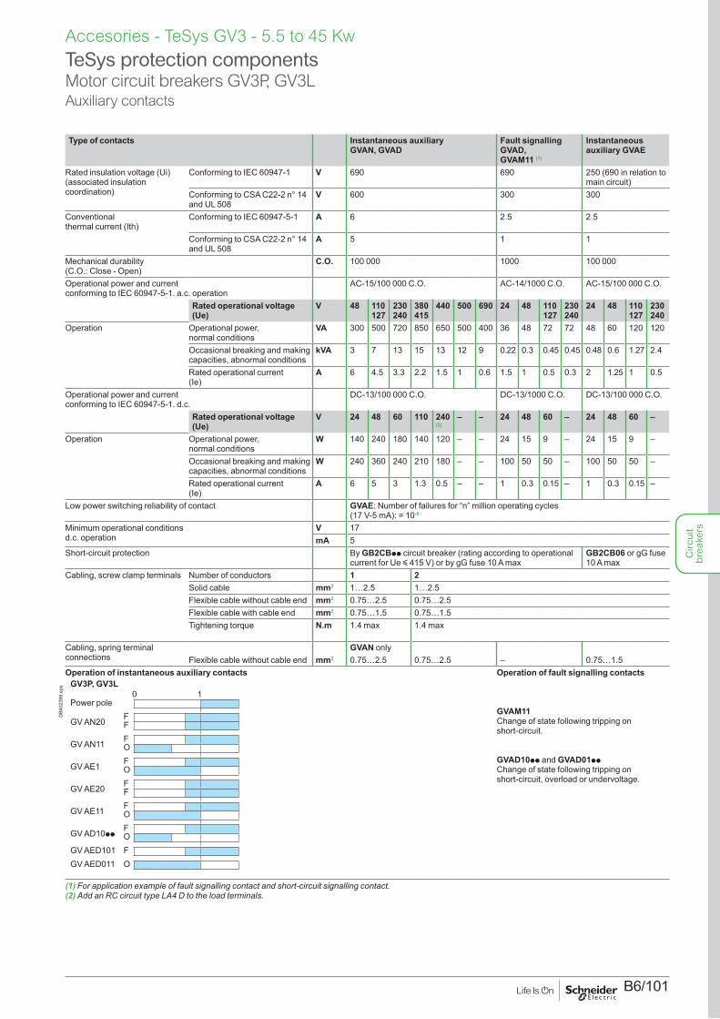
Type of contacts Instantaneous auxiliary GVAN, GVAD
Fault signalling GVAD, GVAM11 (1)
Instantaneous auxiliary GVAE
Rated insulation voltage (Ui) (associated insulation coordination)
Conforming to IEC 60947-1 V 690 690 250 (690 in relation to main circuit)
Conforming to CSA C22-2 n° 14 and UL 508
V 600 300 300
Conventional thermal current (Ith)
Conforming to IEC 60947-5-1 A 6 2.5 2.5
Conforming to CSA C22-2 n° 14 and UL 508
A 5 1 1
Mechanical durability (C.O.: Close - Open)
C.O. 100 000 1000 100 000
Operational power and current conforming to IEC 60947-5-1. a.c. operation
AC-15/100 000 C.O. AC-14/1000 C.O. AC-15/100 000 C.O.
Rated operational voltage (Ue)
V 48 110 127
230 240
380 415
440 500 690 24 48 110 127
230 240
24 48 110 127
230 240
Operation Operational power, normal conditions
VA 300 500 720 850 650 500 400 36 48 72 72 48 60 120 120
Occasional breaking and making capacities, abnormal conditions
kVA 3 7 13 15 13 12 9 0.22 0.3 0.45 0.45 0.48 0.6 1.27 2.4
Rated operational current (Ie)
A 6 4.5 3.3 2.2 1.5 1 0.6 1.5 1 0.5 0.3 2 1.25 1 0.5
Operational power and current conforming to IEC 60947-5-1. d.c.
DC-13/100 000 C.O. DC-13/1000 C.O. DC-13/100 000 C.O.
Rated operational voltage (Ue)
V 24 48 60 110 240(2)
– – 24 48 60 – 24 48 60 –
Operation Operational power, normal conditions
W 140 240 180 140 120 – – 24 15 9 – 24 15 9 –
Occasional breaking and making capacities, abnormal conditions
W 240 360 240 210 180 – – 100 50 50 – 100 50 50 –
Rated operational current (Ie)
A 6 5 3 1.3 0.5 – – 1 0.3 0.15 – 1 0.3 0.15 –
Low power switching reliability of contact GVAE: Number of failures for “n” million operating cycles (17 V-5 mA): = 10-6
Minimum operational conditions d.c. operation
V 17mA 5
Short-circuit protection By GB2CBpp circuit breaker (rating according to operational current for Ue y 415 V) or by gG fuse 10 A max
GB2CB06 or gG fuse 10 A max
Cabling, screw clamp terminals Number of conductors 1 2Solid cable mm2 1…2.5 1…2.5Flexible cable without cable end mm2 0.75…2.5 0.75…2.5Flexible cable with cable end mm2 0.75…1.5 0.75…1.5Tightening torque N.m 1.4 max 1.4 max
Cabling, spring terminal connections
GVAN onlyFlexible cable without cable end mm2 0.75…2.5 0.75…2.5 – 0.75…1.5
Operation of instantaneous auxiliary contactsGV3P, GV3L
0 1Power pole
GV AN20 FF
GV AN11 FO
GV AE1 FO
GV AE20 FF
GV AE11 FO
GV AD10pp FO
GV AED101 FGV AED011 O
GV20 1
Power pole
GV AN20 FF
GV AN11 FO
GV AE1 FO
GV AE20 FF
GV AE11 FO
GV AD10pp FGV AD11pp O
Contact open Contact Close
DB4
0239
9.ep
s
Operation of fault signalling contacts
GVAM11Change of state following tripping on short-circuit.
GVAD10pp and GVAD01ppChange of state following tripping on short-circuit, overload or undervoltage.
(1) For application example of fault signalling contact and short-circuit signalling contact.(2) Add an RC circuit type LA4 D to the load terminals.
TeSys protection componentsMotor circuit breakers GV3P, GV3LAuxiliary contacts
Circ
uit
brea
kers
B6/102
Characteristics - TeSys GV3 - 5.5 to 45 Kw
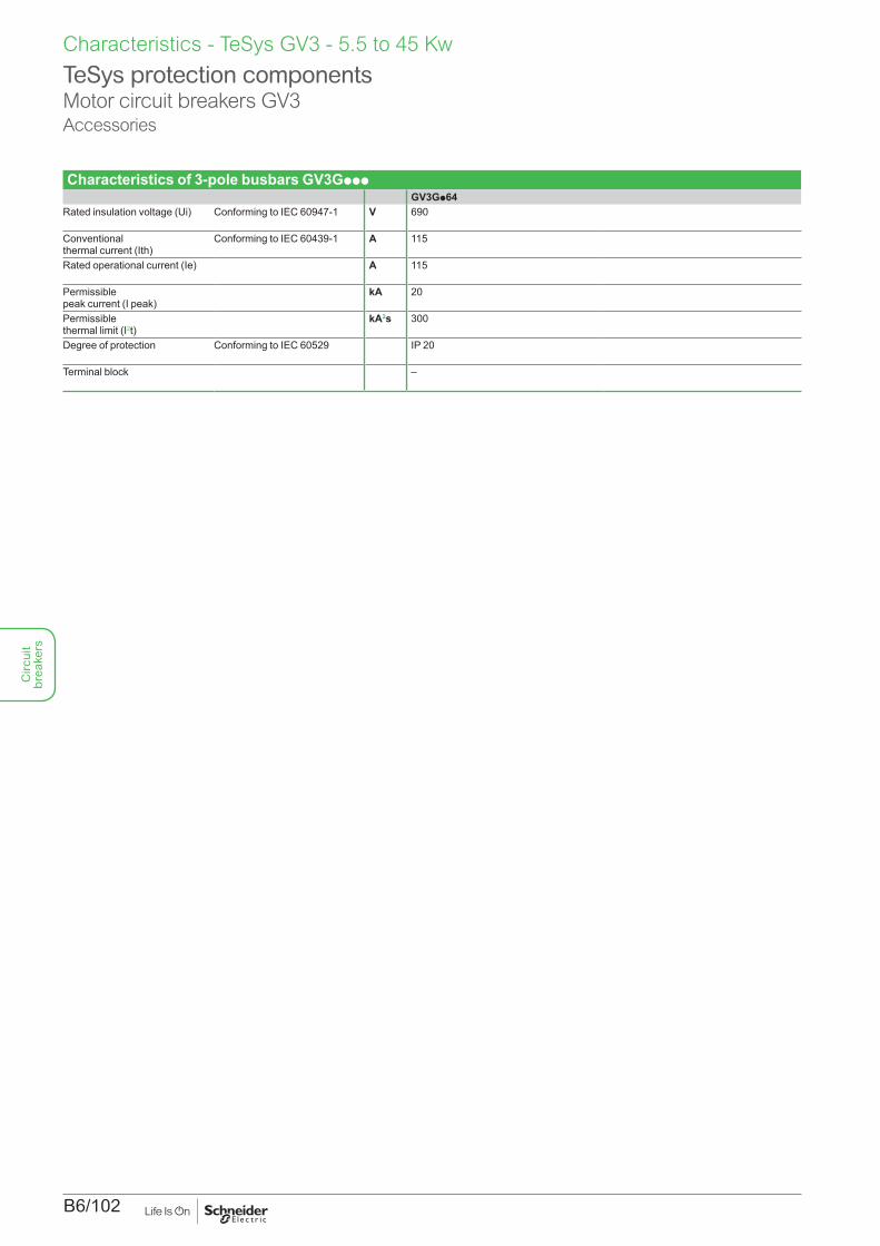
Characteristics of 3-pole busbars GV3GpppGV3Gp64
Rated insulation voltage (Ui) Conforming to IEC 60947-1 V 690
Conventional thermal current (Ith)
Conforming to IEC 60439-1 A 115
Rated operational current (Ie) A 115
Permissible peak current (I peak)
kA 20
Permissible thermal limit (I2t)
kA2s 300
Degree of protection Conforming to IEC 60529 IP 20
Terminal block –
TeSys protection componentsMotor circuit breakers GV3Accessories
Circ
uit
brea
kers
B6/103
Dimensions, mounting - TeSys GV3 - 5.5 to 45 kW
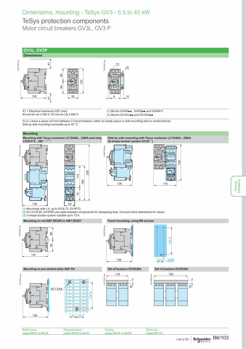
GV3L, GV3PDimensions
136
X1
X1
132
6864
55
DF5
3748
0.ep
s
9 18
(2)(1)
DF5
3748
1.ep
s
X1 = Electrical clearance (ISC max) 40 mm for Ue y 500 V, 50 mm for Ue y 690 V
(1) Blocks GVANpp , GVADpp and GVAM11.(2) Blocks GV3AUpp and GV3ASpp.
Note: Leave a space of 9 mm between 2 circuit breakers: either an empty space or side-mounting add-on contact blocks. Side by side mounting is possible up to 40 °C.
MountingMounting with Tesys contactor LC1D40A…D80A and relay LR3D313…380 (1) (2) (3)
Side by side mounting with Tesys contactor LC1D40A…D80A(S-shape busbar system GV3S (1))
185
299
7011
5
136 55
DF5
6774
4.ep
s
136 11919
5
DF5
6774
5.ep
s
(1) Mountings with c.b. up to GV3L73, GV3P73.(2) For GV3L80, GV3P80 use cable between components for dissipating heat. Consult online datasheets for values(3) S-shape busbar system suitable up to 73 A.
Mounting on rail AM1 DE200 or AM1 ED201 Panel mounting, using M4 screws
144
6864
DF5
3748
2.ep
s
136 3xØ4
137,
5
37,5
DF5
6774
8.ep
s
Mounting on pre-slotted plate AM1 PA Set of busbars GV3G264 Set of busbars GV3G364
136 18,7 18,7
137,
5
AF1 EA4
DF5
3743
5.ep
s 119
16
DF5
1063
7.ep
s 183
16
DF5
1063
8.ep
s
TeSys protection componentsMotor circuit breakers GV3L, GV3 P
References:pages B6/23 to B6/28
Characteristics:pages B6/90 to B6/93
Curves:pages B6/94 to B6/99
Schemes:pages B6/105
Circ
uit
brea
kers
B6/104
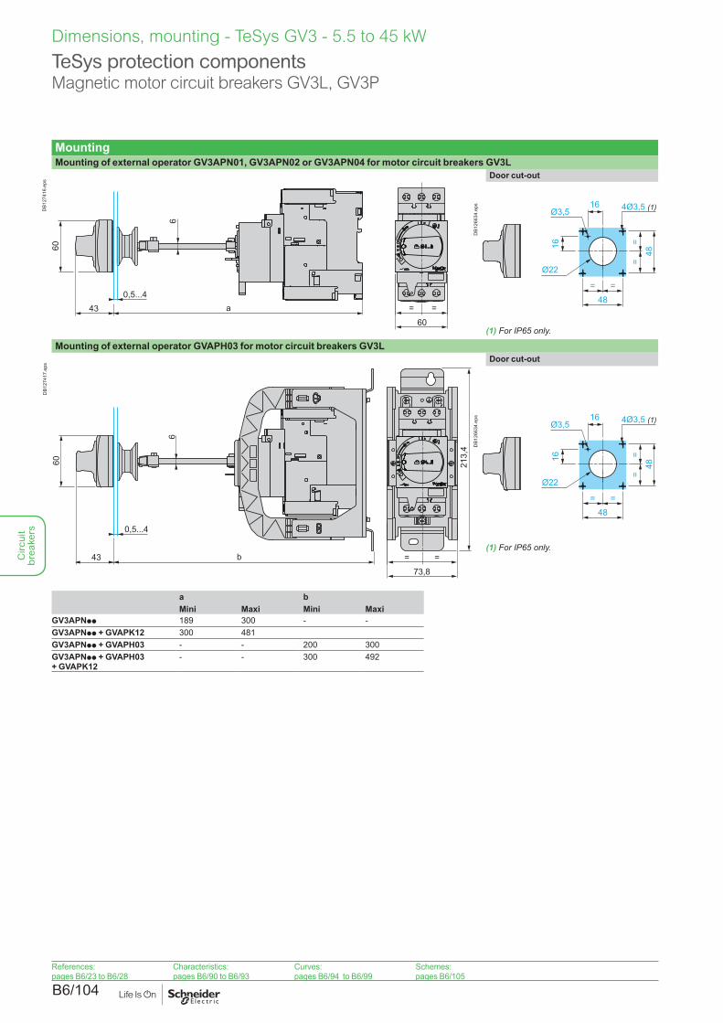
MountingMounting of external operator GV3APN01, GV3APN02 or GV3APN04 for motor circuit breakers GV3L
0,5...443
60
a
60
6
= =
DB1
2741
6.ep
s
Door cut-out
48= =
==
48
4Ø3,5 (1)16
16
Ø3,5
Ø22
DB1
2663
4.ep
s
Mounting of external operator GVAPH03 for motor circuit breakers GV3L
0,5...4
43 b
60
6
213,
4
73,8
= =
DB1
2741
7.ep
s
Door cut-out
48= =
==
48
4Ø3,5 (1)16
16
Ø3,5
Ø22D
B126
634.
eps
a bMini Maxi Mini Maxi
GV3APNpp 189 300 - -GV3APNpp + GVAPK12 300 481GV3APNpp + GVAPH03 - - 200 300GV3APNpp + GVAPH03 + GVAPK12
- - 300 492
(1) For IP65 only.
(1) For IP65 only.
Dimensions, mounting - TeSys GV3 - 5.5 to 45 kW
TeSys protection componentsMagnetic motor circuit breakers GV3L, GV3P
References:pages B6/23 to B6/28
Characteristics:pages B6/90 to B6/93
Curves:pages B6/94 to B6/99
Schemes:pages B6/105
Circ
uit
brea
kers
B6/105
Schemes - TeSys GV3 - 5.5 to 45 kW
TeSys protection componentsMotor circuit breakers GV3L, GV3 P
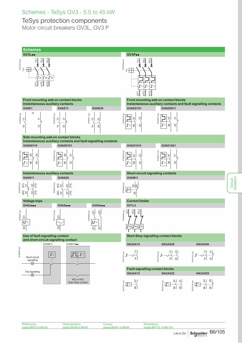
SchemesGV3Lpp GV3Ppp
2/T1
4/T2
6/T3
1/L1
3/L2
5/L3
DF5
1074
4.ep
s
2/T1
4/T2
6/T3
1/L1
3/L2
5/L3
DF5
6906
8.ep
s
Front mounting add-on contact blocks Instantaneous auxiliary contacts
Front mounting add-on contact blocks Instantaneous auxiliary contacts and fault signalling contacts
GVAE1 GVAE11 GVAE20 GVAED101 GVAED011
1314 12
11
or
DF5
6906
9.ep
s
1314 22
21
DF5
6907
0.ep
s
1314
2324
DF5
6907
1.ep
s
9798
2324
DF5
6907
2.ep
s
9798
2122
DF5
6907
3.ep
s
Side mounting add-on contact blocks Instantaneous auxiliary contacts and fault signalling contactsGVAD0110 GVAD0101 GVAD1010 GVAD1001
535496
95
DF5
6907
4.ep
s
5251
9695
DF5
6907
5.ep
s
9798
5354
DF5
6907
6.ep
s
9798
5152
DF5
6907
7.ep
s
Instantaneous auxiliary contacts Short-circuit signalling contactsGVAN11 GVAN20 GVAM11
(62) 32
(61) 31 43 (73)
44 (74)DF5
6907
8.ep
s
(64) 34
(63) 33 43 (73)
44 (74)D
F569
079.
eps
050608
DF5
6908
0.ep
s
Voltage trips Current limiterGVAUppp GVASppp GVAXppp GV1L3
D1
D2
DF5
6908
1.ep
s
D1
D2
DF5
1101
2.ep
s
D1
D2
E1 E2
DF5
6908
3.ep
s
1/L1
3/L2
5/L3
DF5
6908
4.ep
s
Use of fault signalling contact and short-circuit signalling contact
Start-Stop signalling contact blocks
GVAD10ppGVAM11
Short-circuit signalling
Trip signalling
N/C or N/O Start-Stop contact
DF5
6908
5.ep
s
GK2AX10 GK2AX20 GK2AX50
1314
DF5
3747
1.ep
s 1314
2324
DF5
3747
2.ep
s
222113
14
DF5
3747
3.ep
s
Fault signalling contact blocksGK2AX12 GK2AX22 GK2AX52
9798
DF5
3747
4.ep
s 9798
0708
DF5
3747
5.ep
s 9798 06
05
DF5
3747
6.ep
s
References:pages B6/23 to B6/28
Characteristics:pages B6/90 to B6/93
Curves:pages B6/94 to B6/99
Dimensions:pages B6/103 to B6/104
Circ
uit
brea
kers

B6/106
Circ
uit
brea
kers
B6/107
TeSys GV40.25 to 55 kW
Circ
uit
brea
kers
B6/108
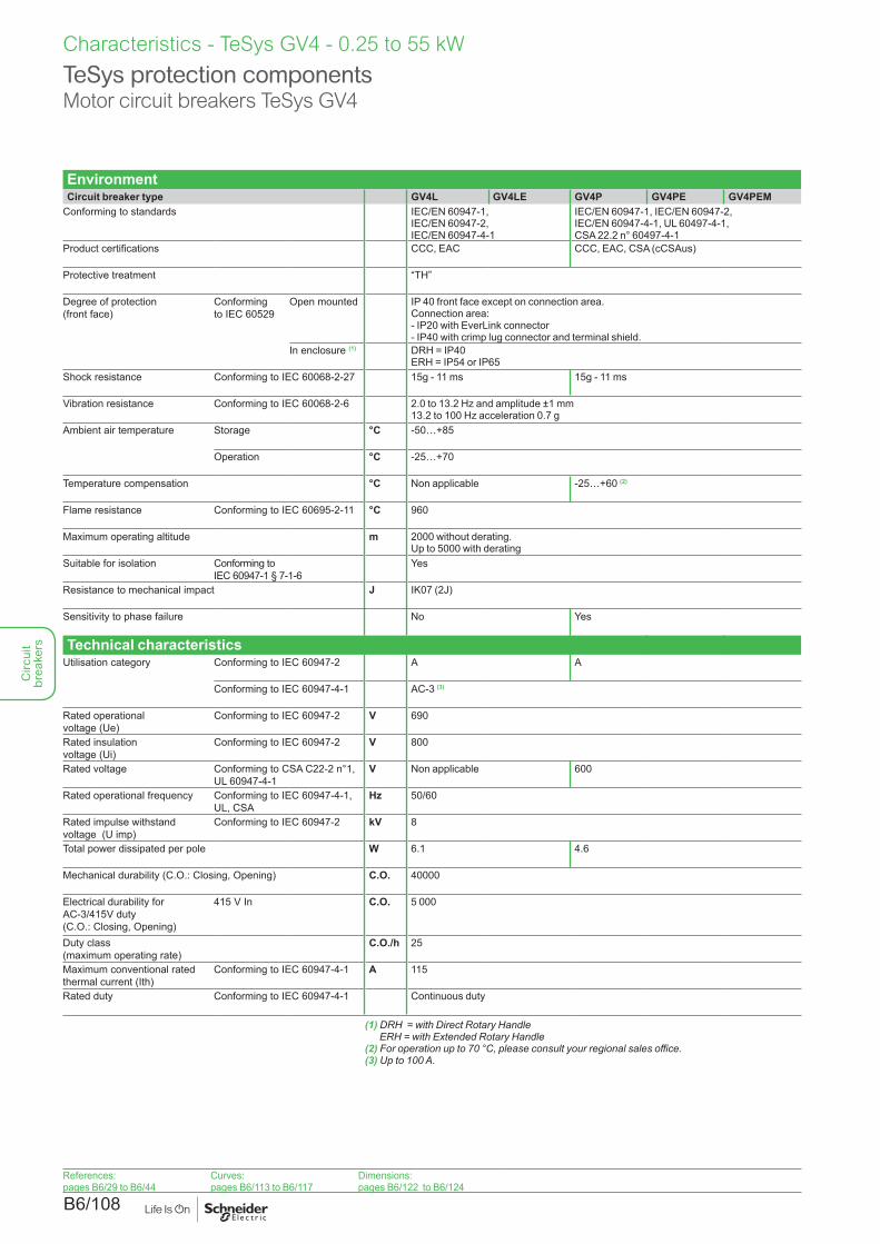
EnvironmentCircuit breaker type GV4L GV4LE GV4P GV4PE GV4PEM
Conforming to standards IEC/EN 60947-1, IEC/EN 60947-2,IEC/EN 60947-4-1
IEC/EN 60947-1, IEC/EN 60947-2, IEC/EN 60947-4-1, UL 60497-4-1, CSA 22.2 n° 60497-4-1
Product certifications CCC, EAC CCC, EAC, CSA (cCSAus)
Protective treatment “TH”
Degree of protection (front face)
Conforming to IEC 60529
Open mounted IP 40 front face except on connection area.Connection area:- IP20 with EverLink connector- IP40 with crimp lug connector and terminal shield.
In enclosure (1) DRH = IP40 ERH = IP54 or IP65
Shock resistance Conforming to IEC 60068-2-27 15g - 11 ms 15g - 11 ms
Vibration resistance Conforming to IEC 60068-2-6 2.0 to 13.2 Hz and amplitude ±1 mm 13.2 to 100 Hz acceleration 0.7 g
Ambient air temperature Storage °C -50…+85
Operation °C -25…+70
Temperature compensation °C Non applicable -25…+60 (2)
Flame resistance Conforming to IEC 60695-2-11 °C 960
Maximum operating altitude m 2000 without derating. Up to 5000 with derating
Suitable for isolation Conforming to IEC 60947-1 § 7-1-6
Yes
Resistance to mechanical impact J IK07 (2J)
Sensitivity to phase failure No Yes
Technical characteristicsUtilisation category Conforming to IEC 60947-2 A A
Conforming to IEC 60947-4-1 AC-3 (3)
Rated operational voltage (Ue)
Conforming to IEC 60947-2 V 690
Rated insulation voltage (Ui)
Conforming to IEC 60947-2 V 800
Rated voltage Conforming to CSA C22-2 n°1, UL 60947-4-1
V Non applicable 600
Rated operational frequency Conforming to IEC 60947-4-1, UL, CSA
Hz 50/60
Rated impulse withstand voltage (U imp)
Conforming to IEC 60947-2 kV 8
Total power dissipated per pole W 6.1 4.6
Mechanical durability (C.O.: Closing, Opening) C.O. 40000
Electrical durability for AC-3/415V duty (C.O.: Closing, Opening)
415 V In C.O. 5 000
Duty class (maximum operating rate)
C.O./h 25
Maximum conventional rated thermal current (Ith)
Conforming to IEC 60947-4-1 A 115
Rated duty Conforming to IEC 60947-4-1 Continuous duty
(1) DRH = with Direct Rotary Handle ERH = with Extended Rotary Handle
(2) For operation up to 70 °C, please consult your regional sales office.(3) Up to 100 A.
TeSys protection componentsMotor circuit breakers TeSys GV4
Characteristics - TeSys GV4 - 0.25 to 55 kW
References:pages B6/29 to B6/44
Curves:pages B6/113 to B6/117
Dimensions:pages B6/122 to B6/124
Circ
uit
brea
kers
B6/109
TeSys protection componentsMotor circuit breakers TeSys GV4
Characteristics - TeSys GV4 - 0.25 to 55 kW
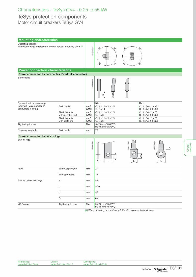
Mounting characteristicsOperating position Without derating, in relation to normal vertical mounting plane (1)
90° 90°90
° 90°
90°90° 90°90°
DB4
2528
3.ep
s
Power connection characteristicsPower connection by bare cables (EverLink connector)
Bare cables
h
DF5
1055
4.ep
s
Connection to screw clamp terminals (Max. number of conductors x c.s.a.)
Min. Max.Solid cable mm2
AWGCu 1 x 1.5 + 1 x 2.5 Cu 2 x 14
Cu 1 x 70 + 1 x 95 Cu 1 x 2/0 + 1 x 3/0
Flexible cable without cable end
mm2
AWGCu 1 x 1.5 + 1 x 2.5 Cu 2 x 6
Cu 1 x 50 + 1 x 70 Cu 1 x 1/0 + 1 x 2/0
Flexible cable with cable end
mm2
AWGCu 1 x 1.5 + 1 x 2.5 Cu 2 x 6
Cu 1 x 50 + 1 x 70Cu 1 x 1/0 + 1 x 2/0
Tightening torque N.m 5 y 10 mm2 / 8 AWG 9 u 16 mm2 / 6 AWG
Stripping length (h) Solid cable mm 20
Power connection by bars or lugsBars or lugs
e
d
L
DF5
3404
6.ep
s
d
L
DF5
3404
7R.e
ps
D
L
DB4
2527
8.ep
s
Pitch Without spreaders mm 27
With spreaders mm 35
Bars or cables with lugs e mm y 8
L mm y 20
d mm y 7
D mm 6.4
M6 Screws Tightening torque N.m 5 y 10 mm2 / 8 AWG 9 u 16 mm2 / 6 AWG
(1) When mounting on a vertical rail, fit a stop to prevent any slippage.
References:pages B6/29 to B6/44
Curves:pages B6/113 to B6/117
Dimensions:pages B6/122 to B6/124
Circ
uit
brea
kers
B6/110
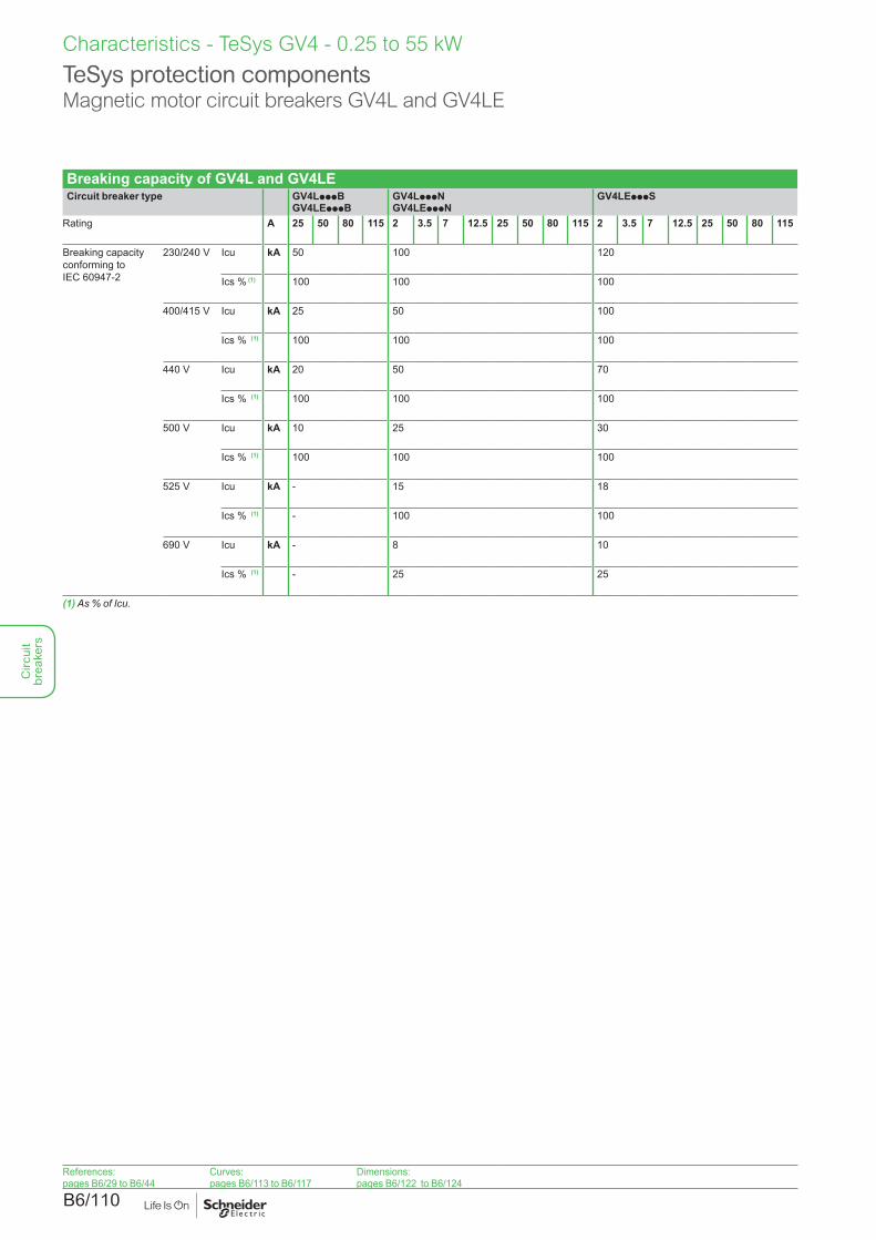
Breaking capacity of GV4L and GV4LECircuit breaker type GV4LpppB
GV4LEpppBGV4LpppN GV4LEpppN
GV4LEpppS
Rating A 25 50 80 115 2 3.5 7 12.5 25 50 80 115 2 3.5 7 12.5 25 50 80 115
Breaking capacity conforming to IEC 60947-2
230/240 V Icu kA 50 100 120
Ics % (1) 100 100 100
400/415 V Icu kA 25 50 100
Ics % (1) 100 100 100
440 V Icu kA 20 50 70
Ics % (1) 100 100 100
500 V Icu kA 10 25 30
Ics % (1) 100 100 100
525 V Icu kA - 15 18
Ics % (1) - 100 100
690 V Icu kA - 8 10
Ics % (1) - 25 25
(1) As % of Icu.
TeSys protection componentsMagnetic motor circuit breakers GV4L and GV4LE
Characteristics - TeSys GV4 - 0.25 to 55 kW
References:pages B6/29 to B6/44
Curves:pages B6/113 to B6/117
Dimensions:pages B6/122 to B6/124
Circ
uit
brea
kers
B6/111
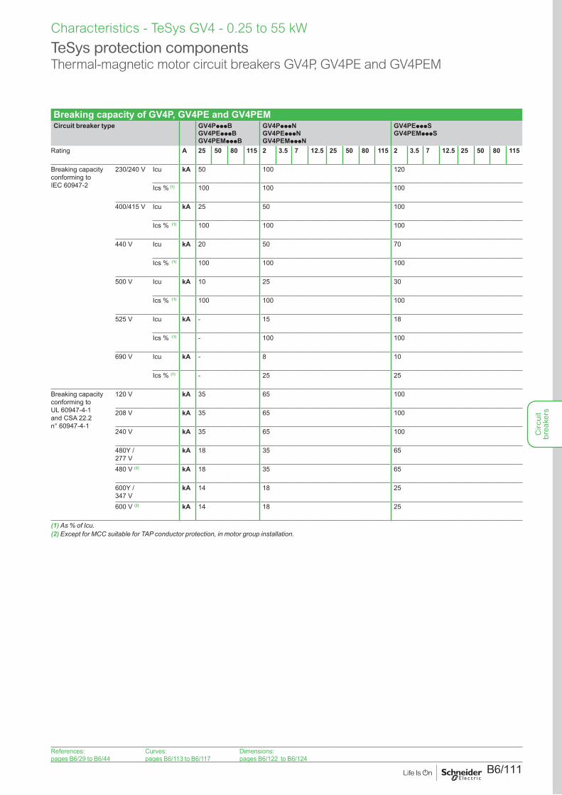
Breaking capacity of GV4P, GV4PE and GV4PEMCircuit breaker type GV4PpppB
GV4PEpppB GV4PEMpppB
GV4PpppN GV4PEpppN GV4PEMpppN
GV4PEpppS GV4PEMpppS
Rating A 25 50 80 115 2 3.5 7 12.5 25 50 80 115 2 3.5 7 12.5 25 50 80 115
Breaking capacity conforming to IEC 60947-2
230/240 V Icu kA 50 100 120
Ics % (1) 100 100 100
400/415 V Icu kA 25 50 100
Ics % (1) 100 100 100
440 V Icu kA 20 50 70
Ics % (1) 100 100 100
500 V Icu kA 10 25 30
Ics % (1) 100 100 100
525 V Icu kA - 15 18
Ics % (1) - 100 100
690 V Icu kA - 8 10
Ics % (1) - 25 25
Breaking capacity conforming to UL 60947-4-1 and CSA 22.2 n° 60947-4-1
120 V kA 35 65 100
208 V kA 35 65 100
240 V kA 35 65 100
480Y / 277 V
kA 18 35 65
480 V (2) kA 18 35 65
600Y / 347 V
kA 14 18 25
600 V (2) kA 14 18 25
(1) As % of Icu.(2) Except for MCC suitable for TAP conductor protection, in motor group installation.
TeSys protection componentsThermal-magnetic motor circuit breakers GV4P, GV4PE and GV4PEM
Characteristics - TeSys GV4 - 0.25 to 55 kW
References:pages B6/29 to B6/44
Curves:pages B6/113 to B6/117
Dimensions:pages B6/122 to B6/124
Circ
uit
brea
kers
B6/112
Curves - TeSys GV4 - 0.25 to 55 kW
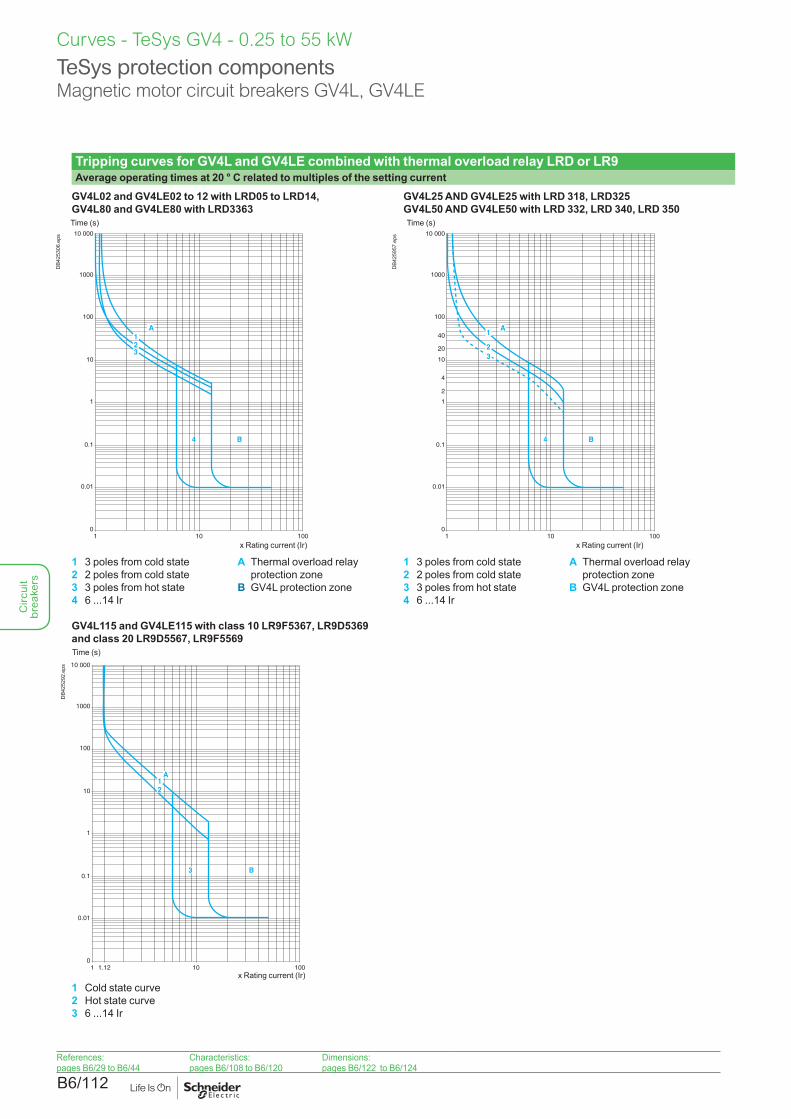
Tripping curves for GV4L and GV4LE combined with thermal overload relay LRD or LR9Average operating times at 20 ° C related to multiples of the setting current
GV4L02 and GV4LE02 to 12 with LRD05 to LRD14, GV4L80 and GV4LE80 with LRD3363
GV4L25 AND GV4LE25 with LRD 318, LRD325 GV4L50 AND GV4LE50 with LRD 332, LRD 340, LRD 350
A1
A
B
23
0
0.01
0.1
1
10
100
10 000
1000
1 10 100
4
Time (s)
x Rating current (Ir)
DB4
2530
6.ep
s
A1
A
B
23
0
0.01
0.1
1
2
4
20
40
10
100
10 000
1000
1 10 100
4
Time (s)
x Rating current (Ir)
DB4
2595
7.ep
s
1 3 poles from cold state2 2 poles from cold state3 3 poles from hot state4 6 ...14 Ir
A Thermal overload relay protection zone
B GV4L protection zone
1 3 poles from cold state2 2 poles from cold state3 3 poles from hot state4 6 ...14 Ir
A Thermal overload relay protection zone
B GV4L protection zone
GV4L115 and GV4LE115 with class 10 LR9F5367, LR9D5369 and class 20 LR9D5567, LR9F5569
0
0.01
0.1
1
10
100
10 000
1000
1 101.12 100
2
3 B
1A
Time (s)
x Rating current (Ir)
DB4
2529
2.ep
s
1 Cold state curve2 Hot state curve3 6 ...14 Ir
TeSys protection componentsMagnetic motor circuit breakers GV4L, GV4LE
References:pages B6/29 to B6/44
Characteristics:pages B6/108 to B6/120
Dimensions:pages B6/122 to B6/124
Circ
uit
brea
kers
B6/113
Curves - TeSys GV4 - 0.25 to 55 kW
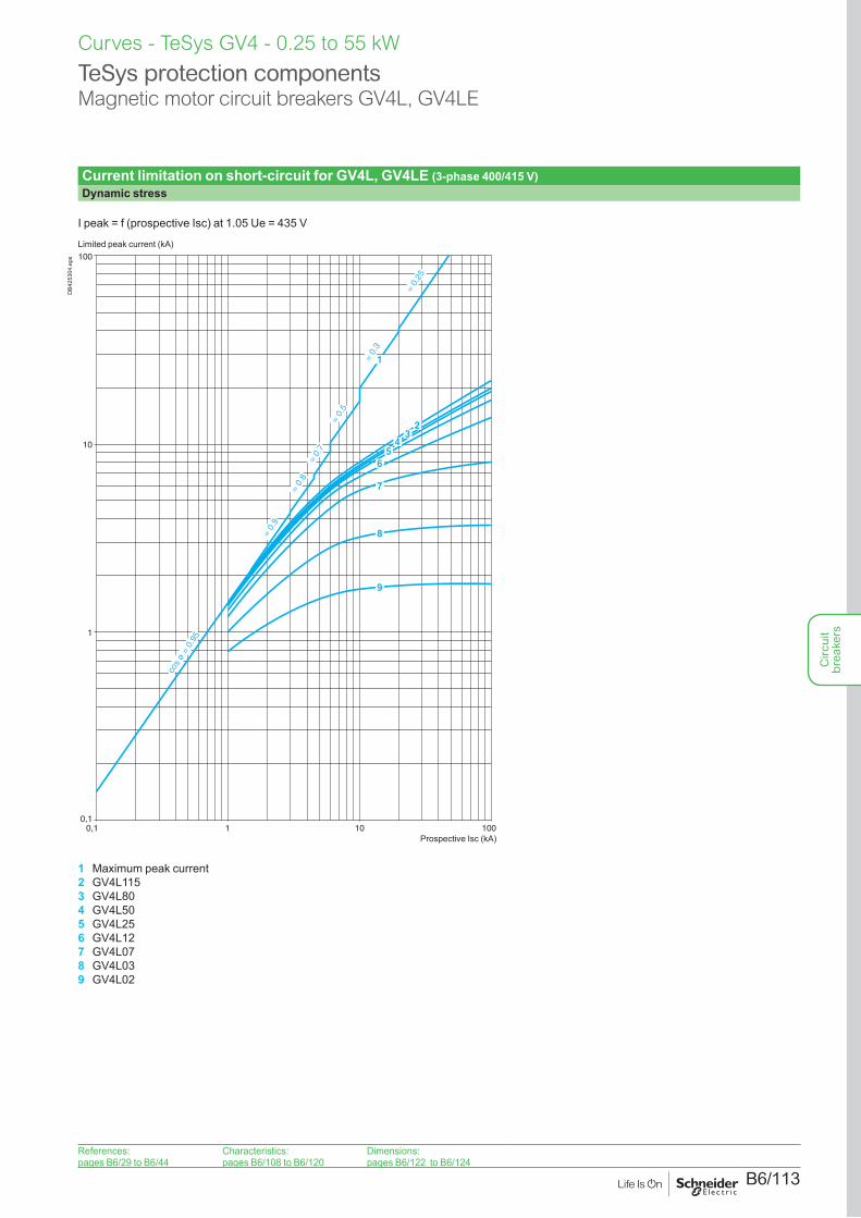
Current limitation on short-circuit for GV4L, GV4LE (3-phase 400/415 V)Dynamic stress
I peak = f (prospective Isc) at 1.05 Ue = 435 V
cos
ø =
0.95
= 0.
9
= 0.
8=
0.7
= 0.
5
= 0.
25
= 0.
3
1
23
45
6
7
8
9
0,1
1
10
100
0,1 1 10 100
Limited peak current (kA)
Prospective Isc (kA)
DB4
2530
4.ep
s
1 Maximum peak current2 GV4L1153 GV4L804 GV4L505 GV4L256 GV4L127 GV4L078 GV4L039 GV4L02
TeSys protection componentsMagnetic motor circuit breakers GV4L, GV4LE
References:pages B6/29 to B6/44
Characteristics:pages B6/108 to B6/120
Dimensions:pages B6/122 to B6/124
Circ
uit
brea
kers
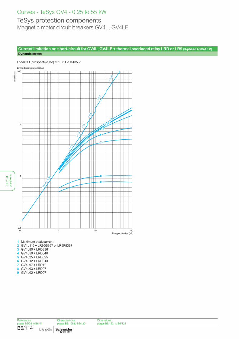
B6/114
Current limitation on short-circuit for GV4L, GV4LE + thermal overlaoad relay LRD or LR9 (3-phase 400/415 V)Dynamic stress
I peak = f (prospective Isc) at 1.05 Ue = 435 V
cos
ø =
0.95
= 0.
9
= 0.
8=
0.7
= 0.
5
= 0.
25
= 0.
31
0,1
1
10
100
0,1 1 10 100
23
4
5
6
7
8
9
Limited peak current (kA)
Prospective Isc (kA)
DB4
2530
5.ep
s
1 Maximum peak current2 GV4L115 + LR9D5367 or LR9F53673 GV4L80 + LRD33614 GV4L50 + LRD3405 GV4L25 + LRD3256 GV4L12 + LRD3137 GV4L07 + LRD128 GV4L03 + LRD079 GV4L02 + LRD07
TeSys protection componentsMagnetic motor circuit breakers GV4L, GV4LE
Curves - TeSys GV4 - 0.25 to 55 kW
References:pages B6/29 to B6/44
Characteristics:pages B6/108 to B6/120
Dimensions:pages B6/122 to B6/124
Circ
uit
brea
kers
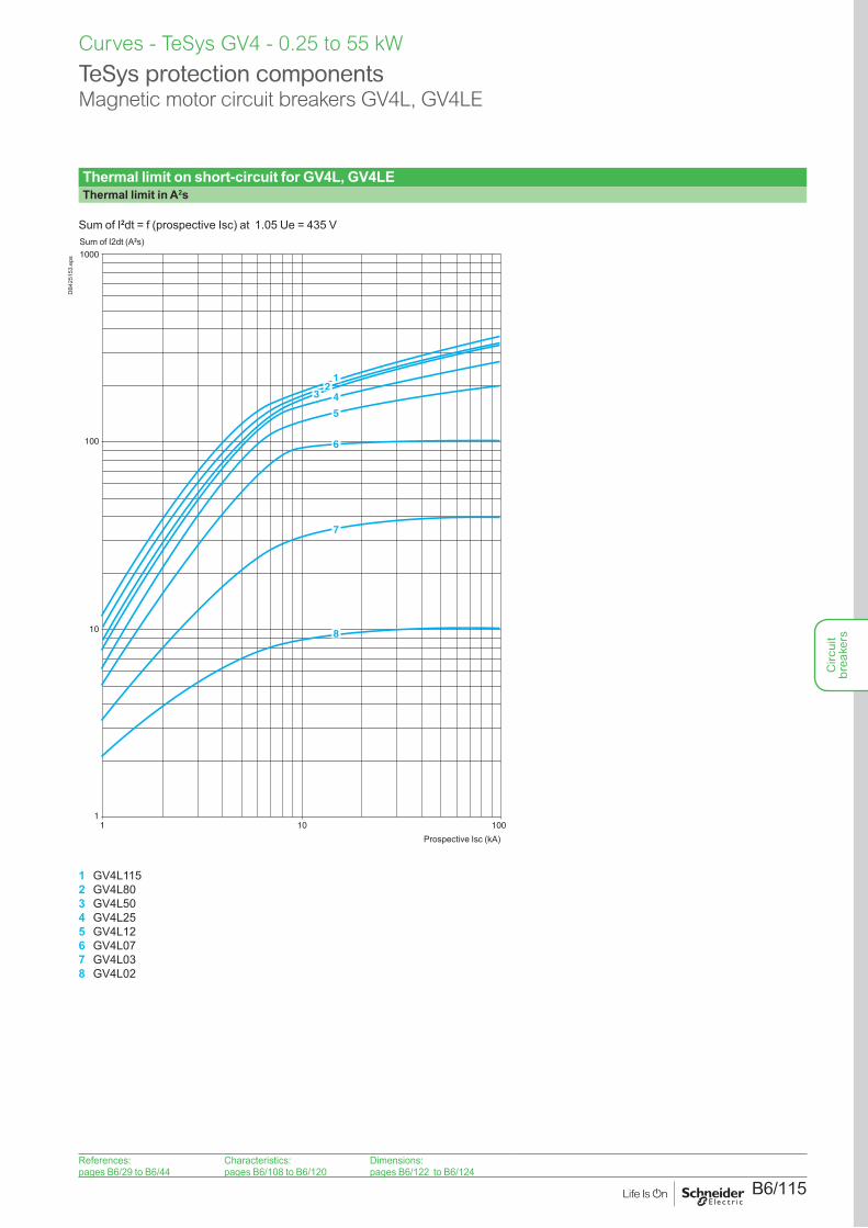
B6/115
Thermal limit on short-circuit for GV4L, GV4LEThermal limit in A2s
Sum of I2dt = f (prospective Isc) at 1.05 Ue = 435 V
1
10
100
1000
1 10 100
12
3 4
5
6
7
8
Sum of I2dt (A2s)
Prospective Isc (kA)
DB4
2515
3.ep
s
1 GV4L1152 GV4L803 GV4L504 GV4L255 GV4L126 GV4L077 GV4L038 GV4L02
TeSys protection componentsMagnetic motor circuit breakers GV4L, GV4LE
Curves - TeSys GV4 - 0.25 to 55 kW
References:pages B6/29 to B6/44
Characteristics:pages B6/108 to B6/120
Dimensions:pages B6/122 to B6/124
Circ
uit
brea
kers

B6/116
Thermal limit on short-circuit for GV4L, GV4LE + thermal overlaoad relay LRD or LR9Thermal limit in kA in the magnetic operating zone
Sum of I2dt = f (prospective Isc) at 1.05 Ue = 435 V
0,1
1
10
100
1000
1 10 100
123 4
5
6
7
8
Sum of I2dt (A2s)
Prospective Isc (kA)
DB4
2515
4.ep
s
1 GV4L115 + LR9D5367 or LR9F53672 GV4L80 + LRD33613 GV4L50 + LRD3404 GV4L25 + LRD3255 GV4L12 + LRD3136 GV4L07+ LRD127 GV4L03+ LRD078 GV4L02 + LRD07
TeSys protection componentsMagnetic motor circuit breakers GV4L, GV4LE
Curves - TeSys GV4 - 0.25 to 55 kW
References:pages B6/29 to B6/44
Characteristics:pages B6/108 to B6/120
Dimensions:pages B6/122 to B6/124
Circ
uit
brea
kers
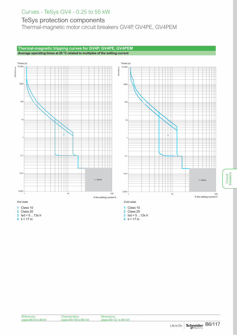
B6/117
TeSys protection componentsThermal-magnetic motor circuit breakers GV4P, GV4PE, GV4PEM
Curves - TeSys GV4 - 0.25 to 55 kW
Thermal-magnetic tripping curves for GV4P, GV4PE, GV4PEMAverage operating times at 20 °C related to multiples of the setting current
0.001
0.01
0.1
1
10
100
10 000
1000
1 10 100
t < 20ms
2
1
3
4
Times (s)
X the setting current Ir
DB4
2593
0.ep
s
0.001
0.01
0.1
1
10
100
10 000
1000
1 10 100
3
t < 20ms
4
2
1
Times (s)
X the setting current Ir
DB4
2595
8.ai
Hot state Cold state
1 Class 102 Class 203 Isd = 5 ...13x Ir4 Ii = 17 In
1 Class 102 Class 203 Isd = 5 ...13x Ir4 Ii = 17 In
References:pages B6/29 to B6/44
Characteristics:pages B6/108 to B6/120
Dimensions:pages B6/122 to B6/124
Circ
uit
brea
kers
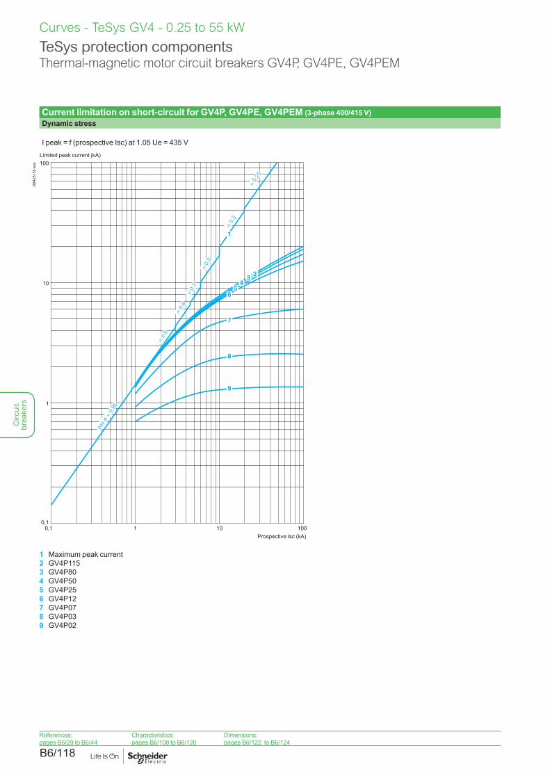
B6/118
Current limitation on short-circuit for GV4P, GV4PE, GV4PEM (3-phase 400/415 V)Dynamic stress
I peak = f (prospective Isc) at 1.05 Ue = 435 V
0,1
1
10
100
0,1 1
cos
ø =
0.95
10 100
= 0.
9
= 0.
8=
0.7
= 0.
5
= 0.
3
= 0.
25
1
234
56
7
8
9
Limited peak current (kA)
Prospective Isc (kA)
DB4
2515
5.ep
s
1 Maximum peak current2 GV4P1153 GV4P804 GV4P505 GV4P256 GV4P127 GV4P078 GV4P039 GV4P02
TeSys protection componentsThermal-magnetic motor circuit breakers GV4P, GV4PE, GV4PEM
Curves - TeSys GV4 - 0.25 to 55 kW
References:pages B6/29 to B6/44
Characteristics:pages B6/108 to B6/120
Dimensions:pages B6/122 to B6/124
Circ
uit
brea
kers
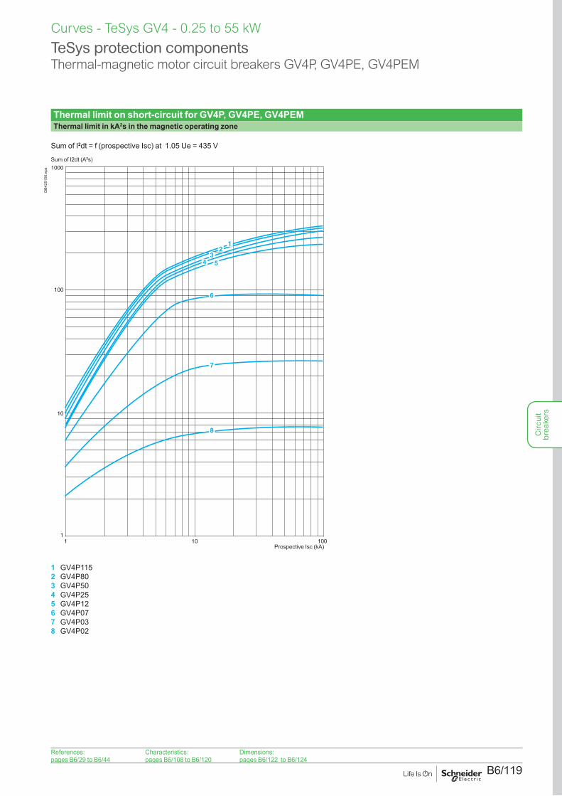
B6/119
Thermal limit on short-circuit for GV4P, GV4PE, GV4PEMThermal limit in kA2s in the magnetic operating zone
Sum of I2dt = f (prospective Isc) at 1.05 Ue = 435 V
1
10
100
1000
1 10 100
12
34 5
6
7
8
Sum of I2dt (A2s)
Prospective Isc (kA)
DB4
2515
6.ep
s
1 GV4P1152 GV4P803 GV4P504 GV4P255 GV4P126 GV4P077 GV4P038 GV4P02
TeSys protection componentsThermal-magnetic motor circuit breakers GV4P, GV4PE, GV4PEM
Curves - TeSys GV4 - 0.25 to 55 kW
References:pages B6/29 to B6/44
Characteristics:pages B6/108 to B6/120
Dimensions:pages B6/122 to B6/124
Circ
uit
brea
kers
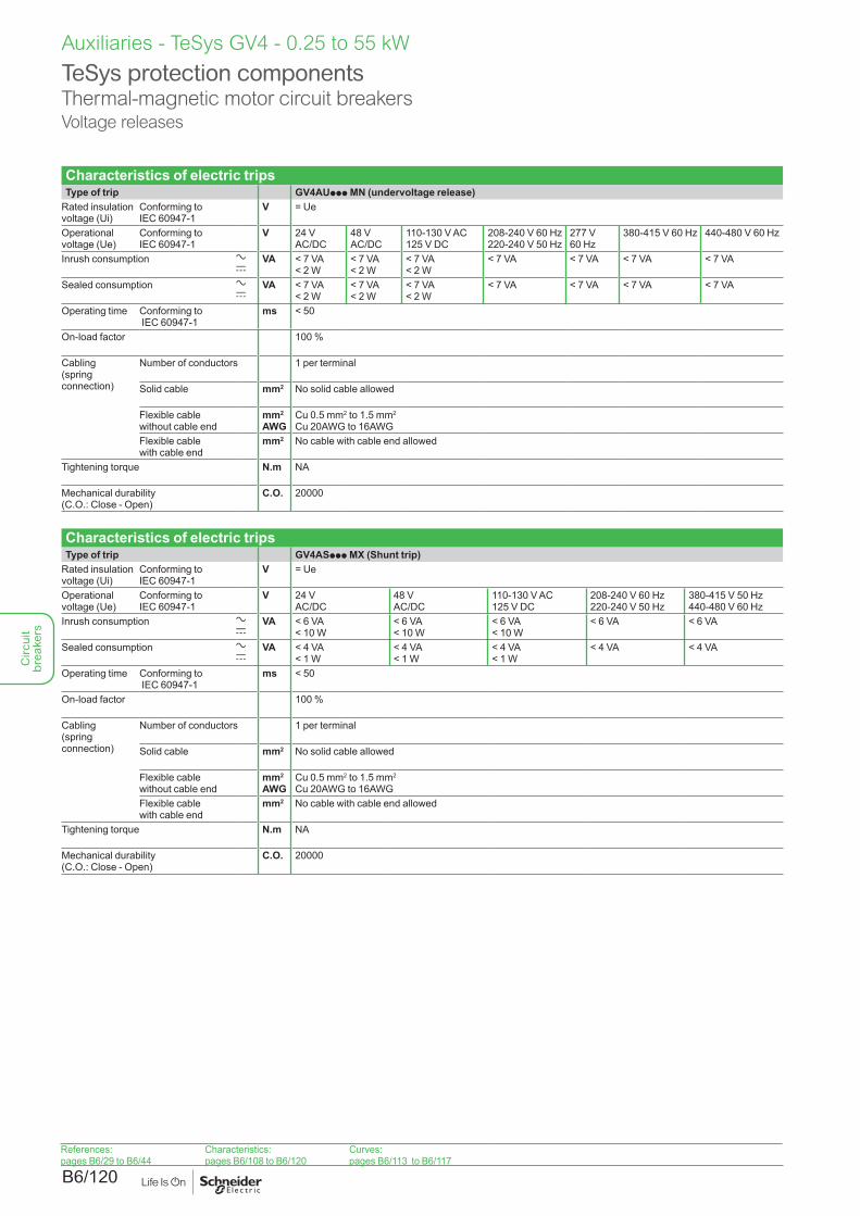
B6/120
Characteristics of electric tripsType of trip GV4AUppp MN (undervoltage release)
Rated insulation voltage (Ui)
Conforming to IEC 60947-1
V = Ue
Operational voltage (Ue)
Conforming to IEC 60947-1
V 24 V AC/DC
48 V AC/DC
110-130 V AC 125 V DC
208-240 V 60 Hz 220-240 V 50 Hz
277 V 60 Hz
380-415 V 60 Hz 440-480 V 60 Hz
Inrush consumption a c
VA < 7 VA < 2 W
< 7 VA < 2 W
< 7 VA < 2 W
< 7 VA < 7 VA < 7 VA < 7 VA
Sealed consumption a c
VA < 7 VA < 2 W
< 7 VA < 2 W
< 7 VA < 2 W
< 7 VA < 7 VA < 7 VA < 7 VA
Operating time Conforming to IEC 60947-1
ms < 50
On-load factor 100 %
Cabling (spring connection)
Number of conductors 1 per terminal
Solid cable mm2 No solid cable allowed
Flexible cable without cable end
mm2
AWGCu 0.5 mm2 to 1.5 mm2
Cu 20AWG to 16AWG Flexible cable with cable end
mm2 No cable with cable end allowed
Tightening torque N.m NA
Mechanical durability (C.O.: Close - Open)
C.O. 20000
Characteristics of electric tripsType of trip GV4ASppp MX (Shunt trip)
Rated insulation voltage (Ui)
Conforming to IEC 60947-1
V = Ue
Operational voltage (Ue)
Conforming to IEC 60947-1
V 24 V AC/DC
48 V AC/DC
110-130 V AC 125 V DC
208-240 V 60 Hz 220-240 V 50 Hz
380-415 V 50 Hz 440-480 V 60 Hz
Inrush consumption a c
VA < 6 VA < 10 W
< 6 VA < 10 W
< 6 VA < 10 W
< 6 VA < 6 VA
Sealed consumption a c
VA < 4 VA < 1 W
< 4 VA < 1 W
< 4 VA < 1 W
< 4 VA < 4 VA
Operating time Conforming to IEC 60947-1
ms < 50
On-load factor 100 %
Cabling (spring connection)
Number of conductors 1 per terminal
Solid cable mm2 No solid cable allowed
Flexible cable without cable end
mm2
AWGCu 0.5 mm2 to 1.5 mm2
Cu 20AWG to 16AWG Flexible cable with cable end
mm2 No cable with cable end allowed
Tightening torque N.m NA
Mechanical durability (C.O.: Close - Open)
C.O. 20000
TeSys protection componentsThermal-magnetic motor circuit breakersVoltage releases
Auxiliaries - TeSys GV4 - 0.25 to 55 kW
References:pages B6/29 to B6/44
Characteristics:pages B6/108 to B6/120
Curves:pages B6/113 to B6/117
Circ
uit
brea
kers
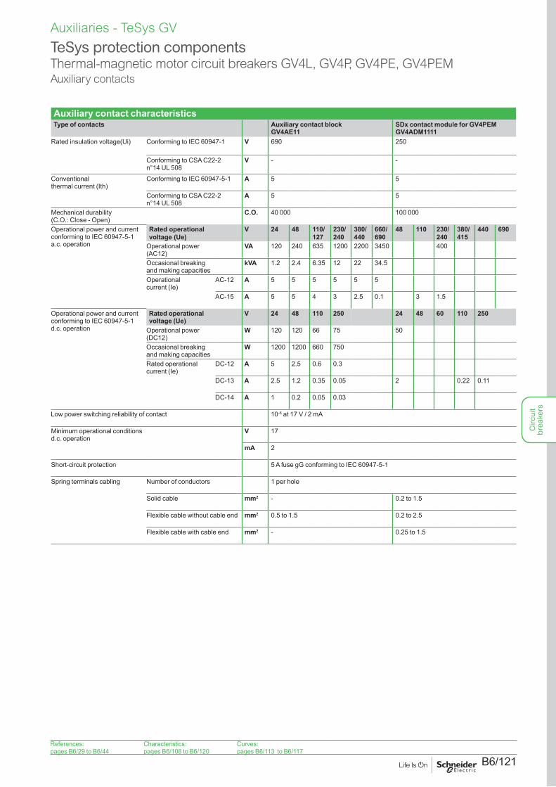
B6/121
Auxiliaries - TeSys GV
Auxiliary contact characteristicsType of contacts Auxiliary contact block
GV4AE11SDx contact module for GV4PEM GV4ADM1111
Rated insulation voltage(Ui) Conforming to IEC 60947-1 V 690 250
Conforming to CSA C22-2 n°14 UL 508
V - -
Conventional thermal current (Ith)
Conforming to IEC 60947-5-1 A 5 5
Conforming to CSA C22-2 n°14 UL 508
A 5 5
Mechanical durability (C.O.: Close - Open)
C.O. 40 000 100 000
Operational power and current conforming to IEC 60947-5-1 a.c. operation
Rated operational voltage (Ue)
V 24 48 110/ 127
230/ 240
380/ 440
660/ 690
48 110 230/ 240
380/ 415
440 690
Operational power (AC12)
VA 120 240 635 1200 2200 3450 400
Occasional breaking and making capacities
kVA 1.2 2.4 6.35 12 22 34.5
Operational current (Ie)
AC-12 A 5 5 5 5 5 5
AC-15 A 5 5 4 3 2.5 0.1 3 1.5
Operational power and current conforming to IEC 60947-5-1 d.c. operation
Rated operational voltage (Ue)
V 24 48 110 250 24 48 60 110 250
Operational power (DC12)
W 120 120 66 75 50
Occasional breaking and making capacities
W 1200 1200 660 750
Rated operational current (Ie)
DC-12 A 5 2.5 0.6 0.3
DC-13 A 2.5 1.2 0.35 0.05 2 0.22 0.11
DC-14 A 1 0.2 0.05 0.03
Low power switching reliability of contact 10-6 at 17 V / 2 mA
Minimum operational conditionsd.c. operation
V 17
mA 2
Short-circuit protection 5 A fuse gG conforming to IEC 60947-5-1
Spring terminals cabling Number of conductors 1 per hole
Solid cable mm2 - 0.2 to 1.5
Flexible cable without cable end mm2 0.5 to 1.5 0.2 to 2.5
Flexible cable with cable end mm2 - 0.25 to 1.5
TeSys protection componentsThermal-magnetic motor circuit breakers GV4L, GV4P, GV4PE, GV4PEMAuxiliary contacts
References:pages B6/29 to B6/44
Characteristics:pages B6/108 to B6/120
Curves:pages B6/113 to B6/117
Circ
uit
brea
kers
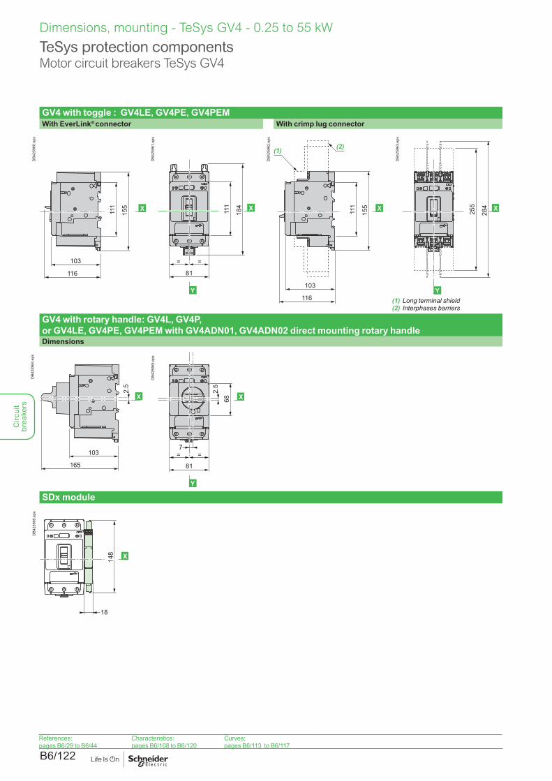
B6/122
Dimensions, mounting - TeSys GV4 - 0.25 to 55 kW
TeSys protection componentsMotor circuit breakers TeSys GV4
GV4 with toggle : GV4LE, GV4PE, GV4PEMWith EverLink® connector With crimp lug connector
X111
155
103
116
DB4
2596
0.ep
s
X
Y
111
184
= =
81
DB4
2596
1.ep
s
103
116
(2)(1)
X111
155
DB4
2596
2.ep
s
X
Y
255
284
DB4
2596
3.ep
s
(1) Long terminal shield(2) Interphases barriers
GV4 with rotary handle: GV4L, GV4P, or GV4LE, GV4PE, GV4PEM with GV4ADN01, GV4ADN02 direct mounting rotary handleDimensions
103
165
2.5
X
DB4
2596
4.ep
s
SDx module
18
148 X
DB4
2596
6.ep
s
References:pages B6/29 to B6/44
Characteristics:pages B6/108 to B6/120
Curves:pages B6/113 to B6/117
X
Y
= =
81
68
2.5
7
DB4
2596
5.ep
s
Circ
uit
brea
kers
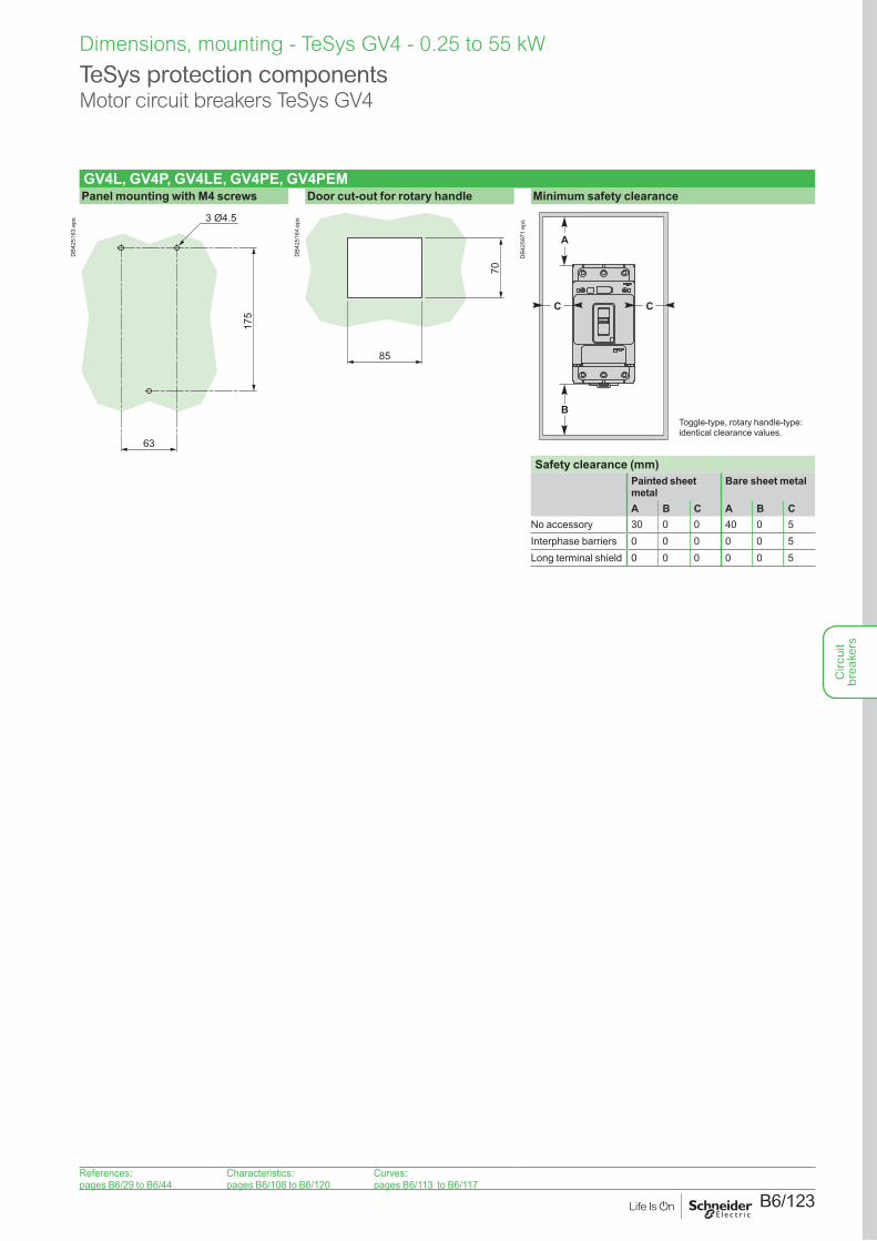
B6/123
Dimensions, mounting - TeSys GV4 - 0.25 to 55 kW
TeSys protection componentsMotor circuit breakers TeSys GV4
GV4L, GV4P, GV4LE, GV4PE, GV4PEMPanel mounting with M4 screws Door cut-out for rotary handle Minimum safety clearance
3 Ø4.5
175
63
DB4
2516
3.ep
s
70
85
DB4
2516
4.ep
s
A
B
C C
DB4
2597
1.ep
s
Safety clearance (mm)Painted sheet metal
Bare sheet metal
A B C A B CNo accessory 30 0 0 40 0 5Interphase barriers 0 0 0 0 0 5Long terminal shield 0 0 0 0 0 5
Toggle-type, rotary handle-type: identical clearance values.
References:pages B6/29 to B6/44
Characteristics:pages B6/108 to B6/120
Curves:pages B6/113 to B6/117
Circ
uit
brea
kers
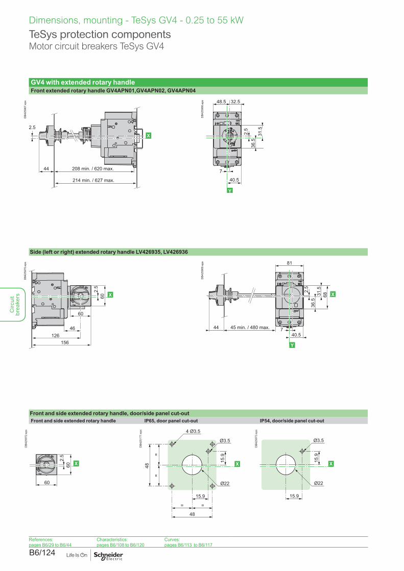
B6/124
Dimensions, mounting - TeSys GV4 - 0.25 to 55 kW
TeSys protection componentsMotor circuit breakers TeSys GV4
GV4 with extended rotary handleFront extended rotary handle GV4APN01,GV4APN02, GV4APN04
208 min. / 620 max.
214 min. / 627 max.
X
44
2.5
DB4
2596
7.ep
s
Trip
O
I
36.5
40.5
32.548.5
7
2.5
6831.5
X
Y
DB4
2596
8.ep
s
Side (left or right) extended rotary handle LV426935, LV426936
46126
156
2.5
60
60 X
DB4
2597
0.ep
s
Trip
O
I
45 min. / 480 max.4440.5
7
2.5
81
36.5
31.5
68 X
Y
DB4
2596
9.ep
s
Front and side extended rotary handle, door/side panel cut-outFront and side extended rotary handle IP65, door panel cut-out IP54, door/side panel cut-out
2.5
60
60 X
DB4
2597
2.ep
s
15.9
4 Ø3.5
Ø3.5
Ø22
15.9
= =
48
==
48 X
DB4
2517
7.ep
s
15.9
Ø3.5
Ø22
15.9
X
DB4
2597
3.ep
s
References:pages B6/29 to B6/44
Characteristics:pages B6/108 to B6/120
Curves:pages B6/113 to B6/117
Circ
uit
brea
kers
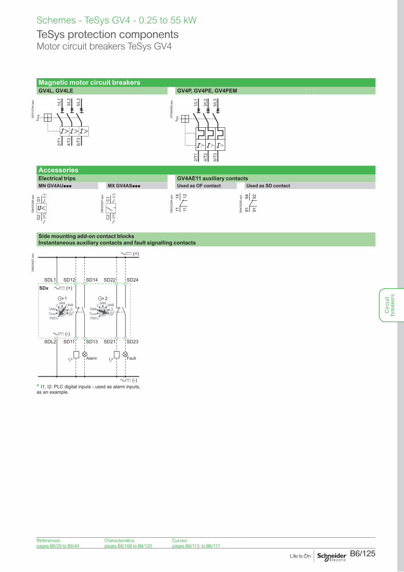
B6/125
Magnetic motor circuit breakersGV4L, GV4LE GV4P, GV4PE, GV4PEM
2/T1
4/T2
6/T3
1/L1
3/L2
5/L3
DF5
1074
4.ep
s
2/T1
4/T2
6/T3
1/L1
3/L2
5/L3
DF5
6906
8.ep
sAccessoriesElectrical trips GV4AE11 auxiliary contactsMN GV4AUppp MX GV4ASppp Used as OF contact Used as SD contact
D1
D2
a (+
)a
(-)
DB4
2528
6.ep
s
a (+
)a
(-)
C1
C2
DB4
2528
7.ep
s
11 11
14 12
DB4
2528
4.ep
s
91 91
94 92
DB4
2528
5.ep
sSide mounting add-on contact blocks Instantaneous auxiliary contacts and fault signalling contacts
* *
* I1, I2: PLC digital inputs - used as alarm inputs,as an example.
T
T95%
TAMUNB
GF
JAM
LSTxxs
T
T95%
TAMUNB
GF
JAM
LSTxxs
a/c (+)
a/c (-)
a/c (-)
a/c (+)SDxSDL1 SD12 SD14 SD22 SD24
SDL2 SD11 SD13 SD21 SD23
Alarm FaultI1 I2
DB4
2592
7.ep
s
References:pages B6/29 to B6/44
Characteristics:pages B6/108 to B6/120
Curves:pages B6/113 to B6/117
Schemes - TeSys GV4 - 0.25 to 55 kW
TeSys protection componentsMotor circuit breakers TeSys GV4
Circ
uit
brea
kers

B6/126
Circ
uit
brea
kers
B6/127
TeSys GV755 to 110 kW
Circ
uit
brea
kers
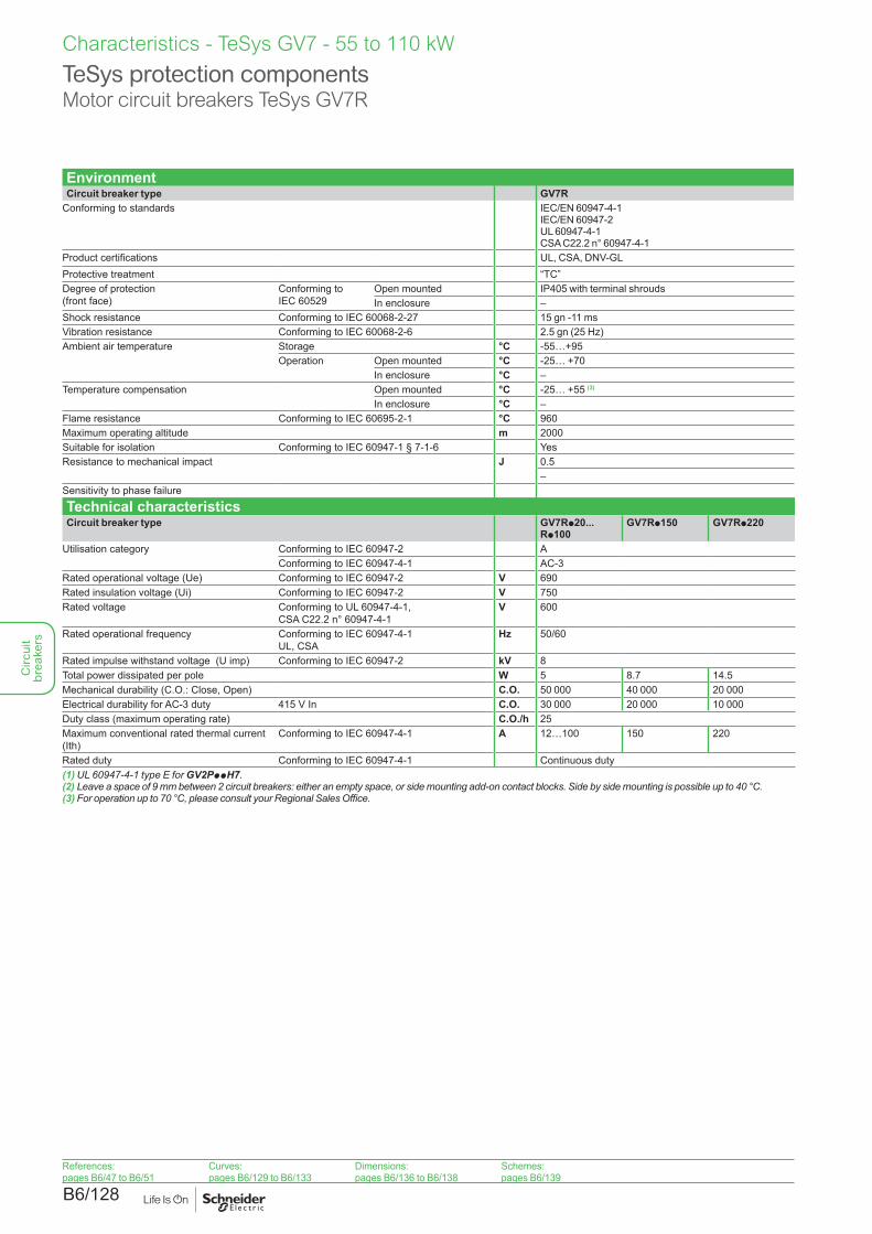
B6/128
Characteristics - TeSys GV7 - 55 to 110 kW
TeSys protection componentsMotor circuit breakers TeSys GV7R
EnvironmentCircuit breaker type GV7R
Conforming to standards IEC/EN 60947-4-1 IEC/EN 60947-2UL 60947-4-1CSA C22.2 n° 60947-4-1
Product certifications UL, CSA, DNV-GLProtective treatment “TC”Degree of protection (front face)
Conforming to IEC 60529
Open mounted IP405 with terminal shroudsIn enclosure –
Shock resistance Conforming to IEC 60068-2-27 15 gn -11 msVibration resistance Conforming to IEC 60068-2-6 2.5 gn (25 Hz)Ambient air temperature Storage °C -55…+95
Operation Open mounted °C -25… +70In enclosure °C –
Temperature compensation Open mounted °C -25… +55 (3)
In enclosure °C –Flame resistance Conforming to IEC 60695-2-1 °C 960Maximum operating altitude m 2000Suitable for isolation Conforming to IEC 60947-1 § 7-1-6 YesResistance to mechanical impact J 0.5
–Sensitivity to phase failure
Technical characteristicsCircuit breaker type GV7Rp20...
Rp100GV7Rp150 GV7Rp220
Utilisation category Conforming to IEC 60947-2 AConforming to IEC 60947-4-1 AC-3
Rated operational voltage (Ue) Conforming to IEC 60947-2 V 690Rated insulation voltage (Ui) Conforming to IEC 60947-2 V 750Rated voltage Conforming to UL 60947-4-1,
CSA C22.2 n° 60947-4-1V 600
Rated operational frequency Conforming to IEC 60947-4-1 UL, CSA
Hz 50/60
Rated impulse withstand voltage (U imp) Conforming to IEC 60947-2 kV 8Total power dissipated per pole W 5 8.7 14.5Mechanical durability (C.O.: Close, Open) C.O. 50 000 40 000 20 000Electrical durability for AC-3 duty 415 V In C.O. 30 000 20 000 10 000Duty class (maximum operating rate) C.O./h 25Maximum conventional rated thermal current (Ith)
Conforming to IEC 60947-4-1 A 12…100 150 220
Rated duty Conforming to IEC 60947-4-1 Continuous duty(1) UL 60947-4-1 type E for GV2PppH7.(2) Leave a space of 9 mm between 2 circuit breakers: either an empty space, or side mounting add-on contact blocks. Side by side mounting is possible up to 40 °C.(3) For operation up to 70 °C, please consult your Regional Sales Office.
References:pages B6/47 to B6/51
Curves:pages B6/129 to B6/133
Dimensions:pages B6/136 to B6/138
Schemes:pages B6/139
Circ
uit
brea
kers
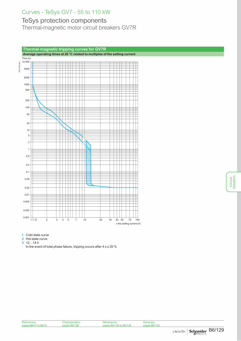
B6/129
Curves - TeSys GV7 - 55 to 110 kW
Thermal-magnetic tripping curves for GV7RAverage operating times at 20 °C related to multiples of the setting current
0,001
0,002
0,1
0,01
0,005
0,05
1
0,5
0,02
0,2
2
5
10
20
50
100
200
500
1000
2000
5000
10 000
102 3 4 7 10020 30 405 50 701
3
1
1,12
2
Time (s)
x the setting current (Ir)
DF5
1074
5.ep
s
1 Cold state curve2 Hot state curve3 12…14 Ir
In the event of total phase failure, tripping occurs after 4 s ± 20 %
TeSys protection componentsThermal-magnetic motor circuit breakers GV7R
References:pages B6/47 to B6/51
Characteristics:pages B6/128
Dimensions:pages B6/136 to B6/138
Schemes:pages B6/139
Circ
uit
brea
kers
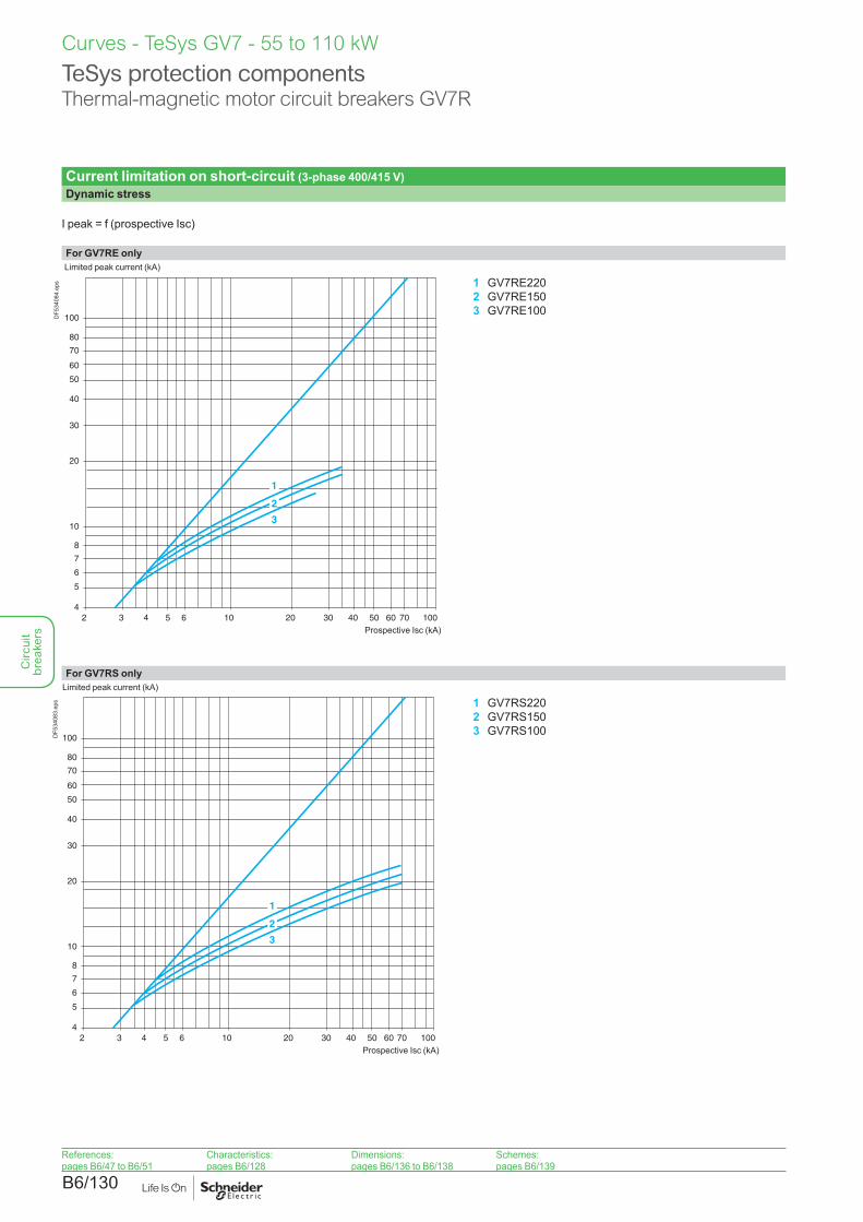
B6/130
Curves - TeSys GV7 - 55 to 110 kW
TeSys protection componentsThermal-magnetic motor circuit breakers GV7R
Current limitation on short-circuit (3-phase 400/415 V)Dynamic stress
I peak = f (prospective Isc)
For GV7RE only
4102
5
7
60
20
10
50
100
30
3 4 6 10020 30 40 60
40
70
5 50
1
2
3
6
8
80
70
Limited peak current (kA)
Prospective Isc (kA)
DF5
3408
4.ep
s 1 GV7RE2202 GV7RE1503 GV7RE100
For GV7RS only
4102
5
7
60
20
10
50
100
30
3 4 6 10020 30 40 60
40
70
5 50
6
8
80
1
2
3
70
Limited peak current (kA)
Prospective Isc (kA)
DF5
3408
3.ep
s 1 GV7RS2202 GV7RS1503 GV7RS100
References:pages B6/47 to B6/51
Characteristics:pages B6/128
Dimensions:pages B6/136 to B6/138
Schemes:pages B6/139
Circ
uit
brea
kers
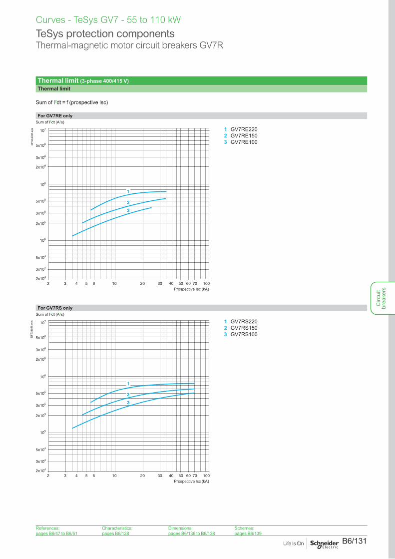
B6/131
Curves - TeSys GV7 - 55 to 110 kW
TeSys protection componentsThermal-magnetic motor circuit breakers GV7R
Thermal limit (3-phase 400/415 V)Thermal limit
Sum of I2dt = f (prospective Isc)
For GV7RE only
2x10⁴
102
3x10⁴
5x10⁴
2x10⁶
2x10⁵
105
106
107
5x10⁶
3x10⁵
3 4 6 10020 30 40 60
5x10⁵
3x10⁶
5 50 70
1
2
3
Sum of I2dt (A2s)
Prospective Isc (kA)
DF5
3408
5.ep
s 1 GV7RE2202 GV7RE1503 GV7RE100
For GV7RS only
2x10⁴
102
3x10⁴
5x10⁴
2x10⁶
2x10⁵
105
106
107
5x10⁶
3x10⁵
3 4 6 10020 30 40 60
5x10⁵
3x10⁶
5 50 70
1
2
3
Sum of I2dt (A2s)
Prospective Isc (kA)
DF5
3408
6.ep
s 1 GV7RS2202 GV7RS1503 GV7RS100
References:pages B6/47 to B6/51
Characteristics:pages B6/128
Dimensions:pages B6/136 to B6/138
Schemes:pages B6/139
Circ
uit
brea
kers
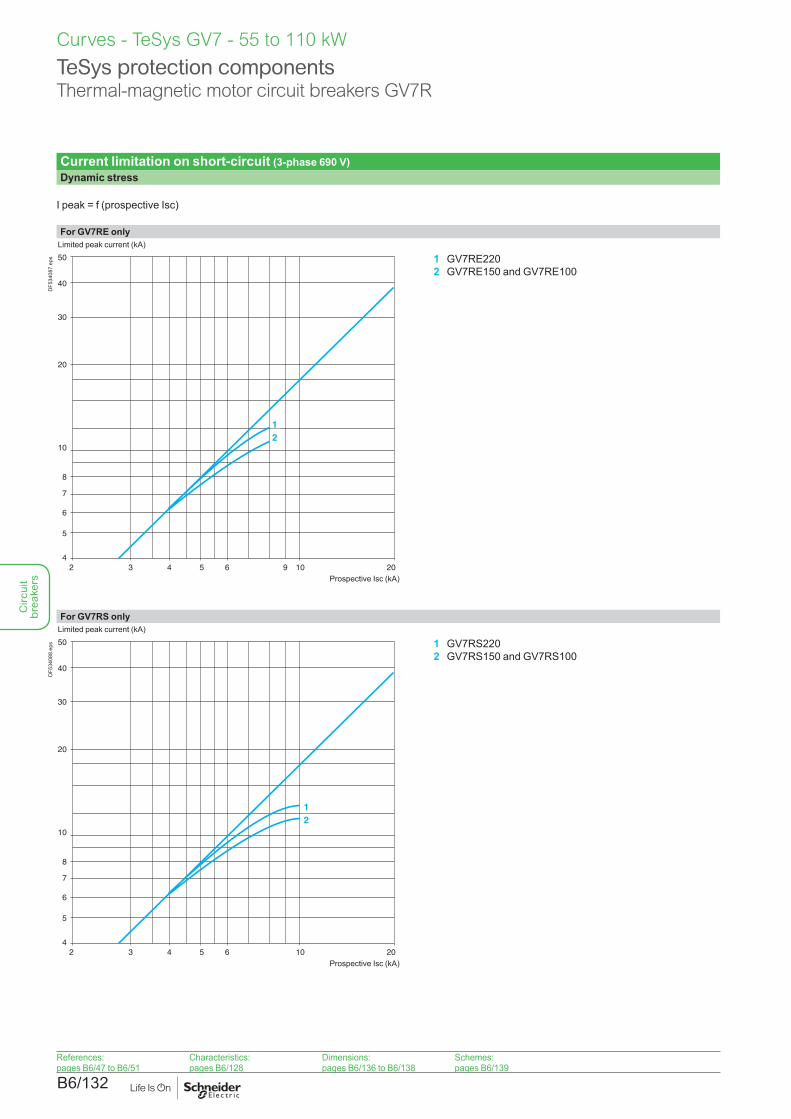
B6/132
TeSys protection componentsThermal-magnetic motor circuit breakers GV7R
Current limitation on short-circuit (3-phase 690 V)Dynamic stress
I peak = f (prospective Isc)
For GV7RE only
4102
5
6
30
10
8
20
50
40
3 4 6 205
12
7
9
Limited peak current (kA)
Prospective Isc (kA)
DF5
3408
7.ep
s 1 GV7RE2202 GV7RE150 and GV7RE100
For GV7RS only
4102
5
6
30
10
8
20
50
40
3 4 6 205
12
7
Limited peak current (kA)
Prospective Isc (kA)
DF5
3408
8.ep
s 1 GV7RS2202 GV7RS150 and GV7RS100
References:pages B6/47 to B6/51
Characteristics:pages B6/128
Dimensions:pages B6/136 to B6/138
Schemes:pages B6/139
Curves - TeSys GV7 - 55 to 110 kWC
ircui
t br
eake
rs
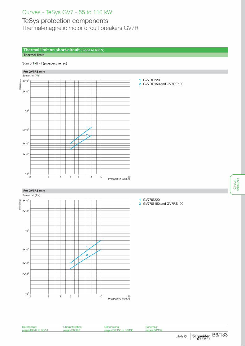
B6/133
TeSys protection componentsThermal-magnetic motor circuit breakers GV7R
Thermal limit on short-circuit (3-phase 690 V)Thermal limit
Sum of I2dt = f (prospective Isc)
For GV7RE only
102 3 4 6 205
2x10⁶
2x10⁵
105
106
3x10⁵
5x10⁵
3x10⁶
1
2
8
Sum of I2dt (A2s)
Prospective Isc (kA)
DF5
3408
9.ep
s 1 GV7RE2202 GV7RE150 and GV7RE100
For GV7RS only
102 3 4 6 205
2x10⁶
2x10⁵
105
106
3x10⁵
5x10⁵
3x10⁶
1
2
Sum of I2dt (A2s)
Prospective Isc (kA)
DF5
3409
0.ep
s 1 GV7RS2202 GV7RS150 and GV7RS100
References:pages B6/47 to B6/51
Characteristics:pages B6/128
Dimensions:pages B6/136 to B6/138
Schemes:pages B6/139
Curves - TeSys GV7 - 55 to 110 kW
Circ
uit
brea
kers
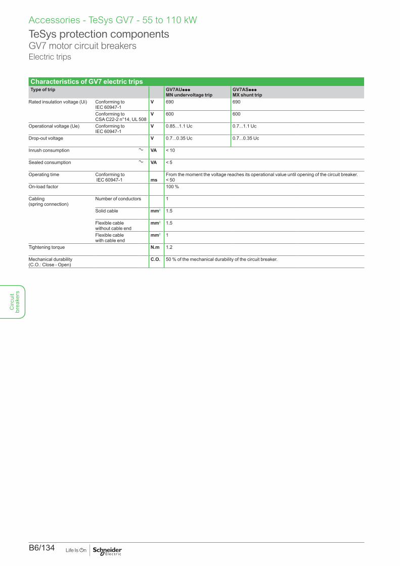
B6/134
Characteristics of GV7 electric tripsType of trip GV7AUppp
MN undervoltage tripGV7ASppp MX shunt trip
Rated insulation voltage (Ui) Conforming to IEC 60947-1
V 690 690
Conforming to CSA C22-2 n°14, UL 508
V 600 600
Operational voltage (Ue) Conforming to IEC 60947-1
V 0.85...1.1 Uc 0.7...1.1 Uc
Drop-out voltage V 0.7...0.35 Uc 0.7...0.35 Uc
Inrush consumption a VA < 10
Sealed consumption a VA < 5
Operating time Conforming to IEC 60947-1
ms
From the moment the voltage reaches its operational value until opening of the circuit breaker. < 50
On-load factor 100 %
Cabling (spring connection)
Number of conductors 1
Solid cable mm2 1.5
Flexible cable without cable end
mm2 1.5
Flexible cable with cable end
mm2 1
Tightening torque N.m 1.2
Mechanical durability (C.O.: Close - Open)
C.O. 50 % of the mechanical durability of the circuit breaker.
TeSys protection componentsGV7 motor circuit breakersElectric trips
Accessories - TeSys GV7 - 55 to 110 kWC
ircui
t br
eake
rs
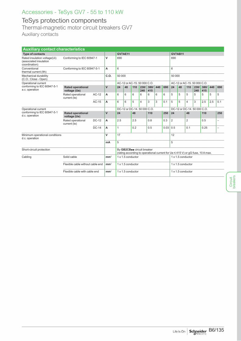
B6/135
Accessories - TeSys GV7 - 55 to 110 kW
Auxiliary contact characteristicsType of contacts GV7AE11 GV7AB11
Rated insulation voltage(Ui) (associated insulation coordination)
Conforming to IEC 60947-1 V 690 690
Conventional thermal current (Ith)
Conforming to IEC 60947-5-1 A 6 6
Mechanical durability (C.O.: Close - Open)
C.O. 50 000 50 000
Operational current conforming to IEC 60947-5-1 a.c. operation
AC-12 or AC-15. 50 000 C.O. AC-12 or AC-15. 50 000 C.O.Rated operational voltage (Ue)
V 24 48 110 230/ 240
380/ 415
440 690 24 48 110 230/ 240
380/ 415
440 690
Rated operational current (Ie)
AC-12 A 6 6 6 6 6 6 6 5 5 5 5 5 5 5
AC-15 A 6 6 5 4 3 3 0.1 5 5 4 3 2.5 2.5 0.1
Operational current conforming to IEC 60947-5-1 d.c. operation
DC-12 or DC-14. 50 000 C.O. DC-12 or DC-14. 50 000 C.O.Rated operational voltage (Ue)
V 24 48 110 250 24 48 110 250
Rated operational current (Ie)
DC-12 A 2.5 2.5 0.8 0.3 2 2 0.5 –
DC-14 A 1 0.2 0.5 0.03 0.5 0.1 0.25 –
Minimum operational conditionsd.c. operation
V 17 12
mA 5 5
Short-circuit protection By GB2CBpp circuit breaker (rating according to operational current for Ue y 415 V) or gG fuse, 10 A max.
Cabling Solid cable mm2 1 x 1.5 conductor 1 x 1.5 conductor
Flexible cable without cable end mm2 1 x 1.5 conductor 1 x 1.5 conductor
Flexible cable with cable end mm2 1 x 1.5 conductor 1 x 1.5 conductor
TeSys protection componentsThermal-magnetic motor circuit breakers GV7Auxiliary contacts
Circ
uit
brea
kers
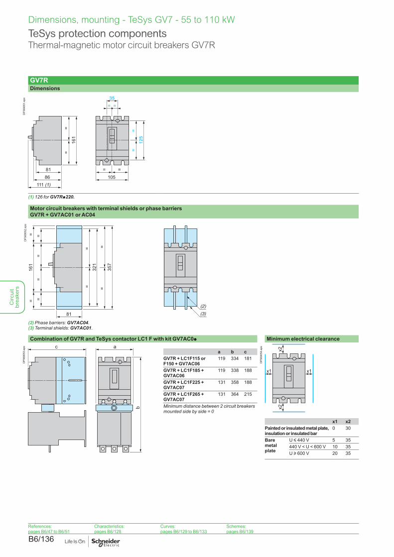
B6/136
Dimensions, mounting - TeSys GV7 - 55 to 110 kW
TeSys protection componentsThermal-magnetic motor circuit breakers GV7R
GV7RDimensions
8186
111 (1)
=16
1=
=
=12
5=
105
= =35
=
DF5
6905
1.ep
s
(1) 126 for GV7Rp220.
Motor circuit breakers with terminal shields or phase barriers GV7R + GV7AC01 or AC04
DF5
6905
2.ep
s
(2) Phase barriers: GV7AC04.(3) Terminal shields: GV7AC01.
Combination of GV7R and TeSys contactor LC1 F with kit GV7AC0p Minimum electrical clearanceac
b
DF5
6905
3.ep
s
x1x1
x2x2
DF5
6905
4.ep
s
a b cGV7R + LC1F115 or F150 + GV7AC06
119 334 181
GV7R + LC1F185 + GV7AC06
119 338 188
GV7R + LC1F225 + GV7AC07
131 358 188
GV7R + LC1F265 + GV7AC07
131 364 215
Minimum distance between 2 circuit breakers mounted side by side = 0
x1 x2Painted or insulated metal plate, insulation or insulated bar
0 30
Bare metal plate
U y 440 V 5 35440 V < U < 600 V 10 35U u 600 V 20 35
References:pages B6/47 to B6/51
Characteristics:pages B6/128
Curves:pages B6/129 to B6/133
Schemes:pages B6/139
Circ
uit
brea
kers
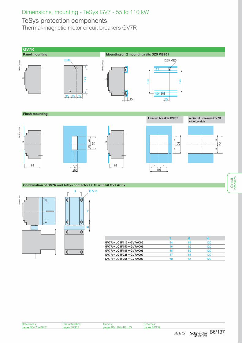
B6/137
Dimensions, mounting - TeSys GV7 - 55 to 110 kW
TeSys protection componentsThermal-magnetic motor circuit breakers GV7R
GV7RPanel mounting Mounting on 2 mounting rails DZ5 MB201
35
=12
5
35 35
=
DF5
6905
6.ep
s
135
35
125
DZ5 ME5
15D
F569
057.
eps
Flush-mounting1 circuit breaker GV7R n circuit breakers GV7R
side by side
=
29
=29
4776
88 83
==
108
= =108
==
108
DF5
6905
8.ep
s
Combination of GV7R and TeSys contactor LC1F with kit GV7 AC0p
G
EH
DF5
6905
5.ep
s
E G HGV7R + LC1F115 + GV7AC06 44 85 120GV7R + LC1F150 + GV7AC06 46 85 120GV7R + LC1F185 + GV7AC06 48 85 120GV7R + LC1F225 + GV7AC07 57 85 120GV7R + LC1F265 + GV7AC07 60 85 120
References:pages B6/47 to B6/51
Characteristics:pages B6/128
Curves:pages B6/129 to B6/133
Schemes:pages B6/139
Circ
uit
brea
kers
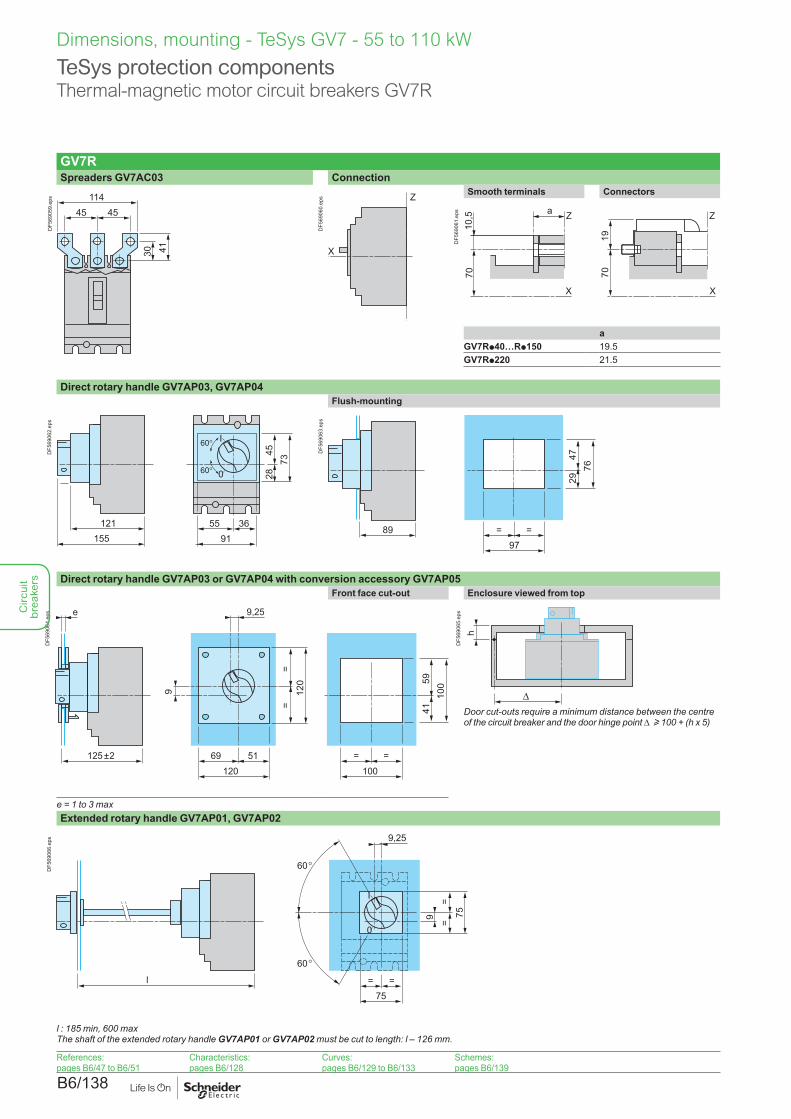
B6/138
Dimensions, mounting - TeSys GV7 - 55 to 110 kW
TeSys protection componentsThermal-magnetic motor circuit breakers GV7R
GV7RSpreaders GV7AC03 Connection
45 45114
30 41
DF5
6905
9.ep
s Z
X
DF5
6906
0.ep
s
Smooth terminals Connectors
X
7010
,5 Z
70
Z
X
19
a
DF5
6906
1.ep
s
aGV7Rp40…Rp150 19.5GV7Rp220 21.5
Direct rotary handle GV7AP03, GV7AP04Flush-mounting
7345
28
155121
0
I
5591
36
DF5
6906
2.ep
s
=
29
=97
4776
89
DF5
6906
3.ep
s
Direct rotary handle GV7AP03 or GV7AP04 with conversion accessory GV7AP05Front face cut-out Enclosure viewed from top
=
41
=100
5910
0
69
=
51120
=12
0
125 ±2
e
9
9,25
DF5
6906
4.ep
s
hD
F569
065.
eps
Door cut-outs require a minimum distance between the centre of the circuit breaker and the door hinge point D u 100 + (h x 5)
e = 1 to 3 maxExtended rotary handle GV7AP01, GV7AP02
75=
60
60
0
I
=
75=
=
l
9
9,25
DF5
6906
6.ep
s
l : 185 min, 600 maxThe shaft of the extended rotary handle GV7AP01 or GV7AP02 must be cut to length: l – 126 mm.
References:pages B6/47 to B6/51
Characteristics:pages B6/128
Curves:pages B6/129 to B6/133
Schemes:pages B6/139
Circ
uit
brea
kers
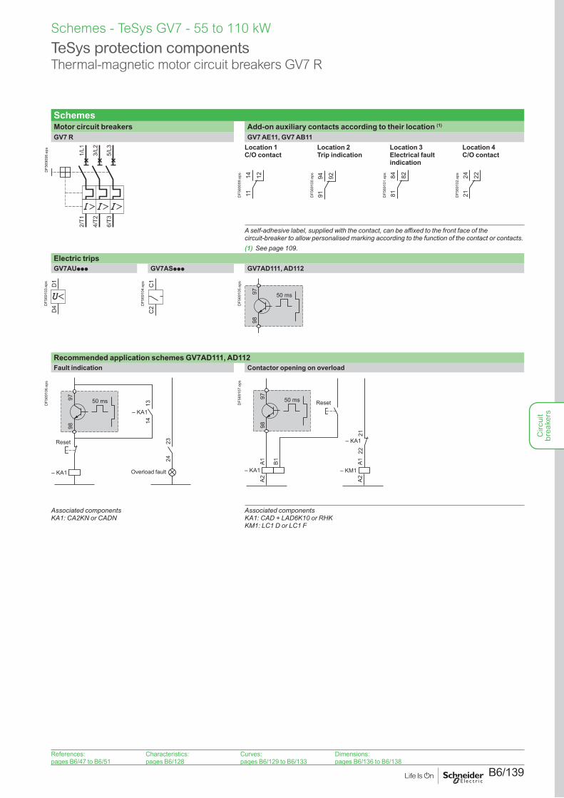
B6/139
Schemes - TeSys GV7 - 55 to 110 kW
TeSys protection componentsThermal-magnetic motor circuit breakers GV7 R
SchemesMotor circuit breakers Add-on auxiliary contacts according to their location (1)
GV7 R GV7 AE11, GV7 AB11
2/T1
4/T2
6/T3
1/L1
3/L2
5/L3
DF5
6909
8.ep
s Location 1C/O contact
Location 2 Trip indication
Location 3 Electrical fault indication
Location 4 C/O contact
1114 12
DF5
6909
9.ep
s
9194 92
DF5
6910
0.ep
s
8184 82
DF5
6910
1.ep
s
2124 22
DF5
6910
2.ep
s
A self-adhesive label, supplied with the contact, can be affixed to the front face of the circuit-breaker to allow personalised marking according to the function of the contact or contacts.(1) See page 109.
Electric tripsGV7AUppp GV7ASppp GV7AD111, AD112
D1
D4D
F569
103.
eps
C1
C2D
F569
104.
eps
9897 50 ms
DF5
6910
5.ep
s
Recommended application schemes GV7AD111, AD112Fault indication Contactor opening on overload
9897 50 ms
– KA1
2324
1314
– KA1
Reset
Overload fault
DF5
6910
6.ep
s
9897 50 ms
– KM1– KA1
A1A2
A1A2
B1
– KA1
2122
ResetDF5
6910
7.ep
s
Associated componentsKA1: CA2KN or CADN
Associated componentsKA1: CAD + LAD6K10 or RHKKM1: LC1 D or LC1 F
References:pages B6/47 to B6/51
Characteristics:pages B6/128
Curves:pages B6/129 to B6/133
Dimensions:pages B6/136 to B6/138
Circ
uit
brea
kers

B6/140
Circ
uit
brea
kers
B6/141
TeSys GB20.5 to 20 A (for equipment and control circuits)
Circ
uit
brea
kers
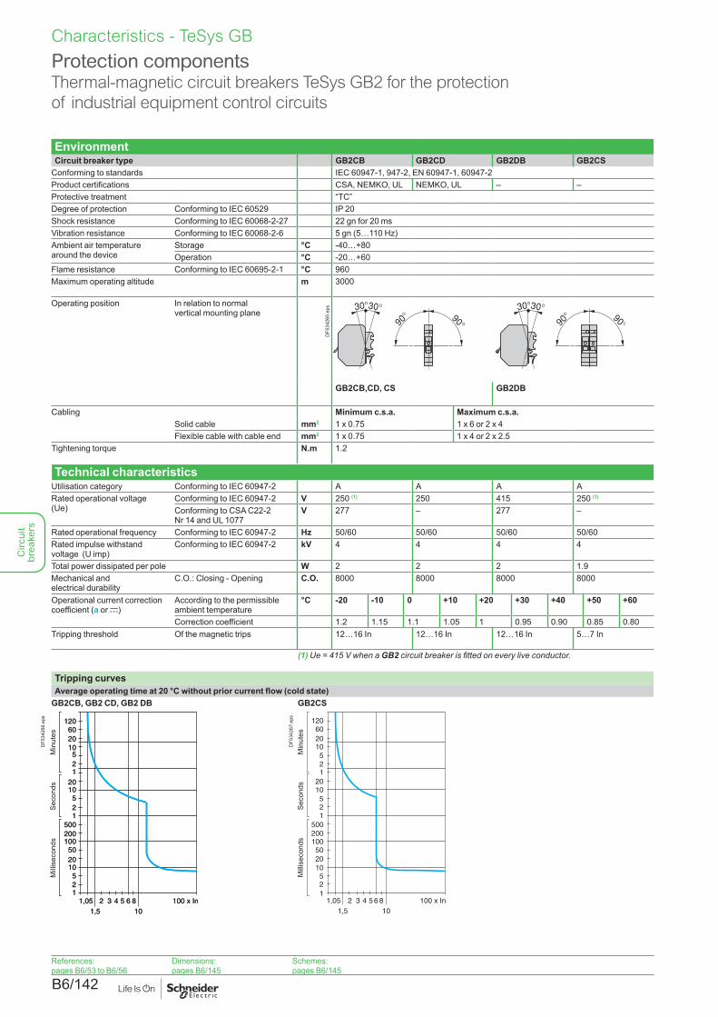
B6/142
EnvironmentCircuit breaker type GB2CB GB2CD GB2DB GB2CS
Conforming to standards IEC 60947-1, 947-2, EN 60947-1, 60947-2Product certifications CSA, NEMKO, UL NEMKO, UL – –Protective treatment “TC”Degree of protection Conforming to IEC 60529 IP 20Shock resistance Conforming to IEC 60068-2-27 22 gn for 20 msVibration resistance Conforming to IEC 60068-2-6 5 gn (5…110 Hz)Ambient air temperature around the device
Storage °C -40…+80Operation °C -20…+60
Flame resistance Conforming to IEC 60695-2-1 °C 960Maximum operating altitude m 3000
Operating position In relation to normal vertical mounting plane
DF5
3426
5.ep
s
GB2CB,CD, CS GB2DB
Cabling Minimum c.s.a. Maximum c.s.a.Solid cable mm2 1 x 0.75 1 x 6 or 2 x 4Flexible cable with cable end mm2 1 x 0.75 1 x 4 or 2 x 2.5
Tightening torque N.m 1.2
Technical characteristicsUtilisation category Conforming to IEC 60947-2 A A A ARated operational voltage (Ue)
Conforming to IEC 60947-2 V 250 (1) 250 415 250 (1)
Conforming to CSA C22-2 Nr 14 and UL 1077
V 277 – 277 –
Rated operational frequency Conforming to IEC 60947-2 Hz 50/60 50/60 50/60 50/60Rated impulse withstand voltage (U imp)
Conforming to IEC 60947-2 kV 4 4 4 4
Total power dissipated per pole W 2 2 2 1.9Mechanical and electrical durability
C.O.: Closing - Opening C.O. 8000 8000 8000 8000
Operational current correction coefficient (a or c)
According to the permissible ambient temperature
°C -20 -10 0 +10 +20 +30 +40 +50 +60
Correction coefficient 1.2 1.15 1.1 1.05 1 0.95 0.90 0.85 0.80Tripping threshold Of the magnetic trips 12…16 In 12…16 In 12…16 In 5…7 In
(1) Ue = 415 V when a GB2 circuit breaker is fitted on every live conductor.
Tripping curvesAverage operating time at 20 °C without prior current flow (cold state)
GB2CB, GB2 CD, GB2 DB GB2CS
1,051,5
2 3 4 5 6 810
1
52
2010
10050
1
52
2010
1
52
2010
60120
500200
100 x In1,051,5
2 3 4 5 6 810
1
52
2010
10050
1
52
2010
1
52
2010
60120
500200
100 x In
Milli
seco
nds
Seco
nds
Min
utes
DF5
3426
6.ep
s
1,051,5
2 3 4 5 6 810
1
52
2010
10050
1
52
2010
1
52
2010
60120
500200
100 x In
Milli
seco
nds
Seco
nds
Min
utes
DF5
3426
7.ep
s
Protection componentsThermal-magnetic circuit breakers TeSys GB2 for the protection of industrial equipment control circuits
Characteristics - TeSys GB
References:pages B6/53 to B6/56
Dimensions:pages B6/145
Schemes:pages B6/145
Circ
uit
brea
kers
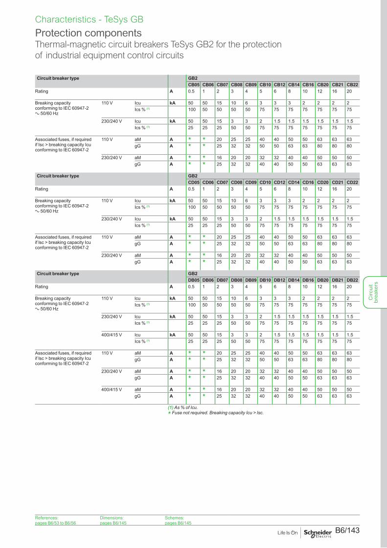
B6/143
Circuit breaker type GB2CB05 CB06 CB07 CB08 CB09 CB10 CB12 CB14 CB16 CB20 CB21 CB22
Rating A 0.5 1 2 3 4 5 6 8 10 12 16 20
Breaking capacity conforming to IEC 60947-2 a 50/60 Hz
110 V Icu kA 50 50 15 10 6 3 3 3 2 2 2 2Ics % (1) 100 50 50 50 50 75 75 75 75 75 75 75
230/240 V Icu kA 50 50 15 3 3 2 1.5 1.5 1.5 1.5 1.5 1.5Ics % (1) 25 25 25 50 50 75 75 75 75 75 75 75
Associated fuses, if required if Isc > breaking capacity Icu conforming to IEC 60947-2
110 V aM A g g 20 25 25 40 40 50 50 63 63 63gG A g g 25 32 32 50 50 63 63 80 80 80
230/240 V aM A g g 16 20 20 32 32 40 40 50 50 50gG A g g 25 32 32 40 40 50 50 63 63 63
Circuit breaker type GB2CD05 CD06 CD07 CD08 CD09 CD10 CD12 CD14 CD16 CD20 CD21 CD22
Rating A 0.5 1 2 3 4 5 6 8 10 12 16 20
Breaking capacity conforming to IEC 60947-2 a 50/60 Hz
110 V Icu kA 50 50 15 10 6 3 3 3 2 2 2 2Ics % (1) 100 50 50 50 50 75 75 75 75 75 75 75
230/240 V Icu kA 50 50 15 3 3 2 1.5 1.5 1.5 1.5 1.5 1.5Ics % (1) 25 25 25 50 50 75 75 75 75 75 75 75
Associated fuses, if required if lsc > breaking capacity Icu conforming to IEC 60947-2
110 V aM A g g 20 25 25 40 40 50 50 63 63 63gG A g g 25 32 32 50 50 63 63 80 80 80
230/240 V aM A g g 16 20 20 32 32 40 40 50 50 50gG A g g 25 32 32 40 40 50 50 63 63 63
Circuit breaker type GB2DB05 DB06 DB07 DB08 DB09 DB10 DB12 DB14 DB16 DB20 DB21 DB22
Rating A 0.5 1 2 3 4 5 6 8 10 12 16 20
Breaking capacity conforming to IEC 60947-2 a 50/60 Hz
110 V lcu kA 50 50 15 10 6 3 3 3 2 2 2 2Ics % (1) 100 50 50 50 50 75 75 75 75 75 75 75
230/240 V lcu kA 50 50 15 3 3 2 1.5 1.5 1.5 1.5 1.5 1.5Ics % (1) 25 25 25 50 50 75 75 75 75 75 75 75
400/415 V lcu kA 50 50 15 3 3 2 1.5 1.5 1.5 1.5 1.5 1.5Ics % (1) 25 25 25 50 50 75 75 75 75 75 75 75
Associated fuses, if required if lsc > breaking capacity Icu conforming to IEC 60947-2
110 V aM A g g 20 25 25 40 40 50 50 63 63 63gG A g g 25 32 32 50 50 63 63 80 80 80
230/240 V aM A g g 16 20 20 32 32 40 40 50 50 50gG A g g 25 32 32 40 40 50 50 63 63 63
400/415 V aM A g g 16 20 20 32 32 40 40 50 50 50gG A g g 25 32 32 40 40 50 50 63 63 63
(1) As % of Icu.g Fuse not required. Breaking capacity Icu > lsc.
Protection componentsThermal-magnetic circuit breakers TeSys GB2 for the protection of industrial equipment control circuits
Characteristics - TeSys GB
References:pages B6/53 to B6/56
Dimensions:pages B6/145
Schemes:pages B6/145
Circ
uit
brea
kers
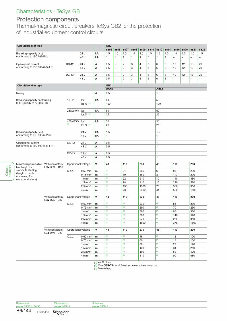
B6/144
Circuit breaker type GB2pp05 pp06 pp07 pp08 pp09 pp10 pp12 pp14 pp16 pp20 pp21 pp22
Breaking capacity (lcu) conforming to IEC 60947-2 c
24 V kA 1.5 1.5 1.5 1.5 1.5 1.5 1.5 1.5 1.5 1.5 1.5 1.548 V kA 1 1 1 1 1 1 1 1 – – – –
Operational current conforming to IEC 60947-5-1 c
DC-12 24 V A 0.5 1 2 3 4 5 6 8 10 12 16 2048 V A 0.5 1 2 3 4 5 6 8 10 12 16 20
DC-13 24 V A 0.5 1 2 3 4 5 6 8 10 12 16 2048 V A 0.5 1 2 3 4 5 6 8 – – – –
Circuit breaker type GB2CS05 CS06
Rating A 0.5 1
Breaking capacity conforming to IEC 60947-2 a 50/60 Hz
110 V lcu kA 50 50lcs % (1) 100 100
230/240 V lcu kA 50 50lcs % (1) 25 25
400/415 V (2)
lcu kA 50 50lcs % (1) 25 25
Breaking capacity (lcu) conforming to IEC 60947-2 c
24 V kA 1.5 1.548 V kA 1 1
Operational current conforming to IEC 60947-5-1 c
DC-12 24 V A 0.5 148 V A 0.5 1
DC-13 24 V A 0.5 148 V A 0.5 1
Maximum permissible line length for star-delta starting (length of cable containing 2 or more conductors)
With contactors LCp D09 …D18
Operational voltage V 48 110 230 48 110 230
C.s.a. 0.60 mm2 m (3) 31 365 6 85 2300.75 mm2 m (3) 39 460 8 110 2901 mm2 m (3) 52 610 10 145 3801.5 mm2 m (3) 78 910 15 220 5702.5 mm2 m (3) 130 1520 26 360 9504 mm2 m (3) 200 2400 41 580 1500
With contactors LCp D25…D32
Operational voltage V 48 110 230 48 110 230
C.s.a. 0.60 mm2 m (3) (3) 230 (3) 56 2300.75 mm2 m (3) (3) 290 (3) 70 2901 mm2 m (3) (3) 390 (3) 95 3801.5 mm2 m (3) (3) 580 (3) 140 5702.5 mm2 m (3) (3) 970 (3) 230 9504 mm2 m (3) (3) 1500 (3) 375 1500
With contactors LCp D40…D80
Operational voltage V 48 110 230 48 110 230
C.s.a. 0.60 mm2 m (3) (3) 46 (3) 13 1000.75 mm2 m (3) (3) 60 (3) 17 1301 mm2 m (3) (3) 80 (3) 22 1701.5 mm2 m (3) (3) 120 (3) 34 2502.5 mm2 m (3) (3) 190 (3) 56 4204 mm2 m (3) (3) 310 (3) 90 680
(1) As % of Icu.(2) One GB2CS circuit breaker on each live conductor.(3) Use relays.
Protection componentsThermal-magnetic circuit breakers TeSys GB2 for the protection of industrial equipment control circuits
Characteristics - TeSys GB
References:pages B6/53 to B6/56
Dimensions:pages B6/145
Schemes:pages B6/145
Circ
uit
brea
kers
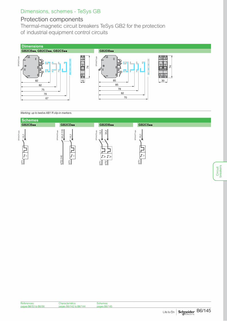
B6/145
DimensionsGB2CBpp, GB2CDpp, GB2CSpp GB2DBpp
74
1582
82
75
79
67
DF5
3427
2.ep
s
30
74
85
85
78
82
70D
F534
273.
eps
Marking: up to twelve AB1 R clip-in markers.
SchemesGB2CBpp GB2CDpp GB2DBpp GB2CSpp
2/T
11/
L1
DF5
3427
4.ep
s
2/T
11/
L1
3/L2
(13
) 4
/T2
( 14)
DF5
3427
5.ep
s
1/L1
3/L2
2/T
1
4/T
2
DF5
3427
6.ep
s
2/T
11/
L1
DF5
3427
7.ep
s
Protection componentsThermal-magnetic circuit breakers TeSys GB2 for the protection of industrial equipment control circuits
Dimensions, schemes - TeSys GB
References:pages B6/53 to B6/56
Characteristics:pages B6/142 to B6/144
Schemes:pages B6/145
Circ
uit
brea
kers

B6/146
Circ
uit
brea
kers

B6/147
Circ
uit
brea
kers

B6/148
Circ
uit
brea
kers