technical specifications repair water main, … specifications . repair water main, tri-intersection...
TRANSCRIPT

TECHNICAL SPECIFICATIONS
Repair Water Main, Tri-Intersection to Stadium Boulevard
100% For Construction
United States Air Force Academy
XQPZ 06-2002
February 2014
ARCHITECTURE ° ENGINEERING ° CONSTRUCTION

i
100% For Construction TECHNICAL SPECIFICATIONS
TABLE OF CONTENTS United States Air Force Academy
Repair Water Main, Tri-Intersection to Stadium Boulevard
DIVISION 1 - GENERAL REQUIREMENTS 01000 General Requirements 01110 Summary of Work 01120 Contractor Work Plan 01145 Health & Safety 01180 Existing Utility Coordination 01200 Price and Payment Procedures 01310 Project Meetings 01320 Construction Progress Schedules 01330 Submittals 01350 Environmental Standards 01351 Revegetation & Tree Care Standards 01450 Quality Control 01500 Construction Facilities & Temporary Controls 01550 Construction Access Roads & Parking Areas 01555 Staging & Stockpile Areas 01570 Sediment and Erosion Control 01720 Layout of Work & Surveying 01770 Contract Closeout 01781 Project Record Documents
DIVISION 2 - SITE WORK 02220 Selective Demolition 02224 Trenchless Construction 02230 Clearing & Grubbing 02235 Stripping & Stockpiling Topsoil 02316 Trench Excavation & Backfill 02510 HDPE Pipe 02512 Gate Valves 02514 Combination Air-Release & Air-Vacuum Valves 02643 Water Pipeline Testing and Disinfection
DIVISION 3 - CONCRETE 03410 Precast Concrete

General Requirements 01000-1
C:\Users\Basco Colorado 001\Documents\15-006 USAFA Water Line\Specs\DIVISION 1\01000 General Requirements.doc
SECTION 01000 GENERAL REQUIREMENTS
PART 1 GENERAL
1.1 SUMMARY
A. This section provides general requirements for all USAFA design and construction projects. These standards are to be used in conjunction with Federal, State, and Local codes.
1.2 COMMON AIR FORCE USED ABBREVIATIONS
AE Architect – Engineer AFI Air Force Instruction AD Athletic Directorate AICUZ Air Installation Compatible Use Zone ASHRAE American Society of Heating, Refrigeration and Air Conditioning
Engineers BCAS Base Contracting Automated System BCE Base Civil Engineer BCT Basic Cadet Training BITS Base Information Transfer System Bldg. Building BTU British Thermal Unit BTUH British Thermal Unit per Hour CADD Computer Aided Design Drafting CE Civil Engineer CEMAS Civil Engineer Material Acquisition System CETF Consolidated Education and Training Facility CFC Chlorofluorocarbons CFE Contractor Furnished Equipment CFR Code of Federal Regulations CLIN Contract Line Item Number CDOT Colorado Department of Transportation COE Corps of Engineers (US Army) CONUS Continental United States CPR Cardio Pulmonary Resitation CTL Construction Technical Letter CWA Clean Water Act DD Department of Defense (form designation) DDC Direct Digital Control DF Dean of Faculty DFAS Defense Finance and Accounting Service DoD Department of Defense DOE Department of Energy DRMO Defense Reutilization and Marketing Office DRU Direct Reporting Unit DSN Defense Switching Network DSW Direct Scheduled Work DUERS Defense Utility Energy Reporting System EBS Environmental Baseline Survey ESOHCAMP Environmental Safety and Occupational Health Compliance Assessment
and Management Program ECIP Energy Conservation Investment Program
General Requirements 01000-2
C:\Users\Basco Colorado 001\Documents\15-006 USAFA Water Line\Specs\DIVISION 1\01000 General Requirements.doc
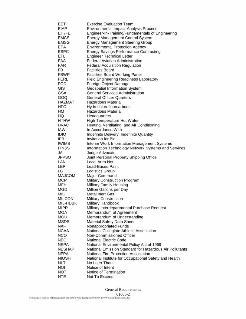
EET Exercise Evaluation Team EIAP Environmental Impact Analysis Process EIT/FE Engineer-In-Training/Fundamentals of Engineering EMCS Energy Management Control System EMSG Energy Management Steering Group EPA Environmental Protection Agency ESPC Energy Savings Performance Contracting ETL Engineer Technical Letter FAA Federal Aviation Administration FAR Federal Acquisition Regulation FB Facilities Board FBWP Facilities Board Working Panel FERL Field Engineering Readiness Laboratory FOD Foreign Object Damage GIS Geospatial Information System GSA General Services Administration GOQ General Officer Quarters HAZMAT Hazardous Material HFC Hydrochlorofluorcarbons HM Hazardous Material HQ Headquarters HTHW High Temperature Hot Water HVAC Heating, Ventilating, and Air Conditioning IAW In Accordance With IDIQ Indefinite Delivery, Indefinite Quantity IFB Invitation for Bid IWIMS Interim Work Information Management Systems ITNSS Information Technology Network Systems and Services JA Judge Advocate JPPSO Joint Personal Property Shipping Office LAN Local Area Net LBP Lead-Based Paint LG Logistics Group MAJCOM Major Command MCP Military Construction Program MFH Military Family Housing MGD Million Gallons per Day MIG Metal Inert Gas MILCON Military Construction MIL-HDBK Military Handbook MIPR Military Interdepartmental Purchase Request MOA Memorandum of Agreement MOU Memorandum of Understanding MSDS Material Safety Data Sheet NAF Nonappropriated Funds NCAA National Collegiate Athletic Association NCO Non-Commissioned Officer NEC National Electric Code NEPA National Environmental Policy Act of 1969 NESHAP National Emission Standard for Hazardous Air Pollutants NFPA National Fire Protection Association NIOSH National Institute for Occupational Safety and Health NLT No Later Than NOI Notice of Intent NOT Notice of Termination NTE Not To Exceed

General Requirements 01000-3
C:\Users\Basco Colorado 001\Documents\15-006 USAFA Water Line\Specs\DIVISION 1\01000 General Requirements.doc
NPDES National Pollutant Discharge Elimination System O&M Operations and Maintenance ODS Ozone Depleting Substance OG Operations Group OSHA Occupational Safety and Health Administration Para Paragraph PC Personnel Computer PCB Polychlorinated Biphenyls PCI Pavement Condition Index PCMS Project by Contract Management System PDC Programming, Design, and Construction PE Professional Engineer POC Point of Contact POL Petroleum, Oils, and Lubricants POM Program Objective Memorandum PSI Per Square Inch PWS Performance Work Statement QAE Quality Assurance Evaluator QAP Quality Assurance Plan QC Quality Control QCI Quality Control Inspector QCP Quality Control Plan RA Registered Architect RAC Risk Assessment Code RAMP Requirements and Management Plan RFI Request for Information RFP Request for Proposal RWP Recurring Work Program SABER Simplified Acquisition of Base Engineer Requirements SBA Small Business Administration SF Standard Form SOQ Senior Officer Quarters SOW Statement of Work TDY Temporary Duty TIG Tungsten Inert Gas TLF Temporary Lodging Facilities U.S. United States UPC Uniform Plumbing Code USAFA United States Air Force Academy USAFAI United States Air Force Academy Instruction USAF United States Air Force VOQ Visiting Officer Quarters VIPs Very Important Persons VOQ Visiting Officer Quarters WIMS Work Information Management System WRRB Work Request Review Board
1.3 BASE ACCESS
A. Access Procedures
1. The Contractor shall provide Contracting Officer with a form USAFA IMT 111, Application for Personnel and Vehicle Passes to work under Air Force Contract. Each individual requiring access, shall fill out this form, with employer signing line 1.14. Each individual must not sign 1.13 until in the presence of officer approving the application. The Contractor shall allow ten working days for the

General Requirements 01000-4
C:\Users\Basco Colorado 001\Documents\15-006 USAFA Water Line\Specs\DIVISION 1\01000 General Requirements.doc
Installation to process passes for individuals. The Government reserves the right to deny access to any questionable individuals. Revisions to the Entry Authorization List shall be provided to the Contracting Officer as names of individuals are added or deleted from the list. Vehicles and attendees are subject to search at the discretion of the Government. The Contractor shall anticipate delays during the inspection process as well as delays due to vehicle queues. These procedures will be discussed further at the pre-construction meeting.
B. Heightened Alert Conditions
1. Conditions caused by Force Majeure (acts of war, terrorism, nature, etc.) shall be addressed via contract time extension at no cost only. The Contractor shall anticipate that in the event of heightened alert, access to the USAF Academy may be denied for approximately three to five days. The Contractor shall also anticipate that during periods of heightened alert, time required to access the USAF Academy may increase threefold for a period of seven days.
1.4 ACADEMY WORK SCHEDULING
A. The Contractor's working hours shall be between 7:00 a.m. and 5:00 p.m., with no work on weekends or the 10 Federal holidays unless allowed by the Contracting Officer (New Year’s Day, Martin Luther King Day, President’s Day, Memorial Day, Independence Day, Labor Day, Columbus Day, Veteran’s Day, Thanksgiving, and Christmas). Permission in writing to work at times other than those stated above must be obtained from the Contracting Officer at least 5 working days in advance.
B. Special Activities, Interruptions, and Delays:
1. The Contractor may be required to temporarily stop work for operational requirements, special events, installation exercises, or while Distinguished Visitor (DV) familiarization visits/tours are conducted. Particular interruptions and work stoppage is to be expected during the weeks of Graduation (late May / early June), Parent’s Weekend (usually in conjunction with Labor Day), and Corona Conference (in the Fall). Official late reporting and snow cals will affect the Contractor’s work periods. The Contractor must make allowances for these events and resulting lost time will not be reimbursable. Notification to the Contactor shall be provided by the Contracting Officer. Work may be allowed in certain areas during these events. Check with the Contracting Officer.
2. For these activities when work may be restricted, the Contractor shall have the areas cleaned, equipment and material organized as directed by the Contracting Officer.
1.5 CONTRACTOR STORAGE AREA REQUIREMENTS
A. The following Contractor’s Storage Area Requirements will be applicable for the project referenced above. The purpose of these requirements is to provide uniformity to the USAF Academy (USAFA) Contractor Storage Areas. Both the location and the dimensions will be site verified by the Contractor and the Contracting Officer’s Technical Representative.
B. FENCING: Install fencing around the perimeter of the storage area. The fencing shall be six feet high. Posts shall be placed at 8 foot on center or closer where required. An
General Requirements 01000-5
C:\Users\Basco Colorado 001\Documents\15-006 USAFA Water Line\Specs\DIVISION 1\01000 General Requirements.doc
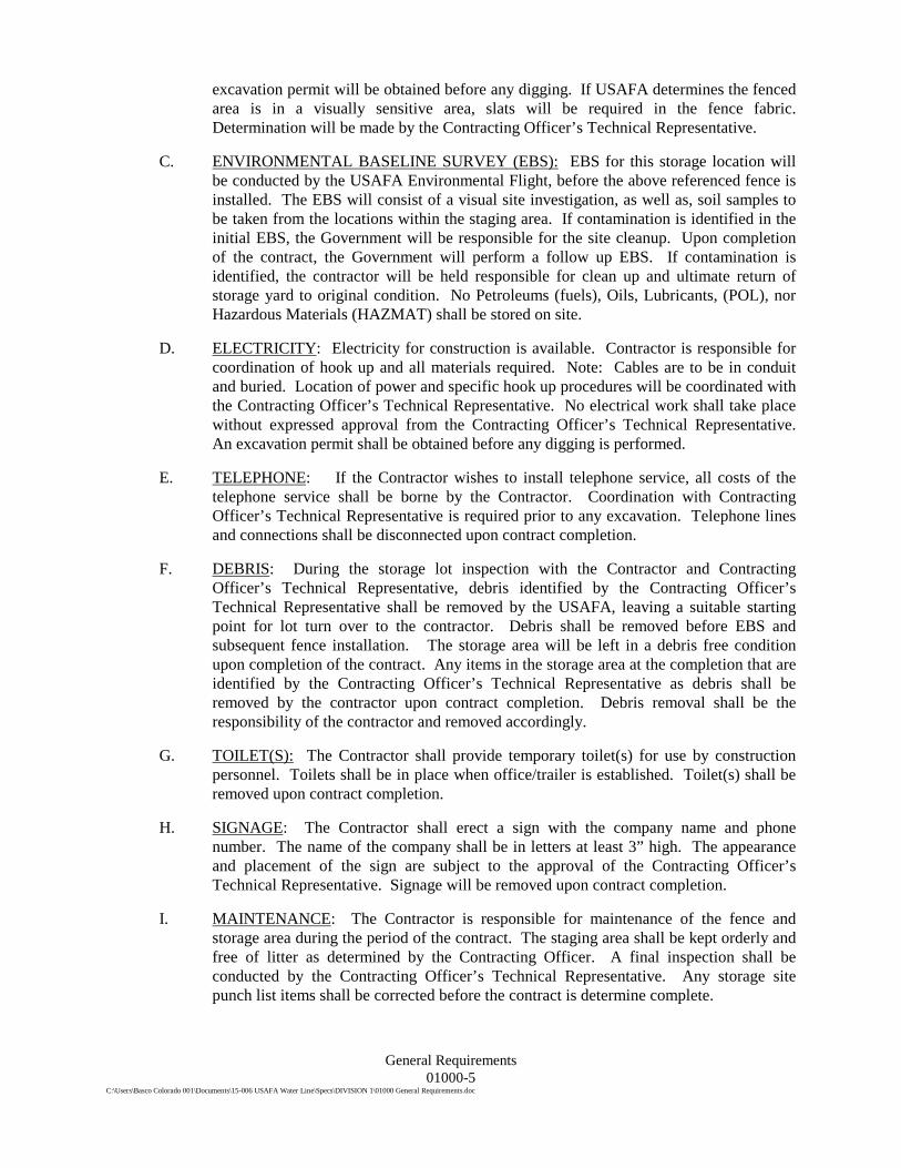
excavation permit will be obtained before any digging. If USAFA determines the fenced area is in a visually sensitive area, slats will be required in the fence fabric. Determination will be made by the Contracting Officer’s Technical Representative.
C. ENVIRONMENTAL BASELINE SURVEY (EBS): EBS for this storage location will be conducted by the USAFA Environmental Flight, before the above referenced fence is installed. The EBS will consist of a visual site investigation, as well as, soil samples to be taken from the locations within the staging area. If contamination is identified in the initial EBS, the Government will be responsible for the site cleanup. Upon completion of the contract, the Government will perform a follow up EBS. If contamination is identified, the contractor will be held responsible for clean up and ultimate return of storage yard to original condition. No Petroleums (fuels), Oils, Lubricants, (POL), nor Hazardous Materials (HAZMAT) shall be stored on site.
D. ELECTRICITY: Electricity for construction is available. Contractor is responsible for coordination of hook up and all materials required. Note: Cables are to be in conduit and buried. Location of power and specific hook up procedures will be coordinated with the Contracting Officer’s Technical Representative. No electrical work shall take place without expressed approval from the Contracting Officer’s Technical Representative. An excavation permit shall be obtained before any digging is performed.
E. TELEPHONE: If the Contractor wishes to install telephone service, all costs of the telephone service shall be borne by the Contractor. Coordination with Contracting Officer’s Technical Representative is required prior to any excavation. Telephone lines and connections shall be disconnected upon contract completion.
F. DEBRIS: During the storage lot inspection with the Contractor and Contracting Officer’s Technical Representative, debris identified by the Contracting Officer’s Technical Representative shall be removed by the USAFA, leaving a suitable starting point for lot turn over to the contractor. Debris shall be removed before EBS and subsequent fence installation. The storage area will be left in a debris free condition upon completion of the contract. Any items in the storage area at the completion that are identified by the Contracting Officer’s Technical Representative as debris shall be removed by the contractor upon contract completion. Debris removal shall be the responsibility of the contractor and removed accordingly.
G. TOILET(S): The Contractor shall provide temporary toilet(s) for use by construction personnel. Toilets shall be in place when office/trailer is established. Toilet(s) shall be removed upon contract completion.
H. SIGNAGE: The Contractor shall erect a sign with the company name and phone number. The name of the company shall be in letters at least 3” high. The appearance and placement of the sign are subject to the approval of the Contracting Officer’s Technical Representative. Signage will be removed upon contract completion.
I. MAINTENANCE: The Contractor is responsible for maintenance of the fence and storage area during the period of the contract. The staging area shall be kept orderly and free of litter as determined by the Contracting Officer. A final inspection shall be conducted by the Contracting Officer’s Technical Representative. Any storage site punch list items shall be corrected before the contract is determine complete.

General Requirements 01000-6
C:\Users\Basco Colorado 001\Documents\15-006 USAFA Water Line\Specs\DIVISION 1\01000 General Requirements.doc
J. TREES: Trees (> 4” diameter) within the site shall be left in place, and care taken not to compact ground around them. Smaller tree removal shall be the responsibility of the USAFA. Coordination with the Contracting Officer’s Technical Representative is required before fence or utility installation.
K. CONSTRUCTION TRAILER: Construction trailers must comply with USAFA color scheme. This is a tan scheme. Their location at a project or within a storage yard must be approved by the Contracting Officer’s Technical Representative.
1.6 CONTRACTOR CONSTRUCTION SIGNAGE
A. All construction projects shall have a sign telling the general public of the intent of the project and other pertinent project information. See the example shown on the next page.

General Requirements 01000-7
C:\Users\Basco Colorado 001\Documents\15-006 USAFA Water Line\Specs\DIVISION 1\01000 General Requirements.doc
Sign Standards Dimensions: 8’ X 4’ Back Ground: White Text Color: Black Bird Height: 21.5” Text size: “Please pardon the…” Statement: 4” USAFA Civil Engineer: 2.5” Project Title Info: 3” Investment/Completion Info: 2” Project Specifics: 2”
“Please pardon the inconvenience as we build for
future generations of Air Force leaders.”
USAFA Civil Engineer
FY0X Project Title Investment: $X.X million Estimated Completion: Summer 200X
CUSTOMER: List Customer Here ADMINISTRATIVE AGENT: 10MSG/LGCA ARCHITECT: List Name Here ENGINEER: List Name Here CONTRACTOR: List Name Here

General Requirements 01000-8
C:\Users\Basco Colorado 001\Documents\15-006 USAFA Water Line\Specs\DIVISION 1\01000 General Requirements.doc
1.7 UTILITIES
A. Reasonable amounts of utilities necessary for the project, such as water and electricity, will be provided to the Contractor at no additional cost, as determined by the Contracting Officer. The Contractor shall be responsible for installing and maintaining temporary lines and properly removing them after work is complete.
B. Fire Hydrant Connections: Only compatible adapters shall be utilized for hydrant connections. A gate valve shall be provided and installed by the Contractor between the hydrant and supply hoses to control flow. Connection shall include backflow protection. Temporary connections to fire hydrants shall be disconnected at the end of each working day. No quick closing valves such as plug or butterfly valves will be used. Notify the Fire Department (333-4433) prior to connection.
C. Removal: Prior to final acceptance, all temporary cords, lines or other equipment shall be removed and the existing outlets and lines restored to the conditions existing prior to the start of construction.
D. Utility Outages: Any proposed utility outages necessitated by the work shall be requested in writing to the Contracting Officer or Contracting Officer’s Technical Representative at least fifteen (15) working days prior to the proposed outage. The request shall stipulate the specific utility systems and circuits to be affected, the location of the work, the time at which the shutdown will occur, and the duration of the outage for each system. Outages shall be kept to a minimum both in number and in duration. Where multiple outages are required, as many outages as can be accurately scheduled shall be submitted as a group.
1.8 OUTAGE WORK SEQUENCE REQUIREMENT
A. Critical to the success of this project will be the phasing and sequencing of the work to minimize down time and inconvenience to the facility occupants and base personnel.
B. The Contractor shall develop and submit to the Contracting Officer’s Technical Representative for approval, any outage or traffic closure plans/schedules fifteen (15) working days prior to commencing of work. The plan shall include details of the actions to be taken during the outage or closure, additional crews and extended work hours required, how and where temporary back-up power will be provided, contingency plans if the proposed actions are not completed as scheduled, the estimated dates and times of the outage or closure, and which sections of facilities will affected. Changes to outage or closure plans as shown on drawings or in specs should be requested 21 days in advance.
1.9 CONSTRUCTION MATERIALS
A. The USAF Academy is committed that no asbestos containing materials (ACM) will be introduced onto the base. A submittal memorandum will be required from the Contractor documenting that no materials brought on base are ACM.
1.10 DEFERRAL OF RECURRING WORK ON EQUIPMENT
A. Maintenance Engineering, 10CES/CEOE, must be made aware of any equipment that is taken out of service for any period of time during construction, and also if the equipment

General Requirements 01000-9
C:\Users\Basco Colorado 001\Documents\15-006 USAFA Water Line\Specs\DIVISION 1\01000 General Requirements.doc
is removed as part of the project. The reason for this is so the Recurring Work Program (RWP) can be modified to account for the equipment being down or removed.
B. Fifteen (15) working days prior prior to any equipment being taken out of service, the following information must be sent to Maintenance Engineering, 10CES/CEOE:
1. Project Number 2. Facility 3. Construction Inspector Name 4. Contractor 5. Nomenclature / Description of Equipment Item 6. Location within Facility 7. Manufacturer 8. Model Name 9. Model Number 10. Serial Number 11. Capacity / Size 12. “Out of Service” Date 13. Mark as “Deferred” if replacing or “Removed” if no replacement.
PART 2 PRODUCTS
NOT USED.
PART 3 EXECUTION
NOT USED.
END OF SECTION
Summary of Work 01110-1
C:\Users\Basco Colorado 001\Documents\15-006 USAFA Water Line\Specs\DIVISION 1\01110 Summary of Work.doc
SECTION 01110 SUMMARY OF WORK
PART 1 GENERAL
1.1 SECTION INCLUDES
A. Project description, work summary, and work by Owner.
1.2 BACKGROUND
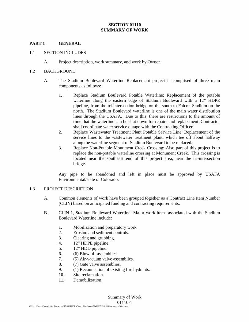
A. The Stadium Boulevard Waterline Replacement project is comprised of three main components as follows:
1. Replace Stadium Boulevard Potable Waterline: Replacement of the potable waterline along the eastern edge of Stadium Boulevard with a 12” HDPE pipeline, from the tri-intersection bridge on the south to Falcon Stadium on the north. The Stadium Boulevard waterline is one of the main water distribution lines through the USAFA. Due to this, there are restrictions to the amount of time that the waterline can be shut down for repairs and replacement. Contractor shall coordinate water service outage with the Contracting Officer.
2. Replace Wastewater Treatment Plant Potable Service Line: Replacement of the service lines to the wastewater treatment plant, which tee off about halfway along the waterline segment of Stadium Boulevard to be replaced.
3. Replace Non-Potable Monument Creek Crossing: Also part of this project is to replace the non-potable waterline crossing at Monument Creek. This crossing is located near the southeast end of this project area, near the tri-intersection bridge.
Any pipe to be abandoned and left in place must be approved by USAFA Environmental/state of Colorado.
1.3 PROJECT DESCRIPTION
A. Common elements of work have been grouped together as a Contract Line Item Number (CLIN) based on anticipated funding and contracting requirements.
B. CLIN 1, Stadium Boulevard Waterline: Major work items associated with the Stadium Boulevard Waterline include:
1. Mobilization and preparatory work. 2. Erosion and sediment controls. 3. Clearing and grubbing. 4. 12” HDPE pipeline. 5. 12” HDD pipeline. 6. (6) Blow off assemblies. 7. (5) Air-vacuum valve assemblies. 8. (7) Gate valve assemblies. 9. (1) Reconnection of existing fire hydrants. 10. Site reclamation. 11. Demobilization.

Summary of Work 01110-2
C:\Users\Basco Colorado 001\Documents\15-006 USAFA Water Line\Specs\DIVISION 1\01110 Summary of Work.doc
C. CLIN 2, Wastewater Treatment Plant Service: Major work items associated with the Wastewater Treatment Plant Service include:
1. Mobilization and preparatory work. 2. Erosion and sediment controls. 3. Clearing and grubbing. 4. 10” HDPE pipeline. 5. 10” HDD pipeline. 6. (1) Blow off assembly. 7. (3) Gate valve assemblies. 8. Site reclamation. 9. Demobilization.
D. CLIN 3, Non-Potable Waterline Crossing at Monument Creek: Major work items associated with the Non-Potable Waterline include:
1. Mobilization and preparatory work. 2. Erosion and sediment controls. 3. Clearing and grubbing. 4. 6” HDPE pipeline. 5. 6” HDD pipeline. 6. (1) Air-vacuum valve assemblies. 7. (2) Gate valve assemblies. 8. Site reclamation. 9. Demobilization.
1.4 OWNER OCCUPANCY
A. The Owner will occupy the premises full time during the period of construction to conduct normal operations.
B. Cooperate with Owner to minimize conflicts, and to facilitate Owner’s operations.
PART 2 PRODUCTS
NOT USED.
PART 3 EXECUTION
NOT USED.
END OF SECTION

Contractor Work Plan 01120-1
C:\Users\Basco Colorado 001\Documents\15-006 USAFA Water Line\Specs\DIVISION 1\01120 Contractor Work Plan.doc
SECTION 01120 CONTRACTOR WORK PLAN
PART 1 GENERAL
1.1 SUMMARY
A. This section covers the Contractor Work Plan.
1.2 SUBMITTALS
A. Submit in accordance with Section 01330 - Submittals.
B. Prepare and submit a project-specific Work Plan to the Contracting Officer for approval within 14 days after Award. Include the following topics in the Work Plan:
1. Construction implementation plan to include work approach, equipment to be used for each item of construction, methods, and management.
2. Key personnel names and qualifications, list of subcontractors, including an organizational chart and project directory with contact information.
3. Health and Safety Plan. See Section 01145: Health and Safety. 4. Environmental Protection. See Section 01350: USAFA Environmental
Standards. 5. Spill prevention and control procedures. See Section 01350: USAFA
Environmental Standards. 6. Fire prevention and protection. See Section 01350: USAFA Environmental
Standards. 7. Dust control. See Section 01350: USAFA Environmental Standards. (BMPs to
be used). 8. Construction sequence and schedule. See Section 01320: Construction Progress
Schedule. 9. Disposal Plan. 10. Construction Quality Control Plan (CQCP). See Section 01450: Quality Control. 11. Other applicable items to describe work approach.
1.3 WORK PLAN REQUIREMENTS
A. The Work Plan shall be carefully thought out, prepared in accordance with all applicable Federal, state, and local laws and regulations, these specifications, and good engineering and construction practices. The Work Plan shall include a complete discussion of conformance with applicable laws, regulations, guidelines, and other applicable procedures, and shall be approved by the Contracting Officer before beginning field activities.
B. The Work Plan shall be developed in accordance with the requirement of the individual specifications indicated and other requirements in this specification.

Contractor Work Plan 01120-2
C:\Users\Basco Colorado 001\Documents\15-006 USAFA Water Line\Specs\DIVISION 1\01120 Contractor Work Plan.doc
PART 2 PRODUCTS
NOT USED.
PART 3 EXECUTION
NOT USED.
END OF SECTION

Health and Safety 01145-1
C:\Users\Basco Colorado 001\Documents\15-006 USAFA Water Line\Specs\DIVISION 1\01145 Health and Safety.DOC
SECTION 01145 HEALTH AND SAFETY
PART 1 GENERAL
1.1 REFERENCES
A. Williams - Steiger Occupation Safety and Health Act of 1970.
B. All other applicable Federal, State, and Local Safety and Health requirements.
1.2 CONTRACTOR'S RESPONSIBILITY
A. Provide and implement a health and safety plan that conforms to all applicable regulations.
B. The plan shall include the possibility of encountering hazardous or controlled waste at the site, worker protection, actions to be taken, and responsible parties for managing such waste streams.
1.3 OWNER AND ENGINEER'S RESPONSIBILITY
A. Owner and Engineer will have no responsibility for enforcing the Contractor's health and safety program.
1.4 SUBMITTALS
A. Contractor's Project Health and Safety Plan, submitted in accordance with the General Conditions. The plan is for informational purposes only.
PART 2 PRODUCTS
NOT USED.
PART 3 EXECUTION
NOT USED.
END OF SECTION

Existing Utility Coordination 01180-1
C:\Users\Basco Colorado 001\Documents\15-006 USAFA Water Line\Specs\DIVISION 1\01180 Existing Utility Coordination.doc
SECTION 01180 EXISTING UTILITY COORDINATION
PART 1 GENERAL
1.1 SUMMARY OF WORK
A. This section includes coordination requirements for existing utilities including notification of and coordination with utility owners, and existing protection, removal, and relocation requirements.
B. Contractor is responsible for planning, scheduling, and access coordination with Utility Provider for construction of temporary service routes, cut-overs, demo work and final new services as shown on the Drawings and as necessary to complete all required construction elements. Contractor is responsible for all costs associated with relocation service applications, permits, inspections and testing as may be required for final service.
1.2 REFERENCES
A. Not Used.
1.3 SUBMITTALS
A. Submit in accordance with Section 01330: Submittals.
B. Authorizations from utility owners:
1. Utility relocation authorizations. 2. Repair authorizations
C. Certifications: Certifications that utility relocations have been coordinated with and approved by the utility companies. Certification shall include a narrative description of the utility’s requirements and points of connection and names and telephone numbers for contacts at the utilities.
1.4 CONTRACTOR QUALITY CONTROL
A. The Contractor is required to have available a qualified utility location company, capable personnel, and locator equipment to identify underground utilities in the interest of avoiding unnecessary damage, maintenance costs, and to insure continuity of utility service.
B. Cooperate with utility owners to aid in locations and maintenance of existing utilities.
1.5 LEGAL REQUIREMENTS-UNDERGROUND FACILITIES
A. Before commencing excavation in any area, comply with the provisions of any applicable laws relating to or governing the identification, location, marking, and responsibility for protecting and repairing of underground and overhead utilities.
B. Whenever there may be a conflict between the provisions of any law and the provisions of these specifications, the provisions of law shall control.

Existing Utility Coordination 01180-2
C:\Users\Basco Colorado 001\Documents\15-006 USAFA Water Line\Specs\DIVISION 1\01180 Existing Utility Coordination.doc
1.6 DEFINITIONS
A. Utility means any facility or item for use in connection with the storage or conveyance of water, sewage, monitoring well, electronic, telephonic or telegraphic communication, cablevision, electric energy, petroleum products, gas, gaseous vapors, hazardous liquids, or other substances and including, but not limited to pipes, sewers, conduits, cables, valves, lines, wires, manholes, and attachments.
1.7 IDENTIFICATION
A. Locate all underground utilities whether or not identified on the Drawings.
B. The Contracting Officer, under this Contract, does not warrant the location of underground utilities.
1.8 NOTIFICATION
A. It is the responsibility of the Contractor to give notice to the Contracting Officer of any utilities known or suspected to be within the area of any proposed excavation or construction activities.
B. The Contractor is responsible to have the locations of underground utilities marked by the utility owners prior to beginning excavation.
C. The Contractor is responsible for determining the extent of any hazard created by electrical power in all areas and shall follow procedures during construction as required by law and regulation. Prior to construction, the Contractor shall meet with utility owners and determine the extent of hazards and remedial measures and shall take whatever precautions may be required.
D. Contractor shall contact 10CS 333-4421, before removing or cutting any communications cable.
1.9 RELOCATION
A. Per UFC 3-580-01, Telecommunications design must be performed and stamped by a Registered Communications Distribution Designer (RCDD) for all projects.
B. During construction, support and protect from injury as necessary all existing utilities in the vicinity of the Work whether shown on the Drawings or not. Contractor is responsible for all damage done to such existing utilities.
C. Contractor may relocate utilities if authorized in writing by the utility owner.
D. Notify owners of existing utilities which are within 15 feet of proposed trench excavations, prior to proceeding with such excavations, or in accordance with utility requirements if they are more stringent.
E. When Contractor determines that an existing utility must be relocated, notify the utility owner in sufficient time prior to approaching the utility to avoid delay of the Work.
F. Should any utility be damaged by Contractor's operations, immediately notify the owner of such utility. Unless authorized in writing by such utility, do not attempt to make repairs. Provide the Contracting Officer a copy of any written authorization given to Contractor to make repairs.

Existing Utility Coordination 01180-3
C:\Users\Basco Colorado 001\Documents\15-006 USAFA Water Line\Specs\DIVISION 1\01180 Existing Utility Coordination.doc
G. Reconstruct all existing utilities exposed during construction to the specifications required by the utility owner.
1.10 MINIMUM SEPARATION
A. All relocated or newly installed utilities shall be installed with the following minimum clearances from any other water, gas or electric utility:
1. Horizontal clearance: 10 feet 2. Vertical clearance: 1.5 feet
B. Any variations from these clearances require approval by the Contracting Officer.
C. Like utilities may be installed with lesser clearances as shown on the Drawings or approved by the Contracting Officer.
1.11 ELECTRICAL TRANSMISSION AND SERVICE LINES
A. The Contractor is responsible for observing and investigating the presence of any electrical transmission lines which might impinge on his work whether overhead or underground. The Contractor shall consult with and utilize information provided by utility owners to determine the extent of any hazards and remedial measures required, and follow appropriate safety procedures.
1.12 ABOVE GROUND UTILITIES
A. Existing above ground utilities, whether shown on the Drawings or not, shall be maintained, relocated, rerouted, removed and restored by the Contractor in order to complete the Work. All Work with existing utilities shall be completed in a manner satisfactory to the Contracting Officer and operators of the utility.
PART 2 PART 2 – PRODUCTS
NOT USED
PART 3 PART 3 – EXECUTION
NOT USED
END OF SECTION

Price and Payment Procedures 01200-1 C:\Users\Basco Colorado 001\Documents\15-006 USAFA Water Line\Specs\DIVISION 1\01200 Price and Payment Procedures.doc 9/27/10
SECTION 01200 PRICE AND PAYMENT PROCEDURES
PART 1 GENERAL
1.1 SECTION INCLUDES
A. Measurement and payment criteria applicable to work performed under a unit price payment method.
B. Measurement and payment criteria applicable to work performed under a lump sum payment method.
C. List of unit price and lump sum pay items.
D. Schedule of value requirements for lump sum pay items.
E. Defect assessment and non-payment for rejected work.
1.2 AUTHORITY
A. Measurement methods delineated in the individual Specification Sections are intended to complement the criteria of this Section. In the event of conflict, the requirements of the individual Specification Section shall govern.
B. Take all measurements and compute quantities for unit price pay items. The Contracting Officer will verify measurements and quantities of work performed by the Contractor for payment purposes.
C. Assist the Contracting Officer in the taking of measurements by providing necessary equipment, workers, and survey personnel as required.
1.3 QUANTITIES OF UNIT PRICE ITEMS
A. Quantities indicated in the Bid Form are for bidding and contract purposes only. Actual quantities and measurements supplied or placed in the work and verified by the Contracting Officer shall determine payment.
1.4 MEASUREMENT OF QUANTITIES FOR UNIT PRICE ITEMS
A. Measurement Devices:
1. Weigh scales: inspected, tested, and certified by the appropriate Colorado Weights and Measures Division within the past year.
2. Platform scales: of sufficient size and capacity to accommodate the conveying vehicle.
3. Metering devices: inspected, tested, and certified by the appropriate Colorado Weights and Measures Division within the past year.
B. Measurement by volume: Measured by cubic dimension using mean length, width, and height or thickness.
C. Excavation quantities will be based on the calculated volume between the baseline survey, as defined in Section 01720 – Layout of Work and Surveying and the excavation limits shown on the Drawings or described in these Specifications, or to the most

Price and Payment Procedures 01200-2 C:\Users\Basco Colorado 001\Documents\15-006 USAFA Water Line\Specs\DIVISION 1\01200 Price and Payment Procedures.doc 9/27/10
practicable lines, grades and dimensions as prescribed by the Contracting Officer, and will include only material that is actually removed within the prescribed pay lines.
D. Fill quantities will be based on the calculated volume between the approved excavation limits or the approved base surface and the fill limits shown on the Drawings or described in these Specifications, or to the most practicable lines, grades and dimensions as prescribed by the Contracting Officer, and will include only material that is actually placed within the described pay lines.
E. Compute excavation and fill quantities in accordance with the requirements of Section 01720 – Layout of Work and Surveying.
F. Where concrete for structures is to be placed directly upon or against the excavations and the character of the material cut into is such that the material cannot be trimmed efficiently to accurate dimensions by ordinary excavation finishing methods, as determined by the Contracting Officer, measurement for payment thereof will be made to the prescribed average dimension lines. The prescribed average dimension lines shall be considered as 6 inches outside the neat lines of the concrete for the purposes of measurement, for payment.
G. Measurement, for payment, of excavations upon or against which concrete is not required to be placed will be limited to the neat lines shown on the Drawings, to the most practicable lines, grades, and dimensions as established by the Contracting Officer.
H. Measurement by area: Measured by square dimension using mean length and width or radius. Items which are measured by the acre, such as revegetation, shall be measured horizontally.
I. Linear measurement: Measured by linear dimension, at the item centerline or mean chord. Items which are measured by the lineal foot, such as pipes, fence, etc., shall be measured parallel to the base or foundations upon which the items are placed, unless otherwise specified or shown on the Drawings.
J. Stipulated sum/price measurement: Items measured by weight, volume, area, or linear means or combination, as appropriate, as completed items or units of the Work.
K. Lump sum items will not be measured for payment. However, measurements may be made to monitor work progress.
1.5 ALLOWANCE MEASUREMENT:
A. Measurement of allowance-based items shall be on the basis of allowable documented costs, as specified herein, for labor, equipment, materials and services, and subcontracts as submitted by the Contractor in the form of time-cards, and invoices.
B. Payment for allowance item shall only include markups in the amount allowed by the Contract Documents for Time and Materials work.
C. In the event that the allowance amount is not fully expended, the remainder will accrue to the Owner’s account and shall not be paid to the Contractor.
D. Payment under the allowance item for labor, equipment, materials and services, and subcontracts will be in accordance with the following:

Price and Payment Procedures 01200-3 C:\Users\Basco Colorado 001\Documents\15-006 USAFA Water Line\Specs\DIVISION 1\01200 Price and Payment Procedures.doc 9/27/10
1. Cost of labor for workers directly engaged in the performance of the Work. Cost of labor shall include actual wages paid including employer payments to or on behalf of the workers for health and welfare, pension, vacation, and similar purposes plus payments imposed on payroll amounts by applicable laws and regulations plus subsistence and travel allowance payments to worker.
2. Cost of material shall include sales tax, freight, and delivery charges. 3. Cost of equipment actually engaged in the performance of the Work. Equipment
rates shall be the lesser of the actual rental rates or those listed for such equipment in a Force Account Schedule to be submitted by the Contractor and approved by the Contracting Officer. No payment will be made for equipment on standby or idle time. Payment for equipment will only be made for actual time of use as verified by the Contracting Officer. The equipment rental rates shall include the cost of fuel, oil, lubrication, supplies, small tools, necessary attachments, repair and maintenance of any kind, depreciation. storage, insurance, and all incidentals.
1.6 PAYMENT
A. Payment includes: Full compensation for furnishing all required labor, materials, products, tools, equipment, plant, transportation, services, incidentals; erection, application or installation of an item of the work, and all other costs of whatsoever nature for the items of work complete, will be included in the various bid items; overhead and profit.
B. Contractor shall submit a Schedule of Values for all lump sum bid items listed in the Bid Schedule within 30 days of the Notice to Proceed. The Schedule of Values will be used to help assess the intermediate value of work completed for the purpose of making progress payments
C. Payment for unit price items will be made on the basis of the actual measurements and quantities accepted by the Contracting Officer multiplied by the unit price.
D. Payment for lump sum price items will be made on the basis of the contract lump sum prices in the Bid Form. If the Contractor requests progress payments for lump sum items, such progress payments will be made in accordance with a detailed program of payment apportioning in the schedule of values, prepared by the Contractor and submitted to the Contracting Officer for approval.
1.7 DEFINITION OF BID ITEMS
A. Bid items are separated per the bid schedule for each Contract Line Item Number (CLIN).
B. CLIN 1 – Stadium Boulevard Waterline
1. Mobilization, Demobilization, and Preparatory Work (Lump Sum Item)
a. This item includes the mobilization of personnel, equipment and temporary construction facilities to the project site and their subsequent removal; providing temporary utilities; safety fence; traffic control signage and barricades; and other miscellaneous items required to begin construction and closeout the Contract. The cost of all work specified in Division 1 - General Requirements, unless specifically covered in other bid

Price and Payment Procedures 01200-4 C:\Users\Basco Colorado 001\Documents\15-006 USAFA Water Line\Specs\DIVISION 1\01200 Price and Payment Procedures.doc 9/27/10
items, will not be paid separately, but shall be included in the lump sum price bid in the Schedule for Mobilization and Preparatory Work.
b. Measurement: This item will not be measured for payment. c. Payment will be made for Mobilization and Preparatory Work as
follows, subject to acceptable construction progress:
1) Thirty percent of the bid price for this Bid Item with the first monthly progress payment.
2) Twenty-five percent of the bid price for this Bid Item with the second monthly progress payment provided, in the Owner’s assessment, the work is progressing reasonably towards scheduled completion.
3) The remainder shall be equally prorated over each remaining payment request for the balance of the construction schedule.
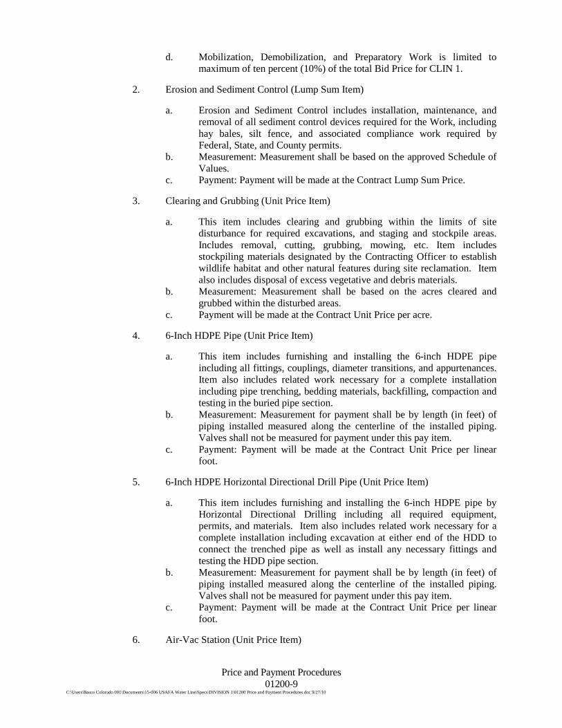
d. Mobilization, Demobilization, and Preparatory Work is limited to maximum of ten percent (10%) of the total Bid Price for CLIN 1.
2. Erosion and Sediment Control (Lump Sum Item)
a. Erosion and Sediment Control includes installation, maintenance, and removal of all sediment control devices required for the Work, including hay bales, silt fence, and associated compliance work required by Federal, State, and County permits.
b. Measurement: Measurement shall be based on the approved Schedule of Values.
c. Payment: Payment will be made at the Contract Lump Sum Price.
3. Clearing and Grubbing (Unit Price Item)
a. This item includes clearing and grubbing within the limits of site disturbance for required excavations, and staging and stockpile areas. Includes removal, cutting, grubbing, mowing, etc. Item includes stockpiling materials designated by the Contracting Officer to establish wildlife habitat and other natural features during site reclamation. Item also includes disposal of excess vegetative and debris materials.
b. Measurement: Measurement shall be based on the acres cleared and grubbed within the disturbed areas.
c. Payment will be made at the Contract Unit Price per acre.
4. 12-Inch HDPE Pipe (Unit Price Item)
a. This item includes furnishing and installing the 12-inch HDPE pipe including all fittings, couplings, diameter transitions, tracer wire, and appurtenances. Item also includes related work necessary for a complete installation including pipe trenching, bedding materials, backfilling, compaction and testing in the buried pipe section.
b. Measurement: Measurement for payment shall be by length (in feet) of piping installed measured along the centerline of the installed piping. Valves shall not be measured for payment under this pay item.
c. Payment: Payment will be made at the Contract Unit Price per linear foot.

Price and Payment Procedures 01200-5 C:\Users\Basco Colorado 001\Documents\15-006 USAFA Water Line\Specs\DIVISION 1\01200 Price and Payment Procedures.doc 9/27/10
5. 12-Inch HDPE Horizontal Directional Drill Pipe (Unit Price Item)
a. This item includes furnishing and installing the 12-inch HDPE pipe by Horizontal Directional Drilling including all required equipment, permits, and materials. Item also includes related work necessary for a complete installation including excavation at either end of the HDD to connect the trenched pipe as well as install any necessary fittings and testing the HDD pipe section.
b. Measurement: Measurement for payment shall be by length (in feet) of piping installed measured along the centerline of the installed piping. Valves shall not be measured for payment under this pay item.
c. Payment: Payment will be made at the Contract Unit Price per linear foot.
6. Blow-Off Station (Unit Price Item)
a. This item includes all work associated with furnishing and installing the blow-off station including valving, piping, precast concrete structure, and appurtenances. Item also includes related work necessary for a complete installation including excavation, bedding materials, backfilling, compaction, coatings, and testing on the blow-off station.
b. Measurement: Measurement shall be by each blow-off station installed. c. Payment: Payment will be made at the Contract Unit Price per each.
7. Air-Vac Station (Unit Price Item)
a. This item includes all work associated with furnishing and installing the air-vac station including valving, piping, precast concrete structure, and appurtenances. Item also includes related work necessary for a complete installation including excavation, bedding materials, backfilling, compaction, coatings, and testing on the air-vac station.
b. Measurement: Measurement shall be by each air-vac station installed. c. Payment: Payment will be made at the Contract Unit Price per each.
8. 12-Inch Gate Valve (Unit Price Item)
a. This item includes furnishing, installing, and testing the 12-inch gate valve. This includes the gate stem, flush mounted valve box, and casing for the gate stem.
b. Measurement: Measurement shall be by each gate valve installed. c. Payment: Payment will be made at the Contract Unit Price per each.
9. Reconnection of Existing Fire Hydrants (Unit Price Item)
a. This item includes reconnecting existing fire hydrants to the newly constructed waterline. This includes furnishing and installing additional required piping and appurtenances to complete the fire hydrant assembly and testing the fire hydrant.
b. Measurement: Measurement shall be by each fire hydrant reconnected. c. Payment: Payment will be made at the Contract Unit Price per each.
10. Site Reclamation (Unit Price Item)

Price and Payment Procedures 01200-6 C:\Users\Basco Colorado 001\Documents\15-006 USAFA Water Line\Specs\DIVISION 1\01200 Price and Payment Procedures.doc 9/27/10
a. This item includes procuring, transporting, and placing materials required for site reclamation including soil preparation, seeding, mulching, watering, and maintaining in all disturbed areas. Item also includes hauling topsoil from stockpiles, spreading, and grading topsoil evenly over the areas to be reclaimed.
b. Measurement: Measurement shall be by area (square acres) of areas seeded, measured to the nearest hundredth of an acre.
c. Payment: Payment shall be made at the Contract Unit Price per acre.
11. 12-Inch HDPE Horizontal Directional Drill Pipe 500 ft Allowance (Unit Price Item)
a. This item includes furnishing and installing the 12-inch HDPE pipe by Horizontal Directional Drilling including all required equipment, permits, and materials. Item also includes related work necessary for a complete installation including excavation at either end of the HDD to connect the trenched pipe as well as install any necessary fittings and testing the HDD pipe section.
b. Measurement: Measurement for payment shall be by length (in feet) of piping installed measured along the centerline of the installed piping. Valves shall not be measured for payment under this pay item. Installation will be completed only under the direction of the Contracting Officer in cases where unexpected field conditions, such as trees or other conflicts, require HDD pipeline installation.
c. Payment: Payment will be made at the Contract Unit Price per linear foot.
C. CLIN 2 – Wastewater Treatment Plant Service Waterline
1. Mobilization, Demobilization, and Preparatory Work (Lump Sum Item)
a. This item includes the mobilization of personnel, equipment and temporary construction facilities to the project site and their subsequent removal; providing temporary utilities; safety fence; traffic control signage and barricades; and other miscellaneous items required to begin construction and closeout the Contract. The cost of all work specified in Division 1 - General Requirements, unless specifically covered in other bid items, will not be paid separately, but shall be included in the lump sum price bid in the Schedule for Mobilization and Preparatory Work.
b. Measurement: This item will not be measured for payment. c. Payment will be made for Mobilization and Preparatory Work as
follows, subject to acceptable construction progress:
1) Thirty percent of the bid price for this Bid Item with the first monthly progress payment.
2) Twenty-five percent of the bid price for this Bid Item with the second monthly progress payment provided, in the Owner’s assessment, the work is progressing reasonably towards scheduled completion.
3) The remainder shall be equally prorated over each remaining payment request for the balance of the construction schedule.

Price and Payment Procedures 01200-7 C:\Users\Basco Colorado 001\Documents\15-006 USAFA Water Line\Specs\DIVISION 1\01200 Price and Payment Procedures.doc 9/27/10
d. Mobilization, Demobilization, and Preparatory Work is limited to maximum of ten percent (10%) of the total Bid Price for CLIN 1.
2. Erosion and Sediment Control (Lump Sum Item)
a. Erosion and Sediment Control includes installation, maintenance, and removal of all sediment control devices required for the Work, including hay bales, silt fence, and associated compliance work required by Federal, State, and County permits.
b. Measurement: Measurement shall be based on the approved Schedule of Values.
c. Payment: Payment will be made at the Contract Lump Sum Price.
3. Clearing and Grubbing (Unit Price Item)
a. This item includes clearing and grubbing within the limits of site disturbance for required excavations, and staging and stockpile areas. Includes removal, cutting, grubbing, mowing, etc. Item includes stockpiling materials designated by the Contracting Officer to establish wildlife habitat and other natural features during site reclamation. Item also includes disposal of excess vegetative and debris materials.
b. Measurement: Measurement shall be based on the acres cleared and grubbed within the disturbed areas.
c. Payment will be made at the Contract Unit Price per acre.
4. 10-Inch HDPE Pipe (Unit Price Item)
a. This item includes furnishing and installing the 10-inch HDPE pipe including all fittings, couplings, diameter transitions, and appurtenances. Item also includes related work necessary for a complete installation including pipe trenching, bedding materials, backfilling, compaction and testing in the buried pipe section.
b. Measurement: Measurement for payment shall be by length (in feet) of piping installed measured along the centerline of the installed piping. Valves shall not be measured for payment under this pay item.
c. Payment: Payment will be made at the Contract Unit Price per linear foot.
5. 10-Inch HDPE Horizontal Directional Drill Pipe (Unit Price Item)
a. This item includes furnishing and installing the 10-inch HDPE pipe by Horizontal Directional Drilling including all required equipment, permits, and materials. Item also includes related work necessary for a complete installation including excavation at either end of the HDD to connect the trenched pipe as well as install any necessary fittings and testing the HDD pipe section.
b. Measurement: Measurement for payment shall be by length (in feet) of piping installed measured along the centerline of the installed piping. Valves shall not be measured for payment under this pay item.
c. Payment: Payment will be made at the Contract Unit Price per linear foot.
6. Blow-Off Station (Unit Price Item)

Price and Payment Procedures 01200-8 C:\Users\Basco Colorado 001\Documents\15-006 USAFA Water Line\Specs\DIVISION 1\01200 Price and Payment Procedures.doc 9/27/10
a. This item includes all work associated with furnishing and installing the blow-off station including valving, piping, precast concrete structure, and appurtenances. Item also includes related work necessary for a complete installation including excavation, bedding materials, backfilling, compaction, coatings, and testing on the blow-off station.
b. Measurement: Measurement shall be by each blow-off station installed. c. Payment: Payment will be made at the Contract Unit Price per each.
7. 10-Inch Gate Valve (Unit Price Item)
a. This item includes furnishing, installing, and testing the 10-inch gate valve. This includes the gate stem, flush mounted valve box, and casing for the gate stem.
b. Measurement: Measurement shall be by each gate valve installed. c. Payment: Payment will be made at the Contract Unit Price per each.
8. Site Reclamation (Unit Price Item)
a. This item includes procuring, transporting, and placing materials required for site reclamation including soil preparation, seeding, mulching, watering, and maintaining in all disturbed areas. Item also includes hauling topsoil from stockpiles, spreading, and grading topsoil evenly over the areas to be reclaimed.
b. Measurement: Measurement shall be by area (square acres) of areas seeded, measured to the nearest hundredth of an acre.
c. Payment: Payment shall be made at the Contract Unit Price per acre.
D. CLIN 3 – Non-Potable Waterline Crossing at Monument Creek
1. Mobilization, Demobilization, and Preparatory Work (Lump Sum Item)
a. This item includes the mobilization of personnel, equipment and temporary construction facilities to the project site and their subsequent removal; providing temporary utilities; safety fence; traffic control signage and barricades; and other miscellaneous items required to begin construction and closeout the Contract. The cost of all work specified in Division 1 - General Requirements, unless specifically covered in other bid items, will not be paid separately, but shall be included in the lump sum price bid in the Schedule for Mobilization and Preparatory Work.
b. Measurement: This item will not be measured for payment. c. Payment will be made for Mobilization and Preparatory Work as
follows, subject to acceptable construction progress:
1) Thirty percent of the bid price for this Bid Item with the first monthly progress payment.
2) Twenty-five percent of the bid price for this Bid Item with the second monthly progress payment provided, in the Owner’s assessment, the work is progressing reasonably towards scheduled completion.
3) The remainder shall be equally prorated over each remaining payment request for the balance of the construction schedule.
Price and Payment Procedures 01200-9 C:\Users\Basco Colorado 001\Documents\15-006 USAFA Water Line\Specs\DIVISION 1\01200 Price and Payment Procedures.doc 9/27/10
d. Mobilization, Demobilization, and Preparatory Work is limited to maximum of ten percent (10%) of the total Bid Price for CLIN 1.
2. Erosion and Sediment Control (Lump Sum Item)
a. Erosion and Sediment Control includes installation, maintenance, and removal of all sediment control devices required for the Work, including hay bales, silt fence, and associated compliance work required by Federal, State, and County permits.
b. Measurement: Measurement shall be based on the approved Schedule of Values.
c. Payment: Payment will be made at the Contract Lump Sum Price.
3. Clearing and Grubbing (Unit Price Item)
a. This item includes clearing and grubbing within the limits of site disturbance for required excavations, and staging and stockpile areas. Includes removal, cutting, grubbing, mowing, etc. Item includes stockpiling materials designated by the Contracting Officer to establish wildlife habitat and other natural features during site reclamation. Item also includes disposal of excess vegetative and debris materials.
b. Measurement: Measurement shall be based on the acres cleared and grubbed within the disturbed areas.
c. Payment will be made at the Contract Unit Price per acre.
4. 6-Inch HDPE Pipe (Unit Price Item)
a. This item includes furnishing and installing the 6-inch HDPE pipe including all fittings, couplings, diameter transitions, and appurtenances. Item also includes related work necessary for a complete installation including pipe trenching, bedding materials, backfilling, compaction and testing in the buried pipe section.
b. Measurement: Measurement for payment shall be by length (in feet) of piping installed measured along the centerline of the installed piping. Valves shall not be measured for payment under this pay item.
c. Payment: Payment will be made at the Contract Unit Price per linear foot.
5. 6-Inch HDPE Horizontal Directional Drill Pipe (Unit Price Item)
a. This item includes furnishing and installing the 6-inch HDPE pipe by Horizontal Directional Drilling including all required equipment, permits, and materials. Item also includes related work necessary for a complete installation including excavation at either end of the HDD to connect the trenched pipe as well as install any necessary fittings and testing the HDD pipe section.
b. Measurement: Measurement for payment shall be by length (in feet) of piping installed measured along the centerline of the installed piping. Valves shall not be measured for payment under this pay item.
c. Payment: Payment will be made at the Contract Unit Price per linear foot.
6. Air-Vac Station (Unit Price Item)

Price and Payment Procedures 01200-10 C:\Users\Basco Colorado 001\Documents\15-006 USAFA Water Line\Specs\DIVISION 1\01200 Price and Payment Procedures.doc 9/27/10
a. This item includes all work associated with furnishing and installing the air-vac station including valving, piping, precast concrete structure, and appurtenances. Item also includes related work necessary for a complete installation including excavation, bedding materials, backfilling, compaction, coatings, and testing on the air-vac station.
b. Measurement: Measurement shall be by each air-vac station installed. c. Payment: Payment will be made at the Contract Unit Price per each.
7. 6-Inch Gate Valve (Unit Price Item)
a. This item includes furnishing, installing, and testing the 6-inch gate valve. This includes the gate stem, flush mounted valve box, and casing for the gate stem.
b. Measurement: Measurement shall be by each gate valve installed. c. Payment: Payment will be made at the Contract Unit Price per each.
8. Site Reclamation (Unit Price Item)
a. This item includes procuring, transporting, and placing materials required for site reclamation including soil preparation, seeding, mulching, watering, and maintaining in all disturbed areas. Item also includes hauling topsoil from stockpiles, spreading, and grading topsoil evenly over the areas to be reclaimed.
b. Measurement: Measurement shall be by area (square acres) of areas seeded, measured to the nearest hundredth of an acre.
c. Payment: Payment shall be made at the Contract Unit Price per square acre.
1.8 SCHEDULE OF VALUES
A. The Contractor shall submit Schedule of Values for lump sum items listed in this Section within 15 days after date of Notice to Proceed.
B. The Schedule of Values will be used to assess the intermediate value of Work for pay applications.
1.9 DEFECT ASSESSMENT
A. The Contractor shall replace the work, or portions of the work, not conforming to the Drawings or the Specifications.
B. If, in the opinion of the Contracting Officer, it is not practical to remove and replace the work that does not conform to the Drawings or the Specifications, the Owner will direct one of the following remedies:
1. The defective work will remain, but the corresponding unit or lump sum price of the work will be adjusted to a new unit or lump sum price at the discretion of the Owner.
2. The defective Work will be partially repaired at the instruction of the Owner, and the corresponding unit or lump sum price of the work will be adjusted to a new unit or lump sum price at the discretion of the Owner.
3. The individual Specification Sections may modify the options specified in this Section or may identify a specific formula or percentage unit or lump sum price

Price and Payment Procedures 01200-11 C:\Users\Basco Colorado 001\Documents\15-006 USAFA Water Line\Specs\DIVISION 1\01200 Price and Payment Procedures.doc 9/27/10
reduction. In the event of conflict, the requirements of the individual Specification Section shall govern.
4. The authority of the Owner to assess the defect and identify payment adjustment is final.
1.10 NON-PAYMENT FOR REJECTED PRODUCTS
A. Payment shall not be made for any of the following:
1. Products wasted or disposed of in a manner that is not acceptable. 2. Products determined as unacceptable before or after placement. 3. Products not completely unloaded from the transporting vehicle. 4. Products placed beyond the lines and grades of the required Work. 5. Products remaining on hand of the Contractor after completion of the Work. 6. Loading, hauling, and disposing of rejected products. 7. Rejected materials including, but not limited to, overly wet or frozen earth
material. 8. Excavation or fill made for the convenience of the Contractor for any purpose or
reason. 9. Overexcavation and replacement materials.
PART 2 PRODUCTS
NOT USED
PART 3 EXECUTION
NOT USED
END OF SECTION

Project Meetings 01310-1
C:\Users\Basco Colorado 001\Documents\15-006 USAFA Water Line\Specs\DIVISION 1\01310 Project Meetings.doc
SECTION 01310 PROJECT MEETINGS
PART 1 GENERAL
1.1 RELATED DOCUMENTS
A. Drawings and general provisions of the Contract, including General and Supplementary Conditions and other Division I specification sections, apply to this section.
1.2 SUMMARY
A. This section specifies administrative and procedural requirements for project meetings including, but not limited to:
1. Pre-Construction Meeting 2. Coordination Meetings 3. Weekly Progress Meetings 4. Construction Phasing and Schedules
B. Provide 2-week construction schedule forecast and current work progress at each meeting or upon request, to include the following at a minimum:
1. Scheduled progress versus Actual progress 2. Milestones completed 3. Milestones approaching in the next 2 weeks and beyond. 4. Future outages or closures 5. Pending submittals or RFI’s 6. Potential modifications
1.3 PRE-CONSTRUCTION MEETING
A. The Contractor shall attend a preconstruction meeting scheduled by the Contracting Officer. Work shall not commence prior to the meeting.
B. The Contractor shall address project orientation, personnel contact, safety issues, environmental issues, permits, deficiencies, and the location of the Contractor’s office.
1.4 COORDINATION MEETINGS:
A. Conduct project coordination meetings as necessary at scheduled times convenient for all parties involved. Project coordination meetings are in addition to specific meetings held for other purposes such as weekly progress meetings and special pre-installation meetings.
B. Record meeting results and distribute copies to everyone in attendance and to others affected by decisions or actions resulting from each meeting.
1.5 WEEKLY PROGRESS MEETINGS:
A. Conduct weekly progress meetings at regularly scheduled times.
B. Attendees: In addition to Contracting Officer, other parties as deemed necessary by Contracting Officer, Contractor, and others involved in planning, coordination, or

Project Meetings 01310-2
C:\Users\Basco Colorado 001\Documents\15-006 USAFA Water Line\Specs\DIVISION 1\01310 Project Meetings.doc
performance of future activities shall be represented at these meetings by persons familiar with the project and authorized to conclude matters relating to progress. This includes the Contractor Superintendent and Subcontractors as necessary.
C. Agenda: Prepare and distribute minutes of previous progress meeting. Correct minutes of the previous progress meetings as directed. Review other items of significance that could affect progress.
1. Agenda for each progress meeting will include the following:
a. Attendance b. Review and Acceptance of Previous Minutes c. Status of Requests for Information/Decision d. Construction Schedule Review e. Review of Record Documents f. New Business
2. Contractor’s Construction Schedule: Be prepared to review progress since the last meeting. Determine where each activity is in relation to the Contractor’s Construction Schedule, whether on time, ahead or behind schedule.
D. Be prepared to review and discuss the present and future needs of each entity present, including such items as:
1. Interface and Utility Interruption Requirements 2. Time 3. Sequences 4. Deliveries 5. Off-Site Fabrication Problems 6. Access 7. Site Utilization 8. Temporary Facilities and Services 9. Hours of Work 10. Safety Hazards and Risks 11. Housekeeping 12. Quality and Work Standards
E. Reporting: Distribute copies of minutes of the meeting to all within 2 working days of the meeting.
PART 2 PRODUCTS
NOT USED
PART 3 EXECUTION
NOT USED
END OF SECTION

Construction Progress Schedule 01320-1
C:\Users\Basco Colorado 001\Documents\15-006 USAFA Water Line\Specs\DIVISION 1\01320 Construction Progress Schedule.doc
SECTION 01320 CONSTRUCTION PROGRESS SCHEDULE
PART 1 GENERAL
1.1 SUMMARY
A. Construction Progress Schedule developed in accordance with this Section and the General Conditions.
1.2 SUBMITTALS
A. Submit in accordance with Section 01330: Submittals.
B. With each Progress Schedule submission provide the following:
1. Contractor certification that progress schedule submission is the actual schedule being utilized for execution of the Work and certification by all Subcontractors with 10 percent or more of Work that they concur with Contractor progress schedule submission.
2. Five legible copies of the progress schedule.
C. Preliminary Progress Schedule:
1. Within 10 days following the effective date of the Agreement, the Contractor shall prepare and submit a preliminary Critical Path Method (CPM) Gantt progress schedule covering all Work to be done on the Project. The schedule shall include the major construction activities and their durations and start/finish dates.
2. The Gantt schedule and subsequent revisions shall be submitted to the Contracting Officer and shall reflect the actual progress of the Project to within 5 days prior to submittal.
3. If the schedule or any subsequent revision is not acceptable to Contracting Officer, the schedule shall be revised and resubmitted as many times as necessary until the schedule is acceptable. Acceptance of the schedule will not be unreasonably withheld.
4. The initial progress schedule, when accepted by the Contracting Officer, will be the project baseline schedule.
D. Shop Drawings and Engineering Data Schedule.
1. At the time the preliminary Gantt progress schedule is submitted, a schedule shall be submitted of the items of materials, equipment, qualifications, plans, and data for which Shop Drawings and/or engineering data are required by the Specifications. For each required submittal item, the date shall be given for intended submission of the item to Contracting Officer for review and the date required for its return to avoid delay in any activity beyond the scheduled start date. Sufficient time shall be allowed for initial review, correction and resubmission, and final review of all submittals.
E. Bi-weekly Progress Reports:

Construction Progress Schedule 01320-2
C:\Users\Basco Colorado 001\Documents\15-006 USAFA Water Line\Specs\DIVISION 1\01320 Construction Progress Schedule.doc
1. At the end of each two week period, the activities that have been completed, with their actual start and completion dates, and a list of the activities on which Work is currently in progress and the number of working days required to complete each, shall be submitted to Contracting Officer.
F. Submit adjusted schedule or confirm validity of current schedule with each monthly Application for Payment in accordance with this Section and the General Conditions, and at such other times as necessary to reflect the following:
1. Progress of Work to within 5 days prior to submission. 2. Changes in Work scope and activities modified since submission. 3. Delays in Submittals or resubmittals, deliveries, or Work. 4. Adjusted or modified sequences of Work. 5. Other identifiable changes. 6. Revised projections of progress and completion.
G. Narrative Progress Report: Submit with each monthly submission of progress schedule.
1.3 PROGRESS OF THE WORK
A. If Contractor fails to complete activity by its latest scheduled completion date and this failure may extend Contract Times (and/or Milestones), Contractor shall, within 7 days of such failure, submit a written statement as to how Contractor intends to correct nonperformance and return to the acceptable current progress schedule. Actions by Contractor to complete Work within Contract Times (or Milestones) will not be justification for adjustment to Contract Price or Contract Times.
B. Contracting Officer may request a schedule recovery or mitigation plan if Contractor fails to: (i) complete a critical scheduled activity by its latest Milestone completion date, or (ii) satisfactorily execute Work as necessary to prevent delay to the overall completion of the Work.
C. Contracting Officer may require Contractor, at Contractor's expense, to add to its plant, equipment, or construction forces, as well as increase the working hours, if operations fall behind schedule.
1.4 PRELIMINARY PROGRESS SCHEDULE
A. As a minimum, submit two computer generated CPM schedules as follows:
1. The Gantt schedule shall be sufficiently detailed to indicate such activities as shop drawing submittal and review, equipment manufacture and delivery, installation of equipment, earthwork, demolition activities, concrete placements, and subcontractor’s items of work. Construction activities of less than 1 day's duration or more than 5 days' duration shall be kept to a minimum. Each activity on the diagram shall be labeled with the following information: description, duration, start date, and finish date
B. Planned durations and start dates shall be indicated for each Work item subdivision. Work item durations for any activity shall not exceed thirty (30) working days. Each major component and subdivision component shall be accurately plotted on time scale sheets 11 inches by 17 inches or 24 inches by 36 inches in size. Not more than four sheets shall be employed to represent this overview information.
Construction Progress Schedule 01320-3
C:\Users\Basco Colorado 001\Documents\15-006 USAFA Water Line\Specs\DIVISION 1\01320 Construction Progress Schedule.doc
1.5 PROGRESS SCHEDULE
A. General:
1. Schedule(s) shall reflect Work logic sequences, restraints, delivery windows, review times, Contract Times, and Milestones set forth in the Agreement, and shall begin with the date of Notice to Proceed and conclude with the date of Final Completion.
2. The schedule requirement herein is the minimum required. Contractor may prepare a more sophisticated schedule if such will aid Contractor in execution and timely completion of Work.
3. Submit assumptions for base schedule describing work week duration, numbers of shifts, hours per shift, holidays, assumed weather days, assumed productivity, crew size, etc.
4. Adjust or confirm schedules in accordance with this Section and the General Conditions on a monthly basis.
5. The update of the Project Schedule shall be an integral part of the estimate upon which progress payments will be made. If, in the judgment of the Contracting Officer, the Contractor fails or refuses to provide information required to accomplish a complete Project Schedule Update or revision as specified hereafter, the Contractor shall be deemed to have not provided the required estimate upon which progress payments may be made, and shall not be entitled to progress payments until it has furnished the information necessary for a complete schedule update to the satisfaction of the Contracting Officer.
6. Float time is a Project resource available to both parties to meet contract Milestones and Contract Times.
7. Use of float suppression techniques such as preferential sequencing or logic, special lead/lag logic restraints, and extended activity times are prohibited, and use of float time disclosed or implied by use of alternate float-suppression techniques shall be shared to proportionate benefit of Owner and Contractor.
8. Pursuant to above float-sharing requirement, no time extensions will be granted nor delay damages paid until a delay occurs which (i) impacts Project's critical path, (ii) consumes available float or contingency time, and (iii) extends Work beyond contract completion date.
9. If Contractor provides an accepted schedule with an early completion date, The Contracting Officer reserves the right to reduce Contract Times to match the early completion date by issuing a deductive Change Order at no change in Contract Price.
B. Format:
1. Computer generated baseline schedule, on maximum 11-inch by 17-inch or 24-inch by 36-inch sheet size to include at least:
a. Identification and listing in chronological order of those activities reasonably required to complete Work, including, but not limited to, subcontract work, fabrication, and delivery dates including required lead times, move-in and other preliminary activities, Project closeout and cleanup, and specified Work sequences, constraints, and Milestones, including Substantial Completion date(s). Listings to be identified by Specification section number.

Construction Progress Schedule 01320-4
C:\Users\Basco Colorado 001\Documents\15-006 USAFA Water Line\Specs\DIVISION 1\01320 Construction Progress Schedule.doc
b. Identify: (i) horizontal time frame by year, month, and week, (ii) duration, early-start, and completion for each activity and subactivity, and (iii) critical activities and Project float, (iv) assumed weather allowances, (v) planned holidays, (vi) production rates and (vii) assumed work hours per day and number of work days per week.
c. Subschedules to further define critical portions of the Work. d. Monthly Schedule Submissions: Show overall percent complete,
projected and actual, and completion progress by listed activity and subactivity.
1.6 NARRATIVE PROGRESS REPORT
A. Include, as a minimum:
1. Summary of Work completed during the past period between Narrative Progress Reports.
2. Work planned during the next period. 3. Explanation of differences between summary of Work completed and Work
planned in previously submitted Narrative Progress Report. 4. Current and anticipated delaying factors and their estimated impact on other
activities and completion Milestones. 5. Corrective action taken or proposed.
1.7 CLAIMS FOR ADJUSTMENT OF CONTRACT TIMES
A. Reference the General Conditions.
B. Where Contracting Officer has not yet rendered formal decision on Contractor claim for adjustment of Contract Times, and parties are unable to agree as to amount of adjustment to be reflected in progress schedule, Contractor shall reflect that amount of time adjustment in progress schedule as Contracting Officer may accept as appropriate for the interim. It is understood and agreed that such interim acceptance by Contracting Officer will not be binding and will be made only for purpose of continuing to schedule Work, until such time as formal decision as to an adjustment, if any, of the Contract Times acceptable to the Contracting Officer has been rendered. Contractor shall revise progress schedule prepared thereafter in accordance with Contracting Officer’s formal decision.
PART 2 PRODUCTS
NOT USED.
PART 3 EXECUTION
NOT USED.
END OF SECTION

Submittals 01330-1
C:\Users\Basco Colorado 001\Documents\15-006 USAFA Water Line\Specs\DIVISION 1\01330 Submittals.doc
SECTION 01330 SUBMITTALS
PART 1 GENERAL
1.1 SUMMARY
A. This Section specifies administrative and procedural requirements for submittal of shop drawings, product data, administrative data, and samples to verify that products, materi-als, and systems proposed for use comply with provisions of the Contract Documents.
B. A submittal register is included in this section listing those submittals required of the con-tractor for this project. The AF IMT 3000 shall be used to submit all data.
C. Submittal Categories:
1. Category A: For review and approval by the Government. 2. Category B: For information only, approval of the Government is not required.
However, the absence of comments by the Government does not relieve the Con-tractor of his responsibility to comply with the Contract Documents.
D. Shop drawings include, but are not limited to, the following:
1. Fabrication drawings. 2. Installation drawings. 3. Schedules. 4. Standard information prepared without specific reference to the Project is not
considered to be a shop drawing.
E. Product data includes, but is not limited to, the following:
1. Manufacturer's product specifications. 2. Manufacturer's installation instructions. 3. Catalog cuts. 4. Roughing-in diagrams. 5. Standard wiring diagrams. 6. Printed performance curves. 7. Operational range diagrams. 8. Standard product operating and maintenance manuals. 9. Material Safety Data Sheets (MSDS).
F. Administrative data includes, but is not limited to the following:
1. Permits. 2. POC list with telephone numbers. 3. Manifest.
G. All items called out in a specification section shall be submitted at the same time under the submittal number listed in the register unless denoted as a separate submittal. Sub-mittals not containing all items listed in the specification section will be considered in-complete and returned to the contractor with no action taken.

Submittals 01330-2
C:\Users\Basco Colorado 001\Documents\15-006 USAFA Water Line\Specs\DIVISION 1\01330 Submittals.doc
1.2 SUBMITTAL PROCEDURES
A. Coordination: Coordinate preparation and processing of submittals with performance of the work. Transmit each submittal to the Contracting Officer well ahead of scheduled performance of related construction activities to avoid delay.
1. Coordinate each submittal with other submittals and related activities that require sequential activity including:
a. Testing b. Purchasing c. Fabrication d. Delivery
2. Coordinate transmittal of different types of submittals for the same element of the Work, and different elements of related parts of the Work, so that processing will not be delayed by the Contracting Officer's need to review submittals concurrent-ly for coordination. The Contracting Officer reserves the right to withhold action on a submittal requiring coordination with other submittals until related submit-tals are forthcoming.
B. The Contractor shall provide each submittal required on the Submittal Register. The Contracting Officer may request submittals in addition to those listed on the Submittal Register, which shall be submitted in full conformance with this Section and at no addi-tional cost to the Government. Unless otherwise specified, the Submittal Register shall be submitted within ten (10) calendar days after the date of the Notice to Proceed. Sub-mittals shall be delivered to the Contracting Officer by the dates listed on the approved Submittal Register with the following exceptions: Product Warranties and Final As-Builts - submit within two (2) weeks after final acceptance, prior to final payment.
C. Submittal Review Time (for Category A only): The Contractor will be notified not later than 10 calendar days after submission date of approval or disapproval, with appropriate comments in the event of disapproval. Disapproved submittals shall be resubmitted no later than seven (7) calendar days after receipt of disapproval. In no event shall disap-proval be an acceptable basis for extension of the project completion time.
D. Form of Submittal: Only those submittals accompanied by a completed AF IMT 3000, "Material Approval Submittal", will be accepted. Copies of AF IMT 3000 may be ob-tained from the Contracting Officer, Building 8110 or from http://www.e-publishing.af.mil.
E. Submittal Preparation: Place a permanent label or title block on each submittal for identi-fication.
1. Indicate the name of the firm or entity that prepared each submittal on the label or title block.
2. Include the following information on the label for processing and recording ac-tion taken.
a. Project name b. Date c. Name and address of Contractor d. Name and address of Subcontractor
Submittals 01330-3
C:\Users\Basco Colorado 001\Documents\15-006 USAFA Water Line\Specs\DIVISION 1\01330 Submittals.doc
e. Name and address of Supplier f. Name of Manufacturer g. Number and title of appropriate specification section h. Drawing number and detail references, as appropriate i. Similar definitive information, as applicable
F. Submittal Transmittal: Package each submittal appropriately for transmittal and han-dling. Deliver or email to Contracting Officer. Submittals received from sources other than the Contractor will be returned to the sender without action. Provide two copies of the package (except O&M Manuals where 4 copies are required). Include completed and signed AF Form 3000’s.
1. Record relevant information and requests for data on the transmittal form. On the form, or an attached separate sheet, clearly record deviations from require-ments of the Contract Documents, including minor variations and limitations.
1.3 TYPES OF SUBMITTALS
A. Shop drawings shall consist of drawings prepared specifically for this Project illustrating items to be fabricated specifically for this Project. Such drawings shall be in conform-ance with the General Provisions of this specification and shall clearly define the size, thickness, configuration, material, finish, number required, and all other pertinent charac-teristics of each item to be fabricated. In addition, the drawings shall define the exact lo-cation of the item in the work and its relations to all other affected items. Do not repro-duce Contract Documents as the basis for shop drawings.
1. Include the following information on shop drawings:
a. Dimensions and quantities. b. Identification of products and materials including brand names. c. Compliance with specified standards. d. Notation of coordination requirements. e. Notation of dimensions established by field measurement.
2. Submit coordination drawings, where required, for integration of different con-struction elements. Show construction sequences and relationships of separate components where necessary to avoid conflicts in utilization of the space availa-ble.
3. Encircle or otherwise indicate deviations from the Contract Documents on the shop drawings. Explain deviation on a memo or letter to the Contracting Officer.
4. Do not permit shop drawing copies without an appropriate final stamp or other marking indicating the action taken to be used in connection with construction.
B. Manufacturer's data shall consist of printed literature illustrating or describing manufac-tured proposed product and, if necessary, shall be accompanied by a written explanation of its relationship in the work. Pages describing products in addition to those proposed for use in this project shall be marked to define exactly which product is being proposed. Highlighting is unacceptable. Use black arrows or underline. The submission should in-clude copies of relevant pages only. Manufacturer’s general catalog, with pages of prod-ucts unrelated to this project, will not be acceptable.
1. Where product data has been printed to include information on several similar products, some of which are not required for use on the project or are not includ-

Submittals 01330-4
C:\Users\Basco Colorado 001\Documents\15-006 USAFA Water Line\Specs\DIVISION 1\01330 Submittals.doc
ed in this submittal, mark copies to clearly indicate which information is applica-ble.
2. Where product data must be specially prepared for required products, materials, or systems, because standard printed data are not suitable for use, submit as "shop drawings" not "product data."
3. Include the following information in product data:
a. Product dimensions, colors, and finishes b. Manufacturer's printed recommendations c. Compliance with recognized trade association standards d. Compliance with recognized testing agency standards e. Application of testing agency labels and seals f. Notation of dimensions verified by field measurement g. Notation of coordination requirements h. Any other pertinent descriptive information
4. Include material safety data sheets (MSDS) at the start of construction for all chemical products to be used.
5. Distribution: Furnish copies of approved product data to manufacturers, subcon-tractors, suppliers, fabricators, installers, governing authorities, and others as re-quired for performance of the construction activities. Show distribution on transmittal forms.
a. Do not proceed with installation of materials, products and systems until a copy of product data applicable to the installation is in the installer's possession.
b. Do not permit use of unmarked copies of product data in connection with construction.
C. Certificate: The certificate shall state that the products proposed for use in this Project conform to the requirements of this specification, especially those industry standards or specifications referenced under "Applicable Publications" at the beginning of the section. The certificate shall bear the signature of an officer of the manufacturer and shall state his affiliation with the manufacturer. The certificate shall also include the name of the in-staller and shall state that he is qualified by the manufacturer to install the proposed product.
D. Guarantees: In addition to the overall warranty required under the General Provisions of this specification, the Contractor shall provide a guarantee for specific items when re-quired under the technical section pertaining to that item. Such guarantee may be a standard industry warranty or may be specifically written for this Project, provided that it conforms to the requirements of the pertinent specification section, particularly regarding the length of time of coverage. The guarantee shall bear the signature of an officer of the company and shall state his affiliation with the company.
E. As-Built Documents: Provide Project Record Documents as specified in Section 01781, “Project Record Documents.”
F. Documentation of no asbestos containing materials: Provide a memorandum for record that no ACM was brought on base and that all materials used were asbestos free.

Submittals 01330-5
C:\Users\Basco Colorado 001\Documents\15-006 USAFA Water Line\Specs\DIVISION 1\01330 Submittals.doc
1.4 SUBMITTAL REGISTER
A. Instructions for completion of the submittal register:
1. Column #1: The Contractor shall identify each submittal based on the numbering system shown in this column.
2. Column #2: The Contractor shall identify each submittal based on the submittal type (Category A or B) shown in this column.
3. Column #3: References, specification section, and paragraph in which submittal is requested.
4. Column #4: Described type of submittal required, i.e., shop drawings, certificate, etc.
5. Column #5: Material or item for which submittal is required. 6. Column #6: The Contractor shall provide the date that he intends to make each
submittal. 7. Column #7: The Contractor shall provide the date by which each submittal must
be approved to accomplish incorporation into the Project. 8. Column #8: The Contractor shall provide the date when the material or equip-
ment is required to be at the project site. 9. Columns #9 through #12, inclusively: These columns are not to be completed by
the Contractor prior to submitting the register. At the Contractor's option, the columns can be utilized to track the progress of submittals.
PART 2 PRODUCTS
NOT USED
PART 3 EXECUTION
NOT USED
END OF SECTION

Environmental Standards 1350-1
C:\Users\Basco Colorado 001\Documents\15-006 USAFA Water Line\Specs\DIVISION 1\01350_Environmental Standards.doc
SECTION 01350 ENVIRONMENTAL STANDARDS
PART 1 GENERAL
1.1 SCOPE
A. The USAFA Environmental Standards identify processes necessary to achieve environmental compliance for contracted work done at USAFA. These Standards are provided as a guide to compliance. The requirement for compliance resides in the Regulatory Requirement and not with this document. Air Force Instruction 32-7001, Environmental Management (Section 2.30.) requires USAFA to identify specific environmental requirements that pertain to all contracts and all work performed on behalf of the United State Air Force.
B. These Standards apply to all contracted work on USAFA, regardless of funding source.
C. Information provided in these Standards does not relieve the Contractor or other personnel from responsibility to comply with all state, local, and federal environmental laws, regulations and operating standards during performance of work on the Air Force Academy. This includes Air Force Directives and Instructions. USAFA ensures Contractor compliance through an Environmental Deliverables List, periodic inspections of the work site and any material storage sites maintained by the Contractor on Academy grounds. See Part 5 of this document for a list of regulatory references.
D. Contractor shall cooperate with the government to take corrective action and clean up required by the Contractor’s failure to comply with all state, local, and federal environmental laws, regulations and operating standards during performance of work on the Air Force Academy.
1.2 ENVIRONMENTAL PERMITS, LICENSES, CERTIFICATIONS, AND TRAINING
A. Prior to work initiation, the Contractor shall obtain, at Contractor’s expense, all permits, licenses, certifications, and training required to perform the work stipulated in the contract or in-house design and specifications.
B. The Contractor shall prepare all documentation required, including notices of intent and permit applications.
1. The Contractor must originate all permit applications applicable to its activities and submit them to the Contracting Officer (CO) for review and approval by USAFA Environmental Office.
2. The Contracting Officer will return incorrect or incomplete documents for correction and re-submittal during the contract administrative period.
3. Once approved, the Contractor shall submit the documents to the appropriate regulatory agencies.
4. Under no circumstances shall the Contractor directly contact the regulatory agency concerning environmental issues for which USAFA may be liable without prior approval from the Contracting Officer.

Environmental Standards 1350-2
C:\Users\Basco Colorado 001\Documents\15-006 USAFA Water Line\Specs\DIVISION 1\01350_Environmental Standards.doc
1.3 ENVIRONMENTAL BASELINE SURVEY
A. The CO will notify CECP of the scope of the Contractor’s work site activities including the facility, material, or required equipment staging area and request an Environmental Base Survey (EBS).
B. CECP will prepare the EBS by documenting the nature, magnitude, and extent of any environmental contamination at the staging and work sites. Any information USAFA possesses regarding the staging area, including information on prior Contractors or in-house forces that have used the staging area shall be made available to the Contractor upon request. If the Contractor agrees with the EBS, an officer of the company with appropriate signatory authority shall certify the firm’s agreement with the EBS.
C. If the Contractor disagrees with the findings of USAFA EBS, the Contractor may secure an independent EBS at the Contractor’s expense. If the Contractor intends to obtain an independent EBS, the Contractor shall notify the CO in writing prior to performing the EBS.
D. Discrepancies between USAFA EBS and the Contractor EBS must be resolved before the Contractor uses the staging area.
E. The Contractor shall return the staging area, including any other areas damaged by the Contractor during performance, to its original condition upon completion of the work, which may require re-vegetation and removal of contamination. The cost of restoration is included as part of the cost of performance under the contract and the Contractor shall not be reimbursed for these costs and performance is not “complete” until the government accepts the staging area as “restored.” Final payment under the contract shall not be made by the government until performance is complete, including restoration required by the contract.
F. 10 CES/CECC will conduct a post-occupancy survey to ensure compliance with this section of the Standards prior to final payment to the Contractor. Beneficial occupancy will not be granted until compliance is achieved.
PART 2 SPECIFIC REQUIREMENTS
2.1 HAZARDOUS MATERIALS
A. AFI 32-7086, Hazardous Material Management, defines HAZMAT as: all items covered under EPCRA (or other Host Nation, Federal, State or Local) tracking requirement covered under the OSHA HAZCOM Standard, Class I or Class II ODS. It does not include munitions or Hazardous Waste. It does include medical supply items except as exempted under the OSHA HAZCOM Standard, unless the use results in an environmental tracking or reporting requirement.
a. HAZMAT includes but is not limited to material in the following categories:
b. Chemicals c. Gases: Compressed or Liquefied d. Cleaning and Polishing Compounds e. Paints, Dopes, Varnishes and related material f. Preservatives and Sealing Compounds g. Solid Fuels Dyes Pest Control Agents

Environmental Standards 1350-3
C:\Users\Basco Colorado 001\Documents\15-006 USAFA Water Line\Specs\DIVISION 1\01350_Environmental Standards.doc
h. Liquid Propellants Adhesives i. Fuel Oils Oils and Greases: Cutting, Lubricating, Hydraulic j. Other Materials as determined by the HMMP Team
B. All hazardous materials (HAZMAT) brought on site are subject to pre-approval by the USAFA Hazardous Material Management Process (HMMP) Team. AFI 32-7086, Hazardous Material Management provides approval requirements for contractor used HAZMAT.
C. USAFA may prohibit the use of any HAZMAT it deems to be especially hazardous to human health or the environment or may result in excessive quantities of hazardous waste.
D. If USAFA does not approve use of a HAZMAT, USAFA may recommend a list of suitable substitutes; however, the Contractor retains responsibility for finding an acceptable substitute.
E. USAFA promotes waste minimization through source reduction and pollution prevention practices. The Contractor will take appropriate actions to comply with this policy.
F. The Prime Contractor will submit AF Form 3952, Chemical/Hazardous Material Authorization Request for all HAZMAT required for each Project. The Prime Contractor will also submit HAZMAT requirements for any subcontractors on the Contract. The approval process requires approximately 10 working days.
1. The Task Description, Block 18, must fully describe each process to be performed.
2. The Contractor must include a list of hazardous materials used in each process, as well as, a Material Safety Data Sheet (MSDS) for each HAZMAT.
3. 29 CFR 1910.1200 requires the Contractor to maintain a complete written hazard communication program, including labels and forms of warning for chemicals, an up-to-date hazardous material inventory with copies of MSDSs for all materials used on the job site, and employee information and training on hazardous chemicals in their work area.
4. All hazardous materials used on USAFA must be tracked via the EESOH-MIS tracking system and will be managed via bar code labels in order to comply with Emergency Planning and Community Right-To-Know Act (EPCRA) requirements (40CFR 350-472).
G. HAZMAT Usage Reports.
1. The Contractor may report HAZMAT used at any time during the execution of the contract or at least monthly to the HAZMART (email is the preferred method).
2. The report shall include a listing of the assigned barcode label numbers, and date used or disposed. This report may be emailed or hand delivered to the HAZMART.
H. Final HAZMAT Usage Report

Environmental Standards 1350-4
C:\Users\Basco Colorado 001\Documents\15-006 USAFA Water Line\Specs\DIVISION 1\01350_Environmental Standards.doc
1. The Contractor shall submit a final inventory of all hazardous materials used or disposed since the last hazardous usage report and no later than 10 business days after completion of work.
2. The report shall include a listing of the total quantity of HAZMAT used and a description of its disposition. For example, the Contractor used all of the HAZMAT during contract execution, saved it for future use, or disposed of it as hazardous waste in accordance with Colorado’s hazardous waste regulations. See Section 2.2 for a description of hazardous waste management requirements.
I. HAZMAT Handling
1. All hazardous materials must be transported and stored in original containers with manufacturer labels meeting the Occupational Safety and Health Administration (OSHA) Hazard Communication requirements found in Title 29 Code of Federal Regulations Part 1910.1200 (29 CFR 1910.1200).
2. All hazardous materials which have been repackaged or dispensed into other than a manufacturers original container must be clearly labeled in accordance with OSHA Hazard Communication requirements (29 CFR 1910.1200). Hazardous materials may not be brought on to USAFA without proper, legible labeling.
3. HAZMAT must be used and stored in areas that are free from obstructions or hazards such as tripping hazards, fire, standing water, or pests. All HAZMAT shall be separated in accordance with OSHA Material Handling requirements (29 CFR 1910.176[c]) and OSHA Hazard Communication requirements (1910.1200[b], and 1910.1200[f]).
4. HAZMAT must be stored in containers in good condition, with no leaks or rust. 5. All unused HAZMAT must be removed when the work is completed or when
the material is no longer required. Unused HAZMAT may not be transferred to USAFA or its affiliates without the authorization of the HMMP Team.
2.2 HAZARDOUS WASTE
A. In coordination with the Environmental Office, the Contractor shall properly identify, characterize, manage, and dispose of all hazardous waste (HW) generated from the Contractor’s actions on USAFA property.
B. The Contractor must dispose of all HW through USAFA’s HW management program unless directed otherwise by contract specifications. USAFA’s HW Accumulation Site can provide containers, labels, unless directed otherwise by contract specifications, and will accept Contractor’s HW for integrated shipment/disposal at no cost to the Contractor.
C. If the Contractor anticipates generating hazardous waste on site during contract performance, it shall prepare a Hazardous Waste Management Plan (HWMP) describing how it will comply with Colorado Department of Public Health and Environment regulatory requirements and Department of Defense, Air Force, and USAFA policies and instructions related to hazardous waste management.
1. The Contractor may request a copy of USAFA HWMP from the Environmental Office to use as a guide in preparing its HWMP.
2. The Contractor shall submit the HWMP to the CO for approval a minimum of 15 business days prior to commencement of work on site.
3. The Contractor HWMP shall include the following elements:

Environmental Standards 1350-5
C:\Users\Basco Colorado 001\Documents\15-006 USAFA Water Line\Specs\DIVISION 1\01350_Environmental Standards.doc
a. Waste descriptions, waste codes, and estimated quantities of specific hazardous wastes that will be generated on site, such as batteries, paints, solvents, aerosol cans and mercury-containing lamps.
b. Copies of letters appointing Contractor personnel to positions of primary and alternate hazardous waste managers.
c. Copies and descriptions of HW training the Contractor’s personnel have completed. Contractor personnel shall have completed appropriate training that fully satisfies Federal, State, and local regulatory requirements prior to managing hazardous waste.
d. Descriptions of HW storage containers and locations.
D. The Contractor, with Environmental Office concurrence, shall determine if wastes generated are hazardous under applicable regulations for listed, characteristic, and universal wastes. The Contractor shall provide the CO and Environmental proof of such determination (e.g., MSDS, process knowledge and/or analytical results). If the Contractor does not have sufficient information to properly characterize a waste as hazardous, then the Contractor shall, with Environmental Office concurrence:
1. Arrange for sampling and analysis for proper characterization of the waste. 2. Pay for sampling and analysis costs. 3. Provide the CO and the Environmental Office with documentation of analytical
results for each hazardous waste generated on site.
E. The Contractor shall accumulate HW in compliance with all applicable Federal, state, and local regulations; DoD, AF, and USAFA policies; and in accordance with the Contractor’s (USAFA-approved) HWMP.
1. All containers holding HW shall be in good condition, with no leaks or rust and noted on a Weekly Inspection Sheet.
2. All containers holding HW shall be labeled with the words “Hazardous Waste”, contents, and the identity of the generator (Contractor).
3. Fluorescent bulbs, batteries, mercury containing thermostats, aerosol cans, and pesticides and other designated Universal Wastes covered under the “Universal Waste Rule” shall be labeled in accordance with Colorado universal waste requirements found in Title 6 Colorado Code of Regulations Section 1007-3 Part 273 (6 CCR 1007-3 Part 273).
4. Used oil shall be labeled only with the words “USED OIL”, unless it has been contaminated with solvents or other contaminants that would render it hazardous waste.
F. To the maximum extent practical and where cost effective, the Contractor shall recycle HW in accordance with all applicable Federal, State, and local laws and regulations. Hazardous waste recycling/re-use shall be approved by the Environmental Office prior to start of the activity. Any waste recycled or re-used on or off site, over 100 lbs shall be reported to the Environmental Office, for Air Force Solid Waste metrics.
G. Only authorized USAFA personnel shall sign uniform HW manifests, land disposal restrictions, and bills of lading. The Hazardous Waste Program Manager shall be USAFA’s representative regarding signing manifests, bill of lading, or related hazardous waste shipment paperwork. All manifests for waste generated on site shall list USAFA’s EPA generator identification number.

Environmental Standards 1350-6
C:\Users\Basco Colorado 001\Documents\15-006 USAFA Water Line\Specs\DIVISION 1\01350_Environmental Standards.doc
H. If the Contractor transports any HW off USAFA, it must be licensed to transport HW in Colorado. Transporters of hazardous wastes that operate in Colorado and have a transfer facility are required to obtain an EPA identification number and comply with additional requirements cited at 6 CCR 1007-3, Part 263.
2.3 SPILL PREVENTION AND RESPONSE PROCEDURE (SPRP) PLAN
A. The Contractor must develop a SPRP plan if it manages, stores, or uses HAZMAT (including fuels) or generates HW. Below is a list of the minimum requirements for development of a SPRP.
1. Contractor name 2. Mailing address 3. Primary and alternate emergency contacts 4. Emergency phone numbers, including fax number, if applicable 5. List of spill prevention and response equipment 6. Description of HAZMAT and HW managed on site 7. Description of HAZMAT and HW storage containers 8. A map showing locations of HAZMAT and HW containers and spill prevention
and response equipment 9. Description of actions the Contractor will take upon discovery of an incident to
contain and clean up spills and dispose of spill residue 10. Procedures for notification of USAFA after discovery of an incident (Note: Call
911 ) 11. Description of how the Contractor shall coordinate and complete any required
corrective actions 12. Description of employee hazardous material and spill response training
(Training to be provided to employees as required by all applicable Federal, state, and local regulations and copies of employee workplace hazard training program maintained on site at all times)
B. The Contractor shall submit the completed SPRP plan to the Contracting Officer a minimum of 15 business days prior to commencement of work for review and approval.
C. The Contractor shall manage, store, and use all HAZMAT and HW (including fuels) in accordance with good engineering practices and implement best management practices in order to prevent spills and releases. The Contractor shall report spills to USAFA and execute timely and appropriate actions to contain and cleanup all spills in accordance with the Contractor SPRP plan. USAFA does not authorize or expect the Contractor to provide emergency response or clean up actions beyond the level of training of its employees. Once a spill or release of a HAZMAT or HW managed, used, or stored by the Contractor has been contained, USAFA shall determine if additional cleanup is required and the extent of the Contractor’s responsibility. The Contractor shall be liable for any direct and indirect costs incurred during spill response and clean-up, including but not limited to administrative costs, materials, labor, equipment, shipping, packaging, testing, replacement equipment and materials, and disposal.
2.4 WASTEWATER AND STORM WATER
A. The Contractor is expected to comply with storm water regulations including, but not limited to, 40 CFR 122.26 (EPA National Pollution Discharge Elimination System (NPDES) Permit Regulations-Storm Water and Point Source), 5 CCR 1002 (Colorado’s wastewater regulations), Executive Order 1165-2-304 (1976 Flood Plain Regulations for

Environmental Standards 1350-7
C:\Users\Basco Colorado 001\Documents\15-006 USAFA Water Line\Specs\DIVISION 1\01350_Environmental Standards.doc
Flood Plain Management), EPA document 832-R-92-005 (Storm Water Management for Construction Activities), 5 CCR 1002-2, 6.1.0 (Colorado’s Storm water regulations), the El Paso County Policy Plan and the City/County Drainage Criteria Manual. Contractors must coordinate with Environmental to ensure their actions comply with USAFA NPDES permits.
B. Concerning wastewater discharges, the Contractor shall:
1. Comply with all relevant requirements of storm water, municipal, multisector, and individual NPDES permits held by USAFA.
2. Not discharge wastewater or water (including surface discharges and underground injection) that could impact the quality of the surface water or groundwater of Colorado without prior approval of the Environmental Office.
3. The Environmental Office shall ensure planned wastewater discharges are covered by a current USAFA permit prior to authorizing the discharges, or determine if permitting is required.
4. Implement basic housekeeping provisions of the applicable wastewater discharge permit including applicable monitoring and sampling, inspections, reporting, and record keeping.
5. Coordinate with the Environmental Office to obtain required permits not already in place at USAFA including permits to cover discharges to surface water, land application discharges that impact groundwater, and underground injection activities.
6. Apply for a septic system installation permit from the Colorado Department of Public Health and Environment (CDPHE) for septic systems or holding tanks that receive more than 2,000 gallons per day.
7. Apply for a septic system installation permit from the El Paso County Department of Health for any septic systems or holding tanks.
C. Concerning construction projects that shall disturb one (1) or more acres, the Contractor shall:
1. Review and comply with EPA 2012 NPDES General Permit for Discharges from Construction Activities (COR12000F).
2. Prepare a Storm Water Pollution Prevention Plan (SWPPP) for approval by the Environmental Office. The SWPPP must comply with requirements described in the 2012 NPDES General Permit for Discharges from Construction Activities (COR12000F) listed in Section 7 (Stormwater Pollution Prevention Plan).
3. Once the SWPPP has been approved, submit an electronic Notice of Intent (NOI) to the US Environmental Protection Agency (EPA) with supplemental information provided by the Environmental Office before staging any facilities, equipment, and materials on site, and any ground-disturbing activities. Construction activity must not begin until fourteen days after EPA has approved the NOI. EPA’s approved construction start date will be posted on the EPA electronic NOI website.
4. Install and adequately maintain all best management practices (BMPs) described in the construction permit and relevant storm water control guidance documents.
5. Maintain a copy of the SWPPP, electronic NOI, and 2012 NPDES General Permit for Discharges from Construction Activities (COR12000F), inspection reports and all applicable permit documentation requirements at the construction site.

Environmental Standards 1350-8
C:\Users\Basco Colorado 001\Documents\15-006 USAFA Water Line\Specs\DIVISION 1\01350_Environmental Standards.doc
6. Submit a Notice of Termination (NOT) (EPA Form 3510-7) to the CO and Environmental after:
a. Consultation with and release criteria approval by the Environmental Office
b. All construction debris, equipment, materials, and facilities are removed c. Construction areas are inspected by Environmental or the CO Technical
Representative d. All temporary storm water BMPs are removed e. Ground cover is at 70 percent or when final stabilization of the site has
been achieved as defined by the permit or other release criteria identified in the construction permit
f. Final inspection is performed. (Once final stabilization is approved by USAFA, the Contractor may submit the NOT to EPA. USAFA will file its corresponding NOT to the EPA).
7. The Contractor may be released from NOT final stabilization requirements if USAFA assumes final stabilization responsibility through assumption of the Contractor’s SWPPP by an Addendum. If USAFA assumes the Contractor’s SWPPP, USAFA is responsible for performing inspections, modifying the SWPPP, and complying with SWPPP commitments.
D. Concerning construction projects that shall disturb less than one acre, the Contractor shall:
1. Install silt fence or other BMPs to prevent sediment from leaving the site. 2. Protect storm drain inlets to prevent sediment from entering storm drains. 3. Immediately clean up spills of fuels, lubricants, and other HAZMAT. 4. Conduct site inspections every 14 days or after precipitation events of 0.25
inches or more to ensure sediment is not leaving the site. 5. Document inspections on a form developed by the Contractor.
E. Projects shall be designed to comply with the EPA Region VIII NPDES Municipal Separate Storm Sewer System (MS4) permit.
1. Post-construction storm water runoff from project sites shall be restricted to historical flows. Devices/designs to comply with this condition shall be approved by the CO.
2. Storm water runoff control designs shall be consistent with criteria presented in the Colorado Springs City/County Storm Water Drainage Control Manual. (Note that the manual requires control of runoff to historical rates of release from the 2-, 5-, 10-, 50-, and 100-year storms.)
F. To ensure compliance with other Clean Water Act requirements, the Contractor:
1. Shall not discharge any domestic, construction and/or industrial waste (including any hazardous material or hazardous waste) to the environment, sanitary or storm water sewer system without first securing approval from the Environmental Office. Such materials include, but are not limited to the following:
a. Glycol-containing wastes drained from heating, ventilation, and air conditioning facilities

Environmental Standards 1350-9
C:\Users\Basco Colorado 001\Documents\15-006 USAFA Water Line\Specs\DIVISION 1\01350_Environmental Standards.doc
b. Cooling tower and chiller solutions c. Fluids generated from in-situ or slip-lining sewer line repairs d. Swimming pool and pool filter backwashing wastewater e. Super-chlorinated solutions from drinking water line or other repairs and
replacement f. Septic and holding tank waste g. Oil/water separator residue and grease trap residue h. High-temperature hot water from line replacement or repair i. Any other wastewater that may contain pollutants
2. Shall not use surface or underground water supplies for any contract-related activities without approval from the CO.
3. Shall not dispose of dredged or fill materials in wetlands, dispose of excavated materials into waters of the US, use fill for road crossings, or dispose of similar dredge or fill materials in the waters of the US without a permit obtained in coordination with Environmental.
4. Shall not discharge groundwater from trenches during construction without a dewatering permit from EPA or permission from Environmental.
2.5 SPECIAL POLLUTANTS – ASBESTOS, PCBS, LEAD-BASED PAINT
A. In the design or planning phase of a construction, services, or operations and maintenance project, the Contractor’s architect or engineer shall schedule for a complete survey of the entire project area, in order to determine whether there are hazards associated with asbestos, PCBs, or Lead-based paint (LBP). These surveys shall be conducted at the expense of the project. If hazards are identified, necessary abatement and disposal procedures shall be incorporated into contract documents and in all Requests for Proposal. All costs associated with meeting the requirements of the Federal, State, and local regulations are the responsibility of the Contractor unless otherwise noted in contract documentation. NOTE: Projects which do not require AE design services must also comply with the requirements of CCR 8 and 5 CCR 1001 to determine if asbestos or lead based paint are present and may be disturbed as a result of contractor actions.
B. All asbestos surveys/inspections must be conducted in accordance with the requirements of Colorado Code of Regulations (CCR) 8 Part B – Asbestos, paragraph III.A and IV. C. Personnel conducting the Survey/Inspection shall be certified by the State of Colorado in accordance with paragraph III.A.1.a. Reports documenting the Survey/Inspection shall include as a minimum the information required by the Asbestos Hazard Emergency Response Act (AHERA).
C. All Lead-Based Paint surveys/inspections must be conducted in accordance with Colorado’s LBP regulations codified at Volume 5, 5 CCR 1001, 1001-23, Regulation 19, EPA’s LBP regulations codified at 40 CFR 745, and the US Department of Housing and Urban Development Guidelines for Evaluation and Control of Lead-based Paint Hazards in Housing.
D. The Contractor shall inform the CO, or in the event of an emergency, the Environmental Office, of the presence of asbestos, LBP, or PCBs not previously identified within the project area. The CO shall evaluate the extent to which there are cost impacts to abatement and disposal and take necessary steps to resolve the issue.

Environmental Standards 1350-10
C:\Users\Basco Colorado 001\Documents\15-006 USAFA Water Line\Specs\DIVISION 1\01350_Environmental Standards.doc
E. The Contractor shall be responsible for ensuring equipment or materials brought on USAFA do not contain PCBs, asbestos, or lead-based paint. The Contractor shall be required to obtain prior approval from Environmental for an exemption to this requirement.
F. The Contractor shall test construction debris for lead using the Toxicity Characteristic Leaching Procedure (TCLP) and submit analytical results to the CO or Environmental, as applicable. The Contractor shall use sampling procedures and analytical methods consistent with EPA guidance. The results of the analysis shall be reviewed by Environmental and filed in the project folder. Disposal of lead-containing material classified as hazardous waste shall be consistent with requirements shown in Section 2.1.
G. If asbestos abatement is required, the Contractor shall submit a report documenting the amount and location of asbestos removed in addition to all waste manifests generated during the course of the project, to the CO or Environmental, as applicable.
H. The Contractor shall immediately report to the Construction Inspector or Contract Manager, accidental releases of asbestos, PCBs, or LBP that occurred as part of performance of the contract. The Construction Inspector or Contract Manager will report these releases to the CO and Environmental.
2.6 PETROLEUM, OILS, AND LUBRICANTS (POLS)
A. The staging of tanks for vehicle and equipment refueling requires the approval of the CO and Environmental Office.
B. Follow all regulatory guidance from AFI 32-7044, Storage Tank Compliance and 7 C.C.R. 1104-14 Storage Tank Compliance .
C. The Contractors shall prepare a SPRP Plan according to Section 2.3 and submit it to the CO and Environmental for approval.
D. During fuel transfers, the Contractor shall use spill containment devices and have spill containment materials available.
E. The Contractor shall not apply oil to roadways or other surface areas for dust suppression.
F. Secondary containment water with an oil sheen may not be released. Collect contaminated containment water and coordinate with Environmental for its proper disposal.
G. Aboveground POL storage tanks, must be Underwriters Laboratory-approved, double-walled tanks meeting requirements of Colorado aboveground storage tank regulations (7 C.C.R. 1104-14).
H. The Contractor shall comply with the OSHA Hazard Communication Standard cited at 29 CFR 1910.1200 and must comply with labels and other forms of warning, MSDSs, and training.
I. The Contractor shall not conduct routine servicing of vehicles, such as oil changes or brake fluid changes, on USAFA property.

Environmental Standards 1350-11
C:\Users\Basco Colorado 001\Documents\15-006 USAFA Water Line\Specs\DIVISION 1\01350_Environmental Standards.doc
J. If the Contractor generates used oil, it shall comply with Colorado’s used oil management standards (6 CCR 1007-3 Part 279) and must:
1. Store used oil only in tanks and containers 2. Keep tanks and containers in good condition and free of leaks 3. Label tanks and containers with the words “used oil” 4. Stop, contain and cleanup spills or releases to the environment 5. Use a transporter licensed by Colorado to transport used oil when shipping used
oil off site. 6. POLs at USAFA is subject to Colorado’s Oil and Petroleum Spill Prevention
Requirements (7 CCR 1101-14) including but not limited to the following reporting requirements:
7. The Contractor must report a release of POLs that enters or may enter “Waters of the U.S.” including surface waters, groundwater, dry gullies, or storm sewers leading to surface waters to Environmental immediately.
8. The Contractor must report releases of POLs to land greater than 25 gallons or any oil release to waters of the US to Environmental immediately.
K. The Contractor shall not mix used oil with characteristic hazardous waste (e.g. gasoline) because the mixing constitutes hazardous waste treatment and requires a permit (6 CCR 1007-3, Part 279.10 (b) (2) (ii)).
2.7 SOLID WASTE
A. The Contractor shall complete a monthly Solid Waste Diversion Report for Construction and Demolition (C&D) available from Environmental for any solid waste generated on USAFA, and submit the completed form to Environmental, as described in the submittal register.
B. Prior to start of work, or during the contract administrative period, the Contractor shall provide Environmental with a plan identifying the quantity, type and disposal method for any medical waste.
C. The medical waste plan must address the following issues:
1. Contaminated reusable sharps and other regulated wastes are required to be placed in puncture resistant, color coded, leak proof containers, as soon as possible after use and until properly reprocessed.
2. Specimens of blood or other potentially infectious materials are required to be placed in a container that prevents leakage during collection, handling, processing, storage, transport, or shipping and specific labeling and handling requirements are to be followed (29 CFR 1910.1030[d]).
3. The Contractor must also comply with infectious waste packaging, storage and labeling requirements specified in Colorado’s solid waste regulation 6 CCR 1007-2-13.8.
D. The Contractor shall recycle all solid waste where practicable, to include bulky wastes and demolition waste reporting it to Environmental on the Solid Waste Diversion Report for Construction and Demolition (C&D). Solid waste that cannot be recycled must be crushed to minimize the volume of waste.
E. Scrap tires shall only be disposed of at solid waste disposal facilities that are approved to manage scrap tires (6 CCR 1007-2-10.1).

Environmental Standards 1350-12
C:\Users\Basco Colorado 001\Documents\15-006 USAFA Water Line\Specs\DIVISION 1\01350_Environmental Standards.doc
F. The Contractor shall store solid wastes only in appropriate containers and keep lids closed to prevent releases to the environment.
G. As identified in the Solid Waste Diversion Report for Construction and Demolition (C&D) and to the extent practicable, the Contractor shall collect compostable materials (organics, vegetation, grass, wood debris, etc.) and re-use and recycle. Approval to re-use or store materials at the compost site must be received from Environmental prior to the activity.
H. The Contractor shall dispose of solid waste only at facilities holding valid regulatory permits to manage the waste.
I. Recycling and re-use facilities on or off the installation shall be approved by Environmental.
2.8 GREEN PROCUREMENT
A. The Design Contractor shall complete the design affirmative procurement form available from Environmental, which identifies recycle-content materials that shall be used in the design, and certifies that the Design Contractor has evaluated recycled-content alternatives. This document will be included in the scope of work package prior to 65% design review.
B. The Construction Contractor shall complete the construction affirmative procurement form available from Environmental, which identifies recycle-content materials that shall be purchased for construction, and shall match the design affirmative procurement form list of recycle-content material identified by the Design Contractor. This document shall be completed and returned to Environmental during the administrative period of the contract.
2.9 AIR QUALITY
A. The Contractor shall remain in compliance with all Federal, State, local, DoD and Air Force (AFI 32-7040) Air Quality requirements.
B. For projects disturbing more than one acre, but less than 25 acres, for less than six months duration, the Contractor shall submit a permit application to El Paso County with copies submitted to Environmental. For projects disturbing more than 25 acres, or disturbing more than one acre and lasting longer than six months, the Contractor shall submit an air pollution emission notice (APEN) along with associated fees to CDPHE. A copy of the APEN will be submitted to Environmental for its files.
C. Any equipment or activity that emits or has the potential to emit pollutants or that disturbs solid or liquid materials, which can become airborne, is a source of air pollution that may require a permit. Activities with anticipated air emissions include but are not limited to painting, stripping, cleaning with degreasers or solvents, material hauling, demolition, sand blasting, use of fuel-burning equipment (other than motor vehicles), welding, use of volatile organic compounds or ozone-depleting chemicals, and remediation activities. The Contractor shall obtain approval for use of hazardous materials as identified in section 2.0 Hazardous Materials. Incomplete documentation submitted will prolong the administrative period at the Contractor’s expense. The use of hazardous materials is covered under a USAFA Air Quality Permit.
Environmental Standards 1350-13
C:\Users\Basco Colorado 001\Documents\15-006 USAFA Water Line\Specs\DIVISION 1\01350_Environmental Standards.doc
D. If air emission estimates for criteria or hazardous air pollutants exceed threshold levels (as defined by 5 CCR 1001-5: Regulation No. 3) the Contractor shall complete APEN and construction permit applications required by CDPHE, Air Pollution Control Division (APCD). Contractors shall submit the completed APEN(s) and construction permit application(s) to the State Colorado and provide a copy to Environmental. .
E. The Contractor shall ensure all company-owned and employee owned gasoline and diesel vehicles which shall be driven on USAFA comply with the emissions inspection requirements of CDPHE 5 CCR 1001-13: Regulation No. 11 (Motor Vehicle Emissions Inspection Program) and 5 CCR 1001-15: Regulation No. 12 (Reduction of Diesel Vehicle Emissions).
F. Open burning on USAFA is prohibited.
G. The Contractor shall create no noxious odors that violate Colorado’s odor emissions regulation (5 CCR 1001-4: Regulation No. 2).
H. The Contractor shall ensure any equipment containing ozone-depleting chemicals (ODC) are operated and maintained in accordance with Colorado’s Control of Emission of Ozone-Depleting Compounds requirements (5 CCR 1001-19: Regulation No.15). All Contractors and subcontractor employees servicing ODC containing equipment shall be trained and certified in accordance with Regulation No. 15. Contractor must submit copies of technician certification and equipment certification prior to Environmental prior to start of work. All Class I ODC use is prohibited at USAFA per AFI 32-7040. Any requests for use of Class II ODC must be submitted in writing to the CO for review and approval, otherwise, the use of Class II ODS will be prohibited.
I. The Contractor shall ensure any equipment containing ODCs are operated and maintained in accordance with 5 CCR 1001-19: Regulation No.15. The Contractor and subcontractor employees servicing ODC-containing equipment shall be trained and certified in accordance with Regulation No. 15. Employee certifications and an ODC Service Plan that identifies type of service, ODSs used, and recovery information shall be submitted to Environmental prior to start of work.
J. The Contractor shall take active steps to prevent evaporation of all solid or liquid materials that have potential to become airborne including but not limited to fuels, solvents, paints, and other volatile chemicals under the Contractor’s control. All containers holding solid or liquid materials that have potential to become airborne shall be closed at all times, except when adding product to or removing product from the container.
K. The Contractor shall fully comply with the conditions of all applicable Colorado’s Air Pollution Prevention and Control Act and regulations as identified in 5 CCR 1001: Regulations 1-19.
L. When a Fugitive Particulate Control Plan is not required by 5 CCR 1001-3: Regulation No. 1, the Contractor shall perform all fugitive particulate control measures necessary to prevent emissions of over 20 percent opacity or visible emissions that cross USAFA’s property boundaries. The Contractor shall maintain a daily log of fugitive particulate emissions that exceed 20 percent opacity or that cause visible emissions. The Contractor shall maintain a copy of this log on site at all times and shall make it available for review to Environmental upon request.

Environmental Standards 1350-14
C:\Users\Basco Colorado 001\Documents\15-006 USAFA Water Line\Specs\DIVISION 1\01350_Environmental Standards.doc
M. The Contractor shall not utilize cutback asphalt or any coating included in the definition of cutback asphalt as defined at 5 CCR 1001-9: Regulation No. 7 during the months of March through September unless the cutback asphalt is used solely as a penetrating prime coat or if the user can demonstrate to the CDPHE APCD that under the conditions of its intended use, there will be no emissions of volatile organic compounds to the ambient air.
N. The Contractor shall not apply sand or gravel to USAFA roads without obtaining prior written approval from Environmental. Similarly, in-house forces shall not apply sand or gravel to AFA roads without obtaining prior written approval.
O. The Contractor shall properly re-vegetate all disturbed land to prevent fugitive particulate emissions following the completion of work.
2.10 ABATEMENT OF NOISE
A. Comply with applicable federal and state laws and County ordinances, orders, and regulations concerning the prevention, control, and abatement of excessive noise.
B. Take reasonable measures to avoid unnecessary noise. Such measures shall be appropriate for the normal ambient sound levels in the area during working hours. All construction machinery and vehicles shall be equipped with practical sound-muffling devices, and operated in a manner to cause the least noise consistent with efficient performance of the Work.
2.11 NATURAL RESOURCES
A. Fish and Wildlife
1. The federally threatened Preble’s Meadow Jumping Mouse (PMJM) occurs on USAFA, and the base has a Conservation Agreement with the US Fish and Wildlife Service (USFWS) to protect PMJM and mitigate any adverse impact to its habitat. PMJM habitat is generally defined as riparian habitat (woody vegetated streams and drainage ways) and upland areas within 300-feet of the 100-year floodplain of a stream. In accordance with the Conservation Agreement, all activities that will cause habitat disturbance must comply with the following conditions:
2. Workers shall be instructed by USAFA personnel on procedures that must be followed to limit or prevent habitat impacts within and adjacent to the work area.
3. Work shall be coordinated with and supervised by USAFA personnel familiar with PMJM and the requirements of the Conservation Agreement.
4. The limits of any pre-approved ground disturbing activities shall be delineated with fencing or other visible barrier to prevent inadvertent impacts to habitat outside the approved construction footprint.
5. In the event that a PMJM (dead, injured, or hibernating) is observed during any activities, the USAFA Natural Resources office shall be notified immediately to determine the necessary course of action.
6. Harassment of all wildlife is strictly prohibited.. 7. All work shall strictly adhere to the environmental requirements for protecting
wetlands, controlling erosion and sediment, and managing storm water to protect wildlife, vegetation, and aquatic habitats.
B. Vegetation Management
Environmental Standards 1350-15
C:\Users\Basco Colorado 001\Documents\15-006 USAFA Water Line\Specs\DIVISION 1\01350_Environmental Standards.doc
1. Procedures for site restoration, reseeding, and erosion control specific to USAFA and Farish Recreation Area have been developed by the USAFA Natural Resources office. Contractors shall consult with the Natural Resources office, Bldg. 9030, for guidance in implementing a reclamation plan for disturbed project areas. Any deviation from the USAFA Site Restoration, Revegetation, and Tree Care specification shall be approved by both Natural Resources and the Contracting Officer. Contractors should pay particular attention to the requirements for seedbed preparation, topsoil, native seed mixes and planting techniques, and erosion control materials and installation.
2. Contractors shall clean their equipment prior to coming on base and shall use only certified weed-free hay for revegetation to prevent introducing noxious weeds.
3. Contractors shall minimize, to the extent possible, creating new roads and trails around the project area. Any new trails or roads shall be rehabilitated and revegetated as part of the completed project.
4. Protocol for trees transplanted from construction footprint, and for trees moved into project areas is addressed in the USAFA Site Restoration, Revegetation and Tree Care Specifications
5. To the extent possible, trenching shall be located as far as possible from existing trees. Because roots extend as far as three times the tree height and are located primarily within the top 18” of soil, trenching can cause substantial damage to trees, especially under drought conditions. Absolutely no trenching is acceptable directly under tree crowns
C. Construction Timber
1. All projects on USAFA, including Farish Recreation Area, for which removal of trees is a requirement shall be coordinated with and approved by Natural Resources. In accordance with Department of Defense Instruction (DODI) 4715.3, DODI 7310.1, and AFI 32-7064 Section 8.3, forest products shall not be given away, abandoned, destroyed, or used to offset contract costs.
2. All merchantable wood [tree stem wood equal to or greater than 4 (four) inches in diameter] that results from projects on USAFA proper shall have all limbs removed and be delivered to the Natural Resources wood yard at Building 9030. Such deliveries shall be coordinated with Natural Resources to allow access to the wood yard. Leaving wood outside the wood yard fence is strictly prohibited. Disposition of products from projects at Farish Recreation Area shall be determined by Natural Resources personnel. If Contractor personnel wish to purchase wood from a project on the Academy or Farish on site, they may request a permit from Natural Resources. The price will be the current rate for field firewood. Payment must be made by check before any wood is removed from USAFA property.
3. All limb wood and tree tops less than four inches in diameter shall be identified in the Solid Waste Determination- Appendix W, and off-site recycling shall be approved by the Contract Officer prior to start of work. There is no on-site recycling available on the Academy. Limb wood may be chipped and spread on site to a depth not to exceed 3 inches, with chips spread at least 30 feet from a road, trail or building. Chips shall not be spread in improved or mowed areas. Projects involving small amounts of limb wood may dispose of the wood by scattering it on-site if prior coordination has been made with the Natural Resources. In such cases, the limbs shall be moved at least 50 feet from buildings, roads, or major trails, and lopped and scattered so as not to exceed

Environmental Standards 1350-16
C:\Users\Basco Colorado 001\Documents\15-006 USAFA Water Line\Specs\DIVISION 1\01350_Environmental Standards.doc
eight inches above ground level. Disposition of all wood products from Farish Recreation Area shall be determined by Natural Resources.
4. Any and all stumps that are to remain on site shall be cut as close to ground level as practical, not to exceed two (2) inches above ground level within 25 feet of buildings, roads or major trails, and four (4) inches above ground level elsewhere. Tree branches that obstruct the movement of equipment or are in need of removal shall be cut to the trunk or to an acceptable branch, according to proper pruning procedures. The remaining portions of limbs broken by the passage of equipment shall also be cut to the trunk or to an acceptable branch. Flush cuts are not allowed, as these promote decay of the tree stem. Pruning procedures are outlined in Appendix A of USAFA Site Restoration, Revegetation and Tree Care Specifications.
5. Any and all stumps with attached root masses shall be disposed of off USAFA property unless specifically authorized by a representative of Natural Resources. Proper disposal of such stumps is the exclusive responsibility of the Contractor or other entity responsible for the project.
6. Removal of forest products without a permit from USAFA or Farish Recreation Area constitutes theft of government property and shall be punished under the applicable laws or regulations.
7. In the event of a bona fide emergency outside of normal duty hours, trees may be removed, if absolutely necessary, without consulting Natural Resources. All other provisions remain in effect with regard to disposal of wood products at the earliest opportunity.
8. Contractor will contact Natural Resources as soon as possible if any transplantable trees (generally up to 20 feet) will have to be removed during construction. Natural Resources will attempt to salvage these trees by transplanting to an alternate location on the installation, or through sale to the public.
9. Refer to the USAFA Site Restoration, Revegetation and Tree Care Specifications for additional information and requirements.
D. Noxious weed control
1. All construction vehicles shall be cleaned and inspected by the Owner before they enter the site to ensure that they are free of soil and debris capable of transporting noxious weed seeds or roots.
2. Staging areas will not be allowed in weed-infested areas unless the staging area is pre-treated using integrated management. Weed-infested staging areas shall be mowed and cleared of noxious weeds and sprayed with the appropriate herbicide.
3. Areas of planned topsoil salvage shall be assessed for presence and abundance of noxious weeds prior to salvage. The areas of salvage infested with noxious weeds shall be treated prior to salvage, as directed by the Engineer.
4. Stockpiles of topsoil that remain unmoved for greater than 30 days shall be assessed for the presence and abundance of noxious weeds and treated appropriately prior to placement.
5. If construction is completed and permanent seeding cannot occur due to the time of year, a temporary cover crop or other temporary erosion control as directed by the Engineer will be will be used for temporary erosion control until seeding can occur.
6. Herbicides shall be applied by spot spraying or as appropriate. Broadcast spraying shall be performed only with approval of the Contracting Officer. If
Environmental Standards 1350-17
C:\Users\Basco Colorado 001\Documents\15-006 USAFA Water Line\Specs\DIVISION 1\01350_Environmental Standards.doc
broadcast spraying is allowed, the applicator shall not apply aerosols or droplets in winds over 10 mph in velocity. The Contractor shall ensure that the herbicide application does not damage native trees, shrubs, grasses and wildflowers and does not contaminate sensitive aquatic and wetland areas. Spraying adjacent to aquatic or wetland areas shall only be done with herbicides approved by CDPHE and EPA for aquatic use. Special precautions shall also be taken for pollinators and other beneficial insects. Nearby beekeepers shall be given a minimum of two weeks notice prior to start of herbicide application. All costs associated with off-target injury including but not limited to repairing or replacing foliage, fish, and insects that have been impacted by improper herbicide application shall be at the Contractor’s expense.
7. If off-site borrow material is used for any part of the project, the Contractor shall certify that the material is free of noxious weeds. If the borrow is stockpiled it shall be stabilized and remain weed-free for the duration.
2.12 CULTURAL RESOURCES
A. Facility Treasures
1. The Cadet Area is a National Historic Landmark (NHL) district and most of the Cadet Area facilities are listed on the National Register of Historic Places (NHRP). Contractors and government forces must exercise “…ample care to the 45-year old facilities…to support the AFA’s mission—develop and inspire air and space leaders with a vision for tomorrow…”
2. If work is to be done on a facility listed or eligible for listing on the NRHP, a letter of concurrence from the Colorado State Historic Preservation Office will be in the project folder. Work must not begin without this letter or a written memorandum from the Cultural Resources Manager (CRM) that such coordination is not necessary.
B. Archaeological or Paleontological Finds
1. Archaeological, paleontological or architectural material discoveries. The first notification will be the CRM, (719) 333-7341.
2. Cultural resources, artifacts, archaeological sites, Native American sacred and cultural areas, and historic sites and structures are fragile. All Contractors and government personnel must take care to avoid harming them. Protecting cultural resources complies with four Federal Laws.
C. Human Remains
1. Items will be left undisturbed and protected by establishing a 100-foot perimeter around the site and cordoning it off to prevent damage. Do not excavate remains under any circumstances. No materials will be moved or removed and the area secured.
2. First call is to the Security Forces for crime scene determination, (719) 333-2000.
3. No media or news agencies will be notified by the discoverer. 4. Digital or any photograph of undisturbed remains will be made available only to
the CRM.
D. Archaeological Finds and Architectural Resources
Environmental Standards 1350-18
C:\Users\Basco Colorado 001\Documents\15-006 USAFA Water Line\Specs\DIVISION 1\01350_Environmental Standards.doc
1. Items will be left undisturbed and protected by establishing a 100-foot perimeter around the site and cordoning it off to prevent damage. Do not excavate remains under any circumstances. No materials will be moved or removed and the area secured.
2. Contractor and/or government personnel will notify the CRM. 3. No media or news agencies will be notified by the discoverer. 4. Digital or any photograph of undisturbed objects will be made available only to
the CRM.
2.13 ENVIRONMENTAL MANAGEMENT SYSTEMS – AFI 32-7001
A. The Contractor shall participate in USAFA’s EMS by the way of understanding, implementing, and integrating the “Falcon Green Program,” into work activities. A copy of the Falcon Green Program is attached to this document.
PART 3 INSPECTIONS
A. Environmental conducts routine announced and unannounced inspections during the performance of the contract to ensure the regulatory requirements are met. Non-compliance or deficiencies noted during the inspection shall be appropriately corrected, and submitted in writing to the contract office. USAFA shall perform follow up visits to verify completion of corrective actions. Non-compliance could lead to complete halt in project activities, depending on the severity of the violation.
PART 4 POINTS OF CONTACT
A. Environmental Points of Contact
Performance Requirement/Program Area Phone AF 813/EBS/EA Determination 719.333.8869 Spill Prevention and Response 719.333.3224 Procedure Plan Hazardous Materials 719.333.6455 Hazardous Waste 719.333.3085 Waste Water and Storm Water 719.333.8367 Wetlands, Waters of U.S./State 719.333.8367 Toxic Substances Asbestos, 719.333.6455 PCB, LBP, Radon, Pesticides Petroleum, Oils, and 719.333.3224 Lubricants (POLs-Tanks) Solid Waste 719.333.3224 Air Quality 719.333.0812 Natural Resources 719.333.3308 Cultural Resources 719.333.7341 Environmental Planning (NEPA) 719.333.8869

Environmental Standards 1350-19
C:\Users\Basco Colorado 001\Documents\15-006 USAFA Water Line\Specs\DIVISION 1\01350_Environmental Standards.doc
If you are unable to reach the necessary point of contact, call the Environmental Compliance Supervisor, 719.333.6455. If the concern is an environmental emergency, call the Emergency Response number at 911 and ask for immediate assistance.
PART 5 REGULATORY INFORMATION
A. REFERENCES
1. NOTE: These references are provided for information only and are not all inclusive. The Contractor is responsible for performing the work covered by the contract in compliance with all APPLICABLE STATE, local, AND FEDERAL ENVIRONMENTAL laws, regulations and operating standards during performance of work on the Air Force Academy. This includes Air Force Directives and Instructions.
a. United States Environmental Protection Agency (EPA) Regulations:
1) Resource Conservation and Recovery Act (RCRA) - 40 Code of Federal Regulation (CFR) Parts 148, 244, 260, 261, 263, 264, 265, 266, 268, 270, 271, 272, 273, 279, 280, 281, 282, 355 and 745.
2) 3) Clean Water Act – 40 CFR Parts 112, 122, 123, 124, 125, 129,
130, 131, and 401–471. 4) 5) Clean Air Act – 40 CFR Parts 50, 52, 61, 63, 68, 70, 71, 86-89,
745. 6) 7) EPCRA – SARA Title III Sections 301, 302, 303, 304, 311, 312,
and 313.
b. Occupational Safety and Health Administration (OSHA) Regulations:
1) Hazard Communication – 29 CFR 1910.1200 2) 3) Hazardous Waste Operations and Emergency Reponses
(HAZWOPER) – 29 CFR 1910.120 4) 5) Material Handling – 29 CFR 1910.176 6) 7) Toxic and Hazardous Substances – 29 CFR 1910.1030
c. Department of Transportation (DOT) Regulations:
1) 49 CFR Parts 171 – 173
d. Other Federal Regulations:
1) National Historic Preservation Act and related Acts 2) 3) The American Indian Religious Freedom Act 4) 5) Archeological Resources Protection Act 6)

Environmental Standards 1350-20
C:\Users\Basco Colorado 001\Documents\15-006 USAFA Water Line\Specs\DIVISION 1\01350_Environmental Standards.doc
7) The Native American Graves Protection and Repatriation Act 8) 9) National Environmental Policy Act 10) 11) Endangered Species Act 12) 13) Executive Order 13101, Greening the Government through
Waste Prevention, Recycling and federal Acquisition 14) 15) Executive Order 13148, Greening the Government through
Leadership in Environmental Management
e. State of Colorado Regulations:
1) Air Pollution Prevention and Control Act – 5 Code of Colorado Regulation (CCR) 1001 Regulations No. 1 -19
2) 3) Hazardous Waste Regulations – 6 CCR 1007-3 Parts 260 – 279 4) 5) Water Quality and Wastewater Regulations – 5 CCR 1002 6) 7) Tank Regulations – 7 CCR 1101-14 8) 9) Oil and Petroleum Spill Prevention Regulations – 7 CCR 1101 –
14 10) 11) Solid Waste Regulations – 6 CCR 1007 – 2 12) 13) Special Pollutants – 5 CCR 1001 and 6 CCR 1007 14) 15) Pesticides, Herbicides, and Fungicides – 8 CCR 1203
f. Department of Defense (DoD), United States Army Corps of Engineers (COE), Air Force Instructions (AFI), Policies, Guidance Documents, Memoranda, USAFA Regulations and associated guidance documents:
1) COE document EP 1165-2-314 (Flood Proofing Regulations). 2) EPA Document 832-R-92-005, Storm water Management for
Construction Activities. 3) Department of Defense, Measure of Merit, Solid Waste
Management. 4) US Department of Housing and Urban Development Guidelines
for Evaluation and Control of Lead-based Paint Hazards in Housing.
5) AFI 32-7001, Environmental Management. 6) AFI 32-4002, Hazardous Material Emergency Planning and
Response Program. 7) AFI 32-7040, Air Quality. 8) AFI 32-7044, Storage Tank Compliance. 9) AFI 32-7042, Waste Management. 10) AFI 32-7080, Pollution Prevention Program. 11) AFI 32-7041 Water Quality Compliance.

Environmental Standards 1350-21
C:\Users\Basco Colorado 001\Documents\15-006 USAFA Water Line\Specs\DIVISION 1\01350_Environmental Standards.doc
12) AFI 32-7086, Hazardous Materials Management. 13) USAFA Asbestos Management Plan. 14) USAFA Hazardous Waste Management Plan. 15) USAFA Integrated Solid Waste Management Plan 16) USAFA Air Quality Management Plan. 17) Flood Plain Regulations for Flood Plain Management - COE
document EO 1165-2-304, 1976 18) El Paso County Policy Plan
a) City/County Drainage Criteria Manual (City of Colorado Springs/El Paso County, Colorado) and updated storm intensity curves dated January 7, 2003.
b) El Paso County Individual Sewage Disposal System Regulations.
B. Copies of these regulations are available on the internet or from the organizations listed. It is the responsibility of all Contractors associated with the project to review and understand these regulations.
END OF SECTION

Revegetation and Tree Care Standards 01351-1
C:\Users\Basco Colorado 001\Documents\15-006 USAFA Water Line\Specs\DIVISION 1\01351 Revegetation and Tree Care Standards.docx
SECTION 01351 REVEGETATION AND TREE CARE STANDARDS
PART 1 GENERAL
GENERAL 1.1
A. Erosion Control, revegetation, and tree care is required when any project disturbs the soil, vegetation, or trees, and other site stabilization approaches (i.e. landscaping, sod, hardscape) is not part of the project. Compliance with the following is mandatory to promote the restoration and resource protection required by the Integrated Natural Resources Management Plan, Integrated Noxious Weed Management Plan, Preble’s Meadow Jumping Mouse Conservation Agreement, Construction Storm water Pollution Prevention Plan (as applicable), and Municipal Storm Water Permit issued to the U.S. Air Force Academy (USAFA). Any deviation from these standards must be approved by the Contracting Officer (CO) and/or USAFA Natural Resources (10 CES/CEAN). Other Landscaping requirements outlined in the USAFA Design Standards shall also be followed.
B. Contractors shall consult with USAFA Natural Resources for assistance in understanding these standards and implementing an acceptable site reclamation plan. Particular attention should be given to the requirements for seedbed preparation, supplemental topsoil, native seed mixes and planting techniques, and erosion control materials and installation.
C. To prevent the introduction and spread of noxious weeds and other non-native plants, all equipment shall be thoroughly cleaned of dirt, seed, and plant parts prior to entering the base.
D. To the extent possible, Contractors shall minimize creating new roads and trails around the project area. Any new trails, roads, parking areas, or staging areas shall be closed, signed, and rehabilitated as part of the project.
E. As part of the Environmental Deliverables List, Contractors shall provide invoices, trip tickets, tags, or other documentation to verify that the specified type, quantity, and quality of seed, topsoil, erosion fabric, and other materials is installed per the standard.
SITE PREPARATION 1.2
A. SOIL PREPARATION. All disturbed areas shall be tilled on the contour to a minimum depth of four inches, and then harrowed, raked or rolled to produce a firm seed bed. Imported topsoil (see 1.1.B) may be required to provide an acceptable planting medium. Large rocks (>3 inch diameter) and debris that may impede seeding shall be cleared from the site. Any required erosion control features (e.g., water bars, berms, basins, turnouts) shall be constructed prior to seeding. No fertilizers shall be applied to the seeded area. Sites that are not adequately prepared prior to seeding (e.g., compacted soil, insufficient topsoil, rocky, eroded surface, etc.) shall be rejected.
B. TOPSOIL. All areas to be revegetated shall be topsoiled with at least 3 inches of quality soil as described below unless the requirement is waived by the Contracting Officer with concurrence from the USAFA Natural Resources office. Where possible, the upper 2-3 inches of the native soil shall be salvaged for re-distribution on the restoration area. If necessary, additional topsoil shall be imported to meet the 3” minimum requirement. Imported topsoil shall be free of rocks, noxious weeds, large woody debris, trash, or other

Revegetation and Tree Care Standards 01351-2
C:\Users\Basco Colorado 001\Documents\15-006 USAFA Water Line\Specs\DIVISION 1\01351 Revegetation and Tree Care Standards.docx
non-soil materials. Topsoil (native or imported) shall not be used from areas infested with noxious weeds. Both the native and imported topsoil shall be lightly disked on the contour to reduce compaction and to fully mix the soils.
C. Prior to spreading the topsoil, a laboratory soil analysis of a composite soil sample (native and/or imported soils) shall be submitted as part of the Environmental Deliverables List for evaluation of the soils suitability for native revegetation. An acceptable topsoil shall have a loam, sandy loam, clay loam, or silt loam texture; a neutral pH; a low salt content; an organic matter content >2%; and adequate nutrients to support native grasses. If the topsoil does not meet these criteria, soil amendments (such as compost or other imported soils) shall be required to meet the standard.
PART 2 PRODUCTS
PLANT MATERIALS FOR REVEGETATION 2.1
A. NATIVE SEED. Depending on the site conditions, and in coordination with USAFA Natural Resources, one of the following native seed mixes shall be used for revegetating disturbed areas. Other seed mixes may need to be developed for unique situations on a case-by-case basis. All seed mixes shall consist of certified seed varieties that are free of noxious weeds and have been tested for purity and germination within one year of the planting date. Locally adapted seed ecotypes collected from a similar elevation (6300-8000’at USAFA; 9000’ at Farish Recreation Area) and precipitation zone (15-20 inches) shall be used. Certification labels which indicate the species, purity, germination, weed content, origin, and test date shall be submitted as part of the Environmental Deliverable List for all seed materials. If the seed is to be broadcast by hand, mechanical spreader or hydro-seeder, the seeding rate shall be doubled.
1. Xeric (dry) areas with a variety of soil and slope conditions shall be planted with the following seed mix:
SPECIES (Variety) PLS RATE PER ACRE
DRILL SEEDING
PLS RATE PER ACRE
BROADCAST SEEDING
Perennial Ryegrass (Tetraploid) Lolium perenne
6.0 12.0
Little Bluestem (Camper) Schizachyrium scoparium
3.0
6.0
Blue Grama (Hachita) Bouteloua gracilis
1.5
3.0
Side Oats Grama (Vaughn) Bouteloua curtipendula
3.5
7.0
Green Needlegrass Stipa viridula
0.5
1.0
Sand Dropseed Sporobolus cryptandrus
0.05
0.10
Western Wheatgrass (Arriba) Pascopyrum smithii
3.0
6.0
Slender Wheatgrass (San Luis) Elymus trachycaulus
1.0
2.0

Revegetation and Tree Care Standards 01351-3
C:\Users\Basco Colorado 001\Documents\15-006 USAFA Water Line\Specs\DIVISION 1\01351 Revegetation and Tree Care Standards.docx
2. Forest and Shrubland areas with a variety of soil and slope conditions shall be planted with the following seed mix:
SPECIES (Variety) PLS RATE PER ACRE
DRILL SEEDING
PLS RATE PER ACRE
BROADCAST SEEDING
Perennial Ryegrass (Tetraploid) Lolium perenne
6.0 12.0
Little Bluestem (Camper) Schizachyrium scoparium
3.0
6.0
Blue Grama (Hachita) Bouteloua gracilis
1.5
3.0
Side Oats Grama (Vaughn) Bouteloua curtipendula
3.5
7.0
Green Needlegrass Stipa viridula
0.5
1.0
Sand Dropseed Sporobolus cryptandrus
0.05
0.10
Indian Ricegrass Oryzopsis hymenoides
1.0
2.0
Mountain Muhly Muhlenbergia montana
0.5
1.0
Prairie Junegrass Koeleria macrantha
0.5 1.0
3. Mesic riparian areas and wetland fringes shall be planted with the following seed
mix:
SPECIES (Variety) PLS RATE PER ACRE DRILL SEEDING
PLS RATE PER ACRE BROADCAST SEEDING
Perennial Ryegrass (Tetraploid) Lolium perenne
6.0
12.0
Switchgrass (Forrestburg) Panicum virgatum
2.5
5.0
Western Wheatgrass (Arriba) Pascopyrum smithii
2.0
4.0
Canada Wildrye (Mandan) Elymus canadensis
4.5
9.0
Slender Wheatgrass (San Luis) Elymus trachycaulus
1.5
3.0
Canadian reed-grass Calamagrostis canadensis
0.25
0.50
Streambank wheatgrass (Sodar) Elymus lanceolatus
1.5
3.0

Revegetation and Tree Care Standards 01351-4
C:\Users\Basco Colorado 001\Documents\15-006 USAFA Water Line\Specs\DIVISION 1\01351 Revegetation and Tree Care Standards.docx
4. Wetland areas shall be planted with 2.5” containerized live plugs on 18” centers and seeded with the grasses identified below. Plugs shall be planted flush with the ground surface and rooted in moist to saturated soil depending on the species’ moisture preference. The quantity of plugs needed, by species, shall be based on the percentages below.
SPECIES (Variety) PLS RATE PER ACRE
DRILL SEEDING PLS RATE PER ACRE BROADCAST SEEDING
Canadian reed-grass Calamagrostis canadensis
0.25
0.50
Ticklegrass Agrostis scabra
0.2
0.4
Nebraska sedge Carex canadensis
Plugs – 70%
Plugs – 70%
Creeping spikerush Eleocharis palustris
Plugs – 10%
Plugs – 10%
Torrey’s rush Juncus torreyi
Plugs – 5%
Plugs – 5%
Baltic rush Juncus balticus
Plugs – 10%
Plugs – 10%
Pale bulrush Scirpus pallidus
Plugs – 5%
Plugs – 5%
5. Upland areas at Farish Recreation Area, with a wide variety of slope and soil
conditions, shall be planted with the following seed mix:
SPECIES (Variety)
PLS RATE PER ACRE DRILL SEEDING
PLS RATE PER ACRE BROADCAST SEEDING
Perennial Ryegrass (Tetraploid) Lolium perenne
6.0
12.0
Mountain Muhly Muhlenbergia montana
0.5
1.0
Arizona fescue (Redondo) Festuca arizonica
1.5
3.0
Western wheatgrass (Arriba) Pascopyrum smithii
2.5
5.0
Sideoats grama (Vaughn) Bouteloua curtipendula
2.0
4.0
Thickspike wheatgrass (Critana) Elymus lanceolatus
2.0
4.0 Idaho fescue (Winchester) Festuca idahoensis
1.5
3.0
PART 3 EXECUTION
SEEDING AND MULCHING 3.1
A. SEEDING DATES. Seeding shall normally occur within 10 working days of the completion of construction. Fall (September-November) or spring (March-May) planting is preferable to help maximize seed establishment. If the project schedule does not coincide with the preferred seeding periods, or there are unsuitable site conditions (i.e. frozen ground), then soil stabilization and/or storm water Best Management Practices

Revegetation and Tree Care Standards 01351-5
C:\Users\Basco Colorado 001\Documents\15-006 USAFA Water Line\Specs\DIVISION 1\01351 Revegetation and Tree Care Standards.docx
shall be implemented to stabilize the area until the next appropriate seeding date. Any seeding conducted outside the preferred months shall be approved by the CO and/or Natural Resources.
B. SEEDING METHODS. Drill seeding or broadcast seeding shall be used for revegetation. As outlined below, the size and slope of the disturbed area shall determine which seeding method(s) is appropriate and acceptable. Where feasible, rangeland drill seeding combined with a cover of crimped hay mulch or hydro-mulch is the required method of revegetation.
1. Slopes less than 3:1 – Seed shall be planted using a rangeland drill with a small seed/legume box and an agitator box for fluffy or bulky seed. Seed rows shall be spaced 7-10 inches apart, and planted 0.5 to 0.75 inches deep. The drill shall have double-disk furrow openers with depth bands and packer wheels. Seeding shall be accomplished using bi-directional drilling and following the slope contour. The drill equipment shall be calibrated each day or whenever there is a change in the seed mix to ensure proper seed distribution and rate.
2. Slopes greater than 3:1 or areas less than 0.10 acre – Seed shall be broadcast by hand, mechanical spreader, or hydro-seeding equipment. Broadcasted areas shall be raked or harrowed to incorporate the seed into the soil at a depth not exceeding 0.75 inches. If hydro-seeding is used, the seed shall not be tank mixed with the hydro-mulch and broadcast. Broadcast seeding shall be avoided when wind speed exceeds 15 miles per hour.
3. Where appropriate, pedestrian and vehicle access to the seeded areas shall be prevented by posting signage (i.e. “Closed for Restoration”) and erecting fencing.
C. MULCHING. Weed-free native hay, weed-free straw, or virgin wood fiber hydro-mulch shall be used to control erosion and promote seed germination and plant establishment. Native hay, straw, or hydro-mulch shall be applied at 2000 pounds/acre on slopes less than 3:1. On steeper slopes, a mulching rate of 2500 pounds/acre shall be used. Native hay or straw shall be crimped into the soil to a depth of at least 3 inches and protrude above the ground at least 3 inches. An organic tackifier shall be used to hold the hay or straw in place if crimping alone is insufficient. Hydro-mulch shall be applied using a color dye and the manufacturer’s recommended rate of an organic tackifier.
D. EROSION CONTROL MATERIALS. Erosion control blankets, straw coir logs, or soil berms shall be used whenever reclaiming slopes greater than 3:1 or along drainage areas where erosion is probable. All erosion control blanket shall be 100% biodegradable, net-free, wood fiber (excelsior) or coconut fiber materials with at least a two year functional longevity (Western Excelsior Excel S-2 or CC-4 or equivalent). Erosion control fabrics with a plastic netting are strictly prohibited. Manufactured biodegradable stakes (6-inch minimum) or wooden stakes (8-inch minimum) shall be used to anchor any erosion materials; metal staples (8-inch minimum, 8 gauge) may be approved on a case-by-case basis. All erosion control materials shall be installed in accordance with the manufacturer’s instructions and recommendations. Particular attention shall be given to overlapping fabric seams, burying the fabric edges, partially burying coir logs, and utilizing a staple pattern and sufficient number of staples or stakes to prevent the erosion control materials from being dislodged by wind or water.
E. WATERING. Supplemental irrigation shall normally not be necessary or required if the seeding is accomplished during the preferred fall and spring planting periods. If a water hook-up is available a sprinkler system may be used to promote rapid plant establishment, but the system must then be operated throughout the first growing season.
Revegetation and Tree Care Standards 01351-6
C:\Users\Basco Colorado 001\Documents\15-006 USAFA Water Line\Specs\DIVISION 1\01351 Revegetation and Tree Care Standards.docx
Generally, watering at 0.75-1.0 inches/week is recommended during the April-October growing season depending on rainfall. Supplemental irrigation of seeded areas using a watering truck is prohibited.
FINAL INSPECTION AND SEEDING SUCCESS CRITERIA 3.2
A. A final inspection of all revegetated areas shall be coordinated with the CO, Construction Inspector and Natural Resources. If the project is under a Construction Storm Water Permit, the USAFA Water Quality Manager shall also be consulted. Any seeding, topsoil, or erosion control deficiencies noted during the inspection shall be corrected prior to project close-out or final contract payment.
B. A revegetation project shall have at least 3 native grass seedlings/square foot and no bare areas exceeding one square meter after the second growing season. For drill seeded areas, planting rows shall be noticeable by the end of the first full growing season. If a partial or total seeding failure is apparent after the second growing season, poorly vegetated areas shall be reseeded in the same manner described above. Appropriate site preparation shall again be used to create a suitable seedbed for replanting, but any established native vegetation shall be left undisturbed to the extent possible. Areas that erode before establishment can occur shall be repaired and immediately reseeded during the same season.
CARE OF EXISTING TREES DURING CONSTRUCTION 3.3
A. Extreme care shall be exercised in protecting root systems and branches of existing trees. Trenches shall be placed as far from trees as possible. Absolutely no trenching is permitted within the dripline of any tree. The dripline is the area directly located under the outer circumference of the tree branches. See Appendix A for sketch of tree dripline.Since tree roots extend up to three times the height of the tree, major damage can be incurred by cutting through root systems. Directional boring to minimize root damage should be used to the extent feasible. Moist conditions shall be maintained during construction. Roots damaged during excavation shall be pruned. Branch pruning shall be minimized, with necessary removal adhering to standard pruning techniques. See Appendix B for additional information on proper pruning techniques.
E. Minimizing damage to trees to be retained within construction areas is critical.
F. Information on protecting trees during construction activities can be found at www.ext.colostate.edu/PUBS/GARDEN/07420.html
TREE TRANSPLANTING FROM CONSTRUCTION AREA 3.4
A. Whenever possible, existing trees that need to be cleared shall be relocated or sold by Natural Resources as a forest product prior to site clearing. Transplantable trees are generally less than twenty feet in height, although this maximum height will be less under extreme drought conditions due to increased transplant shock in larger trees. Coordinate with Natural Resources at least two months in advance to assess the feasibility of transplanting trees.
CARE OF TREES MOVED INTO CONSTRUCTION AREA 3.5
A. Trees moved into the project area for landscaping purposes shall have irrigation needs addressed for three years, including winter watering. Approximately ten gallons per inch of tree caliper (measured at six inches above ground level) shall be applied to the tree ring area (see “C” below) upon planting. Water shall be applied approximately weekly for the first two months, and then every two to three weeks throughout the remainder of

Revegetation and Tree Care Standards 01351-7
C:\Users\Basco Colorado 001\Documents\15-006 USAFA Water Line\Specs\DIVISION 1\01351 Revegetation and Tree Care Standards.docx
the first growing season, depending on natural moisture and soil conditions. Depending on precipitation, frequency of deep watering during the second and third years may be decreased as the tree continues to establish on the site, but newly transplanted trees will likely still require periodic waterings for at least three full growing seasons to maintain tree health and vigor and encourage root establishment. Light watering applications (i.e. sprinklers) will not provide adequate water saturation, tending rather to promote root proliferation within the top several inches of soil instead of encouraging deeper root establishment which is vital to long-term survival. The objective of deep watering is to saturate the root ball to a depth of at least twelve inches. Water amounts on heavy clay soils with poor drainage may need to be lessened to avoid drowning the root system. A rule of thumb is to check the edge of the root ball for moisture at a depth of eight inches. If this area is still moist, watering can be postponed.
B. Winter watering from late October through March is critical, especially in dry climates with desiccating winter winds. Water shall be applied monthly during dry periods, when the ground is not frozen. Fall plantings shall receive a deep watering upon planting, followed by periodic winter watering as conditions warrant. As the tree becomes established, the need for supplemental watering should decrease. This watering regime shall be implemented for at least the first two growing seasons to assist in establishment, but is advisable beyond this timeframe if the transplanted tree is especially large, or is slow in adapting to its new site. See Appendix C for additional information on watering.
C. A soil berm or tree ring of at least four inches in height shall be constructed around the tree (roughly under the tree dripline (outer edge of branches), or at least the size of the transplanted root ball). This will allow water to focus onto the root ball. The berm shall be removed in three years, when roots should have spread well beyond the dripline. Retaining the berm beyond this timeframe tends to lead to subsequent watering only within the bermed area, which will encourage root growth primarily in this area and not outward, to the detriment of the tree.
D. Approximately three to four inches of mulch shall be placed above the root ball to preserve soil moisture, and to protect trees from lawnmower damage in mowed areas. Mulch should not be placed directly against tree stem, as this could cause rotting of wood, and could afford rodents a place to hide and potentially damage tree. A distance of at least six inches from the tree stem should be left unmulched.
E. Transplanted pines are a prime target for the Ips (engraver) beetle, which are attracted to environmentally stressed trees. Landscape planted spruce are highly susceptible to the white pine weevil which can cause significant damage to the tree crown. Transplanted pines and spruce shall be sprayed to prevent bark beetle infestation with a persistent formulation with the active ingredient Carbaryl, as specified on the USAF-approved pesticide list. Spring-planted pine and spruce shall be sprayed within one week of transplanting. Autumn-planted pine and spruce shall be sprayed within one week of planting, and again at the beginning of the following growing season. All pine and spruce shall be sprayed by late March for the following two years. Natural Resources will be available to consult on spraying activities. All pesticide use will be coordinated through the HAZMART and Pest Management Coordinator.
F. In general, trees over six feet in height shall be staked, unless they are not located in a wind-prone location (i.e. sheltered from predominant west/north winds by a building), or do not have a large crown. Stakes shall be removed in one year, unless in unusually windy location, in which case they should be removed after the second growing season.

Revegetation and Tree Care Standards 01351-8
C:\Users\Basco Colorado 001\Documents\15-006 USAFA Water Line\Specs\DIVISION 1\01351 Revegetation and Tree Care Standards.docx
Retaining stakes for too long compromises windfirmness and encourages a tall spindly rather than a sturdy tree trunk.
G. Trees should not be fertilized upon transplanting, as this encourages stem growth at the expense of root growth. Root growth is more critical at this time, so fertilization (nitrogen in particular) is best held off for several years. A root stimulant (generally high in phosphorus) may be used during or immediately after transplanting.
H. Holes resulting from trees moved from elsewhere on the Academy shall be filled with weed-free soil and graded to ground level within one week of tree removal. Holes shall be marked with three pin flags during the interim.
I. Coordinate with Natural Resources for advice on watering, mulching, spraying, staking, and fertilization.
MERCHANTABLE WOOD 3.6
A. Trees needing removal that are deemed infeasible for transplanting shall be cut and limbed (all limbs removed). Merchantable firewood (tree stems and limbs greater or equal to four inches in diameter) shall be delivered to the NR woodlot at Building 9030. Contractorss may opt to purchase wood at the existing published rate. All wood delivery or purchase shall be coordinated in advance with Natural Resources. Disposition of wood products from Farish Recreation Area shall be determined by Natural Resources.
TREE SLASH AND STUMP REMOVAL 3.7
A. Disposal of woody slash (limb wood and tree tops less than four inches in diameter) is the sole responsibility of the Contractorss. There is no compost yard on base to accept this woody residue. If not removed from the installation, treatment of woody slash shall be approved in advance by Natural Resources. Slash may be chipped and spread onsite to a depth not to exceed three inches, with chips spread at least 30 feet from a road, trail or building. No chips shall be spread in improved or mowed areas. Projects involving small amounts of limb wood may dispose of slash by lopping and scattering onsite only if prior coordination has been made with the Natural Resources. In such cases, the limbs shall be moved at least 50 feet from buildings, roads, or major trails, and lopped and scattered so as not to exceed eight inches above ground level.
B. All rootwads (stumps with attached roots) shall be disposed of off base. These are not merchantable, and are thus not allowed in the Natural Resources woodlot.
C. Where trees are removed but stumps and roots are not extricated, stumps shall be cut as close to ground level as practical, not to exceed two inches (measured on the uphill side of the tree on a slope) above ground level within 25 feet of buildings, roads or major trails, and four inches above ground level elsewhere.
BRANCH PRUNING 3.8
A. Pruning of live branches shall be kept to a minimum, to reduce stress to the tree. Branches requiring removal shall be cut back to the trunk or to an acceptable branch, according to proper pruning procedures. The remaining portions of limbs broken by the passage of equipment shall also be cut back to the trunk or to an acceptable branch. Flush cuts are not acceptable, as these promote decay of the tree stem. Branches shall be cut by saw; not pulled off by heavy equipment. Pruning procedures are outlined in Appendix B.
Revegetation and Tree Care Standards 01351-9
C:\Users\Basco Colorado 001\Documents\15-006 USAFA Water Line\Specs\DIVISION 1\01351 Revegetation and Tree Care Standards.docx
BEETLE-INFESTED TREES 3.9
A. Trees infested with bark beetles (mountain pine, Ips pine engraver or twig beetles) shall be chipped, debarked, or removed from site to be processed before beetles emerge. If removed from site and not processed in a mill, infested wood should not be placed within five (5) miles of any pines, to prevent beetle spread to other areas. Beetle-infested wood shall not be delivered to NR woodlot unless coordinated in advance with Natural Resources.
CONE COLLECTION 3.10
A. Project areas will be examined for developing cone crops, which may be useful for future reforestation needs. A Natural Resources representative will assess this opportunity and, if feasible, coordinate with project manager to collect cones from high quality trees scheduled for removal. Cones ripen in September. Natural Resources would fell trees for collection upon ripening, if this does not hinder construction progress. Trees would be left onsite. Seed from cones would be utilized to grow tree seedlings for future reforestation needs on the Academy.
LIVE WILLOW STAKING 3.11
A. Prior to planting, Natural Resources shall identify all necessary willow staking areas and approve any on-site locations for the harvesting of plant materials. All willow stakes shall be disease- and insect-free (e.g., oyster scale). Off-site plant materials shall only be used with prior approval from Natural Resources.
B. Willow stakes shall be harvested and planted in late-winter to early-spring before plant dormancy is broken (identified by swelling buds). Planting shall only be conducted when the weather and soil conditions allow. Stakes shall not be planted when the ground is frozen or otherwise unsuitable.
C. Live stakes shall be coyote willow (Salix exigua) cuttings that are one-half inch (1/2”) to one-inch (1”) in diameter and at least 4.0-feet (4.0’) in length. Stakes shall be harvested with sharp pruning shears with the base cut at a forty-five degree (45°) angle and a branched top left intact. All side branches that would be buried below the ground shall be pruned without damaging the branch collar. The butt end of each stake shall be placed in water immediately after cutting to keep them hydrated. All stakes shall be planted within 7 days of harvest.
D. Stakes shall be kept moist, cool and shaded and protected from the wind until installed. During transport or storage the stakes shall be covered to protect them from heat, light and wind damage.
E. Willow stakes shall normally be planted on 2-foot centers in a staggered pattern, but the pattern and spacing may need to be adjusted depending on the availability of groundwater. A planting hole shall be excavated to the groundwater using a hammer drill and a one-inch drill bit, or other approved method. Damage to any erosion blanket shall be avoided to the maximum extent possible. Stakes shall be gently placed in the hole, ensuring that the butt end is seated below the groundwater level. Each hole shall be backfilled, hand-tamped, and/or watered to eliminate air pockets around the stake.

Revegetation and Tree Care Standards 01351-10
C:\Users\Basco Colorado 001\Documents\15-006 USAFA Water Line\Specs\DIVISION 1\01351 Revegetation and Tree Care Standards.docx
SECTION 01351 APPENDIX A – “DRIPLINE” SKETCH AND DEFINITION
Dripline: The dripline is the area directly located under the outer circumference of the tree branches. Because this area contains the highest amount of roots, protecting roots from cutting or compaction is critical. No trenching is permitted within this zone.
SECTION 01351 APPENDIX B – PRUNING TECHNIQUES
Pruning Cuts Pruning cuts should be made so that only branch tissue is removed and stem tissue is not damaged. At the point where the branch attaches to the stem, branch and stem tissues remain separate, but are contiguous. If only branch tissues are cut when pruning, the stem tissues of the tree will probably not become decayed, and the wound will seal more effectively.
1. Pruning living branches (Fig. 6) To find the proper place to cut a branch, look for the branch collar that grows from the stem tissue at the underside of the base of the branch (Fig. 6A). On the upper surface, there is usually a branch bark ridge that runs (more or less) parallel to the branch angle, along the stem of the tree. A proper pruning cut does not damage either the branch bark ridge or the branch collar.
Figure 6A. Targeting the cut

Revegetation and Tree Care Standards 01351-11
C:\Users\Basco Colorado 001\Documents\15-006 USAFA Water Line\Specs\DIVISION 1\01351 Revegetation and Tree Care Standards.docx
A proper cut begins just outside the branch bark ridge and angles down away from the stem of the tree, avoiding injury to the branch collar (Fig. 6B). Make the cut as close as possible to the stem in the branch axil, but outside the branch bark ridge, so that stem tissue is not injured and the wound can seal in the shortest time possible. If the cut is too far from the stem, leaving a branch stub, the branch tissue usually dies and woundwood forms from the stem tissue. Wound closure is delayed because the woundwood must seal over the stub that was left.
The quality of pruning cuts can be evaluated by examining pruning wounds after one growing season. A concentric ring of woundwood will form from proper pruning cuts (Fig. 6B). Flush cuts made inside the branch bark ridge or branch collar, result in pronounced development of woundwood on the sides of the pruning wounds with very little woundwood forming on the top or bottom (Fig. 7D). As described above, stub cuts result in the death of the remaining branch and woundwood forms around the base from stem tissues.
When pruning small branches with hand pruners, make sure the tools are sharp enough to cut the branches cleanly without tearing. Branches large enough to require saws should be supported with one hand while the cuts are made. If the branch is too large to support, make a three-step pruning cut to prevent bark ripping (Fig. 6C).
1. The first cut is a shallow notch made on the underside of the branch, outside the branch collar. This cut will prevent a falling branch from tearing the stem tissue as it pulls away from the tree.
2. The second cut should be outside the first cut, all the way through the branch, leaving a short stub.
3. The stub is then cut just outside the branch bark ridge/branch collar, completing the operation.
2. Pruning dead branches (Fig. 6) Prune dead branches in much the same way as live branches. Making the correct cut is usually easy because the branch collar and the branch bark ridge can be distinguished from the dead branch because they continue to grow (Fig. 6A). Make the pruning cut just outside of the ring of woundwood tissue that has formed, being careful not to cause unnecessary injury (Fig. 6C). Large dead branches should be supported with one hand or cut with the three-step method, just as live branches. Cutting large living branches with the three step method is more critical because of the greater likelihood of bark ripping.
SECTION 01351 APPENDIX C – TREE CARE FOLLOWING PLANTING
After planting the tree, build a 4-inch tall berm around the edge of the hole. Fill the berm with mulch (i.e. shredded bark, compost). The mulch and berm make it easier to water the tree and reduce weed competition. Below are diagrams of a typical tree planting.

Revegetation and Tree Care Standards 01351-12
C:\Users\Basco Colorado 001\Documents\15-006 USAFA Water Line\Specs\DIVISION 1\01351 Revegetation and Tree Care Standards.docx
Right after planting, water the tree in by filling the bermed basin with water. This will settle the existing soil around the root ball. Fill the bermed basin with water once a week during the growing season, unless natural precipitation is abundant. The goal is to wean the tree slowly off of supplemental irrigation, and get the root system large enough for the tree to thrive on natural rainfall. Continue with winter watering once a month during extended dry periods from late October through March, unless ground is frozen.
REMEMBER: These are just guidelines. Use your index finger to check the soil moisture under the mulch. More plants are killed by over-watering than by under-watering.
(Portions of this appendix are from Douglas F. Welsh, Landscape Horticulturist Texas A&M University, College Station, Texas).

Construction Facilities And Temporary Controls 01500-1
C:\Users\Basco Colorado 001\Documents\15-006 USAFA Water Line\Specs\DIVISION 1\01500 Construction Facilities & Temp Controls.doc
SECTION 01500 CONSTRUCTION FACILITIES AND TEMPORARY CONTROLS
PART 1 GENERAL
1.1 SECTION INCLUDES
A. Temporary Utilities: Electricity, lighting, heating ventilation and air conditioning (HVAC), telephone service, water, and sanitary facilities.
B. Temporary Controls: Barriers, enclosures and fencing, protection of the Work, project signage, and water control.
C. Construction Facilities: Access roads, parking, field offices.
1.2 TEMPORARY ELECTRICITY
A. Provide all power for HVAC, lighting, operation of Contractor's plant or equipment, or for any other use by Contractor.
B. Provide and pay for power service from utility sources as required.
C. Provide temporary electric feeder and electrical service as required.
D. Provide separate metering for cost of energy used as required.
1.3 TEMPORARY LIGHTING
A. Provide and maintain lighting for construction operations.
1.4 TEMPORARY HEAT
A. Provide HVAC devices and heat or cool as required to maintain specified conditions for construction operations.
1.5 TEMPORARY TELEPHONE AND INTERNET SERVICE
A. Make all necessary arrangements and pay all installation charges for telephone and internet connection lines in Contracting Officer’s field offices at the site and provide all telephone instruments and modems.
1.6 TEMPORARY WATER SERVICE
A. Provide, maintain and pay for suitable quality water service required for construction operations.
1.7 TEMPORARY SANITARY FACILITIES
A. Furnish temporary sanitary facilities at the site, as provided herein, for the needs of all construction workers and others performing work or furnishing services on the Project.
B. Sanitary facilities shall be of reasonable capacity, properly maintained throughout the construction period, and obscured from public view to the greatest practical extent. If toilets of the chemically treated type are used, at least one toilet will be furnished for each
Construction Facilities And Temporary Controls 01500-2
C:\Users\Basco Colorado 001\Documents\15-006 USAFA Water Line\Specs\DIVISION 1\01500 Construction Facilities & Temp Controls.doc
20 persons. Contractor shall enforce the use of such sanitary facilities by all personnel at the site.
1.8 CONSTRUCTION AIDS
A. Furnish, install, maintain, and operate all construction aids required by Contractor and its Subcontractors in the performance of the Work. Such construction aids shall include, but not be limited to, the following:
1. Cranes and hoists 2. Temporary enclosures 3. Scaffolding 4. Temporary stairs 5. Drainage provisions
1.9 PROTECTION OF PUBLIC AND PRIVATE PROPERTY
A. Protect, shore, brace, support, and maintain all underground pipes, conduits, drains, and other underground construction uncovered or otherwise affected by his construction operations. All pavement, surfacing, driveways, curbs, walks, buildings, utility poles, guy wires, fences, and other surface structures affected by construction operations, shall be restored to their original condition. All replacements shall be made with new materials.
B. Contractor is responsible for all damage to streets, roads, highways, shoulders, ditches, embankments, culverts, bridges, and other public or private property, regardless of location or character, which may be caused by transporting equipment, materials, or workers to or from the Work or any part or site thereof, whether by him or his Subcontractors. Contractor shall make satisfactory and acceptable arrangements with the owner of, or the agency or authority having jurisdiction over, the damaged property concerning its repair or replacement or payment of costs incurred in connection with the damage.
1.10 DAMAGE TO EXISTING PROPERTY
A. Contractor will be held responsible for any damage to existing structures, Work, materials, or equipment because of his operations and shall repair or replace any damaged structures, Work, materials, or equipment to the satisfaction of, and at no additional cost to, the Owner.
B. Contractor shall protect all existing structures and property from damage and shall provide bracing, shoring, or other work necessary for such protection.
1.11 BARRIERS AND FENCING
A. Provide barriers or fencing to protect adjacent properties from damage from construction operations and demolition.
B. Provide barriers around all excavations or obstructions to prevent accidents and protect Work, apparatus, equipment, and material from theft and accidental or other damages, and make good any damages thus occurring at no cost to the Owner.
C. Protect non-owned vehicular traffic, stored materials, site and structures from damage.

Construction Facilities And Temporary Controls 01500-3
C:\Users\Basco Colorado 001\Documents\15-006 USAFA Water Line\Specs\DIVISION 1\01500 Construction Facilities & Temp Controls.doc
D. Provide measures to protect Owner’s personnel and public from Work activities including, but not limited to, safety fence surrounding the work and staging, storage and stockpile areas.
1.12 WATER CONTROL
A. Grade site to drain. Maintain excavations free of water. Provide, operate, and maintain pumping equipment.
B. Protect site from puddling or running water. Provide water barriers, as required, to protect site from soil erosion.
1.13 DUST CONTROL
A. Provide all labor, equipment, machinery and other means to control dust emissions throughout the site for the duration of the project.
B. Abate dust nuisance by cleaning, sprinkling with water or other means as necessary.
C. The use of water, in amounts which result in ponding, is not acceptable as a substitute for other methods.
1.14 PROTECTION OF INSTALLED WORK
A. Protect installed Work and provide special protection where specified in individual specification Sections.
B. Provide temporary and removable protection for installed Products. Control activity in immediate work area to minimize damage.
C. Provide protective coverings at walls, projections, jambs, sills, and soffits of openings.
1.15 SECURITY
A. Provide security and facilities to protect Work and Owner's operations from unauthorized entry, vandalism, or theft.
B. Contractor is responsible for protection of the site, and all Work, materials, equipment, and existing facilities thereon, against vandals and other unauthorized persons.
C. No claim shall be made against the Owner by reason of any act of an employee or trespasser, and Contractor shall make good all damage to Owner's property resulting from his failure to provide security measures as specified.
D. Security measures shall be at least equal to those usually provided by the Owner to protect the existing facilities during normal operation, but shall also include such additional security fencing, barricades, lighting, and other measures as required to protect the site and the public.
E. Keep all watershed access gates locked except during the time when they are attended. Key privileges will be defined in the Preconstruction meeting.

Construction Facilities And Temporary Controls 01500-4
C:\Users\Basco Colorado 001\Documents\15-006 USAFA Water Line\Specs\DIVISION 1\01500 Construction Facilities & Temp Controls.doc
1.16 ACCESS ROADS
A. Conduct work to interfere as little as possible with public travel, whether vehicular or pedestrian. Whenever it is necessary to cross, obstruct, or close roads, driveways, and walks, whether public or private, provide and maintain suitable and safe detours, or other temporary expedients for the accommodation of public and private travel.
B. As approved and based on the site location, construct and maintain temporary roads accessing public thoroughfares to serve construction area. Locations and methods of construction proposed for temporary access roads must be submitted for approval in the Contractor’s work plan.
C. Extend and relocate as Work progress requires. Provide detours necessary for unimpeded traffic flow.
D. Provide means of removing mud from vehicle wheels before entering streets.
1.17 PARKING
A. Provide and maintain suitable parking areas for the use of all construction workers and others performing work or furnishing services in connection with the Project, as required to avoid any need for parking personal vehicles where they may interfere with public traffic, Owner's operations, or construction activities. The location of the Contractor's parking areas shall be as acceptable to, and approved by, the Contracting Officer.
1.18 PROGRESS CLEANING
A. Maintain areas free of waste materials, debris, and rubbish. Maintain site in a clean and orderly condition. Brush clean or wash roadway near construction entrance(s) regularly.
B. Broom and vacuum clean interior areas prior to start of surface finishing, and continue cleaning to eliminate dust.
C. Remove waste materials, debris, and rubbish from site and dispose off-site.
D. Maintain all construction areas and adjacent sites in a dust free condition.
E. Do not allow any condition to exist during construction which creates a nuisance; a fire hazard; an environment injurious to water quality, air quality, health or safety; or an attraction for children, animals, birds, rodents, etc.
F. Failure to comply with this provision after due and proper notice has been given by the Contracting Officer will be sufficient grounds for the Contracting Officer to proceed to clean up such material and debris, make repairs and charge same to the Contractor.
1.19 REMOVAL OF UTILITIES, FACILITIES, AND CONTROLS
A. Remove temporary above grade or buried utilities, equipment, facilities, materials, prior to Final Application for Payment inspection.
B. Clean and repair damage caused by installation or use of temporary work.
C. Restore existing facilities used during construction to original condition as specified in the Specifications. Restore permanent facilities used during construction to specified condition.
Construction Facilities And Temporary Controls 01500-5
C:\Users\Basco Colorado 001\Documents\15-006 USAFA Water Line\Specs\DIVISION 1\01500 Construction Facilities & Temp Controls.doc
1.20 PROJECT SIGNAGE AND CONTROLS
A. PROJECT IDENTITFICATION SIGN
1. Project sign shall be in accordance with specification Section 01000.
B. Provide signs to direct subcontractors, vendors etc to the construction site along approved access roads.
C. Install “Construction Area -Keep Out”, or similar signage as approved at potential entry points as directed.
1.21 CONTRACTOR’S FIELD OFFICE
A. During the performance of this Contract, the Contractor shall maintain a suitable office at or near the site of the Work which shall be the headquarters of its representative authorized to receive drawings, instructions, or other communication or articles. Any communication given to the said representative or delivered at the Contractor's office at the site of the Work in its absence shall be deemed to have been delivered to Contractor.
B. Copies of the Drawings, Specifications, and other Contract Documents shall be kept at the Contractor's office at the site of the Work and available for use at all times.
1.22 TEMPORARY FACILITIES
A. The Contractor shall remove temporary facilities as approved by the Contracting Officer when no longer required.
PART 2 PRODUCTS
NOT USED
PART 3 EXECUTION
NOT USED
END OF SECTION

Staging and Stockpile Areas 01555-1
C:\Users\Basco Colorado 001\Documents\15-006 USAFA Water Line\Specs\DIVISION 1\01555 Staging and Stockpile Areas.doc
SECTION 01555 STAGING AND STOCKPILE AREAS
PART 1 GENERAL
1.1 STAGING AND STOCKPILE AREAS
A. Establish Contractor offices in the staging and stockpile areas shown on the Drawings and as approved by the Contracting Officer.
B. Any clearing, grubbing, or grading in the staging and stockpile areas performed by the Contractor for setting up and maintaining this area requires the approval of the Contracting Officer.
C. Strip and stockpile topsoil from the staging and stockpile areas in accordance with Section 02235: Stripping and Stockpiling Topsoil.
D. Reclaim staging and stockpile areas in accordance with Section 01351: Revegetation and Tree Care Standards.
E. Stockpile earthfill, topsoil, and other construction materials in the Contractor staging and stockpile areas as shown on the drawings or as approved by the Contracting Officer.
F. Stockpiling of materials outside the limits of the Contractor staging and stockpile areas requires the approval of the Contracting Officer.
1.2 SECURITY OF STAGING AND STOCKPILE AREAS
A. The Contractor is responsible for securing the staging and stockpile areas. Provide any security measures Contractor deems necessary to protect these work areas. All security fences and gates, if used by the Contractor, shall be removed by the Contractor at the end of construction.
PART 2 PRODUCTS
NOT USED
PART 3 EXECUTION
NOT USED
END OF SECTION

Sediment and Erosion Control 01570-1
C:\Users\Basco Colorado 001\Documents\15-006 USAFA Water Line\Specs\DIVISION 1\01570 Sediment and Erosion Control.doc
SECTION 01570 SEDIMENT AND EROSION CONTROL
PART 1 GENERAL
1.1 SECTION INCLUDES
A. Furnishing all labor, materials, equipment, and incidentals necessary to perform all installation, maintenance, removal, and cleanup related to erosion and sedimentation control work as specified herein and as required by local authorities and permit to prevent erosion and/or transport of silt or sediment outside the limits of disturbance.
B. The work includes, but is not necessarily limited to, installation of temporary access ways and staging areas, silt fences and sediment barriers, sediment removal and disposal, device maintenance, removal of temporary devices, temporary stabilization, best management practices (BMPs), and final cleanup.
1.2 SUBMITTALS
A. Submit in accordance with Section 01330: Submittals.
B. Submit technical product literature for all commercial products to be used for sedimentation and erosion control.
C. Contractors Sedimentation and Erosion Control Plan: (BMPs) in accordance with Local, State and federal regulations.
1.3 QUALITY ASSURANCE
A. The Contractor is responsible for the timely installation, maintenance, and removal of all sedimentation control devices necessary to prevent the movement of slurry or sediment from the construction site to offsite areas or into the stream or wetland system or preservation/ conservation areas via surface runoff or underground drainage systems. Measures, in addition to those shown on the Drawings, necessary to prevent the movement of sediment outside the limits of construction shall be installed, maintained, removed, and cleaned up at the expense of the Contractor. No additional charges to the Owner will be considered for the Work under this Section.
B. Sedimentation and erosion control products shall conform to the Drawings, this Section, El Paso County requirements, or CDOT standards as applicable.
C. The Contractor’s means and methods for excavations and soil disturbing activities shall be conducted to minimize the risk of sediment transport downstream. Sediment control measures will be required to meet strict project and permit standards.
D. Contractor’s erosion and sediment control activities shall conform to the El Paso County Stormwater Quality Plans and Procedures Manual and the CDPHE Stormwater Permit requirements.
PART 2 PRODUCTS
2.1 MATERIALS
A. Silt Fence:

Sediment and Erosion Control 01570-2
C:\Users\Basco Colorado 001\Documents\15-006 USAFA Water Line\Specs\DIVISION 1\01570 Sediment and Erosion Control.doc
1. Posts: 2” x 2” wood, min. 4’-6” length as approved by the Project Manager. 2. Silt fence fabric shall be a woven, polypropylene, ultraviolet resistant material
such as Mirafi 100X as manufactured by Mirafi, Inc. 3. Prefabricated commercial silt fence may be substituted for built-in-field fence.
Pre-fabricated silt fence shall be "Envirofence" as manufactured by Mirafi Inc.
B. Erosion Bales:
1. Consisting of Certified Weed Free hay or straw certified under the Colorado Department of Agriculture Weed Free Forage Certification Program and inspected as regulated by the Weed Free Forage Act, Title 35, Article 27.5., CRS. Each certified weed free erosion bale shall be identified by one of the following:
a. One of the ties binding the bales shall consist of blue and orange twine b. One of the ties binding the bale shall consist of specially produced shiny
galvanized wire c. The bale shall have a regional Forage Certification Program tag
indicating the Regional Forage Certification Program Number
2. Erosion bales shall be inspected for and Regionally Certified as weed free based on the Regionally Designated Noxious Weed and Undesirable Plant List for Colorado, Wyoming, Montana, Nebraska, Utah, Idaho, Kansas, and South Dakota. The Contractor shall not unload certified weed free erosion bales or remove their identifying twine, wire or tags until the Contracting Officer has inspected and accepted them. The Contractor shall provide a certificate of compliance showing the transit certificate number or a copy of the transit certificate as supplied from the forage producer.
C. Erosion Logs: Curled aspen wood excelsior with a consistent width of fibers evenly distributed throughout the log and a seamless casing comprised of a photodegradable tube netting. The curled aspen wood excelsior shall be fungus free, resin free and shall be free of growth or germination inhibiting substances. Furnish logs with the minimum diameter and length shown on the Drawings.
PART 3 EXECUTION
3.1 LOCATION OF SEDIMENT/EROSION CONTROL DEVICES
A. Install along the limits of disturbance where shown on the Drawings.
B. Provide additional sediment/erosion control barriers as needed to control the transport of silt and sediments outside of the limits of construction.
C. Install around the base of all soil stockpile areas. All nonworking faces of soil stockpiles, which will be in place longer than three months, shall be seeded and mulched or otherwise stabilized as acceptable to the Owner.
3.2 INSTALLATION
A. Silt Fence Installation:
1. Positioned as necessary to prevent movement of sediment produced by construction activities outside of the limits of construction or as approved.
Sediment and Erosion Control 01570-3
C:\Users\Basco Colorado 001\Documents\15-006 USAFA Water Line\Specs\DIVISION 1\01570 Sediment and Erosion Control.doc
2. Install pre-fabricated silt fence according to Manufacturer's instructions and Drawing details.
B. Hay bale Barrier:
1. Bales shall be either wire-bound or string-tied with the bindings oriented around the sides rather than over and under the bales.
2. Bales shall be placed lengthwise in a single row with the ends of adjacent bales tightly abutting one another.
3. The barrier shall be entrenched and backfilled. A trench shall be excavated the width of a bale and the length of the proposed barrier to a minimum depth of 4-inches. After bales are staked and chinked, the excavated soil shall be backfilled against the barrier. Backfilled material shall conform to the ground level on the downhill side and shall be built up to 2 inches against the uphill side.
4. Each bale shall be securely anchored by at least two stakes or rebars driven through the bale. The first stake shall be driven toward the previously laid bale to force the bales together. Stakes shall be driven deep enough into the ground to securely anchor the bales.
5. The gaps between each bale shall be chinked (filled by wedging) with straw to prevent water from escaping between the bales.
C. Inlet Protection:
1. Install inlet protection for all catch basins, drop inlets, drop structures, inlets to drainage pipes, or other structures.
3.3 MAINTENANCE AND INSPECTIONS
A. Inspections:
1. Contractor shall make a visual inspection of all devices at least once every 14 calendar days and promptly after every rainstorm. If such inspection reveals that additional measures are needed to prevent erosion and/or movement of sediment to areas outside the limits of construction, Contractor shall promptly install additional devices as needed. Controls in need of maintenance shall be repaired promptly.
2. Contractor shall keep a log, to be submitted to the Contracting Officer at the end of the project, of all inspections indicating the following:
a. Date and time of inspection b. Construction Project Inspector c. Amount of rainfall d. Erosion and sediment control devices inspected e. Condition of sediment and erosion control devices f. Repairs needed g. Date repair is completed
B. Minimum Device Maintenance:
1. Silt Fences:
a. Remove accumulated sediment once it builds up to one-half of the height of the fabric.
b. Replace damaged fabric, or patch with a 2-foot minimum overlap.
Sediment and Erosion Control 01570-4
C:\Users\Basco Colorado 001\Documents\15-006 USAFA Water Line\Specs\DIVISION 1\01570 Sediment and Erosion Control.doc
c. Make other repairs as necessary to ensure that the fence is filtering all runoff directed to the fence.
2. Hay bale Barriers:
a. Remove accumulated sediment once it builds up to one-half of the height of the hay bales.
b. Replace damaged hay bales. c. Make other repairs as necessary to ensure that the hay bales are filtering
all runoff directed to the barrier.
3. Inlet Protection:
a. Remove accumulated sediment once it builds up to one-half of the height of the barrier.
b. Remove all sediment accumulated within the barriers. c. Make repairs as necessary to ensure that the inlet protection device is
operating properly.
3.4 TEMPORARY STABILIZATION
A. The duration of the exposure of uncompleted construction to the elements shall be as short as practical. Completed areas shall be permanently stabilized with seeding and mulching in accordance with Section 01351: Revegetation and Tree Care Standards within seven calendar days after completion.
B. Disturbed areas where work is temporarily halted shall be temporarily stabilized within seven days after the activity ceased unless work is to be resumed within 30 calendar days after the activity ceased. Temporary stabilization required by Contractor’s negligence, or lack of proper scheduling, or for the convenience of the Contractor shall be at no cost to the Owner.
C. Temporary stabilization is defined as the covering of disturbed areas with seed, mulch, mulch with a tackifier, or a combination thereof. Temporary soil stabilization techniques shall be proposed by the Contractor and approved by the Contracting Officer. Furnish temporary seed, if required, in accordance with Section 01351: Revegetation and Tree Care Standards.
3.5 REMOVAL AND FINAL CLEANUP
A. Once the Site has been fully stabilized against erosion, and as acceptable to the Contracting Officer, remove sediment control devices and all accumulated sediment. Dispose of sediment and waste materials in proper manner. Regrade all areas disturbed during this process and stabilize against erosion with surfacing materials as indicated in the Specifications.
END OF SECTION

Layout of Work and Surveying 01720-1
C:\Users\Basco Colorado 001\Documents\15-006 USAFA Water Line\Specs\DIVISION 1\01720 Layout of Work and Surveying.DOC
SECTION 01720 LAYOUT OF WORK AND SURVEYING
PART 1 GENERAL
1.1 SECTION INCLUDES
A. This section covers surveying requirements.
1.2 GENERAL
A. Contracting Officer will identify existing site reference points and baselines as shown on the Drawings.
B. Provide all materials, items, operations or methods specified, listed or scheduled in specifications and drawings, including all materials, labor, equipment and incidentals necessary and required to conduct proper surveys required to stake and layout the Work.
C. Perform all surveys for the Work including checking existing survey control reference point locations and elevations; reestablishing construction control, resetting of stakes and monuments, measurement for payment of completed work, and performing surveys needed for restoration of public and private improvements that have been damaged, destroyed, or relocated by Contractor.
D. All surveys and staking shall be performed under the responsible charge of a Professional Land Surveyor licensed with the Board of Registration for Professional Engineers and Professional Land Surveyors (the Board) in the State of Colorado and in accordance with applicable CRS and Board rules.
E. The surveyor performing the on site construction staking shall have a minimum of 5 years of construction staking experience.
F. The cost to the Contractor of all work and delays occasioned by giving lines and grades, or making other necessary surveys and measurements, will be considered as having been included in the unit and lump sum prices for items of Work.
G. All field books, notes, and other data developed by Contractor in performing surveys required as part of the Work shall be available to Contracting Officer for examination throughout the construction period. All such data shall be submitted to Contracting Officer with the other documentation required for final acceptance of the Work.
H. Contractor shall keep neat and legible notes of measurements and calculations made in connection with the layout of the Work and measurement and payment. Copies of such data shall be furnished to the Contracting Officer for use in checking Contractor's layout and measurement and payment.
1.3 SUBMITTALS
A. Submit in accordance with Section 01330: Submittals.
B. Qualifications: Resume detailing the experience level of the licensed land surveyor shall be submitted to Contracting Officer for review 10 days prior to the start of any staking activities. Include Telephone Number, Address, Qualifications, and License.
Layout of Work and Surveying 01720-2
C:\Users\Basco Colorado 001\Documents\15-006 USAFA Water Line\Specs\DIVISION 1\01720 Layout of Work and Surveying.DOC
C. Survey Records: Contractor shall use the control points established and shown on the drawings. As the work progresses, all subsequent changes to the survey control plan shall be submitted.
D. A certificate signed by the PLS, stating that the elevations and locations of the Work are in conformance with Contract Documents shall be submitted at Contract closeout.
E. After a survey is conducted, submit survey data and field notes to the Contracting Officer. Electronic data (drawings in AutoCAD-compatible .DWG format and data in ASCII format) also shall be submitted.
1.4 PROJECT PRIMARY SURVEY CONTROL
A. Horizontal and vertical primary survey control for the project consists of existing benchmarks shown on the Drawings.
B. Contractor shall be responsible for checking the position of the reference points comprising the primary control prior to starting site work and shall notify Contracting Officer of discrepancies found between actual and record measurements.
C. The existing reference points shall not be disturbed without prior written approval from the Contracting Officer. If existing reference points are disturbed during construction, new reference points shall be installed by the Contractor to control the work. The locations of the new reference points will be approved by the Contracting Officer prior to setting the new reference points.
D. Protection of monuments and stakes is the responsibility of Contractor. Replacement of damaged control and reference points shall be at Contractor’s expense.
1.5 SECONDARY CONTROL
A. From the primary reference control provided by Contracting Officer, establish secondary control points necessary for the construction of the Work. Secondary control shall consist of sufficient permanent points to establish the lines and grades for the various Work either directly or by offset. Layout lines for use in construction of the Work shall be established by the Contractor and taken directly from either the primary or secondary controls.
B. Secondary control shall be tied to and closed upon the primary control.
1.6 ACCURACY OF SURVEYS
A. Points for cross sections shall be located to the nearest 0.05 foot horizontally and vertically.
B. Vertical elevation surveys shall close within 0.05 foot times the square root of the length of the circuit in miles.
C. All grade stakes shall be set to 0.02 foot.
D. Alignment of tangents and curves shall be within 0.01 foot.
E. Points for structures shall be set to the nearest 0.02 foot, except where operational function of special features require closer tolerances.
Layout of Work and Surveying 01720-3
C:\Users\Basco Colorado 001\Documents\15-006 USAFA Water Line\Specs\DIVISION 1\01720 Layout of Work and Surveying.DOC
F. Survey movement monuments shall be surveyed within an accuracy of 0.01 foot vertical and 0.01 foot horizontal.
G. Tolerances for all other Work shall be as shown or specified in the Contract Documents.
H. Survey instruments shall be accurate and shall be subject to inspection by Contracting Officer for proper operation.
1. Electronic distance measuring (EDM) instruments used by Contractor on the Site shall be checked for calibration a minimum of once per month on an established base line approved by Contracting Officer. Calibration results shall be kept in a log book, available for Contracting Officer’s review, showing the date and distances measured on the base line. An EDM shall not be used if it does not meet the minimum advertised accuracy published by the manufacturer of the EDM.
2. Global Positioning System (GPS) equipment shall undergo a zero baseline test. A zero baseline test is a test on two or more receivers simultaneously gathering data from one antenna. The data is post processed to give a resulting vector between the receivers that is equal to zero.
3. Defective survey instruments shall be promptly replaced, repaired, or adjusted to operate within the tolerances of the instrument manufacturer.
I. All work not performed with the methods and equipment as submitted by Contractor and accepted by Contracting Officer shall be removed and replaced by Contractor at its own expense.
1.7 PROTECTION OF MONUMENTS, STAKES, AND MARKS
A. Contractor shall preserve and protect all survey monuments and related marks. When removal is necessary, Contractor shall accurately reference the monuments or related marks, subject to the approval of Contracting Officer.
1. All survey stakes, control points, monuments, benchmark, or reference stakes disturbed or destroyed during the work shall be replaced and reset to the satisfaction of Contracting Officer at Contractor’s expense.
2. Primary or secondary control monuments removed shall be reset by Contractor as soon as the Work requiring the removal is complete. Alternatively, other control points may be set so as to reestablish the control network.
3. The position of monuments, control points, or other marks that are subject to movement due to the passage of equipment or other forces shall be rechecked at regular intervals, but not less than monthly.
PART 2 PRODUCTS
NOT USED
PART 3 EXECUTION
3.1 REQUIRED SURVEYS
A. Quantity surveys for payment including baseline surveys of existing ground and excavation surfaces.

Layout of Work and Surveying 01720-4
C:\Users\Basco Colorado 001\Documents\15-006 USAFA Water Line\Specs\DIVISION 1\01720 Layout of Work and Surveying.DOC
B. Surveys for project boundaries, including easements, right of ways, and disturbance limits.
C. Surveys of existing structures, including structure and pipe inverts and elevations required to confirm, coordinate and attach existing work to new construction. Such surveys shall be completed as soon as features previously submerged or covered become accessible.
D. As-constructed surveys of new construction, including, but not limited to:
1. New concrete structures 2. Profiles, alignments, and inverts for all new piping. 3. Regraded and disturbed areas. 4. Relocated utilities or other site features.
E. All other surveys required for construction to plan elevation and locations and to provide as-constructed information for record documents.
END OF SECTION

Project Record Documents 01781-1
C:\Users\Basco Colorado 001\Documents\15-006 USAFA Water Line\Specs\DIVISION 1\01781 Project Record Documents.doc
SECTION 01781 PROJECT RECORD DOCUMENTS
PART 1 GENERAL
1.1 RELATED DOCUMENTS
A. Drawings and general provisions of the Contract, including General and Supplementary Conditions and other Division 1 Specification Sections, apply to this Section.
1.2 SUMMARY
A. This Section includes administrative and procedural requirements for Project Record Documents, including the following:
1. Record Drawings (As-Builts) 2. Record Geospatial Information System (GIS) Personal Geo-Database (PGDB) 3. Record Specifications. 4. Record Product Data.
B. Related Sections include the following:
1. Division 1 Section 01770 "Contract Closeout" for general closeout procedures and operation and maintenance manual requirements.
2. Divisions 2 through 16 Sections for specific requirements for Project Record Documents of products in those Sections.
3. USAFAA/E/CCADD Standards: http://www.usafa.af.mil/10abw/10msg/ce/ces/cec/stds/cad/cadd.doc.
1.3 SUBMITTALS
A. Record Drawings (As-Builts): Comply with the following:
1. Number of Copies: Submit copies of Record Drawings as follows:
a. Initial Submittal: Submit one (1) set of corrected Record (As-Built) Computer Aided Design (CAD) Files and one (1) set of marked-up Rec-ord hard copy prints. Contracting Officer will initial and date each plot and mark whether general scope of changes, additional information rec-orded, and quality of drafting are acceptable. Contracting Officer will return plots and prints for organizing into sets, printing, binding, and fi-nal submittal.
b. Final Submittal: Submit one (1) set of marked-up Record hard copy prints, one (1) sets of Record digital CAD files on CD, and four (4) sets of Record Drawing hard copy plots. Plot and print each Drawing, whether or not changes and additional information were recorded. If construction does not deviate from the original Design drawings, then in-clude the notation “NO FIELD CHANGES” in a prominent location on each Record (As-Built) Drawing file and plot.
c. Format: The digital drawings shall be in AutoCAD 2007 or the latest version compatible with USAFA and compatible with MS Windows op-erating system and capable of being loaded and viewed without conver-sion or editing. All external references shall be bound in each associated

Project Record Documents 01781-2
C:\Users\Basco Colorado 001\Documents\15-006 USAFA Water Line\Specs\DIVISION 1\01781 Project Record Documents.doc
Record (as-built) drawing file, purged of unnecessary layers, linetypes, blocks, colors, etc. and included in the drawing set as a separate refer-ence file. Contractor shall separate new or modified features from exist-ing features. External reference file structures shall be considered to dis-tinguish between existing and new construction features in separate “As-Built” and/or “Existing” directory. The digital Record (As-Built) draw-ing format shall conform to A/E/C CADD standards used by the USAFA (See Section 2.6.2).
B. Record GIS Personal Geo-Database (PGDB) Deliverables: Comply with the following:
1. Number of Copies: Submit copies of GIS PGDB as follows:
a. Initial Submittal: Submit one (1) set of PGDB files on CD for review by USAFA CAD/GIS Department. The Contractor shall execute an internal QA/QC check of the items listed in Section 2.2 below prior to initial submittal.
b. Final Submittal: Submit four (4) sets of PGDB files on CD. The Con-tractor shall execute an internal QA/QC check of the items listed in Sec-tion 2.2 below prior to final submittal.
c. Format: The digital drawings shall be in ArcGIS 9x or newer and com-patible with MS Windows operating system and capable of being loaded and viewed without conversion or editing. The digital drawing format shall conform to GeoBase practices including Tri-Service Spatial Data Standards (TSSDS) used by the USAFA CADD/GIS section.
C. Record Specifications: Submit four (4) copies of Project's Specifications, including ad-denda and contract modifications.
D. Record Product Data: Submit four (4) copies of each Product Data submittal.
1. Where Record Product Data is required as part of operation and maintenance manuals, submit marked-up Product Data as an insert in the manual instead of submittal as Record Product Data.
E. Electronic Media: The Contractor shall provide one copy of the drawings on CD ROM and which shall be labeled with project title, project number, contract number, date and content of disk.
PART 2 PRODUCTS
2.1 RECORD (AS-BUILT) DRAWINGS
A. Record (As-Built) Hard Copy Prints: Maintain one set of black-line white prints of the Contract Drawings and Shop Drawings.
1. Preparation: Mark Record hard copy prints to show the actual installation where installation varies from that shown originally. This includes items that are re-moved, such as asbestos abatement. Require individual or entity who obtained record data, whether individual or entity is Installer, subcontractor, or similar en-tity, to prepare the marked-up Record hard copy prints.
Project Record Documents 01781-3
C:\Users\Basco Colorado 001\Documents\15-006 USAFA Water Line\Specs\DIVISION 1\01781 Project Record Documents.doc
a. Give particular attention to information on concealed elements that would be difficult to identify or measure and record later.
b. Accurately record information in an understandable drawing technique. c. Record data as soon as possible after obtaining it. Record and check the
markup before enclosing concealed installations. d. The Contractor shall ensure the as-built hardcopies are easily interpreted
by the Contracting Officer or others who might assist with the quality as-surance and quality control process.
e. If discrepancies arise due to unforeseen field design constraints, item(s) in question must be placed using survey grade accuracy and procedures. Structures must be field verified (measured and dimensioned) appropri-ately using methods depicting proportionate orientations within the pro-ject limitations.
2. Content: Types of items requiring marking include, but are not limited to, the following:
a. Dimensional changes to Drawings. b. Revisions to details shown on Drawings. c. Depths of foundations below first floor. d. Coordinate points (x,y,z) locations and depths of underground utilities. e. Revisions to routing of piping and conduits. f. Revisions to electrical circuitry. g. Actual equipment locations. h. Duct size and routing. i. Locations of concealed internal utilities. j. Changes made by Contract Modification or Construction Change Di-
rective. k. Changes made following Contracting Officers written orders. l. Details not on the original Contract Drawings. m. Field records for variable and concealed conditions. n. Record information on the Work that is shown only schematically. o. Include areas of demolition and abatement.
3. Mark the Contract Drawings or Shop Drawings, whichever is most capable of showing actual physical conditions, completely and accurately. If Shop Draw-ings are marked, show cross-reference on the Contract Drawings.
4. Mark record sets with erasable, red-colored pencil. Use other colors to distin-guish between changes for different categories of the Work at the same location.
5. Mark important additional information that was either shown schematically or omitted from original Drawings.
6. Note Construction Change Directive numbers, alternate numbers, Change Order numbers, and similar identification, where applicable.
B. Record (As-Built) CAD Drawings: Immediately before Final Inspection, review marked-up Record hard copy prints with Contracting Officer. When authorized, prepare a full set of corrected CAD Drawings of the Contract Drawings, as follows:
1. Format: AutoCAD 2007 or later operating in Windows XP operating system.
a. Exterior infrastructure Spatial location for USAFA includes Colorado State Plane (CSP) Projection, North American Datum 83 (NAD83) Co-ordinate System, US feet units. This includes all features outside a build-

Project Record Documents 01781-4
C:\Users\Basco Colorado 001\Documents\15-006 USAFA Water Line\Specs\DIVISION 1\01781 Project Record Documents.doc
ing foundation, such as site plans, utilities, or any other civil design fea-tures.
b. Interior Record (As-Built) drawings or projects within the foundation of a building shall be scaled, measured, and dimensioned appropriately and referenced from a point of origin (proper orientation) according to the original and associated USAFA Master Library Set.
c. Geometry design procedures shall include system connections at all fea-tures as they are related in functional real world conditions; i.e. water utility system is associated with a water pipe, a water valve, and a fire hydrant, and without undershoots, overshoots, duplications or discon-nects; and polygon features must be closed.
d. Plot files shall be configured in such a way that displays all existing basemap features, including associated notations, in a screened, dashed, gray-colored, or subdued fashion.
e. The new or modified features, including associated notations, shall be enhanced in thick, bold, and solid displays.
2. Incorporate changes and additional information previously marked on Record hard copy prints. Delete, redraw, and add details and notations where applicable.
3. Refer instances of uncertainty to Contracting Officer for resolution. 4. The Contractor is responsible for carrying out their own internal quality assur-
ance and control evaluation procedures to ensure the digital Record CAD Draw-ings are correct before the start of Final Inspection. If the Record CAD Draw-ings are found to be incorrect, items in question shall be documented and sent to the Contracting Officer for further evaluation.
C. Newly Prepared Record Drawings: Prepare new Drawings instead of preparing Record Drawings where Contracting Officer determines that neither the original Contract Draw-ings nor Shop Drawings are suitable to show actual installation. New drawings will not be required unless specifically called out in the Project Statement of Work or Modifica-tion Statement of Work.
1. New Drawings may be required when a Modification is issued as a result of ac-cepting an alternate, substitution, or other change.
2. Consult with Contracting Officer for proper scale and scope of detailing and no-tations required to record the actual physical installation and its relation to other construction. Integrate newly prepared Record Drawings into Record Drawing sets; comply with procedures for formatting, organizing, copying, binding, and submitting.
D. Documentation: Identify and date each Record Drawing; include the designation "PROJECT RECORD (AS-BUILT) DRAWING" in a prominent location.
1. Record Hard Copy Prints: Organize Record hard copy prints and newly prepared Record Drawings into manageable sets. Bind each set with durable paper cover sheets. Include identification on cover sheets.
2. Record (As-Built) CAD Drawings: Organize CAD information into separate electronic files that correspond to each sheet of the Contract Drawings. Name each file with the sheet identification. Include identification in each CAD file.
3. Identification: As follows:
a. Project name. b. Date.

Project Record Documents 01781-5
C:\Users\Basco Colorado 001\Documents\15-006 USAFA Water Line\Specs\DIVISION 1\01781 Project Record Documents.doc
c. Designation "PROJECT RECORD (AS-BUILT) DRAWINGS." d. Name of Contracting Officer. e. Name of Contractor.
2.2 RECORD GIS PERSONAL GEO-DATABASE (PGDB)
A. General: The GIS database shall include all Geospatial information on site related ele-ments exterior to the buildings. This shall include all structures (i.e. building footprints), utilities, vaults, streets, sidewalks, etc. All reference points shall be determined using survey grade accuracy equipment or Global Positioning Systems (GPS). Display all utili-ties from a known reference control point with displayed coordinates or an existing per-manent object using having accurate survey grade coordinates to the center of the struc-ture or to the end points of linear objects, whichever is applicable.
B. Record GIS PGDB: Immediately before Final Inspection, review marked-up Record (As-Built) Drawings with Contracting Officer. When authorized, update the GIS PGDB based on the marked up record (as-builts) drawings as follows:
1. Format: ArcGIS 9x software program, compatible with MS Windows operating system.
a. Contractor shall ensure exterior infrastructure Spatial location for USAFA includes Colorado State Plane (CSP) Projection, North Ameri-can Datum 82 (NAD83) coordinate system, US feet units. All GIS fea-tures shall comply with the Tri-Service Spatial Data Standards (TSSDS). An example of items to be surveyed are:
1) Site grade elevations by GPS reference point 2) Location, service, line size, type of material, and depth below
grade of underground site utilities including valves, splice boxes, manholes, etc. by GPS reference.
3) Locate corners of buildings and foundation floor elevations by GPS reference point where utilities enter buildings.
4) Revisions to routing of piping and conduits 5) Changes made by Change Order or Construction Change Di-
rective 6) Changes made following Contracting Officer written directive 7) Record information on the Work that is shown only schematical-
ly.
b. Contractor shall separate new or modified features from existing fea-tures. The PGDB file structure shall be distinguishable between existing and new construction features in separate dataset.
c. Geometry design procedures shall include system connections at all fea-tures as they are related in functional real world conditions. i.e. water utility system is associated with water pipe, a water valve and a fire hy-drant, and without undershoots, overshoots, or disconnects and polygon features must be closed.
d. Attribute fields shall be populated with related information from record (as-built) construction notations, i.e. project number, date, features, size, depth, method used to capture data, etc. and shall coordinate this effort with the Contractor’s Project Manager.

Project Record Documents 01781-6
C:\Users\Basco Colorado 001\Documents\15-006 USAFA Water Line\Specs\DIVISION 1\01781 Project Record Documents.doc
2. Refer instances of uncertainty to Contracting Officer for resolution.
C. Documentation: Identify and date each Record GIS Database; include the designation "PROJECT RECORD GIS PERSONAL GEO-DATABASE" in a prominent location.
1. Record GIS Personal Geo-Database: Organize GIS information into separate electronic files that correspond to each utility or type of element. Name each file with the type of utility or element.
2. Identification: As follows:
a. Project name b. Date c. Designation "PROJECT RECORD PERSONAL GEO-DATABASE" d. Name of Contracting Officer e. Name of Contractor
2.3 RECORD SPECIFICATIONS
A. Preparation: Mark Specifications to indicate the actual installation where installation var-ies from that indicated in Specifications, addenda, and contract modifications.
1. Give particular attention to information on concealed products and installations that cannot be readily identified and recorded later.
2. Note related Change Orders, Record Drawings, and Product Data where applica-ble.
2.4 RECORD PRODUCT DATA
A. Preparation: Mark Product Data in Submittal Register and Drawing Schedules to indicate the actual product installation where installation varies substantially from that indicated in Product Data submittal.
1. Give particular attention to information on concealed products and installations that cannot be readily identified and recorded later.
2. Include significant changes in the product delivered to Project site and changes in manufacturer's written instructions for installation.
3. Mark copy with the proprietary name and model number of products, materials, and equipment furnished, including substitutions and product options selected.
4. Record the name of the manufacturer, supplier, Installer, and other information necessary to provide a record of selections made.
5. For each principal product, indicate whether Record Product Data has been sub-mitted in operation and maintenance manuals instead of or in addition to being submitted as Record Product Data.
6. Note related Change Orders, Record Drawings, and Product Data where applica-ble.
2.5 MISCELLANEOUS RECORD SUBMITTALS
A. Assemble miscellaneous records required by other Specification Sections for miscellane-ous record keeping and submittal in connection with actual performance of the Work. Bind or file miscellaneous records and identify each, ready for continued use and refer-ence.
Project Record Documents 01781-7
C:\Users\Basco Colorado 001\Documents\15-006 USAFA Water Line\Specs\DIVISION 1\01781 Project Record Documents.doc
PART 3 EXECUTION
3.1 RECORDING AND MAINTENANCE
A. Recording: Maintain one copy of drawings, specifications, addenda, approved shop drawings, change orders, test records, and each submittal during the construction period for Project Record Document purposes. Post changes and modifications to Project Rec-ord Documents as they occur; do not wait until the end of Project.
B. Maintenance of Record Documents and Samples: Store Record Documents and Samples in the field office apart from the Contract Documents used for construction. Do not use Project Record Documents for construction purposes. Maintain Record Documents in good order and in a clean, dry, legible condition, protected from deterioration and loss. Provide access to Project Record Documents for Contracting Officer reference during normal working hours. Contractor shall be prepared for random weekly construction red-line drawing audits.
END OF SECTION
Selective Demolition 02220-1
C:\Users\Basco Colorado 001\Documents\15-006 USAFA Water Line\Specs\DIVISION 2\02220 Selective Demolition.doc
SECTION 02220 SELECTIVE DEMOLITION
PART 1 GENERAL
1.1 DESCRIPTION OF WORK
A. Section Includes
1. Selective demolition of existing features and items designated for removal. 2. Existing conditions. 3. Protection of existing work designated to remain. 4. Removal and salvage of items. 5. Removal and relocation of items. 6. Removal of asbestos cement (AC) pipe.
1.2 DEFINITIONS
A. Demolish, Demolition, or Remove: Remove and dispose of designated existing equipment, materials, and ancillary features and components.
B. Remove and Salvage: Remove and deliver existing equipment, materials, and ancillary features and components to Contracting Officer at location as directed.
C. Remove and Relocate: Remove and relocate equipment, materials, and ancillary features and components.
D. Reinstall and Reuse: Make service connections, and provide functional equipment at designated new location.
E. Retain or Protect: Leave designated existing equipment, materials, and ancillary features and components in place and protect from damage.
1.3 SUBMITTALS
A. Submit in accordance with Section 01330: Submittals.
B. Demolition Plan including:
1. Schedule of demolition, including removals, salvage and replacement in conjunction with Progress Schedule.
2. Proposed methods of dustproof and weatherproof partitions and closures to be used if applicable.
3. Proposed methods of demolition including removals, salvage and replacement and equipment to be used.
4. Copies of authorizations and permits required to perform demolition work.
C. Permits, Licenses, and Certificates: Copies of permits, licenses, certifications, inspection reports, releases, jurisdictional settlements, notices, receipts for fee payments, judgments, and similar documents, correspondence and records established in conjunction with compliance with standards and regulations bearing upon performance of the Work.

Selective Demolition 02220-2
C:\Users\Basco Colorado 001\Documents\15-006 USAFA Water Line\Specs\DIVISION 2\02220 Selective Demolition.doc
D. Notices: Notices required by federal, state and local regulations together with proof of timely transmittal to agency requiring the notice.
E. Permits: Copies of current valid permits required by state and local regulations all State and local licenses and permits necessary to carry out the work.
F. After demolition is complete, if requested by the Contracting Officer, submit reports describing quantities and type of demolition materials, and the locations, quantity, and method of disposal.
1.4 EXISTING CONDITIONS
A. Information contained in Contract Documents indicating the general scope of demolition is based on available historic drawings. The Design Drawings show major features and not details for each item.
B. Assume that asbestos cement piping will be encountered during excavation.
C. The limits of asbestos cement pipe to be removed are shown on the Drawings and are described in the Statement of Work.
1.5 AVAILABILITY OF EXISTING EQUIPMENT TO BE RELOCATED
A. Coordinate with Contracting Officer.
1.6 QUALITY ASSURANCE
A. General Applicability of Codes and Regulations, and Standards: Except to the extent that more explicit or more stringent requirements are written directly into the contract documents, all applicable codes, regulations, and standards have the same force and effect (and are made a part of the contract documents by reference) as if copied directly into the contract documents, or as if published copies are bound herewith.
B. Contractor Responsibility: The Contractor shall assume full responsibility and liability for the compliance with all applicable Federal, State, and local regulations pertaining to work practices, hauling, disposal, and protection of workers, visitors to the site, and persons occupying areas adjacent to the site. The Contractor is responsible for providing medical examinations and maintaining medical records of personnel as required by the applicable Federal, State, and local regulations. The Contractor shall hold the Owner, Contracting Officer, and other Owner representatives harmless for failure to comply with any applicable work, hauling, disposal, safety, health or other regulation on the part of himself, his employees, or his subcontractors.

Selective Demolition 02220-3
C:\Users\Basco Colorado 001\Documents\15-006 USAFA Water Line\Specs\DIVISION 2\02220 Selective Demolition.doc
PART 2 PRODUCTS
NOT USED
PART 3 EXECUTION
3.1 PREPARATION
A. The extent of demolition work shown on the Drawings is based on record Drawings and site observations. The specific extent of demolition for the various items will be determined by the Contracting Officer in the field.
B. Notify Contracting Officer minimum 7 calendar days prior to beginning demolition work.
C. Protect existing vegetation, facilities, equipment, and fixtures to remain.
D. Provide temporary barricades and other protection as required.
E. Erect and maintain dustproof and weatherproof partitions and closures as required.
F. Provide required shoring, bracing, and supports.
G. Equipment and Materials Designated for Salvage:
1. Do not remove and salvage features and materials without approval of Contracting Officer.
2. Store and maintain salvaged equipment and materials in same condition as when removed.
H. Contractor and Contracting Officer will document and record the condition of features and materials prior to removal.
3.2 DEMOLITION
A. Conduct demolition operations and debris removal in a manner ensuring minimum interference with roads, structures, and other adjacent features and facilities.
B. Drawings define extent of demolition. Immediately notify the Contracting Officer of damage to structures and features not identified for demolition or beyond the limits of demolition as shown or as determined by the Contracting Officer.
C. Damage beyond the limits of demolition will be repaired or replaced using materials and methods appropriate for the particular location, as determined by the Contracting Officer.
D. Remove materials to conform to new elevations, profiles, and sizes. Comply with specified tolerances and finishes.
E. Saw cut or otherwise isolate materials to be removed to minimize damage to adjacent surfaces.
F. Remove piping including valves and fittings where shown on the Drawings.

Selective Demolition 02220-4
C:\Users\Basco Colorado 001\Documents\15-006 USAFA Water Line\Specs\DIVISION 2\02220 Selective Demolition.doc
G. Protect materials and equipment designated for reuse.
H. Remove items to be demolished to limits noted on Drawings.
I. Protect existing structures and surfaces from damage.
J. Use water sprinkling, temporary enclosures, and other methods to limit dust.
K. Saw Cutting:
1. Saw cut asphalt pavement at removal ends.
L. Comply with provisions of Division 1 for disposal of removed items, demolished materials, and debris.
M. Blasting is not allowed for demolition.
END OF SECTION

Trenchless Construction 02224-1
C:\Users\Basco Colorado 001\Documents\15-006 USAFA Water Line\Specs\DIVISION 2\02224 Trenchless Construction..doc
SECTION 02224 TRENCHLESS CONSTRUCTION
PART 1 GENERAL
1.1 SECTION INCLUDES
A. This section specifies the horizontal directional drilling (HDD) installation methods, including carrier pipe, fusion practice, and accessories required for a complete trenchless pipe installation where shown on the Drawings.
1.2 QUALITY ASSURANCE
A. Referenced Standards
MUTCDC Manual of Uniform Traffic Control Devices ASTM A53 Standard Specifications for Pipe, Steel, Black and Hot Dipped, Zinc-
Coated, Welded Seamless. ASTM F1962 Guide for Use of Maxi-Horizontal Directional Drilling for Placement of
Polyethylene Pipe or Conduit under Obstacles, Including River Crossings
ASTM F2620 Standard Practice For Heat Fusion Joining of Polyethylene Pipe and Fittings
ASTM D2774 Standard Practice for Underground Installation of Thermoplastic Pressure Piping
ASTM D2837 Standard Test Method for Obtaining Hydrostatic Design Basis for Thermoplastic Pipe Materials
ASTM D3261 Standard Specification for Butt Heat Fusion Polyethylene (PE) Plastic Fittings for Polyethylene (PE) Plastic Pipe and Tubing
ASTM D3350 Standard Specification for PE Plastic Pipes and Fittings AWWA C651 Standard for Disinfecting Water Mains AWWA C906 Polyethylene (PE) Pressure Pipe and Fittings, 4 In Through 63 In, for
Water Distribution and Transmission AWWA M55 PE Pipe – Design and Installation
1.3 CONTRACTOR QUALIFICATIONS
A. The HDD Contractor must meet all of the following installation criteria:
1. Successful construction of at least three (3) individual horizontal directional drilled pressure pipeline projects in the State of Colorado with a minimum total length of 1,500 lineal feet and a minimum diameter of 12-inches within the last 5 years. Each project shall have included a single pull-in a minimum of 1,500 feet in length.
2. HDPE Fusion equipment operator shall have been trained by the manufacturer or manufacturer’s authorized representative within the last 12 months.
3. Demonstrate with adequate documentation that Contractor possesses sufficient equipment and labor to furnish a complete installation crew for the duration of this project and that said equipment and crew will be dedicated continuously, from start to finish.
4. Contractor’s project manager, superintendent, foreman, and supervisor shall each have at least 5 years of experience with the horizontal directional drilling

Trenchless Construction 02224-2
C:\Users\Basco Colorado 001\Documents\15-006 USAFA Water Line\Specs\DIVISION 2\02224 Trenchless Construction..doc
equipment and methods similar to Contractor’s proposed equipment and methods for use on this project.
1.4 SUBMITTALS
A. Submit under provisions of Section 01330: Submittals.
B. Details of trenchless installation plan including but not limited to; entry/exit slopes, bend radius, installation depth and expected pull force. Clearly show that all criteria are sufficiently designed within the material property tolerances of the pipe being installed.
C. Construction schedule including major tasks of the trenchless construction.
D. Work plan including excavation locations and dimensions, interfering utilities, bore dimensions.
E. Safety and Contingency Plan, which shall include but shall not be limited to drilling fluid containment and cleanup procedures, equipment, and plan for compromised utility installations including electrical and power lines, water, wastewater and any other subsurface utility in the area.
F. Trenchless Construction Contractor Qualification Statement.
G. Submit on all products or materials data supplied herein. Provide sufficient information to verify compliance with specifications.
H. Submit approved permits and traffic control plans for records and documentation.
1.5 PROJECT RECORD DOCUMENTS
A. Submit under provisions of Section 01781: Project Record Documents.
B. Fusion report for each fusion joint performed, including joints that were rejected including pipe size and thickness; machine size; fusion technician identification; fusion joint number; fusion, heating, and drag pressure settings; heat plate temperature; time stamp; heating and cool down time of fusion; ambient temperature.
C. As-built bore profile.
D. Identify and describe unexpected variations to submit conditions or discovery of uncharted utilities
1.6 REGULATORY REQUIREMENTS
A. Refer to Section 01000: General Requirements and Section 01350: Environmental Protection and Special Procedures for regulatory requirements.
B. Prepare, submit pay and otherwise obtain the necessary permits from the appropriate entities
C. Obtain and pay for bonds or indemnity required by the permits for protection against damage and interference with traffic and service by construction activities

Trenchless Construction 02224-3
C:\Users\Basco Colorado 001\Documents\15-006 USAFA Water Line\Specs\DIVISION 2\02224 Trenchless Construction..doc
1.7 DELIVERY, STORAGE AND HANDLING
A. Delivery, store, protect and handle products to site under provisions of Section: 01555 Staging and Stockpile Areas.
PART 2 PRODUCTS
2.1 HDD PRODUCTS
A. High Density Polyethylene Pipe (HDPE)
1. Shall conform to AWWA C906 2. Pipe color, or color coding, shall be blue for potable water use or white for non-
potable water use 3. Pipe shall be manufactured in a standard 20’, 30’, 40’ or 50’ nominal length. 4. Testing shall be in accordance with AWWA standards for all pipe types. 5. Fusible HDPE shall be extruded with plain ends. The ends shall be square to the
pipe and free of any bevel or chamfer. There shall be no bell or gasket of any kind incorporated into the pipe.
6. Pipe shall be marked per AWWA C906, and shall include as a minimum:
a. Nominal pipe size b. HDPE c. Dimension Ratio d. AWWA pressure class or standard pressure rating e. AWWA Standard designation number or cell classification f. NSF-61 mark verifying suitability for potable water service, as
applicable g. Extrusion production-record code h. Trademark or trade name
7. Minimum Wall thickness:
a. DR 9 (working pressure 200 psi)
8. Diameter: Contract Drawings reflect the nominal design diameters. HDPE pipe shall be ductile iron pipe diameter.
9. Pipe and fittings shall be manufactured with extra-high-molecular weight, high-density ethylene/hexene copolymer PE 4710 polyethylene resin with an ASTM D 3350 cell classification number of 445474C. Use only materials with a 73 deg F hydrostatic design-basis rating of 1600 psi and a 140 deg F hydrostatic design-basis rating of 800 psi.
10. Pipe shall be homogeneous throughout and be free of visible cracks, holes, foreign material, blisters, or other visible deleterious faults.
11. Fusion Joints: Unless otherwise specified pipe lengths shall be assembled in the field with butt-fused joints in accordance with ASTM F2620. The Contractor shall follow the pipe supplier’s guidelines for this procedure.
a. Saddle fusion, socket fusion, electrofusion, solvent cement, adhesive, threaded type, or any other joining methods are prohibited.
Trenchless Construction 02224-4
C:\Users\Basco Colorado 001\Documents\15-006 USAFA Water Line\Specs\DIVISION 2\02224 Trenchless Construction..doc
12. Pipe manufacturer shall be listed with the Plastic Pipe Institute as meeting the recipe and mixing requirements of the resin manufacturer for the resin used to manufacture the pipe in this project.
13. Fittings: Ductile iron fittings may be used per Specification 02510 - HDPE Pipe. Only flanges or other mechanical joint systems proven for HDPE pipes shall be used.
B. Tracer Wire:
1. Material: 304 Stainless Steel Alloy, 133 strands, annealed. 2. Rating: 30 Volts maximum. 6400 lb. yield. 3. Thickness: 0.250" overall diameter (dimensionally equivalent to # 4 AWG) 4. Insulating Jacket: HMW-HDPE, 0.045 inch minimum. Rated for 30 Volts
maximum. 5. Markings: Surface legend print on insulating jacket to repeat at minimum
interval of every two linear feet with the following:
Wire type. Insulating jacket material identification "HDD DIRECT BURIAL USE ONLY" label
C. HDD Equipment:
1. General: The directional drilling equipment, as a minimum, shall consist of a directional drilling rig of sufficient capacity to perform the bore(s) and pull-back of the pipe(s), a drilling fluid mixing & delivery system of sufficient capacity to successfully complete the crossing, a guidance system to accurately guide boring operations, and trained and competent personnel to operate the system. All equipment shall be in good, safe operating condition with sufficient supplies, materials and spare parts on hand to maintain the system in good working order for the duration of this project. All required equipment shall be included in the emergency and contingency plan as submitted per these specifications.
2. Drilling Rig:
a. The directional drilling machine shall consist of a hydraulically powered system to rotate, push and pull drill pipe while delivering a pressurized fluid mixture to a drill head. The machine shall be anchored to withstand the pulling, pushing and rotating forces required to complete the project.
b. The drilling rig hydraulic system shall be of sufficient pressure and volume to power drilling operations. The hydraulic system shall be free from leaks.
c. The drilling rig shall have a system to monitor pull-back hydraulic pressure during pull-back operations.
3. Drill Head:
a. The HDD equipment shall produce a stable fluid lined tunnel with the use of a steer-able drill head and any subsequent pre-reaming heads.
b. The system must be able to control the depth and direction of the drilling operation.
c. Drill head shall contain all necessary cutters and fluid jets for the operation, and shall be of the appropriate design for the ground medium being drilled.

Trenchless Construction 02224-5
C:\Users\Basco Colorado 001\Documents\15-006 USAFA Water Line\Specs\DIVISION 2\02224 Trenchless Construction..doc
4. Drilling Fluid System:
a. Drilling fluid shall be composed of clean water and the appropriate additive(s) for the fluid to be used. Water shall be from a clean source and shall meet the mixing requirements of the mixture manufacturer(s).
b. The water and additives shall be mixed thoroughly to assure the absence of any clumps or clods. No hazardous additives, additional chemicals or polymer surfactants may be used. The drilling fluid shall be compatible with the pipe materials being used for the HDD.
c. Drilling fluid shall be maintained at a viscosity sufficient to suspend cuttings and maintain the integrity of bore wall(s).
d. Drilling fluid mixing and delivery systems have a minimum capacity to supply drilling fluid in accordance with the drilling equipment pull-back rating at a constant required pressure.
e. The use of spill containment measures shall be maintained around drill rigs, drilling fluid mixing system, entry and exit pits and drilling fluid recycling system (if used) to prevent spills into the surrounding environment. Pumps, vacuum truck(s), and/or storage of sufficient size shall be in place to contain excess drilling fluid.
f. Drilling fluid shall be disposed of off-site in accordance with local, state and federal requirements and/or permit conditions.
g. The Contractor is responsible for containment and proper disposal of drilling fluid.
5. Drilling Control System:
a. Calibration of the electronic detection and control system shall be verified prior to the start of the bore.
b. The drilling head shall be remotely steer-able by means of an electronic or magnetic detection system. The drilling head location shall be monitored in three dimensions: offset from the baseline, distance along the baseline, and depth of cover. Point of rotation of the head shall also be monitored.
c. For gravity application and on-grade drilling, sonar/beacon or approved equipment applicable for grade increments of 1/10th of one percent shall be used.
6. Pipe Pull Heads shall be utilized that employ a positive through-bolt design assuring a smooth wall against the pipe cross-section at all times, shall be specifically designed for use with HDPE pipe and shall be as recommended by the pipe supplier.
7. Pipe Rollers shall be of sufficient size to fully support the weight of the pipe during handling and pullback operations. A sufficient quantity of rollers and spacing, per the pipe supplier’s guidelines shall be used to assure adequate support and excessive sagging of the product pipe.
8. A breakaway coupling or other method must be used during pulling and be designed so that the pipe is not stretched past the material’s yield point.

Trenchless Construction 02224-6
C:\Users\Basco Colorado 001\Documents\15-006 USAFA Water Line\Specs\DIVISION 2\02224 Trenchless Construction..doc
PART 3 EXECUTION
3.1 GENERAL
A. Provide all traffic control, warning signs, barricades as required
B. Accept all existing soil conditions.
C. Ground water removal in accordance with Section 02316.
D. Provide “As Constructed” information regarding the location of all trenchless pipe installation including, but not limited to:
1. Beginning and end locations of piping installation 2. Entry and exit angles (as applicable) 3. Depth of installation (as applicable)
3.2 DELIVERY AND OFF-LOADING
A. All pipe shall be bundled or packaged in such a manner as to provide adequate protection of the ends during transportation to the site. Each pipe shipment should be checked for quantity and proper pipe size, color and type. Any damaged pipe shall be replaced.
B. Pipe should be loaded, off-loaded, and otherwise handled in accordance with AWWA M55, and all of the pipe manufactures guidelines shall be followed.
C. Off-loading devices such as chains, wire rope, chokers, or other pipe handling implements that may scratch, nick, cut, or gouge the pipe are strictly prohibited.
D. Care should be taken to insure that pipe is not dropped or damaged. Pipe should be carefully lowered, not dropped, from trucks.
3.3 HANDLING AND STORAGE
A. Any length of pipe showing a crack or which has received a blow that may have caused an incident fracture, even though no such fracture can be seen, shall be marked as rejected and removed at once from the work. Damaged areas, or possible areas of damage may be removed by cutting out and removing the suspected incident fracture area. Limits of the acceptable length of pipe shall be determined by the Contracting Officer.
B. Any scratch or gouge greater than 10% of the wall thickness will be rejected unless determined acceptable by the Contracting Officer.
C. Pipe lengths should be stored and placed on level ground. Pipe should be stored at the job site in the unit packaging provided by the manufacturer. Caution should be exercised to avoid compression, damage, or deformation to the ends of the pipe. The interior of the pipe, as well as all end surfaces, should be kept free from dirt and foreign matter.
D. Pipe shall be handled and supported with the use of woven fiber pipe slings or approved equal. Care shall be exercised when handling the pipe to not cut, gouge, scratch or otherwise abrade the piping in any way.

Trenchless Construction 02224-7
C:\Users\Basco Colorado 001\Documents\15-006 USAFA Water Line\Specs\DIVISION 2\02224 Trenchless Construction..doc
E. If pipe is to be stored for extended periods of time, as determined by the pipe manufacturer, the pipe should be shaded or otherwise shielded from direct sunlight. Covering of the pipe which allows for temperature build-up is strictly prohibited. Pipe should be covered with an opaque material while permitting adequate air circulation above and around the pipe to prevent excess heat accumulation.
F. Pipe shall be stored and stacked per the pipe manufacturer’s guidelines.
3.4 FUSION PROCESS
A. HDPE will be fused by qualified fusion technicians, as documented by the pipe supplier.
B. Each fusion joint shall be recorded and logged by an electronic monitoring device (data logger) affixed to the fusion machine.
C. Only appropriately sized and outfitted fusion machines that have been approved by the pipe supplier and Contracting Officer shall be used for the fusion process.
D. Pipe rollers shall be used for support of pipe to either side of the machine
E. A weather protection canopy that allows full machine motion of the heat plate, fusion assembly and carriage shall be provided for fusion in inclement and /or windy weather.
F. Fusion machine operations and maintenance manual shall be kept with the fusion machine at all times.
G. Fusion shall be in accordance with specification Section 02510.
3.5 HDD OPERATIONS
A. Bore path and alignment are as indicated in the contract documents. The path of the bore may be modified based on field and equipment conditions and approval of the Contracting Officer. Entry and exit locations and control-point elevations shall be maintained as indicated in the Contract Documents. Bend radii shall not exceed the tolerances of the pipe.
B. Correct location of all underground utilities that may impact the HDD installation is the responsibility of the Contractor, regardless of any locations shown on the drawings or previous surveys completed. Utility location and notification services shall be contacted by the Contractor as specified in these Contract Documents.
C. It is the Contractor and HDD system operator’s responsibility to determine the envelope of safe offset from existing utilities. This will include, but is not limited to, soil conditions and layering, utility proximity and material, HDD system and equipment, and foreign subsurface material.
D. Work site shall be graded or filled to provide a level working area. No alterations beyond what is required for operations are to be made. Contractor shall confine all activities to designated work areas.
E. The drill path shall be accurately surveyed with entry and exit areas placed in the appropriate locations within the areas indicated on drawings. If using a magnetic guidance system, drill path will be surveyed for any surface geomagnetic variations or anomalies. Instrumentation shall be provided and maintained at all times that accurately
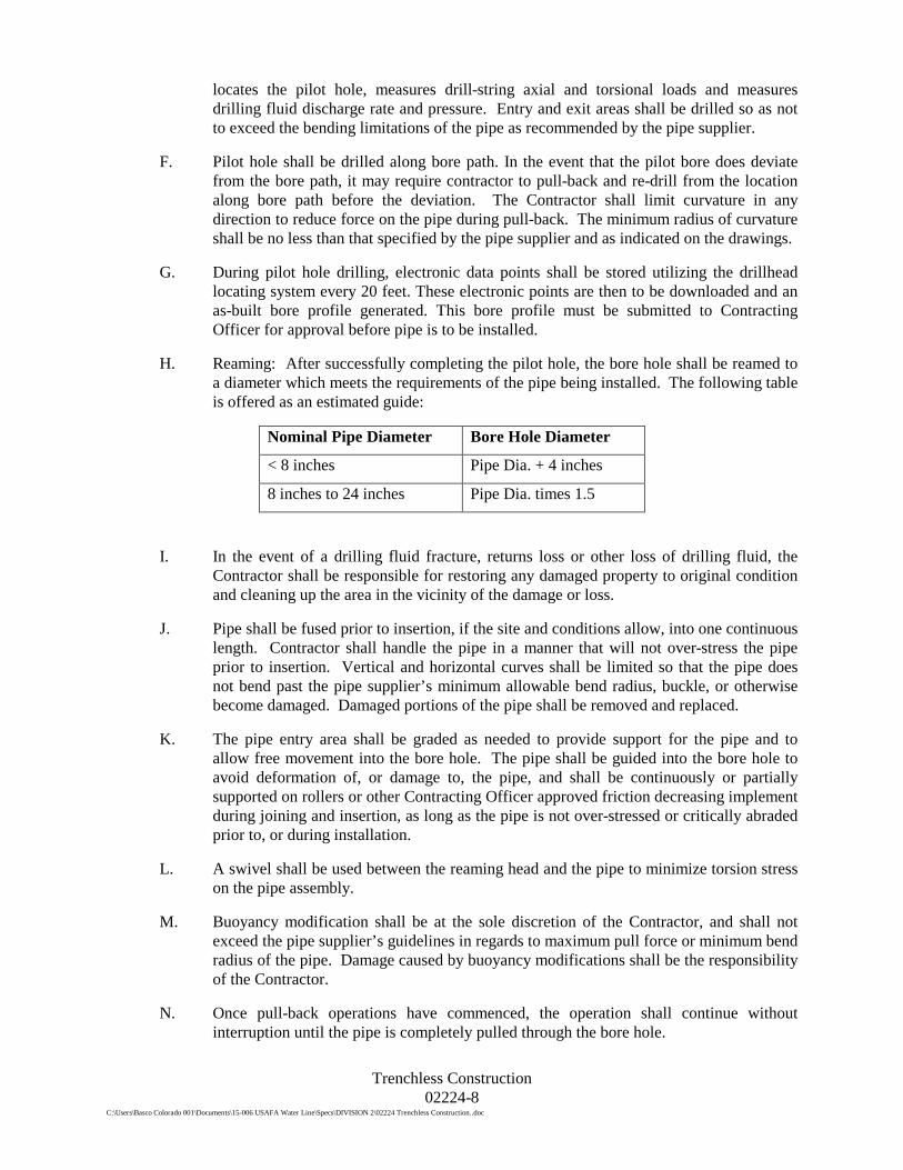
Trenchless Construction 02224-8
C:\Users\Basco Colorado 001\Documents\15-006 USAFA Water Line\Specs\DIVISION 2\02224 Trenchless Construction..doc
locates the pilot hole, measures drill-string axial and torsional loads and measures drilling fluid discharge rate and pressure. Entry and exit areas shall be drilled so as not to exceed the bending limitations of the pipe as recommended by the pipe supplier.
F. Pilot hole shall be drilled along bore path. In the event that the pilot bore does deviate from the bore path, it may require contractor to pull-back and re-drill from the location along bore path before the deviation. The Contractor shall limit curvature in any direction to reduce force on the pipe during pull-back. The minimum radius of curvature shall be no less than that specified by the pipe supplier and as indicated on the drawings.
G. During pilot hole drilling, electronic data points shall be stored utilizing the drillhead locating system every 20 feet. These electronic points are then to be downloaded and an as-built bore profile generated. This bore profile must be submitted to Contracting Officer for approval before pipe is to be installed.
H. Reaming: After successfully completing the pilot hole, the bore hole shall be reamed to a diameter which meets the requirements of the pipe being installed. The following table is offered as an estimated guide:
Nominal Pipe Diameter Bore Hole Diameter
< 8 inches Pipe Dia. + 4 inches
8 inches to 24 inches Pipe Dia. times 1.5
I. In the event of a drilling fluid fracture, returns loss or other loss of drilling fluid, the Contractor shall be responsible for restoring any damaged property to original condition and cleaning up the area in the vicinity of the damage or loss.
J. Pipe shall be fused prior to insertion, if the site and conditions allow, into one continuous length. Contractor shall handle the pipe in a manner that will not over-stress the pipe prior to insertion. Vertical and horizontal curves shall be limited so that the pipe does not bend past the pipe supplier’s minimum allowable bend radius, buckle, or otherwise become damaged. Damaged portions of the pipe shall be removed and replaced.
K. The pipe entry area shall be graded as needed to provide support for the pipe and to allow free movement into the bore hole. The pipe shall be guided into the bore hole to avoid deformation of, or damage to, the pipe, and shall be continuously or partially supported on rollers or other Contracting Officer approved friction decreasing implement during joining and insertion, as long as the pipe is not over-stressed or critically abraded prior to, or during installation.
L. A swivel shall be used between the reaming head and the pipe to minimize torsion stress on the pipe assembly.
M. Buoyancy modification shall be at the sole discretion of the Contractor, and shall not exceed the pipe supplier’s guidelines in regards to maximum pull force or minimum bend radius of the pipe. Damage caused by buoyancy modifications shall be the responsibility of the Contractor.
N. Once pull-back operations have commenced, the operation shall continue without interruption until the pipe is completely pulled through the bore hole.

Trenchless Construction 02224-9
C:\Users\Basco Colorado 001\Documents\15-006 USAFA Water Line\Specs\DIVISION 2\02224 Trenchless Construction..doc
O. Two (2) tracer wires shall be installed simultaneously with the pipe. The wires shall be attached to the drill head to be pulled with the pipe, but not attached to the length of the pipe.
P. The pipe shall be installed in a manner that does not cause upheaval, settlement, cracking, or movement and distortion of surface features. Any damages caused by the Contractor’s operations shall be corrected by the Contractor at no expense to the Owner.
Q. The Contractor shall allow for elongation of the pipe due to thermal or pulling forces. Pipe must be allowed to relax back to the original length before the bore is completed and tie-ins are installed. Installation procedure and pulling forces must be closely monitored so that the installed pipe does not exhibit failure due to yield.
3.6 FIELD TESTING AND DISINFECTION
A. Field testing and disinfection of potable water mains shall conform to the requirements of Section 02643 – Water Pipeline Testing and Disinfection.
END OF SECTION

Clearing and Grubbing 02230-1
C:\Users\Basco Colorado 001\Documents\15-006 USAFA Water Line\Specs\DIVISION 2\02230 Clearing and Grubbing.doc
SECTION 02230 CLEARING AND GRUBBING
PART 1 GENERAL
1.1 DESCRIPTION OF WORK
A. Removal of all surface debris, grass, trees, and shrubs from the disturbance limits indicated on the Drawings, and as required to perform the work.
B. The general work areas which require site clearing and grubbing include, but are not limited to:
1. Contractor staging and stockpile areas. 2. Pipeline alignment and surrounding areas that will be disturbed.
1.2 SUBMITTALS
A. Submit in accordance with Section 01330: Submittals.
B. Clearing and Grubbing Plan:
1. Describe method for vegetation removal and disposal. 2. Describe temporary barriers and methods to protect existing structures and
property, existing plant life and features designated to remain, and areas beyond limits of disturbance as identified on the Drawings.
PART 2 PRODUCTS
NOT USED
PART 3 EXECUTION
3.1 PROTECTION
A. Verify the area to be cleared and existing plant life and features designated to remain with the Contracting Officer before initiating any clearing operations in that area. Unauthorized clearing will not be approved for payment, and the Contractor is responsible for replacement of damaged existing plant life and features designated to remain.
B. Flag, barricade and clearly mark existing plant life and features designated to remain.
C. Protect any trees, plant growth, and site features not designated for removal or designated for protection. Remove only those trees and plant growth required for the Work.
D. Do not disturb trees or shrubbery in public right-of-way or on property outside of the limits of disturbance shown on the Drawings.

Clearing and Grubbing 02230-2
C:\Users\Basco Colorado 001\Documents\15-006 USAFA Water Line\Specs\DIVISION 2\02230 Clearing and Grubbing.doc
3.2 CLEARING AND GRUBBING
A. Remove all trees, shrubs, undergrowth, deadwood, and other surface debris as required to perform the Work, within the limits of disturbance shown on the Drawings, except for those trees and shrubs designated to be protected.
B. Remove all trees, stumps, branches, brush and other material from clearing and grubbing activities. Cut tree trunks and branches into 10-foot maximum lengths and stockpile in staging and stockpile areas designated on the Drawings.
C. Remove and stockpile topsoil in accordance with Section 02235: Stripping and Stockpiling Topsoil.
D. Do not leave logs, stumps, rocks, etc., lying in the public right-of-way or on adjacent property without written approval by the Contracting Officer.
3.3 DAMAGED VEGETATION
A. Contractor is responsible for injuries to vegetation caused by Contractor operations, personnel, or equipment. Remove and replace damaged vegetation designated for protection with vegetation of same type and size at no additional cost to the Owner.
3.4 PLACEMENT AND DISPOSAL
A. It is expected that much of the clearing and grubbing vegetative materials can be used on site to create wildlife habitat and other natural features.
B. Dispose of excess vegetative materials and debris materials in accordance with all applicable rules and laws.
3.5 MAINTENANCE OF CLEARED AREAS
A. Maintain cleared work areas in a condition free from additional vegetation growth for the duration of the project.
B. Compensation for clearing each area will occur only one time. If weeds and brush growth require additional clearing, this shall be performed solely at the Contractor’s expense.
END OF SECTION

Stripping and Stockpiling Topsoil 02235-1
C:\Users\Basco Colorado 001\Documents\15-006 USAFA Water Line\Specs\DIVISION 2\02235 Stripping and Stockpiling Topsoil.doc
SECTION 02235 STRIPPING AND STOCKPILING TOPSOIL
PART 1 GENERAL
1.1 DESCRIPTION OF WORK
A. Removing grass, weeds, and topsoil within the limits of site disturbance as shown on the Drawings.
B. Stockpiling topsoil in the staging and stockpile areas approved by the Contracting Officer.
1.2 DEFINITIONS
A. Topsoil – Topsoil stripped from the site shall be the top surface soil that is dark brown or black, fertile, and contains organic matter or the soil that is located within 12 inches of the surface, or as directed by the Contracting Officer. Topsoil shall be free of subsoil, noxious weed seed or reproductive vegetation plants, heavy clay, hard clods, toxic substances or other material which would be detrimental to plant growth.
PART 2 PRODUCTS
NOT USED
PART 3 EXECUTION
3.1 GENERAL
A. Excavate topsoil from areas requiring stripping, as indicated on the Drawings or as directed by the Contracting Officer.
B. Remove roots larger than 1 inch, rocks larger than 3 inches, and debris prior to stockpiling of the topsoil, unless determined otherwise by the Contracting Officer. Existing grass layers may be incorporated into topsoil provided the layers are mixed adequately into the topsoil stockpiles.
C. Stockpile topsoil in area(s) designated on the Drawings unless otherwise approved.
D. Limit height of topsoil stockpiles to 4 feet unless otherwise approved.
E. Install erosion protection around all stockpiles. Protect topsoil stockpiles from wind and water erosion.

Stripping and Stockpiling Topsoil 02235-1
C:\Users\Basco Colorado 001\Documents\15-006 USAFA Water Line\Specs\DIVISION 2\02235 Stripping and Stockpiling Topsoil.doc
3.2 DISPOSAL
A. Remove and dispose of excess vegetation not required to create wildlife habitat or for reclamation activities as directed by the Contracting Officer at an off-site facility in accordance with the requirements of Division 1 Specifications as well as applicable local, state, or federal rules and regulations.
END OF SECTION

HDPE Pipe 02510-1
C:\Users\Basco Colorado 001\Documents\15-006 USAFA Water Line\Specs\DIVISION 2\02510 HDPE Pipe.doc
SECTION 02510 HDPE PIPE
PART 1 GENERAL
1.1 DESCRIPTION OF WORK
A. High density polyethylene (HDPE) pipe, as shown on the Drawings.
1.2 REFERENCES FOR HDPE PIPE
ASME B40.1 Gauges – Pressure Indicating Dial Type AWWA C 906 AWWA Standard for Polyethylene (PE) Pressure Pipe and Fitting for
Water, 4 In. Through 63 In., for Water Distribution AWWA M55 PE Pipe Design and Installation ASTM F1055 Standard Specification for Electrofusion Type Polyethylene Fittings
for Outside Diameter Controlled Polyethylene Pipe and Tubing ASTM D3261 Standard Specification for Butt Heat Fusion Polyethylene (PE)
Plastic Fittings for Polyethylene (PE) Plastic Pipe and Tubing ASME/ANSI B16.5 Pipe Flanges and Flanged Fittings ASTM C 177 Test Method for Steady-State Heat Flux Measurement and Thermal
Transmission Properties by Means of the Guarded-Hot-Plate Apparatus ASTM D 152S Test Method for Vicat Softening Temperature of Plastics ASTM D 256 Test Method for Impact Resistance of Plastics and Electrical Insulating
Material ASTM D 746 Test Method for Brittleness Temperature of Plastics and Elastomers by
Impact ASTM D 638 Test Method for Tensile Properties of Plastics ASTM D 695 Test Method for Compressive Strength of Rigid Plastics ASTM D 696 Test Method of Coefficient of Linear Thermal Expansion of Plastics ASTM D 746 Test Method for Brittleness Temperature of Plastics and Elastomers by
Impact ASTM D 790 Test Method for Flexural Properties of Unreinforced and Reinforced
Plastics and Electrical Insulating Materials ASTM D 1238 Test Method for Flow Rates of Thermal Plastics Molding and
Extrusion Materials ASTM D 1248 Specification for Polyethylene Plastics Molding and Extrusion Material ASTM D 1505 Test Method for Density of Plastics by the Density-Gradient Technique ASTM D 1599 Test Method for Short Time Hydraulic Failure Pressure of Plastic Pipe
Materials ASTM D 1693 Test Method for Environmental Stress Cracking of Ethylene Plastics ASTM D 2122 Method for Determining Dimensions of Thermal Plastic Pipe and
Fittings ASTM D 2240 Test Method of Rubber Property - Durometer Hardness ASTM D 2837 Method for Obtaining Hydrostatic Design Basis for Thermal Plastic
Pipe Materials ASTM D 3350 Polyethylene Plastics Pipe and Fitting Material ASTM D 4218 Test Method for Carbon Black Content in Polyethylene Compounds by
the Muffle-Furnace Technique ASTM F 714 Polyethylene (PE) Plastic Pipe Based on Outside Diameter

HDPE Pipe 02510-2
C:\Users\Basco Colorado 001\Documents\15-006 USAFA Water Line\Specs\DIVISION 2\02510 HDPE Pipe.doc
ASTM F 1248 Determination of Environmental Stress Crack Resistance (ESCR) of Polyethylene Pipe
AWS B2.1 Standard for Welding Procedure and Welding Qualifications.
1.3 SUBMITTALS
A. Submit in accordance with Specification Section 01330.
B. Fusion Welder Qualifications: All fusion welding shall be done by skilled welders, welding operators, who have had adequate experience in the methods and materials to be used. Welders shall be qualified by the manufacturer not more than 6 months prior to commencing work on the pipeline. Machines and electrodes similar to those used in the Work shall be used in qualification tests
C. Product Data:
1. Submit for piping materials, fittings, and jointing methods; and recommended methods of installation of pipe and construction of bends in pipe
2. Furnish a certified affidavit of compliance for all pipe and other products or materials furnished under this specification. Submit certificates furnished by the manufacturer certifying that pipe and fitting materials comply with the requirements specified in Part 2 of this Specification.
D. Shop Drawings shall be submitted in accordance with Section 01330 for approval and shall include the following:
1. Dimensional drawings of all pipe and appurtenances that are provided in accordance with this specification.
2. Details of standard pipe, specials, and fittings. 3. Pressure testing for water tightness procedure in accordance with ASTM F 2164.
E. Submit a testing schedule, including proposed plans for water conveyance, control and disposal. Incorporate testing schedule with Section 01320, Construction Progress Schedules.
1.4 QUALITY CONTROL
A. Materials, manufacturing and testing shall meet AWWA C906 standards including but not limited to source materials, manufacturer qualifications, workmanship, dimensions and tolerances, bend-back test, elongation-at-break test, ring-tensile strength test, carbon black content, five-second pressure test, melt-flow index, density and marking requirements.
B. The Contractor shall submit data logger test reports to the Contracting Officer for review prior to HDPE pipe pressure and leakage testing.
PART 2 PRODUCTS
2.1 HIGH DENSITY POLYETHYLENE PIPE (HDPE)
A. General

HDPE Pipe 02510-3
C:\Users\Basco Colorado 001\Documents\15-006 USAFA Water Line\Specs\DIVISION 2\02510 HDPE Pipe.doc
1. The HDPE pipeline shall consist of HDPE conduits, molded fittings, and any necessary elbows and fittings for a complete installation.
2. The Contractor shall verify that the pipe fittings, pipe and all appurtenances provided by the Contractor are compatible.
3. Pipe and fittings shall be marked in accordance with AWWA C906 and shall include at a minimum but not limited to nominal size, material designation, dimensional ratio, pressure class, AWWA designation, manufacturer and test category.
4. Service identification stripes: Use blue stripe to indicate potable water and white stripe to indicate non-potable water. Provide permanent identification by co-extruding white color stripe into pipe outside surface. Use striping material as same material as pipe material except for color
B. Pipe and Fittings
1. Pipe and fittings shall be manufactured with extra-high-molecular weight, high-density ethylene/hexene copolymer PE 4710 polyethylene resin with an ASTM D 3350 cell classification number of 445474C. Use only materials listed by the Plastics Pipe Institute in PPI TR-4 with a 73oF hydrostatic design-basis rating of 1600 psi and a 140oF hydrostatic design-basis rating of 800 psi; PPI listing based on ASTM D 2837 and PPI TR-3 testing and validation of manufacturer’s production-pipe samples. Manufacture to dimensions and tolerances specified in ASTM F 714, and factory inspect per industry standards.
2. Pipes and fittings shall be joined by butt fusion, in accordance with the manufacturers recommended procedures.
3. Pipe flanges and connections shall be installed where shown on the Drawings. The Contractor shall supply all materials to adequately assemble all joints.
4. HDPE pipe for this project shall all be standard dimensional ratio (SDR) 9.
C. Joining Methods
1. General: Joining methods shall only be used as approved by the Contracting Officer.
2. Butt Fusion Welding. Polyethylene pipe and fittings may be joined together using butt-weld joints in strict accordance with manufacturer's instructions. Use heat-fusion equipment meeting conditions recommended by pipe manufacturer, including, but not limited to, temperature requirements of 440 Deg F ± 10 Deg F, alignment, and 75-psi interfacial-fusion pressure.
3. Mechanical Joining. Polyethylene pipe and fittings may be joined together using Flanges or Mechanical Joint (MJ) adapters. These fittings shall be made from PE 4710 HDPE, Cell Classification of 445474C as determined by ASTM D3350.
4. Flanged and MJ adapters shall have a manufacturing standard of ASTM D3261. They shall have a pressure rating equal to the pipe unless otherwise specified on the Drawings. The HDPE flange assembly shall consist of a metal backer ring or flange and a HDPE stub-end or adapter in accordance with AWWA C906.
5. All other joining methods shall be approved by the Contracting Officer.
2.2 HDPE FITTINGS:
A. In accordance with AWWA C906.
HDPE Pipe 02510-4
C:\Users\Basco Colorado 001\Documents\15-006 USAFA Water Line\Specs\DIVISION 2\02510 HDPE Pipe.doc
B. Manufactured from the same resin type, grade, and cell classification as the pipe, and conforming to the same physical properties. As uniform as commercially practical in color, opacity, density and other physical properties.
C. Manufactured by injection molding or by extrusion and machining, or fabricated from polyethylene pipe conforming to specified pipe dimensions.
D. Fully pressure-rated with a working pressure equal to that of pipe for 50-years service at 73.4oF, with a safety factor of 2.
E. Flange fittings shall have compatible wall thickness of each corresponding pipe. Do not use stub ends to substitute flange adapters. Include back-up rings, epoxy coated ductile iron for direct burial application in accordance with ASTM 53 B, Grade 65/45/12, ANSI Class 150 Standard unless noted otherwise.
2.3 DUCTILE IRON FITTINGS
A. All fittings shall be manufactured in accordance with AWWA C104, C110, C111, C151 and C153.
B. All fittings shall have one of the following types of connections:
1. Flanged joint. 2. Mechanical joint.
C. All fittings shall be made of either gray-iron or ductile iron, and have a minimum working pressure rating equal to or greater than the adjacent pipeline. In any case for pipeline segments having working pressures equal to or less than 250 psi, the minimum working pressure rating of fittings shall be 250 psi.
D. All sizes of ductile and gray iron fittings shall be furnished with a cement-mortar lining of standard thickness and given a seal coat of bituminous material.
E. Iron used in the manufacture of fittings for these specifications shall have:
1. Minimum tensile strength - 60,000 psi 2. Minimum yield strength - 42,000 psi 3. Minimum elongation - 10 percent
F. POLYETHYLENE ENCASEMENT
1. All buried ductile iron fittings shall be installed with polyethylene pipe encasement manufactured in accordance with AWWA C105.
a. Polyethylene encasement shall be provided specifically for the size of pipe used.
b. Polyethylene encasement shall be high-density, cross-linked. c. Minimum thickness of polyethylene shall be 4 mil.
G. CATHODIC PROTECTION
1. All ductile iron fittings and valves shall have cathodic protection as shown on the Drawings.

HDPE Pipe 02510-5
C:\Users\Basco Colorado 001\Documents\15-006 USAFA Water Line\Specs\DIVISION 2\02510 HDPE Pipe.doc
2.4 PIPE BEDDING
A. Pipe bedding material required for direct-buried HDPE pipes shall be clean or gravelly sand or onsite material graded to following limits:
TABLE 02510-1 PIPE BEDDING GRADATION
US Standard Sieve Size
Total Percent Passing by Weight
3/8 inch 100
No. 4 95-100
No. 8 80-100 No. 16 50-85 No. 30 25-60 No. 50 10-30 No. 100 2-10
PART 3 EXECUTION
3.1 HDPE PIPELINE
A. Quality Control
1. The Contractor shall verify the pipe, fittings and joining methods with the manufacturer for the intended application.
2. The fusion equipment operator shall have previous experience in fusing the specified pipe type and size and shall have received training from the manufacturers authorized representative for pipe fusion. The Contractor shall be responsible to verify that the fusion equipment is in good operating condition and that the operator has been trained within the past 12 months. The fusion equipment shall be equipped with a Datalogger. Records of the welds (heater temperature, fusion pressure, and a graph of the fusion cycle) shall be supplied to the Contracting Officer.
B. Protection and Testing
1. Impose no traffic loads on pipe and structures until the pipe has been covered to a depth sufficient to prevent damage or breakage
2. The completed HDPE installation shall be watertight as determined by the testing plan submitted by Contactor prior to starting installation and as approved by Contracting Officer.
3. Contractor shall furnish all materials necessary for completing tests and bear all costs connected therewith.
4. Tests shall be performed under the observation of Contracting Officer.
C. Trenching and Backfilling
1. Where buried pipe is shown on the drawings, excavate trenches to lines and grades indicated and as required to permit installation of pipe and backfill materials specified and as shown on the Drawing Details.
HDPE Pipe 02510-6
C:\Users\Basco Colorado 001\Documents\15-006 USAFA Water Line\Specs\DIVISION 2\02510 HDPE Pipe.doc
2. Verify all lines, grades, and measurements before installing pipes. 3. Grade and shape the bottom of the excavation to provide a firm and uniform
bearing. 4. Place pipe bedding and overlying material in a manner which will not damage or
displace the pipe. 5. Support pipe with bedding or backfill prior to backfilling above pipe. 6. Remove deposits of mud, sand, gravel or other foreign matter from the pipe
system using method(s) approved by the Contracting Officer. 7. Backfill shall be compacted by vibrating, and/or tamping to the satisfaction of
the Inspector. Compaction for cohesionless soils shall be a minimum compaction requirement of 95% of maximum Modified Proctor dry density at +/- 2% optimum content, and 100% maximum Standards Proctor dry density (ASTM D698) at +/- 2% of optimum content. Compaction tests shall be taken every 250 ft at depths specified.
8. Cold Weather Protection: No pipe shall be installed upon a foundation into which frost has penetrated or at any time that there is a danger of the formation of ice or penetration of frost at the bottom of the excavation. No pipe shall be laid unless it can be established that the trench will be backfilled before the formation of ice and frost occurs.
9. Perform pipeline flushing and pressure testing in accordance with specification Section 02643.
D. Installation
1. Inspect pipe and fittings prior to assembly. Mark and remove from jobsite materials that are damaged or do not meet these Specifications.
2. Remove, repair and/or replace obstructions or deformations in the pipes at no expense to the Owner. Cut out and remove sections of pipe with cuts or gouges in excess of 10% of the wall thickness.
3. Confirm location of pipe, fittings and connections. 4. Handle and install in accordance with manufacturer's recommendations. 5. To control temperature stresses, the unbackfilled joint areas of the pipe shall be
shaded from the direct rays of the sun by the use of properly supported awnings, umbrellas, tarpaulins, or other suitable materials for a minimum period of 2 hours prior to the beginning of the welding operation and until the weld has been completed. Shading materials at the joint area shall not rest directly on the pipe but shall be supported to allow air circulation around the pipe. Shading of the pipe joints need not be performed when the ambient air temperature is below 45 degrees Fahrenheit.
6. Joining:
a. Butt-weld joints in strict accordance with manufacturer's instructions. Use heat-fusion equipment meeting conditions recommended by pipe manufacturer, including, but not limited to, temperature requirements of 440 Deg F ± 10 Deg F, alignment, and 75-psi interfacial-fusion pressure.
b. Saddle fusion, where approved, shall be completed in strict accordance with manufacturer's instructions.
c. Produce joint-weld strengths equal to or greater than the tensile strength of the pipe.
d. Socket fusion is prohibited.

HDPE Pipe 02510-7
C:\Users\Basco Colorado 001\Documents\15-006 USAFA Water Line\Specs\DIVISION 2\02510 HDPE Pipe.doc
e. Solvent cement, adhesive, threaded type or other any other joining methods are prohibited
7. HDPE Flange with Backing Ring Installation. Flanges/Backing Rings shall be attached to HDPE pipe and fittings using butt fusion. The Flanges/Backing Rings shall be aligned and centered relative to the pipe. Flanges/Backing Rings should be square with the valve or other flange before tightening of bolts. Bolts should not be used to draw flanges into alignment. Bolt threads shall be lubricated, and flat washers shall be used under flange nuts. Bolts shall be tightened using a “star-tightening pattern”. See manufacturer’s recommendations. Twenty-four hours after first tightening the flange bolts, they must be re-tightened using the same “star-tightening pattern used above. The final tightening torque shall be as indicated by the manufacturer.
8. Visually inspect all joints for proper configuration of HDPE joints, fitting or fusion welds.
9. Contractor shall take precaution when handling pipe segments that have been fusion welded together. If joint becomes damaged Contractor shall cut the pipe and re-join the pipe in accordance with these specifications.
END OF SECTION

Combination Air-Release & Air-Vacuum Valves 02514-1
C:\Users\Basco Colorado 001\Documents\15-006 USAFA Water Line\Specs\DIVISION 2\02514 Air Vac Valves.doc
SECTION 02514 COMBINATION AIR-RELEASE & AIR-VACUUM VALVES
PART 1 GENERAL
1.1 DESCRIPTION OF WORK
A. Combination air release and air vacuum valves as shown on the Drawings.
1.2 REFERENCES
A. American Water Works Association (AWWA)
1. AWWA C500 Metal Seated Gate Valves for Water Supply Service
B. American Society for Testing and Materials (ASTM)
1. ASTM F 104 Standard Classification System for Nonmetallic Gasket Materials
1.3 SUBMITTALS
A. Submit in accordance with Section 01330: Submittals.
B. Shop Drawings:
1. Valves:
a. Product data sheets for make and model. b. Complete catalog information, descriptive literature, Specifications, and
identification of materials of construction.
2. Gaskets: Product data sheet for make and model.
C. Quality Control Submittals:
1. Tests and inspection data 2. Operation and maintenance manual
1.4 QUALITY ASSURANCE
A. Furnish valves and fittings from manufacturers who are fully experienced, certified, reputable, and qualified in the manufacture of the products to be furnished.
1.5 DELIVERY, STORAGE, AND HANDLING
A. Handle products in accordance with the manufacturer’s instructions.
PART 2 PRODUCTS
2.1 COMBINATION AIR-RELEASE AND AIR-VACUUM VALVES
A. Combination Air Valves shall be automatic float operated valves designed to exhaust large quantities of air during the filling of a piping system and close upon liquid entry. The valve shall open during draining or if a negative pressure occurs. The valve shall

Combination Air-Release & Air-Vacuum Valves 02514-2
C:\Users\Basco Colorado 001\Documents\15-006 USAFA Water Line\Specs\DIVISION 2\02514 Air Vac Valves.doc
also release accumulated air from a piping system while the system is in operation and under pressure. The valve shall perform the functions of both Air Release and Air/Vacuum Valves and furnished as a single body or dual body type as indicated on the plans.
B. Dual body valve sizes 3 in and smaller and single body valve sizes 4 in and smaller shall have full size NPT inlets and outlets equal to the nominal valve size. The body inlet connection shall be hexagonal for a wrench connection.
C. Larger sizes shall have bolted flanged inlets and plain outlets and protective hoods to prevent debris from entering the valve. Flanges shall be in accordance with ANSI B16.1 for Class 125 or Class 250 iron flanges and ANSI B16.5 for Class300 steel flanges.
D. The valve shall have two additional NPT connections for the connection to gauges, testing, and draining.
E. Design:
1. Both single and dual body valves shall provide a through flow area equal to the nominal size. Floats shall be unconditionally guaranteed against failure including pressure surges. The cover shall be bolted to the body and sealed with a flat gasket.
2. A resilient bumper shall be provided on 4 in and larger sizes to cushion the float during sudden opening conditions. The resilient seat shall be replaceable and provide drop tight shut off to the full valve pressure rating.
3. Dual body combination valves shall consist of an Air Release Valve piped to an Air/Vacuum Valve with a quarter-turn, full-ported bronze ball valve.
4. The Air Release Valve shall have a leverage mechanism with sufficient mechanical advantage so that the valve will open under full operating pressure. Simple lever designs shall consist of a single pivot arm and a resilient orifice button. Compound lever designs shall consist of two levers and an adjustable threaded resilient orifice button.
5. The Air/Vacuum Valve sizes 4 in and larger shall have a cover fitted to the valve body by means of a machined register to maintain concentricity between the top and bottom guide bushings at all times. The float shall be double guided with a guide shaft extending through the float to prevent any contact with the body. The float shall be protected against direct water impact by an internal baffle bolted to the cover or integrally cast in the body. The seat shall be a minimum of .5 in thick on 2 in and larger valves and secured in such a manner as to prevent distortion. Valves with working pressures above 400 psig shall have metal seats with synthetic seals.
6. Single body combination valves shall have an expanded outlet to provide full flow area around the guide mechanism. The valve shall have a double guided plug on 2 in and larger sizes, and an adjustable threaded orifice button. The plug shall be protected against direct water impact by an internal baffle. On valve sizes 4 in and smaller, the plug shall have a precision orifice drilled through the center stem. On valve sizes 6 in and larger, air release and air/vacuum mechanisms shall be provided as separate units contained within the same body and meet the same design specifications for the Dual Body Combination Valve.
F. Materials:

Combination Air-Release & Air-Vacuum Valves 02514-3
C:\Users\Basco Colorado 001\Documents\15-006 USAFA Water Line\Specs\DIVISION 2\02514 Air Vac Valves.doc
1. The valve body and cover shall be constructed of ASTM A126 Class B cast iron for Class 125 and Class 250 valves. Class 300 ductile iron valves shall be constructed of ASTM A536 Grade 65-45-12 ductile iron. Dual Body Class 300 steel valves shall be constructed of ASTM A216 Grade WCB cast steel.
2. The float, guide shafts, and bushings shall be constructed of Type 316 stainless steel. Non-metallic floats, linkage, or bushings are not acceptable. Resilient seats shall be Buna-N. Class 300 steel dual body valves shall have a 316 stainless steel seat with Buna-N seal to provide an initial contact to Buna-N with a final metal-to-metal contact to prevent over compression of the resilient seal.
3. The exterior of the valve shall be coated with a universal alkyd primer.
G. Manufacture:
1. The manufacturer shall demonstrate a minimum of five (5) years experience in the manufacture of air valves. When requested, the manufacturer shall provide test certificates, dimensional drawings, parts list drawings, and operation and maintenance manuals.
2. Manufacturer shall have a quality management system that is certified to ISO 9001:2000 by an accredited, certifying body.
3. Valves shall be manufactured and tested in accordance with American Water Works Association (AWWA) Standard C512
4. Combination Air Release Valves shall be Series VM 203C, 3-inch single body type as manufactured by Val-Matic and Manufacturing Corporation, Elmhurst, Il, USA or approved equal.
PART 3 EXECUTION
3.1 INSTALLATION
A. Install combination air and vacuum valves in a vertical arrangement as required by the manufacturer and as shown on the Drawings.
B. Provide bolt packs, gaskets, and other materials as required for proper installation.
C. All air release valve assemblies shall be installed with a ball valve isolation valve mounted between the air release valve and waterline. Isolation ball valve end connections shall be coordinated by the Contractor to match the size and type of pipe end connections for the air release valve requirements.
3.2 FIELD QUALITY CONTROL
A. Repair damaged coatings using original coating materials in accordance with manufacturer's instructions.
END OF SECTION

Water Pipeline Testing and Disinfection 02643-1
C:\Users\Basco Colorado 001\Documents\15-006 USAFA Water Line\Specs\DIVISION 2\02643 Water Pipe Testing and Disinfection..doc
SECTION 02643 WATER PIPELINE TESTING AND DISINFECTION
PART 1 GENERAL
1.1 SECTION INCLUDES
A. This section includes testing requirements of all waterlines including: Reference Specifications, Codes, and Standards; Contractor Submittals; Material Requirements; General Execution; Hydrostatic Testing of Pipelines; Disinfecting Pipelines; Connections to Existing System; Disposal and Dechlorination of Chlorinated Flush Water.
1.2 REFERENCE SPECIFICATIONS, CODES, AND STANDARDS
A. Commercial Standards:
1. ANSI/AWWA B300 Hypochlorites. 2. ANSI/AWWA B301 Liquid Chlorine. 3. ANSI/AWWA C651 Disinfecting Water Mains. 4. ANSI/AWWA B40.1 Pressure Tests 5. AWWA M55 PE Pipe Design and Installation
1.3 CONTRACTOR SUBMITTALS
A. Submit a testing schedule, including proposed plans for water conveyance, control, disposal, and disinfection. Incorporate testing schedule with Section 01320, Construction Progress Schedule.
B. Coordinate with the critical dates of Section 01010, Summary of Work.
C. Disposal plan for highly chlorinated water. Including:
1. Narrative of procedures 2. Location of any flushing discharge point 3. Type and form of sodium bi-sulfate used 4. Temporary detention facilities, location and size 5. Fully executed and State approved Discharge permit 6. Chlorine residual testing methods 7. Date and time of flushing and chemical use start day and time
D. Disinfection Report, Contractor shall record the following:
1. Type and form of disinfectant used 2. Date and time of disinfectant injection start day and time of completion 3. Test locations 4. Initial and 24 hour disinfectant residuals (quantity in treated water) in ppm for
each outlet tested 5. Date and time of flushing start and completion 6. Disinfectant residual after flushing in ppm for each outlet tested
E. Bacteriological report, Contractor shall record the following:

Water Pipeline Testing and Disinfection 02643-2
C:\Users\Basco Colorado 001\Documents\15-006 USAFA Water Line\Specs\DIVISION 2\02643 Water Pipe Testing and Disinfection..doc
1. Date issued, project name and testing laboratory name, address and telephone number
2. Time and date of water sample collection 3. Name of person collecting samples 4. Test locations 5. Initial and 24-hour disinfectant residuals in ppm for each outlet tested 6. Coliform bacteria test results for each outlet tested 7. Certification that water conforms, or fails to conform to bacteriological
standards of Colorado Department of Public Health and Environment 8. Bacteriologist’s signature and authority
PART 2 PRODUCTS
2.1 MATERIALS REQUIREMENTS
A. Contractor shall furnish, provide, install and remove all temporary pumps, air compressors, pipe, valves, bulkheads, retention facilities, appurtenances and accessories, chemicals and test kits needed to obtain or transport water and perform the tests and flushing, test equipment, connections for chlorination, or other water control equipment and materials, subject to the Contracting Officer’s review. Do not use materials that would be injurious to the construction or its future function.
B. The Owner will provide domestic potable water for testing and flushing from existing, designated sources. Contractor shall receive and transport water from the point of supply by the Owner to the location required to perform the specified tests.
C. Contractor shall secure all necessary permits from regulatory agencies for flush water discharge.
D. All test equipment shall be disinfected using water having a chlorine residual of at least 100 mg/l before installation on the pipelines.
E. Provide certified digital gauges for pressure tests, 0-400 psi, accuracy grade of 2A or better per ANSI B40.1, or ASCROFT Model 2530C09, 0/400 psi, or equal.
F. Chlorine for disinfection shall be provided by the Contractor and may be in the form of liquid chlorine, sodium hypochlorite solution, or calcium hypochlorite granules or tablets. Gas shall not be permitted.
G. Sodium Bi-sulfite for dechlorination provided by the Contractor may be in the form of liquid, granules or tablets. Gas shall not be permitted.
PART 3 EXECUTION
3.1 GENERAL
A. Any work on the waterlines will have to be coordinated with Bioenvironmental/CEOSU for proper disinfection and testing.
B. Contractor shall make all necessary provisions for conveying the water from the Owner-designated source to the points of use.

Water Pipeline Testing and Disinfection 02643-3
C:\Users\Basco Colorado 001\Documents\15-006 USAFA Water Line\Specs\DIVISION 2\02643 Water Pipe Testing and Disinfection..doc
C. Contractor shall pressure test all pressure pipelines using water as the test medium as specified for the applicable pipe specifications. Perform test operations in the presence of the Contracting Officer.
D. After satisfactory pressure testing and repair of any leakage, Contractor shall disinfect the potable water pipelines. Perform disinfection operations in the presence of the Contracting Officer.
E. Non-potable water pipelines and drain pipelines shall be pressure tested as specified, disinfection is not required.
F. Schedule disinfection operations as late as possible during the contract time period so as to assure the maximum degree of sterility of the facilities at the time the Work is accepted by the Owner. Bacteriological testing will be performed by a certified testing laboratory approved by the Owner, paid for by the Contractor. Results of the bacteriological testing shall be satisfactory with the State Department of Health and Environment or other appropriate regulatory agency.
3.2 HYDROSTATIC TESTING OF PIPELINES
A. Prior to hydrostatic testing, thoroughly clean and flush or blow out pipelines, as appropriate. Test pipelines in sections to ensure that in-line valves are leak tight. No section of the pipeline shall be tested until all field-placed concrete or mortar has attained an age of at least 14 days or 75-percent of design strength minimum. Make the test by closing valves when available, or by placing temporary bulkheads in the pipe and filling the line slowly (less than 0.5 feet per second) with water. Ensure that test bulkheads are suitably restrained to resist the thrust of the test pressure without damage to, or movement of, the adjacent pipe. Ensure that air vents are open during filling and blow-off valves are closed.
B. Fill the pipeline at a rate that will not cause any surges or exceed the rate at which the air can be released through the air valves at a reasonable velocity and all the air within the pipeline is properly purged. After the pipeline or section thereof has been filled, allow to stand under a slight pressure for at least 12 hours to allow the escape of air from any air pockets. During this period, examine bulkheads, valves, and connections for leaks. If leaks are found, take corrective measures satisfactory to the Contracting Officer.
C. All visible leaks shall be repaired regardless of leakage rate. Repair visible leaks in a manner acceptable to the Contracting Officer.
D. During the initial expansion time, the pipe will expand and require makeup water to maintain pressure.
E. The hydrostatic test is complete when the pressure remains steady (within 5 percent of the target value) for one hour. The test pressure for distribution and transmission pipelines shall be 1.5 times the working pressure of 200 psi.
F. Distribution and transmission pipelines with welded joints shall have no leakage. In the case of pipelines that fail to pass the prescribed leakage test, determine the cause of the leakage, take corrective measures necessary to repair the leaks, and again test the pipelines. Continue until the pipeline passes the test.
Water Pipeline Testing and Disinfection 02643-4
C:\Users\Basco Colorado 001\Documents\15-006 USAFA Water Line\Specs\DIVISION 2\02643 Water Pipe Testing and Disinfection..doc
3.3 DISINFECTING PIPELINES
A. General: All potable water pipelines will be disinfected by the Contractor in accordance with the requirements of ANSI/AWWA C651 using the Continuous-Feed Method as modified herein.
B. Flush, test and disinfect the pipeline in at least two segments using domestic potable water.
C. Chlorination: Slug method.
D. Chlorinating Valves: During the process of chlorinating the pipelines, operate valves and other appurtenances while the pipeline is filled with the heavily chlorinated water.
E. Final Flushing: After the applicable retention period, Contractor shall flush the heavily chlorinated water from the two segments of pipeline until chlorine measurements show that the concentration in the water leaving the pipeline is no higher than that generally prevailing in the system or is acceptable for domestic use or until the residual of 0.5 mg/l is achieved. If there is any question that the chlorinated discharge will cause damage to the environment, Contractor shall add a reducing agent to the water to neutralize thoroughly the chlorine residual remaining in the water. Contractor shall obtain all necessary discharge permits including those specified in Section 01310, Construction Schedules.
F. Clean and disinfect all blow-off manholes and interior blow-off piping and flush prior to use as disposal for flush water to prevent cross-contamination of the water pipeline. All equipment and pumps used for disposal of flush water shall be disinfected using water having a chlorine residual of 100 mg/l.
G. Service Lines: All new service lines shall be flushed and disinfected as outlined above. Flush the ends of service lines from the main pipeline to the meter at the point of connection to the meter prior to connecting.
H. Bacteriological Testing: After final flushing and before the pipeline is placed in service, Contractor shall collect samples from the end of the line for testing for bacteriological quality in accordance with the requirements of the State Department of Health or other appropriate regulatory agency. For this purpose, all heavily chlorinated water and flush water will be flushed from the pipeline before any sample is collected. Should the initial disinfection treatment fail to produce satisfactory bacteriological test results, the disinfection procedure will be repeated until acceptable results are obtained.
1. Take samples at each terminal of the pipeline segment being tested 2. Take samples no sooner than 24-hours after flushing 3. Take samples from all air release valves, all blow-offs and all temporary test
bulkheads.
3.4 CONNECTIONS TO EXISTING SYSTEM
A. Where connections are to be made to an existing potable water system, swab or spray interior surfaces of all pipe and fittings used in making the connections with a one percent hypochlorite solution before they are installed. Thoroughly flush as soon as the connection is completed and continue until discolored water is eliminated.
END OF SECTION

Precast Concrete 03410-1
C:\Users\Basco Colorado 001\Documents\15-006 USAFA Water Line\Specs\DIVISION 3\03410 PreCast Concrete (1).doc
SECTION 03410 PRECAST CONCRETE
PART 1 GENERAL
1.1 DESCRIPTION OF WORK
A. Precast concrete manholes.
1.2 REFERENCES
A. ASTM C 891: Installation of Underground Precast Concrete Utility Structures
B. ASTM C 1433: Standard Specification for Precast Reinforced Concrete Box Sections for Culverts, Storm Drains, and Sewers
C. ASTM C 1577: Standard Specifications for Precast Reinforced Concrete Box Sections for Culverts, Storm Drains, and Sewers Designed according to AASHTO LRFD
D. AASHTO M 259: Standard Specification for Precast Reinforced Concrete Box Sections for Culverts, Storm Drains, and Sewers
1.3 SUBMITTALS
A. Product Data: For each type of product indicated.
B. Design Mixtures: For each pre-cast concrete mixture.
C. Shop Drawings: Include member locations, plans, elevations, dimensions, shapes and sections, openings, support conditions, and types of reinforcement, including special reinforcement. Detail fabrication and installation of pre-cast structural concrete units.
D. Delegated-Design Submittal: For precast structural concrete indicated to comply with performance requirements and design criteria, including analysis data signed and sealed by the qualified professional engineer responsible for their preparation.
E. Qualification Data: For fabricator.
F. Welding certificates.
G. Material certificates.
H. Source quality-control reports.
I. Field quality-control and special inspection reports.
1.4 DELIVERY, STORAGE, AND HANDLING
A. Support units during shipment on non-staining shock-absorbing material in same position as during storage.
B. Store units with adequate bracing and protect units to prevent contact with soil, to prevent staining, and to prevent cracking, distortion, warping, or other physical damage.
C. Lift and support units only at designated points shown on Shop Drawings.

Precast Concrete 03410-2
C:\Users\Basco Colorado 001\Documents\15-006 USAFA Water Line\Specs\DIVISION 3\03410 PreCast Concrete (1).doc
1.5 COORDINATION
A. Furnish loose connection hardware and anchorage items to be embedded in or attached to other construction before starting that Work. Provide locations, setting diagrams, templates, instructions, and directions, as required, for installation.
1.6 QUALITY ASSURANCE
A. Fabricator Qualifications: A firm that assumes responsibility for engineering pre-cast structural concrete units to comply with performance requirements. Responsibility includes preparation of Shop Drawings and comprehensive engineering analysis by a qualified professional engineer.
B. Design Standards: Comply with ACI 318 and design recommendations in PCI MNL 120, "PCI Design Handbook – Pre-cast and Pre-stressed Concrete," applicable to types of pre-cast structural concrete units indicated.
C. Quality-Control Standard: For manufacturing procedures and testing requirements, quality-control recommendations, and dimensional tolerances for types of units required, comply with PCI MNL 116, "Manual for Quality Control for Plants and Production of Structural Precast Concrete Products."
D. Welding Qualifications: Qualify procedures and personnel according to the following:
1. AWS D1.1/D1.1M, “Structural Welding Code – Steel.” 2. AWS D1.4, “Structural Welding Code – Reinforcing Steel.”
PART 2 PRODUCTS
2.1 GENERAL
A. Precast manholes and access hatches shall be designed for HS-20 per AASHTO vehicle highway wheel loading.
B. Precast manholes shall be designed to support earth loadings for each at 140 pounds per cubic foot and, in addition, lateral soil pressure due to saturated soil producing 100 pcf acting on an empty structure.
C. Wall thickness shall be designed by the manufacturer; however, the minimum wall thickness shall be 6 inches.
2.2 REINFORCING MATERIALS
A. Reinforcing Bars: ASTM A 615/A 615M, Grade 60, deformed.
B. Low-Alloy-Steel Reinforcing Bars: ASTM A 706/A 706M, deformed.
C. Plain-Steel Welded Wire Reinforcement: ASTM A 185, fabricated from as-drawn steel wire into flat sheets.
D. Deformed-Steel Welded Wire Reinforcement: ASTM A 497/A 497M, flat sheet.
E. Supports: Suspend reinforcement from back of mold or use bolsters, chairs, spacers, and other devices for spacing, supporting, and fastening reinforcing bars and welded wire reinforcement in place according to PCI MNL 116.
Precast Concrete 03410-3
C:\Users\Basco Colorado 001\Documents\15-006 USAFA Water Line\Specs\DIVISION 3\03410 PreCast Concrete (1).doc
2.3 CONCRETE MATERIALS
A. Portland Cement: ASTM C 150, Type I or Type III, gray, unless otherwise indicated.
B. Supplementary Cementitious Materials:
1. Fly Ash: ASTM C 618, Class C or F, with maximum loss on ignition of 3 percent.
2. Metakaolin Admixture: ASTM C 618, Class N. 3. Silica Fume Admixture: ASTM C 1240, with optional chemical and physical
requirement. 4. Ground Granulated Blast-Furnace Slag: ASTM C 989, Grade 100 or 120.
C. Air-Entraining Admixture: ASTM C 260, certified by manufacturer to be compatible with other required admixtures.
D. Chemical Admixtures: Certified by manufacturer to be compatible with other admixtures and to not contain calcium chloride or more than 0.15 percent chloride ions or other salts by weight of admixture.
2.4 GROUT MATERIALS
A. Sand-Cement Grout: Portland cement, ASTM C 150, Type I, and clean, natural sand, ASTM C 144 or ASTM C 404. Mix at ratio of 1 part cement to 2-1/2 parts sand, by volume, with minimum water required for placement and hydration.
B. Non-metallic, Non-shrink Grout: Premixed, nonmetallic, non-corrosive, non-staining grout containing selected silica sands, Portland cement, shrinkage-compensating agents, plasticizing and water-reducing agents, complying with ASTM C 1107, Grade A for drypack and Grades B and C for flowable grout and of consistency suitable for application within a 30-minute working time.
C. Epoxy-Resin Grout: Two-component, mineral-filled epoxy resin; ASTM C 881/C 881M, of type, grade, and class to suit requirements.
2.5 CONCRETE MIXTURES
A. Prepare design mixtures for each type of pre-cast concrete required.
1. Use fly ash, pozzolan, ground granulated blast-furnace slag, and silica fume as needed to reduce the total amount of Portland cement, which would otherwise be used, by not less than 40 percent.
2. Limit use of fly ash to 25 percent replacement of Portland cement by weight and granulated blast-furnace slag to 40 percent of Portland cement by weight; metakaolin and silica fume to 10 percent of Portland cement by weight.
B. Design mixtures may be prepared by a qualified independent testing agency or by qualified precast plant personnel at precast structural concrete fabricator's option.
C. Limit water-soluble chloride ions to maximum percentage by weight of cement permitted by ACI 318 or PCI MNL 116 when tested according to ASTM C 1218/C 1218M.
D. Normal-Weight Concrete Mixtures: Proportion by either laboratory trial batch or field test data methods according to ACI 211.1, with materials to be used on Project, to provide normal-weight concrete with the following properties:

Precast Concrete 03410-4
C:\Users\Basco Colorado 001\Documents\15-006 USAFA Water Line\Specs\DIVISION 3\03410 PreCast Concrete (1).doc
1. Compressive Strength (28 Days): 4500 psi minimum. 2. Maximum Water-Cementitious Materials Ratio: 0.45.
E. Water Absorption: 6 percent by weight or 14 percent by volume, tested according to PCI MNL 116.
F. Add air-entraining admixture at manufacturer's prescribed rate to result in concrete at point of placement having an air content complying with PCI MNL 116.
G. When included in design mixtures, add other admixtures to concrete mixtures according to manufacturer's written instructions.
H. Concrete Mix Adjustments: Concrete mix design adjustments may be proposed if characteristics of materials, Project conditions, weather, test results, or other circumstances warrant.
2.6 FABRICATION
A. Where specific dimensions are provided on the Drawings, core drill or cast in manhole penetrations as shown. If not provided, field measurements must be confirmed and core drilling may be completed in the field. The Pre-Cast Concrete Manufacturer shall paint rebar locations in the vicinity of penetration to ensure rebar is not damaged during core drilling.
B. Cast-in reglets, slots, holes, and other accessories in precast structural concrete units as indicated on the Contract Drawings.
C. Adjustable-linked rubber seal devices shall be used to provide seals around pipe penetrations through precast concrete structures.
D. Joint sealant shall be used to form a continuous watertight seal on the concrete base and between successive precast concrete sections. Joint sealing compound shall be a mastic-type material in a flexible rope or rolled form with removable wrapper sized to fit into the key of manhole sections.
E. A waterproofing coating shall be applied to the outside of the manhole walls per coating manufacturer’s instructions.
F. The precast manhole base shall incorporate a sump where shown on the Contract Drawings. The sump shall be located on the manhole floor and shall not be located directly beneath the access ladder. The manhole floor shall be constructed with a 2% slope to the sump.
G. Manhole Steps
1. New Jersey Aluminum Co., F-14-10, Alcoa or equal. 2. M.A. Industries copolymer polypropylene plastic over 1/2-inch dia grade 60 bar.
H. Access hatches shall be a 30” diameter cast iron frame and cover with concrete grade rings.
I. Reinforcement: Comply with recommendations in PCI MNL 116 for fabricating, placing, and supporting reinforcement.

Precast Concrete 03410-5
C:\Users\Basco Colorado 001\Documents\15-006 USAFA Water Line\Specs\DIVISION 3\03410 PreCast Concrete (1).doc
J. Reinforce precast structural concrete units to resist handling, transportation, and erection stresses.
K. Comply with requirements in PCI MNL 116 and in this Section for measuring, mixing, transporting, and placing concrete. After concrete batching, no additional water may be added.
L. Place concrete in a continuous operation to prevent seams or planes of weakness from forming in pre-cast concrete units.
M. Thoroughly consolidate placed concrete by internal and external vibration without dislocating or damaging reinforcement and built-in items, and minimize pour lines, honeycombing, or entrapped air on surfaces. Use equipment and procedures complying with PCI MNL 116.
N. Comply with ACI 306.1 procedures for cold-weather concrete placement.
O. Comply with PCI MNL 116 procedures for hot-weather concrete placement.
P. Identify pickup points of pre-cast structural concrete units and orientation in structure with permanent markings, complying with markings indicated on Shop Drawings. Imprint or permanently mark casting date on each pre-cast structural concrete unit on a surface that will not show in finished structure.
Q. Cure concrete, according to requirements in PCI MNL 116, by moisture retention without heat or by accelerated heat curing using low-pressure live steam or radiant heat and moisture. Cure units until compressive strength is high enough to ensure that stripping does not have an effect on performance or appearance of final product.
R. Discard and replace pre-cast structural concrete units that do not comply with requirements, including structural, manufacturing tolerance, and appearance, unless repairs meet requirements in PCI MNL 116 and meet Contracting Officer’s approval.
2.7 FABRICATION TOLERANCES
A. Fabricate pre-cast structural concrete units straight and true to size and shape with exposed edges and corners precise and true so each finished unit complies with PCI MNL 116 product dimension tolerances.
2.8 COMMERCIAL FINISHES
A. Commercial Grade: Remove fins and large protrusions and fill large holes. Rub or grind ragged edges. Faces must have true, well-defined surfaces. Air holes, water marks, and color variations are permitted. Limit form joint offsets to 3/16 inch.
2.9 SOURCE QUALITY CONTROL
A. Testing: Test and inspect pre-cast structural concrete according to PCI MNL 116 requirements.
B. Defective Units: Discard and replace pre-cast structural concrete units that do not comply with requirements, including strength, manufacturing tolerances, and color and texture range. Chipped, spalled, or cracked units may be repaired, subject to Contracting Officer’s approval. Contracting Officer reserves the right to reject precast units that do not match approved samples, sample panels, and mockups.

Precast Concrete 03410-6
C:\Users\Basco Colorado 001\Documents\15-006 USAFA Water Line\Specs\DIVISION 3\03410 PreCast Concrete (1).doc
2.10 PERFORMANCE REQUIREMENTS
A. Delegated Design: Design pre-cast structural concrete, including comprehensive engineering analysis by a qualified professional engineer, using performance requirements and design criteria indicated.
B. Structural Performance: Pre-cast structural concrete units and connections shall withstand design loads indicated within limits and under conditions indicated.
2.11 FRAMES AND COVERS
A. Castings: Castings for manhole frames and covers shall be non-rocking and shall conform to the requirements of ASTM A48, Class 30. Frame and cover shall be designed for H-20 traffic loading.
B. Manhole frame and cover shall be cast iron with the words “WATER” or “NON-POTABLE WATER” cast into the cover, as appropriate.
C. Manufacturers
1. Syracuse Castings 2. Neenah Foundry Co. 3. Or approved equal
PART 3 EXECUTION
3.1 INSTALLATION
A. Erect pre-cast structural concrete level, plumb, and square within specified allowable tolerances. Provide temporary structural framing, supports, and bracing as required to maintain position, stability, and alignment of units until permanent connection.
1. Maintain horizontal and vertical joint alignment and uniform joint width as erection progresses.
2. Remove projecting lifting devices and grout fill voids within recessed lifting devices flush with surface of adjacent pre-cast surfaces when recess is exposed.
B. The concrete manhole base section and successive precast sections will receive a joint sealing compound prior to setting the precast sections in place. The joint sealing compound shall be installed according to the manufacturer's recommendations to provide a watertight joint, which will remain impermeable throughout the design life of the structure. Following placement of the precast sections, the joints shall be mortared and tooled to a smooth finish, free of voids.
C. Grouting: Grout connections and joints and open spaces at keyways, connections, pipe penetrations, and joints where required or indicated on Shop Drawings. Retain grout in place until hard enough to support itself. Pack spaces with stiff grout material, tamping until voids are completely filled.
D. The base section of manholes shall be placed on a 6" thick minimum base of compacted crushed rock over undisturbed soils, and shall be graded level to the elevation shown on the Drawings.

Precast Concrete 03410-7
C:\Users\Basco Colorado 001\Documents\15-006 USAFA Water Line\Specs\DIVISION 3\03410 PreCast Concrete (1).doc
3.2 ERECTION TOLERANCES
A. Erect pre-cast structural concrete units level, plumb, square, true, and in alignment without exceeding the non-cumulative erection tolerances of PCI MNL 135.
B. Minimize variations between adjacent slab members by jacking, loading, or other method recommended by fabricator.
3.3 FIELD QUALITY CONTROL
A. Repair or remove and replace work where inspections indicate that it does not comply with specified requirements.
B. Additional testing and inspecting, at Contractor's expense, will be performed to determine compliance of replaced or additional work with specified requirements.
C. Prepare test and inspection reports.
3.4 REPAIRS
A. Repair pre-cast structural concrete units if permitted by Contracting Officer.
1. Repairs may be permitted if structural adequacy, serviceability, durability, and appearance of units have not been impaired.
B. Precast concrete manufacturer develops appropriate repair mixtures and techniques during production sample approval process.
C. Remove and replace damaged pre-cast structural concrete units that cannot be repaired or when repairs do not comply with requirements as determined by Contracting Officer.
END OF SECTION