technical specifications for austenitic stainless … specifications for austenitic stainless steel...
TRANSCRIPT

Document No.: NRB/E&P/DOC-8 Page 1 of 27
Technical Specifications for Austenitic Stainless Steel Seamless Pipes
Index
Sr. No. Description Page No.
1.0 Introduction 2
2.0 Scope of work 2
3.0 Material specifications 2
4.0 Schedule of quantity 2
5.0 Price Bid & Validity of the offers 2
6.0 General Notes for the Bidders 2
7.0 Pre-qualification criteria for the Bidders 2
8.0 Documents to be submitted along with Techno-Commercial Bid (Part-I)
3
9.0 Shipment 4
10.0 Delivery schedule 4
11.0 Delivery place 4
Annexures
Annexure I Material specification for SS 304L seamless pipes 5
Annexure II Schedule of Quantities 11
Annexure III Price Schedule and Price Variation Clause 12
Annexure IV Technical Data Sheet 13
Annexure V Vender Evaluation Performa 15
Annexure VI Quality Assurance Plan 18
Annexure VII Ultrasonic and Eddy current testing procedures 20
Document No.: NRB/E&P/DOC-8 Page 2 of 27
1.0 Introduction:
The austenitic stainless steel seamless pipes conforming to ASTM A-312 TP 304L and meeting material
specifications as mentioned in this tender are required.
2.0 Scope of Work:
The scope of work includes manufacturing, inspection & testing (including third party inspection) at
supplier’s works, marking, packing and safe door delivery to destination of SS 304L seamless pipes
meeting material specification as per ‘Annexure – I’.
3.0 Material Specifications: Refer ‘Annexure – I’
4.0 Schedule of Quantity: Refer ‘Annexure – II’ for schedule of quantity.
5.0 Price Bid & Validity of the offers:
Commercial bid shall be submitted separately as per instructions of Directorate of Purchase & Stores.
Prices quoted shall be based on variable price formula. Refer ‘Annexure – III’ for further details. The
offer shall be valid for minimum 120 days from opening of Part I of the tender.
6.0 General Notes for the Bidders:
6.1 Material shall be offered strictly conforming to the material specification as given in ‘Annexure - I’ of
this tender. Deviations, if any, should be clearly indicated by the supplier in their Techno-commercial
Bid (Part-I).
6.2 In the event of the ordered quantity is split among bidders, the bidders shall accept part order.
6.3 The supplier shall appoint a Third Part Inspection (TPI) agency for tender work to carry out stage and
final inspection/testing of the materials at their works during manufacturing. The TPI agency shall be
any one of the following: M/s Lloyd, M/s TUV, and M/s Bureau Veritas. The TPI charges shall be
paid by BARC. The bidder has to quote TPI charges separately in the price bid.
6.4 “End User Certificate” if required, will be issued in our standard format only.
6.5 Any technical and commercial queries/clarifications, if required pertaining to this tender, may be
obtained from NRB, BARC during pre-bid meeting or before submitting the offer.
7.0 Pre-Qualification Criteria for Bidders:
7.1 The offers from principal manufacturers of seamless pipes only will be accepted. The bidders shall
clearly indicate whether they are manufacturer or not. The offers from agents, traders and dealers will
not be considered.
7.2 The manufacturer should have minimum experience of five years in manufacturing the tendered items of
the similar quality and should have supplied such items during last 5 years. The firm should have
executed order for supply of pipes of similar quality (having similar requirement of IGC practice A & C,
delta ferrite, inclusion rating, grain size, UT/ECT etc. as mentioned in this tender specifications) and
quantity (not less than 10% of tendered quantity) in last five years.
The supporting documents like copy of completed orders, MTCs, test certificates, inspection reports,
delivery challan etc. of similar items supplied in past, shall be submitted in support of experience.
7.3 Pipes shall be manufactured from seamless hot extruded mother hollows only.

Document No.: NRB/E&P/DOC-8 Page 3 of 27
7.4 The manufacturer shall have in-house testing facilities including chemical test, mechanical test,
Intergranular Corrosion (IGC) Test Pr. ‘A’ & ‘C’, Inclusion rating, delta ferrite, Ultrasonic test, Eddy
current testing etc. along with qualified QA staff. The QA staff shall have minimum level II
qualifications in respective field, issued by authorized Institutes.
The Manufacturing facilities may be visited by an authorized committee of department for evaluation
purpose. Evaluation of manufacturers will include verification of manufacturing / fabrication capability
by onsite assessment of machines, tools & tackles, shop area, organization structure, quality management
system of manufacturer, verification of documents for similar jobs executed by the firm, testing /
inspection facilities, qualification, experience and technical understanding / competence of working
personnel etc.
7.5 The firm shall have in-house automatic Ultrasonic testing machine for pipe sizes 40 NB to at least 200
NB and ECT facility for pipe sizes 8 NB to 25 NB.
7.6 The past supply performance of the firm with respect to quality of product and delivery shall be
satisfactory.
7.7 The average annual turn-over of the bidder for last three financial years ending March, 2016, shall not be
less than ` 183 Crores (Rupees One Hundred Eighty Three Crores Only).
7.8 The firm should not have incurred loss in more than two years during last five years ending 2016 &
financial net worth of the firm should not be negative.
7.9 The bidder shall confirm the acceptance of part order.
7.10 All the required documents (Copy of past order, test certificates etc.) in support of bidder’s experience,
as listed below in clause no. 8.0, shall be submitted along technical bid.
7.11 In addition to above criteria, the bidder shall obtain minimum overall 70% marks and minimum 60%
marks against individual criteria as specified in the table given in the Annexure- V of the tender
documents.
8.0 Documents to be submitted along with Techno-commercial Bid (Part-I) : Following documents shall
be submitted along with techno-commercial bid (Part-I):
8.1 Copy of orders for supply of SS 304L seamless pipes of similar quality (as mentioned in this
specification).
8.2 Copy of MTC’s signed by TPI/purchase with all supporting test certificates (chemical, mechanical, IGC
Pr. ‘A’ & ‘C’, inclusion rating, delta ferrite, UT/ECT etc.) of above (clause 8.1) executed orders in
support of experience. In the absence of such certificates, it will be presumed that offer does not meet
clause 7.2 of pre-qualification criteria and liable for rejection without further correspondence.
8.3 Details of major orders executed by the firm for similar supplies in past five years for DAE/PSU or other
reputed firms. Details of orders shall indicate Purchase Order. No. & date, name of client (with name,
email-id & contact no. of concerned engineer/officer of the client for reference), material specification of
SS pipes, supplied quantity, stipulated delivery time, and actual delivery time of material. Copy of
Orders and delivery/dispatch documents with ordered quantity shall be submitted.

Document No.: NRB/E&P/DOC-8 Page 4 of 27
8.4 Technical data sheet (Annexure - IV) duly filled & certified by Manufacturer.
8.5 Vendor Evaluation Performa (Annexure - V) duly filled by Manufacturer.
8.6 A letter of confirmation for accepting Part Order.
8.7 List of items not quoted, if any.
8.8 List of manufacturing facilities available in-house with the manufacturer.
8.9 List of testing facilities available in-house with the manufacturer.
8.10 Copy of QA Plan approved by purchaser/TPI for similar orders executed in recent past.
8.11 Brief processing methodology in practice at manufacturer’s works.
8.12 Details of annual turnover for last three financial years ending March, 2016 with supportive documents.
8.13 List of deviations from this specification, if any stating the clause of Specification & Deviation. In case,
there is no deviation, a statement to that effect in reference to the tender no. shall be submitted along
with the offer.
8.14 Schedule of manufacturing activities for executing the order within stipulated time indicating hold points
for inspection/QA requirements of this tender.
The documents listed above, shall be uploaded while submitting the technical offer online, without
which the offer will be treated as incomplete and liable for rejection without any correspondence.
9.0 Shipment:
9.1 Materials shall be dispatched only after obtaining a shipping release from NRB, BARC.
9.2 The supplier shall be fully responsible for protective measures to ensure the safe delivery of the
materials. The supplier shall ensure the item at his own cost for its damage/lost during transportation.
9.3 The price bid shall indicate clearly the cost of transporting the materials to the “Place of Delivery”.
9.4 No material shall be dispatched without prior written consent of NRB, BARC.
10.0 Delivery schedule:
All the material shall be delivered within 18 months from the date of placement of purchase order.
11.0 Delivery place:
The material shall be delivered to Assistant Stores Officer, INRP Stores, BARC, Tarapur, PO –
Ghivali, Boisar, Dist – Palghar, Maharashtra, India. Pin – 401502.

Document No.: NRB/E&P/DOC-8 Page 5 of 27
Annexure – I Material specification for SS 304L sseamless pipes
1. General Requirements:
a) Material shall be as per ASTM A-312 TP 304L and other applicable standards as mentioned in this
tender.
b) Efforts shall be made to restrict the number of heats in a particular size to a minimum.
c) The supplier shall prepare Quality Assurance Plan (QAP) and all Manufacturing & Testing
Procedures and will get it approved by NRB, BARC before starting actual work. Purchase Order
with Material Specification, Schedule of Quantity, approved QAP, approved Manufacturing &
Testing Procedures shall be governing documents for execution of this work. A typical QAP is
attached herewith for reference.
d) The pipe shall be manufactured from hot extruded mother hollows only. Pipes manufactured using
hot pierced mother hollow will not be accepted.
e) Each pipe shall be checked by Third Party and/or BARC Inspector for completeness of inspection
(including marking, packing & documentation) at supplier’s premises before final dispatch.
f) NRB, BARC reserves the right to carry out audit of test results, by drawing additional test samples
from the materials offered for inspection, for independent test.
g) In case of conflict between this technical specification and the Code/Standard, requirements of
more stringent conditions will prevail.
h) Final approval of the material shall be subject to satisfactory results of audit samples from NABL
accredited Lab. No material shall be dispatched without prior written consent of NRB, BARC.
2. Applicable Codes & Standards (Latest edition on date of Purchase Order shall be used):
• ASTM A-312: Specification for seamless and welded austenitic stainless steel pipe.
• ASTM A-999: Standard specification for general requirements for alloy and stainless steel pipe.
• ASTM A-262: Standard practices for detecting susceptibility to intergranular attack in austenitic
Stainless Steel.
• ASTM E-112: Standard test method for determining average Grain Size.
• ASTM E-45 : Standard test method for determining Inclusion Rating.
• ASTM E-213: Standard practice for Ultrasonic testing of metal pipe and tubing.
• ASTM E-426: Standard practice for Eddy Current testing of seamless & welded tubular products.
• ASTM A-370: Standard test methods and definitions for mechanical testing of steel products.
• ASTM A-380: Standard practice for cleaning, descaling and passivation of stainless steel parts,
equipment and systems.
3. Schedule of Quantity: Refer ‘Annexure – II’ for schedule of quantities.

Document No.: NRB/E&P/DOC-8 Page 6 of 27
4. Material specification:
All the pipes shall conform to the requirements of ASTM A-312 TP 304L and ASTM A-999. Other
technical requirements are as below:
4.1 Finish, straightness, & surface quality:
The pipes shall be hot/cold drawn, solution annealed, de-scaled/pickled and in passivated condition.
Finished pipes shall have straightness as per ASTM A-999. Pipes shall be completely free from surface
defects like grind/deep-scratch marks, crack, anneal pits, over pickling etc. The end of the pipes shall be
free from any kind of cracks and burrs. Grinding/machining or repair welding on the finished pipes shall
not be permitted.
4.2 Chemical composition:
Chemical composition shall be as per ASTM A-312 TP 304L. It may be noted that elements such as
Carbon, Phosphorous, Sulphur, Silicon and other impurities content in the basic material may be
maintained much on the lower side so as to realize low corrosion rate. The chemical composition shall
be recorded separately for each size, heat and lot/batch of material.
4.3 Mechanical/Physical properties:
Mechanical and other physical properties of the pipes shall conform to the requirements of ASTM A-312
and ASTM A-999.
4.4 Intergranular corrosion (IGC) requirement:
Average IGC Corrosion Rate for finished product shall not be more 10 mpy. Corrosion rate of any leg of
corrosion cycle shall not be more than 16 mpy.
4.5 Grain size: Grain size shall be between ASTM Grain Size No. 5 to 8.
4.6 Delta ferrite: The delta ferrite content of the finished pipes shall not be more than 0.30%.
4.7 Inclusion rating: Inclusion rating, individually for A, B, C, & D, shall be less than 1.5 and total
of four (A, B, C, & D) shall be less than 4.5.
5. Inspection & Testing: Inspection and testing of the materials shall be carried out as per approved
Quality Assurance Plan (QAP), approved procedures and relevant codes & standards by the
supplier/manufacturer prior to dispatch. One product sample from each heat/batch/lot of each pipe size
randomly selected by NRB, BARC’s representative shall be tested by the supplier for various tests
(including chemical, mechanical, IGC, grain size, delta ferrite, inclusion rating etc.) as specified in this
specification. Testing shall be carried out at their laboratory (if laboratory is NABL accredited) or at
NABL accredited Test Laboratory in India at their cost. NRB, BARC reserves the right to witnessing
these tests at vender’s works/laboratory. However, the final acceptance of the material shall be based on
satisfactory test results of audit samples tested by NRB, BARC at NABL approved laboratory. The cost
of these audit tests shall be borne by NRB, BARC. Supplier shall send one product sample from each
heat/batch/lot of each pipe size to NRB, BARC at their cost for audit testing.
Materials (from raw to final product) will be inspected by Third Party Inspector (TPI) and/or BARC,
NRB, as per approved QA Plan. TPI shall be one of the following: M/s Lloyd, M/s TUV, and M/s
Bureau Veritas only. The TPI charges shall be paid by BARC. The bidder has to quote TPI charges

Document No.: NRB/E&P/DOC-8 Page 7 of 27
separately in the price bid. Wherever hold points are defined in QAP, manufacturer should obtain written
consent of TPI/NRB, BARC before proceeding further. An advance intimation of at least two weeks
shall be given to NRB, BARC/TPI for inspection and clearing such hold points so that delivery schedule
is maintained. NRB, BARC reserves the right to inspect the materials through departmental inspector by
randomly selecting the sample.
The Third Party Inspectors (TPI) shall have minimum level II qualifications in respective field, issued by
authorized Institutes. The inspection shall be carried out by the qualified persons only. The TPI should
take prior clearance of persons to be involved in the inspection activities.
Typical Quality Assurance Plan (QAP) and QA procedures for the tendered items are attached herewith
as Annexure-VI and Annexure-VII respectively. In case of any deviations from the attached QA
procedures (UT & ECT), the same shall be vetted by a level – III qualified person in the field of UT &
ECT. The level III person shall have certifications from a recognized body, viz. ISNT/ASNT.
Scope of third party inspection is given below:
5.1 Inspection of raw material (hot extruded mother hollows):
Raw material (mother hollows) of the pipe shall be hot extruded only. The test certificate, order copy of
raw material and Invoice copy/ Bill of Lading (BL) for hot extruded mother hollow shall be submitted to
NRB, BARC for review.
5.1.1 The raw material shall be tested at NABL/equivalent accredited laboratory and the test certificates of the
followings tests shall be reviewed by TPI/BARC;
a) Chemical composition
b) IGC Pr. ‘A’ & ‘C’ tests
c) Inclusion rating.
5.2 Testing of product samples:
5.2.1 Chemical testing: Samples from each heat and lot/batch of each size shall be tested for chemical
composition as per relevant codes and results should be as per ASTM A-312 TP 304L.
5.2.2 Mechanical testing: Samples from each heat and lot/batch of each size shall be tested for mechanical
properties as specified in ASTM A-312 & A-999.
5.2.3 Intergranular corrosion (IGC) test: Samples from each heat and lot/batch of each size of the material
shall be tested for Inter-granular corrosion (IGC) Practice ‘A’ and ‘C’ tests as per ASTM A-262. The
material acceptance criteria shall be as given below:
a. Practice ‘A’: Micro structure shall be conducted as per ASTM A - 262.
b. Practice ‘C’: The average corrosion rate of IGC Pr ‘C’, after 5 cycles of boiling (48 Hours each),
should not be more than 10 mills per year (mpy). It may be noted that corrosion rate of any leg of
corrosion cycle shall not be more than 16 mpy. The result of last leg should not be emerged as
highest values of five cycles. If, this happens, test will be extended to sixth cycle. The material

Document No.: NRB/E&P/DOC-8 Page 8 of 27
will be accepted only if, the result of this sixth cycle is within the average specified value of
respective items. The IGC rate of cycles shall not be in ascending order
5.2.4 Grain size: Test method shall be as per ASTM E-112 and result shall be within 5 to 8. Grain size
measurement shall be done on transverse as well as longitudinal section. The samples shall be drawn
from each heat and batch/lot for each size shall be tested.
5.2.5 Delta ferrite: Test method shall be as per approved procedure and result shall be as per clause no. 4.6
given above.
5.2.6 Inclusion rating: Test method shall be as per ASTM E- 45 & approved procedure and result shall be as
per clause no. 4.7 given above.
5.2.7 Ultrasonic examination:
Each pipe, having wall thickness above 3.5 mm, shall be ultrasonically tested for 100% surface area
coverage, with a 10% overlap for each pass, by angle beam and as well as by normal beam techniques.
The examination shall be applied using both axial and circumferential Vee notches to 100 % of piping
with 100 % coverage of the surface area. The depth of defect standard (on ID as well as on OD) shall not
exceed 5% of nominal wall thickness. The pipe producing a signal equal to or greater than the signal
from calibration standard shall be rejected. The examination and acceptance standard for angle beam and
straight beam tests shall conform to the above calibrated defect standard. All recordable indications as
per the above standard shall be mapped and these reports shall form part of documentation given by the
supplier.
The UT of pipes up to 200 NB size shall be carried out by automatic UT machine.
The pipes having wall thickness upto 3.5 mm, shall be tested by Eddy current testing method as per
applicable code and approved procedure.
5.2.8 Etching test for seamless pipe: Chemical etch test shall be conducted across the complete cross-section
to ensure the pipe is seamless. Samples from each heat and lot/batch of each pipe size shall be tested.
5.2.9 Flattening test: Flattening test shall be carried out on each heat and lot/batch of each pipe size.
Acceptable criteria shall be as per ASTM A-999.
5.2.10 Dimensions & tolerances: Dimensions & tolerance of the pipes shall be as per ASTM A-312, ASTM
A-999.
5.2.11 Visual inspection: Third Party Inspector will inspect 100% of pipes visually for any kind of surface
defects and will ensure that the pipes are free from any scratches, cracks, pits, hitting marks, etc. Also,
straightness of each pipe shall be checked by TPI.
5.2.12 Hydro-test: 100% pipe shall be hydro-tested as per the requirements of ASTM A 312. Water used for
Hydro-test shall have controlled halogen (max. 25 ppm). Hydro-test of minimum 10% of the randomly
selected pipes from each size shall be witnessed by TPI and/or NRB, BARC and internal reports for
100% of pipes shall be reviewed by Third Party Inspector and/or NRB, BARC.
5.2.13 Cleaning, Pickling & Passivation: Standard Practice as per ASTM A-380 and approved Procedures
shall be followed.
5.2.14 Marking: Marking shall be as per clause no. 7.0 of this technical specification.
Document No.: NRB/E&P/DOC-8 Page 9 of 27
5.2.15 Packing: Packing shall be as per clause no. 8.0 of this technical specification. All the packing shall be
witnessed by TPI/BARC.
5.2.16 Documentation: All the QA procedures shall be reviewed by TPI before submission to NRB for
approval. Final documents shall be checked for completeness of all the certificates and reports as per
clause no. 9.0.
6.0 Audit of test results:
NRB, BARC will carry out audit of test results by drawing additional test samples from the materials
offered for inspection or already tested by the supplier, for independent test. Audit samples from each
heat/batch/lot of each pipe size shall be sent to NRB, BARC by supplier at their cost and cost of the
audit tests shall be borne by NRB, BARC. If the result of this independent test does not meet the
technical specification, materials of that heat/lot/batch will be rejected.
7.0 Marking:
Each pipe shall have chemical etch mark at every one meter clearly indicating grade of material as
“ASTM A-312 TP 304L, SEAMLESS”, Size, Schedule No. or Thickness, IGC “A” & “C” OK, UT OK,
Heat No., Lot No., PO No., Manufacturer’s name or brand etc. as approved by NRB, BARC. Marking
paint/ink shall not contain detrimental amounts of harmful metal or metal salts which cause corrosive
attack on the parent metal.
8.0 Packing:
All the pipes shall be tightly capped at both ends (made of hard PVC) to avoid any ingress of foreign
material. Pipes shall be wrapped in PVC sheet and suitably packed in wooden boxes (as per their weight)
to avoid damage to the pipe’s straightness and its surface during handling and transportation. The
wooden boxes / crates shall be sufficiently reinforced so that it shall withstand repeated handling and
prevent damage to pipes. All boxes shall have proper identification tags (at both ends) of its contents
along with pipe size, heat nos., quantity on top. Each pipe shall be numbered and checked for dimensions
before packing. M.S. nails used for wooden boxes should not touch to the pipes to avoid the cross
contamination.
9.0 Documents to be submitted along with Shipment:
The supplier shall furnish all the documents as listed below after completion the job for NRB, BARC’s
records in quadruplicate (one hard print and three soft copies in DVD/CD). All the certificates shall be
authenticated, signed by concerned Laboratory In-charge / Inspector, and reviewed by NRB, BARC’s
representative and/or TPI. The following documents shall be submitted;
(a) Copy of purchase order
(b) Copy technical specification
(c) Copy of shipping release notes
(d) Approved Quality Assurance Plan (QAP)
(e) Approved procedures.
(f) Raw material: Mill T.C. and test reports conducted on samples of raw material.
(g) Following test certificates/reports conducted on samples of finished product:
Document No.: NRB/E&P/DOC-8 Page 10 of 27
(i) Chemical analysis.
(ii) Mechanical properties.
(iii) IGC practice ‘A’ and ‘C’ tests along with photograph of practice ‘A’.
(iv) Grain size.
(v) Ferrite content.
(vi) Inclusion rating.
(vii) Heat Treatment or Heat Chart.
(viii) Ultrasonic Testing/ECT.
(ix) Etching test for seamlessness.
(x) Flattening test.
(xi) Visual & Dimensional inspection reports.
(xii) Hydrostatic test.
(xiii) Other reports/MOM, if any.

Document No.: NRB/E&P/DOC-8 Page 11 of 27
Annexure – II
Schedule of Quantity
Sr. No. Pipe Size (mm) Quantity (meter)
1 8 NB Sch 40S 70,000 2 10 NB Sch 40S 250 3 15 NB Sch 40S 75,000 4 20 NB Sch 40S 2,00,000 5 25 NB Sch 40S 2,00,000 6 40 NB Sch 40S 1,15,000 7 50 NB Sch 40S 95,000 8 125 NB Sch 40S 60 9 150 NB Sch 40S 50 10 200 NB Sch 20S 1,100 13 200 NB Sch 40S 20 11 250 NB Sch 20S 400 14 250 NB Sch 40S 30 12 300 NB Sch 20S 100 15 400 NB Sch 40S 20 16 450 NB Sch 40S 12
Total quantity (meter) 7,57,042 Note: Length of individual pipe shall be between 5 to 7 meters.
Tolerance: The allowable tolerances are as below:
i) Tolerance on quantity (length) of individual item : ( + ) 5% ii) Tolerance on total quantity (total length) : ( + ) 5%
Document No.: NRB/E&P/DOC-8 Page 12 of 27
Annexure – III
Price schedule and price variation clause
A. Price schedule:
a. The bid shall be valid for 120 Days from opening of Part-I (Techno-commercial Bid). Any offer
valid for less than 120 days is liable for rejection. The quoted price shall be firm and non-revisable during the validity period. Price variation is applicable strictly as per “Price Variation Clause” given below.
b. Octroi Exemption certificate, if required, will be issued against tendered materials. Hence octroi
charges shall not be considered in quoted price.
c. The bidders shall quote with variable price option linked with LME (London Metal Exchange) as per formula given below.
B. Price variation clause:
To take care of any price variation in Stainless Steel due to change in Nickel price internationally and/or Exchange Rate, the following Price Variation Formula shall be applied.
Whereas,
i. For FOREIGN bidders (quoting price in other than INR):
Nickel Surcharge = Change in Ni-price* x 0.09 (Ni Content)
* Change in Ni price = (Ni-price at LME on date of LOI – Ni-price at LME on due date of tender)
ii. For INDIAN bidder (quoting price in INR):
Nickel Surcharge = Change in Ni-price* x 0.09 (Ni Content) x Conversion factor# * Change in Ni price = (Ni-price at LME on date of LOI x Exchange rate on date of LOI – Ni-
price at LME on due date of tender x Exchange Rate on due date of tender) # Conversion factor = 1.199 (which includes import/custom duty, yield etc.)
Note: Price Variation clause will be applicable only if the resulting increase/decrease is more than + 5% of the
quoted value.
Final Basic Price = Offered Basic Price + Nickel (Ni) Surcharge

Document No.: NRB/E&P/DOC-8 Page 13 of 27
Annexure – IV
Technical Data Sheet
(To be submitted by the bidders along with Part-I) Sr. No. Tender Requirements To be filled by the Bidder
1.0 General Information/requirements 1.1 Bidder status (Manufacturer / Trader). 1.4 5 Yrs experience in manufacturing /supply of similar items. (Copies of
Purchase Orders shall be attached) Yes/No.
1.3 Average annual turnover for last 3 years (Turnover for each financial year shall be mentioned below) Annual Turnover for 2013-14 Annual Turnover for 2014-15 Annual Turnover for 2015-16
1.4 Source of raw material (Hot extruded mother hollows) (Mention the supplier’s name & origin)
2.0 Availability of in-house testing facilities. (Details shall also be attached) 2.1 Mechanical test facilities (Yes/No) 2.2 Chemical test facilities (Yes/No) 2.3 IGC practice ‘A’ test facility (Yes/No). 2.4 IGC practice ‘C’ test facility (Yes/No). 2.5 Inclusion test facility (Yes/No). 2.6 Delta ferrite test facility (Yes/No). 2.7 Automatic UT facility (Yes/No), if yes
Capacity of UT machine (Size range of pipe which can be tested)
2.8 ECT facility (Yes /No) 3.0 Compliance with technical requirements of the tender 3.1 Compliance with IGC requirement
3.1.1 Average corrosion rate shall not be more than 10 mpy (Yes/No). 3.1.2 IGC rate of any single cycle shall not be more than 16 mpy (Yes /No). 3.1.3 IGC rate shall not be in increasing trend for all cycles. (Yes/No.) 3.1.4 Last corrosion cycle shall not be max. of all 5 cycles (Yes /No). 3.2 Ultrasonic Testing/ECT (whichever is applicable as per tender specification)
of each pipes (Complied/Not Complied)
3.3 Hydro test of each pipe length as per specification (Yes /No) 3.4 Hydro test of 10% randomly selected pipe shall be offer for witness to NRB,
BARC / TPI.
3.5 Chemical composition as per technical specification (Yes /No). 3.6 Mechanical properties as per technical specification (Yes /No). 3.7 Grinding/machining on finished pipes shall not be allowed.
(Complied/Not Complied)
3.8 Grain size shall be between ASTM grain no. 5 to 8. (Yes /No). 3.9 Delta ferrite content <0.30% (Yes /No).
3.10 Inclusion Rating as per specification (Yes /No). 3.11 Chemical etch test for samples from each heat and each batch/lot of each
pipe size (Yes /No).
3.12 One sample from each heat/batch/lot of each pipe size shall be tested at manufacturer’s lab (if NABL accredited) or at NABL accredited lab in India at their cost. (Complied/Not Complied).

Document No.: NRB/E&P/DOC-8 Page 14 of 27
3.13 One sample from each heat and each batch/lot of each size shall be sent to NRB, BARC for audit test. The cost for delivery of samples shall be in supplier’s scope. (Complied/Not complied)
3.14 Experience details for similar items (Yes/No) Attach documents 3.15 Order executed for SS 304L Seamless Pipes of similar quality in Last 5
years (Yes/No.)
3.16 Copy of the Purchase Orders for SS 304L Seamless Pipes in last 5 years attached (Attached / Not attached)
4.0 Submission of following Test Certificates for SS 304L Seamless Pipes of similar quality 4.1 TC for IGC Practice A (Submitted/Not Submitted) 4.2 TC for mechanical & chemical tests (Submitted/Not Submitted) 4.3 TC for IGC Practice C for less < 10 mpy (Submitted/Not Submitted) 4.4 TC for inclusion rating (Submitted/Not Submitted) 4.5 TC for Delta ferrite (Submitted/Not Submitted) 4.6 TC for UT and ECT (Submitted/Not Submitted) 4.7 Approved QAP for similar item supplied in past. (Submitted/Not Submitted) 5.0 Compliance to the supply of the material in required quantity & Sizes.
(Yes/No)
6.0 Whether part order is acceptable (Yes/No) 7.0 Whether quoted for all the items (Yes/No), if ‘No’, write the non-quoted
items.
8.0 Compliance to delivery period of 18 months (Yes/No) 9.0 Confirmation for Third Party Inspection (Yes/No)
10.0 Whether End user certificate is required (Yes/No) 11.0 Offer validity (shall be min 120 days) 12.0 List of deviations, if any
12.0 Any other remark, if any.
Note : It is mandatory to fill the details in above sheet completely. Attachment, if any, shall also be submitted separately.
Date : Signature and Stamp of the bidder

Document No.: NRB/E&P/DOC-8 Page 15 of 27
Annexure – V Vender Evaluation Proforma
(To be submitted along with Techno-commercial bid)
Sr. No. Details Required Details to be filled by the bidder 1.0 General 1.1 Name of company 1.2 Office address, Tel. No., Fax No., email-id 1.3 Works address & Tel. No., Fax No., email-id 1.4 Year of inception of the company 1.5 Detail of ownership (Proprietary/Pvt. Ltd./Public Ltd./Govt.
Undertaking)
1.6 Organization detail (Attach the Organization chart with detail of person working in planning, production QA etc. with their qualification and experience)
1.7 Name, contact no., email-id of contact person 1.8 Total available area at works (including store) 1.9 Total covered & clean shop area exclusive for Stainless Steel
(unit-wise, if any).
1.10 Details of Maximum Value of single purchase order executed for similar material.
a. Value of Purchase Order. b. Name of Customer. c. Total time taken in executing Purchase Order
1.11 Details of qualified QA staff 2.0 Production Capacity 2.1 In ton per shift (for SS seamless pipes) 2.2 No. of working shifts. 2.3 Total Manpower on company’s role 2.4 Manpower distribution per shift 2.5 Details of DG sets available (Whether this is sufficient to run
the plant in case of normal power failure)
3.0 Raw Material Sourcing (Hot extruded mother hollows) 3.1 Source of Raw Material for SS 304/304L/316/316L (name of
company with origin)
3.2 Inventory details for raw material (with supportive documents) 3.3 Raw Material available in stock (SS 304/304L/316/ 316L
mother hollows)
4.0 Manufacturing Facilities available In-house for manufacturing seamless (Attach list of machineries with following details)
Details of equipments/machines e.g. Capacity, Size range, Qty
4.1 Hot Extrusion Machine 4.2 Pilger Mill 4.3 Draw Benches 4.4 Solution Annealing 4.5 Bright Annealing 4.6 Pickling & Passivation 4.7 Marking facility 5.0 Testing facilities available in-house for seamless pipes (Attach

Document No.: NRB/E&P/DOC-8 Page 16 of 27
list of testing equipments with following details) 5.1 Chemical Analyzer/ Spectrometer 5.2 Mechanical Testing Facilities
5.2.1 Tensile, Yield, Elongation, etc. 5.2.2 Hardness Test 5.2.3 Impact test 5.3 Metallurgical Testing facility
5.3.1 IGC Test Practice “A’ 5.3.2 IGC Test Practice “C” 5.3.3 Grain Size 5.3.4 Delta Ferrite 5.3.5 Inclusion Rating 5.4 Non-destructive testing facilities
5.4.1 Ultrasonic Test Facility: Automatic UT: Range and Quantity (Nos.) Manual UT: Range and Quantity (Nos.) , Detailed Specification of machine
5.4.2 Eddy current ( ECT) testing facility: Range Quantity
5.4.3 Hydrostatic Test facility Range of Size & Pressure
5.4.4 Quality of water used for hydro-test
6.0 Name of TPI executed inspection at your works (Furnish details of material and client): 7.0 Furnish details of Purchase Orders executed for similar works in format given below (Attach copies of
Purchase Orders and Shipping Release/Note/Delivery Challan as supportive documents) Sr. No.
Purchase Order No. & date
Purchaser’s Name, Contact no. & email of Indenting Officer
Material Specification, Codes/Standards.
Range of Size
Total Quantity of P.O.
Nature of work sub-contracted, if any
Inspection Agency
Remarks
The bidders may attach separate sheet to furnish exhaustive details for above points. Date : Signature and Stamp of the bidder

Document No.: NRB/E&P/DOC-8 Page 17 of 27
The vendors qualifying criteria will be evaluated based on rating criteria points as per following table. The decision of BARC will be final.
Sr. no. Criteria Maximum Marks
Marks Obtained
1 Experience of similar job Executed (max. 20 Marks)
1.1 Adequate experience (quantity) of Austenitic SS seamless pipes in last five years similar to requirement specified in the tender document. 10
1.2 The manufacture should have experience in manufacturing the tendered items of similar quality and should have supplied such items in last 5 years. 10
2 Performance of work (Quality and time schedule) Max. 20 marks 2.1 Availability of codes 3 2.2 QA documentation 3
2.3 Understanding of technical requirement for SS pipes, cleanliness, work culture and knowledge of corrosion test 7
2.4 Performance feedback 1 2.5 Timely completion of work 6 3 Personal & Establishment ( Max. 15 marks)
3.1 Manufacturer should have a Planning and Management cell headed by a Graduate person with at least 5 year relevant experience with adequate trained man-power.
3
3.2 Manufacturer should have a Procurement cell headed by a Graduate person with at least 5 year relevant experience with adequate trained man-power. 2
3.3 Manufacturer should have minimum 2 Graduate Engineers with at least 5 year relevant experience or 2 Diploma engineers with 7 years experience in pipe manufacturing.
5
3.4
Manufacturer should have in-house Quality Management System headed by a Graduate Engineer with at least 7 years relevant experience. The QA/QC cell shall have 2 Graduate Engineers having at least 5 year relevant experience or 2 Diploma engineers having 7 years experience with level II qualification in UT/ECT certified by ASNT/ISNT.
5
4 Average annual turnover for last three years ending March 2016 (Minimum Rs. 183 Crore) ( Max. 20 Marks) 20
5 Plant & Equipment (max. 25 Marks) 5.1 Availability of fully enclosed area with concrete flooring for SS materials 1
5.2
Manufacturing facility Pilger machine Material handling Equipment Solution Annealing facility Pickling & Passivation facility Marking facility
14
5.3
Testing facilities Automatic Ultrasonic testing facility (size from 40 NB to 200NB) Manual Ultrasonic testing facility (for size above 200 NB) ECT facility (from 8 NB to 25 NB) Facility for mechanical tests Facility for IGC Practice A Facility for IGC Practice C Facility for Inclusion rating Facility for delta ferrite testing Facility for grain size examination Facility for Hydro static test
10
Total Marks 100 Note :
1. Any deviation w.r.t. technical requirement will result disqualification of the offer and offer will not be evaluated.
2. Minimum qualifying points shall be 70% marks (in total) and 60% marks against individual criteria.

Document No.: NRB/E&P/DOC-8 Page 18 of 27
Annexure - VI Quality Assurance Plan
QAP No. : xx/xx/xx Date : Rev :
Manufacturer Name : M/s. XXX Item : SS 304L Seamless Pipe
Client Name : Nuclear Recycle Board, Department of Atomic Energy, Mumbai Product Specification
: ASTM A 312 TP 304L
Order No. : Quantity : As Annexure - I of Tech. spec.
SR. No.
INSPECTION ACTIVITY
REFERENCE DOCUMENT
ACCEPTANCE NORMS
INSPECTION BY Mfg. TPIA/
BARC 1 Raw Material (Hot Extruded Mother Hollows)
Identification : Correlation with MTCs, Purchase order, dispatch documents and other supporting documents.
Technical Specifications
Technical Specifications P W (100 %)
2 Raw Material Testing (Mother Hollows) Tests on one sample per Heat per size
2.1 Chemical Test ASTM A 312 and technical specifications
As per technical specification P R
2.2 IGC Practice ”A”&”C” ASTM A 312 and technical specifications
As per technical specification P R
2.3 Inclusion Rating ASTM A 312 and technical specifications
As per technical specification P R
3 Product: 3.1 Solution Annealing ASTM A 312 ASTM A 312 P R 3.2 Pickling ASTM A 312 ASTM A 312 P R 4 Product Testing:
(Samples from each heat/batch/lot of each pipe size as per ASTM A 312)
4.1 Chemical Analysis ASTM A 312 ASTM A 312 P W 4.2 Delta Ferrite Approved Procedure As per technical specification P W
4.3 Grain Size ASTM E-112 As per technical specification P W
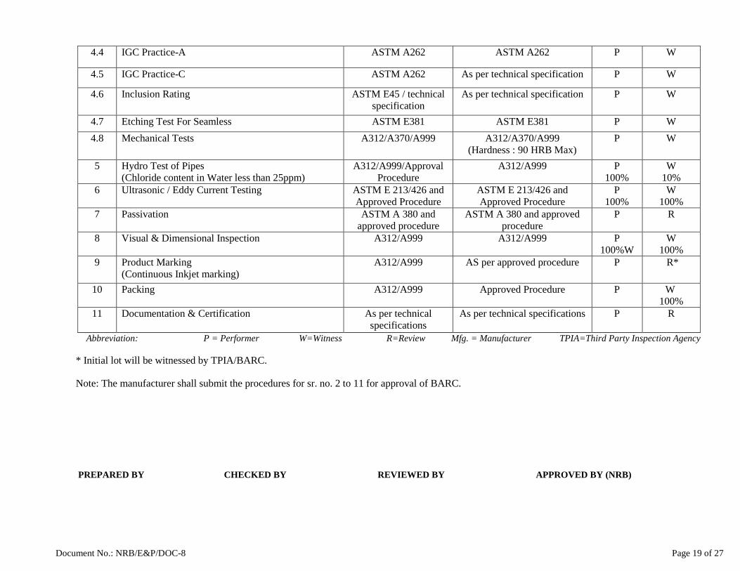
Document No.: NRB/E&P/DOC-8 Page 19 of 27
Abbreviation: P = Performer W=Witness R=Review Mfg. = Manufacturer TPIA=Third Party Inspection Agency
* Initial lot will be witnessed by TPIA/BARC.
Note: The manufacturer shall submit the procedures for sr. no. 2 to 11 for approval of BARC.
PREPARED BY CHECKED BY REVIEWED BY APPROVED BY (NRB)
4.4 IGC Practice-A ASTM A262 ASTM A262 P W
4.5 IGC Practice-C ASTM A262 As per technical specification P W
4.6 Inclusion Rating ASTM E45 / technical specification
As per technical specification P W
4.7 Etching Test For Seamless ASTM E381 ASTM E381 P W 4.8 Mechanical Tests A312/A370/A999 A312/A370/A999
(Hardness : 90 HRB Max) P W
5 Hydro Test of Pipes (Chloride content in Water less than 25ppm)
A312/A999/Approval Procedure
A312/A999 P 100%
W 10%
6 Ultrasonic / Eddy Current Testing ASTM E 213/426 and Approved Procedure
ASTM E 213/426 and Approved Procedure
P 100%
W 100%
7 Passivation ASTM A 380 and approved procedure
ASTM A 380 and approved procedure
P R
8 Visual & Dimensional Inspection A312/A999 A312/A999 P 100%W
W 100%
9 Product Marking (Continuous Inkjet marking)
A312/A999 AS per approved procedure P R*
10 Packing A312/A999 Approved Procedure P W 100%
11 Documentation & Certification As per technical specifications
As per technical specifications P R

Document No.: NRB/E&P/DOC-8 Page 20 of 27
Annexure-VII Procedure for Automatic Ultrasonic Testing (AUT)
Procedure No.: Date :
1. Scope :
This procedure is applicable to carry out Ultrasonic testing for detection of planer, longitudinal and circumferential discontinuities in SS seamless pipes by Ultrasonic immersion technique.
2. References:
ASTM E 213 ASTMA 312 ASTM A 578/ A 577 ASTM A 999 ASME Section V Tender Technical specification
3. Personnel qualification
The test shall be conducted by UT Level-1 qualified person. The interpretation and evaluation shall be done by UT Level-II qualified personnel. Personnel shall be qualified as per SNT-TC-1A. Personnel should be certified by ISNT/ASNT.
4. Test method:
Immersion technique using pulse echo method shall be employed for straight beam and angle beam testing.
5. Surface Condition:
Surface to be inspected shall be free of dust, scale, dirt and other foreign materials that may interfere with the probe movement and with the interpretation of the result.
6. Equipment & Apparatus:
The pipe shall be tested by immersion testing system of reputed make. Immersion ultrasonic testing with pipe traveling spirally and probe stationary and / or probe rotating and pipe travel linearly either of two systems can be used for pipe testing.
7. Probes:
Line focused transducers of 5 MHz or more frequency – 02 nos. for circumferential scanning and 02 nos. of probe for longitudinal scanning are used. Additionally, 02 nos. of probes can be used for planner type discontinuity or pipes can be passed second time for detection of planner type discontinuity.
8. Couplant:
D. M. Water shall be used as couplant.
9. Equipment calibration:
The proper functioning of the examination of equipment shall be checked and the equipment shall be calibrated by the use of the reference specimen as minimum,
9.1 At the beginning and at the end of each production run of a given size and thickness of a given material 9.2 After each 4 hours or less during the production run. 9.3 Every time machine/reference parameters are changes.
9.4 At any time malfunctioning is suspected. In case of non-conformance of calibration each product that has been tested since last valid calibration shall be re-examined.
9.5 Equipment shall be calibrated every year for Screen Height and time base linearity.
10. Reference standard:
10.1 The reference notches shall be made on the pipes of same material specification, diameter and wall thickness. 10.2 Notches are of ‘V’ type shape for angle beam testing.

Document No.: NRB/E&P/DOC-8 Page 21 of 27
10.3 100% area shall be examined for planer, longitudinal and circumferential flaws. 10.4 Notch dimensions:
Length Width Notch Depth
25 mm Proportional to depth of 60 degree V notch.
5% of nominal wall thickness or 0.1 mm whichever is higher
Tolerance on notch shall be as per E 213. Reference pipe shall contain four type of notches i.e. longitudinal internal, longitudinal external, circumferential internal and circumferential external.
Before starting the testing of pipe, calibration shall be done with the reference tubes.
11. Circumferential Scanning (for Longitudinal notch)
11.1 Normalization shall be done by focusing the sound beam to the axis of the pipe & obtaining maximum echo from the pipe surface.
11.2 After normalization the probe, it is offset from the centerline by 1/6 th of the outside diameter of the pipe to get the 19 deg. Angle of incidence and subsequently to get 45-deg. transmitted angle.
11.3 Then on OD Notch is brought near the probe and the height of the echo corning from the notch after ultrasonic beam travel inside the pipe wall & hits it, one skip distance is observed and the height is adjusted to 80% of FSH.
11.4 Similarly height of the echo coming from 1.0 notch is also picked up. LD notch is picked up at ½ skip distance. Necessary adjustments are made to get the echoes of almost equal height from the internal & external notches.
11.5 If they are unequal, lowest of the echo is taken as the reject level & alarm shall be set to that level. Range should be selected so echo from notches (OD & ID) are separated sufficiently on CRT.
11.6 Pass the calibration Pipe 4 to 5 times & the signals from notches shall be observed. 11.7 Carry out calibration for two probes so that the sound beams for two probes are in two opposite directions
(Clockwise & anticlockwise). 12. Axial Scanning (for Circumferential notch)
12.1 Normalization shall be done by focusing the sound beam to the axis of the pipe & obtaining maximum echo
from the pipe surface.
12.2 After normalizing the probe, it is turned to 19 deg. to get 45 deg. transmitted angle. Two probes are set in
such a way both forward & reverse scanning can be done simultaneously.
12.3 Necessary adjustments are made as in case of longitudinal calibration to get echoes of almost equal height
from the internal & external notches. lf they are unequal, lowest of the two echoes shall be taken as the reject
level & alarm shall be set to that level. Reference level shall be set 80% FSH.
12.4 After calibration is done gain setting (dB), reject level etc. shall be noted and they shall not be disturbed
throughout the testing.
13. Normal beam scanning:
For straight beam testing, back surface reflection technique or multiple reflections technique (if required) sl1all he used to detect planner type discontinuity.
14. Equipment setting:
14.1 Setting up of calibration and verification by level – II personnel.
14.2 Testing shall be carried out at the same gain, which is used to pick up defect notches.
14.3 Pipes to be tested are free from dust scale grease & foreign material that may give spurious signals.

Document No.: NRB/E&P/DOC-8 Page 22 of 27
14.4 Testing shall be done with four transducers for detecting longitudinal & circumferential discontinuities in
pipes in two opposite directions.
14.5 Pipes shall be reasonably straight before feeding for ultrasonic examination.
14.6 Untested length shall be cut after testing.
15. Acceptance criteria
A. For angle bean technique
15.1 The defect that are giving signals of height equal to or more that of the standard notch signals are subject to
non-conformance.
15.2 Part of the pipes with unacceptable signals shall be rectified without affecting minimum wall thickness &
retested.
B. For straight beam testing
15.3 Any area where discontinuities produce a continuous loss of back reflection is unacceptable. 15.4 Any kind of discontinuity indication is unacceptable.
Non-conforming pipes shall be marked at ends with color paint & kept in separate collectors.
16. Post cleaning
Pipe shall be cleaned thoroughly by rinsing water and then cleaned by pressurized water jet to remove dust, dirt and oil article.
17. Report:
Results & parameters shall be recorded in “Auto Ultrasonic Test Report”
Manufacturer QA, NRB
************************

Document No.: NRB/E&P/DOC-8 Page 23 of 27
Procedure for Manual Ultrasonic Testing (MUT)
1. Scope :
This procedure is applicable to carry out Ultrasonic testing for detection of planer, longitudinal and circumferential discontinuities in SS seamless pipes by contact method.
2. References:
ASTM E 213 ASTMA 312 ASTM A 578/ A 577 ASTM A 999 ASME Section V Tender Technical specification
3. Personnel qualification
The test shall be conducted by UT Level-1 qualified person. The interpretation and evaluation shall be done by UT Level-II qualified personnel. Personnel shall be qualified as per SNT-TC-1A. Personnel should be certified by ISNT/ASNT.
4. Test method:
The Pipe shall be examined ultrasonically by straight beam and angle beam with Pulse Echo Contact method. 5. Surface Condition:
Surface to be inspected shall be free of dust, scale, dirt and other foreign materials that may interfere with the probe movement and with the interpretation of the result.
6. Equipment & Apparatus:
A. Ultrasonic Flaw Detector
The UT instrument shall be of Pulse echo type with A-Scan presentation. The pipe shall be tested by immersion testing system of reputed make.
B. Probes:
Shear wave probe shall be in the range from 45° to 70° and effective crustal area shall be in the range from 20 mm2 to 625 mm2. Shear wave prove of 8x9 mm or 20 x 22 mm shall be used. T-R probe shall have diameter of 10mm / 24 mm. Probes shall be longitudinally and transversally contoured for scanning convex surface, when the diameter of the test object is below ten times the length of probe shoe. Transduce Frequency shall be 4 MHz or higher.
7. Couplant: 7.1 Light machine Oil or water shall be used as a couplant. The same type of couplant shall be used for
calibration, setting sensitivity, scanning and defect assessment. 7.2 Chloride & Sulphur content of couplant should not exceed 25 ppm. 7.3 After completion of the examination, the couplant shall be removed if its presence could adversely affect later
manufacturing or inspection operations or the integrity of the components.
8. Equipment calibration:
8.1 The proper functioning of the examination of equipment shall be checked and the equipment shall be calibrated by the use of the reference specimen as minimum,
8.2 At the beginning and at the end of each examination of a given size and thickness of a given material 8.3 At least every 4 hrs during examination. 8.4 Every time machine/reference parameters are changes. 8.5 At any time malfunctioning is suspected. In case of non-conformance of calibration each product that has
been tested since last valid calibration shall be re-examined.

Document No.: NRB/E&P/DOC-8 Page 24 of 27
8.6 Equipment shall be calibrated every year for Screen Height and time base linearity. 9. Calibration setting/Reference Standard: 9.1 The reference notches shall be made on the pipes of same material specification, diameter and wall thickness. 9.2 DAC shall be prepared using 60 deg. V-Notch for longitudinal and circumferential scanning. 9.3 For straight beam testing, back surface reflection technique of multiple reelection technique (if required) shall
be used to detect planner type discontinuity. 9.4 100% area shall be examined for planer, longitudinal and circumferential flaws. 9.5 Notch dimensions:
Length Width Notch Depth
25 mm Proportional to depth of 60 degree V notch.
5% of nominal wall thickness or 0.1 mm whichever is higher
Tolerance on notch shall be as per E 213. Reference pipe shall contain four type of notches i.e. longitudinal internal, longitudinal external, circumferential internal and circumferential external. Before starting the testing of pipe, calibration shall be done with the reference tubes.
10. Circumferential Scanning (For Longitudinal Notch)
10.1 ID notch is brought near the probe and the height of the echo coming from the notch after ultrasonic beam travel inside the pipe wall & hits it, ½ skip distance and the height is adjusted to 80% of FSH.
10.2 Mark the height of signals amplitude on the CRT Screen. 10.3 Record gain and do not change the gain. 10.4 Similarly height of the echo coming from O.D. notch is also picked up. OD notch is picked up at one skip
distance. 10.5 Mark the height of signal amplitude on the screen. 10.6 Also mark the signal height from one and half skip distance. 10.7 Connect the marked point on the screen. 10.8 Marked DAC shall be used as reference for discontinuity evaluation. 10.9 Range should be selected so as echo from OD & ID notches are separated sufficiently on CRT.
11. Axial Scanning ( For Circumferential scanning)
11.1 Same steps shall be followed as per previous clause to calibrate the machine for circumferential Notch. 11.2 DAC shall be prepared and used as reference for discontinuity evaluation. 11.3 Record the gain. 11.4 After calibration is done gain setting (dB), reject level etc. shall be noted and they shall not disturb throughout
the testing.
12. Straight Beam Scanning :
12.1 Place T-R probe on the surface of the pipe. 12.2 Bring first back surface reelection to 100% full screen height by increasing or decreasing gain. 12.3 Record the gain. 12.4 Add +6 dB for scanning. 13. Equipment setting & Sensitivity: 13.1 Setting up of calibration and verification by level – II personnel. 13.2 Testing shall be carried out at the same gain, which is used to pick up defect notches. 13.3 Scanning shall be performed at a gain recorded during notch detection and with (+6dB) additional. 13.4 Evaluation shall be done by reducing 6dB. 13.5 Scan all sections of pipes in four directions, clock-wise and anti-clockwise and forward and reverse direction
from the outer diameter of the pipes. 13.6 Scanning speed shall not exceed 15mm/s.

Document No.: NRB/E&P/DOC-8 Page 25 of 27
13.7 100% scanning coverage shall be performed over the surfaces by overlapping consecutive probe traverses by at least 10% of the effective probe diameter.
14. Acceptance criteria For Angle Beam: Any discontinuity signal exceeding the DAC shall be cause of rejection for angular scanning. Part of the pipes with unacceptable signals shall be rectified without affecting minimum wall thickness & retested. For Straight Beam: All indications that are equal to or greater than the rejection level established during calibration shall be considered unacceptable. Non-conforming pipes shall be marked at ends with red paint & kept in separate collectors.
15. Post cleaning Pipe shall be cleaned thoroughly by rinsing water and then cleaned by pressurized water jet to remove dust, dirt and oil particle.
16. Report: The report shall include at least the following information: a. Identification of the material, type, size, lot, heat. b. Identification of the examination equipment and accessories. c. Name & Qualifications of UT operator and reviewing Engineer. d. Details of examination technique, including examination speed and testing frequency. e. Description of the calibration standard with sketches, including the actual (measured) Dimensions of the
artificial discontinuities. f. Description of the di stance-amplitude correction procedure if use Examination results and method of
eliminating defects. g. Calibration data and examination results shall be provided. Manufacturer QA, NRB
************************
Document No.: NRB/E&P/DOC-8 Page 26 of 27
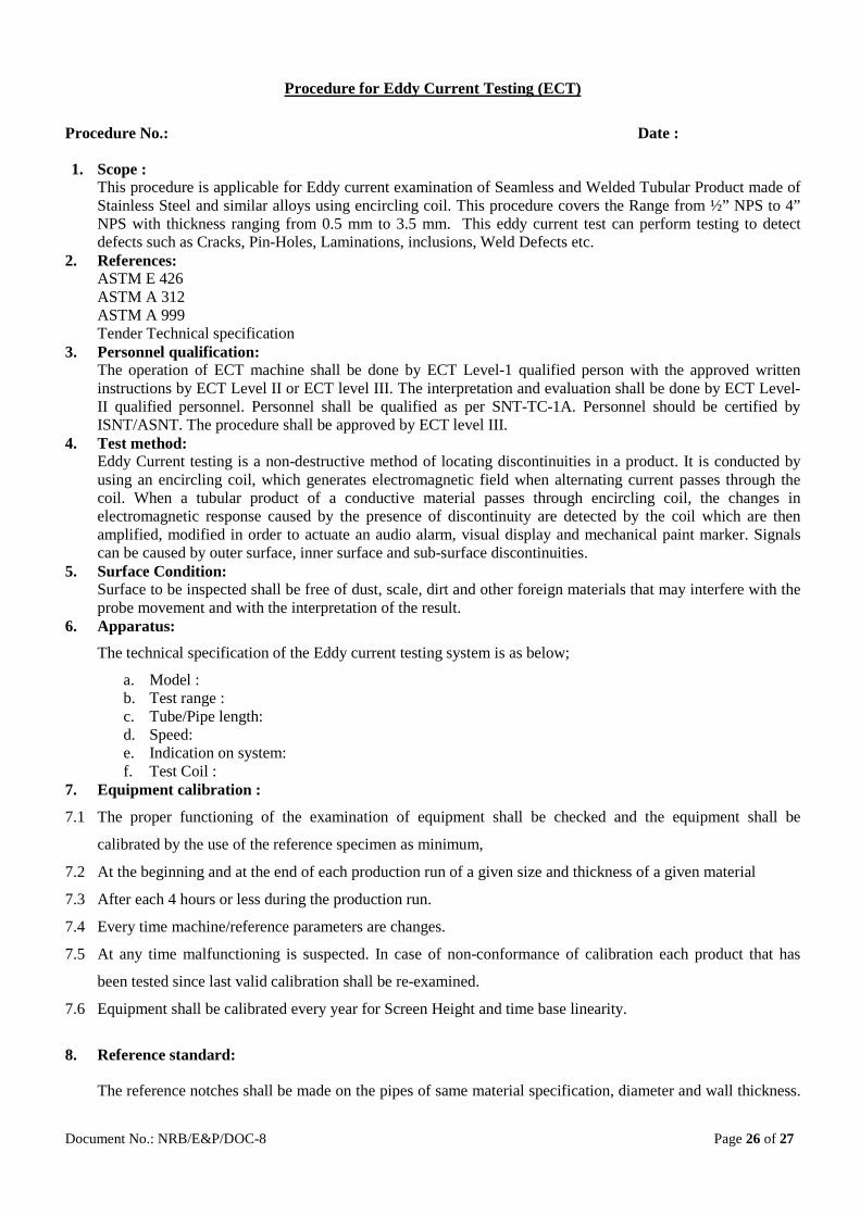
Procedure for Eddy Current Testing (ECT)
Procedure No.: Date :
1. Scope : This procedure is applicable for Eddy current examination of Seamless and Welded Tubular Product made of Stainless Steel and similar alloys using encircling coil. This procedure covers the Range from ½” NPS to 4” NPS with thickness ranging from 0.5 mm to 3.5 mm. This eddy current test can perform testing to detect defects such as Cracks, Pin-Holes, Laminations, inclusions, Weld Defects etc.
2. References: ASTM E 426 ASTM A 312 ASTM A 999 Tender Technical specification
3. Personnel qualification: The operation of ECT machine shall be done by ECT Level-1 qualified person with the approved written instructions by ECT Level II or ECT level III. The interpretation and evaluation shall be done by ECT Level-II qualified personnel. Personnel shall be qualified as per SNT-TC-1A. Personnel should be certified by ISNT/ASNT. The procedure shall be approved by ECT level III.
4. Test method: Eddy Current testing is a non-destructive method of locating discontinuities in a product. It is conducted by using an encircling coil, which generates electromagnetic field when alternating current passes through the coil. When a tubular product of a conductive material passes through encircling coil, the changes in electromagnetic response caused by the presence of discontinuity are detected by the coil which are then amplified, modified in order to actuate an audio alarm, visual display and mechanical paint marker. Signals can be caused by outer surface, inner surface and sub-surface discontinuities.
5. Surface Condition: Surface to be inspected shall be free of dust, scale, dirt and other foreign materials that may interfere with the probe movement and with the interpretation of the result.
6. Apparatus:
The technical specification of the Eddy current testing system is as below;
a. Model : b. Test range : c. Tube/Pipe length: d. Speed: e. Indication on system: f. Test Coil :
7. Equipment calibration :
7.1 The proper functioning of the examination of equipment shall be checked and the equipment shall be
calibrated by the use of the reference specimen as minimum,
7.2 At the beginning and at the end of each production run of a given size and thickness of a given material
7.3 After each 4 hours or less during the production run.
7.4 Every time machine/reference parameters are changes.
7.5 At any time malfunctioning is suspected. In case of non-conformance of calibration each product that has
been tested since last valid calibration shall be re-examined.
7.6 Equipment shall be calibrated every year for Screen Height and time base linearity.
8. Reference standard:
The reference notches shall be made on the pipes of same material specification, diameter and wall thickness.

Document No.: NRB/E&P/DOC-8 Page 27 of 27
Notches shall be of ‘V’ type shape for angle beam testing.
Notch dimensions:
Length Width Notch Depth
25 mm Proportional to depth of 60 degree V notch.
5% of nominal wall thickness or 0.1 mm whichever is higher
Reference pipe shall contain four type of notches i.e. longitudinal internal, longitudinal external, circumferential internal and circumferential external.
Before starting the testing of pipe, calibration shall be done with the reference tubes.
9. Procedure :
9.1 After standardization of the apparatus the reference standard is once again allowed to pass through the system
and the results are observed. This shall be repeated at to ensure the consistency of result over audio, visual
and paint marking indication.
9.2 If the results are consistent then each pipes from the lot is allowed to pass through the system and the results
are obtained and compared with the reference standard pipe.
9.3 The test apparatus shall be standardized at the beginning and end of each lit of pipes, change in test system
setting, change of operator, equipment repair, interruption due to power loss, intervals of four hours during
examination and 20pipes whichever is less.
9.4 If upon any standardization, improper functioning is found, reset and re-standardized the apparatus and re-
examine all the pipes examined during period since last successful standardization.
9.5 The untested portion (determined by special reference standard) shall be cut from both the ends of the pipe.
10. Evaluation of imperfections:
10.1 Tubular producing a test signal below than lowest signal produced by the reference standard shall be accepted
and tubular producing a test signal equal to or greater than the lowest signal produced by the reference
standard shall be rejected.
10.2 The rejected tube shall be clearly marked, identified and separated from the accepted tubular product.
11. Report:
11.1 The manufacturer shall furnish a test report certifying that the material was tested in accordance with the
specification and fulfills the requirement designated in the order.
11.2 The test report shall include manufacturer's name, customer's name, Purchase order no., date of test
performed, size of tubular tested, specification and grade of the material, heat no, test parameters and test
results.
11.3 Report of each pipe/tube shall be prepared separately with its graphical inspection record printout.
Manufacturer QA, NRB
************************