technical specification for - · pdf filetechnical specification for line & erection ....
TRANSCRIPT
VOL-II(TS) E14-LINE & ERECTION PAGE 1/ 20
CHAPTER – E14
TECHNICAL SPECIFICATION
FOR
LINE & ERECTION

VOL-II(TS) E14-LINE & ERECTION PAGE 2/ 20
TABLE OF CONTENTS
OF
LINE & ERECTION
NO DESCRIPTION PAGE NO
1.0 General 3
2.0 Survey 3
3.0 Check Survey 5
4.0 Pole Fixture And Accessories 5
5.0 Stringing And Installation Of Line With Conductors 6
6.0 Way-Leave And Tree Cutting 9
7.0 Conductor 10
8.0 Poles 10
9.0 Erection Work 10
10.0 Drawings For Foundations 10
11.0 Construction Of Foundation Fo H Pole, 11
12.0 Earthing Of Support 12
13.0 Fixing Of Cross Arms 13
14.0 Installation Of Line Materials 14
15.0 Handling Of Conductor 14
16.0 Stringing Of Conductor 14
17.0 Flexible Copper Bond 15
18.0 Taking Over 16
19.0 Materials Handling And Insurance 16
20.0 Check List 17
21.0 TS of GI Wire 6SWG & 8SWG 17
22.0 TS of Eye Bolt for Guarding 18
23.0 TS of Aluminium Binding Wire 19

VOL-II(TS) E14-LINE & ERECTION PAGE 3/ 20
TECHNICAL SPECIFICATION FOR CONSTRUCTION OF
33 KV LINES AND 11KV LINES & USING H POLES
1.0 GENERAL:
The work covered by this Specification is for construction 33kV and 11kV
distribution lines using NBLS towers, H pole, Joist poles and PSC poles.The H
poles shall be constructed by joing two channels (200 X 75 X 7.5) face to face by
means of 200 X 270 mm, 6 mm thick plate at a spacing of 900mm c/c.
The Right of way shall be solved by the contractor and all expenses there of shall
be borne by him. However, Owner shall render all helps in co-ordination with the
local administration for solving the same. Involvement of Forest land should be
restricted as far as possible.
2.0 SURVEY (detail survey, spotting of Poles & estimating of quantities ):
2.1 Preliminary investigations have been made. The topography of all 33 kV lines
and 11kV lines of more than 5km length have been uploaded in
www.optcl.co.in.
Detailed survey shall be carried out by the contractor to confirm the Route
alignment for the lines. If the line is passing in any Municipal/ NAC areas
permission from local bodies has to be obtained prior to execution of work.
Suitable distance from the side of the road has to be made towards placement
of line poles.
2.2 Provisional quantities/numbers of different types poles have been estimated
and indicated in the BOQ Schedule given. However, final quantities for work
shall be as determined by the successful bidder, on completion of the detail
survey, profile plotting.
2.3 The contractor shall undertake detailed survey on the basis of the tentative
alignment fixed by the Owner. The said preliminary alignment may, however,
change in the interest of economy to avoid forest and hazards in work. While
surveying the alternative route the following points shall be taken care by the
contractor.
(a) The line is as near as possible to the available roads in the area.
(b) The route is straight and short as far as possible.
(c) Good farming areas, religious places, forest, civil and defense
installations, aerodromes, public and private premises, ponds, tanks,
lakes, gardens, and plantations are avoided as far as practicable.
(d) The line should be far away from telecommunication lines as
reasonably possible. Parallelism with these lines shall be avoided as far
as practicable.
(e) Crossing with permanent objects are minimum but where unavoidable
preferably at right angles.
(f) Difficult and unsafe approaches are avoided.
(g) The survey shall be conducted along the approved alignment only.
VOL-II(TS) E14-LINE & ERECTION PAGE 4/ 20
(h) For river crossing/ Crossing of Nallas: Taking levels at 5 meter interval
on bank of river and at 20 meter interval at bed of river so far as to
show the true profile of the ground and river bed railway/road bridge,
road The levels shall be taken at least 100 m. on either side of the
crossing alignment.Both longitudinal and cross sectional shall be drawn
preferably to a scale of 1:2000 at horizontal and 1:200 vertical.
After completing the detailed survey in accordance to the relevant IS, the
contractor shall submit the final profile (in case of 33kV lines and only crossings of
11kV lines) and pole schedule (with no. of stay or strut) for final approval of the
Owner. To facilitate checking of the alignment, suitable reference marks shall be
provided. For this purpose, concrete pillars of suitable sizes shall be planted at all
angle locations and suitable wooden/iron pegs shall be driven firmly at the
intermediate points. The contractor shall quote his rate covering these involved
jobs.
2.4 Optimization of Pole Location
2.4.1 Pole Spotting
To optimize the line length, the contractor shall spot the poles in such a way
so that the line is as close as possible to the straight line drawn between the
start & end point of the line.
2.4.2 Road Crossings:- At all road crossings, the GI 13 mtr JOIST DP shall be
used. There should absolutely be no joints in the conductors in all road, power
line and all other major crossing. The ground clearance from the road
surfaces under maximum sag condition shall be not less than 8.5mtr over
roads. In National High way the minimum height of guarding at the maximum
sagging point should be less than 8.5 mts.
2.4.3 Railway Crossings- The railway crossing shall be carried out with
underground cables in the manner as approved & prescribed by the railway
authorities from time to time, preferably by HDD method using HDPE pipes .
The crossing length is mentioned in the Price Schedule. In case of quantity
variation during execution, payment will be done for actual work done on
prorate basis.
During detailed engineering, the contractor shall prepare & submit the
proposed arrangement for each railway crossing to the Owner alongwith all
documents drawings etc as per the requirements The approval for crossing
railway track shall be obtained by the owner from the Railway Authority.
2.4.4 Power Line Crossings-
Where the line is to cross over another line of the same voltage or lower
voltage, provisions to prevent the possibility of their coming into contact with
each shall be made in accordance with the Indian Electricity Rules.
2.5 Details En-route
After survey and finalization of route, the contractor shall submit detailed route
map for each line. This would be including following details:

VOL-II(TS) E14-LINE & ERECTION PAGE 5/ 20
All poless on both sides of the power line, road crossings shall be tension
poles i.e. disc type insulators shall be used on these poles. At all the crossing
described above the contractor shall use protective guarding as per REC
Construction Standard A-1 and M-6 to fulfill statutory requirements for 11kV &
33KV line using H poles. In case of 11kV & 33 KV line in the village,
protective guarding shall be used wherever it will be required.
Clearance from Ground, Building, Trees etc. – Clearance from ground,
buildings, trees and telephone lines shall be provided in conformity with the
Indian Electricity Rules, 1956 as amended up to date. The contractorshall
select the height of the poles in order to achieve the prescribed electrical
clearances.
2.5. Final Schedule
The final schedule including Bill of quantity indicating location of poles
specifically marking locations of failure containment pole/structure, line tapping
points; angle of deviation at various tension pole locations, all type of
crossings and other details shall be submitted for the approval of the owner.
After approval, the contractor shall submit six more sets of the approved
documents along with one soft copy in CD to OWNER for record purpose.
3.0 CHECK SURVEY
The contractor shall undertake the check survey during execution on the basis
of the alignment profile drawing and pole schedule approved by the Owner. If
during check survey necessity arises for minor change in route to eliminate
way leave or other unavoidable constraints, the contractor may change the
said alignment after obtaining prior approval from the Owner.
4.0 POLE FIXTURE AND ACCESSORIES
4.1 Danger Plates & Number Plates
The contractor shall provide & install danger plates on all 33kV, 11kV DP
structures, Single pole structures. The dimension of the plate size: Length
250mm X Width 200mm, Thickness (without enameling) - 2mm, Thickness
(With enameling) - 2.3mm. Danger Boards shall conform to IS: 2551. For
details, Please refer to drawing no. ODASSP/LINE/15.
4.2 Anti-climbing Devices
The contractor shall provide and install anti-climbing device on all 33kv and
11 kV DP structures, 4-Pole structures, and at all single poles. This shall be
done with G.I. Barbed wire with spikes. The barbed wire shall conform to IS-
278 (Grade A1). The barbed wires shall be given chromatin dip as per
procedure laid down in IS: 1340.
4.3 Fittings Common to all Line
Pin Insulator Binding: The contractor shall use AL. Binding wire for binding
shall be as per REC Construction Standards No. C-5 or better thereof.
Mid Span Compression Joint & Repair Sleeves: The contractor shall supply &
install the Mid Span Compression Joint and Repair Sleeves as per IS: 2121
(Part II).
Guy/Stay wire Clamp: The contractor shall supply & install Guy/Stay wire
Clamp as per REC Construction Standard G-1 or better.

VOL-II(TS) E14-LINE & ERECTION PAGE 6/ 20
Strut (Stud) will be provided in all angle points with deviation more than 100
upto 600.
4.4 Stay/Guy Sets
a) The Stay/Guys shall be used at the following pole locations;
At all the tapping points & dead end poles.
At all the points as per REC construction dwg. No. A-10 ( for the diversion
angle of 10-60 degree)
Both side poles at all the crossing for road, nallaha, railway crossings etc.
b) The arrangement and number of stay sets to be installed on different pole
structures shall be as per REC Construction Standards no. A-23 to A-27,
G-5 & G-8. However, this shall be decided finally during erection, as per
the advice of Engineer.
c) The stay set to be installed complete in all respect and would broadly
consist of following items:
7/10 SWG G.I. Stay wire for 11 kV lines as per REC Specification
No.46/1986 Stay Insulator type C for 11 kV line as per REC Specification
No. 21/1981, Turn Buckle. Anchor rod and plate (Hot Dipped galvanized).
Thimbles and Guy Grip Complete stay set shall be as per REC
Construction Standards no. G-1. The stay clamp is envisaged as GS
structure along with other clamps brackets etc.
4.5. Erection of stay sets
The contractor shall install the stay set complete in all respect as per REC
Specification. This includes excavation of pit in all kinds of soil with PCC in the
ratio 1:2:4 as specified which shall be placed in the bottom of the pit.
The rest (upper half) of the pit shall be filled with excavated soil duly
compacted layer by layer. An angle between 30 to 45 degrees shall be
maintained between stay wire and the pole. The stay wire shall be used with a
stay insulator at a height of 5 mts. above ground level with F.I. turn buckle.
5.0. Stringing and Installation of Line with Conductors.
5.1 General
The scope of erection work shall include the cost of all labour, tools and plants
such as tension stringing equipment and all other incidental expenses in
connection with erection and stringing work. The Bidders shall indicate in the
offer the sets of stringing equipment he would deploy exclusively for work
under each package.
The stringing equipments shall be of sufficient capacity to string
AAA conductor or ACSR conductor.
The Contractor shall be responsible for transportation to site of all the
materials to be provided by the Contractor as well as proper storage,
insurance etc. at his own cost, till such time the erected line is taken over by
the owner.
Contractor shall set up required number of stores along the line and the exact
location of such stores shall be discussed and agreed upon with the Owner.
5.2 Insulator Fixing
Pin insulators shall be used on all poles while strain insulators shall be used
on all angle & dead end poles. Special type Pin Insulators should be used for
VOL-II(TS) E14-LINE & ERECTION PAGE 7/ 20
conductors more than 100 mm2. In coastal districts of Balasore, Bhadrak,
Jajpur, Kendrapara, Jagatsinghpur, Cuttack, Khurdha, Puri and Ganjam
polymer insulators shall be used. Damaged insulators and fittings, if any, shall
not be used. Prior to fixing, all insulators shall be cleaned in a manner that
shall not spoil, injure or scratch the surface of the insulator, but in no case
shall any oil be used for this purpose. Torque wrench shall be used for fixing
various line materials and components, such as suspension clamp for
conductor, whenever recommended by the manufacturer of the same.
5.3 Running Out of the Conductors
The contractor shall be entirely responsible for any damage to the pole or
conductors during stringing. The conductors shall be run out of the drums from
the top in order to avoid damage to conductor
A suitable braking device shall be provided to avoid damaging, loose running
out and kinking of the conductors. Care shall be taken to ensure that the
conductor does not touch and rub against the ground or objects, which could
scratch or damage the strands.
The sequence of running out shall be from the top to down i.e. the top
conductor shall be run out first, followed in succession by the side conductors.
Unbalanced loads on poles shall be avoided as far as possible.
Wherever applicable, inner phase off-line conductors shall be strung before
the stringing of the outer phases is taken up.
When lines being erected run parallel to existing energized power lines, the
Contractor shall take adequate safety precautions to protect personnel from
the potentially dangerous voltage build up due to electromagnetic and
electrostatic coupling in the pulling wire, conductors and earth wire during
stringing operations.
The Contractor shall also take adequate safety precautions to protect
personnel from potentially dangerous voltage build up due to distant electrical
storms or any other reason.
5.4 Repairs to Conductors
The conductor shall be continuously observed for loose or broken strands or
any other damage during the running out operations. Repair to conductors, if
necessary, shall be carried out with repair sleeves and not more than one
repair sleeve will be used in one span.
Repairing of the conductor surface shall be carried out free of cost only in
case of minor damage, scuff marks, etc. The final conductor surface shall be
clean, smooth and free from projections, sharp points, cuts, abrasions etc.
After compression the sharp edges must be smoothened by filing.
The Contractor shall be entirely responsible for any damage to the poles,
insulators etc during stringing.
5.5 Stringing of Conductor
The stringing of the conductor shall be done by the standard stringing method.
The Bidder shall submit complete details of the stringing method for owner‟s
approval. Conductors shall not be allowed to hang in the stringing blocks for
more than 96 hours before being pulled to the specified sag.

VOL-II(TS) E14-LINE & ERECTION PAGE 8/ 20
Derricks/ scaffoldings or other equivalent methods shall be used to ensure that
normal services are not interrupted and any property is not damaged during
stringing operations for roads, telecommunication lines, power lines and
railway lines. However, shut-down shall be obtained when working at
crossings of overhead power lines. The contractor shall make specific request
for the same to the owner.
5.6 Jointing
When approaching the end of a drum length at least three coils shall be left in
place when the stringing operations are stopped.These coils are to be
removed carefully, and if another length is required to be run out, a joint shall
be made as per the recommendations of the conductor manufacturer.
Conductor splices shall not crack or otherwise be susceptible to damage
during stringing operation. The Contractor shall use only such
equipment/methods during conductor stringing which ensures complete
compliance in this regard.
All the joints on the conductor shall be of compression type, in accordance
with the recommendations of the manufacturer, for which all necessary tools
and equipment like compressors, dies etc., shall be arranged by the
contractor. Each part of the joint shall be cleaned by wire brush till it is free of
rust or dirt, etc. This shall be properly greased with anti-corrosive compound if
recommended by the manufacturer, before the final compression is carried out
with the compressors.
All the joints or splices shall be made at least 30 meters away from the pole.
No joints or splices shall be made in spans crossing over main roads, railway
line and Small River spans. Not more than one joint per conductor per span
shall be allowed. The compression type fittings shall be of the self centering
type or care shall be taken to mark the conductors to indicate when the fitting
is centered properly.
During compression or splicing operation, the conductor shall be handled in
such a manner as to prevent lateral or vertical bearing against the dies. After
compressing the joint, the Aluminium sleeve shall have all corners rounded;
burrs and sharp edges removed and smoothened.
To avoid any damage to the joint, the contractor shall use a suitable protector
for mid span compression joints in case they are to be passed over pulley
blocks/aerial rollers. The pulley groove size shall be such that the joint along
with protection can be passed over it smoothly.
In case AAAC is used each press should over lap 25% of the previous press.
5.7 Tensioning and Sagging Operations:
The tensioning and sagging shall be done in accordance with the approved
stringing charts or sag tables.
The sag shall be checked in the first and the last section span for sections up
to eight spans and in one additional intermediate span for sections with more

VOL-II(TS) E14-LINE & ERECTION PAGE 9/ 20
than eight and sagging operations shall be carried out in calm weather when
rapid changes in temperature are not likely to occur.
5.8 Clipping In
Clipping of the conductors into position shall be done in accordance with the
manufacturer‟s recommendations. Jumpers at section shall be formed to
parabolic shape to ensure maximum clearance requirements. Pilot pin
insulator shall be used, if found necessary, to restrict jumper swing & to
ensure proper clearance to design values.
Fasteners in all fittings and accessories shall be secured in position. The
security clip shall be properly opened and sprung into position.
5.9 Fixing of Conductors Accessories
Conductor accessories supplied by the Contractor shall be installed by the
Contractor as per the design requirements and manufacturer‟s instructions.
While installing the conductor accessories, proper care shall be taken to
ensure that the surfaces are clean and smooth and that no damage occurs to
any part of the accessories or of the conductors.
5.10 Replacement:
If any replacements are to be effected after stringing and tensioning or during
maintenance e.g. replacement of cross arms, the conductor shall be suitably
tied to the pole at tension points or transferred to suitable roller pulleys at
suspension points.
6.0 WAY-LEAVE AND TREE CUTTING
Way-leave permission which may be required by the contractor shall be arranged
at his cost. While submitting final-survey report for approval, proposals for way-
leave right of way shall be submitted by the contractor. Owner may extend help
to get the permission within a reasonable time as mutually agreed upon for which
due notice shall be given by the contractor in such a way so that obtaining
permission from appropriate authority do not hinder the continued and smooth
progress of the work.
The contractor shall take necessary precaution to avoid damage to any ripe and
partially grown crops and in the case of unavoidable damage, the Owner shall be
informed and necessary compensation shall be paid by the contractor.
All the documents required for application to the statutory authorities must be
prepared by the contractor & submitted to the Owner for submission of the
application towards approval of Railway Crossing etc. However, the
responsibilities lie with the contractor to get the clearance.
Trimming of tree branches or cutting of a few trees en-route during survey is
within the scope of survey to be done by the contractor. Contractor shall arrange
for necessary way-leave and compensation in this regard. During erection of the
line, compensation for tree cutting, damage caused to crops, actual cutting and
falling of the trees including way-leave permission for such route clearance shall
be arranged by the contractor at his cost. The contractor will identify the number
of trees and detail of obstructions to be removed for erection of the line and
intimate the Owner well in advance in case of any help.
VOL-II(TS) E14-LINE & ERECTION PAGE 10/ 20
Other related works like construction of temporary approach roads, etc. as
required, shall be done by the contractor and the same will lie within the scope of
contractor‟s work and such cost shall be considered to be included in the rates
quoted by him.
7.0 CONDUCTOR
AAA Conductors of 100 Sq mm (7/4.26) AAAC will be used in 11KV lines and
that of 148 sq mm mm (19/3.15) AAAC will be used in 33KV lines. The
conductors shall withstand a temperature of 850 C .
7.1 CLEARANCE FROM GROUND, BUILDING, TREES ETC.
7.2 Clearance from ground, buildings, trees and telephone lines shall be provided
in conformity with the Indian Electricity Rules, 1956 as amended up to date.
The bidder shall select the height of the poles such that all electrical
clearances are maintained.
7.3 Guarding mesh shall be used in all electric line / telecom line / road / drain /
canal crossing and at all points as per statutory requirements. The bidder shall
provide & install anti climbing devices and danger plates on all poles. Where
there is no such provision in the existing line.
7.4 Pole accessories like danger plates, and number plates shall be provided as
per IS: 2551 Standard.
8.0 POLES
The total steel structures should be Galvanized with minimum zinc coating of
610 gms / Sq. Mts. Where 11mtr & 13mtr G.I Joist can not be transported to
the site, two pieces of galvanized G.I Joist with single joint in lines only will be
allowed, subject to OPTCL approval. For 11Mtr. Long, (6mtr + 5 mtr), (7mtr +
4mtr) and For 13mtr long (7mtr + 6 mtr), (8mtr + 5mtr) G.I Joist Pole are
permissible, using galvanized sections of plates of adequate size along with
required size GI bolt nuts & spring washers is to be adopted. The materials
must conform to IS: 800. All the test on materials and fabrication etc will be as
per the relevant Indian standards.
In different crossings the contractor shall take into consideration the prevailing
regulations of the respective authorities before finalizing type and location of
the structures. While carrying out survey work, the contractor has to collect all
relevant data, prepare and submit drawings in requisite number for obtaining
clearance from road, aviation, railways, river and forest authorities.
9.0 ERECTION WORK
When the survey is approved, the contractor shall submit to the Owner a
complete detail schedule of all materials to be used in the line. Size and length
of conductor etc. are also to be given in the list. This schedule is very essential
for finalizing the quantities of all line materials. The contractor shall furnish the
same.
10.0 DRAWINGS FOR FOUNDATIONS
Indicative drawings of PSC pole, H poles, DP structures, 4-Pole structures etc
with foundation have been provided by OWNER in the bid document. Other

VOL-II(TS) E14-LINE & ERECTION PAGE 11/ 20
drawings as per the requirement shall be submitted by the contractor for
approval by by the OWNER.
11.0 CONSTRUCTION OF FOUNDATION FOR POLES
The contractor shall provide all tools, plants, instruments, qualified
supervisory personnel, labour materials, any temporary workers,
consumables, and everything necessary, whether or not such items are
specifically stated herein, for completion of the project in accordance with
specification requirement. The excavation shall be done in accordance with
the design and drawing. This shall also includes, where ever required,
proper shoring shuttering to maintain excavations and also the furnishing,
erecting and maintaining of substantial barricades around excavated areas
and warning lamps at night for ensuring safety of lives and property.
Scope also includes dumping of excavated materials in regular heaps,
bunds, rip rap with regular slope as directed by Engineer-in-charge within
the lead specified and leveling the same so as to provide natural
drainage. Rock/soil excavated shall be stacked properly. All softer
materials shall be laid along the center of the herpes, the harder and
more weather resisting materials forming the casing on the sides and the
top. Rocks shall be stacked separately.
The area to be excavated /filled shall be cleared of trees, plants, stumps,
bush, vegetation rubbish etc. and other objectionable matter. If any roots
or stumps or trees are met during excavation, they shall be removed as
directed by Engineer-in-charge.
Normal Soil:
These shall include all kinds of soils containing Sand, Silt and small
pellets, which are removable by ordinary pick axes, shovel and spade
and which are not classified under hard soil or soft rock.
Hard and soft rock:
This shall include rock, boulders, shale, chalk, slate, hard mica, schist,
laetrile and all other materials which in the opinion of the Engineer-in-
charge is rock, does not need blasting and could be removed with picks,
hammer, craw bars, wedges and pneumatic breaking work. This shall
also include rock boulders not longer than one meter in any direction and
not more than 500 mm in any one of the other two directions.
Wet Soil
Where the subsoil water table is encountered within the range of after
a of depth of 1 mtr from ground level or where for a substantial
period water is logged for example paddy field.
Where soil at a foundation is of composite nature, classification will
be according to the type of soil, which is preponderant in the footing
and the rate for the same will apply for the composite foundation. The
decision of the OPTCL/Engineer-in charge shall be final and binding
with reference to classification of soils.
All surplus excavated soil along with left over gradients if any “should

VOL-II(TS) E14-LINE & ERECTION PAGE 12/ 20
beremoved from work site and dumped at any suitable place in such
a manner that the landowner will not object.
A thin layer of nearly 200mm of surplus earthy can be stacked over
the excavated pits for future compaction”.
Standard penetration test to be carried out for long line one in ten
support sites.
Back filling has to be done by borrowed earth if required.
All organic or other foreign materials shall be removed from back fill earth.
The earth shall be deposited in maximum 200mm. Layers, leveled and
watered and rammed properly before another layer is deposited.
The back filling should be such that enough moisture would be available for
curing of the concrete embedded. Sufficient water shall be poured over the
back filled earth for proper consolidation.
All surplus excavated soil shall be stacked around the legs. In case of wet
locations, de-watering, shoring and shuttering etc. if required shall be paid
for based on unit rates indicated. The actual quantity shall be as approved
by the Engineer-in charge. The shoring and shuttering is to be done by very
good quality planks and supports as approved by Engineer-in-charge.
12.0 CEMENT CONCRETE (PLAIN OR REINFORCED), STUB SETTING
GROUNDING AND BACK FILLING etc.
A) Materials
All materials whether to be consumed in the work or used temporarily shall
conform to relevant IS specification, unless stated otherwise, and shall be of
the best approved quality.
B) Cement
Cement to be used in the work under the contract shall generally conform to
IS:269/455-1989. Cement bags shall be stored by the contractor in a water
tight well ventilated store sheds on raised wooden platform (raised at least 150
mm above ground level) in such a manner as to prevent deterioration due to
moisture or intrusion of foreign matter. Cements to be used within three
months from the date of manufacture. Sub-standard or partly set cement shall
not be used and shall be removed from the site by the contractor at his cost .
C) Coarse Aggregates i.e Stone chips or stone ballast. For M15 & M20 concrete,
the aggregate will be in the ranges from 12mm to 20mm.size.
D) The back filling of locations should be done by using the excavated soil only in
layers (each layer should not be more than 500 mm) by putting water and
ramming by using wooden rammers. In no case stone of size more than 75mm
used for back filling.Back-filling has to be done 75mm above ground level or
as specified.
2. Curing of concrete should be done for 28 day continuously. Curing should not
be done within 24 Hours of concreting.
3. All the excess excavated materials and other unused materials from the
concreting site should be disposed of to a suitable site by the contractor.

VOL-II(TS) E14-LINE & ERECTION PAGE 13/ 20
a) Mixer (Running time-2 min.)
b) In case of hand mixing, 10% extra cement has to be provided.
Hand mixing should be done on GI sheet platform only.
c) Poking rod may be used for compacting concrete.
d) Use of vibrator for compacting is mandatory.
e) Clean water (free from saline and alkaline) should be used for concreting.
f) Aggregates (both coarse and fine) used should be free from foreign materials.
g) Shutters used should not be removed before 24hrs. of casting.
h) In case of black cotton soil borrowed earth (morum soil mixed with sand is
preferable) may be used for back filling.
i) Sufficient qty. of water should be sprinkled over backfilled earth and chimney
kept wet by using wet gunny bags.
13.0 ERECTION OF POLE, CONCRETING OF POLES AND COMPACTION OF
SOIL
Drawing for the excavation of pits, Foundation of soil is enclosed which are to
be adopted.
13.1 Following arrangement shall be adopted for proper erection of poles wherever
necessary and properly compacting of the soil around the base / foot of the
poles, under this package.
(a) Excavation has to done as per the drawing to the required depth and size.
After final excavation the pit should be dressed properly so that uneven
portion and loose soil should be removed before PCC (M-10) is laid. The base
footing concrete shall be RCC (M-20) in all DP and PCC (M-15) for all single
H pole as per drawing no. ODSSP/SS/22.PSC Pole drawing no.
ODSSP/LINE/3.
(b) The verticality and leveling of pole/structure should be done by the help of
plumbob or with theodolite and leveling instrument.
(c) Pole Base clits ( 65x65x6mm angles, 400mm long) to be provided over
the Lean concrete in case of H pole and Joist pole. For PSC pole, MS
base plates of 500 X 500 X 10 mm shall be used.
13.2 Pole erection
1. After proper alignment, placing of base concrete of required height. Again
the verticality and leveling should be checked.
2. The RCC pedestal concrete (M-20) is to be done by providing good quality of
shutters, so that there will no leakage of cement slurry during concreting. The
cooping height should be 450 mm/750 mm above the existing ground level in
urban area and in cultivated lands respectively. The top portion of the cooping
should be made tapered.
3. All the bolted joints should be tightened properly by providing suitable size
GI Bolt Nuts and Spring washers. After completion of erection works all the
bolts should be spot welded in order to avoid theft of members.
13.2.1 All the persons working on line shall wear safety helmet, safety belt and
safety shoes, Similarly all the persons working on ground shall wear safety
helmet and safety shoes.
13.2.2. If there is any LT/HT power line near the vicinity of pole erection, necessary
shutdown of the power line shall be obtained in writing from the concerned
VOL-II(TS) E14-LINE & ERECTION PAGE 14/ 20
Agency in order to avoid electrical hazards caused by accidental touching of
stay/Guy ropes with power line.
13.2.3.Safety precaution Safety shall be given utmost importance during stringing.
The following need to be ensured.
13.2.4 Safe working conditions shall be provided at the stringing site.
13.2.5 Full proof communication through walky- talkie / mobile phones shall be
used in order to avoid any damage to workmen or public on ground.
13.2.6 The poles shall then be lifted to the pit with the help of wooden supports. The
pole shall then be kept in the vertical position with the help of 25 mm (min.)
manila ropes, which will act as the temporary anchor. The verticality of the
pole shall be checked by spirit level in both longitudinal & transverse
directions. The temporary anchor shall be removed only when poles set
properly in the pit for foundation concreting & backfilling with proper
compacting the soil. The backfilling should be done inlayers (maxm. 0.5
mts at a time with sprinkling of water and by using wooden hammer. No
stone more than 75 mm should be used during back filling.
13.2.7 Pin type insulators in all straight line locations and Four pair bolted type
tension H/W fittings in all DP structures shall be used in all new 33kV with 70
KN & 11 kV lines with 70 KN normal B&S insulators.
14.0. Earthing of Support
14.1 Each pole shall be earthed with coil type earthing as per REC Construction
Standard J-1.
14.2 All DP & Four pole structures & the poles on both sides of railway and road
crossing shall be earthed by providing two nos. pipe earthing as per Drawing
provided by OWNER.
15.0 Fixing of Cross Arms
After the erection of supports and providing guys, the cross-arms are to be
mounted on the support with necessary clamps, bolts and nuts. The practice
of fixing the cross arms before the pole erection should be followed.
16.0 INSTALLATION OF LINE MATERIALS
16.1 Insulator and Bindings- These materials are to be procured from the
approved contractors only after type test subsequent to the design approval of
OWNER.
1. In angle locations single tension fittings to be used with 4 nos. 70 KN disc
insulators for 33kV lines & 2nos. of 70KN disc insulators for 11kV lines.
3. Suitable pre formed armoured rods should be used in all suspension fittings in
case of higher size Conductors.
4. Guarding has to be provided at all road crossings .
5. Four pair bolted type (suitable for M-16 bolts) tension fittings for
AAA conductors and for River crossing locations, compression type tension
fittings for AAAC conductors has to be used.
6. The “distribution tie “ meant for pin insulator binding should be of no. 6 size
and that of soft annealed wire having a minimum length of 3 mtr.
7. Compression type jointing sleeves should be used for jointing of conductors
only.

VOL-II(TS) E14-LINE & ERECTION PAGE 15/ 20
16.2 Insulator hoisting
a) Insulators shall be completely cleaned with soft and clean cloth.
b) It shall be verified that there is no crack or any other damage to insulators.
c) It is very important to ensure that „R‟ clips in insulator caps are fixed properly.
This is a security measure to avoid disconnection of insulator discs.
d) Both Arcing horns (both at top & bottom) of each insulators string has to be
provided.
The pins for insulators shall be fixed in the holes provided in the cross-arms
and the pole top brackets. The insulators shall be mounted in their places over
the pins and tightened. In the case of strain or angle supports, where strain
fittings are provided for this purpose, one strap of the strain fittings is placed
over the cross-arm before placing the bolt in the hole of cross-arms. The nut of
the straps shall be so tightened that the strap can move freely in horizontal
direction.
All materials, which are to be supplied by the contractor should be procured
from the approved Manufactures of OWNER „s only. Procure ment from any
suppliers will not permitted. All the related drawings of materials has to be
approved by department. All the materials has to be tested in presence of
authorized representative of department as well as officers of third party
engaged by Government if any also.
17.0 Handling of Conductor
All cares should be taken not to damage conductor surface during transit.
Necessary tools and plants for the same has to be effectively used by the
agency.
17.1 Running Out of the Conductors:
The contractor shall be entirely responsible for any damage to the pole or
conductors during stringing. Care shall be taken that the conductors do not
touch and rub against the ground or objects, which could scratch or damage
the strands.
17.2 The sequence of running out shall be from the top to down i.e. the top
conductor shall be run out first, followed in succession by the side conductors.
Unbalanced loads on poles shall be avoided as far as possible. When lines
being erected run parallel to existing energized power lines, the Contractor
shall take adequate safety precautions to protect personnel from the
potentially dangerous condition.
17.3 Monitoring of Conductors during Stringing
a) The conductor shall be continuously observed for loose or broken strands or
any other damage during the running out operations. Repair to conductors, if
necessary, shall be carried out with repair sleeves.The final conductor surface
shall be clean, smooth and free from projections, sharp points, cuts,
abrasions, etc. The Contractor shall be entirely responsible for any damage to
the poles during stringing.
b) Conductor shall be checked constantly as it is unwound from Conductor drum
for any broken, damage or loose strand. If any major defect is noticed then the
defective portion has to be removed and mid span joint provided. However if

VOL-II(TS) E14-LINE & ERECTION PAGE 16/ 20
the defect is of minor nature i.e. number of damaged strands is not more than
1/6th of the total strands in outer layer, a repair sleeve shall be provided.
c) M.S.(mid span) Joint shall be provided at least 15 meters away from line
Poles/ Structures. All Mid-Span joints should be Compression type by
providing suitable aluminium compression pipes. The compression joints
should be continuous. In case of AAAC compression joints, minimum 25%
over lapping with the previous compression should be done.
d) There shall not be any Mid-Span joint over Rly / River / Main Road Crossing.
e) Not more than one Mid-Span Joint shall be provided in one span for each
conductor.
Rough sagged conductors of one phase shall be simultaneously tightened by
which machine fixed on pole till the desired final sag is achieved.
18.0 STRINGING OF CONDUCTOR
18.1 The works include spreading of conductors without any damage and stringing
with proper tension without any kinks/ damage Jumpering at cut points by
using two nos., three bolted, PG claps has to be done. No binding of two
conductors with aluminium wires will be allowed. In each and every joints
three bolted very good quality PG clamps should be used wrapping of suitable
aluminium tapes if required as per the decision of the Engineer in Charge. The
ground & line clearances at road crossings along roads other crossings shall
be as mentioned in this specification.( which also should not be less than the
relevant clearances mentioned in I.E. rules.)
18.2 While transporting conductors‟ drums to site, precautions are to be taken so
that the conductor does not get damaged. The drum shall be mounted on
cable drum support. The direction of rotation of the drum shall be according to
the mark in the drum so that the conductor could be drawn. While drawing the
conductor, it shall not rub against surface causing damage. The conductor
shall be passed over poles on rubberized or aluminum snatch block (pulley)
mounted on the poles for this purpose.
18.3 The conductor shall be pulled through come-along clamps to string the
conductor between the tension locations.
18.4 Conductor splices shall not crack or otherwise be susceptible to damage in the
stringing operation. The Contractor shall use only such equipment / methods
during conductor stringing which ensures complete compliance in this regard.
All the joints including mid span joints on the conductor shall be of the
compression type, in accordance with the recommendations of the
manufacturer.
The contractor shall remain fully responsible for the exact alignment of the
line. If after erection, any pole is found to be out of alignment, the same shall
have to be dismantled and re-erected after correction by the contractor at his
own cost, risk and responsibility, including installation of fresh foundation, if felt
necessary by the Owner.
NB:- 1.0 % is the non-accountable allowable wastage (for both sag & wastage)
will be permitted
19.0 TAKING OVER

VOL-II(TS) E14-LINE & ERECTION PAGE 17/ 20
Pole and Pole accessories received at site stores are to be stored item-wise
and mark-wise to facilitate joint inspection of the materials (with reference to
packing list and detailed order).
If the materials/equipment or any part thereof is damaged or lost during the
transit, the replacement of such materials shall be effected by the contractor
timely so as to maintain programme of work.
However, the line under erection shall be taken over by the purchaser only
when the entire line is completed in all respect and made ready for
commissioning at rated voltage. Partly erected line will not be taken over.
Taking over of the line shall be in no way relieve the contractor from his
responsibility for satisfactory operation of the erected line in terms of the
guarantee clause of the specification.
20.0 Check List
Before the line is offered for taking over and disbursement of final payment
subsequent to the materials reconciliations acomprehensive format in shape of
check list as shown at schedule C-4 must be filled upand signed by the executing
agency.
21.0 (A) TECHNICAL SPECIFICATIONS FOR GI WIRE (STAY WIRE)
II. SCOPE
This specification covers manufacture, testing and supply of hot dip
galvanized MS solid wire of sizes as specified in the GTP.
III. APPLICABLE STANDARDS
ZINC
Zinc shall conform to grade Zen 98 specified in IS 209& IS:4826-1979 with
upto date amendments.
ZINC COATING
Zinc coating shall be in accordance with IS:4826-1979 for heavily coated
hard quality.
GALVANISING
Galvanizing shall be as per IS:2629-1966, IS 4826-1979 with up to date
amendments.
UNIFORMITY OF ZINC COATING
Uniformity of zinc coating shall be as per IS:2633-1972 with up to date
amendments.
TENSILE PROPERTIES
The tensile strength of the wire after galvanizing shall be between
55-95 Kg/sq.mm ensuring MS wire mechanical properties as per IS-28:1972
8.1 to 8.3.
FREEDOM FROM DEFECTS
As per IS:2629-1966 & 4826-1979 & with up to date amendments be ensured.

VOL-II(TS) E14-LINE & ERECTION PAGE 18/ 20
IV. MATERIAL
The mild steel wire shall have chemical composition maximum sulphur-
0.055%, phosphorous -0.055%,Carbon 0.25%.
V. TESTS
During the process of manufacturer/fabrication and all tests for chemical,
mechanical, galvanizing as per IS- 280-1979, IS1521-1972, IS-1755-1961,
IS:6745-1972 & 4826-1979 shall be carried out. The certificate towards,
chemical composition shall be submitted for each lot offered for inspection.
The following tests shall be conducted in presence of the representative of the
Owner:
Visual physical inspection and measurement of specified dimension
Coating test as per IS:1755-1961, IS 2629-1966, IS:2633-1972, IS:4826-1969
Adhesion test as per IS:1755-1961,IS:2629-1966,IS:2633-1972,IS:4826-
1969,&IS:6745-1972
Tensile strength and breaking load and elongation determined as per IS:1521-
1972 with up to date amendments
VI. PACKING & MARKING
Packing shall be as per IS:280-1979 and each coil shall be between 50-100
kg.marking shall be as per IS:280-1972.
VII. GUARANTEED TECHNICAL PARTICULARS (GI WIRE 6 SWG & GI WIRE 8
SWG) is furnished at chapter -E24.
22.0 (B) TECHNICAL SPECIFICATIONS FOR EYE BOLT FOR GUARDING
GENERAL REQUIREMENTS:
1.M20 eye bolts (120 mm long) shall preferably be of drop forged manufacture
and shall be supplied complete with full thread and two full nuts.
2. Eye bolt shall be manufactured from steel to ISO 272, 885, 888, 4759/1 and
shall meet the requirements for mechanical properties detailed in ISO 272,
885, 888, 4759/1.
3. Where a welding process is used in manufacture, each eye bolt shall be
individually proof tested by the manufacture in accordance with ISO 272,
885, 888, 4759/1 to 125% of its safe working tensile load that is to 48kN.
The safe working tensile load shall be the ultimate axial tensile strength
divided by the factor of safety of 2.5.
4. The eye shall be permanently and legibly stamped with the letter METRIC in
letters not less than 3mm high. The safe working load of any eye bolt is that
load which may be safely carried in an axial direction. If loaded in any other
VOL-II(TS) E14-LINE & ERECTION PAGE 19/ 20
direction the safe working load is reduced and reference shall be made to
the following table for safe working load of M20 eye bolts and eye nuts.
23.0 (C) TECHNICAL SPECIFICATION FOR ALUMINIUM BINDING WIRE
I. SCOPE :
Scope covers manufacture, testing and supply of 3.53 mm dia Aluminium
Binding Wire as per IS 398.
II. MATERIALS :
The material comprising the wire shall have the following chemical
composition:
Aluminium 99.95% minimum Copper, silicon and iron 0.05% maximum
The surface of the wire shall be smooth and free from all irregularities and
imperfections. Its cross sections shall closely approximate that of true circle.
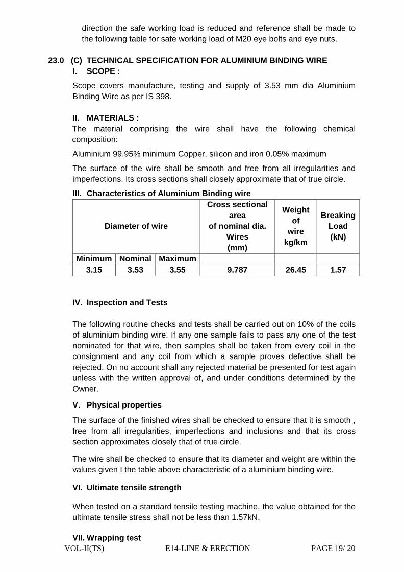
III. Characteristics of Aluminium Binding wire
Diameter of wire
Cross sectional
area
of nominal dia.
Wires
(mm)
Weight
of
wire
kg/km
Breaking
Load
(kN)
Minimum Nominal Maximum
3.15 3.53 3.55 9.787 26.45 1.57
IV. Inspection and Tests
The following routine checks and tests shall be carried out on 10% of the coils
of aluminium binding wire. If any one sample fails to pass any one of the test
nominated for that wire, then samples shall be taken from every coil in the
consignment and any coil from which a sample proves defective shall be
rejected. On no account shall any rejected material be presented for test again
unless with the written approval of, and under conditions determined by the
Owner.
V. Physical properties
The surface of the finished wires shall be checked to ensure that it is smooth ,
free from all irregularities, imperfections and inclusions and that its cross
section approximates closely that of true circle.
The wire shall be checked to ensure that its diameter and weight are within the
values given I the table above characteristic of a aluminium binding wire.
VI. Ultimate tensile strength
When tested on a standard tensile testing machine, the value obtained for the
ultimate tensile stress shall not be less than 1.57kN.
VII. Wrapping test

VOL-II(TS) E14-LINE & ERECTION PAGE 20/ 20
The wire shall withstand one cycle of a wrapping test as follows:
The wire shall be closely wrapped round a wire of its own diameter form a
close helix of eight turns. Six turns shall then be unwrapped and again closely
rewrapped in the same direction as the first wrapping. The wire shall not break
or crack when subjected to this test.
VIII. Packing & Delivery
The aluminium binding wire shall be delivered in 30m coils, with a permitted
tolerance of +5%.Random or non standard lengths shall not be permitted.
Each coil shall be adequately guarded against damage due to transportation
and handling and shall have an outer layer of tightly wound polythene tape or
be contained in a suitable, transparent plastic bag.
The internal diameter of the wound coil shall not be such as to result in a
permanent set in the conductor.
The coils shall be contained in non returnable wooden cases, with a gross
weight not in excess of 300 kg. The number of coils contained shall be marked
on the outside of each case.
IX. GUARANTEED TECHNICAL PARTICULARFS ALUMINIUM BINDING
WIRE is funnished at chapter E-24.
VOL-II(TS) E15- CIVIL WORKS FOR SUB-STATIONS PAGE-1 / 32
CHAPTER – E15
CIVIL WORKS
(Construction of Control
Room-cum- Swith gear room)

VOL-II(TS) E15- CIVIL WORKS FOR SUB-STATIONS PAGE-2 / 32
TABLE OF CONTENTS
OF
CIVILWORK FOR SUBSTATIONS
NO DESCRIPTION PAGE NO
1.0 Erection Work 3
2.0 Soil Investigation 4
3.0 Site Levelling 6
4.0 Site Drainage 7
5.0 Sewage System 8
6.0 Transformer Foundation, Rail Track 8
7.0 Fire Protection Walls 9
8.0 Boundary Wall/ Compound Wall 9
9.0 Cable Trenches 9
10.0 Foundation Design 10
11.0 Control Room and switch gear Building 15
12.0 Earthing 18
13.0 Wiring,Cabling and Cable Instalation 23
14.0 Laying and Installing of Cables 26
15.0 Supply Voltage 29
16.0 Erection Conditions 29
17.0 Contractor's field operation 29
18.0 Site Clearance 30
19.0 Materials and workmanship 31
VOL-II(TS) E15- CIVIL WORKS FOR SUB-STATIONS PAGE-3 / 32
TECHNICAL SPECIFICATION for CIVILWORK FOR SUBSTATIONS
1.0 ERECTION WORK
1.1 CIVIL WORKS
Civil works includes the following items:
The scope shall generally cover Construction of Control room-cum- Swith gear
room alongwith foundations. cable trenches along with covers, cable trench
crossings of road and rails, sump pits, marshalling box/control cubicle
foundations, switchyard dressing and levelling, site clearance, soil
investigation, roads, drains, fencing, gravel filling and, transformer
foundations, firewalls, control room building, Any other items, not specifically
mentioned here but required for the commissioning of substation shall be
deemed to be included in the scope of this Specification. The scope shall
further cover design, engineering, erection, testing and commissioning of all
civil works at each substation. All civil works shall also satisfy the General
Technical Clauses specified in other sections of this specification and as
detailed below.
Excavation, pile drilling, dewatering, carriage of excavated earth, plain cement
concrete (PCC), casting of reinforced cement concrete (RCC) foundations,
super-structures for sub- station structures, equipment supports, their control
cubicles, bus post supports, lighting poles and panels, brick and stone
masonry, cable trenches, pipe trenches with necessary pre cast RCC
removable covers, with lifting facility(In every 5 th slab) and sump pits, cable
supports and their embedment in cable trenches and cable trench crossings
road or rail track with backfilling complete as per drawings approved by
OPTCL, shall be carried out by the contractor. The cable trenches inside the
control room shall be provided with GI chequered plate with angle stiffeners at
the bottom for mechanical strength and painting there of as per the standard
practice.
The Contractor shall furnish all designs, (unless otherwise specified) drawings,
labour, tools, equipment, materials, temporary works, constructional plant and
machinery, fuel supply, transportation and all other incidental items not shown
or specified but as may be required for complete performance of the Works in
accordance with approved drawings, specifications and as per direction of the
Engg In-charge .
The work shall be carried out according to the design/drawings furnished in
the specifications or supplied to the contractor by the Engg In-charge . For all
buildings, structures, foundations etc. necessary layout, levels and details
have been furnished by the owner keeping in view the functional requirement
of the plant and facilities and providing enough space and access for
VOL-II(TS) E15- CIVIL WORKS FOR SUB-STATIONS PAGE-4 / 32
operation, use and maintenance based on the input provided by the Engg In-
charge. Certain requirements are indicated in this specification for guidance
purposes only. However, the Bidder shall quote according to the complete
requirements.
2.0 SOIL INVESTIGATION
General
The Contractor shall perform a detailed soil investigation to arrive at
sufficiently accurate general as well as specific information about the soil
profile/strata and the necessary soil parameters of the site in order that the
foundations of the various structures specified in the tender specification can
be adopted. Foundation systems adopted by the contractor shall ensure that
relative settlement shall be as per provision in IS 1904 and any latest IS and
other Indian Standards.
A report to the effect will be submitted by the Contractor for the Engg In-
charge specific approval giving details regarding his assumed data for Civil
structures design.
Any variation in soil data shall not constitute a valid reason for any additional
cost and shall not affect the terms and condition of the Contract. Nothing extra
what so ever shall be paid to the Contractor on account of any variation in
subsoil properties /or conditions. Tests must be conducted under all the critical
locations i.e. Control room building & transformer location etc. However, some
of the soil parameters for substations have to be determined and submitted to
Engg In-charge .
2.1 EXCAVATION AND BACKFILL
Excavation and backfill for foundations shall be in accordance with the
relevant Code. Back filled materials in the pit to be levelled maximum up to a
height of 200-250 mm and then to be compacted to 150mm after sprinkling of
required quantity of water.
Whenever water table is met during the excavation, it shall be dewatered and
water table shall be maintained below the bottom of the excavation level
during excavation, concreting and backfilling.
2.2 Rock excavation
The rock to be excavated shall be classified under the following categories :
1. Ordinary rock
Rock which does not require blasting, wedging or similar means for excavation
is considered as ordinary rock.. This may be quarried or split with crowbars or
pickaxes and includes lime stone, sand stone, hard laterite, hard conglomerate
and reinforced cement concrete below ground level. It will also include rock
which is normally hard requiring blasting when dry but can be excavated
without blasting, wedging or similar means when wet. It may require light

VOL-II(TS) E15- CIVIL WORKS FOR SUB-STATIONS PAGE-5 / 32
blasting for loosening materials, but this will not any way entitle the material to
be classified as hard rock.
2. Hard Rock (Blasting prohibited)
This shall cover any hard rock requiring blasting as described in above but
where blasting is prohibited for any reason and excavation has to be carried
out by chiselling, wedging. drilling or any other approved method.
2.3 Authority for classification
The classification of excavation shall be decided by the Engg In-charge and
his decision shall be final and binding on the Contractor.
2.3.1 Excavations for foundations and other purposes
Excavations shall be of the minimum sizes where not specified in the
specifications, necessary for the proper construction of the works, and
excavations shall not be kept open for periods longer than that reasonably
required to construct the works. The Contractor shall take all precautions
necessary to ensure that the bottoms of excavations are protected from
deterioration and that the excavations are carried out in such a manner that
adjacent foundations, pipes or such like are not undermined, damaged or
weakened in any way. Any excavation taken out below the proper level
without approval shall be made good at the expense of the Contractor using
concrete or other material as directed.
2.3.2 Support of excavations
The Contractor shall be responsible for the stability of the sides of the
excavations. Excavation surfaces shall be close timbered or sheeted, planked
and strutted as and when necessary during the course of the work and shall
ensure the safety of personnel working within them. If any slips occur, they
shall, as soon as practicable, be made good in an approved manner at the
expense of the Contractor. Shoring shall not be removed until the possibility of
damaging the works by earth pressure has passed. No payment for shoring or
timber left in shall be made, unless agreed in writing by the Engg In-charge .
2.4 Works to be in dry
All excavations shall be kept free from water and the Contractor shall take
whatever action is necessary to achieve this. Pumping, hand dewatering and
other means necessary to maintain the excavations free from water shall be at
the expense of the Contractor, and carried out in an approved manner.
2.5 Backfill
As soon as possible after the permanent foundation works are sufficiently hard
and have been inspected and approved, backfill shall be placed where
necessary and thoroughly consolidated in layers not exceeding two hundred
(200) millimetres in depth.
On completion of structures, the earth surrounding them shall be accurately
finished to the line and grade as shown on the drawings. Finished surfaces
shall be free of irregularities and depressions.
VOL-II(TS) E15- CIVIL WORKS FOR SUB-STATIONS PAGE-6 / 32
The soil to be used for back filling purposes shall be from the excavated earth
or from borrowed pits, as directed by the Engg In-charge .
2.6 Disposal of surplus
Surplus excavated material not required or not approved for backfilling shall be
loaded and deposited either on or off site as directed. The Contractor shall not
delay disposal of surplus material after receipt of instructions from the Engg In-
charge .
2.7 Requirement for fill material under foundations
The thickness of fill material under the foundations shall be such that the
maximum pressure from the footing, transferred through the fill material and
distributed onto the original undisturbed soil will not exceed the allowable soil
bearing pressure of the original undisturbed soil.
Where compacted fill is required it shall consist of suitable sand, or other
selective inorganic material, RRHG mixed with sand subject to approval by the
Engg In-charge. The filling shall be done with locally available sand. The filled
in sand shall be kept immersed in water for sufficient time to ensure
compaction, if so desired by the Engg In-charge .
3.0 SITE LEVELLING
3.1 Scope of Work
The contractor shall furnish all labour, equipment and materials required for
complete performance of the work in accordance with the drawings,
specification and direction of the Engg In-charge .Contour survey of proposed
sub-station area including the control room area has to be done by taking
levels at an interval of two meters in both the ways in the presence of the
Engineer-in-charge or his representative. The detail contour survey should be
traced over the tracing graph paper and submitted to the Engineer-in-charge
for approval.
3.2 General Requirement
The material required for site surfacing/gravel filling shall be free from all types
of organic materials and shall be of standard approved quality, and as directed
by the Engg In-charge .
The Contractor shall furnish and install the site surfacing to the lines and
grades as shown in the drawing and in accordance with the requirements and
direction of the Engg In-charge . The soil of the entire switchyard area shall be
levelled before placing the site surfacing/gravel fill material. After all the
structures and equipment have been erected and accepted the site shall be
maintained to the lines and grades indicated in the drawing and rolled or
compacted with suitable water sprinkling to form a smooth and compact
surface condition, which shall be matching with finished ground level of the
switchyard area. After due compaction of the surface of the entire switchyard
area shall be provided with plain cement concrete of 75 mm thickness (1:4:8)

VOL-II(TS) E15- CIVIL WORKS FOR SUB-STATIONS PAGE-7 / 32
mix (12mm-20mm) after proper compaction. Care shall be taken for proper
gradient for easy discharge of storm water.
After the PCC is applied and surface prepared to the required slope and grade
a base layer of uncrushed/crushed broken gravel of 20mm nominal size shall
be spread, rolled and compacted to a thickness 100mm. The 20-40 mm.
nominal size (for both layers) shall pass 100% through IS sieve designation
37.5 mm and nothing through 16.0 mm. IS sieve.
Engg In-charge by no means shall relieve the contractor of their contractual
obligations as stipulated in General Conditions of Contract.
4.0 SITE DRAINAGE
4.1 General
Adequate site drainage system (By using Fly Ash/K.B. Brick masonary using
bricks having crushing strength not less than 75Kg/cm² with 1:5 cement
mortar, PCC 1:3:6 ratio, Cement plastering & punning)shall be provided by the
Contractor. The surfaces of the site shall be sloped to prevent the ponding of
water.
The Contractor shall ensure that water drains are away from the site area and
shall prevent damage to adjacent property by this water. Adequate protection
shall be given to site surfaces, roads, ditches, culverts, etc., to prevent erosion
of material by water.
The drainage system shall be adequate without the use of cable trenches.
All manholes deeper than 1.2 m shall be provided with galvanised M.S. foot
rests. Foot rests shall be of 20 mm M.S. square bars.
Invert of the drainage system shall be decided in such a way that the water
can easily be discharged above the High Flood Level (HFL) outside substation
boundary at suitable location and approved by Engg In-charge . Pumping of
drainage water, if required, shall be provided by Contractor.
The Contractor shall locate the outfall point outside the substation vicinity and
the substation storm drainage must be connected to this point.
The drainage scheme and associated drawings, if required, supersiding the
drawing provided in the specification, shall be subject to approval of the Engg
In-charge. In such a case the payment will be made on prorate basis for
different items of work.
4.2 Excavation and backfill
Trench excavations for drains shall be carried out with the minimum
disturbance to adjacent ground and in such a way that existing or new work
shall not be undermined. No backfill shall be placed until it has been
inspected, tested and approved. Backfill shall be carefully placed by hand
tools and rammed in layers not exceeding one hundred (100) millimetres thick
in a manner which will not cause damage.

VOL-II(TS) E15- CIVIL WORKS FOR SUB-STATIONS PAGE-8 / 32
5.0 SEWAGE SYSTEM ( AT URBAN SUB-STATION)
A sewage system shall be provided for all utility buildings including the Control
room building and other auxiliary buildings.
The Contractor shall construct suitable septic tank and soak pit for the
discharge of effluents.
Sewers shall be constructed as per the provision made in the price schedule
(BOQ).
5.1 ROADS AND CULVERTS
The approach road to the S/s and the roads inside the S/s shall be constructed
in accordance to the drawing provided in the specifications and details below.
A) CONCRETE ROAD:
The concrete road shall consists of the following items.
i. Boulder & sand packing to a depth of 500mm.
ii. 75 mm thick consolidated WBM with stone aggregate of size 63mm to
45mm (bottom layer).
iii. 75 mm thick consolidated WBM with stone aggregate of size 53mm to
22.4mm (top layer).
iv. 100mm thick 1:3:6 mix concerete PCC.
B) MOORUM ROAD:
The approach road beyond the concrete road shall be moorum type. The
following procedure shall be followed for the construction of moorum roads.
i. 300mm thick compacted sand-moorum (30:70) admixture.
ii. 150mm thick solling stone with filling interstics with moorum.
6.0 TRANSFORMER FOUNDATION, RAIL TRACK
6.1 General
All the transformer foundations should be designed for 12.5 MVA Power
transformer in Urban areas ,for 8 MVA Power transformer sub urban areas
and for 5 MVA power transformers in other areas & shall be of RCC, M20
(1:1½:3 mix) grade (as per the indicative drawing enclosed). The 60 lb rails
shall be first quality manganese steel as per Indian Railway specification T-12-
64.
The station transformer has to be plinth mounted as per the drawing. LA , HG
Fuse, AB Switch etc. for station transformer shall be installed on the DP
structure.
Oil Recovery System
6.2 General
An oil recovery system shall be provided for all transformers (containing
insulating oil or any flammable or polluting liquid) in order to avoid spread of
fire by the oil, and for environmental protection by providing suitable common
sump pits of size 1.6 x 1.6x 2.3 metre.

VOL-II(TS) E15- CIVIL WORKS FOR SUB-STATIONS PAGE-9 / 32
7.0 FIRE PROTECTION (BAFFLE) WALLS
Fire protection walls shall be provided between two power Transformers.
8.0 BOUNDARY WALL/ COMPOUND WALL:
The boundary wall shall be as per the drawing and the quantity mentioned in
trhe bid price schedule (BOQ).
In case the stability of the boundary wall as mentioned is not suitable for the
soil, the bidder has to consider for putting RCC(1:1.5:3) tie beam to be
rested on the RCC pillars. The size of the beam and pillar has to be carried
out as per the soil condition for proper stability of the boundary walls.
Gates:
Gates shall be installed in locations shown on drawings. Next to the main gate,
a wicket gate (1.50 m wide, single leaf) shall also be provided.
Bottom of gates shall be set approximately 40 mm above ground surface and
necessary guiding mechanism (with roller on the bottom of the gate and fixed
guider in the road) shall be fitted to avoid hanging of the main gate.
Flexible cooper bond has to be provided to link earthing of the sub station.
9.0 CABLE TRENCHES
9.1 General
The cable trenches should be primarily of Brick masonary (1st class KB
masonry / Ash Brick) supported with RCC pillars 250x250mm at an interval of
2000mm over 125 mm PCC (1:3:6) base and then 100mm RCC (1:1½:3). In
each pillar, 2 nos of GI angle of 75x75x6mm of 500mm exposed length (as per
the drawing) shall be suitably fixed. The cable trench wall will be of 250mm
thick K.B. Brick with 16mm plasters.
The cable trenches shall take the loads of 33kV 400mm², 11kV 630mm²
cables and the control cables.
Cable trench covers shall be designed for (i) self weight of top slab plus
concentrated load of 200 kg at centre of span on each panel and a surcharge
load of 2 tonnes per sq. metre.
The top of trenches shall be kept at least 300 mm above the finished ground
level (FGL). The FGL means the finish level of the soil but not the top of
metalling surface. The top of cable trench shall be such that the surface rain
water does not enter the trench.
All metal parts inside the trench shall be connected to the earthing system.
Cables from trench to equipments shall run in hard conduit pipes (GI pipe and
necessary G.I bends and sockets)
A suitable clear gap shall be maintained between trench walls and
foundations.
The vertical space between each tier and the floor shall be as per the drawing
furnished. No sharp bending of cable trench is permissible, it should be done
as per 20D principle.

VOL-II(TS) E15- CIVIL WORKS FOR SUB-STATIONS PAGE-10 / 32
The trench bed shall have a slope of 1/500 along the run and 1/250
perpendicular to the run.
Cable supports (all galvanised structures) shall be designed and constructed
to be a single complete fabrication or assembly such that every layer of the
horizontal ladder type cable supports are fixed, either bolted or welded, to a
vertical steel support that is embedded in the concrete wall of the cable trough.
It shall not be permitted to embed a horizontal support beam directly into the
wall of the trough in order to use the concrete wall as a means of load bearing.
Concrete troughs shall be provided with concrete covers of suitable load
bearing strength. Where the cable troughs are run across or within 3 m of
substation roads, the trough covers shall be capable of bearing an accidental
wheel load of 20 kN. The drawings showing the details of fixing of cable racks
in concrete cable trench walls, number of layers to be provided has to be
provided in the drawing.
A running earth strip has to run all through the cable trench for proper
earthing of the cable trays and stand (frame).The size of the earth strip is of
50X6mm G.I flats. Welding the GI flats to the frame to be carried out. Earthing
strips to be welded with the running earth mat at 10mtrs interval.
The covers of the slab are also of RCC with ratio mixing1:1½:3. The thickness
of the slab shall be 75 mm (MS Rods to be used 8mm), The MS rods to be
used shall be placed at 100 mm centre to centre both way and properly bided
.The cover slab shall have provision of lifting hooks at two points for easy
lifting of the slabs. Slabs having lifting hooks shall be placed at every 5th slabs,
it should remain inside the top of concrete surface of the slab.The length and
breath of the cable trench cover slab shall be 1900mm X 300mm.
Once the trench covers have been made they are to be stored and not laid
until all trench cabling, is finished. Any covers laid before this time which
become damaged shall be replaced at the Contractor‟s expense.
Trench covers and bridging beams for covers, except where heavy duty, shall
be light enough for two men to lift.
10.0 FOUNDATION MATERIALS
10.1 Cement
The cement to be used shall be the best quality of its type and must not be
more than 3 months old in stock.
All cement shall be sampled and tested in accordance with Indian Standards.
The Portland cement used in concrete shall confirm to IS 269.
Requirement of sulphate resistant cement (SRC) for sub structural works shall
be decided in accordance with the Indian Standards based on the findings of
the detailed soil investigation to be carried out by the contractor.
High Alumina cement shall NOT be used.

VOL-II(TS) E15- CIVIL WORKS FOR SUB-STATIONS PAGE-11 / 32
10.2 Aggregate
Coarse and fine aggregate shall conform to the requirements of IS 383-1970.
Sampling and testing of aggregates shall be in accordance with the relevant
Indian Standard.
Fine and coarse aggregates shall be obtained from the same source and the
Contractor shall ensure that material from the source is known to have a good
service record over a long period of time.
Aggregate shall be hard and dense and free from earth, clay, loam and soft,
clayey, shaley or decomposed stone, organic matter and other impurities.
10.3 Storage of aggregates
Coarse and fine aggregates shall be stored on site in bins or on clean, dry,
hard surfaces, and be kept free from all sources of contamination. Aggregates
of different gradings shall be stored separately, and no new aggregate shall be
mixed with existing stocks until tested, and approved by the Engg In-charge .
10.4 Water
Water used for mixing concrete and mortar shall be clean, fresh water
obtained from an approved source and free from harmful chemicals, oils,
organic matter and other impurities. Normally potable water may be
considered satisfactorily for mixing and curing concrete and masonry work.
10.5 Steel bar reinforcement
Reinforcement shall comply with the appropriate Indian Standards.
All bar reinforcement shall be hot rolled steel except where the use of cold
worked steel is specified on the drawings or otherwise approved.
The bars shall be round and free from corrosion, cracks, surface flaws,
laminations, rough, jagged and imperfect edges and other defects.
The bar reinforcement shall be new, clean and of the lengths and diameters
described on the Drawings and Schedules. Bars shall be transported and
stored so that they remain clean, straight, undamaged and free from corrosion,
rust or scale. Bars of different diameters shall be separately bundled.
10.6 Welding of reinforcement
Spot or tack welding for positioning bars in heavily reinforced areas will only
be allowed with the express permission of the Engg In-charge . Extension of
lengths of reinforcement by welding will not be permitted.
Welding will be approved only in low stress members, and lap welding will not
be approved in any circumstances.
10.7 Fixing of reinforcement
Before fixing in the works bars shall be seen to be free from pitting, mud, oil,
paint, loose rust or scale or other adherents harmful to the bond or strength of
the reinforcement. Bars shall be fixed rigidly and accurately in position in
accordance with the working drawings, unless otherwise approved by the
Engg In-charge . Reinforcement at all intersections shall be securely tied
together with 1.5 mm soft annealed tying wire the ends of which shall be cut

VOL-II(TS) E15- CIVIL WORKS FOR SUB-STATIONS PAGE-12 / 32
and bent inwards. Cover to the reinforcement shall be in accordance
permissible standard and sufficient spacers and chairs of precast concrete of
approved design shall be provided to maintain the specified cover and
position. No insertion of bars in previously placed concrete shall be permitted.
Projecting bars shall be adequately protected from displacement. The fixing of
reinforcement in the works shall be approved by the Engg In-charge before
concrete is placed. Measurement will be based on the calculated weights of
steel actually used in tonnes corrected to second place of decimal.
Concrete cover to reinforcement
For durability the minimum concrete cover to any reinforcing bar shall be as
follows:
Concrete above ground.
Internal faces of slabs 25 mm
Internal faces of beams and walls 30 mm
Exposed faces of slabs, beams and walls 50 mm
All faces of columns 50 mm
Concrete below ground (including piles).
Faces in contact with soil including blinding concrete 75 mm
All other faces (i.e. internal faces of basement wall) 50 mm
Only concrete or steel spacers shall be used to achieve the required minimum
thickness of concrete cover to reinforcement. Concrete spacers shall have
non metallic ties. Timber blocks for wedging the steel off the formwork will not
be allowed.
10.8 Form work
Formwork shall be constructed from timber, metal, lined as necessary for
special finishes and designed with the quality and strength required to ensure
rigidity throughout placing, ramming, vibration and setting of the concrete,
without detrimental effect.
Formwork shall be erected true to line, level and shapes required using a
minimum of approved internal ties. Faces in contact with the concrete shall be
true and free from defect, jointed to prevent loss of water or fines, in panels or
units which permit easy handling Ties or spaces remaining embedded shall
have the minimum cover specified for reinforcement. Forms for exposed
concrete beams, girder casings and columns shall provide for a twenty five
millimetre chamfer on external corners.
Wedges and clamps shall be kept tight during vibration operations. Before
commencement or resumption of concreting, the interior of forms shall be
cleaned and free of sawdust, shavings, dust, mud or other debris and
openings shall be formed to facilitate this cleaning and inspection. The inside
of the forms shall be treated with a coating of an approved substance to

VOL-II(TS) E15- CIVIL WORKS FOR SUB-STATIONS PAGE-13 / 32
prevent adhesion. Care shall be taken to prevent this substance being in
contact with the reinforcement.
10.9 Grades of concrete
Concrete shall be either ordinary or controlled and in grades designated M10,
M15, M20 and M25 as specified in IS:456 (latest edition). In addition, nominal
mixes of 1:3:6 of nominal size 12mm-20mm, or as indicated on drawings, or
any other mix without any strength requirements as per mix design shall be
used where specified.
Ordinary concrete
Ordinary concrete shall be used for all plain cement concrete work and where
shown on drawings or allowed by the Engg In-charge . Ordinary concrete shall
not require preparation of trial mixes.
In proportioning concrete, the minimum quantity of cement shall be as
specified in of this clause and the amount to be used shall be determined by
actual weight. The quantities of fine and coarse aggregate may be determined
by volume, but preferably by weight.
The water cement ratio shall not be more than those specified in IS 456.
Grade of Concrete Minimum cement content
per c.m. of finished concrete
M 10 236 kg
M 15 310 kg
M 20 400 kg
As a guide to perform the mix design properly, the relationship between water
cement ratio, aggregate to cement ratio, workability and strength of concrete
will be as per relevant IS.
The cement /total aggregate ratio is not to be increased beyond 1: 9.0 without
specific permission of the Engg In-charge . It should be noted that such high
aggregate/cement ratios will be required for concretes of very low slump and
high water cement ratios which may be required to be used in mass concrete
work only.
The actual cement aggregate ratios are to be worked out from the specific
gravities of coarse aggregates and sand being used, and from trial mixes.
10.10 Strength requirements
The mix proportions for all grades of concrete shall be designed to produce
the grade of concrete having the required workability and a characteristic
strength not less than the value given below:
Grade Designation Characteristic Compressive
Strength at 28 days
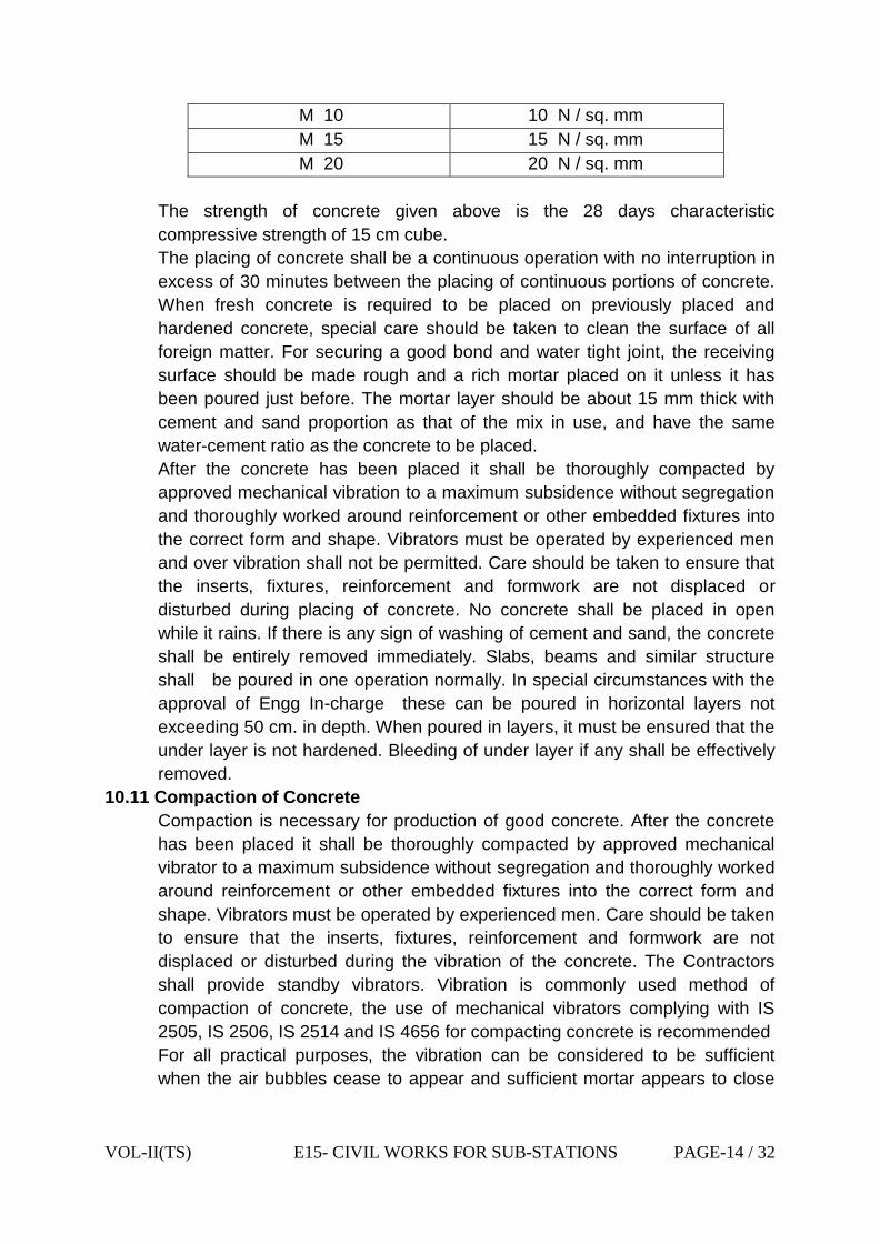
VOL-II(TS) E15- CIVIL WORKS FOR SUB-STATIONS PAGE-14 / 32
M 10 10 N / sq. mm
M 15 15 N / sq. mm
M 20 20 N / sq. mm
The strength of concrete given above is the 28 days characteristic
compressive strength of 15 cm cube.
The placing of concrete shall be a continuous operation with no interruption in
excess of 30 minutes between the placing of continuous portions of concrete.
When fresh concrete is required to be placed on previously placed and
hardened concrete, special care should be taken to clean the surface of all
foreign matter. For securing a good bond and water tight joint, the receiving
surface should be made rough and a rich mortar placed on it unless it has
been poured just before. The mortar layer should be about 15 mm thick with
cement and sand proportion as that of the mix in use, and have the same
water-cement ratio as the concrete to be placed.
After the concrete has been placed it shall be thoroughly compacted by
approved mechanical vibration to a maximum subsidence without segregation
and thoroughly worked around reinforcement or other embedded fixtures into
the correct form and shape. Vibrators must be operated by experienced men
and over vibration shall not be permitted. Care should be taken to ensure that
the inserts, fixtures, reinforcement and formwork are not displaced or
disturbed during placing of concrete. No concrete shall be placed in open
while it rains. If there is any sign of washing of cement and sand, the concrete
shall be entirely removed immediately. Slabs, beams and similar structure
shall be poured in one operation normally. In special circumstances with the
approval of Engg In-charge these can be poured in horizontal layers not
exceeding 50 cm. in depth. When poured in layers, it must be ensured that the
under layer is not hardened. Bleeding of under layer if any shall be effectively
removed.
10.11 Compaction of Concrete
Compaction is necessary for production of good concrete. After the concrete
has been placed it shall be thoroughly compacted by approved mechanical
vibrator to a maximum subsidence without segregation and thoroughly worked
around reinforcement or other embedded fixtures into the correct form and
shape. Vibrators must be operated by experienced men. Care should be taken
to ensure that the inserts, fixtures, reinforcement and formwork are not
displaced or disturbed during the vibration of the concrete. The Contractors
shall provide standby vibrators. Vibration is commonly used method of
compaction of concrete, the use of mechanical vibrators complying with IS
2505, IS 2506, IS 2514 and IS 4656 for compacting concrete is recommended
For all practical purposes, the vibration can be considered to be sufficient
when the air bubbles cease to appear and sufficient mortar appears to close

VOL-II(TS) E15- CIVIL WORKS FOR SUB-STATIONS PAGE-15 / 32
the surface and facilitate easy finishing operations. The period of vibration
required for a mix depends upon the workability of the mix.
10.12 Curing of Concrete
In order to achieve proper and complete strength of the concrete, the loss of
water from evaporation should be prevented. Eighty to eighty five per cent of
the strength is attained in the first 28 days and hence this 28-day strength is
considered to be the criterion for the design and is called characteristic
strength. The concrete after setting for 24 hours shall be cured by keeping the
concrete wet continuously for a period of 10 days after laying.
The curing increases compressive strength, improves durability,
impermeability and abrasion resistance. Failure to carry out satisfactory curing
can lead to cracking in the concrete. This in turn can lead to salt attack of the
reinforcement and consequential failure of the structure. If cracks occur in a
structure which are severe enough to affect the structure, the Contractor shall
cut out and replace the defective concrete at his own cost. The Contractor‟s
attention is, therefore, drawn to this particular aspect of proper and adequate
curing
10.13 Removal of formwork
Formwork shall be kept in position fully supported, until the concrete has
hardened and gained sufficient strength to carry itself and any loads likely to be
imposed upon it. Stripping must be effected in such a manner and at such a time
that no shock or other injury is caused to the concrete. The responsibility for
safe removal rests with the Contractor but the Engg In-charge may delay the
time of striking if he deems it necessary.
Minimum periods, in the absence of agreement to the contrary, between
completion of concreting and removal of forms are given below but due regard
must be paid to the method of curing and prevailing conditions during this period.
Removal of forms are to be done as under
i) Sides of foundations, columns, beams and wall 2days
ii) Under side of slabs up to 4.5 m span 7days
iii) Under side of slabs above to 4.5 m span
and underside of beams and arches up to 6m span 14days
iv) Under side of beams and arches above 6m and up to 9m span 21days
11. CONTROL ROOM CUM SWITCHGEAR BUILDING
11.1 General
The scope includes the construction of control room building alongwith office
rooms & toilets. The size of the building will be 17m X 10m.The tentative
layout showing the facilities to be provided is indicated at E21. However, the
size and layout of the building may be modified if the site condition does allow
for it. The modification to be done with prior approval of the Engineer in
Charge.
VOL-II(TS) E15- CIVIL WORKS FOR SUB-STATIONS PAGE-16 / 32
11.2 Specifications
Normally the building shall have the following design/construction parameters.
i. The structure will be of framed structure with M-20 grade concrete.
ii. The size and of specification of structural members like footings, columns,
beams, lintel, slab, staircase etc. and will be as per approved structural
drawings. However size of footings may be changed from site to site as per
safe bearing capacity of soil at corresponding sites
iii. Flooring – Artificial stone flooring will be provided in control room and
Vitrified tile flooring in other rooms except toilets will be provided.
iv. Bath room – Ceramic tiles in walls as well as in floors.
v. Inside wall – Primer and plastic emulsion paint.
vi. Outside wall – Primer with weather seal coat.
vii. Door – 2100x2550mm size Collapsible Iron doors, 2 nos. will be provided
in control room. 1070x2100mm size wooden doors in office rooms and
store rooms will be provided.
viii. Toilet doors will be of fibre reinforced plastic (FRP) type.
ix. All windows and ventilators will be of aluminium glazed type.
x. A service verandah has been provided in front side of building with a
staircase to provide access to terrace.
xi. A security room of 2000x2000mm size and a service portico 4000X3000
mm size adjacent to it has been provided,
The building design shall also take into consideration the layout of the panels,
switchboards, switchgear and other equipment in order to allow enough area
for the future extension of switchyard depending upon the availability of Sub-
Engineer in Charge area.
The building auxiliary services such as air conditioning and ventilation
systems, fire protection and detection systems and all other miscellaneous
services shall be designed in accordance with the requirements specified in
relevant sections of this Specifications to allow for easy access to equipment
and maintenance of the equipment
The doors and windows of the building shall be of aluminium extruded
channels, angles etc. The windows shall be provided with sliding shuttering
facilities and also to be provided with aluminium make grills.
11.3 Dimensions
An open space of one metre minimum shall be provided on the periphery of
the rows of panels, and equipment generally, in order to allow easy operator
movement and access as well as maintenance.
The building design shall also take into consideration the layout of the panels,
switchboards, switchgear and other equipment in order to allow enough area
for the future extension of switchyard depending upon the availability of
substation area.

VOL-II(TS) E15- CIVIL WORKS FOR SUB-STATIONS PAGE-17 / 32
The building auxiliary services such as air conditioning and ventilation
systems, fire protection and detection systems and all other miscellaneous
services shall be designed in accordance with the requirements specified in
relevant sections of this Specifications to allow for easy access to equipment
and maintenance of the equipment
The doors and windows of the building shall be of aluminium extruded
channels, angles etc. The windows shall be provided with sliding shuttering
facilities and also to be provided with aluminium make grills.
In Urban area of traditional 33/11 Kv S/S the Control Room area is 15x8 Mts.
In rural area of traditional 33/11 Kv S/S the Control Room area is 10x8 Mts.
11.4 Submission of data for approval
The following information shall be submitted for review and approval to the
Engg In-charge :
Design criteria for structural steel and reinforced concrete design. The
criteria shall comprise the codes and standards used, applicable climatic
data including wind loads, earthquake factors and maximum and
minimum temperatures applicable to the building locations, assumptions
of dead and live loads, including equipment loads, impact factors, safety
factors and other relevant information.
Structural design calculations and drawings including those for
construction and fabrication for all reinforced concrete and structural steel
structures.
Fully dimensioned floor plans, cross sections, longitudinal sections and
elevations of each building. These drawings shall be drawn at a scale
not less than 1:50 and shall identify the major building components.
Fully dimensioned drawings showing details and sections, drawn to scales
of sufficient size to clearly show sizes and configuration of the building
components and the relationship between them.
Product information of building components and materials, including walls,
partitions, flooring, ceilings, roofing, doors and windows and building
finishes.
A detailed schedule of building finishes including colour schemes.
A door and window schedule showing door types and locations, door lock
sets and latch sets and other door hardware.
Anti Termite treatment of Control Room to be done by the contractor.
Approval of the above information shall be obtained before ordering materials
or starting fabrication or construction as applicable.
11.5 Flooring (52 mm Thick)
Flooring shall be done as per provision made in the price schedule (BOQ).
11.6 Walls

VOL-II(TS) E15- CIVIL WORKS FOR SUB-STATIONS PAGE-18 / 32
Walls shall be constructed with K.B. Bricks with C.M. (1:6) as per provision
made in the drawing and price schedule (BOQ).
11.7 Plastering
All internal walls shall have minimum 16mm thick 1:6 cement sand plaster.
The ceiling shall have 6mm thick 1:4 cement sand plaster.
11.8 External Finish
All external surfaces shall have painted with weather proof synthetic paints
over 12mm thick cement sand plaster in two layers. Under layer 12mm thick
cement plaster 1:6 (1 cement:6 coarse sand) and a top layer 6mm thick
cement plaster 1:3 (1 cement:3 coarse sand) finished rough with sponge.
All ceilings shall be white based plastic emulsion paints and the internal walls
are also to be provided with plastic emulsion synthetic paints. The outer of the
building shall be provided with weather seal coats of synthetic paints.
11.9 Roof
Roof of the building shall consist of cast in situ R.C.C. slabs (M-20) grade.
Extra heavy water proofing treatment of approved standard shall be done.
11.10 Plumbing And Sanitation
All plumbing and sanitation work shall be executed to comply with the
requirements of the appropriate bye laws, rules and regulations of the Local
Authority having jurisdiction over such matters. The Contractor shall arrange
for all necessary formalities to be met in regard to inspection, testing, obtaining
approval and giving notices etc.
An overhead water tank of adequate capacity depending on the number of
users for 24 hours storage shall be provided.
Galvanised MS pipe of medium class conforming to IS : 1239 shall be used for
internal piping works for portable water supply.
Sand C I pipes with lead joints conforming to IS:1729 shall be used for
sanitary works above ground level.
A list of toilet fittings will be approved by the Engg In-charge , before
procurement by the contractor and same will be inspected by the Engg In-
charge before installation. Sufficient nos of toilets and bath rooms including
separate urinal provision shall be provided at both ground and first floors.
Required nos of wash basins (stand type) with good quality mirrors and other
accessories as required are also to be provided at both ground and first floor
of control room building. Same procedure for colony quarters also.
12.0 EARTHING : Earth Grid should not be more than TWO meters square. This should be done
by using 75x10 mm GI flats. Earth risers should be 50x6 mm GI flats. All
equipments & metal parts of the Sub-Station should be connected with main
earth grid by using 50x6 GI flats at two different places. The main earth grid
should be laid not less than 600 mm below the finished ground level. The lap

VOL-II(TS) E15- CIVIL WORKS FOR SUB-STATIONS PAGE-19 / 32
welding should not less than 100 mm. The welding of joints should be done
after removal of Zinc by using Blow lamps. Welding should be done in all four
sides and should be double layer continuous. Before taking up the second
layer welding the deposited flux should be removed. During welding the two
flats should be tightened properly by using „C„ clamps. Immediately after
welding two layers of anti-corrosive paints should be painted over the welded
portion along with two coats of Black bituminous paints. Before back filling of
earth trenches the welded portion should be covered by wrapping with
bituminous tape properly and also jointing portion should be covered with PCC
(1:3:6) mix. The backfilling of earth pits and trenches should be done with
powered loam soil mixed with Bentonate powder (10:1) mix.
All equipments, steel structures etc should be connected with Main earth mat
at two rows separately. All LAs, PTs , Columns having spikes should
individually connected with individual Pipe electrodes and again should be
connected with main earth grid at two separate places. The Neutral of Power
Transformer should be connected with two separate pipe electrodes and again
connected with main earth electrodes at two separate places. The separation
distance between each pipe electrodes should not be less than 2 mts. The
back filling of pipe electrodes should be done in layer of Charcoal, Salt & loam
soil mixed with Bentonate power.
There should be a closely spaced earth grid ( 1.5 mts square having .5 mts
spacing) below the mechanism boxes of each Isolators & AB switches. In Sub-
station the diameter of pipe electrode should not be less than 50 mm. The
Flange( 50x6) mm GI flat should be welded in all sides with Pipe electrode. In
each face of Flange there should be two nos 17.5 mm hole to accommodate
16 mm GI Bolt nut with 1 no spring washer.
There should be one 50x6 mm earth flat run over the cable rack and should be
connected with main earth grid at an interval of 5 mts The jointing portion of
earth flats over the ground should be painted with two coats of Anti-corrosive
paints and two coats of good quality of Aluminium paints (Berger/Asian
paints).
12.01 (A) G.I. Flat (75x 10 mm) & G.I.Flat (50 x 6 mm)
The specification covers manufacture, testing and supply of Galvanized Steel
flat for Earthing arrangements.
I. APPLICABLE STANDARDS:
Materials shall conform to the latest applicable Indian standards. In case
bidders offer steel section and supports conforming to any other international
specifications which shall be equivalent or better than IS, the same is also
acceptable.
VOL-II(TS) E15- CIVIL WORKS FOR SUB-STATIONS PAGE-20 / 32
Sl. No. Standard No. Title
1 IS:2062 Grade „A‟ Quality Specification for M.S. Channel and M.S. Flat
2 IS:2062 Chemical and Physical Composition of material
3 IS:1852 Rolling and Cutting Tolerances for Hot Rolled
Steel products
II. RAW MATERIAL :
The steel section shall be re-rolled from the BILLETS/INGOTS of tested
quality from SAIL/TATA/RINL as per latest version of IS: 2830. The chemical
composition and physical properties of the finished materials shall be as per
the relevant standards.
III. TEST
Steel sections shall be tested in IS approved laboratory or standard laboratory
of the Bidder country having all facilities available for conducting all the tests
as prescribed in relevant IS or IEC or to any equivalent International laboratory
or Institutions.
IV. PHYSICAL & CHEMICAL PROPERTIES
Length
The GS Flat to be supplied shall be in 5.5 meters to 13 meters lengths.
Weighment
The weighment of GS Flat shall be witnessed by the consignee at the time of
taking delivery. The weight recorded in the material receipt certificate issued
by the consignees shall be final.
Chemical composition and physical properties of M.S.Channels and M.S.Flat
conforming to IS: 2062/84L composition.
Chemical Composition For Fe 410 WA Grade
1 C - 0.23% MAX.
2 Mn - 1.5% MAX.
3 S - 0.050% MAX.
4 P - 0.050% MAX.
5 SI - 0.40% MAX.
6 CE - 0.42% MAX.

VOL-II(TS) E15- CIVIL WORKS FOR SUB-STATIONS PAGE-21 / 32
(Carbon Equivalent)
V. Mechanical Properties
1. Tensile strength Kgf/mm²ˉ - 410
2. Yield stress Min. for thickness/diameter <20 m - 26 Kgf/mm²
20-40 mm - 24Kgf/mm²
40 mm - 23Kgf/mm
3. Elongation % - 23%
4. Bend Test (Internal Dia) Min-3t (this the thickness of the material)
VI. MARKING
It is desirable that the Bidders should put his identification marks on the
finished materials. The mark shall be in “legible English letters”
VII. METHOD OF GALVANISING:
Sl. No. Tests For GI Flat
1 Dip test 6 dips of 1 min each
2 Mass of Zinc coating 610 gram/sq.m minimum
Pre dispatch inspection shall be performed to witness following tests:
Freedom from defects,
Verification of dimensions
Galvanization tests
Mechanical tests
Chemical composition tests
These tests are to be performed and certified at Govt. recognized laboratory.
MS flat shall conform to IS 2062 & its latest amendments for steel &
Galvanization as per IS 4759 & its Latest amendments.
The flat shall be coated with Zn 98 Zinc grade.
The minimum Zinc coating shall be 610 gm/sqm for thickness more than 5 mm
and 460 gm/sqm for item thickness less than 5 mm.
For use in construction at coastal areas as well as other areas it shall be
required for galvanizing the Cross arms and Pole top brackets as following :
All galvanizing shall be carried out by the hot dip process, in accordance with
Specification IS 2629. However, high tensile steel nuts, bolts and spring
washer shall be electro galvanized to Service Condition 4. The zinc coating
shall be smooth, continuous and uniform. It shall be free from acid spot and
shall not scale, blister or be removable by handling or packing. There shall be

VOL-II(TS) E15- CIVIL WORKS FOR SUB-STATIONS PAGE-22 / 32
no impurities in the zinc or additives to the galvanic bath which could have a
detrimental effect on the durability of the zinc coating.
Before picking, all welding, drilling, cutting, grinding and other finishing
operations must be completed and all grease, paints, varnish, oil, welding slag
and other foreign matter completely removed. All protuberances which would
affect the life of galvanizing shall also be removed.
The weight of zinc deposited shall be in accordance with that stated in
Standard IS 2629 and shall not less than 0.61kg/m² with a minimum
thickness of 86 microns for items of thickness more than 5mm,
0.46kg/m² (64 microns) for items of thickness between 2mm and 5mm
and 0.33kg/m² (47 microns) for items less than 2mm thick.
Parts shall not be galvanized if their shapes are such that the pickling
solutions cannot be removed with certainty or if galvanizing would be
unsatisfactory or if their mechanical strength would be reduced. Surfaces in
contact with oil shall not be galvanized unless they are subsequently coated
with an oil resistant varnish or paint.
In the event of damage to the galvanizing the method used for repair shall be
subject to the approval of the Engineer in Charge or that of his representative.
Repair of galvanizing on site will generally not be permitted.
The threads of all galvanized bolts and screwed rods shall be cleared of
spelter by spinning or brushing. A die shall not be used for cleaning the
threads unless specifically approved by the Project Manager. All nuts shall be
galvanized. The threads of nuts shall be cleaned with a tap and the threads
oiled.
Partial immersion of the work shall not be permitted and the galvanizing tank
must therefore be sufficiently large to permit galvanizing to be carried out by
one immersion.
After galvanizing no drilling or welding shall be performed on the galvanized
parts of the equipment excepting that nuts may be threaded after galvanizing.
To avoid the formation of white rust galvanized materials shall be stacked
during transport and stored in such a manner as to permit adequate
ventilation. Sodium dichromate treatment shall be provided to avoid formation
of white rust after hot dip galvanization.
The galvanized steel shall be subjected to test as per IS-2633.
VOL-II(TS) E15- CIVIL WORKS FOR SUB-STATIONS PAGE-23 / 32
The galvanization tests are to be conducted as per IS: 2633/72 & IS: 6745/72
& its latest amendments.
12.1. (B) Earth Electrode (50 NB 3.0 Mtr Length)
Metal parts of all equipment other than those forming part of an electrical
circuit shall be connected directly to the main earth system via two separate
conductors of adequate capacity at two different points.
All main members of structural steelworks shall be earthed by galvanised iron
flat connections bonded by welding or bolting to the steelworks.
Connections to apparatus and structures shall be made clear of ground level,
preferably to a vertical face and protected as appropriate against electrolytic
corrosion. They shall be made between clean surfaces and of sufficient size
and pressure to carry the rated short circuit current without damage.
Earth bars installed directly into the ground should normally be laid bare and
the trench back-filled with a fine top soil. Where the soil is of a hostile nature,
special precautions must be taken to protect the earth bar. Wherever required
to achieve the required resistance bentonite powder to be mixed in lom/ black
cotton crushed soil in 1: 6 proportion is permissible, the method used being
subject to the agreement of the Engg. Incharge . In the event of bentonite
powder being adopted, water supply through conduit to the area must be
supplemented and regulated to keep the surface / mat moisture absorbent.
Joints in earth bars+ shall be welded and then coated with a suitable anti-
corrosion protection treatment.
Facilities shall be provided on the earth bar run between equipment and the
base of structures, comprising a looped strip, so as to permit the attachment of
portable earth connections for maintenance purposes.
The cross sectional area of the earth bar and connections shall be such that
the current density is not greater than 100 A/mm2 for a 3 second fault duration.
13.0 WIRING, CABLING AND CABLE INSTALLATION
13.1 Cubicle wiring
Panels shall be complete with interconnecting wiring between all electrical
devices in the panels. External connections shall be achieved through terminal
blocks. Where panels are required to be located adjacent to each other all
inter panel wiring and connections between the panels shall be carried out
internally. The Contractor shall furnish a detailed drawing of such inter panel
wiring. The Contractor shall ensure the completeness and correctness of the
internal wiring and the proper functioning of the connected equipment.

VOL-II(TS) E15- CIVIL WORKS FOR SUB-STATIONS PAGE-24 / 32
All wiring shall be carried out with 1.1 kV grade, PVC insulated, single core,
stranded copper wires. The PVC shall have oxygen index not less than ‘29’
and Temperature index not less than 250C. The wires shall have annealed
copper conductors of adequate size comprise not less than three strands.
The minimum cross sectional area of the stranded copper conductor used for
internal wiring shall be as follows :
a) All circuits excepting CT circuits and energy metering circuit of VT 2.5
sq.mm
b) All CT circuits and metering circuit of VT 2.5 sq. mm
All internal wiring shall be supported, neatly arranged, readily accessible and
connected to equipment terminals and terminal blocks. Wiring gutters and
troughs shall be used for this purpose.
Cubicle connections shall be insulated with PVC to IEC 227. Wires shall not
be jointed or teed between terminal points.
Bus wires shall be fully insulated and run separately from one another.
Auxiliary bus wiring for AC and DC supplies, voltage transformer circuits,
annunciation circuits and other common services shall be provided near the
top of the panels running throughout the entire length of the panel suite.
Longitudinal troughs extending throughout the full length of panel shall be
preferred for inter panel wiring.
All inter connecting wires between adjacent panels shall be brought to a
separate set of terminal blocks located near the slots of holes meant for the
passage of the interconnecting wires. Interconnection of adjacent panels on
site shall be straightforward and simple. The bus wires for this purposes shall
be bunched properly inside each panel.
Wire termination shall be made with solderless crimping type and tinned
copper lugs which firmly grip the conductor. Insulated sleeves shall be
provided at all the wire terminations. Engraved core identification plastic
ferrules marked to correspond with panel wiring diagram shall be fitted at both
ends of each wire. Ferrules shall fit tightly on the wire and shall not fall off
when the wire is disconnected from terminal blocks. Numbers 6 and 9 shall not
be included for ferrules purposes unless the ferrules have numbers
underscored to enable differentiation. (i.e. 6 and 9 ).
Fuses and links shall be provided to enable all circuits in a cubicle, except a
lighting circuit, to be isolated from the bus wires.
The DC trip and AC voltage supplies and wiring to main protective gear shall
be segregated from those for back-up protection and also from protective
apparatus for special purposes. Each such group shall be fed through
separate fuses from the bus wires. There shall not be more than one set of
VOL-II(TS) E15- CIVIL WORKS FOR SUB-STATIONS PAGE-25 / 32
supplies to the apparatus comprising each group. All wires associated with the
tripping circuits shall be provided with red ferrules marked “Trip”.
It shall be possible to work on small wiring for maintenance or test purposes
without making a switchboard dead.
The insulation material shall be suitably coloured in order to distinguish
between the relevant phases of the circuit.
When connections rated at 380 volt and above are taken through junction
boxes they shall be adequately screened and “DANGER” notices shall be
affixed to the outsides of junction boxes or marshalling kiosk.
Where connections to other equipment and supervisory equipment are
required the connections shall be grouped together.
13.2 LV power cabling
LVAC cable terminals shall be provided with adequately sized, hot pressed,
cast or crimp type lugs. Where sweating sockets are provided they shall be
without additional clamping or pinch bolts. Where crimp type lugs are provided
they shall be applied with the correct tool and the crimping tool shall be
checked regularly for correct calibration. Bi-metallic joints between the
terminals and lugs shall be provided where necessary.
Terminals shall be marked with the phase colour in a clear and permanent
manner.
A removable gland plate shall be provided by the Contractor. The Contractor
shall be responsible for drilling the cable gland plate.
Armoured cables shall be provided with suitable glands for terminating the
cable armour and shall be provided with an earthing ring and lug to facilitate
connection of the gland to the earth bar.
13.2 Multi-core cables and conduit wiring
External multi-core cabling between items of main and ancillary equipment
shall form part of the Contract Works and shall consist of un-armoured multi-
core cable with stranded copper conductors PVC insulated and PVC over
sheathed complying with the requirements of IEC 227 and 228 as applicable.
Multi-core cable for instrumentation and control purposes shall be supplied
with 2.5 mm2 stranded copper cores. Multi-core cables for CT and VT circuits
shall be supplied with two by 2.5 mm2 stranded copper cores and the cores
shall be identified by the phase colour.
Where conduit is used the runs shall be laid with suitable falls and the lowest
parts of the run shall be external to the equipment. All conduit runs shall be

VOL-II(TS) E15- CIVIL WORKS FOR SUB-STATIONS PAGE-26 / 32
adequately drained and ventilated. Conduits shall not be run at or below
ground level.
Multi-core cable tails shall be so bound that each wire may be traced to its
cable without difficulty. All multi-core cables shall be provided with 20 % spare
cores and the spare cores shall be numbered and terminated at a terminal
block in the cubicle. Where cables are terminated in a junction box and the
connections to a relay or control cubicle are continued in conduit, the spare
cores shall be taken through the conduit and terminated in the cubicle. The dc
trip and ac voltage circuits shall be segregated from each other as shall the
circuits to main protective gear be segregated from those for back-up
protection.
The screens of screened pairs of multi-core cables shall be earthed at one end
of the cable only. The position of the earthing connections shall be shown
clearly on the diagram.
All wires on panels and all multi-core cable cores shall be crimped with the
correct size of crimp and crimping tool and will have ferrules which bear the
same number at both ends. At those points of interconnection between the
wiring carried out by separate contractors where a change of number cannot
be avoided double ferrules shall be provided on each wire. The change of
numbering shall be shown on the appropriate diagram of the equipment. The
same ferrule number shall not be used on wires in different circuits on the
same panels.
The Contractor shall provide a two (2) metre loop of spare cable at both ends
of all multi-core cable runs and shall leave sufficient lengths of tails at each
end of the multi-core cables to connect up to the terminal boards. The
Contractor shall also strip, insulate, ring through and tag the tails and shall
also seal the cable boxes. The Contractor shall be responsible for re-checking
the individual cores and for the final connecting up and fitting of numbered
ferrules within all equipment provided on this contract.
The drilling of gland plates, supply and fitting of compression glands and
connecting up of power cables included in the Contract scope of work shall be
carried out under this contract.
14.0 Laying and installing of cables
14.1 General
For cable laying the following shall apply:
a) Switchyard area In concrete cable troughs (cable trench having
cable racks with ladder type cable trays)
b) Control Room On cable racks consisting of slotted type and
ladder type cable trays
c) Buildings Conduits
VOL-II(TS) E15- CIVIL WORKS FOR SUB-STATIONS PAGE-27 / 32
Directly buried cables shall be used wherever necessary with the approval of
Engg. Incharge .
14.2 Laying of cable
Cables shall be laid in concrete troughs provided under this contract or drawn
into pipes or ducts or on cable racks or directly buried as may be required by
the Engg. Incharge . All cable supports shall be earthed in accordance with
IS 3043.
The cable support system shall be designed and constructed to carry the
required cables without undue crowding of the supports and without
overloading the supports. The maximum number of layers of cable that shall
be permitted on a single cable support shall be three. The width of the cable
supports shall be selected to ensure that the supports are not crowded, the
cable supports are not overloaded and that sufficient space is provided in the
cable trough to allow for personnel access during and after cable installation.
Where cables pass under roadways they shall be laid in pipes at a depth not
less than 800 mm below the surface.
The Contractor shall be responsible for the excavation of trenches which shall
include all pumping and baling required and the provision of all necessary
labour, plant, tools, water, additional soil, fuel or motor power for such
purposes.
Cables in trenches will be inspected by the Engg. Incharge before the
trenches are backfilled.
The running of communications and power cables along the same route shall
be avoided as far as possible. Where this is not possible they shall be
segregated, the one group from the other. Power and communication cables
shall be laid in separate tiers. For other than directly buried cables the order of
laying of various cables shall be as follows:
a) Power cables on top tiers.
b) Control/ instrumentation and other service cables in bottom tiers.
14.3 Cable tags and markers
Each cable and conduit run shall be tagged with numbers that appear in the
cable and conduit schedule.
The tag shall be of aluminum with the number punched on it and securely
attached to the cable conduit by not less than two turns of 20 SWG GI wire
conforming to IS 280. Cable tags shall be of rectangular shape for power
cables and of circular shape for control cables.
VOL-II(TS) E15- CIVIL WORKS FOR SUB-STATIONS PAGE-28 / 32
Location of cables laid directly in the ground shall be clearly indicated with
cable marker made of galvanised iron plate.
Location of buried cable joints shall be indicated with a cable marker having an
additional inscription "Cable joint".
Cable markers shall project 150 mm above ground and shall be spaced at an
interval of 30 meters and at every change in direction. They shall be located
on both sides of road and drain crossings.
Cable tags shall be provided on all cables at each end (just before entering
the equipment enclosure), on both sides of a wall or floor crossing, on each
duct, conduit entry and at every twenty meters (20 m) in cable tray/trench
runs. Cable tags shall be provided inside switchgear, motor control centres,
control and relay panels etc. and wherever required for cable identification
when a number of cables enter together through a gland plate.
The price of cable tags and markers shall be included in the installation rates
for cables/conduits quoted by the Bidder.
14.4 Cable supports and cable tray mounting arrangements in control room
The control room will normally be provided with embedded steel inserts on
concrete floors/walls for the purpose of cabling in the control room. The
supports shall be secured by welding to these inserts or available building
steel structures. However, in cases where no such embedded steel inserts are
available, the same shall have to secure to the supports on walls or floors by
suitable anchoring.
14.5 Cable support structure in switchyard cable trenches
The contractor shall fabricate and install cable support structures in cable
trenches. These supports shall be provided at 750 mm spacing along the run
of cable trenches.
Cable supports and cable racks shall be fabricated from standard structural
steel members, channels, angles and flats of required size. The fabrication.
welding and erection of these structures shall conform to the relevant clauses
of this Specification, in addition to the specification given herein.
14.6 Termination of cables and wires
Where cables leave the apparatus in an upward direction the cable boxes
shall be provided with a barrier joint to prevent leakage of cable oil or
compound into the apparatus. Where cable cores are liable to contact with oil
or oil vapour the insulation shall be unaffected by oil.

VOL-II(TS) E15- CIVIL WORKS FOR SUB-STATIONS PAGE-29 / 32
PVC sheathed cables shall be terminated by compression glands complying
with BS 6121 (or equivalent).
Auxiliary PVC insulated cables shall be terminated with compression type
glands, clamps or armour clamps complete with all the necessary fittings.
Colours shall be marked on the cable box, cable tail ends and single core
cables at all connecting points and/or any positions the Engg. Incharge may
determine. Cable boxes shall be provided with suitable labels indicating the
purpose of the supply where such supply is not obvious or where the Engg.
Incharge may determine.
All cables shall be identified and shall have phase colours marked at their
termination.
All incoming and outgoing connections shall be terminated at a terminal block.
Direct termination into auxiliary switches will not be accepted.
15.0 SUPPLY VOLTAGE
The auxiliary supply voltages on site shall be as follows:
Nominal
Voltage V
Variation Frequency Hz
or DC
Phas
e
Wires Neutral
Connection
430 ±10% 50 (-5% , +3%) 3 4 Solidly earthed
230 ±10% 50(-5% , +3%) 1 2 Solidly earthed
24 DC DC 2
16.0 ERECTION CONDITIONS
16.1 General
The following shall supplement the conditions already contained in the other
parts of these specifications and documents and shall govern that portion of
the work on this Contract to be performed at Site.
17.0 Contractor's field operation
17.1General
The Contractor shall inform the Engg. Incharge in advance of field activity
plans and schedules for carrying-out each part of the works. Any review of
such plans or schedules or methods of work by the Engg. Incharge shall not
relieve the Contractor of any of his responsibilities towards the field activities.
Such reviews shall not be considered as an assumption of any risk or liability
by the Employer or any of his representatives, and no claim of the Contractor
will be entertained because of the failure or inefficiency of any such plan or
schedule or method of work reviewed. The Contractor shall be solely
responsible for the safety, adequacy and efficiency of plant and equipment
and his erection methods.

VOL-II(TS) E15- CIVIL WORKS FOR SUB-STATIONS PAGE-30 / 32
17.2 Facilities to be provided by the contractor
17.3 Unloading
Contractor shall make his own arrangement for unloading the equipment at
site.
17.4 Tools, tackle and scaffoldings
The Contractor shall provide all the construction equipment tools, tackle and
scaffoldings required for offloading, storage, pre-assembly, erection, testing
and commissioning of the equipment covered under the Contract. He shall
submit a list of all such materials to the Engg. Incharge before the
commencement of pre-assembly at Site. These tools and tackles shall not be
removed from the Site without the written permission of the Engg. Incharge .
The Contractor shall maintain an accurate and exhaustive record detailing all
equipment received by him for the purpose of erection and keep such record
open for the inspection of the Engg. Incharge .
All equipment shall be handled carefully to prevent any damage or loss. All
equipment stored shall be properly protected to prevent damage. Equipment
from the store shall be moved to the actual location at an appropriate time so
as to avoid damage of such equipment at Site.
All the materials stored in the open or dusty location shall be covered with
suitable weather-proof and flameproof covering material.
The Contractor shall be responsible for making suitable indoor facilities for the
storage of all equipment which requires to be kept indoors.
18.0 SITE CLEARANCE
18.1 Clearing and uprooting of tree
The work shall also consist of numbering of trees, removing and disposing of
all materials such as trees, bushes, woods, shrubs, grass, stumps, rubbish,
rank vegetation, roots, foreign materials, etc., which in the opinion of the Engg
In-charge are unsuitable for incorporation in the works, from within the limits
and such other areas as may be specified on the drawings or directed by the
Engg In-charge . Clearing and uprooting of tree shall be performed in advance
of earthwork operations and in accordance with the requirements of these
Specifications and taking prior permission from forest department. During
clearing and grubbing, the contractor shall take all adequate precautions
against soil erosion, water pollution etc., and where required undertake
additional works to that effect.
Provision of plantation and developing a garden inside the sub-station.
At least, 100 nos. flowers bearing plants as per the advice of Engineer-in-
charge to be planted along the road side and in and around the control room
building after making surface treatment. Provision of water taps facilities at

VOL-II(TS) E15- CIVIL WORKS FOR SUB-STATIONS PAGE-31 / 32
different locations for watering the plants and as well as to the peripheral earth
pits.
18.2 Programme
The Contractor shall construct the works in compliance with the outline
programme appended to the Bidding Document, and shall submit for the
approval of the Engg In-charge a detailed programme in accordance with the
requirements of this Specification.
18.3 Inclement weather
As per relevant Code, during hot weather, precautions shall be taken to avoid
premature stiffening of the fresh concrete mix and to reduce water absorption
and evaporation losses. During hot weather (atmospheric temperature above
40 degree C) or cold weather (atmospheric temperature at or below 5deg.C)
concreting shall be done as per the procedure set out in IS 7861.
18.4 STANDARDS
All Civil works shall be carried out as per applicable Indian Laws, latest
revision of International Standards and Codes. All materials shall be of best
quality confirming to relevant Indian Standards and Codes.
Civil works shall be designed to the required service conditions and /or loads
as specified elsewhere in this Specification or implied as per National and
International Standards.
19.0 MATERIALS AND WORKMANSHIP
19.1 General
All materials used in the works shall be new and of the best quality of their
respective kinds. They shall comply with the requirements of the latest edition
of any relevant Indian Standard or Code of Practice where such exist, and
current at the date of tendering.
All workmanship shall be of the highest standard, and shall be executed by
competent men skilled in their respective trades.
19.2 Samples
In addition to the special provisions made in this specification for sampling and
testing of materials by particular methods, samples of any materials and
workmanship proposed to be used in the Works may be called for at any time
during the Contract by the Engg In-charge and shall be furnished by the
Contractor without delay and at the expense of the Contractor. Samples when
approved, shall be regarded as the acceptable standard, and any material or
workmanship subsequently not complying with that standard shall be rejected
and replaced by those of acceptable standard at the expense of the
Contractor. Sample storage boxes shall be provided by the Contractor free of
cost if requested by the Engg In-charge .

VOL-II(TS) E15- CIVIL WORKS FOR SUB-STATIONS PAGE-32 / 32
19.3 Tests
Whenever considered desirable by the Engg In-charge , Inspectors may be
sent to manufacturer‟s or subcontractors‟ premises to test materials or
supervise their manufacture.
Where specified or requested the Contractor shall obtain from the
manufacturer and send to the Engg In-charge certificates of test, proof
sheets, mill sheets, etc., showing that materials have been tested in
accordance with this Specification or the relevant Indian Standard.
Notwithstanding any tests which may be directed to be carried out at a
manufacturer‟s and/or subcontractor‟s works, the Engg In-charge may carry
out any tests or further tests he considers necessary or desirable after delivery
of materials to the Site.
The Contractor shall provide all labour, equipment and facilities necessary for
carrying out the tests both in works and on site.
The cost of routine tests required by IS and this Specification shall be borne by
the Contractor. The cost of other tests shall be borne in accordance with the
Conditions of Contract.
19.4 Names of suppliers and copies of orders
If so required, and before ordering material of any description, the Contractor
shall submit for approval the names of makers or suppliers proposed. Copies
of orders shall also be submitted if so required. The Engg In-charge may at
any time withdraw his previously given approval to obtaining materials from
any maker or supplier should such maker or supplier fail to supply materials of
the specified quality or quantity in the requisite time.
19.5 Rejection of materials and workmanship
The Engg In-charge shall at any time have power to reject materials and
workmanship not complying with this Specification or with the approved
Drawings. Materials so rejected shall be immediately removed from site and
replaced by materials of an approved standard at the expense of the
Contractor. Rejected workmanship shall be broken out and replaced by work
of an acceptable standard including the supply of new materials by the
Contractor, at the expense of the Contractor, and without delay.
19.6 Cube Testing
150mmX 150mm x 150mm cube from each concrete batch shall be prepared
and cure as per relevant IS and then shall be subject to laboratory test to determine
it‟s strength in accordance to the Indian Standard.

VOL-II(TS) E16- FIRE FIGHT & FIRE DETECTION SYSTEM PAGE - 1/9
CHAPTER- E16
TECHNICAL SPECIFICATION
FOR FIRE FIGHTING & FIRE DETECTION SYSTEM
VOL-II(TS) E16- FIRE FIGHT & FIRE DETECTION SYSTEM PAGE - 2/9
TABLE OF CONTENTS
OF
FIRE FIGHTING & FIRE DETECTION SYSTEM
NO DESCRIPTION PAGE NO
1.0 Intent of specification 3
2.0 Scope of supply 3
3.0 Codes and standards 3
4.0 Portable and wheel/ trolley mounted fire exting 4
5.0 Design and construction 4
6.0 Tests and inspection 5
7.0 Painting 5
8.0 Design criteria 6
9.0 Deviations 6
10.0 Data sheet for optical smoke dectector 6
11.0 Data sheet for heat dectector 7
12.0 Data sheet for ionisation smoke dectector 8
13.0 data sheet for fire alarm sounder (hooter) 8

VOL-II(TS) E16- FIRE FIGHT & FIRE DETECTION SYSTEM PAGE - 3/9
TECHNICAL SPECIFICATION FOR FIRE FIGHTING & FIRE DETECTION SYSTEM
1.0 INTENT OF SPECIFICATION
This specification is intended to cover the design, manufacture, assembly,
testing at manufacturer's works, supply & delivery, properly packed for transport
FOR site of Portable wall and trolley mounted Fire extinguisher and fire buckets
for substation control room building complete with all materials and accessories
for efficient and trouble free operation.
The fire extinguisher shall be procured from a vendor who must have at least
three years experience in manufacturing of the sam. The materials shall have
been successfully type tested during last five years on the date of bid
opening. The Type Test reports shall be submitted along with the bid.
2.0 SCOPE OF SUPPLY
The following equipment shall be furnished with all accessories: -
a. Wall mounted fire extinguisher
b. Trolley mounted fire extinguisher
c. Sand buckets with stand.
d. All installation hardware.
e. All relevant drawings, data & instruction manuals.
f. Mandatory spares.
g. Fire & smoke detection system for the building.
h. Any fire suppression system required for GIS shall be in scope of bidder.
3.0 CODES AND STANDARDS
All equipment and material shall be designed, manufactured and tested in accordance
with the latest applicable Indian Standards except where modified and/or
supplemented by this specification.
Equipment and materials conforming to any other standard, which ensures equal or
greater quality, may be accepted. In such case copies of the English version of the
standard adopted shall be submitted along with the bid.
In particular, the following standards and specifications are applicable.
Indian Elecrtricity Rules
Indian electricity act
IS 2190 Selection, installation & maintenance of first aid, fire extinguisher.
Tariff Advisory Committee Manual

VOL-II(TS) E16- FIRE FIGHT & FIRE DETECTION SYSTEM PAGE - 4/9
IS 1646 Code for practice for fire safety of buildings
IS 940 Portable fire extinguisher, Water type - specification
IS 2878 Fire extinguisher CO2 type
IS 2171 Specification for fire extinguisher dry powder.
IS 10204 Specification for fire extinguisher Mechanical foam type.
4.0 PORTABLE AND WHEEL/ TROLLEY MOUNTED FIRE EXTINGUISHERS
4.1 This specification lays down the requirement regarding fire extinguishers of
following types :
Portable fire extinguishers.
a) Pressurised water type.
b) Dry chemical powder type
c) Carbon Dioxide type
Wheel/ Trolley mounted fire extinguishers.
a) Mechanical foam type
4.2 All the extinguishers offered by the Bidder shall be of reputed make and shall be
ISI marked.
5.0 Design and Construction
5.1 All the portable extinguishers shall be of freestanding type and shall be capable
of discharging freely and completely in upright position.
5.2 Each extinguisher shall have the instructions for operating the extinguishers on
its body itself.
5.3 All extinguishers shall be supplied with initial charge and accessories as
required.
5.4 Portable type extinguishers shall be provided with suitable clamps for mounting
on walls or columns.
5.5 All extinguishers shall be painted with durable enamel paint of fire red colour
conforming to relevant Indian Standards.
5.6 Pressurisation of water type fire extinguishers shall either be done by
compressed air or by using gas cartridge. The constant air pressure type
shall conform to IS:6234 and the gas pressure type shall conform to IS:940.
Both these extinguishers shall be ISI marked.
5.7 Dry chemical powder type portable extinguisher shall conform to IS: 2171.

VOL-II(TS) E16- FIRE FIGHT & FIRE DETECTION SYSTEM PAGE - 5/9
5.8 Carbon Dioxide type portable extinguisher shall conform to IS:2878.
5.9 Wheel/ trolley mounted fire extinguishers of 50 litre capacity Mechanical foam
type shall conform to IS:13386
6.0 Tests and Inspection
6.1 A performance demonstration test at site of five (5) percent or one (1) number
whichever is higher, of the extinguishers shall be carried out by the
Contractor. All consumable and replaceable items require for this test would
be supplied by the Contractor without any extra cost to Employer.
6.2 Performance testing of extinguisher shall be in line of applicable Indian
Standards. In case where no Indian Standard is applicable for a particular
type of extinguisher, the method of testing shall be mutually discussed and
agreed to before placement of order for the extinguishers.
7.0 Painting
Each fire extinguisher shall be painted with durable enamel paint of fire red
colour conforming to relevant Indian Standards.
Fire Alarm arrangement to be provided for the control cum switchgear
Building.
Following Detection facility should be made available
(1) Smoke Detection Facility
(2) Fire Detection Facility
As the building will be used for keeping the indoor switchgear (GIS/AIS),
Relay Panels with Sub-station Automation System,Battery & Battery Charger
& other important Equipment.Care must be taken for protection against any
hazards due to fire.The system should be designed as per the latest standard
adopted for protection against fire for electrical control cum switchgear
Building.
Protection such detectors shall be provided considering the location of such
equipment (as explained above) & also size of the building.

VOL-II(TS) E16- FIRE FIGHT & FIRE DETECTION SYSTEM PAGE - 6/9
Contractor to design the same in consultant with the latest fire protection
standard & also with the manufacturer of the fire equipment.
The type & size of fire Extinguisher should be decided on the basis of design
in line with the latest standard followed.
Bidder to quote on Lumpsum basis.
This specification shall be read and constructed in conjunction with the bid
documents and annexure to determine the scope of work..
8.0 DESIGN CRITERIA
8.1. General
The contractor shall supply the required type and quantities of fire extinguisher and
Sand buckets. The quantity shall be as per TAC recommendations.
8.2. Location
Fire extinguisher and sand buckets shall be installed in Control room, battery
room, switchgear room, ACDB & battery charger room, Cable cellar, Transformer
yard, Outdoor switchyard and Capacitor bank.
8.3. Distribution
The fire extinguishers in various locations shall be as per the guidelines of TAC-
India. The maximum distance between placement of fire extinguishers shall be as
per TAC rules.
8.4. Tests
All equipment shall be completely assembled wired, adjusted and routine tested at
the factory as per relevant standards.
9.0 DEVIATIONS
Deviations from this Specification shall be stated in writing with the tender by
reference to the Specification clause/GTP/Drawing and a description of the
alternative offer. In absence of such a statement, it will be assumed that the bidder
complies fully with this specification. No deviation will be acceptable post order.
10.0 DATA SHEET FOR OPTICAL SMOKE DECTECTOR
I Manufacturer OPTCL Approved make
II Principle of operation Light scattering by smoke particles.

VOL-II(TS) E16- FIRE FIGHT & FIRE DETECTION SYSTEM PAGE - 7/9
III Max. recommended spacing 9 m.
IV Normal operating temperature -10oC to 60oC
V Guaranteed to function properly Yes.
Accumulated dust to be removed
without any maintenance work
for periodically by blowing air a
period of not less than ten (10) years
VI Approval of detector FM of USA, UL of USA, LPCB of U.K. or VDS of Germany
VII Cabling. 2C x 1.5 sq.mm.
VIII Cables Un-armoured PVC insulated FR
conforming to IS 1554 (Part 1).
11.0 DATA SHEET FOR HEAT DECTECTOR
I Manufacturer OPTCL Approved make
II Principle of operation Rate of rise-cum-fixed temperature type.
III Set point of operation 5oC per minute / 55oC
IV Max. recommended spacing 6 m.
V Normal operating temperature -20oC to 70oC
VI Guaranteed to function properly without Yes.
Accumulated dust to be removed
any maintenance work for a period
of not less than ten (10) years
periodically by blowing air.
VII Approval of detector FM of USA, UL of USA, LPCB of
U.K. or VDS of Germany
IX Cabling. 2C x 1.5 sq.mm.
Un-armoured PVC insulated FR cables
conforming to IS 1554 (Part 1).

VOL-II(TS) E16- FIRE FIGHT & FIRE DETECTION SYSTEM PAGE - 8/9
12.0 DATA SHEET FOR IONISATION SMOKE DECTECTOR
I Manufacturer OPTCL Approved make
II Principle of operation Ionisation of air by Radio-active source.
III Radio-active source Americium - 241
IV Max. recommended spacing 9 m.
V Normal operating temperature -10oC to 60oC
VI Guaranteed to function properly Yes.
Accumulated dust to be removed
without any maintenance work for a
periodically by blowing air. period of
not less than ten (10) years
VII Approval of detector FM of USA, UL of USA, LPCB of U.K.
or VDS of Germany
VIII Cabling. 2C x 1.5 sq.mm.
Un-armoured PVC insulated FR cables
conforming to IS 1554 (Part 1).
13.0 DATA SHEET FOR FIRE ALARM SOUNDER (HOOTER)
I Manufacturer OPTCL Approved make
II Construction Deep drawn sheet steel
III Type Dual tone/ Single tone
IV Operating Voltage 24V DC ± 10%
V Output Not less than 80dB(A) but not
more than 120dB(A) at 1.5m
distance.
VI Output frequency range 500Hz. to 1000 Hz.
VII Operating time 50 minutes (Minimum)

VOL-II(TS) E16- FIRE FIGHT & FIRE DETECTION SYSTEM PAGE - 9/9
VIII Material of housing. M.S. 18 Gauge
IX Colour FIRE RED
X Marking FIRE ALARM.
A micro processor based control panel for the fire & smoke detection should
be provided in the control room building. Should be designed as per the
standard practice adopted for fire & smoke detection. In this regard latest
standard for fire fighting to be followed.

VOL-II(TS) E17- SUB-STATION LIGHTING PAGE 1/ 23
CHAPTER- E17
TECHNICAL SPECIFICATION
FOR
SUB-STATION & CONTROL ROOM LIGHTING
VOL-II(TS) E17- SUB-STATION LIGHTING PAGE 2/ 23
TABLE OF CONTENTS
OF
PART – A SUB-STATION & CONTROL ROOM LIGHTING
NO DESCRIPTION PAGE NO
1.0 General 3
2.0 System description 4
3.0 Lighting fixtures 5
4.0 Accessories 6
5.0 Receptacles 7
6.0 Lighting poles 8
7.0 lighting wires & cables 8
8.0 Tests and test reports 9
9.0 Lighting system installation works 9
10.0 Ceiling fans and regulators 10
11.0 Foundation and civil works 11
12.0 Grounding 11
13.0 Testing and commissioning 11
PART – B (LED FLOOD / NORMAL LIGHT FITTINGS 1 PH A.C OPERATION)
1.0 General description 14
2.0 Training 14
3.0 Technical specifications 14
4.0 18w ac down light 16
5.0 50w ac low bay light 18
6.0 100w ac led street light 19
7.0 120w ac led flood light 21
VOL-II(TS) E17- SUB-STATION LIGHTING PAGE 3/ 23
PART – A
TECHNICAL SPECIFICATION
FOR SUB-STATION & CONTROL ROOM LIGHTING

VOL-II(TS) E17- SUB-STATION LIGHTING PAGE 4/ 23
TECHNICAL SPECIFICATION FOR SUB-STATION & CONTROL ROOM LIGHTING
1.0 GENERAL The scope comprises design, engineering, supply, installation, testing and
commissioning of the following:
a) Complete installation and lighting fixtures complete with lamps, supports and
accessories for indoor and outdoor. Street light GI poles etc.
b) Ceiling fans complete with electronic regulators, accessories;
c) lighting panels and lighting poles complete with distribution boxes;
d) Galvanised rigid steel conduits and fittings, lighting PVC ables GI Earth wire
receptacles, switchboards, switches, junction boxes, pull out boxes complete with
accessories;
e) Any other items required to complete the indoor and outdoor lighting in complete shape.
The details of area to be illuminated are given in Table 1. along with the required lux
levels.
Table 1. Areas to be lit and required lux levels
Area Lux
Control Room 350
Battery Room 100
Computer Room 300
Entrance lobby 150
Corridor and landing 150
Switchyard - Main equipment 50
Switchyard - general equipment and balance 30
Street/Road 30
Contractor shall submit detailed calculation for verifying that the required lux levels will be attained by the proposed lighting system Any material, cables, wire, conduits, fittings, accessories etc. whether mentioned specifically or not but required for installation of lighting fixtures are included in the scope of Contractor. 2.0 SYSTEM DESCRIPTION
2.1 Normal lighting - AC AC lights will be connected to AC lighting panels. All the lights connected to the AC
lighting system in different areas will be connected to the main lighting distribution boards
to be supplied.
VOL-II(TS) E17- SUB-STATION LIGHTING PAGE 5/ 23
2.2 Emergency lighting - DC
DC emergency lighting fixtures operated from the DC system shall be provided in
strategic locations so that the operating personnel can safely find their way during a total
AC failure. These lights will be normally „OFF‟ and will be switched „ON‟ automatically
when under voltage occurs in the AC mains lighting distribution board.
2.3 Emergency lighting - portable
Emergency portable light shall be provided as per relevant clause of this section. Three
portable lights for control room and two portable lights for PLCC room shall be provided
for every substation.
2.4 Temperature Rise
All lighting fixtures and accessories shall be designed to have a low temperature rise
according to IEC 598 Part-I/ IS 10322 (Part-4).Temperature rise of panels should be as
per IS 8623 (Part-l)/IEC 439-1.
3.0 LIGHTING FIXTURES
3.1 General
Fixture shall conform to latest IS / IEC .and its latest amendment.
All fixtures shall be designed for minimum glare. The finish of the fixtures shall be such
that no bright spots are produced either by direct light source or by reflection.
All lighting fixtures shall be complete with required lamps such as LED (to be fitted inside
switch yard and all street light ), & LED light (adopt as per Govt nerms for energy
efficiency) for indoor lighting..
LED lamp fixtures shall be complete with all necessary wiring and accessories such as
ballasts, ignitors, power factor improvement capacitors etc if required. These shall be
mounted in the fitting assembly only. The Contractor shall indicate starting time of these
lamps to attain full light output. Curves for starting characteristics with varying supply
voltage etc. are to be furnished by the Contractor.
Flood lighting shall have suitable base plate/frame for mounting on structural steel
member.
Each fixture (other than bulk head fixtures) shall have terminal blocks suitable for 2.5 mm2 stranded flexible copper conductor. The internal wiring should be completed by the manufacturer and terminated on the above terminal blocks. The Contractor shall specifically furnish details of internal size of wires and type of insulation. The terminal blocks shall be as specified under General Equipment and Substation Accessories (GESA) section of this Specification. Each lighting fixture shall be provided with an earthing terminal suitable for connection to 16 SWG GI earthing conductors. All metal or metal enclosed parts of the housing shall be

VOL-II(TS) E17- SUB-STATION LIGHTING PAGE 6/ 23
suitably constructed so as to ensure satisfactory earthing continuity throughout the fixture up to the earthing terminal. The mounting facility and conduit knock-outs for the fixtures shall be provided and shall be suitable for 20 mm conduit entry. On completion of manufacture, all surfaces of the fixtures shall be thoroughly cleaned and degreased. The fixtures shall be free from scale, rust, sharp edges and burrs. The housing shall be stove-enamelled or vitreous enamelled or anodised aluminium as
indicated in the specification of the relevant fixture.
All enamel finishing shall have a minimum thickness of 2 mils for outside surface and 1.5
mils for inside surface. The finish shall be non-porous and free from blemishes, blisters
and fading.
The surface shall be scratch resistant and shall show no sign of cracking or flaking when
bent through 90 degrees. over 1.5 inch die mandrel.
All light reflecting surfaces shall have optimum light reflecting coefficient so as to ensure
the overall light output as specified.
The different types of lighting fixtures to be provided shall be to the approval of the
OPTCL.
REMARKS: ALL THE LAMPS TO BE USED INSIDE & OUTSIDE THE SUB-STATION
AREA SHALL BE OF “LED” ONLY. BIDDERS ARE ADVISED TO QUOTE
ACCORDINGLY.
4.0 Accessories
4.1 Reflectors
The reflectors shall be manufactured from sheet steel or aluminium more applicable of not
less than 22 SWG thickness. They shall be securely fixed and of captive type.
4.2 Lamp holders
Lamp holders shall preferably be for LED lamps etc. Holders shall be designed and
manufactured in accordance with relevant standard to give long and satisfactory service.
4.3 Ballasts (if required)
Ballasts shall be designed, manufactured and supplied in accordance with IS 3021 and
function satisfactorily under site condition specified. The ballasts shall be designed to have
a long service life. The power loss in ballasts (if required)for LED lamps shall not be more
than the specified watts as per relevant standard and for the fluorescent lamps it shall be
the minimum commercially available in the industry.
Ballasts shall be mounted using self locking anti-vibration fixing and shall be easy to
remove without dismantling the fixtures. They shall be totally enclosed units.
The ballasts shall be of the inductive, heavy duty type, filled with thermosetting, insulating,
moisture repellent polyester compound filled under pressure or vacuum. The ballast
wiring shall be of copper wire. Ballasts shall be designed for maximum winding

VOL-II(TS) E17- SUB-STATION LIGHTING PAGE 7/ 23
temperature rise of 55 ºC under rated conditions. They shall be free from hum. Ballasts
for LED lamps shall be provided with suitable tapping to set the voltage within the range
specified. End connections and taps shall be brought out in a suitable terminal block,
rigidly fixed to the ballast enclosure.
Separate ballasts for each lamp shall be provided in case of multi-lamp fixtures.
The Contractor shall submit general arrangement and wiring diagram with all terminal
details for approval of the OPTCL.
4.4 Capacitors
Capacitors shall have a constant value of capacitance and shall be connected across the
supply of individual lamp circuits.
Capacitors shall be suitable for operation at the supply voltage as specified and shall have
a value of capacitance so as to correct the power factors of its corresponding lamp circuit
to the extent of 0.98 lag.
Capacitors shall be hermetically sealed in a metal enclosure.
4.5 Lamps
The LED lamps to be supplied shall conform to IS 9974. LED lamps shall be suitable for
use in any position. Restrictions, if any, shall be clearly stated. The lamps shall be
capable of withstanding small vibrations with out breakage of connections at lead-in wires
and filament electrodes.
The constructional features of LED lamps for special applications shall be clearly brought
out in the bid.
The Bidder shall furnish typical wiring diagrams for all fittings including all accessories.
The diagrams shall include technical details of accessories i.e. ignitors, ballasts,
capacitors etc.
5.0 Receptacles
All receptacles shall be of cast steel or aluminium, heavy duty type, suitable for fixing on
wall or column and complete with individual switch.
In general the receptacles to be installed are of the following types:
A) 15A, 240V, 2 pole, 3 pin type with third pin grounded, metal clad with gasket having
cable gland entry suitable for 2 core 6 mm2 PVC armoured cable and a metallic
cover fixed to it with a metallic chain. Receptacles shall be suitable for installation in
moist location and/ or outdoor. The switch shall be of rotary type. Receptacles
shall be housed in an enclosure made out of 2 mm thick GI sheet with hinged doors
with padlocking arrangements. Door shall be lined with good quality gaskets. This
shall conform to IP 55.

VOL-II(TS) E17- SUB-STATION LIGHTING PAGE 8/ 23
B) 5A and 15A, 240V, 3 pin type with third pin grounded, suitable for flush mounting.
The switch shall be of piano key type and shall be flush mounted.
C) 63A, 415V, 3 phase, 4 pin interlocked plug and switch with earthing contacts. Other
requirements shall be same as type RO. The receptacle shall be suitable for 3½
core 35mm2 / 3½ core 70mm2 aluminium conductor cable entry and shall also be
suitable for loop-in-loop-out connection of cables of identical size. Receptacle shall
be suitable for outdoor application. Receptacles shall be housed in a box made out
of 2 mm thick G. I. sheet, with hinged door with padlocking arrangement. Door
shall be lined with good quality gaskets. This shall conform to IP 55.
6.0 LIGHTING POLES
The Contractor shall supply, the following types of hot dip galvanised steel tubular lighting
poles required for street lighting:
1. Type Al street lighting pole - for one fixture
2. Type El post top lantern pole - for one fixture
Street/flood light poles shall conform to the drawings approved by the OPTCL.
Lighting poles shall be complete with fixing brackets and junction boxes. Junction boxes
should be mounted above ground level at 1 mtr height from the ground.
The lighting poles shall be steel hot dip galvanised
The galvanised sheet steel junction box for the street lighting poles shall be completely
weather proof conforming to IP 55 and provided with a lockable door and HRC fuse
mounted on a fuse carrier and fuse base assembly. The terminals shall be stud type and
suitable for two nos. 16mm2 cables. Necessary arrangement for cable glands along with
supply of double compression glands are included in Contractor’s scope.
Wiring from junction box at the bottom of the pole (minimum height from the bottom of the
pole shall be 1.0mtrs) to the fixture at the top of the pole shall be 2.5 mm2 wire.
7.0 LIGHTING WIRES & CABLES
The wiring used for lighting shall be of 1100V grade, PVC insulated cable of standard
products of reputed manufacturers.
The conductor sizes for wires used for point wiring beyond lighting panels shall be single
core 4 mm2, 6mm2 and 10mm2 stranded aluminium wires and 2.5 mm2 stranded copper
wire.
The wires used for connection of a lighting fixture from area rest junction box or for loop-in
loop-out connection between two fluorescent fixtures shall be single core copper stranded
conductor, 1100V grade flexible PVC insulated cords, unsheathed, conforming to IS 694
with nominal conductor cross sectional areas of 2.5mm2.

VOL-II(TS) E17- SUB-STATION LIGHTING PAGE 9/ 23
The Contractor’s scope covers supply of all wiring, cabling and accessories.
The wires shall be colour coded as follows:
Red for R – Phase
Yellow for Y – Phase
Blue for B – Phase
Black for Neutral
White for DC (Positive)
Grey for DC (Negative)
8.0 TESTS AND TEST REPORTS
Manufacturer’s test certificates if required shall be submitted for the fixtures and
accessories. Type test certificates shall be furnished along with the bid.
9.0 LIGHTING SYSTEM INSTALLATION WORKS
9.1 General
In accordance with the specified installation instructions as shown on manufacturer’s
drawings or as directed by Project Manager. Contractor shall supply, erect, install, test and
put into commercial use all the electrical lighting equipment included in the contract.
Equipment shall be installed in a neat, workmanlike manner so that it is level, plumb,
square and properly aligned and oriented. Tolerances shall be as established in
manufacturer’s drawings or as stipulated by Project Manager.
The Contractor shall prepare the lighting layout and erection drawings and obtain the
Project Manager’s approval before commencing the erection works.
9.2 Flood lights.
Contractor shall install flood lights on switchyard structures to be erected inside
switchyard. The GI structural are also suitable for protection from lightening by providing
spikes cones at all the column peak. Proper design in this respect to be carried out along
with numbers of such towers required. Plotting of lightening protection area showing
details of equipment installed in switch yard. A platform provided in the mast tower shall be
used for fixing of lighting fixtures.
Fixtures shall be mounted on galvanised making use of shop provided holes or by suitable
clamps. No cutting or drilling of galvanised structure is permitted.
The Contractor shall mount the assembled fittings and install necessary cabling.
VOL-II(TS) E17- SUB-STATION LIGHTING PAGE 10/ 23
9.3 Lighting fixtures for flood lights
Flood lights shall be mounted on steel base facing the tentative direction shown on
drawings. Fixing holes shall be provided with slot to turn the fixture by approximately 5
degrees on both sides. Bolts shall be finally tightened with spring washer. The Contractor
shall supply and install the steel base, channels, angles etc. for fixing the flood light on the
flood light towers. Terminal connection to the flood light shall be through flexible conduits,
and these flexible conduits shall be included in the installation rate of fixture itself.
The scope of Contractor shall include the supply of necessary brackets and sundry
material, for installation of lighting fixtures.
9.4 Lighting panels
Lighting panels shall be erected at the locations to be indicated in the approved drawings.
Necessary foundations and/or supporting structures for all outdoor type lighting panels
and necessary supporting structures for indoor lighting panels shall be provided by the
Contractor.
9.5 Street lighting poles
Street lighting poles shall be installed as per the approved drawings.
Steel tubular hot dip galvanised pole,s which are specified for the above purpose are to be
installed as per the approved lay out for street lighting system. Contractor shall erect the
poles (including foundation works), mount the assembled fittings and install necessary
cabling.
9.6 Emergency Portable Lighting Fixtures
The portable emergency lighting fixtures supplied shall have a built in battery rated for six
hours and be complete with battery chargers and solid state inverters, and be supplied
with all necessary supporting brackets of galvanised steel suitable for wall/column
mounting..
The portable emergency lighting fixtures shall be of a single unit, completely tropicalised,
suitable for prolonged use with no maintenance, and shall light up automatically in the
event of failure of normal supply.
The Contractor shall submit schematic along with all details and general arrangement
drawing for approval.
10.0 CEILING FANS AND REGULATORS
The Contractor shall supply 1400 mm sweep ceiling fans complete with electronic regulator and switch, suspension rod, canopy and accessories.
The Contractor shall supply the switch, electronic regulator and board for mounting switch and electronic regulator.

VOL-II(TS) E17- SUB-STATION LIGHTING PAGE 11/ 23
Winding of the fans and regulators shall be insulated with Class-E insulating material. Winding shall be of copper wire.
Electronic regulator with smooth control shall be provided.
Precautions shall be taken in manufacture of fans and regulators to ensure reasonable degree of silence at all speeds.
Type tests, acceptance tests and routine tests for the fans and regulators shall be carried out as per latest relevant standard.
Fans and electronic regulators shall be from established manufacturers or brands.
11.0 FOUNDATION AND CIVIL WORKS
All foundations and civil works shall be included in the Contractor’s scope of work. Civil
works shall be in accordance with the relevant part of this specification.
12.0 GROUNDING
All lighting panels, junction boxes, fixtures, conduits etc. shall be grounded in compliance
with the provision of I.E. Rules.
Ground connections shall be made from nearest available station ground grid. All
connections to ground grid shall be done by arc welding.
Lighting panels shall be directly connected to ground grid by two 50 x 6mm G.S. flats.
A continuous ground conductor of 16 SWG GI wire shall be connected to each panel
ground bus. All junction boxes, lighting fixtures shall be connected to this 16 SWG ground
conductor.
All lighting poles shall be earthed as per standard. 16 SWG GI wire shall be taken up to
junction box from the lighting fixture.
13.0 TESTING AND COMMISSIONING
On completion of erection work, the Contractor shall request the OPTCL to undertake the
inspection as required by this Specification.
The OPTCL shall arrange for joint inspection of the installation for completeness and
correctness of the work. Any defect pointed out during such inspection shall be promptly
rectified by the Contractor.
The installation shall be tested and commissioned in the presence of the Contractor and
OPTCL
The Contractor shall provide all men, material and equipment required to carry out the
tests.
All rectification, repairs or adjustment work found necessary during inspection, testing and
commissioning shall be carried out by the Contractor, without any extra cost to the
Employer.
VOL-II(TS) E17- SUB-STATION LIGHTING PAGE 12/ 23
The Contractor shall measure and furnish to the Project Manager, the actual lux level in all
the areas of the substation to prove compliance to this specification.
** Armoured PVC cables are to be used for the switch yard lighting, street lighting
and any other out door lighting system.
** For indoor lighting ,each fixture shall be controlled by one switch.
** Minimum two nos 5 Amp multi purpose power sockets with switch are to be
provided in each switch.
*** Contractor to furnish the design details for the locations (like Switch yard
area,Road street light,Control room building area,Quarter ,Gate etc), which can be
adopted after approval from OPTCL. Design to be carried out as per the LUX level
indicated at the beginning of this chapter.
VOL-II(TS) E17- SUB-STATION LIGHTING PAGE 13/ 23
PART –B
TECHNICAL SPECIFICATION
FOR LED FLOOD / NORMAL LIGHT FITTINGS 1 PH A.C OPERATION

VOL-II(TS) E17- SUB-STATION LIGHTING PAGE 14/ 23
TECHNICAL SPECIFICATION FOR LED FLOOD / NORMAL LIGHT FITTINGS 1 PH A.C OPERATION
1.0 GENERAL DESCRIPTION LED Flood/Normal Light luminaries of 240V, A.C,50 Hz ,suitably decided the wattage
of the lamp (to be decided after detail Engineering) in Single piece High Pressure Die
Cast Aluminium alloy Housing having high conductivity acting as heat sink, with Powder
coating with suitable colour with distortion free, clear, Heat Resistant Toughened UV
stabilized Glass in the front fixed to the die cast Aluminium frame which shall be fixed to
the housing with high quality long lasting Neoprine Rubber gasket duly impregnated with
insecticide and water repellant chemical on the periphery of lamp compartment by means
of stainless steel screws to render it dust proof, water proof and vermin proof and having
minimum IP-65 Protection conforming to IS:10322 (part-2) – 1982.
Note: The capacity LED Luminary is to be suitably decided after conducting the detail
Engineering for the locations , where these Luminaries are to be used. The Locations are
generally in EHV grade Sub-station switch yard area,Street Lighting, Control Room
Building, Colony Quarters etc. Details design for adoption of LED Luminary system to be
furnished for review of design and its acceptance. Latest practice of adoption of these
system are to be strictly followed.
2.0 TRAINING :
Train the staff on Hardware /Software ,installation, commissioning and maintenance of the
Luminaries at different locations (Different Sub-stations).
3.0 TECHNICAL SPECIFICATIONS:
The LED Luminaries are as per the following parameters
a Mid Power White LED's Should be of reputed make as indicated in the Tender specification.
b Wattage of Mid Power White LED,s offered Low power LED 5252 0.3W
c LED Lumens
d Life span as per LM70( @70%) light output >50000 Hrs. 0r Better
Lux at centre at height of 4.5 meter >150 LUX 0r Better
e niformity atio Emin. Emax. mounted at . m height ngle >0.35 0r Better
f Luminary Efficacy >65 0r Better
g Control of Distribution Fully Cutoff
i Driver current(With Constant Current Driver) <100mA/LED 0r Better
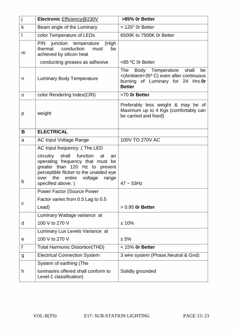
VOL-II(TS) E17- SUB-STATION LIGHTING PAGE 15/ 23
j Electronic Efficiency@230V >85% 0r Better
k Beam angle of the Luminary > 120° 0r Better
l color Temperature of LEDs 6500K to 7500K 0r Better
m
P/N junction temperature (High thermal conduction must be achieved by silicon heat
conducting greases as adhesive <85 ºC 0r Better
n Luminary Body Temperature
The Body Temperature shall be <(Ambient+35º C) even after continuous burning of Luminary for 24 Hrs.0r Better
o color Rendering Index(CRI) >70 0r Better
p weight
Preferably less weight & may be of Maximum up to 4 Kgs (comfortably can be carried and fixed)
B ELECTRICAL
a AC Input Voltage Range 100V TO 270V AC
b
AC Input frequency .( The LED
circuitry shall function at an operating frequency that must be greater than 120 Hz to prevent perceptible flicker to the unaided eye over the entire voltage range specified above. )
47 ~ 53Hz
c
Power Factor (Source Power
Factor varies from 0.5 Lag to 0.5
Lead)
> 0.95 0r Better
d
Luminary Wattage variance at
100 V to 270 V
± 10%
e
Luminary Lux Levels Variance at
100 V to 270 V
± 5%
f Total Harmonic Distortion(THD) < 15% 0r Better
g Electrical Connection System 3 wire system (Phase,Neutral & Gnd)
h
System of earthing (The
luminaries offered shall conform to Level-1 classification)
Solidly grounded

VOL-II(TS) E17- SUB-STATION LIGHTING PAGE 16/ 23
i
There shall be electrical isolation between input and output circuits
of the driver.
C MECHANICAL
a
Construction of Casing High Pressure Die Cast Aluminum. Should be durable for extreme climatic conditions.
b
Finish
Powder Coating and gray/black color and should be durable. The colour should not fade in extreme climate conditions.
c
Heat Sink type (It shall be
designed in such a way that the heat generated within the LED source is efficiently dissipated to the surrounding atmosphere without abnormal rise in temperature. Any debris build up shall not degrade heat dissipation performance of the luminaries.
Aluminium Metal Core PCB
d Lamp Cover Toughened Glass or any suitable material which can be used in the extreme climate and should be durable.
e
Gross Weight and Dimensions (L x W x T) mm of
Luminaries (Efforts shall be made to keep the overall outer dimensions as minimum as possible with out compromising on the performance, mainly thermal management of the luminary )
f Heat Dissipating Area (Luminary Rating wise)
g IP Level –Minimum IP 65
4.0 18W AC DOWN LIGHT
4.1 DATASHEET
4.2 Applications :
Area: Indoor
Purpose: Home and Office Lighting.
4.3 Features:
(1) Optical
Optical pattern meets all standard Home and Office Light Standards.
Uniform illuminance distribution.
(2) Power
Switched mode constant current power supply.

VOL-II(TS) E17- SUB-STATION LIGHTING PAGE 17/ 23
Over-heat, Over-voltage, Over-current protections are provided.
Lightning Protection provided.
(3) Thermal
Luminaire surface temperature is 48°C @ Ta=30°C, the temperature
variation is controlled under 5°C.
Junction temperature is controlled ot 70°C @ Ta=30.
Overheat protection will operate to adjust as the LED module surface
reaches 80°C.
(4) Luminaire
Optimized thermal design to ensure maximum life to LED. The Heat sink
grade aluminium has the highest surface area for efficient heat diffusion and
the entire luminary with Aluminium acts as heat sink.
Dust and water protection design meeting IP65 standards.
Super-high luminaire efficacy.
4.4 DETAILED TECHNICAL SPECIFICATION
I. Electrical Characteristics:
PARAMETER DRIVER RESULT
Input Voltage 160 -300 V AC
Rated Power 18Watt
Maximum Power 21Watt
Efficiency >85%
Power Factor >0.9
Voltage Harmonics (THD) <5%
Current Harmonics (THD) <10%
II. Operating Conditions:
Operating Frequency 100kHz to 200KHz
Operating Temperature Range -25°C to +70°C
Storage Temperature Range -65°C to 125°C
Humidity 95% RH
III.LED Details:
Led Make As per approved vendor
No Of LED’s 12
Led Viewing Angle 120º by using reflector
Colour Temperature Cool White (5500 to 6500K)
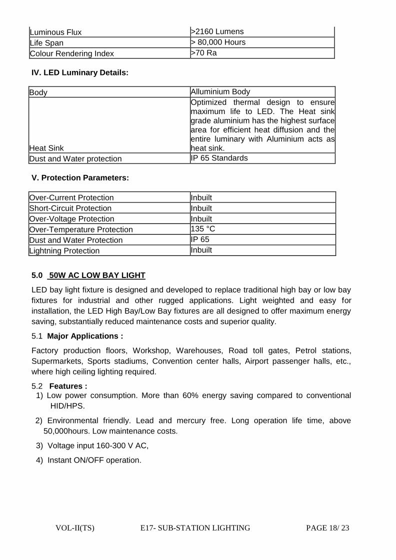
VOL-II(TS) E17- SUB-STATION LIGHTING PAGE 18/ 23
Luminous Flux >2160 Lumens
Life Span > 80,000 Hours
Colour Rendering Index >70 Ra
IV. LED Luminary Details:
Body Alluminium Body
Heat Sink
Optimized thermal design to ensure maximum life to LED. The Heat sink grade aluminium has the highest surface area for efficient heat diffusion and the entire luminary with Aluminium acts as heat sink.
Dust and Water protection IP 65 Standards
V. Protection Parameters:
Over-Current Protection Inbuilt
Short-Circuit Protection Inbuilt
Over-Voltage Protection Inbuilt
Over-Temperature Protection 135 °C
Dust and Water Protection IP 65
Lightning Protection Inbuilt
5.0 50W AC LOW BAY LIGHT
LED bay light fixture is designed and developed to replace traditional high bay or low bay
fixtures for industrial and other rugged applications. Light weighted and easy for
installation, the LED High Bay/Low Bay fixtures are all designed to offer maximum energy
saving, substantially reduced maintenance costs and superior quality.
5.1 Major Applications :
Factory production floors, Workshop, Warehouses, Road toll gates, Petrol stations,
Supermarkets, Sports stadiums, Convention center halls, Airport passenger halls, etc.,
where high ceiling lighting required.
5.2 Features : 1) Low power consumption. More than 60% energy saving compared to conventional
HID/HPS.
2) Environmental friendly. Lead and mercury free. Long operation life time, above
50,000hours. Low maintenance costs.
3) Voltage input 160-300 V AC,
4) Instant ON/OFF operation.
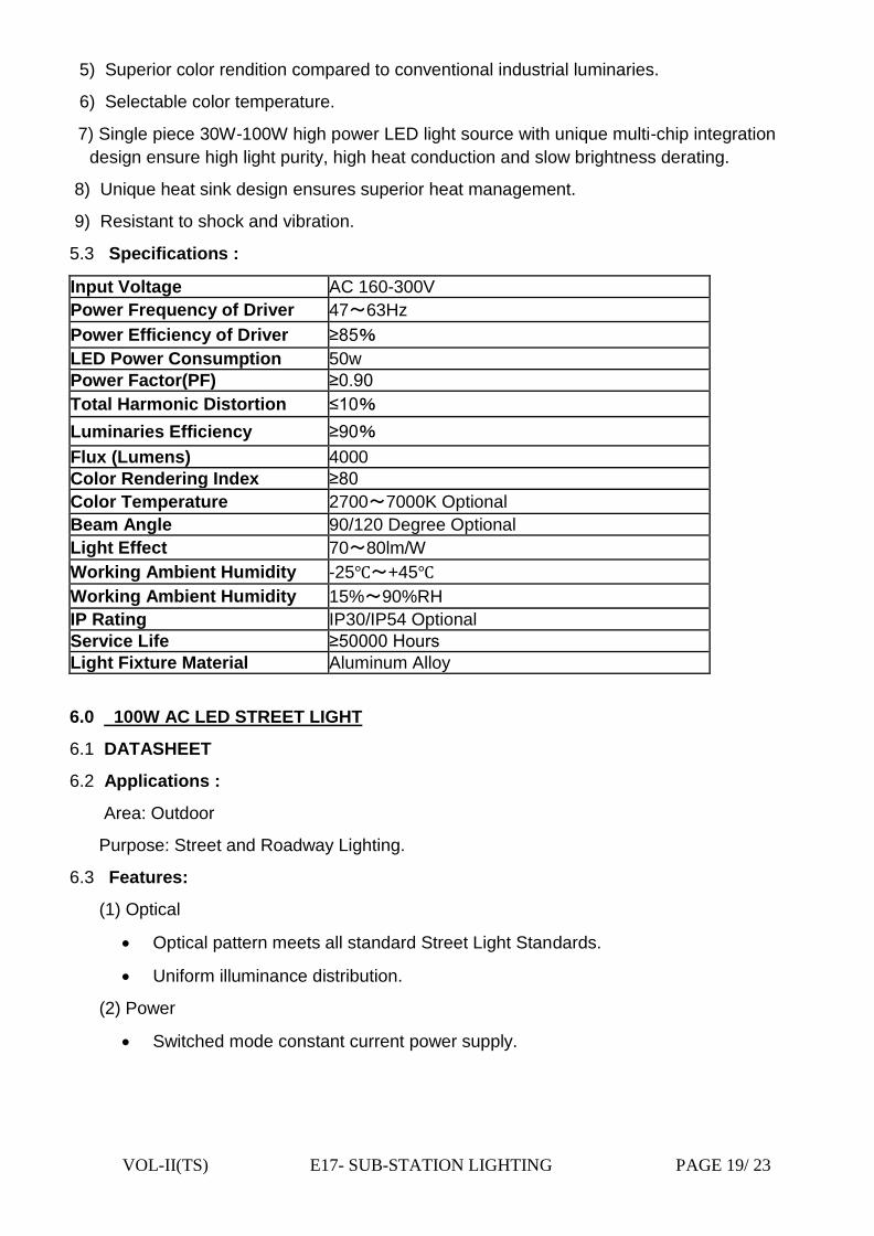
VOL-II(TS) E17- SUB-STATION LIGHTING PAGE 19/ 23
5) Superior color rendition compared to conventional industrial luminaries.
6) Selectable color temperature.
7) Single piece 30W-100W high power LED light source with unique multi-chip integration
design ensure high light purity, high heat conduction and slow brightness derating.
8) Unique heat sink design ensures superior heat management.
9) Resistant to shock and vibration.
5.3 Specifications :
Input Voltage AC 160-300V
Power Frequency of Driver 47~63Hz
Power Efficiency of Driver ≥8 %
LED Power Consumption 50w
Power Factor(PF) ≥ .
Total Harmonic Distortion ≤1 %
Luminaries Efficiency ≥ %
Flux (Lumens) 4000
Color Rendering Index ≥8
Color Temperature 2700~7000K Optional
Beam Angle 90/120 Degree Optional
Light Effect 70~80lm/W
Working Ambient Humidity -25℃~+45℃
Working Ambient Humidity 15%~90%RH
IP Rating IP30/IP54 Optional
Service Life ≥ Hours
Light Fixture Material Aluminum Alloy
6.0 100W AC LED STREET LIGHT
6.1 DATASHEET
6.2 Applications :
Area: Outdoor
Purpose: Street and Roadway Lighting.
6.3 Features:
(1) Optical
Optical pattern meets all standard Street Light Standards.
Uniform illuminance distribution.
(2) Power
Switched mode constant current power supply.

VOL-II(TS) E17- SUB-STATION LIGHTING PAGE 20/ 23
Over-heat, Over-voltage, Over-current protections are provided.
Lightning Protection provided.
(3) Thermal
Luminaries surface temperature is 48°C @ Ta=30°C, the temperature
variation is controlled under 5°C.
Junction temperature is controlled ot 70°C @ Ta=30.
Overheat protection will operate to adjust as the LED module surface
reaches 80°C.
(4) Luminaire
Optimized thermal design to ensure maximum life to LED. The Heat sink
grade aluminium has the highest surface area for efficient heat diffusion and
the entire luminary with Aluminium acts as heat sink.
Dust and water protection design meeting IP65 standards.
Super-high luminaire efficacy.
6.5 DETAILED TECHNICAL SPECIFICATION
Electrical Charatcteristics
PARAMETER PROMPT DRIVER RESULT
Input Voltage 160 -300 VAC
Rated Power 100W
Maximum Power 115W
Efficiency >85%
Power Factor >0.9
Voltage Harmonics (THD) <5%
Current Harmonics (THD) <10%
II. Operating Conditions:
Operating Frequency 100kHz to 200KHz
Operating Temperature Range -25°C to +70°C
Storage Temperature Range -65°C to 125°C
Humidity 95% RH
III. LED Details:
Led Make As per approved vendor
No of LED’s 48-70
Led Viewing Angle 120º by using reflector
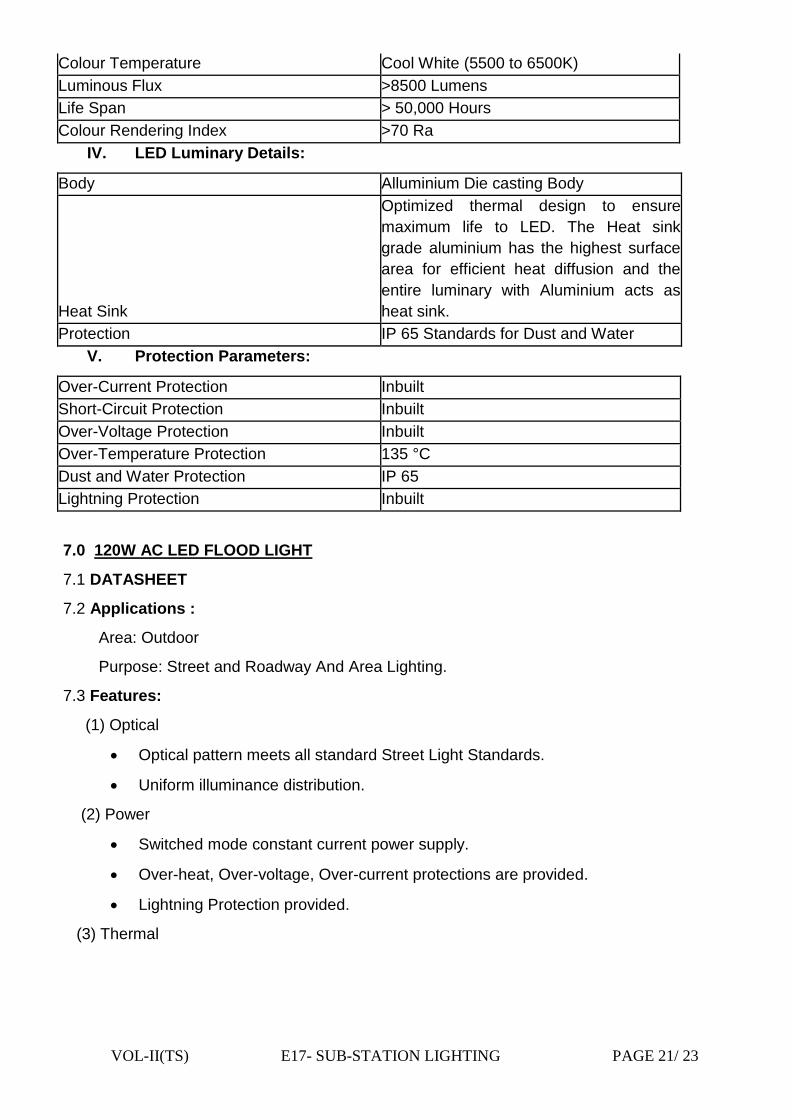
VOL-II(TS) E17- SUB-STATION LIGHTING PAGE 21/ 23
Colour Temperature Cool White (5500 to 6500K)
Luminous Flux >8500 Lumens
Life Span > 50,000 Hours
Colour Rendering Index >70 Ra
IV. LED Luminary Details:
Body Alluminium Die casting Body
Heat Sink
Optimized thermal design to ensure
maximum life to LED. The Heat sink
grade aluminium has the highest surface
area for efficient heat diffusion and the
entire luminary with Aluminium acts as
heat sink.
Protection IP 65 Standards for Dust and Water
V. Protection Parameters:
Over-Current Protection Inbuilt
Short-Circuit Protection Inbuilt
Over-Voltage Protection Inbuilt
Over-Temperature Protection 135 °C
Dust and Water Protection IP 65
Lightning Protection Inbuilt
7.0 120W AC LED FLOOD LIGHT
7.1 DATASHEET
7.2 Applications :
Area: Outdoor
Purpose: Street and Roadway And Area Lighting.
7.3 Features:
(1) Optical
Optical pattern meets all standard Street Light Standards.
Uniform illuminance distribution.
(2) Power
Switched mode constant current power supply.
Over-heat, Over-voltage, Over-current protections are provided.
Lightning Protection provided.
(3) Thermal
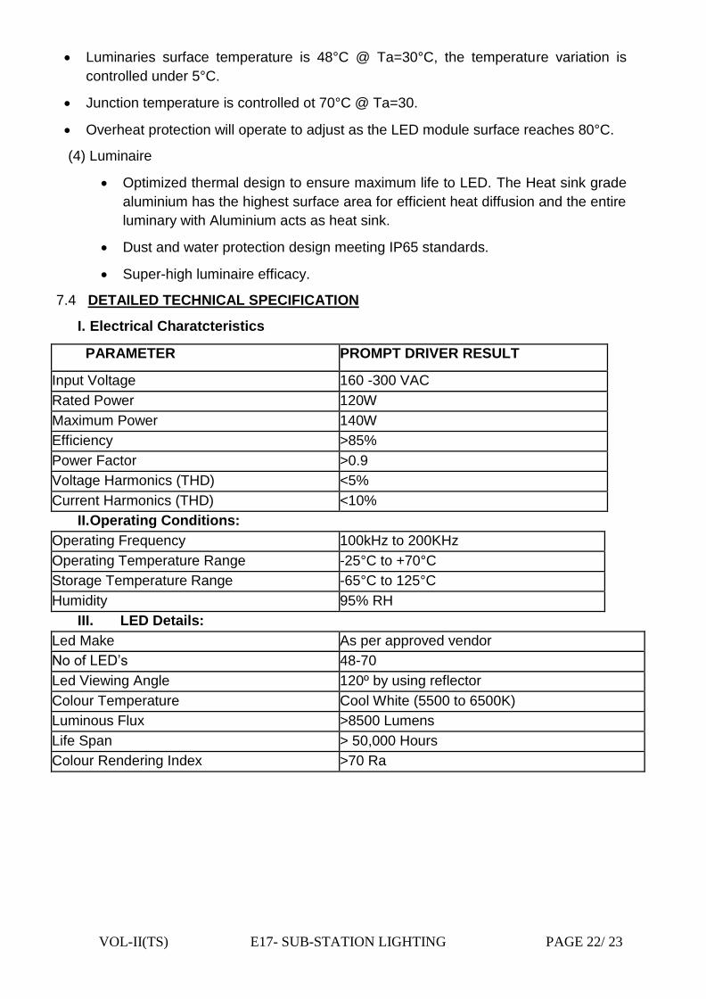
VOL-II(TS) E17- SUB-STATION LIGHTING PAGE 22/ 23
Luminaries surface temperature is 48°C @ Ta=30°C, the temperature variation is
controlled under 5°C.
Junction temperature is controlled ot 70°C @ Ta=30.
Overheat protection will operate to adjust as the LED module surface reaches 80°C.
(4) Luminaire
Optimized thermal design to ensure maximum life to LED. The Heat sink grade
aluminium has the highest surface area for efficient heat diffusion and the entire
luminary with Aluminium acts as heat sink.
Dust and water protection design meeting IP65 standards.
Super-high luminaire efficacy.
7.4 DETAILED TECHNICAL SPECIFICATION
I. Electrical Charatcteristics
PARAMETER PROMPT DRIVER RESULT
Input Voltage 160 -300 VAC
Rated Power 120W
Maximum Power 140W
Efficiency >85%
Power Factor >0.9
Voltage Harmonics (THD) <5%
Current Harmonics (THD) <10%
II. Operating Conditions:
Operating Frequency 100kHz to 200KHz
Operating Temperature Range -25°C to +70°C
Storage Temperature Range -65°C to 125°C
Humidity 95% RH
III. LED Details:
Led Make As per approved vendor
No of LED’s 48-70
Led Viewing Angle 120º by using reflector
Colour Temperature Cool White (5500 to 6500K)
Luminous Flux >8500 Lumens
Life Span > 50,000 Hours
Colour Rendering Index >70 Ra

VOL-II(TS) E17- SUB-STATION LIGHTING PAGE 23/ 23
IV. LED Luminary Details:
Body Alluminium Die casting Body
Heat Sink
Optimized thermal design to ensure maximum
life to LED. The Heat sink grade aluminium has
the highest surface area for efficient heat
diffusion and the entire luminary with Aluminium
acts as heat sink.
Protection IP 65 Standards for Dust and Water
V.Protection Parameters:
Over-Current Protection Inbuilt
Short-Circuit Protection Inbuilt
Over-Voltage Protection Inbuilt
Over-Temperature Protection 135 °C
Dust and Water Protection IP 65
Lightning Protection Inbuilt
NOTE:
The contractor has to design the requirement as per the lux level indicated in Table-1A
above & the said quantity if exceeding the minimum recommended quantity the contractor
has to supply the quantity as required as per the design and should not be less than the
minimum recommended quantity. Minimum Nos of foittings recommended are as below :
Outside Control Room : 1) 120W AC LED – 4nos. 2) 100W AC LED – 06nos.
Inside Control Room : 1) As per the desiogn
Ceiling fan:1400 mm Sweep: 06 Nos
Exhaust fan: 300 mm Sweep:04 Nos
VOL-II(TS) E18 – AIR CONDITIONING PAGE - 1 /3
CHAPTER-E18
TECHNICAL SPECIFICATION FOR
AIR CONDITIONING
VOL-II(TS) E18 – AIR CONDITIONING PAGE - 2 /3
TABLE OF CONTENTS
OF AIR CONDITIONING
NO DESCRIPTION PAGE NO 1.0 General 3
2.0 Scope 3
3.0 Drain type 3
4.0 Specification for Split Air Conditioner units 3

VOL-II(TS) E18 – AIR CONDITIONING PAGE - 3 /3
TECHNICAL SPECIFICATION FOR AIR CONDITIONING SYSTEM
1.0 GENERAL
The scope covers supply, installation, testing and commissioning of Air conditioning system for the control room building.
1.1. Air conditioning requirement for Control room building indicated shall be met by using 6nos. 1.5 Ton each 5 star rated split AC units as per Chapter- E23 (Vendor List).
1.2 Copper refrigerant piping complete with insulation between the indoor and
remote outdoor condensers as required.
2.0 SCOPE:
The scope of the equipment to be furnished and services to be provided under
the contract are outlined herein and the same is to be read in conjunction with
the provision contained. The scope shall be deemed to include all such items
which although not specifically mentioned in the bid documents and/or in
bidders proposal, but are required to make the equipment /system complete
for its safe, efficient, reliable and trouble free operation of hermetically sealed.
3.0 Drain pipe PVC drains piping from the indoor units up to the nearest drain point to be
done. 3.1 Power and control cables between the indoor unit and out door unit and
Earthing are to be provided. 3.2 GI brackets for outdoor condensing unit and proper earthing. 4.0 Specification for Split AC units.
The split AC units will be complete with indoor evaporator unit, outdoor
condensing units and cordless remote control units
Outdoor units shall comprise of hermetically sealed reciprocating/rotary
compressors mounted on vibration isolators, propeller type axial flow fans and
copper tube aluminium finned coils assembled in a sheet metal. The casing and
the total unit shall be properly treated and shall be weather proof type. They
shall be compact in size and shall have horizontal discharge of air.
The indoor unit shall be high wall type. The indoor unit shall be compact and
shall have elegant appearance. They shall have low noise centrifugal blowers
driven by special motors and copper tube aluminium finned cooling coils.
Removable and washable polypropylene filters shall be provided. They shall be
complete with multifunction cordless remote control unit with special features
like programmable timer, sleep mode and softy dry mode etc.

VOL-II(TS) E19-TESTING EUIPMENT PAGE 1/ 10
CHAPTER - E19
TECHNICAL SPECIFICATION
FOR TESTING INSTRUMENTS AND MAINTENANCE KITS
OTHER TOOLS & PLANTS
&
OFFICE FURNITURE
VOL-II(TS) E19-TESTING EUIPMENT PAGE 2/ 10
TABLE OF CONTENTS
OF
TESTING INSTRUMENTS,T&P AND OFFICE FURNITURE
NO DESCRIPTION PAGE NO
1.0 General 3
2.0 Training 3
3.0 Climatic Condition 3
4.0 100 KV Transformer Oil Breakdown Voltage Test Set 3
5.0 Insulation Resistance Tester (Megger) 4
6.0 Oil Sampling Bottle 5
7.0 Relay tools kits (Also refer the specification of PCM) 5
8.0 SF6 Gas leak DETECTOR 6
9.0 Digital Multimeter 6
10.0 Digital clamp-on- meter (AC) 6
11.0 Digital Earth Tester 6
12.0 Discharge Rods 7
13.0 Rubber Hand Gloves 7
14.0 Portable Emergency Light 7
15.0 Schedule of requirements of maintenance TESTING equipment 8
16.0 Other TOOLS AND PLANTS (T&P’S) requirement 8
17.0 Office Furniture 10

VOL-II(TS) E19-TESTING EUIPMENT PAGE 3 /10
1.0 GENERAL
The testing and maintenance equipment covered here are generally meant for
carrying out testing and measurement at site and shall be complete with all materials
and accessories. These shall be robust in design, so that they give accurate results
even in adverse site conditions.
All equipment furnished shall be of reputed make, type tested and shall be subjected
to acceptance and routine tests in accordance with the requirements stipulated under
respective equipment specification.
At least two sets of descriptive leaflets, catalogues, outline drawing, principles of
operation etc. shall be sent along with the offer, for all the equipment offered. Weight
and dimensions of items should also be mentioned.
Four sets of inspection and calibration report, operation and maintenance manual
shall be sent along with Despatch documents. One set will be kept inside the
equipment.
In the event of bidder offering equipment manufactured by different manufacturers, it
will be his responsibility to fully co-ordinate the activities of each manufacturer in such
a way that the complete equipment contracted for, is manufactured, supplied and
guaranteed for successful operation.
2.0 TRAINING Necessary training shall be provided to Employer's personnel for using and
maintaining the equipment at Employer's premises for the testing equipment supplied
if required.
3.0 CLIMATIC CONDITION The equipment covered under this specification shall be suitable for operation under
climatic condition stated at chapter-E3 of the technical specification. The offered
equipment as such shall be suitable for satisfactory operation under the tropical
climate.
4.0 100 KV TRANSFORMER OIL BREAKDOWN VOLTAGE TEST SET The equipment offered shall be suitable for determination of electric strength
(breakdown voltage) of insulating oil upto 100 KV to IS:335 (latest thereof) when
measured in accordance with IS:6792.
The test cell shall be as per IS:6792 suitable for BDV upto 100 KV without external
flashover.
The unit shall be of composite type having control unit and high voltage transformer
in a common cabinet with necessary partition. HV chamber interlocking and zero start
interlocking shall be provided.
The unit shall have motorised drive to increase voltage linearly as per the rate
specified in IS:6792.Provision should also be available for manual increase of

VOL-II(TS) E19-TESTING EUIPMENT PAGE 4 /10
voltage. The unit shall be complete with test cell, stirrer and "GO" and "NO GO"
gauge for adjusting the gap.
The instrument shall have
1) Operating temperature: 0 – C
2) Humidity > 90% and nearly equals to 99%
3) Low/ High level interlocking for drive motor. Earth open interlocking,reverse
interlocking.
4) Protection: Quick acting D.C relay to isolate the H.T.
5) Test cup: The test cup with cover shall be made of Methyle
Mathacrylate(Acrylic) having oil between 300 and 500 ml, with adjustable and
removable mushroom head and ground to adjust the electrode gap distance.
6) Motorised and manual operation.
7) A linear scaled A.C rectifier voltmeter marked kV to measure output voltage.
8) Shall have magnetic strainer provision for removing the bubbles.
The equipment shall be suitable for operation at 240 volts 50 Hz. Single phase
AC supply.
5.0 INSULATION RESISTANCE TESTER (MEGGER) The equipment offered shall be used for measurement of insulation resistance of
electrical equipment.
5.1 Technical Requirements
a) Rated voltage selection : 1, 2, 3, 4, and 5 kV (DC Volts)
b) Rated resistance (megohms) 0 to 100000 multi-range type. Resistance range for each rated voltage shall be indicated in the offer.
c) Type Portable, compact and direct reading type of multi-voltage with multi-rated resistance ranges. The tester shall be suitable for hand operation as well as operation by a continuously rated motor with AC mains supply of 230V, single phase, 50 Hz.
d) Ambient temperature to C
e) Infinity adjustment There should be provision
f) leather carrying case The instrument shall be supplied with 7 metre long mains leads (shall have insulation level as per required) and leather carrying case.
g) Standards The tester shall generally comply with the requirements of IS:2992-1987 and IS:11994-1986 and latest.

VOL-II(TS) E19-TESTING EUIPMENT PAGE 5 /10
h) Preferable make The equipment offered shall be of reputed make preferably Megger/ AVO International make or equivalent (on approval of OPTCL)
i) Other required spec. High voltage indication by LED for user safety
j) Auto discharge of capacitive load with indication after the IR test.
k) Recessed terminals and shrouded leads for enhanced user safety.
l) Linear and accurate reading
m) Protected against accidental connection to 230/440 V AC supplies.
n) Portable and light weight suitable for field and Lab use.
5.2 Test Requirements Type test certificate for all ten tests as per Cl.11.1 of IS:2992.
All routine tests as per Cl.11.3 of IS:2992 shall be conducted.
6.0 OIL SAMPLING BOTTLE Oil Sampling bottles shall be suitable for collecting oil samples from transformers, for
testing of the oils (BDV, Dissolved Gas Analysis, resistivity etc). Bottles shall be
robust enough, so that no damage occurs during frequent transportation of samples
from site to laboratory.
Oil sampling bottles shall be made of stainless steel having a capacity of 1 litre.
Oil sampling bottles shall be capable of being sealed gas-tight and shall be fitted with
cocks on both ends.
The design of bottle and seal shall be such that loss of hydrogen shall not exceed 5%
per week.
An impermeable oil-proof, plastic or rubber tube of about 5 mm diameter, and of
sufficient length shall also be provided with each bottle along with suitable
connectors to fit the tube on to the oil sampling valve of the equipment and the oil
collecting bottles respectively.
7.0 RELAY TOOLS KITS
The relay tool kit shall consist of the following minimum items:
1. Test plugs for use with testing equipment
2. Special type test plugs for using with modular type cases
3. Screw driver set with multiple fixing feature
4. Long nose pliers
5. Wire cutting pliers and stripper

VOL-II(TS) E19-TESTING EUIPMENT PAGE 6 /10
6. Ordinary pliers
7. Adjustable wrench
8. Soldering irons of
o) Watts rating - 1 No.
p) Watts rating - 1 No.
q) Watts rating - 1 No.
9. De-soldering pump
10. Printed Circuit Card-extender; Printed circuit card - `Puller' Suitable for all supplied relays
11. Test leads (Pair with 2 Mts. length) - 1 set
12. Shorting plugs, `pistol' prods (2 Nos.) - 1 set
8.0 SF6 GAS LEAK DETECTOR The SF6 gas leak detector shall meet the following requirements
The detector shall be free from induced voltage effects.
The sensing probe shall be such that it can reach all the points on the breaker where
leakage is to be sensed .Latest standard in this effect may be followed.
9.0 Digital Multimeter The digital multi meter shall have a LCD screen for displaying 3 and 3/4 digits and
having auto ranging facility. Instrument shall have single rotary selection switch.
Instrument shall have automatic polarity, low battery and over range indication and a
range of 0.1mV to 1000V DC, 0.1mV to 750V AC, 0 -10A DC , 0-10 A ,AC and 0-10
mega ohm. Instrument shall have auto selection of AC/DC ampere and AC/DC
Voltage. It shall have auto power off and data hold facility.Instrument shall have
rugged casing and other measurement facilities (resistance, diode, continuity etc
measurement) as per standard.
10.0 Digital clamp-on- meter: (AC) The digital clamp meter shall have LCD screen for displaying 3 and 3/4 digits,
multifunction, 1000 Ampere range of AC current at (i) 0.01 Amp to 20 Amp, (ii) to
200Amp and (iii) to 1000Amp; AC/DC voltage range 0.01 V to 200V and in the other
scale up to 1000V, Provision of measurement of resistance up to 0 – 10 mega ohms
at different scale selection and also other facilities. Instrument shall have single rotary
selection switch. It shall have auto power off and data hold facility. Instrument shall
have rugged casing and other measurement facilities (resistance, diode, continuity
etc measurement) as per standard.
11.0 Digital Earth Tester. The digital earth tester shall have 4 points ,three range (0 .01 ohms to 20 ohms, 200
ohms and up to 2000 ohms) type. Battery operated type instrument.3 and 1/2 digit
LCD display with maximum reading 1999 ohms. Instrument shall have rechargeable
internal Ni-MH Battery. Instrument shall be of 4 wire soil resistivity measurement.
Type tested as per IS-9223.Instrument shall have low bat indication and data hold
facility. Instrument shall have over range indication. Single, measuring time below 1
minute.Instrument shall consist of required nos of standard length of spikes

VOL-II(TS) E19-TESTING EUIPMENT PAGE 7 /10
(minimum 1 mtr), flexible copper PVC wires of required length (minimum length shall
be 30mtrs two pieces and 15 mtrs two pieces, and two more pieces for connecting
to the instrument), one no. suitable hammer for hammering the spike for inserting
into the earth. There shall be crocodile clamps on one side of each wire and round
clips on the other side for connecting to the instrument.
12.0 Discharge Rods: Discharge rods shall be good quality and as per the latest relevant standard.
Required length of PVC good insulation flexible copper cable, required clamp
connected at the end of wire shall be connected. The top portion of the discharge
rod shall be adjustable to fit in for proper gripping by screwing from the bottom side.
The entire handle shall be of latest insulating materials for the safety of the user.
The discharge rod shall be reliable, durable and shall meet the safety requirement of
the users.
13.0 Rubber Hand Gloves: Good quality rubber gloves for using during operation of isolators and earth switch.
Latest standard for the rubber gloves shall be followed. The gloves shall be reliable,
durable and shall meet the safety requirement of the users.
14.0 Portable Emergency Light: Reputed make (BPL/CGL/Bajaj) portable emergency light, having twin tube,
shall be supplied to each Sub-station. It shall have chargeable battery (durable) and
having provision of selection switch for selecting single or double tube. It shall have
chargeable feature during not in use and automatically switch on in the event of
power failure. CFL tubes are preferred. It shall have provision of wall hanging/table
mounting and shall be durable one. Latest standard in this effect shall be followed.
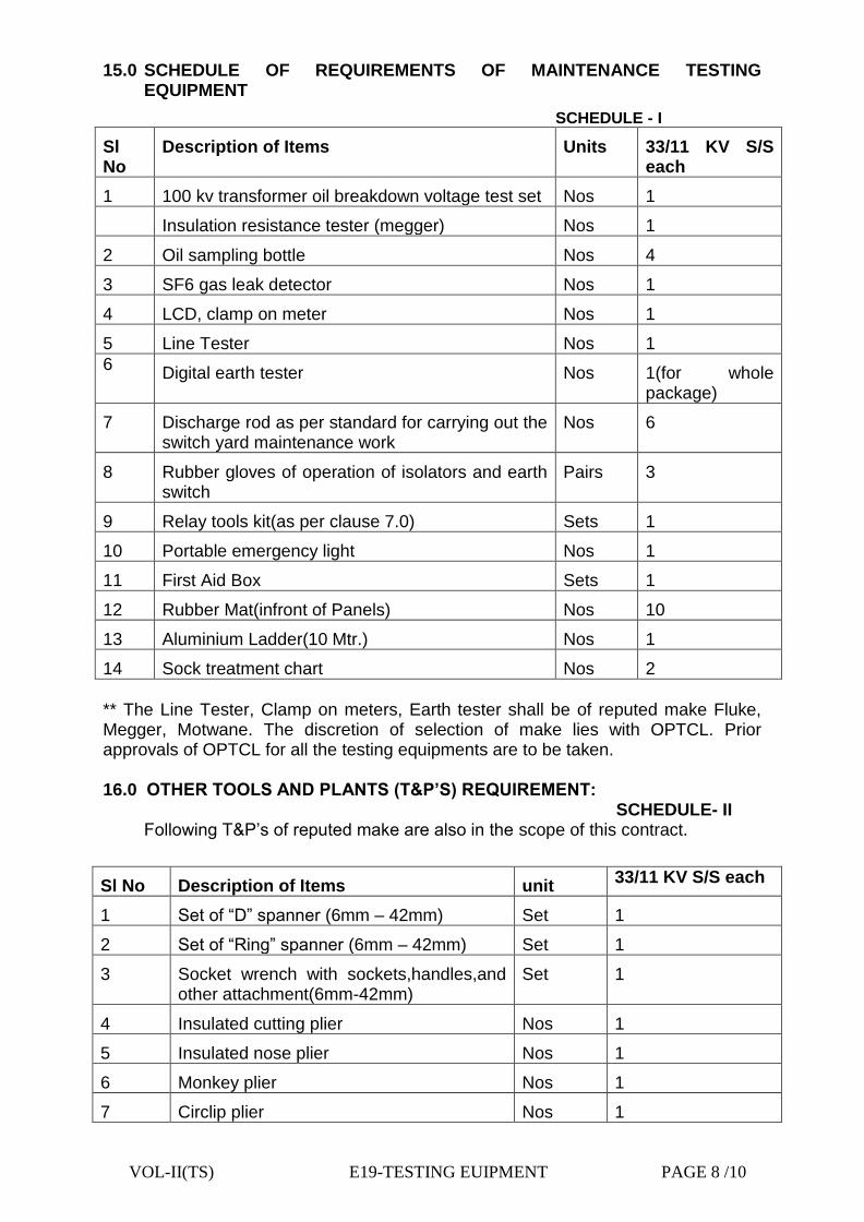
VOL-II(TS) E19-TESTING EUIPMENT PAGE 8 /10
15.0 SCHEDULE OF REQUIREMENTS OF MAINTENANCE TESTING EQUIPMENT
SCHEDULE - I
Sl No
Description of Items Units 33/11 KV S/S each
1 100 kv transformer oil breakdown voltage test set Nos 1
Insulation resistance tester (megger) Nos 1
2 Oil sampling bottle Nos 4
3 SF6 gas leak detector Nos 1
4 LCD, clamp on meter Nos 1
5 Line Tester Nos 1
6 Digital earth tester
Nos 1(for whole package)
7 Discharge rod as per standard for carrying out the switch yard maintenance work
Nos 6
8 Rubber gloves of operation of isolators and earth switch
Pairs 3
9 Relay tools kit(as per clause 7.0) Sets 1
10 Portable emergency light Nos 1
11 First Aid Box Sets 1
12 Rubber Mat(infront of Panels) Nos 10
13 Aluminium Ladder(10 Mtr.) Nos 1
14 Sock treatment chart Nos 2
** The Line Tester, Clamp on meters, Earth tester shall be of reputed make Fluke, Megger, Motwane. The discretion of selection of make lies with OPTCL. Prior approvals of OPTCL for all the testing equipments are to be taken. 16.0 OTHER TOOLS AND PLANTS (T&P’S) REQUIREMENT: SCHEDULE- II Following T&P’s of reputed make are also in the scope of this contract.
Sl No Description of Items unit 33/11 KV S/S each
1 Set of “D” spanner (6mm – 42mm) Set 1
2 Set of “Ring” spanner (6mm – 42mm) Set 1
3 Socket wrench with sockets,handles,and other attachment(6mm-42mm)
Set 1
4 Insulated cutting plier Nos 1
5 Insulated nose plier Nos 1
6 Monkey plier Nos 1
7 Circlip plier Nos 1

VOL-II(TS) E19-TESTING EUIPMENT PAGE 9 /10
8 Pipe wrench
a)12 inch – 1 no b)18 inch – 1 no
Set
1
9 Sly wrench
a)12 inch – 1 no b)18 inch – 1 no
Set
1
10 Insulated handle screw drivers of different sizes as per required
a) 12inch plain head – 1 no
b) 8inch plain head – 1 no
c) 12inch star head – 1 no
d) small size6inch plain and star head – 1
each
e) Complete set of different head in one
box/set -1set
Set 1
11 “L”-N keys set of different sizes in one box/set
Set 1
12 M.S Files(12inch and 6inch sizes) Round files and flat files-one each of different sizes)
set 1
13 Hammar with handle a)1 lb – 1 no b)1/2 lb-1 no c)2 lb-1 no
Set 1
14 Crow bar a)5 ft – 1no b)3ft- 1no
set 1
15 Steel scale(12inch) Nos 1
16 Steel tape a)5 mtrs-1 no b)30mtrs-1 no
Set 1
17 Oil cane Nos 1
18 Spirit level (8inch) No 1
19 Plumb head with string and attachment No 1
20 Maintenance safety belt with all attachment and helmets(complete one set)
Set 3
** All the T&P’s shall be of Taparia/ Gedore/ Tata make. The hand drill and vacuum cleaner shall be of Rallies wolf and Eureka Forbes make.

VOL-II(TS) E19-TESTING EUIPMENT PAGE 10 /10
17.0 OFFICE FURNITURE:
Supply and installations of the furnitures for office & customer care center are in the scope of this contract. All the furniture shall be of Godrej make. Details of the scope of supply are as indicated below:
SCHEDULE – III.
Sl No
Description of Items unit 33/11 KV S/S each
Office Customer Care
1 5ftX3ft table with drawer both sides Nos 1 1
2 Computer table suitable keeping monitor,CPU,UPS and printer with two nos revolving arm chair suitable for computer use.
Set 1 --
3 Revolving, adjustable(height) chairs with arm
Nos 1 1
4.a “S” type steel chairs with arm Nos 4 --
4.b “S” type steel chair Fixed by GI Pipe (5nos. in one line)
Set -- 2
(1X5 in one set)
6 6ft height steel almirah (only with selves) for keeping records and other valuable items
Nos 1 --
7 4ft steel rack (Five selves) for keeping the files and other items
Nos 1 --
VOL-II(TS) E-20 – MANDATORY SPARE PARTS PAGE - 1/ 5
CHAPTER- E-20
MANDATORY SPARE PARTS

VOL-II(TS) E-20 – MANDATORY SPARE PARTS PAGE - 2/ 5
MANDATORY SPARES REQUIRED FOR AIS
FOR SUB-STATION
1 For 33kV Equipments Unit
1.1 Complete VCB Trolley Nos
1.2 Vacuum interrupter bottles Nos
1.3 Tripping coil Nos
1.4 Closing coil Nos
1.5 Set of spring charging limit switches Nos
1.6 CT Nos
1.7 Surge Arrester Nos
2 For 11kV Equipment
2.1 Complete VCB Trolley Nos
2.2 Vacuum interrupter bottles Nos
2.3 Tripping coil Nos
2.4 Closing coil Nos
2.5 Set of spring charging limit switches Nos
2.6 CT for Line Feeder Nos
2.7 Surge Arrester Nos
3 Common S/s Materials for one Package
3.1 VCB mechanism without Interrupter Nos
3.2 Spring charging motor Nos
3.3 33 kV 300 mm2 1-Core Cable joint kit Out door type Nos
3.4 11 kV 400 mm2 1-Core Cable joint kit Out door type Nos
3.5 11 kV 300 mm2 1-Core Cable joint kit Out door type Nos
3.6 33 kV Transformer Bushing Nos
3.7 11 kV Transformer Bushing Nos
3.8 Bucholtz Relay Nos
3.9 Differential Relay set Nos
3.10 Over current and Earth fault Relay set Nos
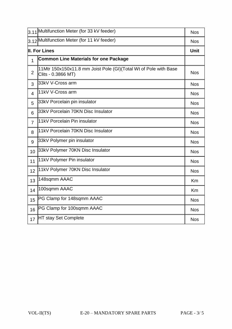
VOL-II(TS) E-20 – MANDATORY SPARE PARTS PAGE - 3/ 5
3.11 Multifunction Meter (for 33 kV feeder) Nos
3.12 Multifunction Meter (for 11 kV feeder) Nos
II. For Lines Unit
1 Common Line Materials for one Package
2 11Mtr 150x150x11.8 mm Joist Pole (GI)(Total Wt of Pole with Base Clits - 0.3866 MT) Nos
3 33kV V-Cross arm Nos
4 11kV V-Cross arm Nos
5 33kV Porcelain pin insulator Nos
6 33kV Porcelain 70KN Disc Insulator Nos
7 11kV Porcelain Pin insulator Nos
8 11kV Porcelain 70KN Disc Insulator Nos
9 33kV Polymer pin insulator Nos
10 33kV Polymer 70KN Disc Insulator Nos
11 11kV Polymer Pin insulator Nos
12 11kV Polymer 70KN Disc Insulator Nos
13 148sqmm AAAC Km
14 100sqmm AAAC Km
15 PG Clamp for 148sqmm AAAC Nos
16 PG Clamp for 100sqmm AAAC Nos
17 HT stay Set Complete Nos

VOL-II(TS) E-20 – MANDATORY SPARE PARTS PAGE - 4/ 5
MANDATORY SPARES REQUIRED FOR GIS
MANDATORY SPARE PARTS Unit
I. FOR SUB-STATION
1 For 33kV Equipments
1.1 Separate motors for VCB, isolator and earth switch (set consisting of one motor of each type)
Set
1.2 Tripping coil and closing coil (one set consisting of one of each coil) Set
1.3 Vacuum bottles Nos
1.4 MCB, auxiliary contactor, auxilliary switch (one set containing one of each item)
Set
1.5 CT Nos
1.6 Thermal Gas density switch Nos
2 For 11kV Equipments
2.1 Complete VCB Trolley Nos
2.2 Vacuum interrupter bottles Nos
2.3 Tripping coil Nos
2.4 Closing coil Nos
2.5 Spring charging motor with spring charging limit switches Nos
2.6 CT for Line Feeder Nos
2.7 Surge Arrester Nos
3 Common S/s Materials for one Package
3.1 33 kV Indoor PT (one set consisting of three phases) Set
3.2 33 kV surge arrester Nos
3.3 33 kV 400 mm2 1-Core Cable joint kit Out door type Nos
3.4 33 kV 400 mm2 1-Core Cable joint kit In-door type Nos
3.5 33 kV 400 mm2 3-Core Cable joint kit Out door type Nos
3.6 11 kV 400 mm2 1-Core Cable joint kit Out door type Nos
3.7 11 kV 630 mm2 1-Core Cable joint kit Out door type Nos
3.8 11 kV 400 mm2 1-Core Cable joint kit In-door type Nos
3.9 11 kV 630 mm2 1-Core Cable joint kit In-door type Nos
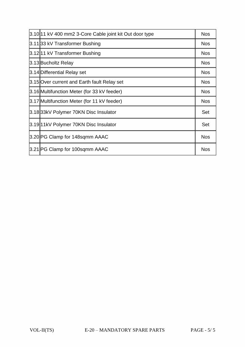
VOL-II(TS) E-20 – MANDATORY SPARE PARTS PAGE - 5/ 5
3.10 11 kV 400 mm2 3-Core Cable joint kit Out door type Nos
3.11 33 kV Transformer Bushing Nos
3.12 11 kV Transformer Bushing Nos
3.13 Bucholtz Relay Nos
3.14 Differential Relay set Nos
3.15 Over current and Earth fault Relay set Nos
3.16 Multifunction Meter (for 33 kV feeder) Nos
3.17 Multifunction Meter (for 11 kV feeder) Nos
3.18 33kV Polymer 70KN Disc Insulator Set
3.19 11kV Polymer 70KN Disc Insulator Set
3.20 PG Clamp for 148sqmm AAAC Nos
3.21 PG Clamp for 100sqmm AAAC Nos