technical specification fluxus g721st · 2019-11-07 · technical specification fluxus g721st...
TRANSCRIPT

Technical specification
FLUXUS G721ST
TSFLUXUS_G721STV1-0EN_Leu, 2019-11-01
Features
• Exact and highly reliable measurement of saturated and super-heated steam for temperatures up to max. 180 °C by means of the clamp-on principle
• Physical quantities volumetric flow rate and mass flow rate available in a transmitter without additional steam calculator
• Installation and start-up do not require any pipe work and are carried out without any process interruptions and cooling down of the steam system
• Non-invasive, wear-free and pressure constant measurement
• Maintenance-free acoustic coupling using permanent coupling foil
• High measurement accuracy even at very low as well and high flow rates and independent of the flow direction (bidirectional)
• Automatic loading of calibration data and transducer recogni-tion
• Bidirectional communication and support of common bus tech-nologies (Modbus, Profibus PA, Foundation Fieldbus, BACnet)
• Advanced self-diagnosis and possibilities for event-based trig-gering of data recording for the supervision and control of criti-cal processes
• Transmitter and transducers are separately calibrated (trace-able to national standards)
• The measurement is zero point stable and drift free
Applications
• Food and beverage industry
• Pharmaceutical industry
• Chemical industry
• Manufacturing industries
FLUXUS G721ST-****A
FLUXUS G721ST-****S
Variofix L
Steam ultrasonic flowmeter for permanent installation
Transmitter for permanent outdoor wall or pipe mounting

FLUXUS G721ST Technical specification
2019-11-01, TSFLUXUS_G721STV1-0EN_Leu2
Table of contents
Function . . . . . . . . . . . . . . . . . . . . . . . . . . . . . . . . . . . . . . . . . . . . . . . . . . . . . . . . . . . . . . . . . . . . . . . . . . . . . . . . . . . . . . . 3Measurement principle . . . . . . . . . . . . . . . . . . . . . . . . . . . . . . . . . . . . . . . . . . . . . . . . . . . . . . . . . . . . . . . . . . . . . . . . . . . . . 3Calculation of volumetric flow rate . . . . . . . . . . . . . . . . . . . . . . . . . . . . . . . . . . . . . . . . . . . . . . . . . . . . . . . . . . . . . . . . . . . . 3Calculation of mass flow. . . . . . . . . . . . . . . . . . . . . . . . . . . . . . . . . . . . . . . . . . . . . . . . . . . . . . . . . . . . . . . . . . . . . . . . . . . . 4Number of sound paths . . . . . . . . . . . . . . . . . . . . . . . . . . . . . . . . . . . . . . . . . . . . . . . . . . . . . . . . . . . . . . . . . . . . . . . . . . . . 4Typical measurement setup . . . . . . . . . . . . . . . . . . . . . . . . . . . . . . . . . . . . . . . . . . . . . . . . . . . . . . . . . . . . . . . . . . . . . . . . . 5
Transmitter . . . . . . . . . . . . . . . . . . . . . . . . . . . . . . . . . . . . . . . . . . . . . . . . . . . . . . . . . . . . . . . . . . . . . . . . . . . . . . . . . . . . . 6Technical data . . . . . . . . . . . . . . . . . . . . . . . . . . . . . . . . . . . . . . . . . . . . . . . . . . . . . . . . . . . . . . . . . . . . . . . . . . . . . . . . . . . 6saturated steam pressure curve . . . . . . . . . . . . . . . . . . . . . . . . . . . . . . . . . . . . . . . . . . . . . . . . . . . . . . . . . . . . . . . . . . . . . 7Dimensions. . . . . . . . . . . . . . . . . . . . . . . . . . . . . . . . . . . . . . . . . . . . . . . . . . . . . . . . . . . . . . . . . . . . . . . . . . . . . . . . . . . . . . 82" pipe mounting kit . . . . . . . . . . . . . . . . . . . . . . . . . . . . . . . . . . . . . . . . . . . . . . . . . . . . . . . . . . . . . . . . . . . . . . . . . . . . . . . 9Terminal assignment . . . . . . . . . . . . . . . . . . . . . . . . . . . . . . . . . . . . . . . . . . . . . . . . . . . . . . . . . . . . . . . . . . . . . . . . . . . . . 10
Transducers . . . . . . . . . . . . . . . . . . . . . . . . . . . . . . . . . . . . . . . . . . . . . . . . . . . . . . . . . . . . . . . . . . . . . . . . . . . . . . . . . . . 11Transducer selection . . . . . . . . . . . . . . . . . . . . . . . . . . . . . . . . . . . . . . . . . . . . . . . . . . . . . . . . . . . . . . . . . . . . . . . . . . . . . 11Technical data . . . . . . . . . . . . . . . . . . . . . . . . . . . . . . . . . . . . . . . . . . . . . . . . . . . . . . . . . . . . . . . . . . . . . . . . . . . . . . . . . . 12
Transducer mounting fixture. . . . . . . . . . . . . . . . . . . . . . . . . . . . . . . . . . . . . . . . . . . . . . . . . . . . . . . . . . . . . . . . . . . . . . 13
Coupling materials for transducers . . . . . . . . . . . . . . . . . . . . . . . . . . . . . . . . . . . . . . . . . . . . . . . . . . . . . . . . . . . . . . . . 14
Damping coat . . . . . . . . . . . . . . . . . . . . . . . . . . . . . . . . . . . . . . . . . . . . . . . . . . . . . . . . . . . . . . . . . . . . . . . . . . . . . . . . . . 15
Connection systems . . . . . . . . . . . . . . . . . . . . . . . . . . . . . . . . . . . . . . . . . . . . . . . . . . . . . . . . . . . . . . . . . . . . . . . . . . . . 16
Junction box . . . . . . . . . . . . . . . . . . . . . . . . . . . . . . . . . . . . . . . . . . . . . . . . . . . . . . . . . . . . . . . . . . . . . . . . . . . . . . . . . . . 17Technical data . . . . . . . . . . . . . . . . . . . . . . . . . . . . . . . . . . . . . . . . . . . . . . . . . . . . . . . . . . . . . . . . . . . . . . . . . . . . . . . . . . 17Dimensions. . . . . . . . . . . . . . . . . . . . . . . . . . . . . . . . . . . . . . . . . . . . . . . . . . . . . . . . . . . . . . . . . . . . . . . . . . . . . . . . . . . . . 172" pipe mounting kit . . . . . . . . . . . . . . . . . . . . . . . . . . . . . . . . . . . . . . . . . . . . . . . . . . . . . . . . . . . . . . . . . . . . . . . . . . . . . . 18
Clamp-on temperature probe (optional). . . . . . . . . . . . . . . . . . . . . . . . . . . . . . . . . . . . . . . . . . . . . . . . . . . . . . . . . . . . . 19Technical data . . . . . . . . . . . . . . . . . . . . . . . . . . . . . . . . . . . . . . . . . . . . . . . . . . . . . . . . . . . . . . . . . . . . . . . . . . . . . . . . . . 19Fixation. . . . . . . . . . . . . . . . . . . . . . . . . . . . . . . . . . . . . . . . . . . . . . . . . . . . . . . . . . . . . . . . . . . . . . . . . . . . . . . . . . . . . . . . 19Junction box . . . . . . . . . . . . . . . . . . . . . . . . . . . . . . . . . . . . . . . . . . . . . . . . . . . . . . . . . . . . . . . . . . . . . . . . . . . . . . . . . . . . 20

Technical specification FLUXUS G721ST
3TSFLUXUS_G721STV1-0EN_Leu, 2019-11-01
Function
Measurement principleThe transducers are mounted on the pipe which is completely filled with the fluid. The ultrasonic signals are emitted alter-nately by a transducer and received by the other. The physical quantities are determined from the transit times of the ultra-sonic signals.
As the fluid where the ultrasound propagates is flowing, the transit time of the ultrasonic signal in flow direction is shorterthan the one against the flow direction.
The transit time difference Δt is measured and allows the flowmeter to determine the average flow velocity along the prop-agation path of the ultrasonic signals. A flow profile correction is then performed in order to obtain the area averaged flowvelocity, which is proportional to the volumetric flow rate.
The integrated microprocessors control the entire measuring cycle. The received ultrasonic signals are checked for mea-surement usability and evaluated for their reliability. Noise signals are eliminated.
Calculation of volumetric flow rate = kRe · A · ka ·
where
Path of the ultrasonic signal in the flowing fluid
Transit time difference Δt
- volumetric flow rate
kRe - fluid mechanics calibration factor
A - cross-sectional pipe area
ka - acoustical calibration factor
Δt - transit time difference
tγ - average of transit times in the fluid
Δtt0
Vꞏ t2 t-----------
Vꞏ

FLUXUS G721ST Technical specification
2019-11-01, TSFLUXUS_G721STV1-0EN_Leu4
Calculation of mass flowThe mass flow is calculated on the base of operating density and volume flow:
= ρ .
The operating density of the fluid is calculated as the function of pressure and temperature of the fluid:
ρ = f(p, T)
where
Number of sound pathsThe number of sound paths is the number of transits of the ultrasonic signal through the fluid in the pipe. Depending on thenumber of sound paths, the following methods of installation exist:
• reflection arrangementThe number of sound paths is even. The transducers are mounted on the same side of the pipe. Correct positioning of the transducers is easier.
• diagonal arrangementThe number of sound paths is odd. The transducers are mounted on opposite sides of the pipe. In the case of a high sig-nal attenuation by the fluid, pipe and coatings, diagonal arrangement with 1 sound path will be used.
The preferred method of installation depends on the application. While increasing the number of sound paths increasesthe accuracy of the measurement, signal attenuation increases as well. The optimum number of sound paths for the pa-rameters of the application will be determined automatically by the transmitter.
As the transducers can be mounted with the transducer mounting fixture in reflection arrangement or diagonal arrange-ment, the number of sound paths can be adjusted optimally for the application.
a - transducer distance
ρ - operating density
p - fluid pressure
T - fluid temperature
- mass flow rate
- volumetric flow rate
Reflection arrangement, number of sound paths: 2
Diagonal arrangement, number of sound paths: 3
Diagonal arrangement, number of sound paths: 1 Diagonal arrangement, number of sound paths: 1, negative transducer distance
mꞏ Vꞏ
mꞏ
Vꞏ
a
a
a > 0 a < 0

Technical specification FLUXUS G721ST
5TSFLUXUS_G721STV1-0EN_Leu, 2019-11-01
Typical measurement setup
Example of a reflection arrangement
transducers
transmitter
temperature probe external pressure sensor
Insulationdamping coat
pipe

FLUXUS G721ST Technical specification
2019-11-01, TSFLUXUS_G721STV1-0EN_Leu6
Transmitter
Technical data
FLUXUS G721ST-NN0*A FLUXUS G721ST-NN0*S
design standard field device field devicewith stainless steel housing
application steam measurementmeasurement
in advance test measurement for validation of the application necessarymeasurement principle
transit time difference correlation principle
flow velocity m/s depending on pipe diameter and transducer, see diagramsrepeatability 0.15 % of reading ±0.005 m/sfluid saturated steam, superheated steamfluid pressure bar
(a)3...10
fluid temperature °C 135...180temperature com-pensation
corresponding to the recommendations in ANSI/ASME MFC-5.1-2011
measurement uncertainty (volumetric flow rate)measurement uncer-tainty at the measu-ring point
±1...3 % of reading ±0.005 m/s, depending on application
transmitterpower supply • 100...230 V/50...60 Hz or
• 20...32 V DC or
• 11...16 V DCpower consumption W < 15number of measuring channels
1, optional: 2
damping s 0...100 (adjustable)measuring cycle Hz 100...1000 (1 channel)response time s 1 (1 channel), option: 0.02housing material aluminum, powder coated stainless steel 316L (1.4404)degree of protection IP66dimensions mm see dimensional drawingweight kg 5.4 5.1fixation wall mounting, optional: 2" pipe mountingambient temperature °C -40...+60 (< -20 °C without operation of the display)display 128 x 64 dots, backlightmenu language English, German, French, Spanish, Dutch, Russian, Polish, Turkish, Italianmeasuring functionsphysical quantities operating volumetric flow rate, mass flow rate, flow velocitytotalizer volume, masscalculation functions average, difference, sum (2 measuring channels necessary)diagnostic functions sound speed, signal amplitude, SNR, SCNR, standard deviation of amplitudes and transit timescommunication interfacesservice interfaces measured value transmission, parametrization of the transmitter:
• USB
• LANprocess interfaces max. 1 option:
• RS485 (ASCII sender)
• Modbus RTU1
• BACnet MS/TP
• Profibus PA1
• FF H11
• Modbus TCP1
• BACnet IPaccessoriesserial data kit USB cablesoftware • FluxDiagReader: download of measured values and parameters, graphical presentation
• FluxDiag (optional): download of measurement data, graphical presentation, report generation, parametrization of the transmit-ter
data loggerloggable values all physical quantities, totalized values and diagnostic valuescapacity max. 800 000 measured values1 with inputs and including parametrization of the transmitter
Technical specification FLUXUS G721ST
7TSFLUXUS_G721STV1-0EN_Leu, 2019-11-01
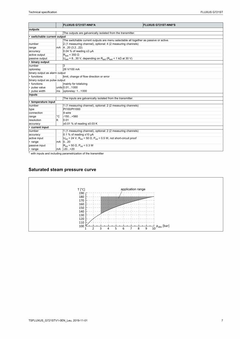
Saturated steam pressure curve
outputsThe outputs are galvanically isolated from the transmitter.
• switchable current outputThe switchable current outputs are menu selectable all together as passive or active.
number 2 (1 measuring channel), optional: 4 (2 measuring channels)range mA 4...20 (3.2...22)accuracy 0.04 % of reading ±3 μAactive output Rext < 350 Ωpassive output Uext = 8...30 V, depending on Rext (Rext < 1 kΩ at 30 V)• binary outputnumber 3optorelay 26 V/100 mAbinary output as alarm output• functions limit, change of flow direction or errorbinary output as pulse output• functions mainly for totalizing• pulse value units 0.01...1000• pulse width ms optorelay: 1...1000inputs
The inputs are galvanically isolated from the transmitter.• temperature inputnumber 1 (1 measuring channel), optional: 2 (2 measuring channels)type Pt100/Pt1000connection 4-wirerange °C -150...+560resolution K 0.01accuracy ±0.01 % of reading ±0.03 K• current inputnumber 1 (1 measuring channel), optional: 2 (2 measuring channels)accuracy 0.1 % of reading ±10 μAactive input Uint = 24 V, Rint = 50 Ω, Pint < 0.5 W, not short-circuit proof• range mA 0...20passive input Rint = 50 Ω, Pint < 0.3 W• range mA -20...+20
FLUXUS G721ST-NN0*A FLUXUS G721ST-NN0*S
1 with inputs and including parametrization of the transmitter
100110120130140150160170180190
1 32 54 76 98 10
T [°C]
pabs [bar]
application range

FLUXUS G721ST Technical specification
2019-11-01, TSFLUXUS_G721STV1-0EN_Leu8
Dimensions
*721**-****A
*721**-****S
94
320
thread: 6x M20 x 1.5 cable gland: max. 6x M20
25
5
165
.6
190.2
wall mount
9 x
5ø
6.2
9 x 5
in mm
255
240
cable gland: max. 6x M20 with flat gasket and counter nut
280
87
fixing holes for wall mounting
320
in mm
Technical specification FLUXUS G721ST
9TSFLUXUS_G721STV1-0EN_Leu, 2019-11-01
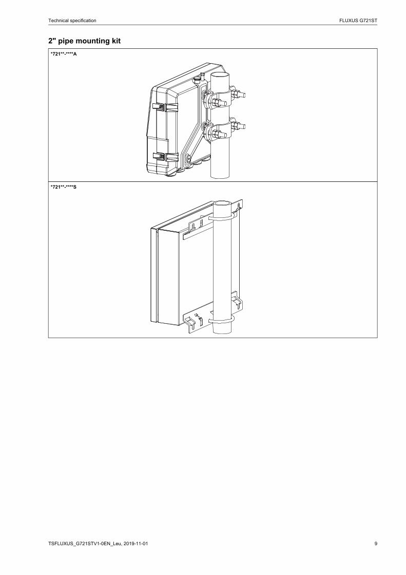
2" pipe mounting kit
*721**-****A
*721**-****S
FLUXUS G721ST Technical specification
2019-11-01, TSFLUXUS_G721STV1-0EN_Leu10
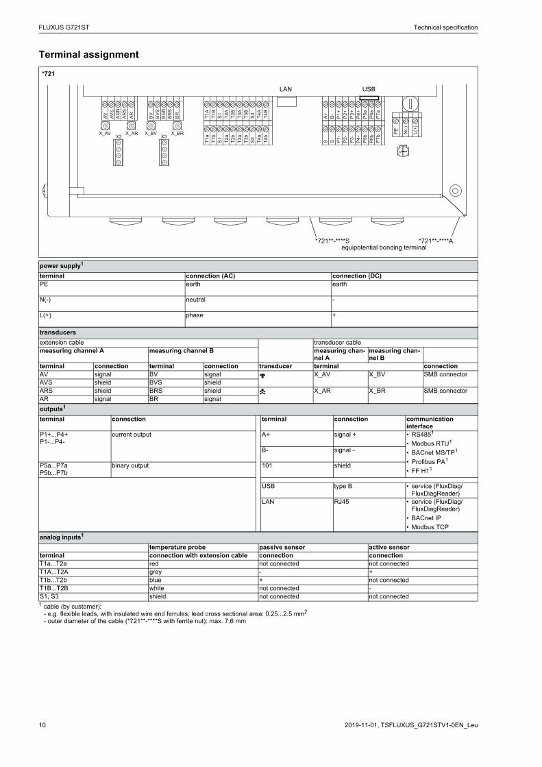
Terminal assignment
*721
power supply1
terminal connection (AC) connection (DC)PE earth earth
N(-) neutral -
L(+) phase +
transducers
extension cable transducer cablemeasuring channel A measuring channel B measuring chan-
nel Ameasuring chan-nel B
terminal connection terminal connection transducer terminal connectionAV signal BV signal X_AV X_BV SMB connectorAVS shield BVS shieldARS shield BRS shield X_AR X_BR SMB connectorAR signal BR signal
outputs1
terminal connection terminal connection communication interface
P1+...P4+P1-...P4-
current output A+ signal + • RS4851
• Modbus RTU1
• BACnet MS/TP1
• Profibus PA1
• FF H11
B- signal -
P5a...P7aP5b...P7b
binary output 101 shield
USB type B • service (FluxDiag/FluxDiagReader)
LAN RJ45 • service (FluxDiag/FluxDiagReader)
• BACnet IP
• Modbus TCP
analog inputs1
temperature probe passive sensor active sensorterminal connection with extension cable connection connectionT1a...T2a red not connected not connectedT1A...T2A grey - +T1b...T2b blue + not connectedT1B...T2B white not connected -S1, S3 shield not connected not connected1 сable (by customer):
- e.g. flexible leads, with insulated wire end ferrules, lead cross sectional area: 0.25...2.5 mm2
- outer diameter of the cable (*721**-****S with ferrite nut): max. 7.6 mm
A+B-P1+P2+P3+P4+P5aP6aP7a
S S P1-P2-P3-P4-P5bP6bP7bX2 X3
X_AV X_AR X_BV X_BR
T1A
T1B
S1T2A
T2B
T3A
T3B
S3
T4B
T4A
T1a
T1b
S1T2a
T2b
T3a
T3b
S3
T4b
T4a
N(-)
PE L(+)
AV AVS
AGN
ARS
AR
BVBVS
BGN
BRS
BR
LAN USB
*721**-****S *721**-****Aequipotential bonding terminal
Technical specification FLUXUS G721ST
11TSFLUXUS_G721STV1-0EN_Leu, 2019-11-01
Transducers
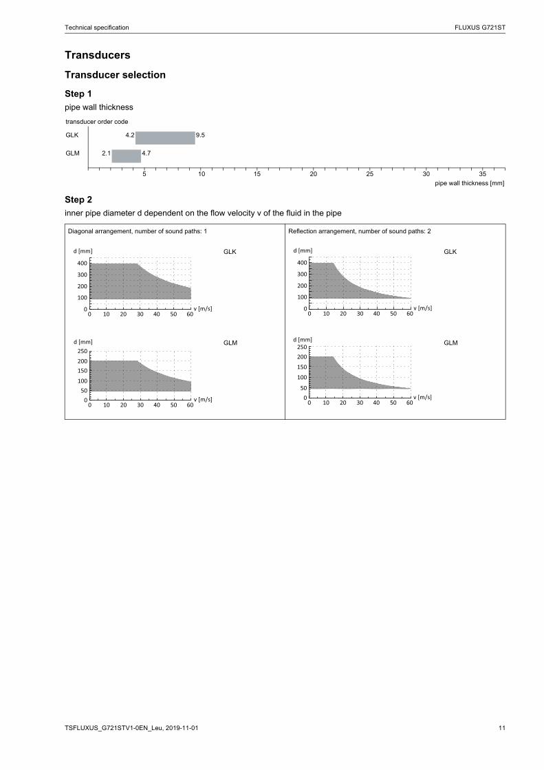
Transducer selection
Step 1
pipe wall thickness
Step 2
inner pipe diameter d dependent on the flow velocity v of the fluid in the pipe
transducer order code
GLK 4.2 9.5
GLM 2.1 4.7
5 10 15 20 25 30 35
pipe wall thickness [mm]
Diagonal arrangement, number of sound paths: 1 Reflection arrangement, number of sound paths: 2
GLK GLK
GLM GLM
00 10 20 30 40 50 60
100
200
300
400
d [mm]
v [m/s] 00 10 20 30 40 50 60
100
200
300
400
d [mm]
v [m/s]
00 10 20 30 40 50 60
50100
150200250
d [mm]
v [m/s] 00 10 20 30 40 50 60
50
100
150
200250
d [mm]
v [m/s]

FLUXUS G721ST Technical specification
2019-11-01, TSFLUXUS_G721STV1-0EN_Leu12
Technical data
order code GLK-SNNTS/** GLM-SNNTS/**technical type G(RT)K1S52 G(RT)M1S52transducer frequency MHz 0.5 1inner pipe diameter dmin. mm 90 45max. mm 400 200pipe wall thicknessmin. mm 4.2 2.1max. mm 9.5 4.7materialhousing PPSU with
stainless steel cap 316Ti (1.4571)
PPSU with stainless steel cap 316Ti (1.4571)
contact surface PPSU PPSUdegree of protection IP65 IP65transducer cabletype 1699 1699length m 5 4length (***-*****/LC) m 9 9dimensionslength l mm 128.5 74width b mm 51 32height h mm 67.5 40.5dimensional drawing
weight (without cable)
kg 0.8 0.16
storing temperaturemin. °C -40 -40max. °C +180 +180operating temperature1
min. °C 100 100max. °C 180 180warm-up time h 3 1temperature com-pensation
x x
1 completely thermically insulated transducer installation necessary
l
hb
l
hb
Technical specification FLUXUS G721ST
13TSFLUXUS_G721STV1-0EN_Leu, 2019-11-01
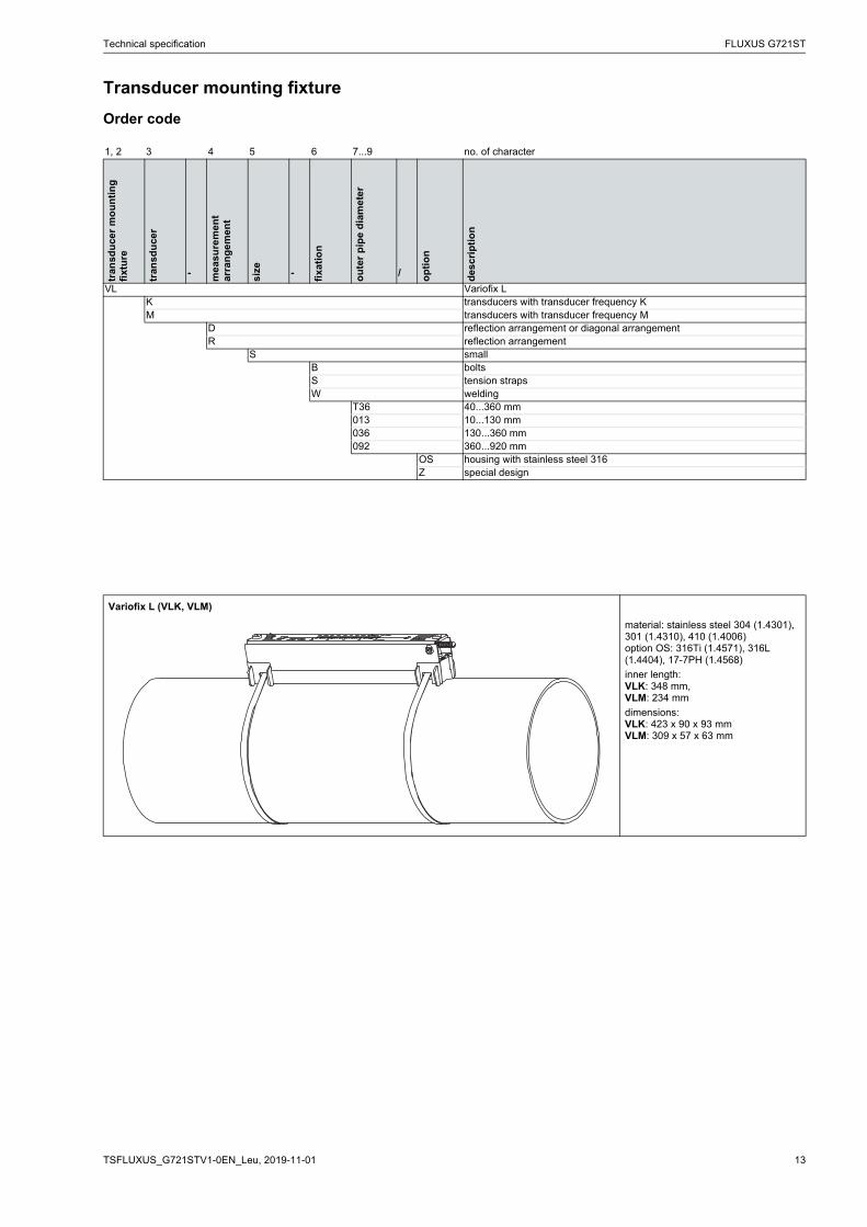
Transducer mounting fixture
Order code
1, 2 3 4 5 6 7...9 no. of character
tran
sdu
cer
mo
un
tin
g
fixt
ure
tran
sdu
cer
- me
asu
rem
en
t ar
ran
gem
ent
size - fixa
tio
n
ou
ter
pip
e d
iam
ete
r
/ op
tio
n
des
crip
tio
n
VL Variofix LK transducers with transducer frequency KM transducers with transducer frequency M
D reflection arrangement or diagonal arrangementR reflection arrangement
S smallB boltsS tension strapsW welding
T36 40...360 mm013 10...130 mm036 130...360 mm092 360...920 mm
OS housing with stainless steel 316Z special design
Variofix L (VLK, VLM)
material: stainless steel 304 (1.4301), 301 (1.4310), 410 (1.4006)option OS: 316Ti (1.4571), 316L (1.4404), 17-7PH (1.4568)
inner length:VLK: 348 mm,VLM: 234 mm
dimensions:VLK: 423 x 90 x 93 mmVLM: 309 x 57 x 63 mm

FLUXUS G721ST Technical specification
2019-11-01, TSFLUXUS_G721STV1-0EN_Leu14
Coupling materials for transducers
type ambient temperature
°Ccoupling foil type VT1 -10...+200coupling compound type E2 -30...+2001 fluid temperature 200 °C: min. 2 years2 in combination with type VT only

Technical specification FLUXUS G721ST
15TSFLUXUS_G721STV1-0EN_Leu, 2019-11-01
Damping coatThe damping coat will be used to reduce acoustic noise influences on the measurement.
Technical data
Example (diagonal arrangement)
order code ACC-PE-GNNN-/DPL1material multipolymeric matrix/inorganic ceramic coatingproperties heat resistant, inertfluid temperature when applying
°C 10...200
drying time (example)
approx. 3 h at 20 °Capprox. 15 min at 150 °C
temperature resis-tance in dry state
°C max. 650
packing drum l 1durability of the packing drum (unopened)
2 years
Observe installation instructions (TI_DampingCoat).
damping coat
transducer
FLUXUS G721ST Technical specification
2019-11-01, TSFLUXUS_G721STV1-0EN_Leu16
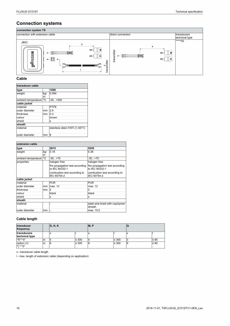
Connection systems
Cable
Cable length
connection system TS
connection with extension cable direct connection transducerstechnical type*****52
transducer cable
type 1699weight kg/
m0.094
ambient temperature °C -55...+200cable jacketmaterial PTFEouter diameter mm 2.9thickness mm 0.3colour brownshield xsheathmaterial stainless steel 316Ti (1.4571)
outer diameter mm 8
extension cable
type 2615 5245weight kg/
m0.18 0.38
ambient temperature °C -30...+70 -30...+70properties halogen free
fire propagation test according to IEC 60332-1
combustion test according to IEC 60754-2
halogen free
fire propagation test according to IEC 60332-1
combustion test according to IEC 60754-2
cable jacketmaterial PUR PURouter diameter mm max. 12 max. 12thickness mm 2 2colour black blackshield x xsheathmaterial - steel wire braid with copolymer
sheathouter diameter mm - max. 15.5
transducer frequency
G, H, K M, P Q
transducerstechnical type
x l x l x l
*R***5* m 5 ≤ 300 4 ≤ 300 3 ≤ 90option LC:*L***5*
m 9 ≤ 300 9 ≤ 300 9 ≤ 90
x - transducer cable length
l - max. length of extension cable (depending on application)
tra
nsm
itte
r
JB03x
l
tran
smitt
er
x
Technical specification FLUXUS G721ST
17TSFLUXUS_G721STV1-0EN_Leu, 2019-11-01
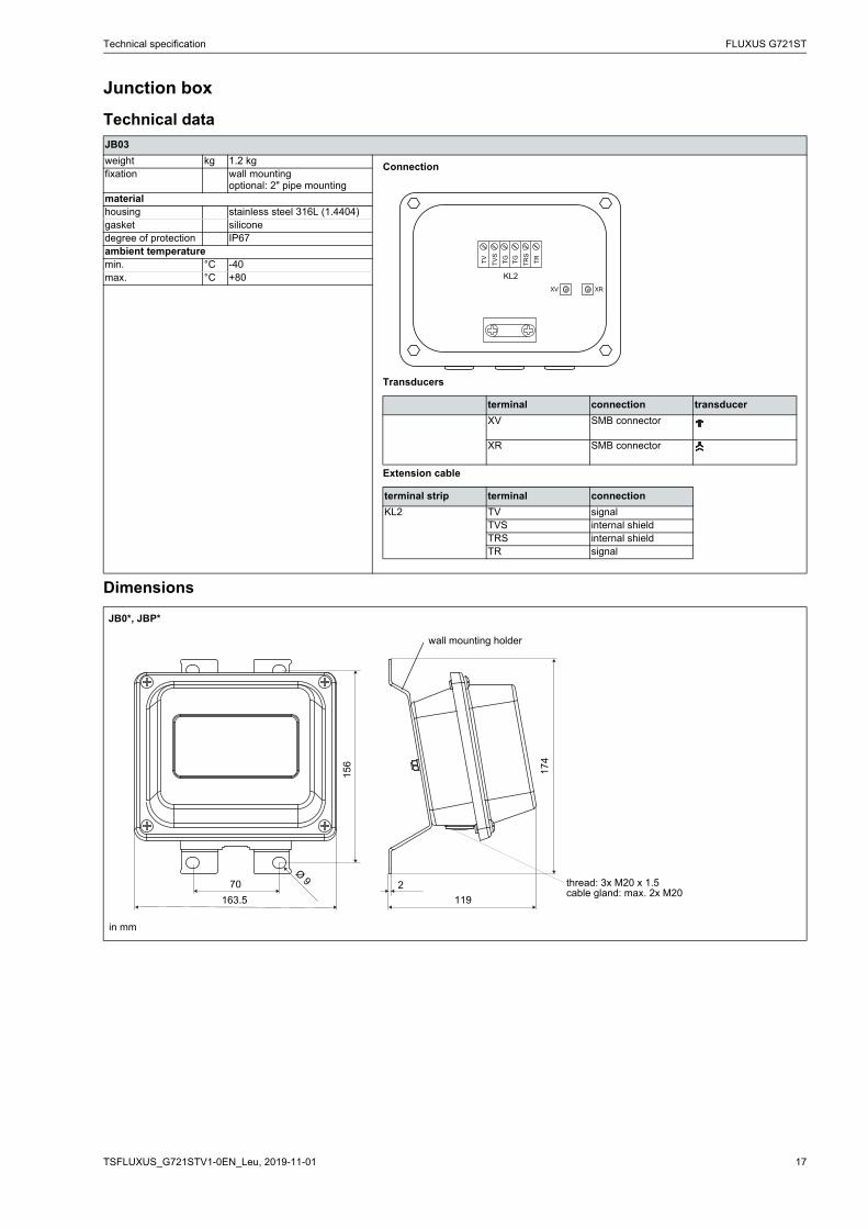
Junction box
Technical data
Dimensions
JB03
weight kg 1.2 kgfixation wall mounting
optional: 2" pipe mountingmaterialhousing stainless steel 316L (1.4404)gasket siliconedegree of protection IP67ambient temperaturemin. °C -40max. °C +80
JB0*, JBP*
Connection
Transducers
Extension cable
terminal connection transducer
XV SMB connector
XR SMB connector
terminal strip terminal connection
KL2 TV signalTVS internal shieldTRS internal shieldTR signal
174
119
2
wall mounting holder
70
163.5
15
6
Ø 9 thread: 3x M20 x 1.5cable gland: max. 2x M20
in mm

FLUXUS G721ST Technical specification
2019-11-01, TSFLUXUS_G721STV1-0EN_Leu18
2" pipe mounting kit
JB**

Technical specification FLUXUS G721ST
19TSFLUXUS_G721STV1-0EN_Leu, 2019-11-01
Clamp-on temperature probe (optional)
Technical data
Fixation
PT12N, PT12N-LC
order code PT12N:ACC-PE-GNNN-/T109ACC-PE-GNNN-/T106 (mat-ched)
PT12N-LC:ACC-PE-GNNN-/T113ACC-PE-GNNN-/T112 (mat-ched)
design clamp-onoption: with long cable
type Pt100connection 4-wiremeasuring range °C -30...+250accuracy T ±(0.15 °C + 2 . 10-3 . |T [°C]|)
class Aaccuracy ΔT(2x Pt matched according to EN 1434-1)
≤ 0.1 K (3 K < ΔT < 6 K), more corresponding to EN 1434-1
response time s 50housing aluminumdegree of protection IP66dimensions
length l mm 20width b mm 15height h mm 13dimensional drawing
weight kg 0.25accessories
thermal conductivity foil 250 °C
x
tension strap PT12N
material: stainless steel 301 (1.4310), 410 (1.4006)
thermal insulation necessary
Connection system
Connection
Cable
connection with extension cable direct connection
temperature probe
red
red/blue
white/blue
white
PT12N PT12N-LC extension cable
type 4 x 0.25 mm² black LIYCY 8 x 0.14 mm² greystandard length m 3 15 5/10/25max. length m - 200cable jacket PTFE PVC
extension cable
junction boxh
lb

FLUXUS G721ST Technical specification
2019-11-01, TSFLUXUS_G721STV1-0EN_Leu20
Junction box
Dimensions
JBT3
order code ACC-PE-GNNN-/JB6weight kg 1.2 kgfixation wall mounting
optional: 2" pipe mountingmaterialhousing stainless steel 316L (1.4404)gasket siliconedegree of protection IP67ambient temperaturemin. °C -40max. °C +80
JBTx
Connection
Temperature probe
Extension cable
terminal strip terminal connection
KL1 1 red2 red/blue3 white4 white/blue
terminal strip terminal connection
KL2 1 red2 grey3 white4 blue
174
119
2
wall mounting holder
70
163.5
15
6
Ø 9
thread: 3x M20 x 1.5cable gland: max. 2x M12
in mm

Technical specification FLUXUS G721ST
21TSFLUXUS_G721STV1-0EN_Leu, 2019-11-01
2" pipe mounting kit
JBxx

FLEXIM GmbHBoxberger Str. 4
12681 BerlinGermany
Tel.: +49 (30) 93 66 76 60Fax: +49 (30) 93 66 76 80
internet: www.flexim.come-mail: [email protected]
Subject to change without notification.Errors excepted.
FLUXUS is a registered trademark of FLEXIM GmbH.
Copyright (©) FLEXIM GmbH 2019
2019-11-01, TSFLUXUS_G721STV1-0EN_Leu