technical requirements for household shelters
TRANSCRIPT

HS-2012
TECHNICAL
REQUIREMENTS
FOR
HOUSEHOLD
SHELTERS
2012

--
CONTENTS
All rights reserved. No part of this publication may be reproduced, stored in a retrieval system, or transmitted in any form or by any means, electronic, mechanical, photocopying, recording or otherwise, without the prior permission of the SCDF and BCA.
August 2012

-I-
CONTENTS
CHAPTER 1: INTRODUCTION 1
1.1 GENERAL ............................................................................................................ 1
1.2 APPLICATION OF HS TECHNICAL REQUIREMENTS ....................................... 1
1.3 PEACETIME USE ................................................................................................ 1
1.4 ABBREVIATIONS ................................................................................................ 1
1.5 DEFINITIONS ....................................................................................................... 2
CHAPTER 2: ARCHITECTURAL REQUIREMENTS 3
2.1 HS OR NS FORM ................................................................................................. 3
2.2 SIZE OF HS .......................................................................................................... 3
2.2.1 Area and Volume 3
2.2.2 Height 3
2.3 WALL AND SLAB THICKNESS OF HS AND NS ................................................ 4
2.3.1 Wall Thickness of HS and NS 4
2.3.2 Slab Thickness of HS and Enclosed NS 4
2.3.3 Slab Thickness of HS and Non-Enclosed NS 5
2.4 LOCATION OF HS ............................................................................................... 5
2.4.1 HS Position 5
2.4.2 HS Tower 5
2.4.3 Setback Distances of HS Walls (Without Reinforced Concrete Down-hang Beams along EBL) 6
2.4.4 Setback Distances of HS Walls (With Reinforced Concrete Down-hang Beams along EBL) 6
2.4.5 Setback Distances of Basement HS 7
2.4.6 Setback Distance of HS located next to RC Lift Core or/ and Refuse Chute or/ and Riser 7
2.5 HS DOOR ............................................................................................................. 7
2.5.1 Dimensions 7
2.5.2 Door Frame 7
2.5.3 Strengthened Ceiling Slab Outside HS Door and HS Walls 8
2.6 FIXTURES IN HS ................................................................................................. 8
2.6.1 General 8
2.6.2 Power Points 9
2.6.3 Light Fittings 9
2.6.4 Cable Entries and Openings 9
2.7 NS IN HS TOWER ................................................................................................ 9
2.7.1 Aggregate Wall Heights of NS 9
2.7.2 Shielded and Unshielded NS Walls/Columns 9

-II-
2.8 TRANSFER STRUCTURE SUPPORTING HS TOWER ..................................... 10
2.8.1 General 10
2.8.2 Transfer Structure 10
2.9 HS BENEATH AN INTERNAL STAIRCASE ...................................................... 10
2.10 FINISHES IN HS ................................................................................................. 11
2.11 EXIT STAIRCASE .............................................................................................. 11
2.12 DOOR RECESS ON HS WALL .......................................................................... 11
LIST OF TABLES ............................................................................................... 12 to 116
LIST OF FIGURES ................................................................................................ 17 to 43
CHAPTER 3: STRUCTURAL REQUIREMENTS 44
3.1 GENERAL .......................................................................................................... 44
3.2 MATERIALS ....................................................................................................... 44
3.2.1 Concrete 44
3.2.2 Steel Reinforcement 44
3.3 ANALYSIS ......................................................................................................... 44
3.3.1 General 44
3.3.2 Beam Supported on HS wall 44
3.3.3 Shielded NS walls and/or NS columns 44
3.3.4 Unshielded NS Wall(s) and/or NS Columns 45
3.3.5 Transfer Structure Supporting HS Tower 46
3.3.5.1 Design Against Collapse Load 46
3.3.5.2 Shielded Transfer Structure 46
3.3.5.3 Unshielded Transfer Structure 46
3.4 MEMBER DIMENSIONS AND REINFORCEMENT REQUIREMENTS ............... 47
3.4.1 Member Dimensions 47
3.4.2 Reinforcement Requirements 47
3.4.2.1 Wall Reinforcements of HS and NS 47
3.4.2.2 Slab Reinforcements of HS and NS 48
3.4.2.3 Ceiling Slab Immediately Outside the HS 48
3.4.2.4 HS Slab Which Is Integrated With Pile-Cap/ Footing 48
3.5 DETAILING OF HS TOWER .............................................................................. 48
3.5.1 General 48
3.5.2 Lap and Anchorage Length 48
3.5.3 Concrete Cover 49
3.5.4 Cast-In-Situ and Precast Elements 49
3.5.5 Joints 50

-III-
3.6 PENETRATION OF SERVICES ......................................................................... 50
3.6.1 Electrical Services 50
3.6.2 Water and Gas Services 51
LIST OF TABLES ................................................................................................. 52 to 53
LIST OF FIGURES ................................................................................................ 54 to 85
CHAPTER 4: VENTILATION SLEEVES 86
4.1 GENERAL .......................................................................................................... 86
4.2 POSITION .......................................................................................................... 86
4.3 ACCESSIBILITY OF VENTILATION SLEEVES ................................................. 86
4.3.1 Clearance in front of and around Fragmentation Plate 86
4.3.2 False Ceiling below Ventilation Sleeves 86
4.4 FRAGMENTATION PLATE ................................................................................ 87
LIST OF FIGURES ................................................................................................ 88 to 91
CHAPTER 5: HS DOOR 92
5.1 GENERAL .......................................................................................................... 92
5.2 APPROVED HS DOOR ...................................................................................... 92
5.3 HS DOOR NOTICE............................................................................................. 92
5.4 SPECIFICATION OF HS DOOR NOTICE .......................................................... 92
LIST OF FIGURES ................................................................................................ 93 to 94
CHAPTER 6: CONSTRUCTION AND COMMISSIONING 95
6.1 GENERAL .......................................................................................................... 95
6.2 STRUCTURAL WORKS ..................................................................................... 95
6.3 HS DOOR ........................................................................................................... 96
6.4 PEACETIME REQUIREMENT OF VENTILATION SLEEVES ............................ 96
6.5 COMMISSIONING REQUIREMENTS................................................................. 96
CHAPTER 7: PERMITTED AND NOT PERMITTED WORKS TO HS TOWER 98
7.1 GENERAL .......................................................................................................... 98
7.2 PERMITTED AND NOT PERMITTED WORKS .................................................. 98
7.2.1 Permitted Works to HS 98
7.2.2 Not Permitted Works to HS 99
7.2.3 Not Permitted Works to NS 100

-IV-
LIST OF TABLES (CHAPTER 2) TABLE 2.2.1(b): MINIMUM INTERNAL HS FLOOR AREA AND VOLUME ........................... 12
TABLE 2.2.1(c): NUMBER OF SQUARE UNITS (0.6 m x 0.6 m) USED FOR THE ASSESSMENT OF TRAPEZOIDAL OR L-SHAPED HS ............................. 12
TABLE 2.3.1(a): MINIMUM HS WALL THICKNESS (FOR LANDED DEVELOPMENT) ....... 13
TABLE 2.3.1(b): MINIMUM HS AND NS WALL THICKNESS (FOR NON-LANDED DEVELOPMENT) ......................................................................................... 13
TABLE 2.4.3(a): MINIMUM SETBACK DISTANCES OF HS WALLS WITHOUT REINFORCED CONCRETE DOWN-HANG BEAM ALONG EBL ............... 14
TABLE 2.4.4(a): MINIMUM SETBACK DISTANCES OF HS WALLS WITH REINFORCED CONCRETE DOWN-HANG BEAM ALONG EBL ........................................ 15
TABLE 2.4.5(a): MINIMUM SETBACK DISTANCES OF BASEMENT HS WALLS (FACING REINFORCED CONCRETE BASEMENT STOREY WALLS WITH OPENING) ................................................................................................... 16
LIST OF FIGURES (CHAPTER 2)
FIGURE 2.2.1(a) EXAMPLES OF HS OF DIFFERENT SHAPES ........................................... 17
FIGURE 2.2.2(a) HS CLEAR HEIGHT IN NON-LANDED AND LANDED DEVELOPMENTS .... ..................................................................................................................... 18
FIGURE 2.2.2(b) SECTION OF HS TOWER SHOWING HS AND NS CLEAR HEIGHTS ..... 19
FIGURE 2.3.1(c) INTERNAL COMMON WALL BETWEEN TWO HS IN NON-LANDED AND LANDED CLUSTER HOUSING DEVELOPMENTS .................................... 20
FIGURE 2.3.1(d) SEPARATE WALLS BETWEEN TWO HS IN INTERMEDIATE LANDED DEVELOPMENTS ........................................................................................ 21
FIGURE 2.3.2 HS TOWER SHOWING HS AND NS (WITH ENCLOSED AND NON-ENCLOSED NS WALL) SLAB THICKNESS ............................................... 22
FIGURE 2.3.2(f) MINIMUM DIMENSIONS OF CEILING SLAB FOR HS IN LANDED DEVELOPMENT .......................................................................................... 23
FIGURE 2.4.1(b) HS WALL ABUTTING AN AIR WELL IN A LANDED DEVELOPMENT ...... 24
FIGURE 2.4.2(a) SCHEMATIC SECTION OF HS TOWER .................................................... 25
FIGURE 2.4.2(b) HS TOWER WITH TWO LARGER HS AT THE TOP .................................. 26
FIGURE 2.4.3a (i) REQUIREMENT ON SETBACK DISTANCE OF HS WALLS (WITHOUT DOWN-HANG BEAM) .................................................................................. 27
FIGURE 2.4.3a (ii) SETBACK DISTANCE OF HS WALLS (WITHOUT DOWN-HANG BEAM) .... ..................................................................................................................... 28
FIGURE 2.4.3(c) USAGE OF TRELLIS (RC/STEEL HOLLOW SECTIONS) TO MAKE UP FOR SHORTFALL IN SETBACK DISTANCE ............................................. 29
FIGURE 2.4.4(a) REQUIREMENT ON SETBACK DISTANCE OF HS WALLS (WITH DOWN-HANG BEAM) .............................................................................................. 30
FIGURE 2.4.4(b) DOWN-HANG BEAM LOCATED AWAY FROM EXTERNAL BUILDING INE ..................................................................................................................... 31
FIGURE 2.4.5(a) PLAN OF A BASEMENT HS ....................................................................... 32
FIGURE 2.4.5(b) PLAN OF A BASEMENT HS (WITH HS DOOR FACES RC BASEMENT STOREY WALL) .......................................................................................... 32
FIGURE 2.4.5(c) SECTIONAL VIEW OF A BASEMENT HS .................................................. 33
FIGURE 2.4.6(a) HS LOCATED NEXT TO LIFT SHAFT ........................................................ 34
FIGURE 2.4.6(b) HS LOCATED NEXT TO REFUSE CHUTE AND RISER ........................... 34

-V-
FIGURE 2.5.1(a) HS DOOR FRAME WITH SINGLE DOOR REBATE ................................... 35
FIGURE 2.5.1(b) HS DOOR FRAME WITH DOUBLE DOOR REBATES ............................... 35
FIGURE 2.5.2(a) CONCRETE WALL SEGMENT AT HS DOOR ............................................ 36
FIGURE 2.5.2(e) HS DOOR KERB ......................................................................................... 36
FIGURE 2.5.3 REQUIREMENTS FOR STRENGTHENED CEILING SLAB IN FRONT OF HS DOOR IN NON-LANDED DEVELOPMENT .......................................... 37
FIGURE 2.6.1(c) FIXTURES IN HS ......................................................................................... 38
FIGURE 2.7.1(a) HS TOWER .................................................................................................. 39
FIGURE 2.8.1(a) SHIELDING OF TRANSFER STRUCTURES SUPPORTING HS TOWER .... ..................................................................................................................... 40
FIGURE 2.8.1(b) SHIELDING OF TRANSFER SLAB/BEAMS/EXTERIOR COLUMNS/WALLS ..................................................................................................................... 41
FIGURE 2.9 HS BENEATH AN INTERNAL STAIRCASE ................................................ 42
FIGURE 2.12 DETAILS OF WALL RECESS FOR HS DOOR HANDLE ........................... 43 LIST OF TABLES (CHAPTER 3)
TABLE 3.3.4: LOAD COMBINATION AND VALUES OF PARTIAL SAFETY FACTORS (γf) FOR ULTIMATE LIMIT STATE (Unshielded NS Walls, Unshielded NS Columns or a Combination of Unshielded NS Walls and NS Columns) ...... 52
TABLE 3.3.5.1: LOAD COMBINATION AND VALUES OF PARTIAL SAFETY FACTORS (γf) FOR ULTIMATE LIMIT STATE (Design against Collapse Load and Unshielded/Shielded Transfer Structure) ..................................................... 52
TABLE 3.3.5.3: LOAD COMBINATION AND VALUES OF PARTIAL SAFETY FACTORS (γf) FOR ULTIMATE LIMIT STATE (Unshielded Transfer Structure) ................ 52
TABLE 3.4.2.1(a): MINIMUM REINFORCEMENT OF HS WALLS FOR LANDED DEVELOPMENTS ........................................................................................ 53
TABLE 3.4.2.1(b): MINIMUM REINFORCEMENT OF HS OR NS WALLS FOR NON-LANDED DEVELOPMENTS ........................................................................................ 53
LIST OF FIGURES (CHAPTER 3)
FIGURE 3.3.3 SHIELDED NS WALLS AND/OR NS COLUMNS ........................................ 54
FIGURE 3.3.4(a) UNSHIELDED NS WALL(S) ........................................................................ 55
FIGURE 3.3.4(b) UNSHIELDED NS COLUMN(S) .................................................................. 55
FIGURE 3.3.4(c) COMBINATION OF UNSHIELDED NS WALL(S) AND/OR NS COLUMN(S) . ..................................................................................................................... 55
FIGURE 3.3.5.2(a) SHIELDED TRANSFER SYSTEM THAT SUPPORTS HS TOWER ........... 56
FIGURE 3.3.5.3 UNSHIELDED TRANSFER SYSTEM THAT SUPPORTS HS TOWER...... 57
FIGURE 3.3.5.3a (i) UNSHIELDED TRANSFER BEAMS ............................................................ 58
FIGURE 3.3.5.3a (ii) UNSHIELDED TRANSFER SLAB ............................................................... 58
FIGURE 3.3.5.3b (i) UNSHIELDED TRANSFER WALLS ............................................................ 59
FIGURE 3.3.5.3b (ii) UNSHIELDED TRANSFER COLUMNS ...................................................... 59
FIGURE 3.5.4(a) PLAN OF HS ................................................................................................ 60
FIGURE 3.5.4(b) SECTIONAL DETAILS OF HS SLABS/WALLS ........................................... 61
FIGURE 3.5.4(c) SECTIONAL DETAILS OF HS SLABS/WALLS ........................................... 62
FIGURE 3.5.4(d) PLAN OF TWO HS WITH AN INTERNAL COMMON WALL ...................... 63

-VI-
FIGURE 3.5.4(e) SECTIONAL DETAILS OF TWO HS WITH AN INTERNAL COMMON WALL ..................................................................................................................... 64
FIGURE 3.5.4(f) DETAILS OF HS WALL REINFORCEMENT BAR NEAR HS DOOR ......... 65
FIGURE 3.5.4(g) TYPICAL DETAILS OF EMBEDDED CONDUIT IN HS WALL ................... 66
FIGURE 3.5.4(h) TYPICAL DETAILS OF TRIMMER BARS FOR VENTILATION SLEEVE ... 67
FIGURE 3.5.4(i) TYPICAL DETAILS OF TRIMMER BARS FOR WALL RECESS ................ 67
FIGURE 3.5.4(j) DETAILS OF SHEAR LINKS IN HS SLABS/WALLS .................................. 68
FIGURE 3.5.4(k) PLAN OF HS WITH PRE-CAST HS DOOR FRAME PANEL (TYPE 1) ...... 69
FIGURE 3.5.4(l) DETAILS AND SECTIONS OF PRE-CAST HS DOOR FRAME PANEL WITH VENTILATION SLEEVE ABOVE IT (TYPE 1) ................................... 70
FIGURE 3.5.4(m) SECTIONS OF PRE-CAST HS DOOR FRAME PANEL WITH VENTILATION SLEEVE ABOVE IT (TYPE 1) ............................................. 71
FIGURE 3.5.4(n) DETAILS AND SECTIONS OF PRE-CAST HS DOOR FRAME PANEL WITH VENTILATION SLEEVE ALONG ITS SIDE (TYPE 1) ...................... 72
FIGURE 3.5.4(o) SECTIONS OF PRE-CAST HS DOOR FRAME PANEL WITH VENTILATION SLEEVE ALONG ITS SIDE (TYPE 1) ................................. 73
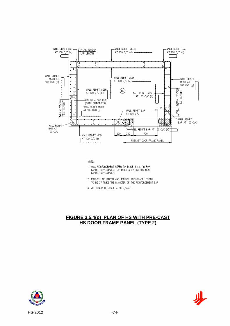
FIGURE 3.5.4(p) PLAN OF HS WITH PRE-CAST HS DOOR FRAME PANEL (TYPE 2) ...... 74
FIGURE 3.5.4(q) DETAILS AND SECTIONS OF PRE-CAST HS DOOR FRAME PANEL WITH VENTILATION SLEEVE ABOVE IT (TYPE 2) ................................... 75
FIGURE 3.5.4(r) SECTIONS OF PRE-CAST HS DOOR FRAME PANEL WITH VENTILATION SLEEVE ABOVE IT (TYPE 2) ............................................. 76
FIGURE 3.5.4(s) DETAILS AND SECTIONS OF PRE-CAST HS DOOR FRAME PANEL WITH VENTILATION SLEEVE ALONG ITS SIDE (TYPE 2) ...................... 77
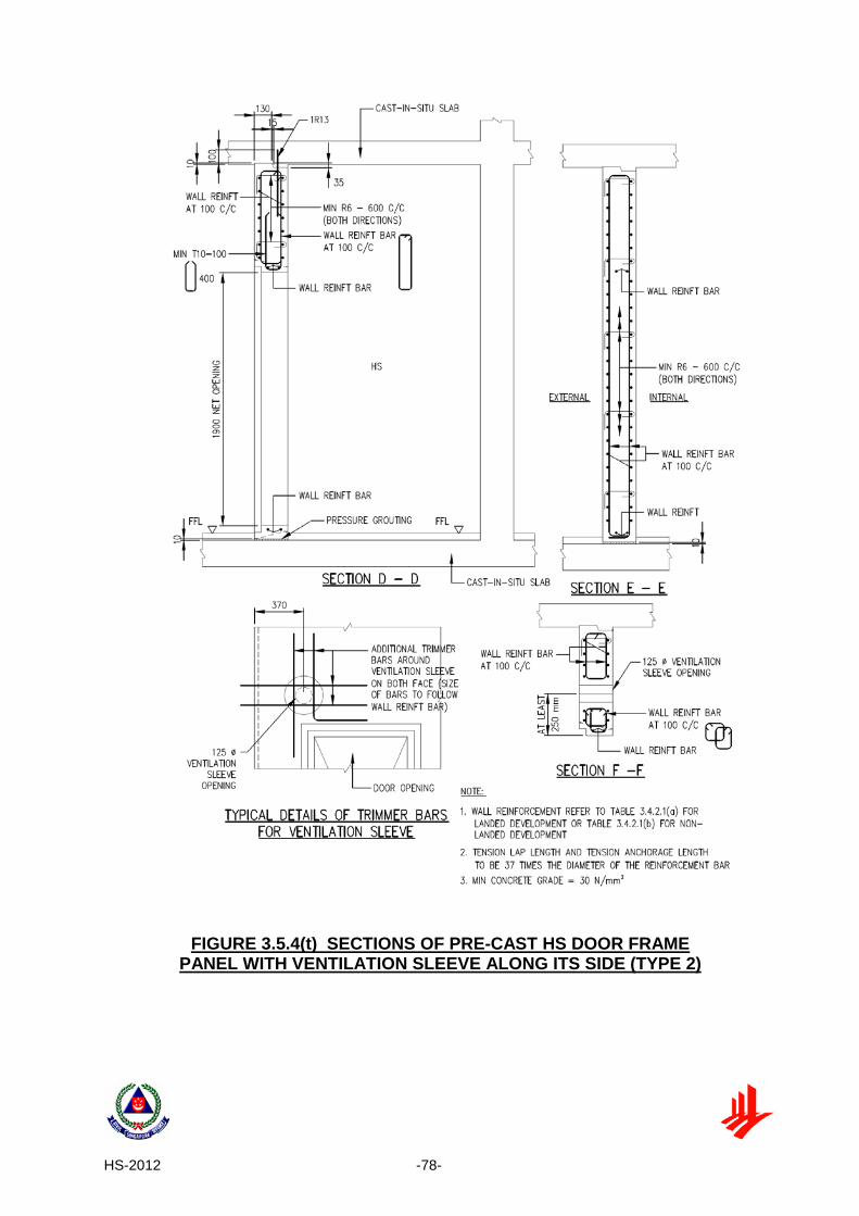
FIGURE 3.5.4(t) SECTIONS OF PRE-CAST HS DOOR FRAME PANEL WITH VENTILATION SLEEVE ALONG ITS SIDE (TYPE 2) ................................. 78
FIGURE 3.5.4(u) PLAN OF HS WITH PRE-CAST DOOR FRAME PANEL (TYPE 3) ............ 79
FIGURE 3.5.4(v) DETAILS OF PRE-CAST HS DOOR FRAME PANEL (TYPE 3) ................ 80
FIGURE 3.5.4(w) SECTIONS OF PRE-CAST HS DOOR FRAME PANEL (TYPE 3) ............. 81
FIGURE 3.5.4(x) SECTIONS OF PRE-CAST HS DOOR FRAME PANEL (TYPE 3) ............. 82
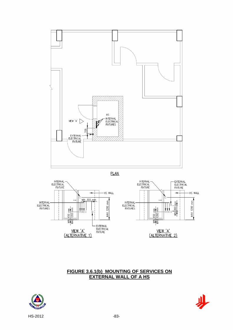
FIGURE 3.6.1(b) MOUNTING OF SERVICES ON EXTERNAL WALL OF A HS ................... 83
FIGURE 3.6.1(d) TYPICAL DETAILS OF EMBEDDED SOCKET/SWITCH ........................... 84
FIGURE 3.6.2(a) ENCASEMENT DETAILS OF WATER/GAS SERVICE PIPES PENETRATING THROUGH HS WALLS ..................................................... 85
LIST OF FIGURES (CHAPTER 4)
FIGURE 4.2(a) POSITION OF VENTILATION SLEEVES .................................................... 88
FIGURE 4.2(b) SECTIONAL VIEWS OF VENTILATION SLEEVES .................................... 89
FIGURE 4.3.1 MINIMUM CLEARANCE FOR FRAGMENTATION PLATE ........................ 90
FIGURE 4.3.2 PERFORATED ACCESS PANEL BELOW VENTILATION SLEEVE .......... 90
FIGURE 4.4 DETAILS OF VENTILATION SLEEVE AND FRAGMENTATION PLATE ... 91 LIST OF FIGURES (CHAPTER 5)
FIGURE 5.3(a) LOCATION OF NOTICE ON HS DOOR ...................................................... 93
FIGURE 5.3(b) SAMPLE HS DOOR NOTICE ...................................................................... 94

HS-2012 -1-
CHAPTER 1: INTRODUCTION 1.1 GENERAL
A household shelter (HS) is designed and constructed for the protection of people against weapon effects during a war emergency. It should not be used for protection during other emergency situations such as a fire in a building. For the convenience of the occupants, HS is located inside the individual house or flat.
HS shall be incorporated as part of the house or flat. This can be achieved by efficient space planning as well as optimal integration of the HS location with other spaces in a house or flat.
1.2 APPLICATION OF HS TECHNICAL REQUIREMENTS
The Technical Requirements for HS are applicable to all houses or flats, which are intended as complete and separate units for purpose of private dwelling.
1.3 PEACETIME USE
Every HS shall be designed to a specific peacetime use. The other statutory requirements governing the design and use of the HS space shall also be complied with.
1.4 ABBREVIATIONS
Clause Description Abbreviation
1.1 Household Shelter* HS
2.1 Non-Shelter NS
2.4.1 (b) External Building Line EBL
2.5.2 (e) Finished Floor Level FFL
Table 2.2.1 (b) Gross Floor Area GFA
*Under the Civil Defence Shelter Act (CDSA), a household shelter would be required in a “new building” which means a building that is constructed on a vacant land or in place of building which has been or would be demolished
HS-2012 -2-
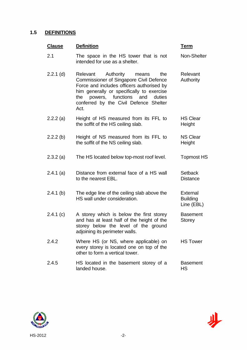
1.5 DEFINITIONS
Clause Definition Term
2.1 The space in the HS tower that is not intended for use as a shelter.
Non-Shelter
2.2.1 (d) Relevant Authority means the Commissioner of Singapore Civil Defence Force and includes officers authorised by him generally or specifically to exercise the powers, functions and duties conferred by the Civil Defence Shelter Act.
Relevant Authority
2.2.2 (a) Height of HS measured from its FFL to the soffit of the HS ceiling slab.
HS Clear Height
2.2.2 (b) Height of NS measured from its FFL to the soffit of the NS ceiling slab.
NS Clear Height
2.3.2 (a) The HS located below top-most roof level. Topmost HS
2.4.1 (a) Distance from external face of a HS wall to the nearest EBL.
Setback Distance
2.4.1 (b) The edge line of the ceiling slab above the HS wall under consideration.
External Building Line (EBL)
2.4.1 (c) A storey which is below the first storey and has at least half of the height of the storey below the level of the ground adjoining its perimeter walls.
Basement Storey
2.4.2 Where HS (or NS, where applicable) on every storey is located one on top of the other to form a vertical tower.
HS Tower
2.4.5 HS located in the basement storey of a landed house.
Basement HS

HS-2012 -3-
CHAPTER 2: ARCHITECTURAL REQUIREMENTS 2.1 HS OR NS FORM
The configuration of a HS or NS on plan shall be rectangular, square, trapezoidal or L-shaped.
2.2 SIZE OF HS
2.2.1 Area and Volume (a) The maximum internal length of any floor and roof slab of a HS shall be
4000 mm. The minimum internal width of a HS shall be 1200 mm. The internal length and width of HS walls shall be designed with an increment of 50mm. See FIGURE 2.2.1(a).
(b) If the configuration of HS on plan is rectangular or square, the minimum internal floor area and minimum internal volume of a HS shall be in accordance with TABLE 2.2.1(b).
(c) If the configuration of HS on plan is trapezoidal or L-shaped, the minimum
internal floor area, minimum internal volume of a HS and the number of 0.6 m x 0.6 m square units shall be as specified in TABLE 2.2.1(c) and as illustrated in FIGURE 2.2.1(a).
(d) The maximum internal floor area of a HS shall be 4.8 m2. Internal floor area
exceeding 4.8 m2 may be allowed subject to the approval from the relevant authority.
2.2.2 Height
(a) The minimum and maximum HS clear height shall be 2400 mm and 3900
mm respectively. See FIGURE 2.2.2(a).
(b) The maximum NS clear height shall be 3900 mm. Where NS clear height is more than 3900 mm, intermediate RC slab or RC beams shall be provided. The RC beams shall be designed with at least equivalent stiffness to RC slab. If the NS is designed with 2 walls, RC beams shall be provided at the peripheral of NS. See FIGURE 2.2.2(b).

HS-2012 -4-
2.3 WALL AND SLAB THICKNESS OF HS AND NS
2.3.1 Wall Thickness of HS and NS
(a) The minimum HS and NS wall thickness shall be in accordance with TABLE 2.3.1(a) and TABLE 2.3.1(b).
(b) Wall thickness of any HS or NS within the HS tower shall not be less than the wall thickness of the HS or NS above it.
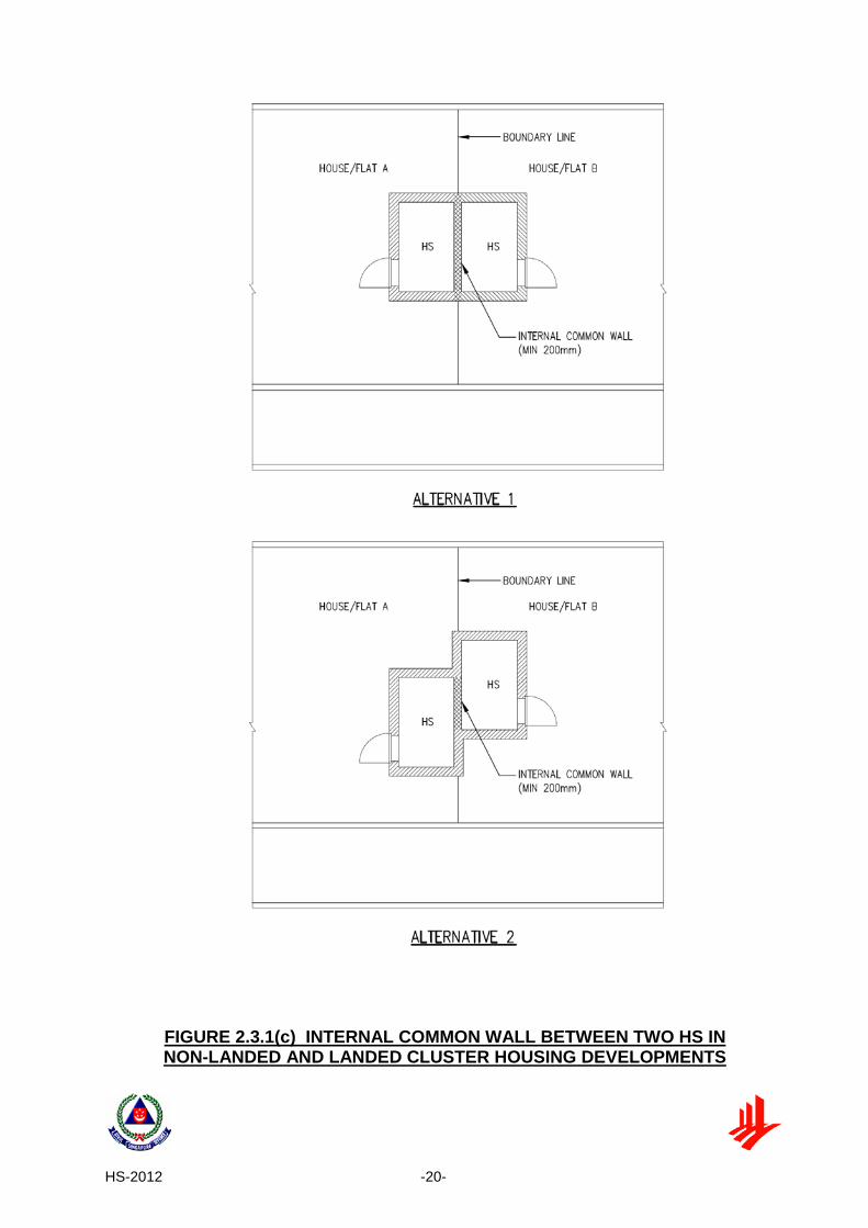
(c) Internal common wall between two adjacent HS - 200 mm for non-landed
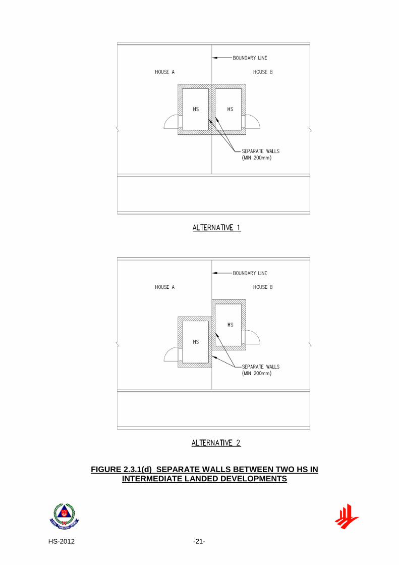
and landed cluster housing developments. See FIGURE 2.3.1(c). (d) For landed developments where the two HS are abutting each other, the
common wall shall be cast as two separate adjoining walls. See FIGURE 2.3.1(d).
(e) The minimum thickness of the basement HS wall which is in direct contact
with earth throughout its entire height shall be 250 mm thick. See FIGURE 2.4.5(a) and FIGURE 2.4.5(b).
(f) The minimum thickness of the basement HS wall facing a reinforced
concrete basement storey wall without any opening within the influence zone shall be 200 mm. See FIGURE 2.4.5(a) and FIGURE 2.4.5(b).
(g) The minimum thickness of the basement HS wall facing a reinforced
concrete basement storey wall with opening within the influence zone shall be in accordance with TABLE 2.3.1(a).
2.3.2 Slab Thickness of HS and Enclosed NS
(a) Ceiling slab of top-most HS in non-landed development - 300 mm. See
FIGURE 2.3.2.
(b) Slab between 2 HS - 175 mm. See FIGURE 2.3.2. (c) Floor slab of bottom-most HS or NS in contact with soil – 200 mm. See
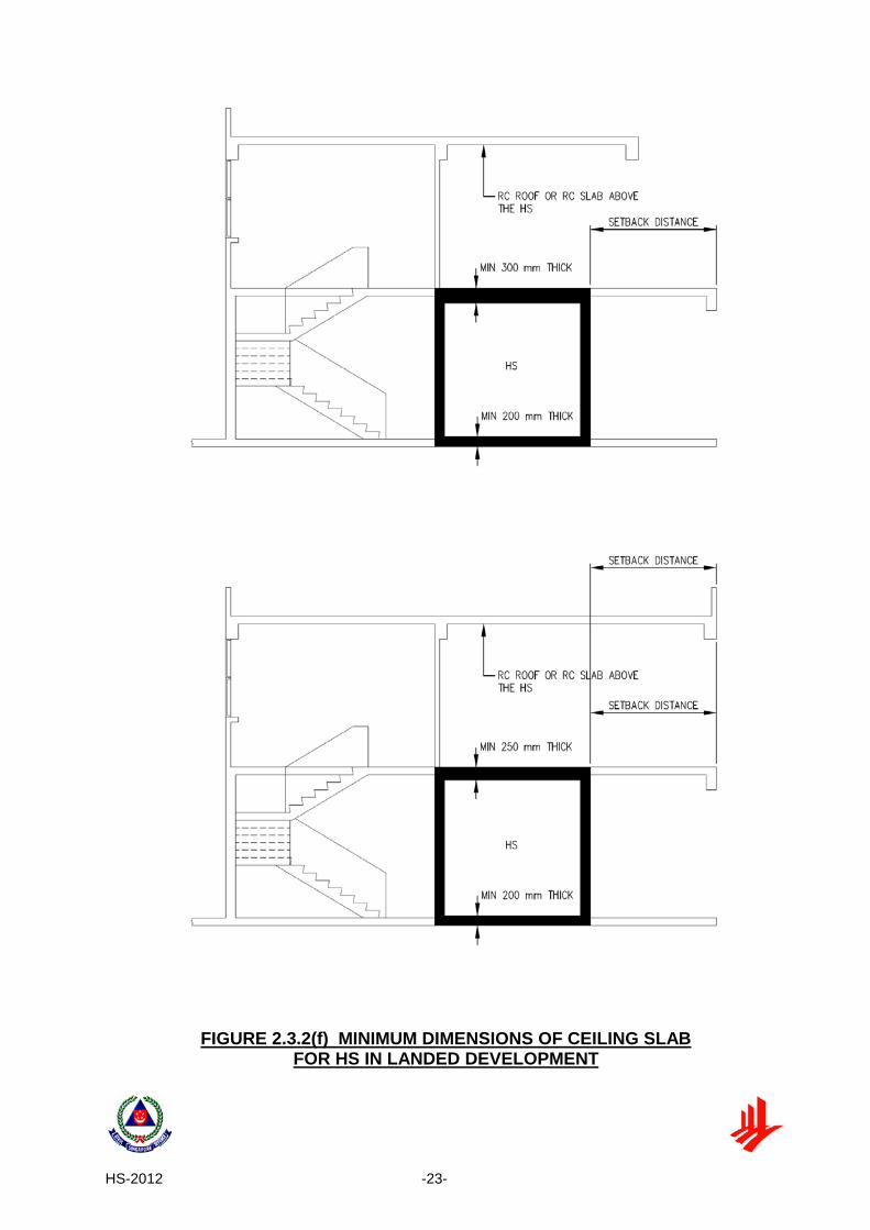
FIGURE 2.3.2. (d) Slab between 2 enclosed NS – 175 mm. See FIGURE 2.3.2. (e) Slab between HS and enclosed NS – 175 mm. See FIGURE 2.3.2. (f) Ceiling slab of top-most HS in landed development – 300 mm or 250 mm (if
there is a RC roof or another RC slab above the HS that is equal or extend beyond the required setback distance of that HS wall. See FIGURE 2.3.2(f).

HS-2012 -5-
2.3.3 Slab Thickness of HS and Non-Enclosed NS (a) Floor slab of HS that is directly supported by non-enclosed NS or NS wall
or column – 300 mm. See FIGURE 2.3.2. (b) Ceiling slab of HS which is below non-enclosed NS, NS walls or columns
– 300mm. See FIGURE 2.3.2. (c) Slab between 2 non-enclosed NS – 175 mm. See FIGURE 2.3.2.
2.4 LOCATION OF HS
2.4.1 HS Position
(a) A HS has to be positioned such that the setback distance of each HS wall shall be as large as practical, and shall not be less than the minimum specified setback distance.
(b) A HS with minimum 300mm thick ceiling slab in a landed house may have
one of its walls (in which the HS door is not located) abutting or near to an air well. The air well, has to be located such that it abuts a party wall and/ or is surrounded by reinforced concrete slab at ceiling slab level of the HS or any reinforced concrete slab above ceiling slab of HS. The air well edge line shall not be regarded as EBL for the purpose of determining the minimum setback distance. The area of the air-well shall not be larger than 4.2m2 and the longer side of the air-well shall not be larger than 2.8m. See FIGURE 2.4.1(b).
(c) A HS can also be located in the basement storey of a landed house. Where
the HS is located underground away from basement of landed house, an underground access route leading to HS must be provided with a reinforced concrete ceiling slab of minimum thickness of 125 mm.
2.4.2 HS Tower
(a) In a building of more than one-storey, the HS (or NS, if any) on every storey
shall be located one on top of the other to form a vertical tower with its walls (where applicable) continuing to the foundation. See FIGURE 2.4.2(a).
(b) Up to 2 larger HS below main roof level are allowed to be located at the top
of the HS tower. Only one wall of the larger HS is allowed to be projected beyond the HS walls below it. The minimum thickness of the projected slab shall follow the wall thickness of the larger HS. See FIGURE 2.4.2(b).
(c) The space within a NS is not intended for protection of occupants during a
war emergency.

HS-2012 -6-
2.4.3 Setback Distances of HS Walls (Without Reinforced Concrete Down-hang Beams along EBL)
(a) The HS walls shall be located at minimum setback distances from the EBL
(See FIGURE 2.4.3a(i) and FIGURE 2.4.3a(ii)). The setback distances of the HS wall with HS door and the remaining 3 HS walls shall comply with TABLE 2.4.3(a).
(b) Where the storey height of a HS on the first storey is up to 3.6 m and is
greater than the storey heights of the HS directly above it, the minimum setback distances of the HS on the first storey shall be at least the same as the setback distances of the HS above it.
(c) For HS walls (where the HS door is not located), trellis constructed of RC or
steel hollow section may be used to make up for the shortfall in setback distance. However, a minimum 1000 mm RC ceiling slab from the HS wall shall be provided. A perpendicular or parallel trellis arrangement, or a combination of both, with respect to the HS wall concerned, shall comply with the geometrical configuration as shown in FIGURE 2.4.3(c).
2.4.4 Setback Distances of HS Walls (With Reinforced Concrete Down-hang Beams along EBL)
(a) Where a down-hang beam is provided along the EBL in front of HS walls, the minimum setback distance of that HS wall can be reduced based on the effective storey height and in accordance with TABLE 2.4.4(a). The effective storey height is determined by the storey height less the depth ‘d’ of the down-hang beam (See FIGURE 2.4.4 (a)). If a down-hang beam is also provided along the EBL in front of the HS wall with HS door, the setback distance of this wall shall be in accordance with TABLE 2.4.4(a).
(b) For HS walls (where the HS door is not located), trellis constructed of RC or steel hollow section may be used to make up for the shortfall in setback distance. However, a minimum 1000 mm RC ceiling slab from the HS wall shall be provided (FIGURE 2.4.4(b)). A perpendicular or parallel trellis arrangement, or a combination of both, with respect to the HS wall concerned, shall comply with the geometrical configuration as shown in FIGURE 2.4.3(c).
(c) Where the storey height of a HS on the first storey is up to 3.6 m and is greater than the storey heights of the HS directly above it, the minimum setback distances of the HS on the first storey shall be at least the same as the setback distances of the HS above it. Where a down-hang beam is provided at 2nd storey ceiling slab, the same down-hang beam shall be provided at 1st storey ceiling slab.
(d) Clause 2.4.4 shall apply only if the width of the reinforced concrete down-
hang beam is at least 125 mm.

HS-2012 -7-
2.4.5 Setback Distances of Basement HS
(a) For the HS in the basement, the minimum setback distances of the HS wall with HS door and the remaining 3 HS walls shall comply with the TABLE 2.4.5(a). (See FIGURE 2.4.5(a)).
(b) There is no setback distance requirement for basement HS wall with door if it faces a reinforced concrete basement storey wall not in direct contact with earth and the distance between them is at least 1500 mm (with no openings within the influence zone). (See FIGURE 2.4.5(b)).
(c) There is no setback distance requirement for basement HS wall (without HS
door) of landed house (See FIGURE 2.4.5(c)) if the HS wall is:
(i) in direct contact with earth throughout its full height and the earth extends out by a minimum distance of 1000 mm from the external face of the HS wall; or
(ii) facing a reinforced concrete basement storey wall in direct contact
with earth throughout its full height; or
(iii) facing a reinforced concrete basement storey wall not in direct contact with earth and the distance between them is at least 800 mm (with no openings within the influence zone).
2.4.6 Setback Distance of HS located next to RC Lift Core or/ and Refuse
Chute or/ and Riser RC lift core or/and refuse-chute or/ and riser can be located within the area of setback distances of HS walls. See FIGURE 2.4.6(a) and FIGURE 2.4.6(b).
2.5 HS DOOR
2.5.1 Dimensions
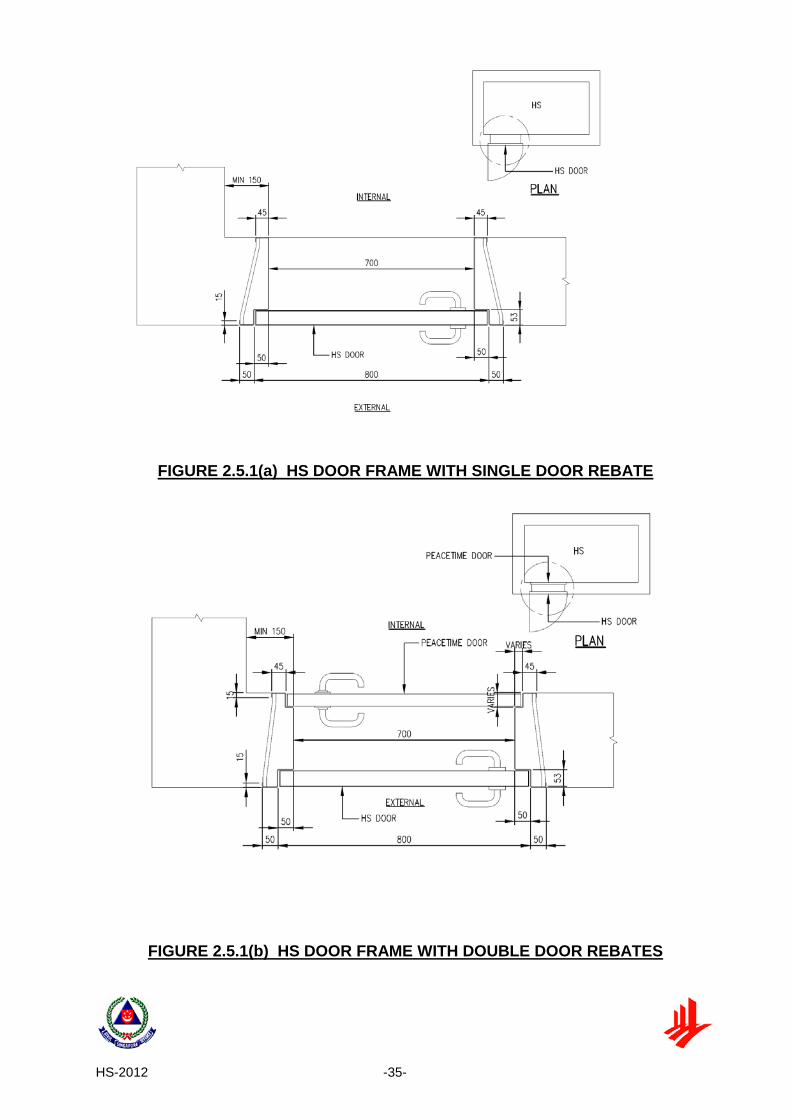
(a) The opening dimensions of HS door shall be 700mm (W) x 1900mm (H) See FIGURE 2.5.1(a).
(b) HS door frame that is cast together with the HS wall shall have single or
double door rebate. See FIGURE 2.5.1(a) and FIGURE 2.5.1(b).
2.5.2 Door Frame (a) There shall be a minimum 150mm reinforced concrete nib next to vertical
edge of the HS door frame. (See FIGURE 2.5.2(a)).

HS-2012 -8-
(b) For pre-cast door frame panel of Type 1, the reinforced concrete next to two vertical edges of the HS door frame shall be 300mm each. See FIGURE 3.5.4(k).
(c) For pre-cast door frame panel of Type 2, the reinforced concrete next to
vertical edges of the HS door frame shall be 300mm on one side, and 150mm plus the HS wall thickness on the other side. FIGURE 3.5.4(p).
(d) For pre-cast door frame panel of Type 3, the reinforced concrete panel with
full length or width of HS wall must be properly connected to the in-situ HS walls and slabs. See FIGURE 3.5.4(u).
(e) The door frame must be positioned such that its door is above FFL and can
be opened at least 90°. (See FIGURE 2.5.2 (e)).
2.5.3 Strengthened Ceiling Slab Outside HS Door and HS Walls
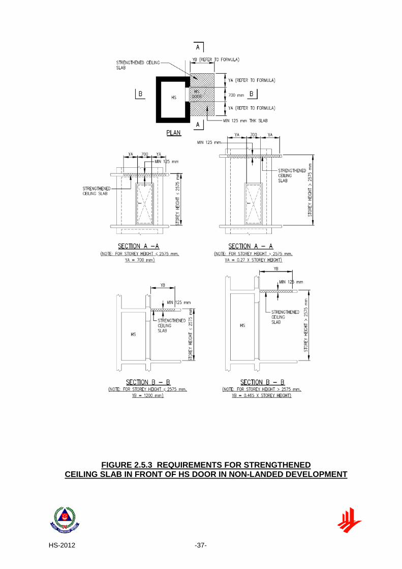
The minimum thickness of the reinforced concrete ceiling slab immediately outside the HS wall with HS door shall be 125 mm and structurally connected to HS tower (See FIGURE 2.5.3). This requirement shall only apply to HS in non-landed houses.
2.6 FIXTURES IN HS
2.6.1 General
(a) The following electrical and communication fixtures in steel or PVC conduit system shall be provided inside the HS to provide basic stay-in and communication facilities:
i) Switch and lighting points; ii) 13A switched socket outlets; iii) Telephone outlet; iv) TV and radio outlets.
(b) The electrical and communication fixtures shall be designed and installed in
accordance with the relevant local Codes of Practice and statutory requirements for peacetime usage.
(c) The mounting height of the lighting switch shall not exceed 1200 mm from
the FFL. The other electrical and communication fixtures shall be mounted at between 450 mm and 1200mm from the FFL to comply with the requirement as stipulated in the building codes. See FIGURE 2.6.1(c).

HS-2012 -9-
(d) Other fixtures, such as cabinets and shelves, which are required for peacetime use, are allowed provided they are easily dismantled and removed.
2.6.2 Power Points
One 13A switched socket outlet shall be provided in the vicinity of adjacent to the TV and radio outlets. An additional 13A switched socket outlet shall be provided for other electrical appliances such as fan.
2.6.3 Light Fittings
Light fittings shall be mounted on the soffit of HS ceiling slab using screws with non-metallic inserts. Wall-mounted light fittings are not permitted.
2.6.4 Cable Entries and Openings
All cable entry openings to the HS shall be fully and properly sealed to ensure air-tightness as required under Clause 3.6.
2.7 NS IN HS TOWER
2.7.1 Aggregate Wall Heights of NS
(a) Several NS can be stacked one on top of the other within an HS tower, without the need for NS floor slab to be connected to external floor slab, provided that the aggregate wall height of the NS does not exceed 12 m (See FIGURE 2.7.1(a)).
(b) Aggregate wall height of NS refers to the sum of the height(s) of NS
between two levels of the HS tower where the full external perimeters of the HS tower at those levels are structurally connected by floor slabs or tie beams to the structural frame of the building. The tie beams shall be designed with at least equivalent stiffness to the floor slab.
(c) The minimum thickness of the intermediate slabs between 2 NS shall be
175 mm.
2.7.2 Shielded and Unshielded NS Walls/Columns The relevant architectural technical requirements of the shielded and unshielded NS Columns/ Walls as stipulated in Chapter 3 Clause 3.3 shall be complied with.

HS-2012 -10-
2.8 TRANSFER STRUCTURE SUPPORTING HS TOWER 2.8.1 General
If the loads from walls of HS towers cannot be carried directly to the foundation, transfer structure can be used to carry the loads indirectly to the foundation. The transfer structure could take the form of slab, beams, or combination of both. When transfer structure is provided to carry HS tower, additional technical requirements described herein shall be complied with. Please note the following conditions in the HS tower design supported by transfer structure: a) RC slab shall be used as the shielding element of the transfer structure and
its supporting columns and walls. See FIGURE 2.8.1(a) and FIGURE 2.8.1(b).
b) The use of trellis or/and the adjacent building structure as shielding element
of the transfer structure and its supporting columns and walls of HS is not allowed.
c) Only one transfer of HS loads in each tower by the transfer structure to its
supporting columns and/ or walls is allowed. Multiple transfers of HS loads in the same HS tower are not allowed.
d) For unshielded exterior columns, the minimum size (either its diameter or the
shorter dimension) shall be 500 mm. e) The use of prestressed concrete for the transfer structure and its supporting
columns and walls is not permitted.
2.8.2 Transfer Structure Additional design checks on transfer structure supporting HS tower is required (See Chapter 3 Clause 3.3).
2.9 HS BENEATH AN INTERNAL STAIRCASE
If a HS is located beneath an internal staircase, the following requirements shall apply (See FIGURE 2.9):
(a) For the purpose of determining the minimum internal floor area of the HS
in accordance with TABLE 2.2.1 (b) and TABLE 2.2.1(c), only the portion of the space with clear height of at least 1500 mm shall be taken into account.
(b) For the purpose of determining the minimum internal volume of the HS in accordance with TABLE 2.2.1(b) and TABLE 2.2.1(c), the entire enclosed space may be used.
HS-2012 -11-
(c) The minimum thickness of the HS ceiling slab and waist of the staircase shall be 300 mm.
(d) The minimum clear distance between any two opposite HS walls with
ventilation sleeves shall be at least 1000 mm apart. This is to facilitate the installation of the ancillaries to the ventilation sleeves.
2.10 FINISHES IN HS
Finishes within a HS shall comply with the following:
(a) The walls and the ceiling slab shall be cast with a smooth concrete finish.
(b) The walls and ceiling slab may be finished with a skim coat of not thicker than 2 mm.
(c) No plastering or tiling shall be permitted on the walls and ceiling slab.
(d) Floor tiles or floor finishes, which are laid on wet cement mortar, are
permitted.
(e) Skirting tiles laid on wet cement mortar are permitted up to a maximum 100 mm high above the FFL.
2.11 EXIT STAIRCASE
Where there is only one exit staircase or exit scissors-staircase serving the non-landed houses, the minimum waist of exit staircase and the thickness of the intermediate landing slab shall be 150 mm. The staircase shall be constructed of reinforced concrete.
2.12 DOOR RECESS ON HS WALL
A door recess on HS wall to accommodate the protrusion of the HS door handle when the HS door is fully open is allowed provided that (See FIGURE 2.12): a) The dimensions are not larger than 160 mm (length) x 80 mm (height) x
40 mm (depth) for HS wall of minimum 250 mm thickness. b) The spacing between the HS door handle recess and the external/ or
internal socket points shall be at least 300 mm apart.

HS-2012 -12-
TABLE 2.2.1(b): MINIMUM INTERNAL HS FLOOR AREA AND VOLUME
GFA* of a House (m2)
HS Floor Area** (m2)
HS Volume (m3)
GFA ≤ 45 1.6 3.6
45 < GFA ≤ 75 2.2 5.4
75 < GFA ≤ 140 2.8 7.2
GFA > 140 3.4 9.0 * The GFA of the house excludes the area of balconies that are open on at least two sides to make the
balconies conducive for sky-rise gardening in accordance with URA guidelines. Service balconies, which are commonly provided at the utility areas for the purpose of drying clothes, would therefore not qualify for exclusion.
** Whenever possible a larger HS internal floor area (up to a maximum size of 4.8 m2) should be provided to
enable a relatively more comfortable stay during a war emergency.
TABLE 2.2.1(c): NUMBER OF SQUARE UNITS (0.6 m x 0.6 m) USED
FOR THE ASSESSMENT OF TRAPEZOIDAL OR L-SHAPED HS
GFA* of a House (m2)
HS Floor Area** (m2)
HS Volume (m3)
Number of Square Units
GFA ≤ 45 1.6 3.6 3
45 < GFA ≤ 75 2.2 5.4 4
75 < GFA ≤ 140 2.8 7.2 5
GFA > 140 3.4 9.0 6

HS-2012 -13-
TABLE 2.3.1(a): MINIMUM HS WALL THICKNESS
(FOR LANDED DEVELOPMENT)
HS Clear Height (mm)
Setback Distance of HS Wall (mm)
HS Wall Thickness (mm)
2400 ≤ Ht ≤ 3900 ≤ 6000 250
> 6000 200
TABLE 2.3.1(b): MINIMUM HS AND NS WALL THICKNESS
(FOR NON-LANDED DEVELOPMENT)
HS Clear Height (mm)
Setback Distance of HS Wall (mm)
Wall Thickness (mm)
2400 ≤ Ht ≤ 3000 ≤ 6000 250
> 6000 200
3000 < Ht ≤ 3200 ≤ 6000 275
> 6000 225
3200 < Ht ≤ 3900 ≤ 6000 300
> 6000 250
HS-2012 -14-
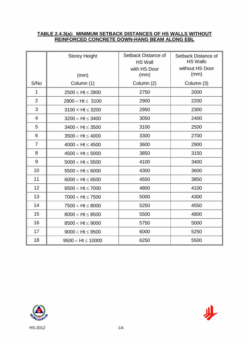
TABLE 2.4.3(a): MINIMUM SETBACK DISTANCES OF HS WALLS WITHOUT REINFORCED CONCRETE DOWN-HANG BEAM ALONG EBL
Storey Height
(mm)
Setback Distance of HS Wall
with HS Door (mm)
Setback Distance of HS Walls
without HS Door (mm)
S/No Column (1) Column (2) Column (3)
1 2500 ≤ Ht ≤ 2800 2750 2000
2 2800 < Ht ≤ 3100 2900 2200
3 3100 < Ht ≤ 3200 2950 2300
4 3200 < Ht ≤ 3400 3050 2400
5 3400 < Ht ≤ 3500 3100 2500
6 3500 < Ht ≤ 4000 3300 2700
7 4000 < Ht ≤ 4500 3600 2900
8 4500 < Ht ≤ 5000 3850 3150
9 5000 < Ht ≤ 5500 4100 3400
10 5500 < Ht ≤ 6000 4300 3600
11 6000 < Ht ≤ 6500 4550 3850
12 6500 < Ht ≤ 7000 4800 4100
13 7000 < Ht ≤ 7500 5000 4300
14 7500 < Ht ≤ 8000 5250 4550
15 8000 < Ht ≤ 8500 5500 4800
16 8500 < Ht ≤ 9000 5750 5000
17 9000 < Ht ≤ 9500 6000 5250
18 9500 < Ht ≤ 10000 6250 5500

HS-2012 -15-
TABLE 2.4.4(a): MINIMUM SETBACK DISTANCES OF HS WALLS WITH
REINFORCED CONCRETE DOWN-HANG BEAM ALONG EBL
Effective Storey Height*
(mm)
Setback Distance of HS Wall
With HS Door (mm)
Setback Distance of HS Walls
without HS Door (mm)
S/No Column (1) Column (2) Column (3)
1 Ht < 2200 2750 1800
2 2200 ≤ Ht ≤ 2800 2750 2000
3 2800 < Ht ≤ 3100 2900 2200
4 3100 < Ht ≤ 3200 2950 2300
5 3200 < Ht ≤ 3400 3050 2400
6 3400 < Ht ≤ 3500 3100 2500
7 3500 < Ht ≤ 4000 3300 2700
8 4000 < Ht ≤ 4500 3600 2900
9 4500 < Ht ≤ 5000 3850 3150
10 5000 < Ht ≤ 5500 4100 3400
11 5500 < Ht ≤ 6000 4300 3600
12 6000 < Ht ≤ 6500 4550 3850
13 6500 < Ht ≤ 7000 4800 4100
14 7000 < Ht ≤ 7500 5000 4300
15 7500 < Ht ≤ 8000 5250 4550 16 8000 < Ht ≤ 8500 5500 4800 17 8500 < Ht ≤ 9000 5750 5000 18 9000 < Ht ≤ 9500 6000 5250 19 9500 < Ht ≤ 10000 6250 5500
*Effective Storey Height = Storey Height – Depth ‘d’ of Down-hang Beam. Refer to Figure 2.4.4(a).

HS-2012 -16-
TABLE 2.4.5(a): MINIMUM SETBACK DISTANCES OF BASEMENT HS WALLS (FACING REINFORCED CONCRETE BASEMENT STOREY WALLS WITH OPENING)
Storey Height
(mm)
Setback Distance of HS Wall
with HS Door (mm)
Setback Distance of HS Walls
without HS Door (mm)
S/No Column (1) Column (2) Column (3)
1 2500 ≤ Ht ≤ 2800 2750 2000
2 2800 < Ht ≤ 3100 2900 2200
3 3100 < Ht ≤ 3200 2950 2300
4 3200 < Ht ≤ 3400 3050 2400
5 3400 < Ht ≤ 3500 3100 2500
6 3500 < Ht ≤ 4000 3300 2700
7 4000 < Ht ≤ 4500 3600 2900
8 4500 < Ht ≤ 5000 3850 3150
9 5000 < Ht ≤ 5500 4100 3400
10 5500 < Ht ≤ 6000 4300 3600
11 6000 < Ht ≤ 6500 4550 3850
12 6500 < Ht ≤ 7000 4800 4100
13 7000 < Ht ≤ 7500 5000 4300
14 7500 < Ht ≤ 8000 5250 4550
15 8000 < Ht ≤ 8500 5500 4800
16 8500 < Ht ≤ 9000 5750 5000
17 9000 < Ht ≤ 9500 6000 5250
18 9500 < Ht ≤ 10000 6250 5500

HS-2012 -17-
FIGURE 2.2.1(a) EXAMPLES OF HS OF DIFFERENT SHAPES (FOR GFA = 100 m2, HS SIZE = 2.8 m2, NUMBER OF SQUARE UNITS = 5)

HS-2012 -18-
FIGURE 2.2.2(a) HS CLEAR HEIGHT IN NON-LANDED AND LANDED DEVELOPMENTS

HS-2012 -19-
FIGURE 2.2.2(b) SECTION OF HS TOWER SHOWING HS AND NS CLEAR HEIGHTS
HS-2012 -20-
FIGURE 2.3.1(c) INTERNAL COMMON WALL BETWEEN TWO HS IN NON-LANDED AND LANDED CLUSTER HOUSING DEVELOPMENTS
HS-2012 -21-
FIGURE 2.3.1(d) SEPARATE WALLS BETWEEN TWO HS IN INTERMEDIATE LANDED DEVELOPMENTS

HS-2012 -22-
FIGURE 2.3.2 HS TOWER SHOWING HS AND NS (WITH ENCLOSED AND NON-ENCLOSED NS WALL) SLAB THICKNESS
HS-2012 -23-
FIGURE 2.3.2(f) MINIMUM DIMENSIONS OF CEILING SLAB FOR HS IN LANDED DEVELOPMENT

HS-2012 -24-
FIGURE 2.4.1(b) HS WALL ABUTTING AN AIR WELL IN A LANDED DEVELOPMENT

HS-2012 -25-
FIGURE 2.4.2(a) SCHEMATIC SECTION OF HS TOWER

HS-2012 -26-
FIGURE 2.4.2(b) HS TOWER WITH TWO LARGER HS AT THE TOP

HS-2012 -27-
FIGURE 2.4.3a (i) REQUIREMENT ON SETBACK DISTANCE OF HS WALLS (WITHOUT DOWN-HANG BEAM)
(STOREY HEIGHT ≤ 2800 mm) (FOR OTHER STOREY HEIGHTS, SEE TABLE 2.4.3(a))

HS-2012 -28-
FIGURE 2.4.3a (ii) SETBACK DISTANCE OF HS WALLS (WITHOUT DOWN-HANG BEAM)

HS-2012 -29-
FIGURE 2.4.3(c) USAGE OF TRELLIS (RC/STEEL HOLLOW SECTIONS) TO MAKE UP FOR SHORTFALL IN SETBACK DISTANCE

HS-2012 -30-
FIGURE 2.4.4(a) REQUIREMENT ON SETBACK DISTANCE OF
HS WALLS (WITH DOWN-HANG BEAM) (EFFECTIVE STOREY HEIGHT = STOREY HEIGHT – DEPTH ‘d’ OF DOWN-HANG BEAM)

HS-2012 -31-
FIGURE 2.4.4(b) DOWN-HANG BEAM LOCATED AWAY FROM EXTERNAL BUILDING LINE

HS-2012 -32-
FIGURE 2.4.5(a) PLAN OF A BASEMENT HS
FIGURE 2.4.5(b) PLAN OF A BASEMENT HS (WITH HS DOOR FACES RC BASEMENT STOREY WALL)

HS-2012 -33-
FIGURE 2.4.5(c) SECTIONAL VIEW OF A BASEMENT HS

HS-2012 -34-
FIGURE 2.4.6(a) HS LOCATED NEXT TO LIFT SHAFT
FIGURE 2.4.6(b) HS LOCATED NEXT TO REFUSE CHUTE AND RISER
HS-2012 -35-
FIGURE 2.5.1(a) HS DOOR FRAME WITH SINGLE DOOR REBATE
FIGURE 2.5.1(b) HS DOOR FRAME WITH DOUBLE DOOR REBATES

HS-2012 -36-
FIGURE 2.5.2(a) CONCRETE WALL SEGMENT AT HS DOOR
FIGURE 2.5.2(e) HS DOOR KERB
HS-2012 -37-
FIGURE 2.5.3 REQUIREMENTS FOR STRENGTHENED CEILING SLAB IN FRONT OF HS DOOR IN NON-LANDED DEVELOPMENT

HS-2012 -38-
FIGURE 2.6.1(c) FIXTURES IN HS

HS-2012 -39-
FIGURE 2.7.1(a) HS TOWER

HS-2012 -40-
FIGURE 2.8.1(a) SHIELDING OF TRANSFER STRUCTURES SUPPORTING HS TOWER

HS-2012 -41-
FIGURE 2.8.1(b) SHIELDING OF TRANSFER SLAB/BEAMS/EXTERIOR COLUMNS/WALLS

HS-2012 -42-
FIGURE 2.9 HS BENEATH AN INTERNAL STAIRCASE

HS-2012 -43-
FIGURE 2.12 DETAILS OF WALL RECESS FOR HS DOOR HANDLE

HS-2012 -44-
CHAPTER 3: STRUCTURAL REQUIREMENTS 3.1 GENERAL
The structural design of the HS tower shall take into account both the vertical and lateral loads, where applicable.
The HS tower shall be designed for maximum degrees of redundancy in the structural system against weapon effects.
3.2 MATERIALS
3.2.1 Concrete
The minimum grade of concrete for all HS elements shall be Grade 30. The use of prestressed concrete for the HS tower, and the transfer structure and its supporting walls and columns is not permitted.
3.2.2 Steel Reinforcement
The steel reinforcement of concrete shall be welded steel fabric mesh and hot rolled steel bars. The minimum yield stress for the main reinforcements and shear links in the structural elements forming the HS or NS shall be 460 N/mm2 and 250 N/mm2 respectively.
3.3 ANALYSIS
3.3.1 General
The vertically continuity of HS and NS walls, where applicable, to the foundation shall comply with clause 2.4.2. 3.3.2 Beam Supported on HS wall The end of the beam that is supported on HS wall shall be designed and detailed as simply support. This requirement shall only apply to HS in non-landed houses. 3.3.3 Shielded NS walls and/or NS columns
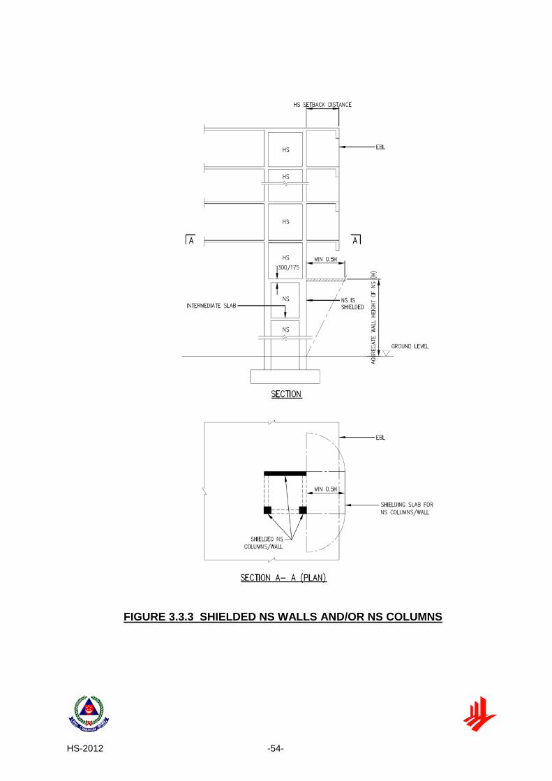
No additional design checks on HS tower is required if its supporting NS elements,
wall(s), column(s) or any of its combination, are shielded. These structural elements are deemed adequately shielded if reinforced concrete slab or other equivalent structural forms provided above them is extended beyond their edges by

HS-2012 -45-
a minimum length of 0.5H, where H is the aggregate wall height of NS (See FIGURE 3.3.3).
3.3.4 Unshielded NS Wall(s) and/or NS Columns The following requirements are to be complied with if the design adopts:
(a) Unshielded NS Wall(s)
The minimum thickness of each NS wall shall be 300 mm. The HS tower shall be designed against the most severe effects as the result of the removal of a portion of the NS wall equivalent to an opening of 1500 mm diameter on the NS wall at its most critical location (See FIGURE 3.3.4(a)).
(b) Unshielded NS Column(s)
The minimum size (either its diameter or the shorter dimension) of NS column shall be 500 mm. The HS tower shall be designed against the most severe effects as the result of the removal of any one NS column (See FIGURE 3.3.4(b)).
(c) Combination of Unshielded NS Wall(s) and NS Column(s)
The minimum thickness of each NS wall and minimum size (either its diameter or the shorter dimension) of NS column shall be 300 mm and 500 mm respectively. The HS tower shall be designed against the most severe effects as the result of the following (See FIGURE 3.3.4(c)):
(i) Removal of a portion of the NS wall equivalent to an opening of 1500
mm diameter on the NS wall at its most critical location and
(ii) Removal of any one NS column at a time. The above removal of wall or column shall be considered one at a time.
(d) The following criteria are to be used when performing design checks for
Clause 3.3.4(a), 3.3.4(b) or 3.3.4(c):
(i) The design loads shall be based on the load combination and values of partial safety factors for loads (γf) in accordance with TABLE 3.3.4.
(ii) The design strength for a given material is derived from the
characteristic strength divided by the partial safety factor for strength of material (γm), which shall be 1.3 for concrete and 1.0 for reinforcement.
HS-2012 -46-
3.3.5 Transfer Structure Supporting HS Tower 3.3.5.1 Design Against Collapse Load The design loads for the transfer structure shall include a collapse load of 20kN/m2 acting on transfer slab/beam. An additional load combination in the design, incorporating the collapse load, shall be considered with partial safety factors for loads (γf) given in Table 3.3.5.1. Only one transfer of HS loads in each tower by the transfer structure to its supporting columns and/ or walls is allowed. Multiple transfers of HS load in the same HS tower is not allowed. See FIGURE 2.8.1(c). 3.3.5.2 Shielded Transfer Structure No additional design checks on transfer structure are required, besides the requirement in Clause 3.3.5.1, if the transfer structures are shielded by RC slab or other equivalent structural forms. The transfer structure is deemed adequately shielded if Clause 3.3.5.2(a) and 3.3.5.2(b) are complied with:
(a) Shielding of Transfer slab/beams
The transfer slab/beams are deemed to be shielded if RC shielding slab or other equivalent structural forms is provided directly above the transfer slab/beams and is extended beyond their external edges by a minimum length of 0.5H1, where H1 is the vertical distance between the top level of the RC shielding slab and the soffit of transfer slab/beams (See FIGURE 3.3.5.2(a)).
(b) Shielding of Exterior Columns
The transfer columns are deemed to be shielded if RC shielding slab or other equivalent structural forms is provided above the exterior columns and is extended beyond their exterior edges by a minimum length of 0.5H2 or 0.5H3, where H2 and H3 are the vertical distances between the top level of the RC shielding slab and the base of the exterior columns (See FIGURE 3.3.5.2(a)).
3.3.5.3 Unshielded Transfer Structure
Besides the requirement in Clause 3.3.5.1, additional design checks on unshielded transfer structure (See FIGURE 3.3.5.3) shall be carried out in accordance with the following requirements:
(a) Unshielded Transfer Slab/Beams
The transfer structure shall be designed against the most severe effects as

HS-2012 -47-
the result of the removal of a portion of the transfer slab/beam equivalent to an opening of 1500 mm diameter on the transfer slab/beams at its most critical location (See FIGURE 3.3.5.3a (i) and FIGURE 3.3.5.3a (ii)).
(b) Unshielded Exterior Columns and Walls
The minimum size (either its diameter or shorter dimension) of the exterior columns shall be 500 mm and the minimum thickness of the wall shall be 300mm. The transfer structure shall be designed against the most severe effects as the result of the removal of any one exterior column at a time or the removal of a portion of the exterior wall equivalent to an opening of 1500 mm diameter on the transfer wall at its most critical location. Alternative path for load transfer shall be designed for such cases (See FIGURE 3.3.5.3b (i) and FIGURE 3.3.5.3b (ii)).
(c) The following are the criteria to be used when performing design checks for
Clause 3.3.5.3(a) and 3.3.5.3(b):
(i) The design loads including collapse load, shall be based on the load combination and values of partial safety factors for loads (γf) in accordance with Table 3.3.5.3.
(ii) The design strength for a given material is derived from the
characteristic strength divided by the partial safety factor for strength of material (γm), which shall be 1.3 for concrete and 1.0 for reinforcement.
3.4 MEMBER DIMENSIONS AND REINFORCEMENT REQUIREMENTS
3.4.1 Member Dimensions The minimum member size of HS and NS shall be as stipulated in Chapter 2 – Architectural Design. 3.4.2 Reinforcement Requirements
All diameters of reinforcement specified hereinafter shall refer to minimum bar diameters. All spacing of reinforcement specified hereinafter shall refer to maximum spacing of reinforcement in both directions.
3.4.2.1 Wall Reinforcements of HS and NS
(a) Minimum Reinforcement in HS walls in landed development – refer to TABLE
3.4.2.1(a).
(b) Minimum Reinforcement in HS or NS walls in non-landed development – refer to TABLE 3.4.2.1(b).

HS-2012 -48-
(c) Reinforcements at both faces of the internal common wall shall be T10-100 c/c in both directions. The shear links shall be R6-600 c/c in both directions.
3.4.2.2 Slab Reinforcements of HS and NS Top and bottom reinforcements of the slab shall be T10-100 c/c in both directions. The shear links shall be R6-600 c/c in both directions. 3.4.2.3 Ceiling Slab Immediately Outside the HS
(a) The ceiling slab immediately outside the HS wall with HS door shall be
constructed of reinforced concrete. Two layers of reinforcement bars (top and bottom) of T10-100mm c/c in both directions shall be provided for the ceiling slab with minimum 125mm thick.
(b) The reinforcements of every floor slab immediately outside HS tower walls shall be structurally connected to HS tower.
3.4.2.4 HS Slab Which Is Integrated With Pile-Cap/ Footing
For HS slab integrated with the pile-cap or footing of more than 500 mm thick, shear links is not required. The maximum spacing of main reinforcement shall be 200 mm c/c.
3.5 DETAILING OF HS TOWER
3.5.1 General
The HS tower is to be detailed to allow for the installation of services and fixtures in HS and to resist spalling of the internal face of HS walls, soffit of ceiling slabs and/or finishes on HS floor slab. 3.5.2 Lap and Anchorage Length
Requirements for lap and anchorage length of reinforcement bars are as follows:
(a) For slabs and walls, full tension lap length shall be provided at all laps. The
lap length shall be at least equal to the design tension length necessary to develop the full tensile capacity of the reinforcement. The lap length shall take into account the minimum cover, location and strength of the lapped reinforcement and the concrete grade.

HS-2012 -49-
(b) Welding of reinforcement bars to attain tension anchorage length or tension
lapped length is not permitted.
(c) Bundled bars are not permitted.
3.5.3 Concrete Cover
The concrete cover to the main reinforcement shall not exceed 40 mm.
3.5.4 Cast-In-Situ and Precast Elements
Cast-In-Situ HS elements shall comply with the dimensions and detailed requirements as shown in the following figures:
• FIGURE 3.5.4 (a) - Plan of HS
• FIGURE 3.5.4 (b) - Sectional details of HS slabs/walls
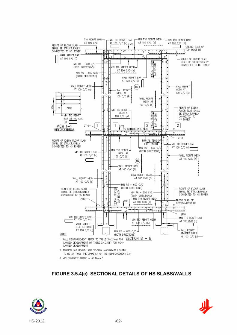
• FIGURE 3.5.4 (c) - Sectional details of HS slabs/walls
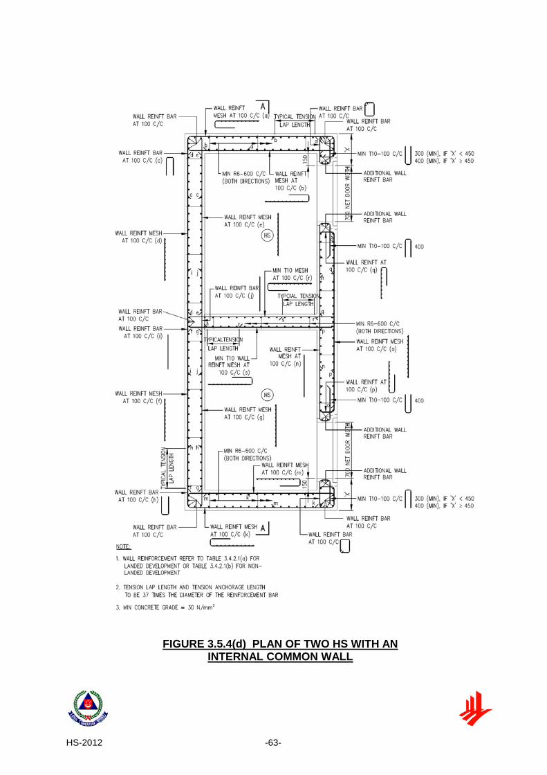
• FIGURE 3.5.4 (d) - Plan of two HS with an internal common wall
• FIGURE 3.5.4 (e) - Sectional details of two HS with an internal common wall
• FIGURE 3.5.4 (f) - Details of HS wall reinforcement bar near HS door
• FIGURE 3.5.4 (g) - Typical details of embedded conduit in HS wall
• FIGURE 3.5.4 (h) - Typical details of trimmer bars for ventilation sleeve
• FIGURE 3.5.4 (i) Typical details of trimmer bars for wall recess
• FIGURE 3.5.4 (j) - Details of shear links in HS slabs/walls
Pre-cast HS elements shall comply with the dimensions and detailed requirements as shown in the following figures:
• FIGURE 3.5.4 (k) - Plan of HS with pre-cast HS door frame panel (Type
1)
• FIGURE 3.5.4 (l) - Details and Sections of pre-cast HS door frame panel with ventilation sleeve above it (Type 1)
• FIGURE 3.5.4 (m) - Sections of pre-cast HS door frame panel with ventilation sleeve above it (Type 1)
• FIGURE 3.5.4 (n) - Details and Sections of pre-cast HS door frame panel with ventilation along its side (Type 1)
• FIGURE 3.5.4 (o) - Sections of pre-cast HS door frame panel with ventilation along its side (Type 1)

HS-2012 -50-
• FIGURE 3.5.4 (p) - Plan of HS with pre-cast HS door frame panel (Type 2)
• FIGURE 3.5.4 (q) - Details and sections of pre-cast HS door frame panel with ventilation sleeve above it (Type 2)
• FIGURE 3.5.4 (r) - Sections of pre-cast HS door frame panel with ventilation sleeve above it (Type 2)
• FIGURE 3.5.4 (s) - Details and sections of pre-cast HS door frame panel with ventilation along its side (Type 2)
• FIGURE 3.5.4 (t) - Sections of pre-cast HS door frame panel with ventilation along its side (Type 2)
• FIGURE 3.5.4 (u) - Plan of HS with pre-cast HS door frame panel (Type 3)
• FIGURE 3.5.4 (v) - Details of pre-cast HS door frame panel (Type 3)
• FIGURE 3.5.4 (w) - Sections of pre-cast HS door frame panel (Type 3)
• FIGURE 3.5.4 (x) - Sections of pre-cast HS door frame panel (Type 3)
3.5.5 Joints
(a) Construction joints in an HS tower shall be properly executed to ensure that
the strength and the integrity of the HS are not impaired. The type and location of joints shall be specified in the design after taking into account the following:
(i) A concrete kicker, if provided, shall not be more than 100 mm high.
(ii) All HS walls located within each storey shall be cast in one operation.
(b) Expansion joints or contraction joints in the HS tower are not permitted.
3.6 PENETRATION OF SERVICES 3.6.1 Electrical Services (a) All service conduits shall not penetrate through the walls and slabs of the
HS. Service conduits for electrical and communication fixtures which are located at external HS walls can be embedded in the HS wall. Other than this, all service conduits which do not serve the HS shall not be embedded within the HS walls and slabs.
(b) Two cast-in service outlets located directly back to back on the internal and
external faces of the HS wall are not permitted (See FIGURE 3.6.1(b)).

HS-2012 -51-
Service outlets shall be fixed with at least a clear distance of 300 mm between each other (See FIGURE 2.12).
(c) Risers for services can be mounted on the external face of HS tower walls.
(d) Where service cables and fixtures in the HS are exposed on internal walls,
non-metallic inserts are to be used for their mounting. For embedded service cables and fixtures serving the HS, the details as shown in FIGURE 3.5.4(g) shall be followed. The encasement for the switch, 13A switched socket outlet, TV, radio and telephone outlets of Clause 2.6 shall be made of hot-dipped galvanised steel construction (See FIGURE 3.6.1(d)).
(e) A maximum of 4 numbers of 25 mm diameter conduits are allowed to be
embedded within the HS walls for electrical cables serving fixtures in the HS. Both ends of these conduits on the internal and the external of the HS shall be fully sealed with sealing material in accordance with the manufacturer’s specification and up to a depth of not less than 100 mm into the conduits to ensure air-tightness of HS.
(f) Where an HS or NS share a common wall with lift shaft or services risers,
material used for connection of services on the common wall shall be made of stainless steel. For the purpose of installing M&E equipment in the lift core or services risers, cast-in bar with threaded end or anchor bolts shall be used in this common wall. Where anchor bolts are used, it shall be installed according to manufacturer’s technical specification. The spacing of the anchor bolts, measured between their centrelines, shall be more than 300 mm.
3.6.2 Water and Gas Services (a) Service pipes for water or gas are allowed to penetrate through the HS walls
provided that they are laid inside a stainless steel casing encased by 150 mm reinforced concrete all round (See FIGURE 3.6.2(a)). Joints in water pipe, gas pipe or the stainless steel conduit shall be located outside the HS.
(b) Risers for water and gas services can be mounted on the external face of
HS walls.

HS-2012 -52-
TABLE 3.3.4: LOAD COMBINATION AND VALUES OF PARTIAL SAFETY FACTORS (γf) FOR ULTIMATE LIMIT STATE
(Unshielded NS Walls, Unshielded NS Columns or a Combination of Unshielded NS Walls and NS Columns)
Load Combination
Load Types
Dead Imposed Earth and Water Pressure Wind
Adverse Beneficial Adverse Beneficial Dead and imposed and wind (and earth and water pressure)
1.05
1.05
1.05
1.05
1.05
1.05
TABLE 3.3.5.1: LOAD COMBINATION AND VALUES OF PARTIAL SAFETY FACTORS
(γf) FOR ULTIMATE LIMIT STATE (Design against Collapse Load and Unshielded/Shielded Transfer Structure)
Load Combination
Load Types
Dead Imposed Earth and Water
Pressure Wind Collapse
Adverse Beneficial Adverse Beneficial Dead and imposed and wind and collapse load (and earth and water pressure)
1.2
1.2
1.2
1.2
1.2
1.2
1.05
TABLE 3.3.5.3: LOAD COMBINATION AND VALUES OF PARTIAL SAFETY FACTORS
(γf) FOR ULTIMATE LIMIT STATE (Unshielded Transfer Structure)
Load Combination
Load Types
Dead Imposed Earth and Water
Pressure Wind Collapse
Adverse Beneficial Adverse Beneficial Dead and imposed and wind and collapse load (and earth and water pressure)
1.05
1.05
1.05
1.05
1.05
1.05
1.05

HS-2012 -53-
TABLE 3.4.2.1(a): MINIMUM REINFORCEMENT OF HS WALLS FOR LANDED DEVELOPMENTS
HS Clear Height (mm)
Reinforcements at both internal and external
faces of wall (both directions)
Shear Links (both directions)
2400 ≤ Ht ≤ 3900 T10 - 100 R6 - 600
TABLE 3.4.2.1(b): MINIMUM REINFORCEMENT OF HS OR NS WALLS FOR NON-LANDED DEVELOPMENTS
HS or NS Clear Height (mm)
Reinforcements at both internal and external
faces of wall (both directions)
Shear Links (both directions)
2400 ≤ Ht ≤ 3000 T10 - 100 R6 - 600
3000 < Ht ≤ 3900 T13 - 100 R6 - 600
HS-2012 -54-
FIGURE 3.3.3 SHIELDED NS WALLS AND/OR NS COLUMNS

HS-2012 -55-
FIGURE 3.3.4(a) UNSHIELDED NS WALL(S)
FIGURE 3.3.4(b) UNSHIELDED NS COLUMN(S)
FIGURE 3.3.4(c) COMBINATION OF UNSHIELDED NS WALL(S) AND/OR NS COLUMN(S)

HS-2012 -56-
FIGURE 3.3.5.2(a) SHIELDED TRANSFER SYSTEM THAT SUPPORTS HS TOWER

HS-2012 -57-
FIGURE 3.3.5.3 UNSHIELDED TRANSFER SYSTEM THAT SUPPORTS HS TOWER
(UNSHIELDED SLAB/BEAM OR/AND COLUMNS/WALLS)

HS-2012 -58-
FIGURE 3.3.5.3a (i) UNSHIELDED TRANSFER BEAMS
FIGURE 3.3.5.3a (ii) UNSHIELDED TRANSFER SLAB

HS-2012 -59-
FIGURE 3.3.5.3b (i) UNSHIELDED TRANSFER WALLS
FIGURE 3.3.5.3b (ii) UNSHIELDED TRANSFER COLUMNS

HS-2012 -60-
FIGURE 3.5.4(a) PLAN OF HS

HS-2012 -61-
FIGURE 3.5.4(b) SECTIONAL DETAILS OF HS SLABS/WALLS
HS-2012 -62-
FIGURE 3.5.4(c) SECTIONAL DETAILS OF HS SLABS/WALLS
HS-2012 -63-
FIGURE 3.5.4(d) PLAN OF TWO HS WITH AN INTERNAL COMMON WALL

HS-2012 -64-
FIGURE 3.5.4(e) SECTIONAL DETAILS OF TWO HS WITH AN INTERNAL COMMON WALL

HS-2012 -65-
FIGURE 3.5.4(f) DETAILS OF HS WALL REINFORCEMENT BAR NEAR HS DOOR

HS-2012 -66-
FIGURE 3.5.4(g) TYPICAL DETAILS OF EMBEDDED CONDUIT IN HS WALL

HS-2012 -67-
FIGURE 3.5.4(h) TYPICAL DETAILS OF TRIMMER BARS FOR VENTILATION SLEEVE
FIGURE 3.5.4(i) TYPICAL DETAILS OF TRIMMER BARS FOR WALL RECESS

HS-2012 -68-
FIGURE 3.5.4(j) DETAILS OF SHEAR LINKS IN HS SLABS/WALLS

HS-2012 -69-
FIGURE 3.5.4(k) PLAN OF HS WITH PRE-CAST HS DOOR FRAME PANEL (TYPE 1)

HS-2012 -70-
FIGURE 3.5.4(l) DETAILS AND SECTIONS OF PRE-CAST HS DOOR FRAME PANEL WITH VENTILATION SLEEVE ABOVE IT (TYPE 1)

HS-2012 -71-
FIGURE 3.5.4(m) SECTIONS OF PRE-CAST HS DOOR FRAME PANEL WITH VENTILATION SLEEVE ABOVE IT (TYPE 1)

HS-2012 -72-
FIGURE 3.5.4(n) DETAILS AND SECTIONS OF PRE-CAST HS DOOR FRAME PANEL WITH VENTILATION SLEEVE ALONG ITS SIDE (TYPE 1)

HS-2012 -73-
FIGURE 3.5.4(o) SECTIONS OF PRE-CAST HS DOOR FRAME PANEL WITH VENTILATION SLEEVE ALONG ITS SIDE (TYPE 1)
HS-2012 -74-
FIGURE 3.5.4(p) PLAN OF HS WITH PRE-CAST HS DOOR FRAME PANEL (TYPE 2)

HS-2012 -75-
FIGURE 3.5.4(q) DETAILS AND SECTIONS OF PRE-CAST HS DOOR FRAME PANEL WITH VENTILATION SLEEVE ABOVE IT (TYPE 2)

HS-2012 -76-
FIGURE 3.5.4(r) SECTIONS OF PRE-CAST HS DOOR FRAME PANEL WITH VENTILATION SLEEVE ABOVE IT (TYPE 2)

HS-2012 -77-
FIGURE 3.5.4(s) DETAILS AND SECTIONS OF PRE-CAST HS DOOR FRAME PANEL WITH VENTILATION SLEEVE ALONG ITS SIDE (TYPE 2)
HS-2012 -78-
FIGURE 3.5.4(t) SECTIONS OF PRE-CAST HS DOOR FRAME PANEL WITH VENTILATION SLEEVE ALONG ITS SIDE (TYPE 2)

HS-2012 -79-
FIGURE 3.5.4(u) PLAN OF HS WITH PRE-CAST DOOR FRAME PANEL (TYPE 3)

HS-2012 -80-
FIGURE 3.5.4(v) DETAILS OF PRE-CAST HS DOOR FRAME PANEL (TYPE 3)

HS-2012 -81-
FIGURE 3.5.4(w) SECTIONS OF PRE-CAST HS DOOR FRAME PANEL (TYPE 3)

HS-2012 -82-
FIGURE 3.5.4(x) SECTIONS OF PRE-CAST HS DOOR FRAME PANEL (TYPE 3)
HS-2012 -83-
FIGURE 3.6.1(b) MOUNTING OF SERVICES ON EXTERNAL WALL OF A HS

HS-2012 -84-
FIGURE 3.6.1(d) TYPICAL DETAILS OF EMBEDDED SOCKET/SWITCH

HS-2012 -85-
FIGURE 3.6.2(a) ENCASEMENT DETAILS OF WATER/GAS SERVICE PIPES PENETRATING THROUGH HS WALLS

HS-2012 -86-
CHAPTER 4: VENTILATION SLEEVES 4.1 GENERAL
Two 125 mm diameter ventilation sleeves shall be cast into the wall/s of each HS. 4.2 POSITION The position of each ventilation sleeve shall comply with the following (See
FIGURE 4.2(a) and 4.2(b)):
(a) The height of each opening of ventilation sleeve, measured from the centre of the opening to internal FFL of the HS shall be between 1900 mm and 3600 mm;
(b) The ventilation sleeve shall be positioned such that there is sufficient
clearance from any structural elements and services. The centre of the ventilation sleeve to the soffit of ceiling and the nearest face of the internal HS walls shall be at least 300 mm;
(c) Where the ventilation sleeve is placed above or adjacent to the HS door
frame, the centre of the ventilation sleeve shall be at least 250 mm from the nearest edge of the door frame; and
(d) The shortest distance between the centres of the two ventilation sleeves
shall be at least 1000 mm.
4.3 ACCESSIBILITY OF VENTILATION SLEEVES 4.3.1 Clearance in front of and around Fragmentation Plate
The minimum clearance from the fragmentation plate to RC beam or structure or service shall be 50 mm. Where the RC beam or structure or service is fronting the fragmentation plate of ventilation sleeve, the clear distance between them shall be at least 500 mm. See FIGURE 4.3.1.
4.3.2 False Ceiling below Ventilation Sleeves
Where false ceilings are provided outside the HS and below the ventilation sleeves, there shall be perforated access panels of minimum size of 600 mm x 600 mm positioned directly below each ventilation sleeve. See FIGURE 4.3.2.

HS-2012 -87-
4.4 FRAGMENTATION PLATE
Each ventilation sleeve shall have a 6 mm thick stainless steel fragmentation plate mounted on the external face using 10 mm stainless steel bolts (See FIGURE 4.4).

HS-2012 -88-
FIGURE 4.2(a) POSITION OF VENTILATION SLEEVES

HS-2012 -89-
FIGURE 4.2(b) SECTIONAL VIEWS OF VENTILATION SLEEVES

HS-2012 -90-
FIGURE 4.3.1 MINIMUM CLEARANCE FOR FRAGMENTATION PLATE
FIGURE 4.3.2 PERFORATED ACCESS PANEL BELOW VENTILATION SLEEVE

HS-2012 -91-
FIGURE 4.4 DETAILS OF VENTILATION SLEEVE AND FRAGMENTATION PLATE

HS-2012 -92-
CHAPTER 5: HS DOOR 5.1 GENERAL
The HS door shall provide an airtight closure to the HS, and shall be designed to open outwards from the HS. HS door frame that is cast together with the HS wall shall have single or double door rebate. See FIGURE 2.5.1(a) and FIGURE 2.5.1(b).
5.2 APPROVED HS DOOR
Only HS doors of an approved design, and which have been certified and listed under the Product Listing Scheme shall be used.
5.3 HS DOOR NOTICE
Every HS door shall have a HS door notice affixed on its internal face (See FIGURE 5.3(a)). A sample notice is shown in FIGURE 5.3(b).
5.4 SPECIFICATION OF HS DOOR NOTICE
(a) Manner of Application : To be affixed on the internal HS door by pressure sensitive and strong adhesive.
(b) Special Features : Non-brittle, rub and mar resistant, storage
stability and colour fastness under light. (c) Text, Lettering, Layout : Conform to sample notice. (d) Colours : Background is light yellow, lettering is black,
sub-headings, border and triangular logo area are red.

HS-2012 -93-
FIGURE 5.3(a) LOCATION OF NOTICE ON HS DOOR

HS-2012 -94-
FIGURE 5.3(b) SAMPLE HS DOOR NOTICE
HS-2012 -95-
CHAPTER 6: CONSTRUCTION AND COMMISSIONING 6.1 GENERAL
As the HS is designed to resist weapon effects, good workmanship is essential to achieve the designed protection level.
6.2 STRUCTURAL WORKS
The following shall be observed:
(a) Only the non-removable type of form-tie (form-tie without through opening) to secure formwork before casting of HS wall is permitted. Upon the removal of every recessible type of plastic cones from the form-tie, the recess shall be sealed with non-shrink grout. The use of reinforcement bar as form-tie is not permitted.
(b) To avoid bending, warping or displacement of HS door frame and
honeycombing due to inadequate compaction or leakage of cementitious grout, additional precaution to ensure adequate compaction shall be taken while casting the concrete near the HS door frame.
(c) All embedded items shall be placed and tightly secured in their intended location to ensure their stability during casting. Indiscriminate hacking and drilling of HS tower walls, ceiling slabs or floor slabs are not permitted.
(d) The exposed surfaces of HS walls and soffit of HS ceiling slabs shall be
cast with smooth concrete finish. A maximum of 2 mm thick skim coat on the internal face of the HS walls and ceiling slabs of HS is allowed.
(e) The concrete structural elements shall be adequately compacted to
ensure air-tightness. Concrete areas with segregation or honeycombing shall not be indiscriminately hacked and plastered back.
(f) Irregularities of exposed surfaces shall not be indiscriminately hacked and
plastered back.
(g) Method statement of the remedial work on structural elements, including HS door frame, shall be approved by the Commissioner of Building Control.

HS-2012 -96-
6.3 HS DOOR
The following shall be observed:
(a) Allowing an opening in the HS wall and later erecting the HS door frame and door leaf in this opening, followed by casting concrete around it is not permitted.
(b) When casting the HS wall with HS door frame, a dummy door leaf of
adequate design shall be placed to ensure the stability and prevent the bending, warping or displacement of the HS door frame during concreting.
(c) The FFL of the floor slab outside the HS shall be done such that the HS
door can be opened adequately for the peacetime use of the HS. 6.4 PEACETIME REQUIREMENT OF VENTILATION SLEEVES
For ventilation purposes during peacetime, at least 25% of total area of the two ventilation openings shall be kept uncovered.
6.5 COMMISSIONING REQUIREMENTS
All electrical and communication fixtures such as switch and lighting point, switched socket outlets, TV, radio and telephone outlets including HS door notice shall be provided inside the completed HS. The service conduits with electrical cables serving the HS shall be provided prior to commissioning.
A HS is considered commissioned only if the HS passes all the following tests in one inspection:
(a) Light penetration test of HS door – an acceptable test method to check on
light penetration into the HS is to use a torch-light from the exterior of HS door. The test is considered to have passed if no light could be seen from the inside of HS.
(b) Chalk mark test on the HS door – an acceptable test method is to apply chalk to the part of the door frame where the door seal will come into contact with when the door is closed. The test is considered to have passed if there is an unbroken and uniform transfer of the chalk markings onto the door seal when the door is closed and re-opened.

HS-2012 -97-
(c) Air-tightness test of the HS – an acceptable test method is to pressurise the HS and measure the rate of pressure drop or the pressure difference between the interior and exterior of the HS. The water manometer and the *pressure gauge can be used for the test as follows: (i) When using the water manometer, the HS is pressurised such that the
water level difference in manometer is 25 mm. The HS is considered to have passed the test if the water level difference in manometer is more than or equal to 5 mm after 45 seconds.
(ii) When using the pressure gauge, the HS is pressurised by pumping air
into the HS such that there is a pressure difference of 250 Pa* between inside and outside of HS. The HS is considered to have passed the test if the pressure gauge shows more than or equal to 50 Pa after 45 seconds.
The ventilation sleeves of the HS, which have been closed for the commissioning tests, shall be opened after the tests to comply with Clause 6.4 for ventilation during peacetime. *The pressure gauge used should have a dial size with a scale of 0 to 50mm or 0 to 500 Pa. (Note: 1 mm = 10 Pa).

HS-2012 -98-
CHAPTER 7: PERMITTED AND NOT PERMITTED WORKS TO HS TOWER
7.1 GENERAL
Any repair or alteration or renovation works, which are likely to weaken or damage any structural elements of the HS or NS, is not permitted.
7.2 PERMITTED AND NOT PERMITTED WORKS
7.2.1 Permitted Works to HS
(a) Laying of floor tiles bonded to wet cement mortar. The total thickness of floor finishes and screed is not to exceed 50mm.
(b) Laying of floor skirting tiles (up to a maximum of 100 mm high) by bonding them with wet cement mortar to HS walls.
(c) Laying of vinyl or linoleum flooring.
(d) Applying splatter dash or equivalent to the external face of HS walls only
to provide rough surface for feature wall panels or wall tiles installation.
(e) Painting of walls, ceiling or door. In the case of HS door, owners shall not cover up or paint over the HS door notice (See Clause 5.3), locking bolts or door seal. The old paint coat on door and door frame is to be removed prior to repainting to avoid increase paint thickness resulting in difficulty in closing and opening of the door. The new paint coat must be dried up completely before closing the door as wet or damp paint will cause the door/ rubber gasket to stick onto the door frame when opening the door.
(f) Painting on only the exterior face of the 6mm fragmentation stainless steel
plate of the ventilation sleeves.
(g) Drilling into internal face of HS walls and ceiling slabs to a depth of not more than 50mm to affix inserts and removable screws is allowed for. Fixtures such as pictures, posters, cabinets or shelves on internal face of HS walls will have to be removed by the owners within 48 hours upon notification. There is no restriction to the diameter of the non-metallic insert as long as it does not exceed 50mm in length. It is the owner’s responsibility to ensure that the strength of the insert is adequately provided for the intended purpose.
(h) Power driven nails are allowed only on external face of the HS walls to
facilitate flexibility in mounting of features/ fixtures by owners. The length of power driven nail shall not be more than 75 mm.

HS-2012 -99-
(i) Fragmentation plates (Clause 4.4) of the ventilation sleeves are allowed to be removed provided that the fragmentation plates and its bolts and nuts are mounted or kept together for use when needed. If the plate is to be mounted on the HS wall, it shall be done in accordance with Clause 7.2.1(g).
(j) Closing or covering up of ventilation openings by removable aesthetic or
architectural finishes is allowed, provided that at least 25% of the total area of the two openings shall be left uncovered for ventilation purposes during peacetime.
(k) The minimum clearance from the fragmentation plate to RC beam or
structure or service shall be 50 mm. Where the RC beam or structure or service is fronting the fragmentation plate of ventilation sleeve, the clear distance between them shall be at least 500 mm. See FIGURE 4.3.1.
(l) Where false ceilings are provided outside the HS and below the
ventilation sleeves, there shall be perforated access panels of minimum size of 600 mm x 600 mm positioned directly below each ventilation sleeve. See FIGURE 4.3.2.
7.2.2 Not Permitted Works to HS (a) Laying of wall tiles or spray of rock stone finish, cement sand finish and
gypsum plastering on the internal faces of HS walls.
(b) Laying of floor tiles using adhesive materials.
(c) Laying of 2nd layer of tiles on floor or skirting tiles.
(d) Installation of cornices within the HS.
(e) Installation works with fixings using power driven nails into the internal HS walls.
(f) Tampering with, removing or covering up of the HS door notice. The HS
door notice provides important information to the occupants on the use of the HS.
(g) Indiscriminate hacking and drilling of HS walls, floor slabs, and ceiling
slabs other than drilling permitted in Clause 7.2.1(g) and 7.2.1(h).
(h) Hacking to both internal and external face of the household shelter walls to form key for tiling.
(i) Hacking on external face of HS wall for mounting of feature wall panels or
wall tiles installation.

HS-2012 -100-
(j) Modifying, changing, removing or tampering of HS door.
(k) Modifying, altering or tampering with any part of the ventilation openings, plates and the mounting devices such as bolts and nuts.
(l) Painting to the interior face of the 6mm fragmentation stainless steel plate
of the ventilation sleeves, the ventilation sleeves, “O” ring rubber gaskets and the four or eight numbers of stainless steel bolts which hold the steel plate to the sleeves.
7.2.3 Not Permitted Works to NS
Indiscriminate hacking and drilling of NS walls, floor slabs and ceiling slabs are not permitted.