technical report development of application technology … · viously prevailed was pack...
TRANSCRIPT

NIPPON STEEL & SUMITOMO METAL TECHNICAL REPORT No. 116 SEPTEMbER 2017
- 14 -
1. IntroductionTransmission parts such as gears and CVT pulleys require high
performance regarding the wear resistance and strength for contact fatigue and bending fatigue, and therefore generally undergo carbu-rizing and quenching today. The surface treatment method that pre-viously prevailed was pack carburizing, a treatment that involves heating steel immersed in charcoal powder to a high temperature. It forced workers to work in a hazardous environment, and was not even productive After the 1950s, gas carburization in which steel is carburized in an accurately controlled CO atmosphere spread, and it still prevails. From the recent perspective of environmentally-con-scious manufacturing, however, the carburization treatment is also being advocated to reduce the CO2 emission, with vacuum carburiz-ing attracting attention for its advantageous efficiency.
Vacuum carburizing is a treatment that consists of at least one cycle each of the carburization period during which steel parts are heated under vacuum and a hydrocarbon gas is injected into the vac-uum carburizing furnace at low pressure, and the diffusion period in which the parts are held with vacuum to diffuse hydrocarbon only inside the steel. 1) Vacuum carburizing allows for high temperature carburization at 1 000°C or more under which steel can be held in the furnace with a higher diffusion coefficient than that when gas carburizing with the upper limit of approx. 950°C is used. Further-more, since hydrocarbon gases are thermally unstable, treatments need to be performed at low pressure in order to prevent soot and tar from forming, which assists the efficient entry of carbon into steel.
The carbon concentration near the surface often exceeds the solid solubility limit (hereinafter referred to as the “Acm line”) and cemen-tite (hereinafter referred to as “θ”) precipitates depending on the steel composition and temperature. This causes the carbon concen-tration gradient in austenite (hereinafter referred to as “γ”) to grow very large, increasing the diffusion flux in turn, allowing for deep carburization for a short time. 2) Moreover, since no oxide content is contained in the atmosphere, treated products have no incomplete-ly-quenched layer in the surface layer, meaning that higher strength than that obtained through gas carburizing can be achieved using vacuum carburizing.
There is, however, a problem in vacuum carburizing associated with the excessive carburization at the edges of the treated products. The excessive carburization causes coarse θ to be formed at the grain boundaries, which reduces the strength. A strength reduction also occurs due to an increase of residual γ with excessive carburi-zation, even without cementite precipitation. 3) In other words, even if incompletely-quenched layers are eliminated, poor edge strength makes the durability inferior to that required of an automobile part. Given this, we started to consider a method to render the excessive carburization at edges harmless rather than preventing it. This paper describes a method to eliminate the adverse effects of the excessive carburization by having fine θ precipitate in the excessively-carbu-rized portion.
Technical Report UDC 669 . 14 - 422 . 11 : 669 . 14 - 155 . 1 - 982 : 621 . 833
Development of Application Technology for Vacuum CarburizingShoji TODO* Hidekazu SUENOHideki IMATAKA
AbstractContrary to benefits of vacuum carburization, such as less carbon dioxide emission due
to higher processing temperature and efficiency, none of the control system for gas carbu-rizing was adapted to vacuum carburizing. To control carbon concentration profile, it was suitable for calculating the carbon flux from the gradient of chemical potential. Excess carburizing which occurs at the edge of machine parts decrease the fatigue property due to increase of the residual austenite and formation of coarse carbides. For the remedy of this disadvantage, new vacuum carburizing process was developed. We confirmed the fine car-bide dispersed in the case the carburizing followed by gas cooling, reheating and oil quench-ing is carried out at high temperature. Edge shape parts carburized by such process per-formed high fatigue property.
* Senior Researcher, Yawata R&D Lab. 1-1 Tobihata-cho, Tobata-ku, Kitakyushu City, Fukuoka Pref. 804-8501

NIPPON STEEL & SUMITOMO METAL TECHNICAL REPORT No. 116 SEPTEMbER 2017
- 15 -
2. Carbon Concentration Control MethodSince fatigue strength and wear resistance against bending and
torsion are expected for most carburized automobile parts, it is nec-essary to harden steel to a specified depth and to have an appropriate surface carbon concentration. For this reason, a method to optimize the carburization conditions for each part type and to accurately control the carbon concentration is required.
According to Morita, et al., 4) the carbon concentration is in-creased in the carburization period of vacuum carburizing until the surface enters an equilibrium state with the graphite. During a sub-sequent diffusion period in which the carbon supply from above the surface is stopped and carbon diffuses in the depth direction, the carbon concentration at the surface is declined. Thus, the carbon concentration is controlled by adjusting the durations of the carburi-zation period and diffusion period, while each part type has its own requisite carburization depth.
Figure 1 shows schematic views illustrating the concept of car-burization condition adjustment. First, the target carbon concentra-tion is determined for the surface and desired depth. Then, the car-bon concentration is examined using the heat patterns of a certain carburization period and diffusion period, and the durations of the carburization period and diffusion period are adjusted based on the difference from the target. If the carbon concentration is high at the surface and desired depth, the carburization period is shortened; if it is low, the carburization period is prolonged. If the differences be-tween the carbon concentration level and target are not the same at the surface and desired depth, the differences are adjusted by chang-ing the diffusion period duration. When the diffusion period is pro-longed, the carbon concentration at the surface is decreased. When it is shortened, the carbon concentration at the surface is increased. Since the change in the carbon concentration at the desired depth varies depending on how deep the desired depth is, it is necessary to change the two process parameters in a repetitive manner and evalu-ate them each time, in order to set optimum carburization condi-tions. If trials of optimum carburization conditions are conducted by repeatedly performing carburizing and analysis, enormous effort and time are required. In view of this, optimum carburization condi-tions need to be examined in simulations.
As described before, during vacuum carburizing, θ precipitates in the surface layer and alloy elements are distributed to θ and γ. The diffusion of carbon in the depth direction in γ and θ, which
starts from γ, is strongly influenced by the alloy elements contained in γ. For example, Si is not dissolved in θ, and Cr incrassates in θ. 5) Since Si increases the carbon activity while Cr decreases the same, the amount of θ precipitation is increased to distribute alloy ele-ments in θ and γ, and the carbon activity is increased. Figure 2 shows the carbon activity coefficient when SCR420 is carburized at 950°C. Thermodynamic calculation software Pandat 8.2 and the PanFe 2014 database were used. 6, 7) (Pandat was used for the ther-modynamic calculation described hereinafter.) The two-phase re-gion of γ and θ has a larger activity coefficient gradient than the γ single-phase region. The diffusion flux is represented by the follow-ing equation (1), 5) which includes a composition differential term of the activity coefficient,
J = −mx = −mRT {1 + x } (1)
where m is the carbon mobility and x is carbon mole-concentration. For gas carburizing during which no precipitation due to carburiza-tion generally occurs or in a negligible amount, if any, the diffusion flux is calculated from the gradient of carbon concentration. In con-trast, for vacuum carburizing with a large amount of θ precipitation, the change of the activity coefficient is not negligible. From the above, for simulating vacuum carburizing, equation (1) is differenti-ated to be solved using the diffusion drive force as the gradient of
∂μ∂z
∂ (ln γ)∂x
∂x∂z
Fig. 2 Activity coefficient of carbon referred to graphite in carburized steel SCR420 at 1 223 K
Fig. 1 Setting method for vacuum carburizing condition

NIPPON STEEL & SUMITOMO METAL TECHNICAL REPORT No. 116 SEPTEMbER 2017
- 16 -
chemical potential μ. Then, the carbon concentration distribution can be obtained under the condition that the law of mass conserva-tion is satisfied.
As shown in Fig. 3 and Fig. 4, we obtained the equilibrium state for each diffusion calculation step using regression equations writ-ten with respect to the results obtained in advance by the thermody-namic calculation software. This eliminated the need for thermody-namic equilibrium calculation for calculating the diffusion, reducing the calculation workload.
Figure 5 shows the carbon concentration distribution in an SCR420 round bar 26 mm in diameter that underwent vacuum car-burizing consisted of a one-hour carburization period, together with the simulation results. Figure 6 shows the carbon concentration dis-tribution in the same material that underwent vacuum carburizing consisted of a one-hour carburization period and a one-hour diffu-sion period, also together with the simulation results. The carbon concentration in a chip that was obtained by machining 0.05 mm into the surface layer for each vacuum carburized bar was analyzed. In the case of the vacuum carburizing with a one-hour carburization period, the carbon concentration at 0.05 mm deep in the surface lay-er reached approx. 2.0 mass% with a two-phase (γ-θ) structure formed; in the case of the vacuum carburizing with a one-hour car-burization period and a one-hour diffusion period, the carbon con-centration reached approx. 1.0 mass% with a single phase (γ) struc-
ture formed. In both carburization conditions, the results of calcula-tion that derived the diffusion flux from the chemical potential gra-dient were closer to the measurement values. Since a difference was seen only on the extreme surface layer with the vacuum carburizing with a one-hour carburization period, the amount of θ precipitation in the carburization period has a significant impact on the carbon concentration distribution after the diffusion. Accurate projection of the θ precipitation quantity in the carburization period is considered important.
3. Elimination of the Adverse Effects of Excessive Carburization
3.1 Control guidelines for excessively-carburized structuresFigure 7 shows the simulation results of a cross-section with
90° edge, using the method described above. The carburization con-ditions were: Temperature 950°C; a 28-minute carburization period; a 40-minute diffusion period; and cooling to 860°C at the rate of 0.05°C/s and quenching after 30-minute soaking. Whereas after the 28-minute carburization period, carbon uniformly penetrated from the surface, after the 40-minute diffusion period, and the carbon concentration was higher at the edge (upper left in the image) than on the flat portion surface, exceeding the Acm line. Furthermore, while at the quenching temperature of 860°C, the carbon concentra-tion at the flat portion was 0.8 mass%, it was approx. 1.8 mass% at the edge. The carbon concentration during vacuum carburizing in-creases to a point where it is in equilibrium with graphite in a carbu-
Fig. 3 Carbon concentration in γ-SCR420 at 1 223 K
Fig. 4 Chemical potential of carbon referred to graphite in SCR420 at 1 223 K
Fig. 5 Carbon profile of SCR420 carburized for 1 h at 1 223 K
Fig. 6 Carbon profile of SCR420 diffused 1 h after 1 h carburizing at 1 223 K

NIPPON STEEL & SUMITOMO METAL TECHNICAL REPORT No. 116 SEPTEMbER 2017
- 17 -
rization period, and then the carbon is diffused in the depth direction during a diffusion period, reducing the surface carbon concentration. However, at an edge, the diffusion fields collide with each other to hinder the carbon concentration from decreasing to a sufficient de-gree. This occurs when the surface carbon concentration in the car-burization period was higher than the target carbon concentration. As long as processing is conducted at 800°C or more, excessive car-burization at the edge is inevitable.
In view of this, we studied a method to eliminate the adverse ef-fects of excessive carburization. It is considered that the carbon con-centration at the edge exceeds the Acm line after the diffusion, and coarse θ precipitates, resulting in the deterioration of fatigue proper-ties. Given this, we studied a method to suppress the deterioration of fatigue properties by distributing fine θ. As a precipitate formed un-der high temperature tends to be coarse, it is desirable to form a γ single-phase structure under carburization temperatures.
Figure 8 shows a computational phase diagram of SCR420 us-ing the carbon concentration as a variable. From the diagram, under high temperature, when the Acm line is on the high carbon concentra-tion side and the carbon concentration of an excessively-carburized portion exceeds 1.5 mass%, it is necessary to set the carburizing temperature to 1 000°C or more to obtain a γ single-phase structure.
At the edge where excessive carburization occurred, a γ single-phase structure can be formed as well. However, if the material is hard-ened as-is, the high carbon concentration will cause a large amount of residual γ to be formed, rendering both hardness and strength low. For this reason, after the carburization and diffusion during which a γ single-phase structure is developed, the material is quickly cooled for suppressing the θ precipitation to develop the pearlite transfor-mation. Then, when the material is heated to the quenching tem-perature, in the excessively-carburized portion, ferrite (α) is trans-formed to γ while a part of θ in pearlite is melted, and a two-phase (γ-θ) structure is formed. After the material in this state is quenched, a hardened structure with diffused fine θ can be obtained.3.2 Strength properties of a product that has undergone the
measure for eliminating the excessive carburization adverse effectsNext, we studied the fatigue strength of a material in which fine
θ was distributed at the excessive carburization portion using a batch-type vacuum carburizing furnace as well as acetylene as the carburization gas. Figure 9 shows the heat pattern. We conducted both general vacuum carburizing at 950°C and vacuum carburizing at 1 040°C added with a process consisting of gas cooling, reheating to 860°C, and quenching for the purpose of eliminating the adverse
Fig. 8 Calculated phase diagram of SCR420 Fig. 9 Heat pattern of vacuum carburizing test (times in minute)
Fig. 7 Carbon distribution of carburized SCR420 at 1 223 K and soaked at 1 133 K
NIPPON STEEL & SUMITOMO METAL TECHNICAL REPORT No. 116 SEPTEMbER 2017
- 18 -
effects of excessive carburization. For the normal vacuum carburiz-ing, a SCM420 sample was vacuum carburized at 950°C. For the vacuum carburizing with a process for eliminating the excessive carburization adverse effects, a sample of high chromium steel was vacuum carburized at 1 040°C to form fine cementite. With the proc-ess for eliminating the excessive carburization adverse effects, which is conducted under high temperature, the total processing time is shortened by approx. 40%.
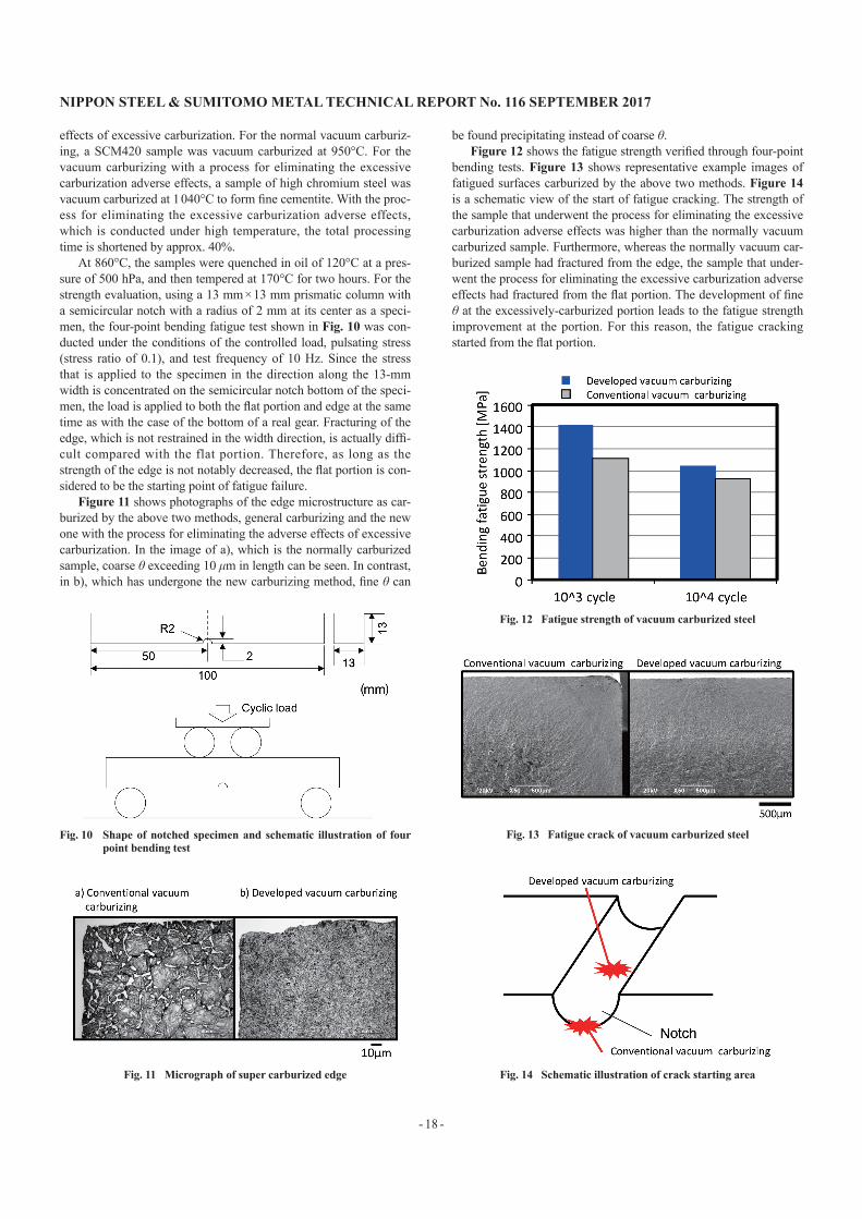
At 860°C, the samples were quenched in oil of 120°C at a pres-sure of 500 hPa, and then tempered at 170°C for two hours. For the strength evaluation, using a 13 mm × 13 mm prismatic column with a semicircular notch with a radius of 2 mm at its center as a speci-men, the four-point bending fatigue test shown in Fig. 10 was con-ducted under the conditions of the controlled load, pulsating stress (stress ratio of 0.1), and test frequency of 10 Hz. Since the stress that is applied to the specimen in the direction along the 13-mm width is concentrated on the semicircular notch bottom of the speci-men, the load is applied to both the flat portion and edge at the same time as with the case of the bottom of a real gear. Fracturing of the edge, which is not restrained in the width direction, is actually diffi-cult compared with the flat portion. Therefore, as long as the strength of the edge is not notably decreased, the flat portion is con-sidered to be the starting point of fatigue failure.
Figure 11 shows photographs of the edge microstructure as car-burized by the above two methods, general carburizing and the new one with the process for eliminating the adverse effects of excessive carburization. In the image of a), which is the normally carburized sample, coarse θ exceeding 10 μm in length can be seen. In contrast, in b), which has undergone the new carburizing method, fine θ can
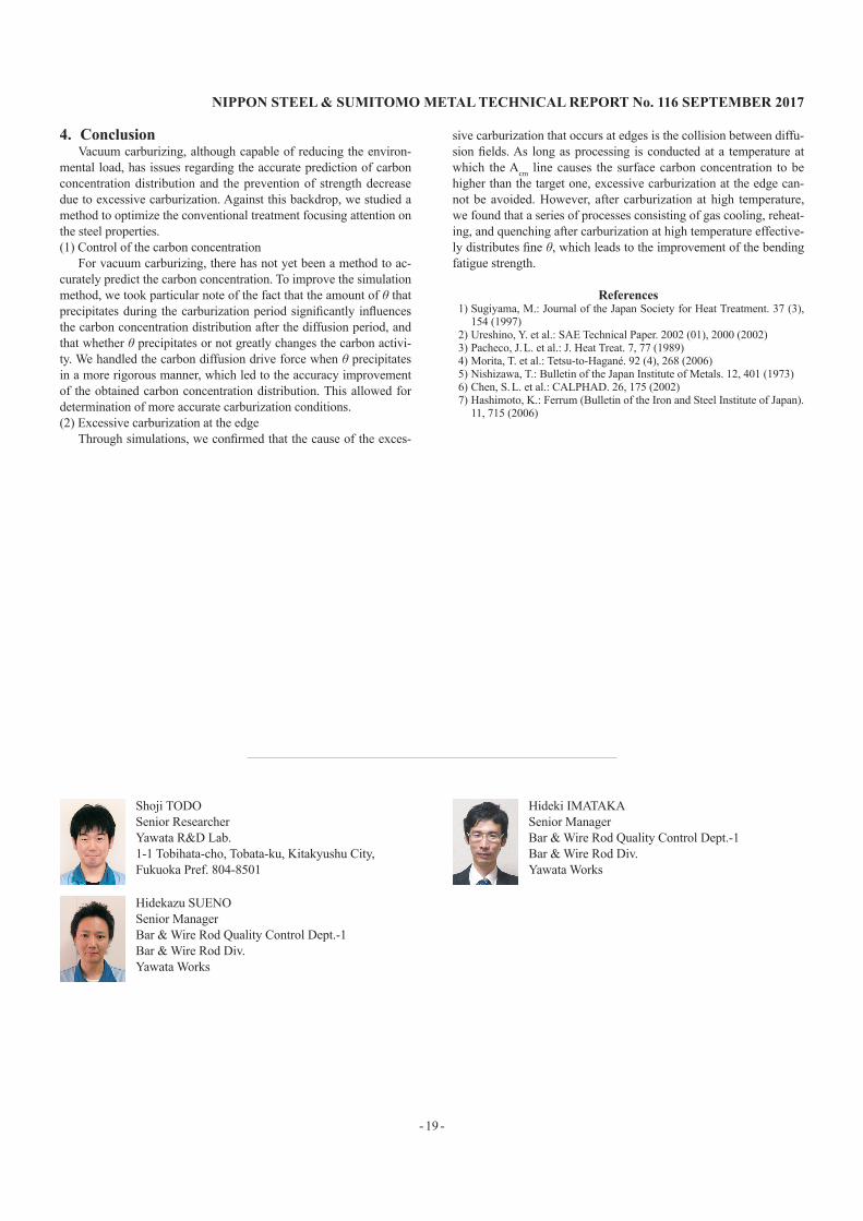
be found precipitating instead of coarse θ.Figure 12 shows the fatigue strength verified through four-point
bending tests. Figure 13 shows representative example images of fatigued surfaces carburized by the above two methods. Figure 14 is a schematic view of the start of fatigue cracking. The strength of the sample that underwent the process for eliminating the excessive carburization adverse effects was higher than the normally vacuum carburized sample. Furthermore, whereas the normally vacuum car-burized sample had fractured from the edge, the sample that under-went the process for eliminating the excessive carburization adverse effects had fractured from the flat portion. The development of fine θ at the excessively-carburized portion leads to the fatigue strength improvement at the portion. For this reason, the fatigue cracking started from the flat portion.
Fig. 10 Shape of notched specimen and schematic illustration of four point bending test
Fig. 11 Micrograph of super carburized edge
Fig. 12 Fatigue strength of vacuum carburized steel
Fig. 13 Fatigue crack of vacuum carburized steel
Fig. 14 Schematic illustration of crack starting area
NIPPON STEEL & SUMITOMO METAL TECHNICAL REPORT No. 116 SEPTEMbER 2017
- 19 -
4. ConclusionVacuum carburizing, although capable of reducing the environ-
mental load, has issues regarding the accurate prediction of carbon concentration distribution and the prevention of strength decrease due to excessive carburization. Against this backdrop, we studied a method to optimize the conventional treatment focusing attention on the steel properties.(1) Control of the carbon concentration
For vacuum carburizing, there has not yet been a method to ac-curately predict the carbon concentration. To improve the simulation method, we took particular note of the fact that the amount of θ that precipitates during the carburization period significantly influences the carbon concentration distribution after the diffusion period, and that whether θ precipitates or not greatly changes the carbon activi-ty. We handled the carbon diffusion drive force when θ precipitates in a more rigorous manner, which led to the accuracy improvement of the obtained carbon concentration distribution. This allowed for determination of more accurate carburization conditions.(2) Excessive carburization at the edge
Through simulations, we confirmed that the cause of the exces-
sive carburization that occurs at edges is the collision between diffu-sion fields. As long as processing is conducted at a temperature at which the Acm line causes the surface carbon concentration to be higher than the target one, excessive carburization at the edge can-not be avoided. However, after carburization at high temperature, we found that a series of processes consisting of gas cooling, reheat-ing, and quenching after carburization at high temperature effective-ly distributes fine θ, which leads to the improvement of the bending fatigue strength.
References1) Sugiyama, M.: Journal of the Japan Society for Heat Treatment. 37 (3),
154 (1997)2) Ureshino, Y. et al.: SAE Technical Paper. 2002 (01), 2000 (2002)3) Pacheco, J. L. et al.: J. Heat Treat. 7, 77 (1989)4) Morita, T. et al.: Tetsu-to-Hagané. 92 (4), 268 (2006)5) Nishizawa, T.: Bulletin of the Japan Institute of Metals. 12, 401 (1973)6) Chen, S. L. et al.: CALPHAD. 26, 175 (2002)7) Hashimoto, K.: Ferrum (Bulletin of the Iron and Steel Institute of Japan).
11, 715 (2006)
Shoji TODOSenior ResearcherYawata R&D Lab.1-1 Tobihata-cho, Tobata-ku, Kitakyushu City, Fukuoka Pref. 804-8501
Hideki IMATAKASenior ManagerBar & Wire Rod Quality Control Dept.-1Bar & Wire Rod Div.Yawata Works
Hidekazu SUENOSenior ManagerBar & Wire Rod Quality Control Dept.-1Bar & Wire Rod Div.Yawata Works