technical report cargo movement operations system … · cargo movement operations system (cmos)...
TRANSCRIPT

AD-A257 964
TECHNICAL REPORT
For The
Cargo Movement Operations System (CMOS)
CMOS Computer Resources LifeCycle Management Plan (Draft)
DTICELECTE
S NOV251992 30 November
1992
APrepared under
Contract Number F11624-88-D-0001/6K12 LA .,
CDRL #A004-154
Prepared for ME.
Standard Systems Center (SSC) NDeputy Chief of Staff for Logistics i3
Cargo Movement Operations System DivisionMaxwell AFB - Gunter Annex, AL 36114
ThsdCura11ri: h1Qg been approvedfor public rale4S9 and ,•le; its|d25tflI~u|jjof is uuJhnijted.
SPrepared by
Science Applications International Corporation (SAIC)5 Eagle Center, Suite 2
O'Fallon, IL 62269
(• s •••, . - . , T•"

Table of Contents
Pace
Section IIntroduction iiSummary iiConclusion ii
Section IIResults
Acce6ion For
NTIS CR-A&iDTIC TAf3UW&II-ou;ct-d [
S J tiicatio ........................
Dis IUtion lAvadebility (C~
Distr
A -,(___,
I&

SECTION I.
INTRODUCTION.
The purpose of this Technical Report is to provide theDraft Computer Resources Life Cycle Manangement Plan(CRLCMP). The results are provided in the form of theattached CRLCMP as requested by the CMOS Program Office.
SUMMARY. Not Used.
CONCLUSION. Not Used.
11
SECTION II.
RESULTS.
Our input is presented in the attached draft report.
iii

DRAFT COMPUTER RESOURCES
LIFE CYCLE MANAGEMENT PLAN
30 NOVEMBER 1992
Prepared Under
Contract Number F11624-88-D-0001/SK12
CDRL #A004-154
Prepared for
Standard Systems Center (SSC)Deputy Chief of Staff for Logistics
Cargo Movement Operations System DivisionMaxwell AFB Gunter Annex, AL 36114
Prepared by
Science Applications International Corporation (SAIC)5 Eagle Center, Suite 2
O'Fallon, IL 62269
Table of Contents
1. Introduction ............................................................................................................... Ia. Overview ............................................................................................................ 1o. Scope and Applicability ................................................................................................ Ic. References .......................................................................................................... 1
2. System Concepts ......................................................................................................... 4a. Operational Concept ............................................................................................... 4b. Support Concepts ........................................................................................................ 6
3. System Description ...................................................................................................... 7a. Overview ............................................................................................................ 7b. Com puter Hardware ............................................................................................... 7c. Com puter Software .................................................................................................. 8
4. Com puter Resource Design ........................................................................................ 9a. System Architecture and Integration ....................................................................... 9b. Product Im provements ............................................................................................. 9c. Software Development Tools and Environm ent ...................................................... 9d. Reusability ................................................................................................................. 12e. Interoperability ...................................................................................................... 12f. Additional Design Constraints ................................................................................ 12
5. Organizational Roles, Responsibilities, and Relationships ........................................... 13
8. Resources ...................................................................................................................... 14a. Personnel .................................................................................................................. 14b. Facilities .................................................................................................................... 14c. Training ..................................................................................................................... 14d. Hardware ................................................................................................................... 14e. Software .................................................................................................................... 14f. Integrated Logistics Support ................................................................................. 21
7. Docum entation ........................................................................................................... 22a. Types of Documents ............................................................................................. 22b. Data Rights ........................................................................................................... 22c. Data Managem ent ................................................................................................. 23
i
Table of Contents
8. Acquisition Managem ent Practices ............................................................................ 25a. Software Developm ent Strategy ........................................................................... 25b. Boards and Com m ittees ........................................................................................ 25c. Configuration Management ................................................................................... 27d. Docum entation Review or Approval ....................................................................... 27e. Reviews and Audits ............................................................................................... 27f. Test and Evaluation ............................................................................................... 28
g. Software Quality ................................................................................................... 29h. Security ..................................................................................................................... 29
9. Transition Managem ent Practices .............................................................................. 30a. Configuration Managem ent ................................................................................... 30b. Turnover .................................................................................................................... 30c. Support During Transition ..................................................................................... 30d. Transfer ..................................................................................................................... 30
10. Deploym ent Managem ent Practices ........................................................................... 31a. Boards and Com m ittees ........................................................................................ 31b. Configuration Management ................................................................................... 31c. Security ..................................................................................................................... 32d. Training ..................................................................................................................... 32
11. Schedules ....................................................................................................................... 33a. Major M ilestones .................................................................................................... 33b. Contract Deliverable Schedule ............................................................................... 33c. Support Capabilities ............................................................................................... 33
12. Appendices ..................................................................................................................... 36A. Acronym s and Abbreviations .............................................................................. A-1B. Glossary of Term s ............................................................................................ B-1C. List of Key Personnel .......................................................................................... C-1D. Com puter Resources W orking Group Charter .................................................... D-1E. Risk Managem ent Plan ..................................................................................... E-1F. Detailed System Description .............................................................................. F-iG . Security Assistance ............................................................................................ G-1
ii

List of Figures and Tables
2-1 CM OS Environm ent ............................................................................................ 5
4-1 CM O S Architecture .............................................................................................. 10
6-1 CMOS Unit Manpower Document (UMD) Summary ............................................. 15
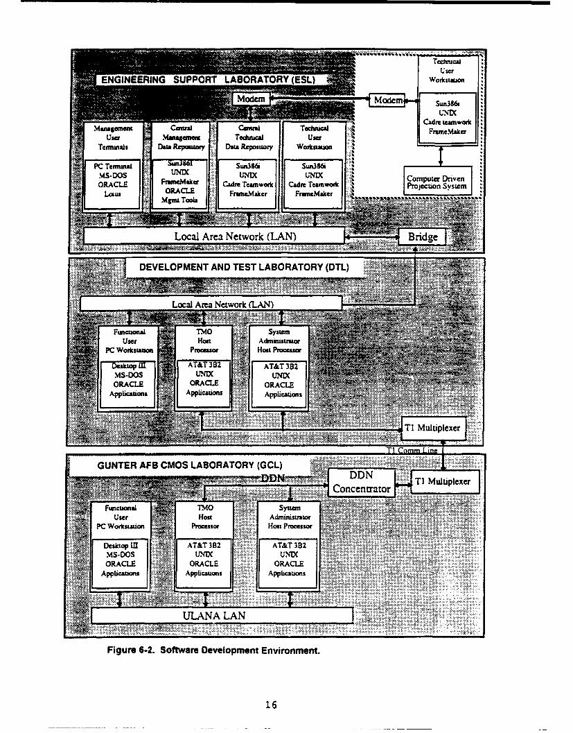
6-2 Software Developm ent Environm ent .................................................................. 16
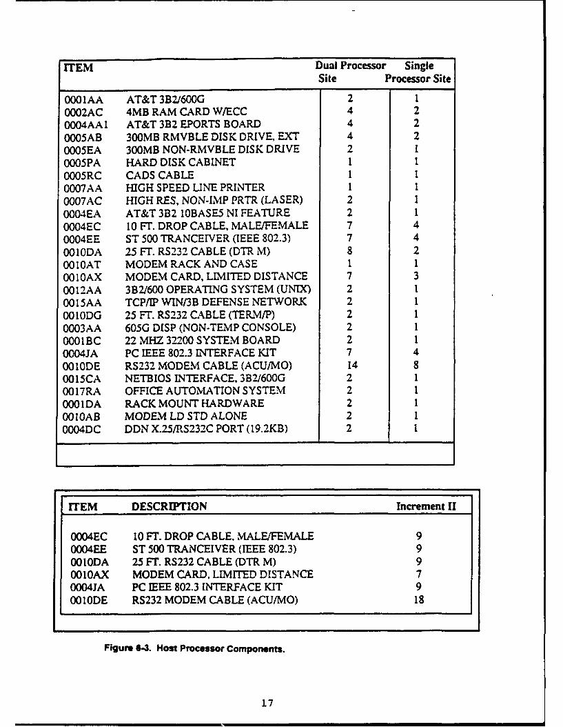
6-3 Host Processor Com ponents .............................................................................. 17
6-4 PC W orkstation Com ponents ............................................................................... 18
6-5 ULANA Com ponents ........................................................................................... 19
6-6 LOG MARS Com ponents ...................................................................................... 20
8-1 CM OS Life Cycle................................................................................................ 26
11-1 CM O S M ajor M ilestones ...................................................................................... 34
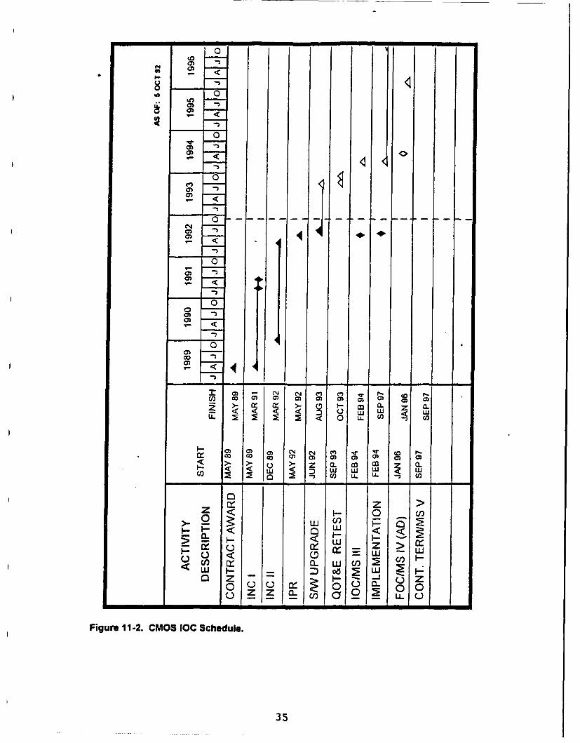
11-2 CM O S IOC Schedule ........................................................................................... 35
iii

CMOS Computer Resources Life CycleManagement Plan (CRLCMP)
1. Introduction.
a. Overview. The CMOS Computer Resources Ufe Cycle Management Plan (CRLCMP)serves as the life cycle management document for the development of the Air Force CargoMovement Operations System (CMOS). CMOS is an Air Force standard informationsystem which provides automated data processing (ADP) support to the Air Force'stransportation community. The primary goals of the CRLCMP are to:
(1) Document the computer resources development strategy, the philosophy forlife cycle management, and the methodology for development of computerresources;
(2) Document the software support concept and the resources needed to achievethat support posture;
(3) Identify the applicable directives (regulations, operating instructions, technicalorders, etc.) for managing computer resources in the CMOS system; and
(4) Define any changes or new directives needed for operation or support ofcomputer resources in CMOS.
b. Scope and Applicability. The CRLCMP is created and updE' ed under the direction ofthe United States Air Force in response to HO USAF Program Management Directive(PMD) 5272(4)/ PE #3861 OF, dated 5 December 1986, as revised 5 June 1992. The PMDdirects the development of an automated system to support regular and crisis cargo andpers~uiAel processing, documentation, movement and tracking for the base-levelTransportation Management Office (TMO).
CMOS has requirements for a two-way data interface with the Standard Base SupplySystem (SBSS), the Consolidated Aerial Port System (CAPS II), the Stock Control andDistribution System (SC&D), the Air Force Consolidation Containerization Point System(CCP), the Base-Level Transportation Workload Reporting and Productivity System (B-"TWRAPS), the Headquarters On-line System for Transportation (HOST), the ComputerAided Load Manifesting (CALM) system, the Department of the Army MovementManagement System - Redesign (DAMMS-R), the Terminal Management System/WaterClearance Authority system (TERMS/WCA), and the Air Clearance Authority (ACA) system.
CMOS also has requirements to send data to the Air Force Command and Control System(AFC2S), the Central Data Collection Point (CDCP) system, and the EnhancedTransportation Automated Data System (ETADS), and to receive data from the CombatAmmunition System - Base level (CAS-B), and the Contingency Operations MobilityPlanning and Execution System - Base level (COMPES-B).
c. References.
(1) Requirements Documents.
CMOS Operational Requirements Document (ORD) (Draft Final), 28 September1992.Information Systems Requirements Document (ISRD) - CMOS. 18 April 1986.
1

(2) Directives.
CMOS Program Management Directive (PMD) 5272(1)/ PE #3861 OF, 5 December1986, as revised 19 December 1991.
(3) Regulations.
DODR 4500.32 Military Standard Transportation and Movement Procedures(MILSTAMP).AFR 14-1, "Configuration Management", December 1988.AFR 4-29, "Air Force Data Management and Standards Program", April 1990.AFR 28-4, "USAF Mobility Planning", 27 March 1987.AFR 71-4, "Preparing Hazardous Materials for Military Air Shipment".AFR 71-9, "Air Force Packaging".AFR 75-1, "Transportation of Material".AFR 75-2, "Defense Transportation Management Regulation".AFR 80-14, "Test and Evaluation", November 1986.AFR 205-16, "Automated Data Processing Security Policy, Procedures, andRegulations".AFR 310-1, "Management of Contractor Data", March 1983.AFR 700-10, "Information Systems Securityo, March 1985.AFR 800-14, "Life Cycle Management of Computer Resources in Systems",September 1986.
(4) Standards.
DOD 5200.28-STD, "Trusted Computer System Evaluation Criteria", December 1985DOD-STD-2167A, "Defense System Software Development", February 1988.DOD-STD-2168, "Defense System Quality Program".MIL-STD-480B, "Configuration Control Engineering Changes, Deviations andWaivers", July 1988.MIL-STD-483A, "Configuration Management Practices for Systems, Equipment,Munitions, and Computer Programs", June 1985.MIL-STD-490A, "Specification Practices", June 1985.MIL-STD-1 521 B, Notice 1, "Technical Reviews and Audits for Systems, Equipment,and Computer Programs", December 1985.
(5) Plans.
CMOS Communications-Computer Systems Program Plan (CSPP), 1 September1987.CMOS Test and Evaluation Master Plan (TEMP) for Increment I, 19 December 1991.CMOS Integrated Logistics Support Plan (ILSP), undated.
(6) Other Documents.
CMOS System Concept, 24 August 1987.CMOS Increment I Contract Number GS-OOK-89-AJD01 11.Updated Final (Change 03), System/Segment Specification (SSS), Increment II, 13December 1991.Revised Final (Change 02) System/Segment Design Document (SSDD), 13December 1990.Revised Final (Change 01) Requirements Traceability Matrix (RTM), 23 December
2

1991.
Updated Final Software Requirements Specification (SRS) for the ApplicationsComputer Software Configuration Item (CSCI), 22 February 1991.Updated Final SRS for the Communications CSCI, 18 January 1991.Final SRS for the System Environment CSCI, 14 December 1990.Updated Final Interface Requirements Specification (IRS), 22 March 1991.Interface Design Document (IDD), Version 2.3.0, 4 September 1992.Software Design Document (SDD) for the Applications CSCI, Version 2.3.0. 4September 1992.SDD for the Communications CSC , Version 2.3.0, 4 September 1992.CMOS Monthly Program Status Report, (latest version).

2. System Concepts.
a. Operational Concept. CMOS will support the peacetime and wartime activities of anAir Force base TMO associated with the movement of cargo by any mode, and passengerson military aircraft. CMOS will provide the capability to effectively plan, document, andmanage outbound and inbound movements. The system will accumulate and aggregatemovement requirements data provided by electronic interface or manual entry; track thecompletion of transportation actions; prepare, print, and transmit movement documentationto notify en route and destination sites of the movement; and track receipt and distributionactivities. The CMOS operational environment is described in the following paragraphs:
(1) CMOS will operate at Air Force active duty, Air Force Reserve, and Air NationalGuard sites around the world (approximately 203 sites in total). CMOS will be usedprimarily by TMO personnel. The CMOS configuration depicted in Figure 2-1provides a representation of the physical environment at most active duty sites, asestablished by Increment I of CMOS, and the expansion provided in Increment II tosupport mobility processing. The expansion includes adding the LogisticsApplications of Automated Marking and Reading Symbols (LOGMARS) capability andadditional Personal Computer (PC) workstations. A total of 15 PC workstations mayeither be directly connected to the CMOS Local Area Network (LAN) or connectedthrough a Multipoint Attachment Unit (MAU), to be used at the discretion of the TMOto meet workload demands. PC workstations will be moved as required from theirpeacetime locations to support mobility operations.
(2) The CMOS operational environment will be supported by hardware and softwarefrom the Standard Multi-user Small Computer Requirements Contract (SMSCRC),Desktop Iil, Unified Local Area Network Architecture (ULANA), and LOGMARScontracts. Components from these contracts will be integrated with non-developmental software (NDS), or contractor-developed software.
(3) At all active duty, Air National Guard, and Air Force Reserve sites, one AT&T3B2/600GR minicomputer from the SMSCRC contract will be used as the TMO host.All host processor units will be connected to Uninterruptible Power Supply (UPS)devices.
(4) The Desktop III microcomputer will be used as the hardware platform for the userinterface in each of the functional areas. The MS-DOS operating system will be usedto support an ORACLE data base interface to the central processor. The Packing andCrating, Air Freight, Surface Freight, Air Cargo Terminal, and Transportation ControlUnit stations will have both laser and dot matrix printers attached. The remainingstations will have only a dot matrix printer.
(5) Components from the ULANA contract will be used to provide thecommunications path between the host processors and the PC workstations, primarihyvia an 802.3 compliant Ethemet LAN. The LAN will also be used to access theDefense Data Network (DDN) to provide long-haul communications for CMOS. Bothprocessors will have DDN interface capability, although only one line will be providedto the nearest DDN Concentrator. The line will be switched to the backup processorin the event of failure in the TMO host at sites with two host processors.
(6) CMOS will also use Automatic Digital Network (AUTODIN) in the event of DDNfailure, and to interface with those systems whik.i are not yet DON-capable. Diskettetransfer will be accomplished using the Automated Data Reports Submission System
4

Packing & Crating Shipment Planning
DDN/X.25
System Administrator
I0I
Figure~~as StatCOSEnirnmnt
Mobii~y ontrl LOMA5

(ADRSS) and Base Level AUTODIN Message Extraction System (BLAMES)software.
(7) Transfer of data between CMOS and SBSS will be accomplished using theInteractive Communications Interface (ICI) protocols.
(8) CALM software will be present on those stations that need to do aircraft loadplanning. Data will be exchanged between CMOS and CALM via the CMOS centraldata base.
(9) LOGMARS bar code scanning devices will be used for rapid and accuratecollection of transportation and shipment data. The LOGMARS Hand Held Terminal(HHT) will be used to update, retrieve, or display data contained within the CMOSdata base. Communications between the HHT and the CMOS data base will beeither through an RF base station connected through a PC workstation to the CMOSLAN or via cabling directly to any PC workstation on the LAN.
(10) The primary uses of NDS will be to support the central data base and to provideElectronic Data Interchange (EDI)-formatted communications. Specifically, theORACLE data base, and its associated suite of Structured Query Language (SQL)and support facilities will form the core of the CMOS software. EDI software will allowCMOS users to extract, package, and manage messages to and from EDI tradingpartners using Transaction Set 858.
(11) Electronic mail will be used to notify the user of MICAP/999 or priority I and 2messages received by the system. Each CMOS user will have the capability toaccess any of the available functional areas.
(12) There are numerous existing and proposed interfaces to external systems.Changes to these systems will require revisions to the CMOS system functions whichmanage inbound and outbound data transfers.
b. Support Concepts. The CMOS hardware will be purchased from the standardcontracts listed in the preceding paragraph. The hardware will be serviced through amaintenance option from a standard contract or from local maintenance arrangements.Establishment of repair versus replacement criteria is, and will remain, the responsibility ofthe CMOS SPO. The Integrated Logistics Support Plan (ILSP) makes specificrecommendations on repair versus replacement procedures. Logistics support is theresponsibility of the CMOS SPO and should be included in the equipment maintenancecontract. All expendable supplies will be purchased from standard Air Force contracts. Thesoftware support concept is of Type "E" (from AFR 800-14, attachment 8), since Air ForceMateriel Command (AFMC) (formerly Air Force Logistics Command (AFLC)) is notresponsible for any phase of the software support function.
6

3. System Description.
a. Overview. The CMOS Increment I software automates the standard functions of thebase-level TMO, i.e., packing and crating, shipment planning, and the air freight andsurface freight work centers. The CMOS system will allow the transportation activity toautomate all of its functions in order to effectively support the variety of missions with whichit is tasked. Increment II functions will automate transportation's support of installation-levelmobility activities, including deployment, reception, and redeployment of combat forces.Interfaces with additional automated systems beyond those found in Increment I softwareare also implemented.
The CMOS architecture is composed of four Hardware Configuration Items (HWCIs) andthree Computer Software Configuration Items (CSCIs). The functions performed by theLocal Area Network, Host Processor, PC Workstation and LOGMARS HWCls are describedin paragraph b. below. Paragraph c. describes the functions of the CMOS Applications,Communications, and System Environment CSCis.
b. Computer Hardware. Detailed listings of HWCI components may be found in Tables6-3 through 6-10.
(1) The LAN HWCI will provide the communication path between the Host ProcessorsHWCI components and the PC Workstation HWCI components. The LAN will facilitate thetransfer of CMOS functional data, user mail, and other system data throughout the localCMOS system. The LAN will allow the various CMOS users to process cargo in a timelymanner and to inform other CMOS users of cargo movements, both on site and outside thelocal CMOS community.
The LAN will be implemented using ULANA components. The LAN requires Institute ofElectrical and Electronics Engineers (IEEE) 802.3 compatible LAN cards, coaxial cable, anda cable-attached transceiver.
(2) The Host Processor HWCI includes the TMO minicomputer, as well as supporthardware such as printers and UPS equipment. The host processor will provide theexternal communications functions, maintenance and control of the central integrated database, control of the LAN, and restart and recovery functions.
The SMSCRC will provide one AT&T 3B2/600GR minicomputer, currently configured with32 Megabytes (Mb) of RAM, a 300 Mb system disk and two 300 Mb data base disks. A 120Mb streaming tape drive will be used for system backup and will support the requirement fordata base integrity. An eight-millimeter cartridge-tape backup unit is also available. Forlarge volume reports, the host processors will share an 800 line per minute printer. UPSunits will provide 10 minutes of operability to allow a controlled shutdown of the data base.
System external interfaces will either be through an X.25 connection to the local DDNconcentrator, or via diskette into AUTODIN.
(3) The PC Workstation HWCI includes the PC itself and directly connected printers. ThePC workstations will provide the functionality needed by the Shipment Planning, Packingand Crating, Surface Freight, Air Freight, Outside the Continental United States (OCONUS)ACA, Air Cargo Terminal, Air Passenger Terminal, Mobility Control Unit, TransportationPlans and Programs, Load Planning, Transportation Control Unit and CAS-B work centersto process, document, and report cargo movement. PC workstations will be relocated fromtheir normal peacetime locations and placed in the work centers required to support mobilityoperations.
7

The Desktop III microcomputer will be used as the standard PC Workstation, configuredwith 4 Mb of Random Access Memory (RAM), and 84 Mb hard drive, one 3.5" 1.44Mbfloppy drive, one 5.25" 360 kilobyte floppy drive, and a Video Graphics Array (VGA) colormonitor. An Ethernet card will be installed to allow connectivity to the CMOS LAN. Somefunctional areas will have both a laser printer and a dot matrix printer, while others will haveonly the dot matrix printer.
(4) The LOGMARS HWCI includes the LOGMARS HHT and scanner. The LOGMARSequipment will be used for rapid and accurate transaction input into the data base, and willbe the main input device for tracking cargo movements throughout the TMO facility. TheHHT will interface with the PC Workstation through a communications dock connectedthrough an RS-232 port.
The INTERMEC Trakker 9440 Portable Transaction Manager, the INTERMEC Model 1500Laser Scanner, and the INTERMEC Trakker 40D Communications Dock will be theLOGMARS equipment used.
c. Computer Software. A reference for detailed descriptions of each of the CSCIs maybe found in Appendix F.
(1) The CMOS Applications CSCI provides access to, and execution of, all userapplications. Functions supported include System Administration, Process OutboundCargo, Process inbound Cargo, User Services, Perform Air Passenger Function,Transportation Plans and Programs, and Command and Control Operations.
(2) The Communications CSCI provides all direct communication support for both internaland external communications. Functions provided include the DDN Adapter, AUTODINAdapter, LAN Adapter, Mail Adapter, ICI Adapter, Incoming Message Manager, andOutgoing Message Manager.
(3) The System Environment CSCI provides Non-Developmental Software (NDS) supportto the other CSCIs. System Environment software on the Host Processor HWCI equipmentincludes the Host Processor OS, TCP/IP WIN/3B software, Office Automation System, HighOrder Language Interface, Relational Data Base Management System (RDBMS) for theHost, ICI Interface, and EDI software. System Environment software found on the PCWorkstation HWCI equipment includes the PC Workstation OS, Net BIOS Interface, VideoDrivers software, High Order Language Interface, RDBMS for the PC, LAN PC Interface,Windows software, CALM software, Graphics Software System (GSS) Drivers, ForeignLanguage Laser Fonts, and OCR Laser Fonts. System environment software resident onthe LOGMARS HWCI equipment includes the LOGMARS software.
8
4. Computer Resource Design.
a. System Architecture and Integration. There are four HWCIs and three CSCIs in theCMOS architecture, as described in paragraph 3 of this document. Refer to Figure 4-1 for ahigh-level view of how these components are integrated.
CMOS is not an embedded system, and does not have the built-in-test and fault-tolerancefunctions associated with these types of systems, nor does it have maintenance interfacesor special test equipment, except those used by contract maintenance technicians servicingCMOS hardware.
Since CMOS uses non militarized general purpose commercially available hardware, therequirements of MIL-STD-1750, "Instruction Set Architecture", and MIL-STD-1553,"Standard Bus Architecture", do not apply, as per AFR 800-14, paragraph 3-10 a. A waiverto the requirement for use of Ada as the High Order Language has been approved on thegrounds that the C programming language is more fully supported as an interface to theORACLE RDBMS.
The CMOS software has been divided into three CSCIs: CMOS Applications,Communications, and Systems Environment. "Mission" software, as defined in Attachment7 of AFR 800-14, has been grouped into the CMOS Applications CSCI. Both theCommunications and Systems Environment CSCIs are composed of "support" software,also as defined in Attachment 7 of AFR 800-14.
All CMOS hardware, and all System Environment CSCI software, is Commercial Off TheShelf (COTS) equipment purchased from standard government contracts.
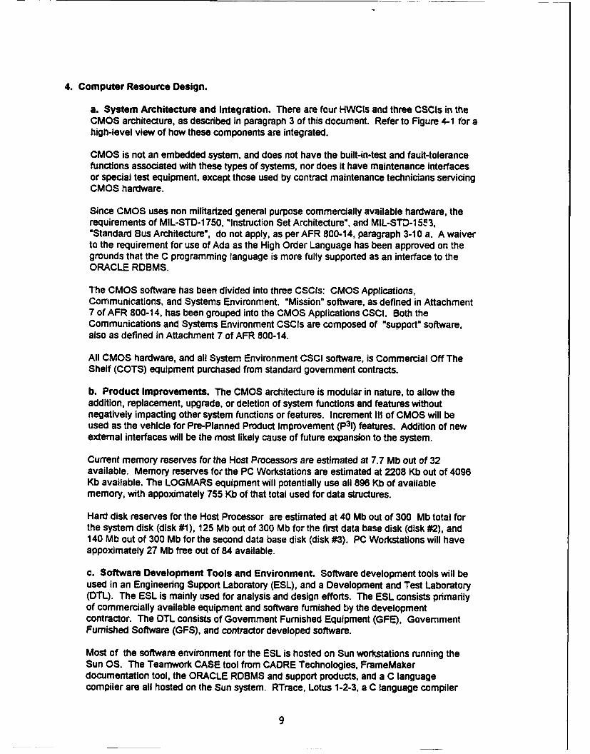
b. Product Improvements. The CMOS architecture is modular in nature, to allow theaddition, replacement, upgrade, or deletion of system functions and features withoutnegatively impacting other system functions or features. Increment III of CMOS will beused as the vehicle for Pre-Planned Product Improvement (p31) features. Addition of newexternal interfaces will be the most likely cause of future expansion to the system.
Current memory reserves for the Host Processors are estimated at 7.7 Mb out of 32available. Memory reserves for the PC Workstations are estimated at 2208 Kb out of 4096Kb available. The LOGMARS equipment will potentially use all 896 Kb of availablememory, with appoximately 755 Kb of that total used for data structures.
Hard disk reserves for the Host Processor are estimated at 40 Mb out of 300 Mb total forthe system disk (disk #1), 125 Mb out of 300 Mb for the first data base disk (disk #2), and140 Mb out of 300 Mb for the second data base disk (disk #3). PC Workstations will haveappoximately 27 Mb free out of 84 available.
c. Software Development Tools and Environment. Software development tools will beused in an Engineering Support Laboratory (ESL), and a Development and Test Laboratory(DTL). The ESL is mainly used for analysis and design efforts. The ESL consists primarilyof commercially available equipment and software furnished by the developmentcontractor. The DTL consists of Government Furnished Equipment (GFE), GovernmentFurnished Software (GFS), and contractor developed software.
Most of the software environment for the ESL is hosted on Sun workstations running theSun OS. The Teamwork CASE tool from CADRE Technologies, FrameMakerdocumentation tool, the ORACLE RDBMS and support products, and a C languagecompiler are all hosted on the Sun system. RTrace, Lotus 1-2-3, a C language compiler
9

CM~s CM~s O CMUNCAOS,
USERS APPICATIANSS
100

and an adaptation of the Unix Source Code Control System (SCCS) are hosted on a PCworkstation. MacDraw II and MacProject are hosted on an Apple Macintosh.
Teamwork has several modules and applications. Teamwork SA is designed to aid analystsin building, storing, reviewing, maintaining structured reviews, and maintaining DOD-STD-2167A specifications. It handles data flow diagrams, process specifications, and datadefinitions. It provides consistency checking query functions and total integration to otherobjects in the data base. Teamwork RT uses decision tables, data control flow, and statetransition diagrams to perform real-time modeling of specifications. It provides consistencychecking, query functions, and total integration to other objects in the data base (entities,attributes, etc.). Teamwork IM captures entities, relationships, and attributes in the datadictionary for development of Entity-Relationship Diagrams. A consistency checkerprovides a schema generator to the ORACLE Data Design Language (DDL), relationnormalizer, and total integration and interface to other data base objects (data flows, datastores, etc.). Teamwork SD supports structured design methodology and standard notation.It graphically represents the object of design (modules, invocations, couples, andconnectors). Design rule checking is provided for completeness and validity based on thesoftware design standards.
The ORACLE RDBMS capabilities include multi-user support, a data dictionary, queryoptimization, distributed queries, and extensive numeric, text and logical functions. Severalsupport products will be used in conjunction with the ORACLE RDBMS. SQL*Plus is theSQL 4th generation language interface to the ORACLE RDBMS for querying, report writing,and data transferring. SQL*Net allows networking the ORACLE environment. SQL*Formsis a 4th generation tool enabling the user to build forms-based applications and prototypesusing a screen painter. SQL*Report formats the results of queries into a report. The reportcan be formatted by specifying page size, numbering, headers, footers, titles, and fieldlengths. The data is selected from the data base using SQL*Plus statements. Pro*C is apre compiler that converts a "C" source program that includes SQL statements into anexecutable program that can be used to access and manipulate data in an ORACLE database. SQL*Menu allows design of custom menu-driven interfaces to ORACLE applications.Data base Add-in for Lotus 1-2-3 provides an interface between Lotus 1-2-3 and ORACLE.SQL*Graph allows graphic representations of numerical data that resides in the ORACLEdata base to be produced.
FrameMaker is the document publishing system used to create finished deliverables.Output from Teamwork, MacPaint, and MacDraw can be loaded into FrameMaker toproduce high-quality deliverables.
The native C compiler provided with Unix operating systems will be used to generateprograms for communications interfaces and complex algorithms. A Microsoft C compilerwill be used to generate C code on the PC workstations.
RTrace provides the initial step necessary for tracking and managing all requirements. Allrequirements to the Computer Software Unit (CSU) level are electronically parsed byRTrace, reducing potential errors and saving time. These requirements can then beorganized, edited, allocated, traced, and reported.
The Lotus 1-2-3 spreadsheet program is interfaced with the ORACLE RDBMS through theAdd-In Manager function to facilitate affinity analysis.
MacDraw and MacPaint are used to produce diagrams and pictures needed to enhancedocumentation.
11

MacProject provides the project planning and charting tools to plan tasks, milestones, andevents.
d. Reusability. The Government and development contractor will use the automatedcapability of the CMOS software development environment to capture the requirementsanalysis, database, and software design information produced during the design of theCMOS system. This will facilitate the reuse of the software modules, data and informationgathered during subsequent automation of transportation systems.
e. Interoperability. Within CMOS, access to any function shall be available from anyworkstation. Access to these functions shall be controlled through the use of passwordprotection, not location. In addition, any PC Workstation hardware shall be interchangeablewith any other PC Workstation, provided that necessary resident data has been uploadedbefore the interchange takes place. Interoperability with systems external to CMOS will befacilitated by use of hardware and software purchased from government standard contractswherever possible. In addition, use of the DON and AUTODIN networks to communicatewith external systems relieves CMOS of the responsibility of negotiating unique datatransfer 'nrotocols.
f. Additional Design Constraints. In general, the mandated use of GFE and COTSsoftware from the SMSCRC, ULANA, LOGMARS, and Desktop III contracts imposesconstraints on the overall design of CMOS. In addition, there is a conflict between theCMOS software and the CALM load planning software on the PC Workstation HWCI.When the CALM software is executed, the PC is automatically rebooted by CALM. Thisaction causes conditions to occur within the PC's memory that will not allow the ORACLEsoftware to restart without resetting the PC' s memory (i.e., a warm boot of the system). Asa result, users requiring a CALM-generated load list must select data for input to loadplanning, download the data to the PC, and receive a load list from the load planningsoftware, and upload the load list to the Host Processor.
12

5. Organizational Roles, Responsibilities, and Relationships. PMD 5272(4)/PE #38610F,designates Air Force Communications Command (AFCC) as the implementing command for theCMOS Program. Responsibilities for the program were further delegated to the CMOS SystemProgram Office (SPO), SSC/LGTT. The CMOS SPO is responsible for contractors used todevelop the CMOS system. The SPO will contract for the analysis and development of theCMOS standard systems. The SPO will also contract for Independent Verification and Validation(IV&V) efforts and technical support services (to include technical evaluations, requirementsanalysis, cost management, and other support of the mission as required). Organizational roles,responsibilities, and relationships of the Implementing Command, Supporting Commands,Operating Commands, Participating Commands, and Other Agencies/Offices are detailed in thePMD.
13

6. Resources:
a. Personnel. Air Force personnel requirements are detailed in Figure 6-1.
b. Facilities. The CMOS SPO will maintain a laboratory with the most current hardwareand software configuration. This facility will be connected to the ESL and the Developmentand Test Laboratory (DTL) maintained by the development contractor via a T-1communications link. See Figure 6-2 for a representation of the facilities to be used indeveloping, testing, and supporting CMOS computer resources.
c. Training. No special training is to be provided by the government in support ofdeveloping, testing and supporting the computer resources.
d. Hardware. CMOS hardware will be provided from standard computer acquisitioncontracts such as the SMSCRC, the Desktop III Small Computer Contract, the ULANAContract, and the LOG MARS Contract. A description of the items needed to supportCMOS is provided in Figures 8-3 through 6-6. In addition, the development contractor willuse Sun workstations and Macintosh personal computers to support the development ofCMOS, as described in paragraph 4.c.
e. Software. CMOS will use the following software development tools:
1. DOS Version 5.0 - used for all CMOS DOS batch processing to accomplish a varietyof tasks. These processes will execute in background mode.
2. Unix System V Shell Scripts - used on the Host processors to accomplish a variety oftasks. These processes will execute in background mode.
3. ORACLE SQL*PIus Scripts - used to perform a variety of tasks related to theORACLE RDBMS.
4. ORACLE SQL*Forms - used to construct user screens for CMOS.
5. ORACLE SQL*ReportWriter - used to implement CMOS requirements that call for thegeneration of reports based on CMOS data.
6. Microsoft C Version 5.1 - used to supplement the ORACLE suite of products on thePC workstation when CMOS requirements cannot be met by use of those productsalone.
7. C language compiler prov.'ed with AT&T UNIX System V - used to supplement theORACLE suite of products on the Host Processor when CMOS requirements cannotbe met by use of those products alone.
8. IRL Programming Language - used for coding the CMOS LOGMARS processes.
9. PRESCRIBE Programming Language - The PRESCRIBE programming language willbe used to provide CMOS users with system-generated forms on the CMOS Kyoceralaser printers.
14

LGTT CMOS
BY SPECIALTY TOTALS
AFSC AGR GRD06016 MAJ MAJ MANAGEMENT 1 OFFICERS 170250 CIV GS05 TECHNICAL 0 ENLISTED 0
FUNCTIONAL 0 CIVILIANS 1SUPPORT 1 TERMS 0
TOTAL AUTHORIZED 2
SUBORDINATE SUPERVISORY PERSONNEL 2
LGTTF FUNCTIONAL REQUIREMENTS
BY SPECIALTY TOTALS
AFSC AGR GRD06054 CPT CPT MANAGEMENT 3 OFFICERS 202754 CPT TECHNICAL 0 ENLISTED 306054 CIV GS12 FUNCTIONAL 6 CIVILIANS 406054 CIV GS12 SUPPORT 0 TERMS 006054 CIV GS12 TOTAL AUTHORIZED 906054 CIV GS1260299 SMS MSG60273 TSG MSG60273 TSG MSG
TOTAL PERSONNEL SUPERVISED 8
LGTTS SYSTEMS ENGINEERING
BY SPECIALTY. TOTALS
AFSC AGR GRD04925 CIV GM13 MANAGEMENT 10 OFFICERS 202724 CPT CPT TECHNICAL 6 ENLISTED 402724 MAJ CPT FUNCTIONAL 0 CIVILIANS 304925 CPT CPT SUPPORT 2 TERMS 004925 CIV GS12 CONTRACTORS 7004925 CIV GS12 TOTAL AUTHORIZED 7949152 SSG SSG70250 SSG49132 A1C AIC70250 AMN AMN
TOTAL PERSONNEL SUPERVISED 78
Figure 6-1. CMOS Unit Manpower Document (UMD) Summary.
15
ENGINEERING SUPPORT LAB
UnUNN
Cadre teamworkMatiagernmt can" CAMS1, TOCMWAI FrameMaker
Usa Morl"allent Teduucal UserTerminals Dom Reponwry Data Repository Workstation
PC Tcmunal SunJ86l Sun3g&Sur%39&
UMX.MS-DOS U1Mx UNIX Computer DrivenORACLE FameMaker Cadre Teamwork Cadre Teamwork A Projecuon System
Lotus ORACLE FnamMaker FnimeMakerMgmt Tools
Local Area Network (LAN) age-- -- ---- ....
V DEVELOPMENT AND TEST LABORATORY (DTL) WX NEW
W .................... . .......... .ALocal Area Network (LAN) .... .
Functional TMO SystemUser Host Admirusttaw
PC Workstatm Pfacess" Host Processor
Desktop M AT&T382 AT&T382MS-DOS UNIXORACLE ORACLE ORACLE N ......... ......Applications
Applications AppLications : ........... W
ýX TI Multdipl xer....... .......
TI Comm Line I
GUNTER AFS CMOS LABORATORY (GCL) V
DDN. ... .. TI MWtiplcxer2M. x
to onc ý: e :: n -t: , rator
functional TMO SystemUser Host R
PC Worksuuon =es Host Procesuw.2
sktop .0De AT&T 3 B2 AT&T382
,A-DOS UNDCMS UNDCORA ORACLE ORACLE
PpLica AppLicatrons Applications
ULANA LANW ...
Figure 6-2. Software Development Environment.
16
ITEM Dual Processor SingleSite Processor Site
00O1AA AT&T 3B2/600G 2 10002AC 4MB RAM CARD W/ECC 4 20004AA1 AT&T 3B2 EPORTS BOARD 4 20005AB 300MB RMVBLE DISK DRIVE, EXT 4 20005EA 300MB NON-RMVBLE DISK DRIVE 2 10005PA HARD DISK CABINET 1 10005RC CADS CABLE 1 10007AA HIGH SPEED LINE PRINTER 1 10007AC HIGH RES, NON-IMP PRTR (LASER) 2 10004EA AT&T 3B2 10BASE5 NI FEATURE 2 10004EC 10 FT. DROP CABLE, MALE/FEMALE 7 40004EE ST 500 TRANCEIVER (IEEE 802.3) 7 40010DA 25 FT. RS232 CABLE (DTR M) 8 20010AT MODEM RACK AND CASE 1 10010AX MODEM CARD, LIMITED DISTANCE 7 30012AA 3B2/600 OPERATING SYSTEM (UNIX) 2 10015AA TCP/IP WIN/3B DEFENSE NETWORK 2 10010DG 25 FT. RS232 CABLE (TERM/P) 2 10003AA 605G DISP (NON-TEMP CONSOLE) 2 10001BC 22 MHZ 32200 SYSTEM BOARD 2 100041A PC IEEE 802.3 INTERFACE KIT 7 40010DE RS232 MODEM CABLE (ACU/MO) 14 80015CA NETBIOS INTERFACE, 3B2/600G 2 10017RA OFFICE AUTOMATION SYSTEM 2 10001DA RACK MOUNT HARDWARE 2 10010AB MODEM LD STD ALONE 2 10004DC DDN X.25/RS232C PORT (19.2KB) 2 1
ITEM DESCRIPTION Increment II
0004EC 10 FT. DROP CABLE, MALE/FEMALE 900O4EE ST 500 TRANCEIVER (IEEE 802.3) 90010DA 25 FT. RS232 CABLE (DTR M) 90010AX MODEM CARD. LIMITED DISTANCE 70004JA PC IEEE 802.3 INTERFACE KIT 90010DE RS232 MODEM CABLE (ACU/MO) 18
Figu 64-3. Host Processor Components.
17

DESKTOP III
Dual SingleITEM DESCRIPTION Processor Processor
Site Site
0002AB ADVANCED COMPUTER SYSTEM 7 4(includes 4 MB Memory and Serial/Parallel Ports)
0003AB 14" VGA MONITOR 7 40003AE VGA VIDEO BOARD 7 40006AB INTERNAL 5.25" FLOPPY DISKETTE 7 40007AB 84 MB SCSI INTERNAL HARD DRIVE 7 4001 IAA DOT MATRIX/LQ PRINTER 7/3 4/20015AJ LAN INTERFACE CARD 7 40015AK LAN INTERFACE TRANSCEIVER 7 40015AL MS-DOS ETHERNET/NETBIOS SOFTWARE 7 40015AQ 50' TRANSCEIVER CABLE 7 40023AA MS-DOS 4.01 7 4
DESKTOP III
ITEM DESCRIPTION Increment II
0002AB ADVANCED COMPUTER SYSTEM 9(includes 4 MB Memory and Serial/Parallel Ports)
0003AB 14" VGA MONITOR 90003AE VGA VIDEO BOARD 90006AA INTERNAL 3.5" FLOPPY DISKETTE 90006AB INTERNAL 5.25" FLOPPY DISKETTE 90007AB 84 MB SCSI INTERNAL HARD DRIVE 9001 1AA DOT MATRIX/LQ PRINTER 9/20015AJ LAN INTERFACE CARD 90015AK LAN INTERFACE TRANSCEIVER 90015AL MS-DOS ETHERNET/NETBIOS SOFTWARE 90015AQ 50' TRANSCEIVER CABLE 90023AA MS-DOS 4.01 9
Figure 6-4. PC Workstation Components.
18

ULANA
Dual SingleITEM DESCRIPTION Processor Processor
Site Site
B02 HAU-IBM AT/Desktop III/DOS 3 3(or AT&T 0004AJ3)
B08 BASEBAND IOBASE5 MAU 3 3
B 14 AAU5-16 PORT (or AT&T 0004AJ3) I
B33 TRANCEIVER CABLES 3 3
ULANA
ITEM Dual Processor Single Processor
B02 HAU-IBM AT (Desktop Il/DOS) 9 5
B08 BASEBAND 1OBASE5 MAU 11 6
B14 AAU5-16 PORT I
B33 TRANSCEIVER CABLES 11 6
Figure 6-6. ULANA Components.
19

LOGMARSDual Single
ITEM DESCRIPTION Processor ProcessorSite Site
1004AA BAR-CODE SCANNER 3 21001AC PDCD TRAKKER 9400 3 31001MA NICAD BATTERY CHARGER 3 21001NA NICAD BATTERY PACK 6 41012AA PORTABLE BAR-CODE ANALYZER I1001CD PORT CONCENTRATOR 3 21010MC ASYNC-ASYNC CABLE Z-248 3 21001QB EPROM, 64KB 6 4
Figure 6-6. LOGMARS Components.
20

f. Integrated Logistics Support (ILS). An ILSP has been developed for the CMOS program.The ILSP is an Air Force management plan developed and used to manage the ILS process.This includes the horizontal integration of the ILS elements as well as their vertical integration intothe various aspects of the program planning, engineering, designing, testing, and evaluation bothduring production and operation. It also includes the integration of support elements with themission elements of a system throughout its life cycle. All participating activities are required tocomply with the ILSP after it is coordinated with the using, supporting, training, and participatingcommands and approved and published by the program management activity within theimplementing command.
21

7. Documentation.
a. Types of Documents. Program documentation includes all documents produced undercontract for the CMOS program. Specifically, this includes CMOS hardware and systemsoftware documents produced under the development contract. These documents arecategorized as development, testing, and supporting documentation. Specific listings andcopies of these documents are archived in the reference library at the system programoffice facility.
(1) Development Documentation. Development documents are considered to be thedocuments used to collect the user's basic functional requirements, to analyze therequirements, to integrate the requirements into a set of CMOS requirements, and todevelop and propose potential ADP system solutions. The documents listed beloware the CMOS documents required to capture and analyze CMOS requirements:
(a) Operational Requirements Document (ORD).
(b) Systems/Segment Design Document (SSDD).
(2) Testing Documentation. Testing documents are considered to be the documentsused to collect and develop test plans and procedures to test design unitspecifications and to verify operational effectiveness. The documents listed beloware the CMOS documents required to develop and test design unit specifications for aspecified target area:
(a) Software Test Description (STD).
(b) Software Test Plan (STP).
(c) Software Test Report (STR).
(3) Software/Supporting Documentation. Supporting documents are considered thedocuments used for software development and for development of life cycle supportfor the deployed design unit. The documents listed below are the CMOS and DOD2167A documents required to develop effective and efficient software and supportinglife cycle documentation for a specified target area:
(a) Interface Requirements Specifications (IRS).
(b) Software Requirements Specifications (SRS).
(c) Software Design Document (SDD).
(d) Users Manual (UM)
(e) Version Description Document (VDD).
(f) Operators Manual (OM).
b. Data Rights. The government will have unlimited and unrestricted rights (as defined inDOD FAR Supplement 52.227-7013, "Rights in Technical Data and Computer Software") toall data, documentation, and software developed and provided under the CMOS
22

development contract. The government will have Standard Commercial Business Practicedata rights for COTS software and hardware items. The implementing command(SSC/LGTT) will maintain appropriate licensing and subscription services thoughout the lifeof the system.
c. Data Management. Documentation is prepared using automated text processingand graphics capabilities supporting the Software Development Library (SDL). Whendocumentation is ready for formal review and approval, master media are physicallycontrolled by the configuration management activity. Only those changes authorized bydesignated responsible persons will be permitted. Documents will be provided to thegovernment for analysis by electronic transmission or recorded media as specified in thecontract. Documentation is released as engineering documentation with all the safeguardsrequired for corporate and contractual records.
A document release record is prepared for each controlled document maintained in the SDLfor CMOS. The record identifies each document by identifier and title. It contains the initialreleased document revision level and date of issue. The record is updated to reflect theapproval of each change or release of subsequent revision levels. This record contains thefollowing:
a. System name (CMOS)
b. Project ID (e.g., Incr or Mgmt)
c. Contract Data Requirements List (CDRL) (e.g., A031)
d. Contract Line Item Number (CLIN)
e. Document title (e.g., Updated Configuration Management Plan)
f. Version Name
g. Scheduled Date
h. Author
i. Reason Delivered
j. Current Status
k. Publication Date
I. Delivery Date
m. Acceptance Date
n. Acceptance Status
o. Document Control Number (e.g., 3599CMP*027*.05)
23

p. Library Storage Location
24

8. Acquisition Management Practices.
a. Software Development Strategy. The CMOS program will use a combination of DOD-STD-2167A and Information Engineering (lE) techniques. The IE techniques produce adata-driven system which limits redundancy through data standardization andnormalization. The data-driven method provides a stable data structure which promotes theease of building incrementally. This methodology supports a system engineering approachfor capturing requirements which are effectively allocated to hardware and software. Thisapproach produces a system design which balances trade-offs between computer hardware,software, and communications. The life cycle of the CMOS program is shown in Figure 8-1.
b. Boards and Committees.
(1) Configuration Control Board (CCB). The CCB is composed of representativesfrom CMOS program functional areas, SSC support agencies, and participatingcommands. The CMOS Program Manager or his designated representative will chairand direct each CCB meeting. The procedures for this board are defined in theConfiguration Management Plan (CMP).
(a) Responsibilities.
1) Configuration control of CMOS software and hardware developed oracquired during CMOS development.
2) Manage established baselines.
3) Act on proposed changes to baselines.
4) Review and validate all program impacts by approving ordisapproving proposed changes to an approved baseline.
5) Establish and implement priorities.
6) Provide configuration management guidance and direction tooperating commands.
(b) Interfaces.
1) Evaluate proposed changes pertaining to cost, schedule, orbaseline submitted by the government and/or contractor.
2) Provide Major Command (MAJCOM) Software Configuration ControlSub-Boards guidance.
(2) Computer Resources Working Group (CRWG). The CRWG is composed ofrepresentatives from CMOS program functional areas, SSC support agencies,participating commands, supporting commands, and operating commands. Thechairman of the CRWG Is the CMOS Program Manager (SSC/LGTT), who willcoordinate and direct each CRWG meeting. Specific responsibilities for the CRWGare described in the CRWG charter contained in Appendix D of this document.
(3) Interface Control Working Group (ICWG). The ICWG serves as the officialcommunications link between program participants to resolve, document, and
25

I- Pi. a
CC
00L.6
U.. WZ U -~fl
~a LU E
o do w
2 u.LU zw 0 V#; 8 q ; (
000 Q
L U -
0. ILJ
> 0
~~9 cn 0 m ~ .LU~U ).W < a.~ o,
-U =a a- 0
w ~ ~ a 0.ia cr
LLU C -
wi~ 0 06 60mE
__ _ _ _ _ _ __ _ __L_ _ __ _ _ _ _ _ .
Fiur 81 CMO Lif Cycle
U~o m1 a . CL26
coordinate external interface matters with other major programs such as SBSS andCAS-8. Procedures for the ICWG are contained in the Configuration ManagementPlan (CMP).
(4) Computer Security Working Group (CSWG). The CSWG is chartered as anadvisory forum with organizational and computer systems security expertise. Thepurpose of the CSWG is to provide the CMOS program with a review of securitypolicy, design, and implementation strategies.
c. Configuration Management.
(1) Governing Directives. See Section 1 for applicable directives.
(2) Special Procedures.
(a) Contractor Tasks. Task orders are used to request the contractor toperform development activities. The contractor is responsible for configurationmanagement of the software development process. The SoftwareDevelopment Plan (SDP) will be the document used to evaluate and monitorthe contractor's configuration management procedures. The contractor willnotify the government of all Class I and Class II engineering changes tobaselines. Class I changes that affect Government controlled establishedbaselines will require the contractor submitting an Advanced Change/StudyNotice (ACSN). The ACSN will be reviewed by the Government and ifapproved, will authorize the contractor to prepare an Engineering ChangeProposal (ECP). Detailed procedures for processing ACSNs and ECPs arefound in the contract and the CMOS CMP.
(b) Development. The contractor is responsible for the developmentconfiguration during the development phase. The software developmentprocess will follow the procedures detailed in DOD-STD-2167A as tailored tomeet the requirements of this contract. The software development steps arefollowed by specific reviews which must be completed before proceeding to thenext step. The details of each review are found in MIL-STD-15218.
d. Documentation Review or Approval.
(1) Governing Directives. See Section 1 for applicable directives.
(2) Special Procedures. The program office is responsible for receiving anddistributing documents produced under the CMOS development contract. Areference library is maintained at the system program office facility. In addition, theData Management office in the SSP branch will maintain a repository of all datadeliverables. During the development phase of the program, data deliverables will beprepared and distributed in accordance with the appropriate Data Item Deliverables(DIDs), CDRLs, and task orders. Procedures for receipt, review, and acceptance ofthe data are contained in the CMOS CMP.
e. Reviews and Audits. The following reviews and audits will be conducted to evaluateand assess work to date and authorize work to continue.
(1) System Requirements Review (SRR). The purpose of the SRR is to present the
27

(1) System Requirements Review (SRR). The purpose of the SRR is to present thedevelopment contractor's understanding of the system requirements and to receivefeedback concerning the preliminary System/Segment Specification.
(2) System Design Review (SDR). At the completion of the System Design phase aSystem Design Review will occur. The SSDD, Preliminary SRS, RTM, and UpdatedSDP will be provided to the review committee prior to the review. This review willevaluate the allocation of the technical requirements, previously defined in the SSS,to hardware, software, and communications. The review committee will evaluate theprocess used to c. ovelop the allocation along with the risks associated with the systemdesign. The Fut. ,ional Baseline is established at the successful conclusion of theSDR.
(3) System Specification Review (SSR). At the completion of the SoftwareRequirements Analysis phase the SSR will occur. The SRSs, IRSs, updated RTMand SDP will be provided to the review committee prior to the review. This reviewwill ensure that system requirements have been properly allocated to software units.The Allocated Baseline is established at the successful conclusion of the SSR.
(4) Preliminary Design Review (PDR). At the completion of the Preliminary Designphase, the top level design will be reviewed in the PDR. All products will be providedto the review committee prior to its convening. The PDR will ensure that thedeveloper has prepared all appropriate documentation. In addition, the developer willpresent all software quality evaluation findings from the Preliminary Design Phase.
(5) Critical Design Review (CDR). The objective of the CDR is to determine whetherthe design adequately addresses all the performance and interface requirements ofthe configuration item. This is a technical review prior to the beginning of coding andwill be conducted prior to detail design release.
(6) Test Readiness Review (TRR). The TRR will review the readiness of alltestability aspects of the contractor's development effort. The satisfactory conclusionof the review indicates the developers readiness to begin CSCI testing.
(7) Functional Configuration Audit (FCA). The objective of the FCA is to verify thatthe configuration item's actual performance complies with the approved softwarefunctional requirements.
(8) Physical Configuration Audit (PCA). The objective of the PCA is to verify that theconfiguration item "as built" conforms to the technical documentation which definesthe configuration item. The Product Baseline is established at the successfulconclusion of the PCA.
(9) Formal Qualification Review (FOR). The objective of the FOR is to analyze agroup of configuration items comprising the system to ensure they have met specificcontracting agency contractual performance requirements (specifications orequivalent).
f. Test and Evaluation. Test and evaluation can be broken down into two main phases,Qualification Test and Evaluation (QT&E) and Qualification Operational Test andEvaluation (QOT&E), supported by review points. A brief summary of QT&E and QOT&Eis described below. For additional information refer to the CMOS Test and EvaluationMaster Plan (TEMP).
28

(1) Qualification Test and Evaluation (QT&E). QT&E will be conducted to determineif the designed system meets its specifications. QT&E I will be used to accomplishcoding and unit testing, computer software configuration item (CSCI) testing, andsystem integration testing. QT&E II will test the system in a "field" environment priorto operational testing performed by outside agencies.
(2) Qualification Operational Test and Evaluation (QOT&E). QOT&E will beconducted to determine the system's operational effectiveness and suitability. Thistesting will be accomplished in as close to an operational environment as possible byan independent test agency. QOT&E will utilize actual operations and maintenancepersonnel for conducting the testing.
(3) TRR. Testing will be supported with a test readiness review to determine if thesystem is ready to proceed to the next level of testing. It will be accomplished beforeformal CSCI testing begins (refer to Figure 8-1). Achievement of a satisfactory FCA,PCA and FOR prior to QOT&E will provide the basis for the Program Manager tocertify that the system is ready to begin QOT&E.
g. Software Quality. Software Quality Evaluation (SQE). The SQE will provide theprogram manager a means to determine that the system and its components meet qualityassurance (QA) requirements. QA is vital in the identification and measurement of productquality degradation and reduces the possibility that production and/or acceptance of defectswill occur.
h. Security.
(1) General. Security for the CMOS program will conform with AFR 205-16 andother applicable DOD and Air Force directives.
(2) Computer Security. All CMOS-acquired Automated Data Processing Equipment(ADPE) shall conform with the ADP security requirements of DOD Standard 5200.28.
29

9. Transition Management Practices.
a. Configuration Management.
(1) Configuration Management (CM) is a formal management process to be appliedto the CMOS Program. The CM function includes identification of hardware andsoftware configuration items (design units), change control, configuration statusaccounting, reviews and audits.
(2) Configuration Management Concept.
(a) The CMOS CMP details CMOS CM policies and procedures. The CMPidentifies the disciplines necessary to establish baseline characteristics andcontrol changes. Baselines will be employed throughout the developmentprocess to ensure an orderly transition from one major commitment point to thenext. As new requirements or changes to the baselined configuration items(CIs) are identified, they will be evaluated for program impact. A CCB willanalyze the impact of each proposed change and make a recommendation tothe Program Manager. Interface control policies and procedures will beestablished as needed.
(b) Selected configuration status reports will be maintained to identify thehistory and status of each Cl and all changes thereto.
(c) Reviews and audits will provide program visibility as well as help to assurethat the contractor provides a quality product.
b. Turnover. Responsibility for CMOS will remain with SSC/LGTT for the intended life ofthe system.
c. Support During Transition. This paragraph does not apply to CMOS since notransition is planned for the system.
d. Transfer. No transfer of computer resources is planned for CMOS.
30

10. Deployment Management Practices.
a. Boards and Committees.
(1) Configuration Control Board. The CCB is composed of representatives fromCMOS program functional areas, SSC support agencies, and participatingcommands. The CMOS Program Manager or his designated representative will chairand direct each CCB meeting. The procedures for this board are defined in the CMP.
(a) Responsibilities.
1) Configuration control of CMOS software and hardware developed oracquired during CMOS development.
2) Manage established baselines.
3) Act on proposed changes to baselines.
4) Review and validate all program impacts by approving ordisapproving proposed changes to an approved baseline.
5) Establish and implement priorities.
6) Provide configuration management guidance and direction tooperating commands.
(b) Interfaces.
1) Evaluate proposed changes pertaining to cost, schedule, orbaseline submitted by the government and/or contractor.
2) Provide MAJCOM Software Configuration Control Sub-Boardsguidance.
(2) Computer Resources Working Group. The CRWG is composed ofrepresentatives from CMOS program functional areas, SSC support agencies,participating commands, supporting commands, and operating commands. Thechairman of the CRWG is CMOS Program Manager (SSC/LG'T), who will coordinateand direct each CRWG meeting. Specific responsibilities for the CRWG arecontained in the CRWG charter contained in Appendix D of this document.
(3) Interface Control Working Group. The ICWG serves as the officialcommunl" .Jons link between program participants to resolve, document, andcoordinate external interface matters with other major programs such as SBSS andCAS-8. Procedures for the ICWG are contained in the CMP.
(4) Computer Security Working Group. The CSWG is chartered as an advisoryforum with organizational and computer systems security expertise. The purpose ofthe CSWG is to provide CMOS with a review of security policy, design, andimplementation strategies.
b. Configuration Management. See Section 1 for applicable directives.
31

c. Security.
(1) General. Security for CMOS program will conform with DOD Directive 5200.28,DOD 5200.1-R/AFR 205-1, DOD 5220.22-R/AFR 205-4, AFR 205-16, and otherapplicable DOD and Air Force directives.
(2) Computer Security. All CMOS-acquired ADPE shall conform with the ADPsecurity requirements of DOD Directive 5200.28, DOD 5200.28-M, DIAM 50-4, andAFR 205-18. The Trusted Computer System Evaluation Criteria, CSC-STD-001-83,may apply and will t," used as appropriate.
(3) Physical Security. The system physical security for CMOS will be performed inaccordance with AFR 205-16. MAJCOM sites will perform and/or update thenecessary Security Risk Assessments and Security Risk Plans.
d. Training. CMOS operational training requirements will be supported by MAJCOMimplementation training teams, a System Manager course, a Mobility Training Module, andATC basic transportation courses. MAJCOMs will conduct on-the-job training (OJT) tosatisfy those requirements that fall within the responsibility of the MAJCOM (i.e.,qualification, upgrade, special certification, follow-on, etc.). Training tasks and objectiveswill be determined by application of the Instructional Systems Development (ISD) programlAW AFR 50-8.
System Manager training will involve approximately two weeks of classroom instruction. Itwill cover all aspects of system administration, system management, user management,data management, trouble shooting, and preventative maintenance and problem reporting.
The Mobility Training Module will provide an advanced training course for transportationand base level logistics plans personnel. The course will be held during the initial state ofCMOS deployment to provide additional training in mobility operations. The objective ofthe course will be to cover advanced topics not covered during the implementation trainingand to train transportation/logistics personnel on how to train mobility augmentees.
Air Training Command (ATC) basic transportation courses will begin development in FY93/94. CMOS will be implemented in subject courses at the appropriate ATC center in FY96. Training requirements for these courses will be determined by the user and submittedto HQ ATC no later than the fourth quarter of FY 92.
Implementation training will be provided at each base prior to CMOS startup. This trainingwill be a joint effort between the MAJCOMs and the CMOS SPO. The SPO schedulesactivities, the MAJCOM notifies their team, and the team executes the training.
32

11. Schedules.
a. Major Milestones. Figure 11-1 identifies the major milestones associated with theacquisition, transition, and support schedules of the system.
b. Contract Deliverable Schedule. Reference the latest CMOS Monthly Program StatusReport for a summary of delivered and pending items.
c. Support Capabilities. Figure 11-2 identifies the schedule for acquisition andachievement of initial operational capability (IOC) for the primary computer resourcesupport capabilities.
.33

CA SRR SDR SSR PDR CDR FCA/PCA
Contract AwardEstablish CCBUpdate Subsystem SpecificationsSubmit Subsystem/Segment DesignEstablish Functional BaselineSubmit Interface Requirements SpecificationsSubmit Software Requirements SpecificationsEstablish Allocated BaselineSubmit Software Test PlanSubmit Software Design DocumentSubmit Interface Design DocumentSubmit Software Test DescriptionsSubmit Source CodeSubmit Software Test ReportsSubmit Computer Systems Operations ManualSubmit Software Users ManualSubmit Programmers ManualSubmit Version Description DocumentSubmit Software Products SpecificationsEstablish Product Baseline
Figure 11.1. Major Milestones.
34
(0
03
V, -
0 10CD
0 -
0)
C)CD
00o
C14 NCD iz a
Co' Go Co 0 ) CO0 0) C) 0 M i
_ - >- p - z C CD C1- a..L < w <: D w W W wL(1 4: L u C) .
4: >
0 Q - U) . U. - )
< F-
< ~ ~~ = <J-U
oz- F--a cz
Figure 11 -2. CMOS IOC Schedule.
35

12. Appendices.
A. Acronyms and Abbreviations
B. Glossary of Terms
C. Ust of Key Personnel
D. Computer Resources Working Group (CRWG) Charter
E. Risk Management Plan
F. Detailed System Description
G. Security Assistance
36

Appendix AAcronyms and Abbreviations
ACA Air Clearance AuthorityACSN Advance Change Study NoticeADRSS Automated Data Reports Submission SystemADP Automated Data ProcessingAFC2S Air Force Command and Control SystemAFLC Air Force Logistics CommandAFMC Air Force Materiel CommandAFR Air Force RegulationATC Air Training CommandAUTODIN Automatic Digital NetworkB-TWRAPS Base-Transportation Workload Reporting and Productivity SystemBLAMES Base Level AUTODIN Message Extraction SystemCALM Computer Aided Load ManifestingCAPS Consolidate Aerial Port SystemCAS-B Combat Ammunition System - BaseCCB Configuration Control BoardCCP Containerization Consolidation PointCDCP Central Data Collection PointCDR Critical Design ReviewCl Configuration ItemCLIN Contract Line Item NumberCDRL Contract Data Requirements ListCM Configuration ManagementCMOS Air Force Cargo Movement Operations SystemCMP Configuration Management PlanCOMPES-B Contingency Operations/Mobility Planning and Execution System-BaseCOMSEC Communications SecurityCOTS Commercial Off-the-ShelfCRLCMP Computer Resources Life Cycle Management PlanCRWG Computer Resources Working GroupCSC Computer Software ComponentCSCI Computer Software Configuration ItemCSU Computer Software UnitCSWG Computer Security Working GroupDAMMS-R Department of the Army Movement Management-RedesignDDL Data Definition LanguageDDN Defense Data NetworkDID Data Item DeliverableDODD Department of Defense DirectiveDODR Department of Defense RegulationDOD-STD Department of Defense StandardDTL Development and Test LaboratoryECP Engineering Change ProposalEDI Electronic Data InterchangeESL Engineering Support LaboratoryETADS Enhanced Transportation Automated Data SystemFAR Federal Aquisition RegulationFCA Functional Configuration AuditFQR Formal Qualification ReviewGFE Government Fumished EquipmentGFS Government Furnished Software
A-1

GSS Graphics Software SystemHHT Hand Held TerminalHOST Headquarters On-line System for TransportationHWCI Hardware Configuration ItemICI Interactive Communications InterfaceICWG Interface Control Working GroupIDD Interface Design DocumentICC Initial Operational CapabilityIE Information EngineeringIEEE Institutue of Electrical and Electronics EngineersILS Integrated Logistics SupportILSP Integrated Logistics Support PlanIOC Initial Operational CapabilityIRS Interface Requirements SpecificationsISD Instructional Systems DevelopmentISRD Information System Requirements DocumentIV&V Independent Verification and ValidationKb - KilobyteLAN Local Area NetworkLOGMARS Logistics Applications of Automated Marking and Reading SymbolsMAJCOM Major CommandMb MegabyteMIL-STD Military StandardNDS Non-developmental SoftwareOCONUS Outside the Continental United StatesOJT On the Job TrainingOM Operator's ManualOPR Office of Primary ResponsibilityORD Operational Requirements DocumentPC Personal ComputerPCA Physical Configuration AuditPDR Preliminary Design ReviewPMD Program Management Directivep31 Pre-Planned Product ImprovementRAM Random Access MemoryRDBMS Relational Data Base Management SystemRTM Requirements Traceability MatrixQA Quality AssuranceQOT&E Qualification Operational Test and EvaluationQT&E Qualification Test and EvaluationSBSS Standard Base Supply SystemSCCS Source Code Control SystemSDD Software Design DocumentSDL Software Development LibrarySDP Software Development PlanSDR Software Design ReviewSMSCRC Standard Multi-user Small Computer Requirements ContractSPM Software Programmer's ManualSPO System Program OfficeSPS Software Product SpecificationSQE Software Quality EvaluationSQL Structured Query LanguageSRR System Requirements ReviewSRS Software Requirements Specification
A-2

SSC Standard Systems CenterSSR Software Specification ReviewSSDD System/Segment Design DocumentSSS System/Segment SpecificationSTD Software Test DescriptlonSTP Software Test PlanSTR Software Test ReportTEMP Test and Evaluation Master PlanTERMS Terminal Management SystemTMO Transportation Management OfficeTPWG Test Planning Working GroupTRR Test Readiness ReviewULANA Unifed Local Area Network ArchitectureUM User's ManualUPS Uninterruptible Power SupplyVGA Video Graphics ArrayVDD Version Description DocumentWCA Water Clearance Authority
A-3

Appendix B
Glossary of Terms
Allocated Baseline: The initially approved documentation describing an item's functional andinterface characteristics that are allocated from those of a higher level Cl, interface requirementswith interfacing configuration items, additional design constraints, and the verification required todemonstrate the achievement of those specified functional and interface characteristics. (MIL-STD-480B)
Approved Change: A change for which approval has been given for incorporation by theapplicable configuration control board.
Audits: Configuration audits verify conformance to specifications and other contractrequirements. Audits are not reviews. NOTE: Audits differ from reviews in that reviews areconducted on a periodic basis to assess the degree of completion of technical efforts related toidentified milestones before proceeding with further technical effort.
Baseline: A configuration identification document, or a set of such documents (regardless ofmedia), formally designated and fixed at a specific time, during a configuration item's life cycle.Baselines, and their approved changes, constitute the current configuration identification.
Baseline Management: Applying technical and administrative direction to designate thedocuments which formally identify and establish the initial configuration identification at specificpoints in the life cycle. (MIL-STD-483A)
Class I Change: Changes to baseline specifications and products are designated as Class I when
they affect one or more of the following:
a. Baseline configuration identification.
b. Technical requirements to include performance reliability and interface characteristics.
c. Non technical effects such as fees, incentives, cost to government, schedules, andguarantees.
d. Other items to include effects upon Government Fumished Equipment (GFE), safety,support equipment compatibility, inadequate funding, etc.
Class II Change: Changes not affected by Class I factors which may include documentation onlychanges, hardware substitutions, and program changes that do not impact cost or schedule andfall within contractual scope.
Computer Software Component (CSC): A functionally or logically distinct part of a CSCI. CSCsmay be top-level or lower-level. (AFR 800-14)
Computer Software Configuration Item (CSCI): A configuration item for computer software.(DOD-STD-2167A)
Configuration: The functional and/or physical characteristics of hardware/software as set forth intechnical documentation and achieved in a product. (DODD 5010.19)
Configuration Control: The systematic evaluation, coordination, approval or disapproval, andimplementation of all approved changes in the configuration of a CI/CSCI after formal
B-1
establishment of its configuration identification. (DODD 5010.19)
Configuration Control Board (CCB): A board composed of representatives from program/projectfunctional areas such as engineering, configuration management, procurement, production, testand logistics support, training activities, and using/supporting organizations. This board approvesor disapproves proposed changes with each member recording his organization's official position.The program/project manager is normally the board chairman and makes the final decision on allchanges unless otherwise directed by command policy. The board issues a directive/request toimplement its decision. (AFR 800-14)
Configuration Item (Cl): An aggregation of hardware/software, or any of its discrete portions,which satisfies an end-use function and is designated by the Government for configurationmanagement. During development and initial production, CIs are only those specification itemsreferenced directly in the contract (or an equivalent in-house agreement). During the operationand maintenance period, any repairable item designated for separate procurement is aconfiguration item. (DOD 5010.19)
Configuration Management: A discipline applying technical and administrative direction andsurveillance to (a) identify and document the functional and physical characteristics of CIs, (b)audit the CIs to verify conformance to specifications, interface control documents, and othercontract requirements, (c) control changes to CIs and their related documentation, and (d) recordand report information needed to manage CIs effectively, including the status of proposedchanges and the implementation status of approved changes. (DODD 5010.19)
Critical Design Review (CDR): This review will be conducted by the developer for eachconfiguration item when detail design is essentially complete. The purpose of this review will beto determine if the detail design of the configuration item under review satisfies the designrequirements established in the configuration item specification, and establishes the exactinterface relationships between the configuration item and other items of equipment and facilities.(MIL-STD-1521 B)
Deficiencies: Deficiencies consist of two types: Conditions or characteristics inhardware/software which are not in compliance with a specified configuration, or inadequate (orerroneous) configuration identification which has resulted or may result in configuration items notfulfilling approved operational requirements. (DODD 5010.19)
Development Specification: A document applicable to an item below the system level whichstates performance, interface, and other technical requirements in sufficient detail to permitdesign, engineering for service use, and evaluation.
Deviation: A specific written authorization, granted prior to the manufacture of an item, to departfrom a particular performance or design requirement of a specification, drawing, or otherdocument for a specific number of units or a specific period of time. A deviation differs from anengineering change that an approved engineering change requires corresponding revision of thedocumentation defining the affected item, whereas a deviation does not contemplate revision ofthe applicable specification or drawing. (MIL-STD-480B)
Documentation: The specifications, reports, plans, and procedures used to document and supportcomputer programs.
Engineering Change: An alteration in the approved configuration identification of a Cl underdevelopment, delivered, or to be delivered. Changes may be Class I or Class II. (MIL-STD-480B)
B-2

Formal Qualification Review (FOR): The FQR is a review to ensure the quality control tests havebeen accomplished verifying system performance according to specification requirements. AnFQR is held for each new design. (MIL-STD-1 5218)
Functional Baseline (FBL): The initially approved documentation describing a system's or item'sfunctional characteristics and the verification required to demonstrate the achievement of thosespecified functional characteristics. (MIL-STD-480B)
Functional Configuration Audit (FCA): Formally validates the development of a Cl has beencompleted satisfactorily and the item has achieved the performance and functional characteristicsspecified in the functional or allocated configuration identification. Includes a review of thecompleted operation and support documents. (AFR 65-3)
Physical Configuration Audit (PCA): Technical examination of a designated Cl to verify the item"as built" conforms to the technical documentation which defines it. (MIL-STD-1521B)
Preliminary Design Review (PDR): Conducted for each Cl or aggregate of CIs to: (1) evaluatethe progress, technical adequacy, and risk resolution (on a technical, cost, and schedule basis) ofthe selected design approach; (2) determine its compatibility with performance and engineeringrequirements of the HWCI development specification; (3) evaluate the degree of definition andassess the technical risk associated with the selected manufacturing processes; and (4) establishthe existence and compatibility of the physical and functional interfaces among the Cl and otherequipment, facilities, software and personnel. For CSCIs, PDR focuses on: (1) the progress,consistency, and technical adequacy of the selected top-level design and test approach, (2)compatibility between software requirements and preliminary design, and (3) the preliminaryversion of the operation and support documents. (MIL-STD-1521B)
Product Baseline (PBL): The initially approved documentation describing all of the necessaryfunctional and physical characteristics of the Cl, any required joint and combined operationsinteroperability characteristics of a Cl (including a comprehensive summary of the other service(s)and allied interfacing CIs or systems and equipment), and the selected functional and physicalcharacteristics designated for production acceptance testing and tests necessary for support ofthe Cl. (MIL-STD-480B)
Software Reliability: The probability that a computer program configuration item will perform itsintended function for a specified interval under stated conditions.
Specification: A document intended primarily for use in procurement, which clearly andaccurately describes the essential technical requirements for items, materials, or services,including the procedures by which it will be determined that the requirements have not been met.(DODD 4120.3)
Specification Change Notice (SCN): This document is used to propose, transmit, and recordchanges to a specification. In the proposal or preliminary form, prior to approval, the SCNsupplies copies of the pages containing the proposed changes. (MIL-STD-480B)
System: A composite of equipment, skills, and techniques capable of performing and/orsupporting an operational (or non-operational) role. A complete system includes all equipment-related facilities, material, software services, and personnel required for its operation and supportto the degree it can be considered a self-sufficient item in its intended operational (or non-operational) environment. (MIL-STD-480B)
System Specification: A document which states the technical and mission requirements for asystem as an entity, allocates requirements to functional areas (or configuration items), and
B-3

defines the interfaces between or among the functional areas.
System Design Review (SDR): Evaluates optimization, correlation, completeness, and risksassociated with the allocated technical requirements. Reviews the system enigineering processwh~ich produced the allocated technical requirements and the engineering planning for the nextphase of effort. Reviews basic manufacturing considerations and addresses planning forproduction engineering in subsequent phases. Conducted when system characteristics aredefined and Cis are identified. (MIL-STD-1521B)
System Requirements Review (SRR): Ascertains the adequacy of the contractor's effort indefining system requirements. Conducted when a significant portion of the system functionalrequirements has been established. (MIL-STD-1 521B)
Version Description Document: This data item shall be used to accompany changes to anapproved and released computer program. Its purpose is to identify the changes made and theexact version of a computer program to be delivered.
Waiver. A written authorization to accept a configuration item or other designated items, whichduring production or having been submitted for inspection, are found to depart from specifiedrequirements, but nevertheless are considered suitable for use "as is" or after rework by anapproved method. (DODD 5010.19)
B-4

Appendix C
Ust of Key Personnel
NAME GRADE ORGANIZATION PHN
Joseph J. Berardino Colonel SSC/LGT 416-3166James E. Wakely Major SSC/LGTT 416-5709Thomas E. Maher GS-13 SSC/LGT'E 416-2534Walter F. Dzialo GS-12 SSC/LGTTF 416-2538
C-1
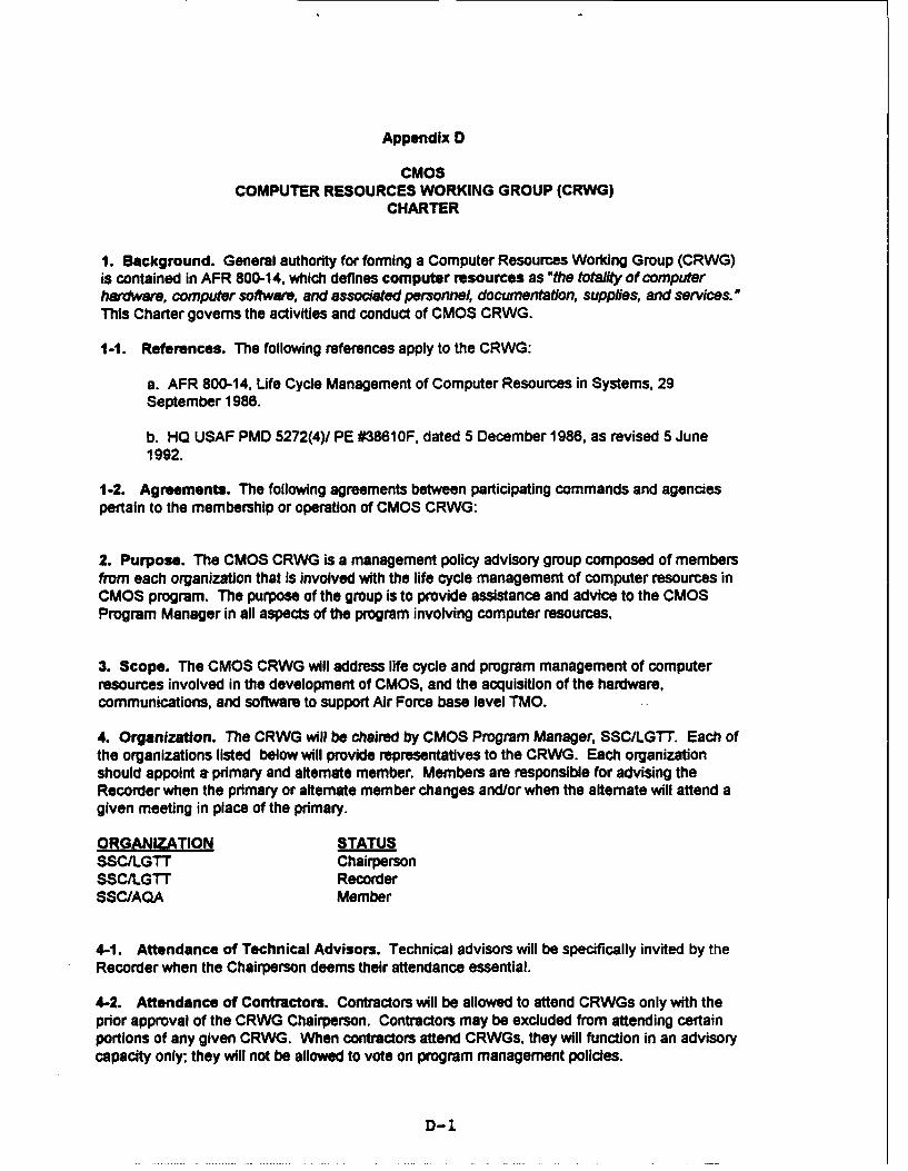
Appendix D
CMOSCOMPUTER RESOURCES WORKING GROUP (CRWG)
CHARTER
1. Background. General authority for forming a Computer Resources Working Group (CRWG)is contained in AFR 800-14, which defines computer resources as "the totali of computerhardware, computer software, and associated personnel, documentation, supplies, and services.This Charter governs the activities and conduct of CMOS CRWG.
1-1. References. The following references apply to the CRWG:
a. AFR 800-14, Life Cycle Management of Computer Resources in Systems, 29September 1986.
b. HO USAF PMD 5272(4)/ PE #3861 OF, dated 5 December 1986, as revised 5 June1992.
1-2. Agreements. The following agreements between participating commands and agenciespertain to the membership or operation of CMOS CRWG:
2. Purpose. The CMOS CRWG is a management policy advisory group composed of membersfrom each organization that is involved with the life cycle management of computer resources inCMOS program. The purpose of the group is to provide assistance and advice to the CMOSProgram Manager in all aspects of the program involving computer resources.
3. Scope. The CMOS CRWG will address life cycle and program management of computerresources involved in the development of CMOS, and the acquisition of the hardware,communications, and software to support Air Force base level TMO.
4. Organization. The CRWG will be chaired by CMOS Program Manager, SSC/LGTT. Each ofthe organizations listed below will provide representatives to the CRWG. Each organizationshould appoint a primary and alternate member. Members are responsible for advising theRecorder when the primary or altemate member changes and/or when the altemate will attend agiven meeting in place of the primary.
ORGANIZATION STATUSSSCILGTT ChairpersonSSC/LGTT RecorderSSC/AQA Member
4-1. Attendance of Technical Advisors. Technical advisors will be specifically invited by theRecorder when the Chairperson deems their attendance essential.
4-2. Attendance of Contractors. Contractors will be allowed to attend CRWGs only with theprior approval of the CRWG Chairperson. Contractors may be excluded from attending certainportions of any given CRWG. When contractors attend CRWGs, they will function in an advisorycapacity only; they will not be allowed to vote on program management policies.
D-1

5. Responsibilities. The following responsibilities, products and tasks of the CRWG and its
officers are assigned according to AFR 800-14:
5-1. Chairperson. The CRWG Chairperson will:
a. Serve as the primary point of contact on life cycle management matters for the CMOSprogram.
b. Serve as the CRWG's voice to the CMOS program management staff on computerresource life cycle management matters.
c. Coordinate with other CMOS working groups as necessary (e.g., Test Plan WorkingGroup (TPWG)).
d. Convene the CRWG as required to revise CMOS CRLCMP or provide technicaladvice.
5-2. Recorder. The CRWG Recorder (SSC/LGTT) will:
a. Schedule CRWG meetings called by the Chairperson and notify members.
b. Ensure minutes are taken and verify their accuracy.
c. Serve as the membership's primary point of contact for monitoring action items,and passing recommendations to the program office.
d. Establish agendas for meetings based on recommendations from the members anddirection of the Chairperson.
e. Prepare, publish, distribute, and update the CRWG charter.
f. Prepare, publish, and distribute minutes of the CRWG.
5-3. Members. The CRWG Members will:
a. Serve as their organizations' primary points of contact on life cycle managementmatters.
b. Assist in the preparation and review of management documents for the CMOSprogram (e.g., the CRLCMP).
c. Brief their organizations' program management issues and concems to the CRWGas necessary.
d. Ensure their organizations are fully aware of any CMOS requirements that may
impact the organization.
e. Respond to action items assigned during CRWGs.
f. Submit proposed agenda items to the CRWG Recorder.
5-4. Advisors. Advisors to the CRWG will:
a. Provide technical advice on issues within their areas of expertise.
D-2

b. Brief the CRWG as required on topics within their areas of expertise.
5-6. Products and Tasks. The CRWG plays a major role in the management of computerresources in the CMOS system. The CRWG will:
a. Write, update as necessary, and monitor compliance with the CRLCMP.
b. Monitor compliance of the program with computer resources policy, plans,procedures, and standards.
c. Select a software support concept and document it in the CRLCMP.
(1) Describe the support concept in sufficient detail to account for systempeculiarities and existing conditions.
(2) Categorize each software functional requirement as either a mission orsystem function.
(3) Further categorize each CSCI as either a mission or system CSCI after theallocated baseline is authenticated.
d. Actively participate in all aspects of the program involving computer resources(program management reviews, design reviews, audits, etc.).
e. Advise the program manager in all areas relating to the acquisition and support of
computer resources.
f. Integrate software test activities with the overall test program through a TPWG.
g. Assist the program manager to identify, assess, and control risks associated withcomputer resources.
h. Assess how much and what type of flexibility and spare capacity (to allow for growthduring development and modification during system deployment) is cost-effectiveand document recommendations in the CRLCMP.
i. Analyze existing software support facilities and tools for modification or upgrade
when evaluating support resources alternatives.
j. Analyze inter service su.pport alternatives along with other support concepts.
k. Coordinate the application of computer security concepts and guidance to the system.
I. Develop alternatives for computer resources life cycle support.
(1) Develop a preliminary allocation of software support responsibility.
(2) Study the potential for organic and contractor support.
(3) Identify candidate organizations for performing software support.
m. Define the appropriate scope of IV&V and develop a recommended approach.
D-3

n. Evaluate the use of standard equipment, high order languages, instruction setarchitectures, and interfaces.
o. Identify anL proritize the required software quality factors such as interoperability,portability, flexibility, usability, reusability, maintainability, integrity, reliability,correctness, testability, and efficiency.
S. Procedures. The CMOS CRWG will be conducted in accordance with the followingprocedures.
6-1. Meetings. CRWG meetings will be held at the call of the CRWG Chairperson and at othertimes as deemed appropriate. CRWG members may request a meeting by submitting proposedagenda items to the CRWG Recorder. When a CRWG meeting is anticipated, the membersshould be asked to propose agenda items. All the items on the agenda should be sent to themembers far enough in advance of the CRWG meeting to obtain input from the memberorganizations. Each organization will plan and fund for their participation at the meetings. TheCRWG meeting may be hosted by various organizations as agreed to by the CRWG.
6-2. Action Items. The CRWG is an advisory body to the program manager. The programmanager is responsible for the acquisition management of the system, including computerresources. As the Chairperson, the program manager will assign management issues as actionitems to members of the CRWG for resolution. Those issues may also be brought before theCRWG for resolution. If the CRWG cannot resolve an issue, it must notify the program managerwho is still responsible for resolving the issue through other means such as program reviews,senior level steering committees, or direct contact with command Office of Primary Responsibility(OPR).
D-4

Appendix E
Risk Management Plan
A Risk Management Plan is being developed for CMOS due to the plan to change hardwareplatforms for the Host Processor software and is due to be completed by 26 Feb 1993.
E-1

Appendix F
Detailed System Description
Refer to the Final System/Segment Design Document, Change 02, Increment II, dated 13December 1990, for a detailed description of CMOS processors and CSCIs.
F-1

Appendix Q
Security Assistance
This appendix is not applicable to the CMOS Program, There are currently no plans for sale ofCMOS technology to foreign countries.
G-1