technical report 1 - penn state college of engineering · technical report 1 ... asce 7-05 and aci...
TRANSCRIPT

Technical Report 1
Alyssa Stangl | Structural Option | Advisor: Dr. Linda Hanagan
La Jolla Commons Phase II Office Tower San Diego, California
October 28, 2013

2 | P a g e
Alyssa Stangl [Structural]
Table of Contents Executive Summary ....................................................................................................................................... 3
Building Introduction .................................................................................................................................... 4
Purpose and Scope .................................................................................................................................... 4
Building General Description .................................................................................................................... 4
Structural System .......................................................................................................................................... 8
Structural Framing Summary .................................................................................................................... 8
Materials ................................................................................................................................................... 8
Foundation ................................................................................................................................................ 9
Gravity System ........................................................................................................................................ 13
Floor System Overview ....................................................................................................................... 13
Floor System – Typical Bay .................................................................................................................. 15
Penthouse Floor/Roof Framing ........................................................................................................... 17
Penthouse Roof Slab and Framing ...................................................................................................... 19
Concrete Columns ............................................................................................................................... 21
Lateral System ......................................................................................................................................... 23
Special Features ...................................................................................................................................... 27
Design Codes and Standards ....................................................................................................................... 29
Codes and Standards .............................................................................................................................. 29
Special Seismic Code Considerations ...................................................................................................... 29
Design Loads ............................................................................................................................................... 30
National Code for Live Loads and Lateral Loadings ................................................................................ 30
Description of Loads and Method of Determination .............................................................................. 30
Gravity Load Path .................................................................................................................................... 31
Lateral Load Path .................................................................................................................................... 32
Conclusion ................................................................................................................................................... 33

3 | P a g e
Alyssa Stangl [Structural]
Executive Summary
La Jolla Commons Phase II Office Tower is a 13 story office building in San Diego, California. Each floor is
about 40,320 square feet, and the structure reaches 198 feet from ground level to the top of the
penthouse. With two levels of underground parking, the building extends about 20 feet below grade.
Serving as an office building for LPL Financial, the building has open floor plans and large areas of glass
curtain wall. La Jolla Commons Tower II received a LEED-CS Gold Certification and is the nation’s largest
and most advanced net-zero office building.
The building’s gravity system begins with a mat foundation, two stories below grade. The mat
foundation was chosen for its constructability, when compared to a system of footings and grade
beams. The super structure consists of two-way, flat plate, concrete slabs on a rectangular column grid.
A typical bay is 30 feet by 40 feet. Each level varies in thickness, ranging from 12 to 18 inches with
reinforcing, as required, by code. Camber was used for the slab at each level, excluding Lower Level 2
where the mat foundation serves as the floor. The designers determined that the large construction
loads would cause the slab to crack; therefore, slab deflections were calculated for a cracked slab
section. As a result, the deflections calculated for post-construction loading were significant. The
maximum camber applied to the slab is 2 ¼” at the center of a bay.
Laid out at the core of the building, the lateral system of La Jolla Commons Tower II consists of
reinforced concrete shear walls. Due to the high shear forces associated with earthquake loading in this
Seismic Category D structure, the diaphragm alone is not relied upon to transfer lateral loads to the
shear wall system; instead, collector beams are used to aid in the transfer of lateral loads at levels below
grade in the north-south direction.
La Jolla Commons Tower II has two unique structural and architectural features. The north and south
sides of the building feature 15 foot cantilevers that start at Level 3 and continue up to the roof level.
The structure of each cantilever is similar to that of the rest of slab; though, it does have additional
reinforcement. Also, the building has a plaza area on the Ground Level which carves out a portion of
Ground Level 1 and Level 2. Main building columns are exposed here, and additional 18 inch columns
are added to support the slab edge above.
La Jolla Commons Tower II was designed using the 2010 California Building Code which corresponds to
ASCE 7-05 and ACI 318-08. CBC 2010 and ASCE 7-05 were used to calculate live, wind, and earthquake
loads. ACI 318 – 08, Chapter 21, references the design of concrete Earthquake-Resistant structures, and
ASCE 7-05, Chapter 12, details the Seismic Design Requirements for Building Structures. Both of these
documents were used heavily in the design of LJC II in order to account for seismic loading and detailing.
La Jolla Commons Phase II Office Tower is full of educational value. It has several structural challenges
and unique conditions: punching shear, seismic loading and detailing, concrete shear wall design, and
computer modeling. The following report explains the building structure, design codes, and design
loads in more detail.
4 | P a g e
Alyssa Stangl [Structural]
Building Introduction
Purpose and Scope
The purpose of this technical report is to demonstrate an understanding of the structural systems
associated with La Jolla Commons Phase II Office Tower located in San Diego, California. The scope of
this report includes thorough descriptions of the physical existing conditions of the building and it’s
structural systems including the foundation, gravity system, lateral system, and joint details. It will also
cover important codes and sources of load information.
Building General Description
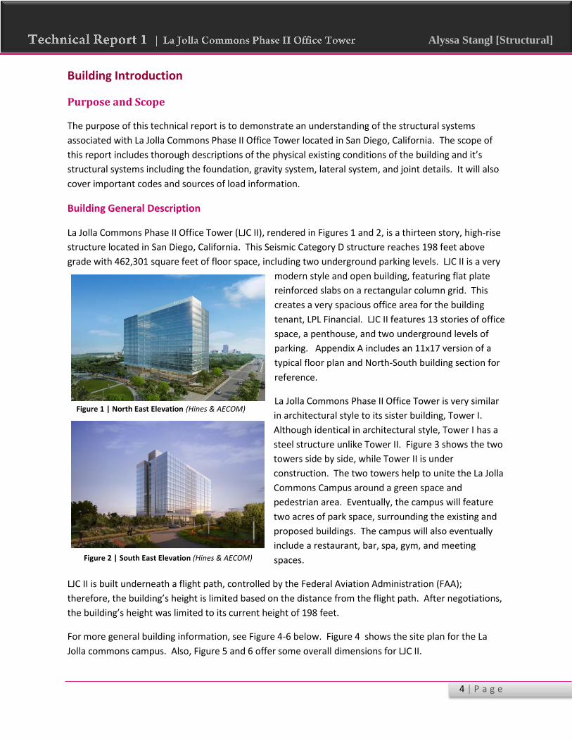
La Jolla Commons Phase II Office Tower (LJC II), rendered in Figures 1 and 2, is a thirteen story, high-rise
structure located in San Diego, California. This Seismic Category D structure reaches 198 feet above
grade with 462,301 square feet of floor space, including two underground parking levels. LJC II is a very
modern style and open building, featuring flat plate
reinforced slabs on a rectangular column grid. This
creates a very spacious office area for the building
tenant, LPL Financial. LJC II features 13 stories of office
space, a penthouse, and two underground levels of
parking. Appendix A includes an 11x17 version of a
typical floor plan and North-South building section for
reference.
La Jolla Commons Phase II Office Tower is very similar
in architectural style to its sister building, Tower I.
Although identical in architectural style, Tower I has a
steel structure unlike Tower II. Figure 3 shows the two
towers side by side, while Tower II is under
construction. The two towers help to unite the La Jolla
Commons Campus around a green space and
pedestrian area. Eventually, the campus will feature
two acres of park space, surrounding the existing and
proposed buildings. The campus will also eventually
include a restaurant, bar, spa, gym, and meeting
spaces.
LJC II is built underneath a flight path, controlled by the Federal Aviation Administration (FAA);
therefore, the building’s height is limited based on the distance from the flight path. After negotiations,
the building’s height was limited to its current height of 198 feet.
For more general building information, see Figure 4-6 below. Figure 4 shows the site plan for the La
Jolla commons campus. Also, Figure 5 and 6 offer some overall dimensions for LJC II.
Figure 1 | North East Elevation (Hines & AECOM)
Figure 2 | South East Elevation (Hines & AECOM)

5 | P a g e
Alyssa Stangl [Structural]
The façade of LJC II consists of a unitized curtain wall panel system on 2 3/4” x 6” framing members.
Dimensional stone, traditional windows, monumental storefront, and structural glass are also used on
the building’s façade, mostly at the building base.
After LJC Tower I achieved a LEED-CS Gold rating in
2008, Tower II was expected to reach a prestigious
level of sustainability as well. LJC II includes features
such as reclaimed water reuse, under-floor air
distribution system, double pane glazing with low
emissivity coating, and energy efficient lighting
systems. Furthermore, LJC II is the first Class A, Net-
Zero office building in the United States, and it is the
nation’s largest carbon-neutral office building to
date. Through methods of reduced consumption and
onsite generation, LJC II will actually return more power to the grid than it will use annually. LJC II also
received a LEED-CS Gold Certification upon structure and shell completion.
Figure 3 | South East Elevation (Hines & AECOM)
Figure 4 | Building Site Plan (Hines)
6 | P a g e
Alyssa Stangl [Structural]
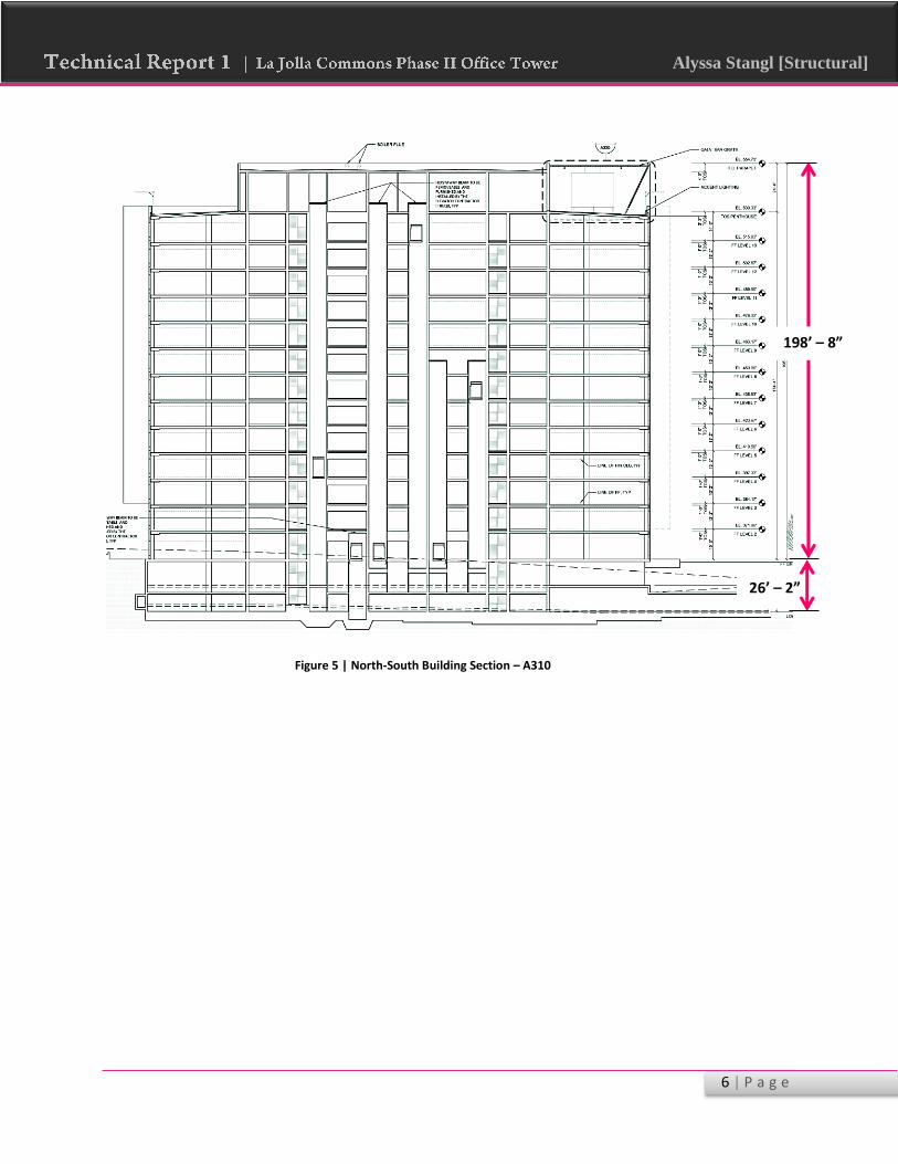
Figure 5 | North-South Building Section – A310
198’ – 8”
26’ – 2”

7 | P a g e
Alyssa Stangl [Structural]
`
Figure 6 | Typical Floor Plan - A109
NO
RTH
31
5’ –
0”
12
8’ –
8”
41
’-8
”
32
” –
0”
Typ
ical
Bay

8 | P a g e
Alyssa Stangl [Structural]
Structural System
Structural Framing Summary
La Jolla Commons Tower II is a, cast-in-place concrete structure using mild reinforcing. The foundation
consists of a concrete mat, ranging in thickness from 3 feet to 6.5 feet. The gravity system consists of
two way, flat plate, reinforced concrete slabs supported by a rectangular grid of reinforced concrete
columns. The lateral system is a series of shear walls located at the building’s core. Also, due to high
seismic loading (seismic category D), the lateral system includes collector beams on the Ground Level
and Lower Level 1, which are used to transmit the earthquake loads from the diaphragm into the shear
walls. The building also features two 15 foot cantilever sections at the North and South ends. The
mechanical penthouse, located on the roof, is framed in steel wide-flanges and hollow structural steel
members with a moment frame acting as the lateral system. All of the items mentioned in this summary
are described in detail in the following sections of this report.
Materials
La Jolla Commons Phase II office tower, primarily a concrete structure, employs several concrete and
reinforcing types, shown in Tables 1 and 2, depending on the use in the building. Although concrete is
the main structural material, information regarding steel is provided in Table 3 for the penthouse
framing.
Concrete Strengths (at 28 days, 0.5 max cement ratio)
Slab on Grade 3500 PSI Normal Weight Foundations 5000 PSI Normal Weight Shear Walls 6000 or 7000 PSI (per plans) Normal Weight Slabs and Beams 5000 PSI Normal Weight Columns 6000 or 7000 PSI (per plans) Normal Weight Basement Retaining Walls 5000 PSI Normal Weight Cantilever Retaining Walls 5000 PSI Normal Weight Built-up Slabs 4000 PSI Light Weight (110 PCF) All Other Concrete 4000 PSI Normal Weight
Steel Reinforcement
Typical Reinforcing Bars ASTM A-615, Grade 60 Shear Wall and Diaphragm Reinforcing ASTM A-706 Welded Rebar ASTM A-706
Structural Steel
All Structural Steel ASTM A-572, Grade 50 OR ASTM A992 Steel Braced Frame Beams and Columns ASTM A992 Structural Tubing ASTM A-500, Grade B (Fy = 46000 PSI) Structural Piping ASTM A-53, Grade B (Fy = 35,000 PSI)
Table 1 | Concrete Usage and Strengths
Table 2 | Steel Reinforcement and Standards
Table 3 | Structural Steel and Standards

9 | P a g e
Alyssa Stangl [Structural]
Foundation
The foundation system design was provided by Nabih Youssef Associates, the structural consultant for
LJC II, after review of the geotechnical report and recommendations of the geotechnical engineer,
Christian Wheeler Engineering. The final design consisted of a reinforced mat foundation system.
Geotechnical Report and Recommendations
The geotechnical report provided by Christian Wheeler Engineering, San Diego, California, was released
on January 24, 2012. Along with soil tests, they tested the feasibility of a 5-foot-thick, mat foundation,
proposed by Nabih Youssef Associates. After performing six subsurface explorations using Core
Penetration Tests and coordination with Nabih Youssef Associates, Christian Wheeler Engineering
created the soil map shown in Figure 7. The area in pink represents the area of the mat expected to be
supported by formational soil, and the orange shading represents the area previously undercut to 300
foot elevation. The numbers in blue represent the subgrade modulus of the soil in pounds per cubic
inch which is often used when deflection of the foundation is critical.
After testing was complete, Christian Wheeler Engineering provided the structural engineer with some
recommendations for the mat foundation system. Due to unique soil properties at the southeast corner
of the parking level, it is recommended that steps be taken to reduce settlement effects in the area
highlighted in red in Figure 8. This can be done by placing fill prior to mat construction. Results of
testing indicated an estimated settlement of 2.4 inches at the southeast corner, due to large surcharge
loads and saturated soils. About 23 feet of new fill will be used to reduce this settlement.
Results of testing indicated a settlement of 0.7 inches and an average mat pressure of about 2,500
pounds per square foot. In the final mat foundation layout, a factor of safety of two was applied. Other
soils information can be found in Table 4.
NORTH Figure 7 | La Jolla Commons Tower II Subgrade Modulus Layout – CPT Testing

10 | P a g e
Alyssa Stangl [Structural]
Soil Data: Office Tower II
Soil Site Class – C Report Date – January 24, 2012 Soil Engineer – Christian Wheeler Engineering
Fp 4000 Psf (fill) Subgrade Modulus Varies- See Figure 10 Fp max 8000+ Psf (formation Friction Coefficient 0.30
Pa unrestrained 40 Psf/ft Liquefaction No Pa restrained 60 Psf/ft Groundwater No
Pp 350 Psf/ft Corrosive No Pa seismic 8 Psf/ft inverted (kh=0.10g)
Foundation Walls
As stated above in the General Building Description, La Jolla Commons Tower II has two levels of
underground parking. As a result, concrete foundation walls were utilized around the building
perimeter to hold back soil loads. Typical foundation walls are 14” thick concrete with #7 bars at 12
inches on center (o.c.) at the exterior and #5 bars at 12 inches o.c. at the inside face, vertical
reinforcement. Also, #6 bars at 12 inches o.c. were provided for horizontal reinforcement.
The southeast corner, the area requiring surcharge loading has 16 inch foundation walls with #9 vertical
bars at 12 inches o.c. (outside face) and #6 bars at 10 inches o.c. (inside face). Also, #6 horizontal bars
were provided at 12inches o.c. The thicker walls are necessary due to increased soil pressures due to
soil saturation. This area is highlighted in red in Figure 8.
Table 4 | Soil Data – S001
Surcharge
Area
NORTH Figure 8 | Southeast Corner Surcharge - S.1L2
11 | P a g e
Alyssa Stangl [Structural]
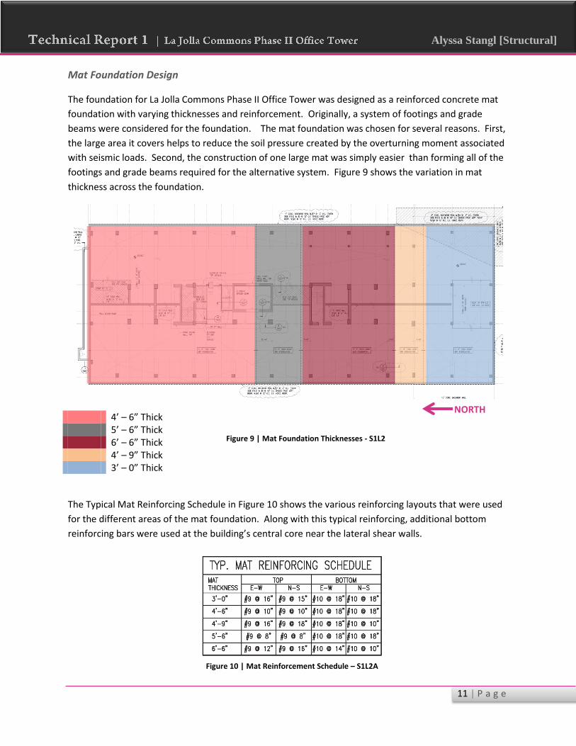
Figure 9 | Mat Foundation Thicknesses - S1L2
Mat Foundation Design
The foundation for La Jolla Commons Phase II Office Tower was designed as a reinforced concrete mat
foundation with varying thicknesses and reinforcement. Originally, a system of footings and grade
beams were considered for the foundation. The mat foundation was chosen for several reasons. First,
the large area it covers helps to reduce the soil pressure created by the overturning moment associated
with seismic loads. Second, the construction of one large mat was simply easier than forming all of the
footings and grade beams required for the alternative system. Figure 9 shows the variation in mat
thickness across the foundation.
The Typical Mat Reinforcing Schedule in Figure 10 shows the various reinforcing layouts that were used
for the different areas of the mat foundation. Along with this typical reinforcing, additional bottom
reinforcing bars were used at the building’s central core near the lateral shear walls.
4’ – 6” Thick 5’ – 6” Thick 6’ – 6” Thick 4’ – 9” Thick 3’ – 0” Thick
NORTH
Figure 10 | Mat Reinforcement Schedule – S1L2A
12 | P a g e
Alyssa Stangl [Structural]
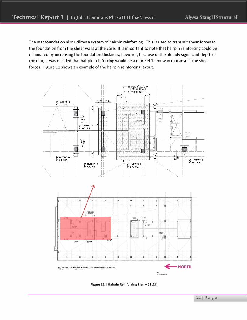
The mat foundation also utilizes a system of hairpin reinforcing. This is used to transmit shear forces to
the foundation from the shear walls at the core. It is important to note that hairpin reinforcing could be
eliminated by increasing the foundation thickness; however, because of the already significant depth of
the mat, it was decided that hairpin reinforcing would be a more efficient way to transmit the shear
forces. Figure 11 shows an example of the hairpin reinforcing layout.
Figure 11 | Hairpin Reinforcing Plan – S1L2C
NORTH
13 | P a g e
Alyssa Stangl [Structural]
Gravity System
Floor System Overview
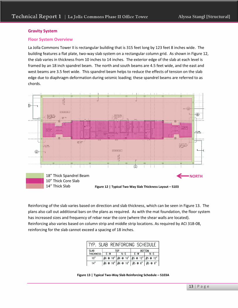
La Jolla Commons Tower II is rectangular building that is 315 feet long by 123 feet 8 inches wide. The
building features a flat plate, two-way slab system on a rectangular column grid. As shown in Figure 12,
the slab varies in thickness from 10 inches to 14 inches. The exterior edge of the slab at each level is
framed by an 18 inch spandrel beam. The north and south beams are 4.5 feet wide, and the east and
west beams are 3.5 feet wide. This spandrel beam helps to reduce the effects of tension on the slab
edge due to diaphragm deformation during seismic loading; these spandrel beams are referred to as
chords.
18” Thick Spandrel Beam 10” Thick Core Slab 14” Thick Slab
Reinforcing of the slab varies based on direction and slab thickness, which can be seen in Figure 13. The
plans also call out additional bars on the plans as required. As with the mat foundation, the floor system
has increased sizes and frequency of rebar near the core (where the shear walls are located).
Reinforcing also varies based on column strip and middle strip locations. As required by ACI 318-08,
reinforcing for the slab cannot exceed a spacing of 18 inches.
Figure 12 | Typical Two Way Slab Thickness Layout – S103
Figure 13 | Typical Two-Way Slab Reinforcing Schedule – S103A
NORTH

14 | P a g e
Alyssa Stangl [Structural]
Shown in Figure 14, typical bay sizes are 30 feet by 40 feet at the east and west sides of the core. Bay
sizes in the core vary due to shear wall placement. Also, column spacing at the core does not exactly
match that of the exterior columns; however, the largest core bay size is 30 feet by 30 feet.
Camber of the structural slabs is used extensively for La Jolla Commons Tower II, a sample of which can
be viewed in Figure 15. Due to the fast construction of LJC II, construction loads were significant and
played a major role in the design. Designers assumed that the slab would be loaded to the limit during
construction, causing some cracking. The slab was then analyzed for creep as a cracked section to
determine the worst possible conditions; deflections were great enough that camber was required.
Nabih Youssef Associates consulted documents such as ACI 435 to determine creep and shrinkage.
Figure 14 | Typical Bay Sizes from Level 9-13 – S103A
Figure 15 | Typical Slab Camber Plan – S103B
NORTH
Core
Bay
30’x30’
Bay
Typical
Bay
30’x40’

15 | P a g e
Alyssa Stangl [Structural]
Floor System – Typical Bay
A typical 30 foot by 40 foot bay was selected from the framing plan for Levels 3 – 7 and can be seen
highlighted in pink on Figure 14. This typical bay is a 14 inch two-way slab. It also has a 4.5 foot by 18
inch spandrel beam
The slab follows the typical slab reinforcing schedule which was shown previously in Figure 13.
Additional reinforcement was needed at the column strips in both directions of the slab. See Figure 16
for additional bar frequency, size, and location. “B” indicates bottom bars at the middle strip. “T”
indicates top bars at the middle strip. All the listed frequencies are spaced equally along the width of
the strip.
Also, note that 90 degree hooks are used to terminate the bars in the spandrel beam. The shear walls
also create a unique condition, requiring an increase in reinforcing to transmit shear forces. A detail of
the slab reinforcing, shown in Figure 17, shows the layout of bars in the column strip and middle strip
cross-sections.
Figure 16 | Typical Bay Column Strip Reinforcing – S109A
M.S. C.S. C.S.
Figure 17 | Typical Flat Slab Reinforcing Placing Detail – 12|S602

16 | P a g e
Alyssa Stangl [Structural]
As previously mentioned, the typical bay has a cambered slab. This particular bay has a maximum
camber of 2 ¼ inches at the center of the span and a minimum camber of ¼ inch at the exterior edge of
the bay which can be seen in Figure 18. Camber values at all column and wall supports are taken as
zero.
Figure 18 | Typical Bay Camber Plan – S109B

17 | P a g e
Alyssa Stangl [Structural]
Penthouse Floor/Roof Framing
The penthouse/roof level is located above the thirteenth floor of LJC II. The roof slab is designed to
behave similarly to the floor systems below. As is shown in Figure 19, the flat plate, two-way slab is 11
inches thick with an 18” deep spandrel beam framing the slab edges. Like the floor system, the beam is
3.5 feet wide at the north and south edges and is 4.5 feet wide at the east and west edges.
18” Thick Spandrel Beam 11” Thick Slab
Much like the floor, the roof/penthouse slab has a typical reinforcing schedule as seen in Figure 20. It
also has additional supplemental reinforcing as required by loads. Longitudinal reinforcing is terminated
at spandrel beams with 90 degree hooks.
NORTH
Figure 19 | Roof/Penthouse Slab Thickness – S114
Figure 20 | Roof/Penthouse Slab Reinforcing Schedule – S114

18 | P a g e
Alyssa Stangl [Structural]
Again, like the floor system, camber is utilized on the roof system. Camber of the roof/penthouse slab
ranges from ¼ inch at the edges to 3 ½ inches at the center of each bay.
Unlike the floor system, the roof slab is supplemented with drop panels along column lines E and W,
highlighted in pink in Figure 21, to support increased shear, flexure, and deflections due to high roof
loads and long spans. There are four of these drop panels, and they are each 12 feet x 12 feet x 14
inches thick. The final component of the roof/penthouse consists of concrete beams and spandrel
beams used to frame around the elevators, stairways, and shear walls, which are highlighted in red and
yellow in Figure 21.
Drop Panels Spandrel Concrete Beams Regular Concrete Beams
Figure 21 | Roof/Penthouse Drop Caps and Concrete Beams – S114
NORTH
19 | P a g e
Alyssa Stangl [Structural]
Penthouse Roof Slab and Framing
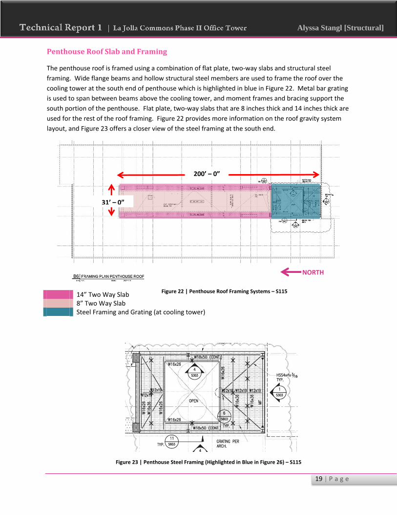
The penthouse roof is framed using a combination of flat plate, two-way slabs and structural steel
framing. Wide flange beams and hollow structural steel members are used to frame the roof over the
cooling tower at the south end of penthouse which is highlighted in blue in Figure 22. Metal bar grating
is used to span between beams above the cooling tower, and moment frames and bracing support the
south portion of the penthouse. Flat plate, two-way slabs that are 8 inches thick and 14 inches thick are
used for the rest of the roof framing. Figure 22 provides more information on the roof gravity system
layout, and Figure 23 offers a closer view of the steel framing at the south end.
14” Two Way Slab 8” Two Way Slab Steel Framing and Grating (at cooling tower)
Figure 22 | Penthouse Roof Framing Systems – S115
NORTH
Figure 23 | Penthouse Steel Framing (Highlighted in Blue in Figure 26) – S115
200’ – 0”
31’ – 0”

20 | P a g e
Alyssa Stangl [Structural]
Roof Steel Framing Connections
As mentioned above, the penthouse is made up of steel framing, including wide-flange and hollow
structural steel sections. Most connections for the penthouse are pinned, except for the moment
frame. The fixed connection between the base of the moment frame and the concrete slab is shown in
Figure 24. The column-beam moment connection is shown in Figure 25.
Figure 24 | Steel Column Moment Connection – 3|S303 Figure 25 | Steel Colum to Beam Moment Connection 2|S303

21 | P a g e
Alyssa Stangl [Structural]
Concrete Columns
The entire gravity system is supported by a series of columns of various sizes on a rectangular column
grid. Column sizes range from a maximum size of 42 inches by 42 inches at Lower Level 2 (lowest level
of the underground parking garage) to a minimum size of 24 inches by 24 inches at the penthouse.
Vertical reinforcing varies significantly based on column height, dimensions, and location. However, all
columns have #5 ties spaced at 4 to 6 inches on center. Minimum requirements from ACI 318-08 (CBC
2010) for spacing and quantity of reinforcement have been met. There are twelve types of concrete
column layouts for LJC II; four examples are provided below in Figure 26. Column types vary with the
column height and location.
When the columns were designed, they were considered fixed when applying only gravity loads to
account for any eccentricity in the loading. However, when the lateral system was designed, the
columns were considered pinned. In the event of an earthquake, the column bases would crack and
create a pinned condition; the columns would, therefore, take minimal lateral load.
Figure 26 | Typical Gravity Column Types – S613

22 | P a g e
Alyssa Stangl [Structural]
Concrete Column Connections
As shown in Figure 27, the concrete columns are connected to the mat foundation by continuous
vertical bars that extend into the foundation and terminate with 90 degree hooks. The connection is
fixed in a gravity loaded condition. However, as mentioned above, the bases of the columns are
assumed to crack in the event of an earthquake, creating a pinned condition. As a result, the columns
will take minimal lateral load.
The edge column to spandrel beam connection is critical due to punching shear and slab deflection
concerns under seismic loading. The beam rests on the column below; at this column to slab interface, a
spandrel beam is introduced with shear reinforcement. Figure 28 is a typical detail of the spandrel
beam-column connection. Due to increased punching shear concerns and considerations for seismic-
load-induced diaphragm deflection causing tension at the slab edge, the spandrel beam is provided with
additional longitudinal and shear reinforcement. Column to slab connections are typically made through
the use of continuous or lap spliced rebar matching slab reinforcement and stud rails.
Figure 27 | Column to Mat Foundation – 9|S610 Figure 28 | Edge Column and Spandrel Beam Detail – 2|S616

23 | P a g e
Alyssa Stangl [Structural]
Lateral System
Shear Walls and Moment Frame
La Jolla Commons Phase II Office Tower has a lateral system of concrete shear walls; moment frames are
utilized for the lateral support of the penthouse at the roof cooling tower. All lateral systems were
designed and detailed following Chapter 21 of ACI 318-08 for earthquake loading. See Figure 29 for the
concrete shear wall layout for the lateral force resisting system. Sheets S103, S300, S301, and S302 are
included in Appendix B. These plans show details of all shear walls, including reinforcement, thickness,
and location on plan. S103 is a typical structural plan to aid in locating the shear walls. Figures 30 and
31 provide more information regarding the penthouse moment frame.
Figure 29 | Typical Shear Wall Layout – S109
Figure 30 | Penthouse Moment Frame Layout – S109 Figure 31 | Penthouse Moment Frame – S303
W18x50
W1
0x4
5
W1
0x4
5
NORTH

24 | P a g e
Alyssa Stangl [Structural]
Shear Wall Connections
The connection between the shear walls and the mat foundation is critical to the lateral system. The
shear walls must be moment connected to the foundation. This is accomplished through the use of
dowels that are embedded into the shear walls and hook down into the matt foundation with a 90
degree hook. Figure 32 shows a detail of dowels placed to match the vertical wall reinforcing.
The slab and shear walls are poured monolithically and are connected by means of bent #6 bars at 3
inches on center, as shown in Figure 33. This rebar is in addition to the rebar already required for the
walls and the slab.
Figure 32 | Shear Wall Connection to Mat Foundation – 2|S300
Figure 33 | Shear Wall Connection to Slabs – 7|S601
25 | P a g e
Alyssa Stangl [Structural]
Collector Beams
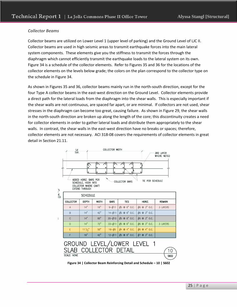
Collector beams are utilized on Lower Level 1 (upper level of parking) and the Ground Level of LJC II.
Collector beams are used in high seismic areas to transmit earthquake forces into the main lateral
system components. These elements give you the stiffness to transmit the forces through the
diaphragm which cannot efficiently transmit the earthquake loads to the lateral system on its own.
Figure 34 is a schedule of the collector elements. Refer to Figures 35 and 36 for the locations of the
collector elements on the levels below grade; the colors on the plan correspond to the collector type on
the schedule in Figure 34.
As shown in Figures 35 and 36, collector beams mainly run in the north-south direction, except for the
four Type A collector beams in the east-west direction on the Ground Level. Collector elements provide
a direct path for the lateral loads from the diaphragm into the shear walls. This is especially important if
the shear walls are not continuous, are spaced far apart, or are minimal. If collectors are not used, shear
stresses in the diaphragm can become too great, causing failure. As shown in Figure 29, the shear walls
in the north-south direction are broken up along the length of the core; this discontinuity creates a need
for collector elements in order to gather lateral loads and distribute them appropriately to the shear
walls. In contrast, the shear walls in the east-west direction have no breaks or spaces; therefore,
collector elements are not necessary. ACI 318-08 covers the requirements of collector elements in great
detail in Section 21.11.
Figure 34 | Collector Beam Reinforcing Detail and Schedule – 10 | S602

26 | P a g e
Alyssa Stangl [Structural]
Figure 35 | Lower Level 1 Collector Beams – S1L1C
Figure 32 | Ground Level Collector Beams – S1L1C
Figure 36 | Ground Level Collector Beams – S1L1C
NORTH
27 | P a g e
Alyssa Stangl [Structural]
Special Features
North and South Cantilevers
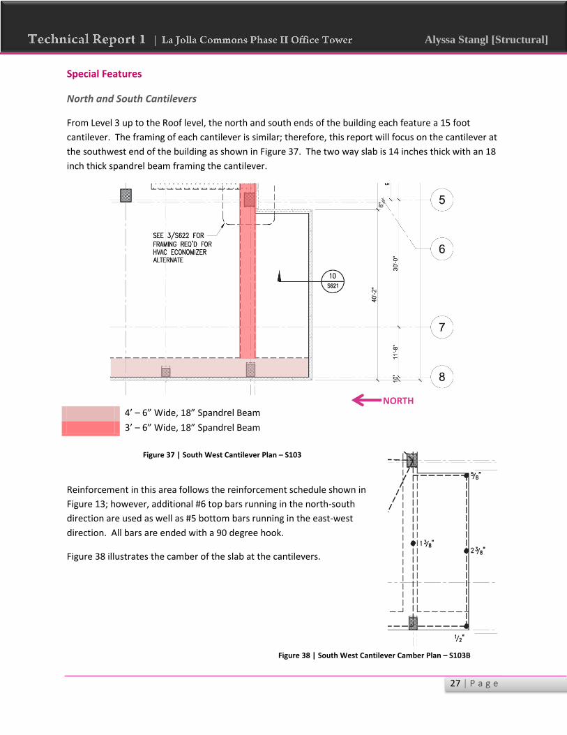
From Level 3 up to the Roof level, the north and south ends of the building each feature a 15 foot
cantilever. The framing of each cantilever is similar; therefore, this report will focus on the cantilever at
the southwest end of the building as shown in Figure 37. The two way slab is 14 inches thick with an 18
inch thick spandrel beam framing the cantilever.
4’ – 6” Wide, 18” Spandrel Beam
3’ – 6” Wide, 18” Spandrel Beam
Reinforcement in this area follows the reinforcement schedule shown in
Figure 13; however, additional #6 top bars running in the north-south
direction are used as well as #5 bottom bars running in the east-west
direction. All bars are ended with a 90 degree hook.
Figure 38 illustrates the camber of the slab at the cantilevers.
Figure 37 | South West Cantilever Plan – S103
NORTH
Figure 38 | South West Cantilever Camber Plan – S103B
28 | P a g e
Alyssa Stangl [Structural]
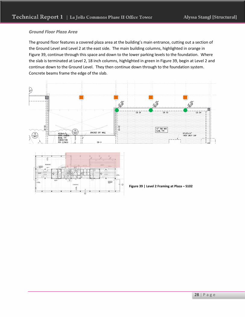
Ground Floor Plaza Area
The ground floor features a covered plaza area at the building’s main entrance, cutting out a section of
the Ground Level and Level 2 at the east side. The main building columns, highlighted in orange in
Figure 39, continue through this space and down to the lower parking levels to the foundation. Where
the slab is terminated at Level 2, 18 inch columns, highlighted in green in Figure 39, begin at Level 2 and
continue down to the Ground Level. They then continue down through to the foundation system.
Concrete beams frame the edge of the slab.
Figure 39 | Level 2 Framing at Plaza – S102

29 | P a g e
Alyssa Stangl [Structural]
Design Codes and Standards
Codes and Standards
California Building Code 2010 (CBC 2010 Adopts IBC 2009 with some additions and changes)
Metal Building Manufacturers Association
o MBMA Recommended Design Practice Manual
American Iron and Steel Institute
o Applicable sections of the AISI Specifications
American Society of Civil Engineering
o ASCE 7-05 (as Adopted by IBC 2009) – Minimum Design Loads for Buildings
American Concrete Institute
o ACI 318 – 08 (as Adopted by IBC 2009) – Building Code Requirements for Structural
Concrete
Special Seismic Code Considerations
ACI 318 – 08 Chapter 21 is referenced quite often in the design of LJC II. This chapter is for the design of
concrete Earthquake-Resistant Structures. This section discusses detailing requirements for all aspects
of earthquake resistant building components, including structural and non-structural elements.
ASCE 7 – 05 Chapter 12 is also used quite often in the design of LJC II. This chapter details the Seismic
Design Requirements for Building Structures, including system selection and load analysis. Based on this
section, LJC II has a Type 1A Torsional Irregularity, which would need to be considered.
30 | P a g e
Alyssa Stangl [Structural]
Design Loads
National Code for Live Loads and Lateral Loadings
Live and lateral loads were calculated following CBC 2010 which adopts IBC 2009 and ASCE 7 -05.
Ultimately, ASCE 7 – 05 is used to calculate all wind, seismic, snow, and soil loads. Live loads come from
a modified table of live loads in Section 1607 of CBC 2010. The building was designed using Strength
Design methods.
Description of Loads and Method of Determination
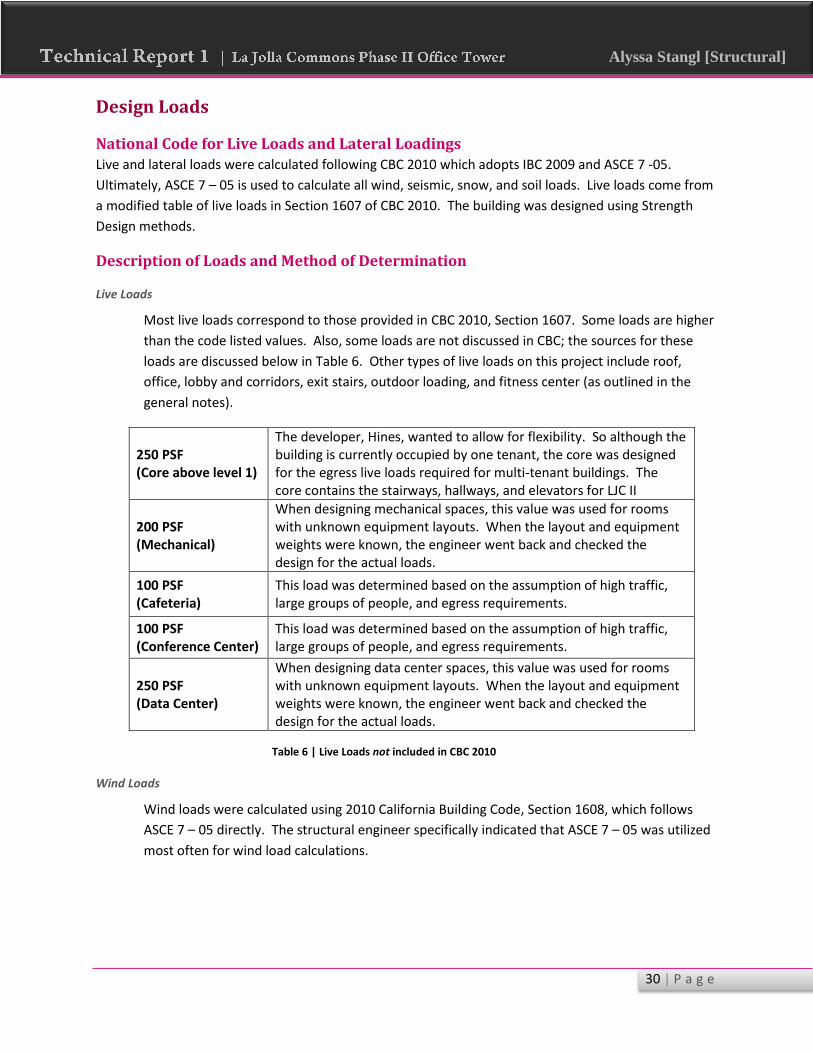
Live Loads
Most live loads correspond to those provided in CBC 2010, Section 1607. Some loads are higher
than the code listed values. Also, some loads are not discussed in CBC; the sources for these
loads are discussed below in Table 6. Other types of live loads on this project include roof,
office, lobby and corridors, exit stairs, outdoor loading, and fitness center (as outlined in the
general notes).
250 PSF (Core above level 1)
The developer, Hines, wanted to allow for flexibility. So although the building is currently occupied by one tenant, the core was designed for the egress live loads required for multi-tenant buildings. The core contains the stairways, hallways, and elevators for LJC II
200 PSF (Mechanical)
When designing mechanical spaces, this value was used for rooms with unknown equipment layouts. When the layout and equipment weights were known, the engineer went back and checked the design for the actual loads.
100 PSF (Cafeteria)
This load was determined based on the assumption of high traffic, large groups of people, and egress requirements.
100 PSF (Conference Center)
This load was determined based on the assumption of high traffic, large groups of people, and egress requirements.
250 PSF (Data Center)
When designing data center spaces, this value was used for rooms with unknown equipment layouts. When the layout and equipment weights were known, the engineer went back and checked the design for the actual loads.
Wind Loads
Wind loads were calculated using 2010 California Building Code, Section 1608, which follows
ASCE 7 – 05 directly. The structural engineer specifically indicated that ASCE 7 – 05 was utilized
most often for wind load calculations.
Table 6 | Live Loads not included in CBC 2010

31 | P a g e
Alyssa Stangl [Structural]
Seismic Design Loads
Seismic Design loads are based on the 2010 California Building Code, Section 1613. This section
states that structures shall be designed to resist the effects of earthquake motions in
accordance with ASCE 7, excluding Chapter 14 (Material Specific Seismic Design and Detailing
Requirements) and Appendix 11A. Seismic design loads were calculated with the aid of the
geotechnical report provided by Christian Wheeler Engineering. These loads were calculated
using the Response Spectrum Analysis Method, with a Seismic Category D.
Snow Loads
Snow loads were found using 2010 California Building Code, Section 1608, corresponding to
requirements of ASCE 7 – 05.
Soil Loads
Soil loads were determined using 2010 California Building Code, Section 1610, along with the
geotechnical report provided by Christian Wheeler Engineering.
Dead Loads
Dead loads were determined using industry standard values and engineering judgment.
Assumptions were used for flooring, ceiling, MEP, fire protection, and other items. However,
because the floor is essentially hollow for the under-floor air distribution system, 2x2 concrete
tiles on metal pedestals were attached to the bottom of the slab to decrease echoing and such
associated with the hollow floor. This causes a considerable increase in the floor dead load.
Gravity Load Path
The gravity system, as discussed in detail above, consists of a two way, flat plate slab on a rectangular
grid of concrete columns, which tie into the mat foundation below grade.
Floor Loads
Floor loads will contact the two way, concrete slab first. The loads will then be transferred by
the slab to the columns directly below at the core and perimeter. This will occur at each floor,
causing the columns to accumulate more dead and live load as we proceed down the building
(hence the increase in column sizes and reinforcing). When the columns reach the mat, loads
will be transferred to the mat foundation. The column loads will be spread out by the mat to
meet the bearing capacity of the soil.
Curtain Wall
The curtain wall is typically hung from the spandrel beams framing the concrete slab edges. The
beam transfers the exterior wall load to the exterior columns, which will direct the loads down
to the foundation in a similar manner to the floor loads.

32 | P a g e
Alyssa Stangl [Structural]
Lateral Load Path
Wind Loads
Wind pressures will be collected on the building enclosure. The building enclosure will then
transmit these forces into the diaphragm. Because wind shear forces are small enough, the
diaphragm can transmit these shear forces into the shear walls at the building’s core. Lateral
loads are collected at each level and carried down to the foundation by means of the shear
walls.
Seismic Loads
North South Direction: Inertial seismic forces will be calculated as story shears at each level of
the building. These forces will initiate at the center of mass of each level. Because the
earthquake induced shear is so high for this building, the diaphragm alone cannot be relied
upon to transmit the shear forces to the lateral system in the north-south direction at the levels
below grade. Therefore, north-south seismic loads will be transmitted to collector elements
near the building’s core. These elements will transfer the lateral load to the shear walls. For the
levels above grade, the lateral forces will be transmitted through the slab directly to the shear
wall system. These lateral loads will be collected at each level and carried down to the
foundation by the means of the core shear walls.
East West Direction: Inertial seismic forces will be calculated as story shears at each level of the
building. These forces will initiate at the center of mass of each level. The earthquake induced
forces in the east-west direction will be transmitted through the diaphragm to the shear walls.
These lateral loads will be collected at each level and carried down to the foundation by means
of the core shear walls.

33 | P a g e
Alyssa Stangl [Structural]
Conclusion
This report has analyzed the existing conditions for the building structure for La Jolla Commons Phase II
Office Tower in San Diego, California. The structural systems, design loads, and design codes have been
discussed in detail. LJC II offers several challenges moving forward.
This LEED Certified, net-zero, office building features large open office spaces, 13 foot floor-to-floor
heights, and large expansions of exterior glass. When redesign is performed, these features should be
considered and maintained if possible. Another challenge for LJC II is the building’s height limit imposed
by the FAA due to flight path regulations. The building’s current 198 foot height is at the maximum
allowable height; therefore, when redesign is performed, the building height cannot increase without
more collaboration with local authorities.
The gravity system for LJC II consists of a two-way, flat plate, slab system on a rectangular column grid.
Punching shear is a critical failure mode associated with this system. As building systems are changed in
the future, the effect of punching shear, slab deformations, and other failure mechanisms must be
considered.
Looking at the building’s lateral system, the seismic design and detailing of the concrete shear walls will
have a significant effect on future analysis and redesign. Being that the structure is Seismic Category D,
any changes should be checked against the proper codes. Important references for seismic
considerations will include ACI 318 – 08 Chapter 21 and ASCE 7 – 05 Chapter 12. Furthermore, LJC II was
designed using CBC 2010 which references IBC 2009 (ACI 318-08 and ASCE 7-05). The most recent
version of the California Building Code is CBC 2013 which references IBC 2012 (ACI 318-11 and ASCE 7-
10). In future redesign assignments, code changes may need to be explored.
La Jolla Commons Tower II has several inherent modeling challenges. When models are created in the
future, the integration of lateral and gravity system models should be carefully considered. For
example, when analyzing the lateral shear walls for seismic loading, should the concrete columns and
slab be included? How accurate will the model or the design be based on the model created? Great
care must be taken to make sure the building functions correctly under earthquake and gravity loading;
the model should strive to mimic the structural behavior that is desired.
La Jolla Commons Phase II Office Tower will prove to be an educational challenge due to its height,
seismic loading, intricate detailing, and modeling concerns.