technical reference guide - djb instruments reference guide englis… · dynamic don who will offer...
TRANSCRIPT

Technical Reference Guide

www.djbinstruments.com | 01
A UK company providing in-house design, manufacture and assembly with a strong customer focus.
For data sheets please visit our website.
DJB Instruments UK Ltd has been manufacturing accelerometers, cables, instrumentation and accessories for over 40 years. Originally established as DJ Birchall Ltd in 1974, it changed name in 2010 after the death of the company’s founder, Don Birchall. After some major restructuring and re-investment, the company is now enjoying a period of expansion with truly global aspirations.
DJB is proud to uphold the traditions of quality British manufacturing that has been admired for so long around the world and also maintains the fundamental engineering innovation that Don Birchall was well renowned for. Still the only global accelerometer manufacturer using the Konic Shear design patented by Don and offering significant improvements in performance and cross axis reduction, it continues future innovation through joint academic research programs and internal material developments.
As homage to our founder we have introduced Dynamic Don who will offer technical guidance in selecting and using accelerometers to ensure the very best data quality.
Hi, my name is Dynamic Don...I will be your guide to help you select the correct accelerometer, cable, signal conditioning and accessories. It is important to consider all the aspects to maximise the quality and accuracy of your data. Wherever you see me I will be providing some technical information.
The old adage of Rubbish In = Rubbish Out is very appropriate when using any sort of sensor. It may be the cheapest part of the acquisition and analysis system, but it is also the most important. Did you know that if you use the wrong accelerometer, cable or mounting and don’t calibrate regularly, you can introduce errors of up to 35% into your data!! The biggest problem is, you will know nothing about it and neither will your very expensive software that is analysing the signal. All it sees is a voltage and it will analyse whatever it is given. It is YOUR responsibility to handle accelerometers with care and make sure you use and install them correctly.
Remember… everyone at DJB is available to help!! Just call us on +44 (0)1638 712288 or email [email protected]
Dynamic Don Technical Information
03 | Accelerometer Selection – Points to consider
05 | Piezoelectric Accelerometers – The principle of operation and design
08 | IEPE & Charge Accelerometers – Pros and Cons
09 | Seismic & Water Cooled Accelerometers
11 | Accelerometer Specifications Explained
12 | Instrumentation – Points to consider
13 | Use of Modal / Impact Hammers
18 | Mounting Guide
19 | Cable Selection
22 | Training and Calibration
FM11310
03 | Piezoelectric Accelerometers 04 | Mono-axial Piezo-Tronic IEPE Accelerometers
05 | High Shock Mono-axial IEPE Accelerometers
06 | Tri-axial Piezo-Tronic IEPE Accelerometers
07 | Mono-axial Piezoelectric Accelerometers
08 | Tri-axial Piezoelectric Accelerometers
09 | Mono-axial Seismic Accelerometers
09 | Ultra High Temperature Exhaust & Turbo Charger Test Accels, 900°C
10 | Mono-axial Industrial Piezoelectric Accelerometers
11 | Piezoelectric Dynamic Pressure Transducers
11 | Low Cost Mono-axial Industrial IEPE Accelerometers
12 | Instrumentation
13 | IEPE Instrumented Impact Hammer Range
14 | Hand Held Calibrator / Hand Held Vibration Meter
15 | Source Amplifiers
16 | Converters, Integrators and Filters
17 | Portable and Rack Based Housings
18 | Cables and Accessories
19 | Connectors and Cables
20 | Mounting Studs, Magnets and Blocks
21 | Bespoke Junction Boxes
21 | Down Hole Seismic Sonde
22 | Training and Calibration

[email protected] | 02
Acc
esso
ries
Serv
ices
TypeMono-axial Piezo-Tronic IEPE Accelerometers A/128/VA/127/VA/124/EA/124/TEA/124/TSA/123/EA/123/SA/123/TSA/123/TEA/122/VA/120/VA/120/VTA/120/VTCA/120/VIA/120/VTIA/121/VA/121/VIA/1600/VA/1600/VTA/120/CRMono-axial Piezo-Tronic IEPE Accelerometers - High Shock A/161A/161-1A/162A/162-1A/163-1Tri-axial Piezo-Tronic IEPE AccelerometersAT/18AT/10AT/14AT/14/TBAT/11AT/13A/136/VA/131/VA/134/VA/134/V-3A/130/VA/130/V-1Mono-axial Piezoelectric Charge AccelerometersA/28/EA/25/EA/27/EA/24/EA/24/TEA/24/TSA/23/EA/23/SA/23/TEA/23/TSA/22A/20A/20/TA/20/TCA/29A/29/TA/29/TCA/21A/21/TA/21/TCA/600A/600/TTri-axial Piezoelectric Charge AccelerometersAT/08AT/01AT/04AT/04/TBA/38A/38-1A/31A/34A/34-2A/30A/30-1A/36A/36-1Mono-axial Charge Accelerometers - SeismicA/800A/800/TA/800/TCMono-axial IEPE Piezo-Tronic Accelerometers - SeismicA/1800/VA/1800/VTA/1800/VTCUltra high temperature Exhaust & Turbo charger test accel, 900 A/133/VA/33A/33-1Mono-axial Piezoelectric Accelerometers - IndustrialA/53/FA/53/F/HTA/52/FA/52/F/HTA/81/FA/81/F/HTA/301/FA/301/F/HTA/107/FA/107/F/HTA/1107/VA/172/VFMono-axial Piezoelectric Accelerometers - Low CostA/140A/140/SA/140/C
Index Piezoelectric AccelerometersSensitivity
1mV/g up to 10mV/g1mV/g up to 100mV/g1mV/g up to 200mV/g1mV/g up to 200mV/g1mV/g up to 200mV/g1mV/g up to 250mV/g1mV/g up to 250mV/g1mV/g up to 250mV/g1mV/g up to 250mV/g10mV/g up to 1V/g10mV/g up to 1V/g10mV/g up to 1V/g10mV/g up to 1V/g10mV/g up to 1V/g10mV/g up to 1V/g100mV/g up to 3V/g100mV/g up to 3V/g1V/g up to 10V/g1V/g up to 10V/g10mV/g • 100mV/g
0.5mV/g0.5mV/g0.2mV/g0.2mV/g0.1mV/g
1mV/g up to 10mV/g1mV/g up to 100mV/g1mV/g up to 200mV/g1mV/g up to 200mV/g1mV/g up to 100mV/g1mV/g up to 100mV/g1mV/g up to 200mV/g10mV/g up to 500mV/g1mV/g up to 200mV/g1mV/g up to 200mV/g10mV/g up to 500mV/g10mV/g up to 500mV/g
0.4pC/g nom.2pC/g nom.2pC/g nom.5pC/g nom.5pC/g nom.5pC/g nom.8pC/g nom.8pC/g nom.8pC/g nom.8pC/g nom.26pC/g nom.30pC/g nom.30pC/g nom.30pC/g nom.100pC/g nom.100pC/g nom.100pC/g nom.360pC/g nom.360pC/g nom.360pC/g nom.1.2nC/g nom.1.2nC/g nom.
0.4pC/g nom.2pC/g nom.5pC/g nom.5pC/g nom.0.4pC/g nom.0.4pC/g nom.7pC/g nom.7pC/g nom.7pC/g nom.25pC/g nom.25pC/g nom.5pC/g nom.5pC/g nom.
9nC/g nom.9nC/g nom.9nC/g nom.
10V/g10V/g10V/g
1mV/g up to 250mV/g7pC/g nom.7pC/g nom.
12pC/g nom.1.7pC/g nom.100pC/g nom.12pC/g nom.230pC/g nom.35pC/g nom.220pC/g nom.25pC/g nom.100pC/g nom.10pC/g nom.100mV/g100mV/g
100m/Vg100m/Vg100m/Vg
Weight
0.19gm1.5gm2gm2gm2gm3.6gm3.7gm5.2gm4.7gm12gm12.5gm12.5gm32.6gm12.5gm12.5gm90gm90gm112gm112gm24gm
8gm8gm8gm8gm8gm
1.2gm6.9gm12gm18gm17gm23gm18gm19gm19gm22gm41gm41gm
0.19gm1.5gm1.8gm2gm2gm2gm3.6gm4gm4gm4gm12gm12.5gm12.5gm27gm46gm46gm51gm95gm95gm102gm115gm115gm
1.2gm6.8gm11.5gm18gm0.9gm0.9gm18gm19gm22gm38gm38gm18gm18gm
400gm400gm407gm
400gm400gm407gm
38gm38gm38gm
20gm (ex. Cbl)20gm (ex. Cbl)100gm (ex. Cbl)123gm (ex. Cbl)150gm (ex. Cbl)160gm (ex. Cbl)150gm 150gm80gm80gm85gm130gm
76gm81gm76gm
Size (mm)
5.1 x Ø3.1 x 2.111.1 x 7.1 x 5.48 (A/F) x 98 (A/F) x 98 (A/F) x 99.5 (A/F) x 109.5 (A/F) x 9.49.5 (A/F) x 9.49.5 (A/F) x 9.417.2 x Ø16 x 9.514.3 (A/F) x 19.214.3 (A/F) x 1914.3 (A/F) x 21.514.3 (A/F) x 19.314.3 (A/F) x 19.325.4 (A/F) x 21.325.4 (A/F) x 22.828 (A/F) x 28.728 (A/F) x 28.714.3 (A/F) x 25
Ø12 x 20Ø12 x 20Ø12 x 20Ø12 x 20Ø12 x 23
7 x 7.5 x 5.611.5 x 11.5 x 11.516.4 x 16.4 x 1216.4 x 16.4 x 15.317 x 17 x 1719 x 19 x 1924 x 17 x 14.719.1 x 19.1 x 11.719.1 x 19.1 x 11.722.2 x 22.2 x 11.725.4 x 25.4 x 13.225.4 x 25.4 x 13.2
5.1 x Ø3.1 x 2.110.8 x Ø6.4 x 511.1 x Ø7.1 x 5.48 (A/F) x 98 (A/F) x 98 (A/F) x 8.79.5 (A/F) x 109.5 (A/F) x 9.49.5 (A/F) x 10.59.5 (A/F) x 10.517.2 x Ø16 x 8.114.3 (A/F) X 16.614.3 (A/F) X 16.614.3 (A/F) X 19.219.1 (A/F) x 21.819.1 (A/F) x 2419.1 (A/F) x 25.725.4 (A/F) X 20.125.4 (A/F) X 21.325.4 (A/F) X 23.928 (A/F) x 2828 (A/F) x 28
7 x 7.5 x 5.611.5 x 11.5 x 11.516.4 x 16.4 x 12.116.4 x 16.4 x 15.37.3 x 7.3 x 4.47.2 x 7.2 x 4.419.1 x 19.1 x 11.719.1 x 19.1 x 11.719.1 x 19.1 x 11.725.4 x 25.4 x 13.225.4 x 25.4 x 13.224 x 17 x 14.724 x 17 x 10.7
38.1 (A/F) x 4438.1 (A/F) x 4438.1 (A/F) x 44
38.1 (A/F) x 4438.1 (A/F) x 4438.1 (A/F) x 44°C28 x 28 x 1928 x 28 x 1928 x 28 x 29
33 x 13.7 x 14.233 x 13.7 x 14.250.8 x 29.6 x 21.750.8 x 29.6 x 21.750.8 x 29.6 x 24.550.8 x 29.6 x 24.531.5 x 31.5 x 25.431.5 x 31.5 x 25.429.2 x 29.2 x 24.529.2 x 29.2 x 24.529.2 x 29.1 x 24.540.2 x 36.4 x 24.7
Ø22 x 5837 x 24.9 x 25.4Ø22 x 44
Min - Max Temp
-50°C • 200°C -50°C • (185°C HT) -50°C • (185°C HT) -50°C • (185°C HT) -50°C • (185°C HT) -50°C • (185°C HT) -50°C • (185°C HT) -50°C • (185°C HT) -50°C • (185°C HT) -50°C • (185°C HT) -50°C • (185°C HT) -50°C • (185°C HT) -50°C • (185°C HT) -50°C • (185°C HT) -50°C • (185°C HT) -50°C • (185°C HT) -50°C • (185°C HT) -50°C • (185°C HT) -50°C • (185°C HT) -50°C • 125°C
-40°C • 121°C -40°C • 121°C -40°C • 121°C -40°C • 121°C -40°C • 121°C
-50°C • 200°C -50°C • (185°C HT) -50°C • (185°C HT) -50°C • (185°C HT) -50°C • (185°C HT) -50°C • (185°C HT) -50°C • (185°C HT) -50°C • (185°C HT) -50°C • (185°C HT) -50°C • (185°C HT) -50°C • (185°C HT) -50°C • (185°C HT)
-50°C • 200°C -50°C • 200°C -50°C • 200°C -50°C • 200°C -50°C • 200°C -50°C • 200°C -50°C • 250°C -50°C • 250°C -50°C • 250°C -50°C • 250°C -50°C • 250°C -50°C • 250°C -50°C • 250°C -50°C • 250°C -50°C • 250°C -50°C • 250°C -50°C • 250°C -50°C • 250°C -50°C • 250°C -50°C • 250°C -50°C • 250°C -50°C • 250°C
-50°C • 200°C -50°C • 200°C -50°C • 200°C -50°C • 200°C -50°C • 200°C -50°C • 200°C -50°C • 220°C -50°C • 220°C -50°C • 220°C -50°C • 220°C -50°C • 220°C -50°C • 220°C -50°C • 220°C
-50°C • 250°C -50°C • 250°C -50°C • 250°C
-50°C • 125°C -50°C • 125°C -50°C • 125°C
-50°C • 900°C -50°C • 900°C -50°C • 900°C
260°C 400°C 260°C 400°C 260°C 400°C 260°C 400°C 260°C 400°C 185°C 185°C
-50°C • 120°C -50°C • 120°C -50°C • 140°C
Connector
L8, MKPKPKPKPM M M M M M M TNCM M M M M M M
M5Int. CblM5Int. CblInt. Cbl
Int. Cbl, BNC or 4S-14S-14S-14S-14S-14S-1MMMMMM
L8L5KPKPKPKPMMMMMMMTNCMMTNCMMTNCM M
Int. Cbl, BNC or 4S-14S-14S-14S-1L8L8MMMMMMM
MMTNC
MMTNC
MMM
7/16 UNS, M7/16 UNS, M7/16 UNS, M7/16 UNS, M7/16 UNS, M7/16 UNS, M2 Pole 7/16 UNS2 Pole 7/16 UNS2 Pole 7/16 UNS2 Pole 7/16 UNS2 Pole 7/16 UNS2 Pole 7/16 UNS
2-Pin MIL-C-50152-Pin MIL-C-5015Overbraid St. Steel Cbl.
Mounting
AAAAM4 x 5mm studAM4 x 5mm studM4 x 5mm studAThrough hole Base tap 10-32 UNFBase tap 10-32 UNFBase tap 10-32 UNFBase tap 10-32 UNFBase tap 10-32 UNFBase tap 10-32 UNFBase tap 10-32 UNFBase tap 10-32 UNFBase tap 10-32 UNFBase tap 10-32 UNF
M5 StudM5 StudM5 StudM5 StudM6 Stud
AAABase tap 10-32 UNFA, clipA, clipA, clipThrough holeThrough holeThrough hole & 3 x tappedThrough holeThrough hole & 3 x tapped
AAAAAM4 x 5mm studAM5 X 5mm studAM5 X 5mm studThrough holeBase tap 10-32 UNFBase tap 10-32 UNFBase tap 10-32 UNFBase tap 10-32 UNFBase tap 10-32 UNFBase tap 10-32 UNFBase tap 10-32 UNFBase tap 10-32 UNFBase tap 10-32 UNFBase tap 10-32 UNFBase tap 10-32 UNF
AAABase tap 10-32 UNFA, Through holeA, Through holeA, Through holeA, Through holeThrough hole & 3 x tappedThrough holeThrough hole & 3 x tappedA, Mounting ClipA, Mounting holes
Base tap ¼-28 UNFBase tap ¼-28 UNFBase tap ¼-28 UNF
Base tap ¼-28 UNFBase tap ¼-28 UNFBase tap ¼-28 UNF
Through holeThrough holeThrough hole
Flange mountFlange mountFlange mountFlange mountFlange mountFlange mountFlange mountFlange mountFlange mountFlange mountFlange mountFlange mount
Base tap ¼-28 UNF Through holeBase tap ¼-28 UNF
Page
44444444444444444444
55555
666666666666
7777777777777777777777
8888888888888
999
999
999
101010101010101010101010
111111
KEY: V, E = Side entry T, TE, VT = Top entry S = Side entry stud TS = Top entry stud CR = Cal. Ref.A = Adhesive Int. = Integral HT = High temp. I = Isolated F = Flange
Connectors M = Microdot KP = M3.5 4S-1 = 4pin ¼-28 UNF

www.djbinstruments.com | 03 [email protected] | 03
Piez
oele
ctri
c A
ccel
erom
eter
s Piezoelectric Accelerometers
Inst
rum
enta
tion
Acc
esso
ries
Serv
ices
Accelerometer Selection – Points to consider…• IEPE or Charge? – See page 8 for the pro’s and cons of IEPE and Charge
accelerometers.
• Mass - Mass loading is the effect of adding mass to a test item which then changes the dynamic characteristics of that item. We have a great video on our Youtube page to show this phenomena, well worth a look.
• Sensitivity – Consider the measurement range you require. An IEPE accelerometer is limited by its voltage output, so a 100mV/g accelerometer measures nominally 50g, whilst a 10mV/g measures 500g. The sensitivity you use needs to cover the whole range of your likely measurement.
• Temperaturerange – Charge accels usually operate up to 260°C whilst standard IEPE accels operate up to 125°C. Make sure this matches your requirement. If you need a high temperature IEPE accelerometer, look at our world leading HT range which operate up to 185°C
• Mountingmethod – see page 18 for more details
• Cabletypes – THISISVERYIMPORTANT! Check out page 19 for more details.
• Calibration – Accelerometers can last for decades if treated properly, however regular calibration is important, things can change with age…I think we all know that feeling! See page 22 for more details.

[email protected] | 04
Mono-axial Piezo-Tronic IEPE AccelerometersIntegral Electronics, Voltage Output
Micro MiniatureA/128/V
Sensitivity1mV/g up to 10mV/g
Weight 0.19gm
Size (mm) 5.1 x Ø3.1 x 2.1
Min-Max. Temp-50˚C • 200˚C
Connector L8/Microdot
Sensing ElementShear Plate Piezo-Ceramic
MountingAdhesive
Miniature A/127/V
Sensitivity1mV/g up to 100mV/g
Weight 1.5gm
Size (mm) 11.1 x 7.1 x 5.4
Min-Max. Temp-50˚C • 125˚C (185˚C HT)
Connector M3.5 KP
Sensing ElementKonic Shear Piezo-Ceramic
MountingAdhesive
Miniature A/124/E, A/124/TE, A/124/TS
Sensitivity1mV/g up to 200mV/g
Weight 2gm
Size (mm) 8 (A/F) x 9
Min-Max. Temp-50˚C • 125˚C (185˚C HT)
Connector M3.5 KP
Sensing ElementKonic Shear Piezo-Ceramic
MountingAdhesive,M4x5mm integral stud
A/123/E, A/123/S, A/123/TS, A/123/TE
Sensitivity1mV/g up to 250mV/g
Weight 3.6-5.2gm
Size (mm) 9.5 (A/F) x 10
Min-Max. Temp-50˚C • 125˚C (185˚C HT)
Connector 10-32 UNF Microdot
Sensing ElementKonic Shear Piezo-Ceramic
MountingAdhesive,M4x5mm integral stud
A/122/V
Sensitivity10mV/g up to 1V/g
Weight 12gm
Size (mm) 17.2 x Ø16 x 9.5
Min-Max. Temp-50˚C • 125˚C (185˚C HT)
Connector 10-32 UNF Microdot
Sensing ElementKonic Shear Piezo-Ceramic
MountingThrough hole Ø3.5mmMounting kit available
A/120/V, A/120/VT, A/120/VTC, A/120/VI, A/120/VTI
Sensitivity10mV/g up to 1V/g
Weight 12.5-32.6gm
Size (mm) 14.3 (A/F) x 19.2
Min-Max. Temp-50˚C • 125˚C (185˚C HT)
Connector 10-32 UNF Microdot, TNC
Sensing ElementKonic Shear Piezo-Ceramic
MountingBase tapped 10-32UNF 4mm deep
A/121/V, A/121/VI
Sensitivity100mV/g up to 3V/g
Weight 90gm
Size (mm) 25.4 (A/F) x 22.8
Min-Max. Temp-50˚C • 125˚C (185˚C HT)
Connector 10-32 UNF Microdot, TNC
Sensing ElementKonic Shear Piezo-Ceramic
MountingBase tapped 10-32UNF 4mm deep
Micro g Voltage A/1600/V, A/1600/VT
Sensitivity1V/g up to 10V/g
Weight 112gm
Size (mm) 28 (A/F) x 28.7
Min-Max. Temp-50˚C • 125˚C (185˚C HT)
Connector 10-32 UNF Microdot
Sensing ElementKonic Shear Piezo-Ceramic
MountingBase tapped 10-32UNF 4mm deep
Calibration A/120/CR
Sensitivity10mV/g • 100mV/g
Weight 24gm
Size (mm) 14.3 (A/F) x 25
Min-Max. Temp-50˚C • 125˚C
Connector 10-32 UNF Microdot
Sensing ElementKonic Shear Piezo-Ceramic
MountingBase tapped 10-32UNF 4mm deep
All dimensions given in mm (L x W x H) not including the connector
Piez
oele
ctri
c A
ccel
erom
eter
sIn
stru
men
tati
onA
cces
sori
esSe
rvic
es

www.djbinstruments.com | 05
Piez
oele
ctri
c A
ccel
erom
eter
sIn
stru
men
tati
onA
cces
sori
esSe
rvic
es
High Shock Mono-axial IEPE AccelerometersIntegral Electronics, Voltage Output
A/161, A/161-1 -10,000g Range
Sensitivity0.5mV/g
Weight 8gm
Size (mm) Ø12 x 20
Min-Max. Temp-40˚C • 121˚C
Connector M5 or Integral Cable
Sensing ElementShear Plate Piezo-Ceramic
MountingM5 stud
A/162, A/162-1 25,000g Range
Sensitivity0.2mV/g
Weight 8gm
Size (mm) Ø12 x 20
Min-Max. Temp-40˚C • 121˚C
Connector M5 or Integral Cable
Sensing ElementShear Plate Piezo-Ceramic
MountingM5 stud
A/163-1 -50,000g Range
Sensitivity0.1mV/g
Weight 8gm
Size (mm) Ø12 x 23
Min-Max. Temp-40˚C • 121˚C
Connector Integral Cable
Sensing ElementShear Plate Piezo-Ceramic
MountingM6 stud
Piezoelectric Accelerometers – The principle of operation and design:
All piezoelectric accelerometers operate on the same principle, a mass applies a force to a piezoelectric material (crystal or ceramic) and the subsequent stress caused on the material outputs a charge which is proportional to the force. The force is affected by the mass size as well as the acceleration level. The amount of charge output can also be affected by the amount of piezoelectric material, so high sensitivity accelerometers tend to be quite large and heavy. For a practical demonstration of this principle visit our Youtube page.
There are three primary designs of accelerometer:
Compression Shear Konic shear
All dimensions given in mm (L x W x H) not including the connector
[email protected] | 06
Piez
oele
ctri
c A
ccel
erom
eter
sIn
stru
men
tati
onA
cces
sori
esSe
rvic
es
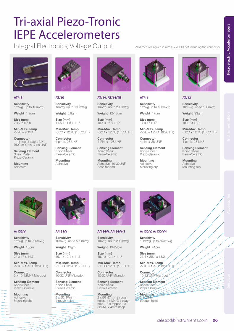
Tri-axial Piezo-Tronic IEPE AccelerometersIntegral Electronics, Voltage Output
AT/18
Sensitivity1mV/g up to 10mV/g
Weight 1.2gm
Size (mm) 7 x 7.5 x 5.6
Min-Max. Temp-50˚C • 200˚C
Connector 1m integral cable, 3 X BNC or 4 pin ¼-28 UNF
Sensing ElementShear Plate Piezo-Ceramic
MountingAdhesive
AT/10
Sensitivity1mV/g up to 100mV/g
Weight 6.9gm
Size (mm) 11.5 x 11.5 x 11.5
Min-Max. Temp-50˚C • 125˚C (185˚C HT)
Connector 4 pin ¼-28 UNF
Sensing ElementKonic Shear Piezo-Ceramic
MountingAdhesive
AT/14, AT/14/TB
Sensitivity1mV/g up to 200mV/g
Weight 12/18gm
Size (mm) 16.4 x 16.4 x 12
Min-Max. Temp-50˚C • 125˚C (185˚C HT)
Connector 4-Pin ¼ - 28 UNF
Sensing ElementKonic Shear Piezo-Ceramic
MountingAdhesive, 10-32UNF Base tapped.
AT/11
Sensitivity1mV/g up to 100mV/g
Weight 17gm
Size (mm) 17 x 17 x 17
Min-Max. Temp-50˚C • 125˚C (185˚C HT)
Connector 4 pin ¼-28 UNF
Sensing ElementKonic Shear Piezo-Ceramic
MountingAdhesiveMounting clip
AT/13
Sensitivity10mV/g up to 100mV/g
Weight 23gm
Size (mm) 19 x 19 x 19
Min-Max. Temp-50˚C • 125˚C (185˚C HT)
Connector 4 pin ¼-28 UNF
Sensing ElementKonic Shear Piezo-Ceramic
MountingAdhesiveMounting clip
A/136/V
Sensitivity1mV/g up to 200mV/g
Weight 18gm
Size (mm) 24 x 17 x 14.7
Min-Max. Temp-50˚C • 125˚C (185˚C HT)
Connector 3 x 10-32UNF Microdot
Sensing ElementKonic Shear Piezo-Ceramic
MountingAdhesiveMounting clip
A/131/V
Sensitivity10mV/g up to 500mV/g
Weight 19gm
Size (mm) 19.1 x 19.1 x 11.7
Min-Max. Temp-50˚C • 125˚C (185˚C HT)
Connector 10-32 UNF Microdot
Sensing ElementKonic Shear Piezo-Ceramic
Mounting2 x Ø3.57mmthrough holes
A/134/V, A/134/V-3
Sensitivity1mV/g up to 200mV/g
Weight 19/22gm
Size (mm) 19.1 x 19.1 x 11.7
Min-Max. Temp-50˚C • 125˚C (185˚C HT)
Connector 10-32 UNF Microdot
Sensing ElementKonic Shear Piezo-Ceramic
Mounting2 x Ø3.57mm throughholes, 1 x M4 Ø throughhole + 3 x tapped 10-32UNF x 4mm deep
A/130/V, A/130/V-1
Sensitivity10mV/g up to 500mV/g
Weight 41gm
Size (mm) 25.4 x 25.4 x 13.2
Min-Max. Temp-50˚C • 125˚C (185˚C HT)
Connector 10-32 UNF Microdot
Sensing ElementKonic Shear Piezo-Ceramic
Mounting3 x Ø3mmthrough holes
All dimensions given in mm (L x W x H) not including the connector

www.djbinstruments.com | 07
Piez
oele
ctri
c A
ccel
erom
eter
sIn
stru
men
tati
onA
cces
sori
esSe
rvic
es
Mono-axial Piezoelectric AccelerometersCharge Output
Micro-MiniatureA/28/E
Sensitivity0.4pC/g nom.
Weight 0.19gm
Size (mm) 5.1 x Ø3.1 x 2.1
Min-Max. Temp-50˚C • 200˚C
Connector Integral A/28/E-1L8 A/28/E
Sensing ElementShear Plate Piezo-Ceramic
MountingAdhesive
MiniatureA/25/E
Sensitivity2pC/g nom.
Weight 1.5gm
Size (mm) 10.8 x Ø6.4 x 5
Min-Max. Temp-50˚C • 200˚C
Connector L5
Sensing ElementKonic Shear Piezo-Ceramic
MountingAdhesive
MiniatureA/27/E
Sensitivity2pC/g nom.
Weight 1.8gm
Size (mm) 11.1 x 7.1 x 5.4
Min-Max. Temp-50˚C • 200˚C
Connector M3.5 KP
Sensing ElementKonic Shear Piezo-Ceramic
MountingAdhesive
MiniatureA/24/E, A/24/TE,A/24/TS
Sensitivity5pC/g nom.
Weight 2gm
Size (mm) 8 (A/F) x 9
Min-Max. Temp-50˚C • 200˚C
Connector M3.5 KP
Sensing ElementKonic Shear Piezo-Ceramic
MountingAdhesive,M4 x 5mm Integral stud
A/23/E, A/23/S,A/23/TE, A/23/TS
Sensitivity8pC/g nom.
Weight 3.6-4gm
Size (mm) 9.5 (A/F) x 10
Min-Max. Temp-50˚C • 250˚C
Connector 10-32 UNF Microdot
Sensing ElementKonic Shear Piezo-Ceramic
MountingAdhesive,M5 x 5mm Integral stud
A/22
Sensitivity26pC/g nom.
Weight 12gm
Size (mm) 17.2 x 16 x 8.1
Min-Max. Temp-50˚C • 250˚C
Connector 10-32UNF microdot
Sensing ElementKonic Shear Piezo-Ceramic
Mounting3.5mm through hole
A/20, A/20/T, A/20/TC
Sensitivity30pC/g nom.
Weight 12.5gm (A/20, A/20/T)27gm (A/20/TC)
Size (mm) 14.3 (A/F) x 16.6
Min-Max. Temp-50˚C • 250˚C
Connector 10-32 UNF Microdot, TNC
Sensing ElementKonic Shear Piezo-Ceramic
MountingBase tapped 10-32 UNFx 4mm deep
A/29, A/29/T, A/29/TC
Sensitivity100pC/g
Weight 46gm (A/29, A/29/T)51gm (A/29/TC)
Size (mm) 19.1 (A/F) x 21.8
Min-Max. Temp-50˚C • 250˚C
Connector 10-32 UNF Microdot, TNC
Sensing ElementKonic Shear Piezo-Ceramic
MountingBase tapped 10-32 UNFx 4mm deep
A/21, A/21/T, A/21/TC
Sensitivity360pC/g nom.
Weight 95gm (A/21, A/21/T)102gm (A/21/TC)
Size (mm) 25.4 (A/F) x 19.1
Min-Max. Temp-50˚C • 250˚C
Connector 10-32 UNF Microdot, TNC
Sensing ElementKonic Shear Piezo-Ceramic
MountingBase tapped 10-32 UNFx 4mm deep
A/600, A/600/T
Sensitivity1.2nC/g nom.
Weight 115gm
Size (mm) 28 (A/F) x 28
Min-Max. Temp-50˚C • 250˚C
Connector 10-32 UNF Microdot
Sensing ElementKonic Shear Piezo-Ceramic
MountingBase tapped 10-32 UNFx 4mm deep
All dimensions given in mm (L x W x H) not including the connector

[email protected] | 08
Piez
oele
ctri
c A
ccel
erom
eter
sIn
stru
men
tati
onA
cces
sori
esSe
rvic
es
Tri-axial Piezoelectric AccelerometersCharge Output
AT/08
Sensitivity0.4pC/g nom.
Weight 1.2gm
Size (mm) 7 x 7.5 x 5.6
Min-Max. Temp-50˚C • 200˚C
Connector 1m integral cable, 3 X BNC or 4 pin ¼-28 UNF
Sensing ElementShear Plate Piezo-Ceramic
MountingAdhesive
AT/01
Sensitivity2pC/g nom.
Weight 6.8gm
Size (mm) 11.4 x 11.4 x 12.1
Min-Max. Temp-50˚C • 200˚C
Connector 4 pin ¼-28 UNF
Sensing ElementKonic Shear Piezo-Ceramic
MountingAdhesive
AT/04, AT/04/TB
Sensitivity5pC/g nom.
Weight 11.5-18gm
Size (mm) 16.4 x 16.4 x 12.1
Min-Max. Temp-50˚C • 200˚C
Connector 4 pin ¼-28UNF
Sensing ElementKonic Shear Piezo-Ceramic
MountingAdhesive, 10-32UNF Base tapped
A/38, A/38-1
Sensitivity0.4pC/g nom.
Weight 0.9gm
Size (mm) 7.3 x 7.3 x 4.4
Min-Max. Temp-50˚C • 200˚C
Connector L8
Sensing ElementShear Plate Piezo-Ceramic
Mounting1 x Ø 2.1mmthrough hole,Adhesive
A/31
Sensitivity7pC/g nom.
Weight 18gm
Size (mm) 19.1 x 19.1 x 11.7
Min-Max. Temp-50˚C • 220˚C
Connector 10-32 UNF Microdot
Sensing ElementKonic Shear Piezo-Ceramic
Mounting2 x Ø3.25mm through holes
A/34, A/34-2
Sensitivity7pC/g nom.
Weight 19/22gm
Size (mm) 19.1 x 19.1 x 11.7
Min-Max. Temp-50˚C • 220˚C
Connector 10-32 UNF Microdot
Sensing ElementKonic Shear Piezo-Ceramic
Mounting2 x Ø3.25mm through hole. 1 x M4 Ø through hole. 3 x tapped 10-32 UNF x 4mm deep
A/30, A/30-1
Sensitivity25pC/g nom.
Weight 38gm
Size (mm) 25.4 x 25.4 x 13.2
Min-Max. Temp-50˚C • 220˚C
Connector 10-32 UNF Microdot
Sensing ElementKonic Shear Piezo-Ceramic
Mounting3 x Ø 3mm through holes; 1 x M4 Ø through hole. 3 x tapped 10-32 UNF x 4mm deep
A/36, A/36-1
Sensitivity5pC/g
Weight 18gm
Size (mm) 24 x 17 x 10.7
Min-Max. Temp-50˚C • 220˚C
Connector 10-32 UNF Microdot
Sensing ElementKonic Shear Piezo-Ceramic
MountingAdhesive, Mounting clip,3 x mounting holes
IEPE & Charge Accelerometers – Pros and Cons
IEPE: Pros• Use wide range of cable types • Less sensitive to dirt• Signal power often built into DAQ systems
IEPE: Cons• Lower operating temperature• More expensive per unit• Fixed sensitivity• Less robust
Charge: Pros• Higher operating temperature • Robust• Flexible sensitivity via charge amplifier• Lower cost per unit Charge: Cons• Must use low noise cable type• Sensitive to dirt on connectors• Sensitive to cable flex• Requires charge amplifier
All dimensions given in mm (L x W x H) not including the connector

www.djbinstruments.com | 09
Piez
oele
ctri
c A
ccel
erom
eter
sIn
stru
men
tati
onA
cces
sori
esSe
rvic
es
Water Cooled Tri-Axial Piezoelecric A/33, A/33-1
Sensitivity 7pC/g nom.
Weight 38gm
Size (mm) 28 x 28 x 19
Min-Max. Temp -50˚C • 900˚C Max Surface Temp with Water Flow
Connector 10-32 UNF Microdot
Sensing ElementKonic Shear Piezo-Ceramic
Mounting1 x Ø5.5mm through hole
Mono-axial Seismic Accelerometers
Charge output micro g measurement A/800, A/800/T, A/800/TC
Sensitivity 9nC/g nom.
Weight 400gm (A/800, A/800/T) 407gm (A/800/TC)
Size (mm) 38.1 (A/F) x 44
Min-Max. Temp -50˚C • 250˚C
Connector 10-32 UNF Microdot, TNC
Sensing ElementShear Plate Piezo-Ceramic
Mounting
IEPE micro g measurement A/1800/V, A/1800/VT, A/1800/VTC
Sensitivity 10V/g
Weight 400gm (A/1800, A/1800/VT) 407gm (A/1800/VTC)
Size (mm) 38.1 (A/F) x 44
Min-Max. Temp -50˚C • 125˚C
Connector 10-32 UNF Microdot, TNC
Sensing ElementShear Plate Piezo-Ceramic
Mounting
Water Cooled IEPE Tri-AxialA/133/V
Sensitivity 1mV/g up to 250mV/g
Weight 38gm
Size (mm) 28 x 28 x 19
Min-Max. Temp -50˚C • 900˚C Max Surface Temp with Water Flow
Connector 10-32 UNF Microdot
Sensing ElementKonic Shear Piezo-Ceramic
Mounting1 x Ø5.5mm through hole
Ultra High Temperature Exhaust & Turbo Charger Test Accels, 900°C
Seismic Accelerometers... are generally much bigger and heavier than other test and measurement accelerometers. This is due to the much higher quantity of piezoelectric material and the large mass material required to create the high output (typically 10V/g or 9000pC/g) which allows for micro ‘g’ measurements. They are also limited on their higher frequency capability, usually limited to 500Hz to 1kHz. With a typical peak measurement range of just 0.5g their use is restricted to typical seismic applications.
Water Cooled Triaxial Accelerometers A unique device specifically developed for exhaust and turbo charger testing where surface temperatures can exceed 900°C. As the only fully integrated device on the market it offers unrivalled reliability and repeatability under the most extreme conditions. Using a simple water pump (usually a car windscreen washer pump) requiring just 0.5ltr/min flow the operation is both simple and effective. With no reduction in operating temperature, even using the IEPE voltage output version, DJB lead the world in this application.
All dimensions given in mm (L x W x H) not including the connector

[email protected] | 10
Piez
oele
ctri
c A
ccel
erom
eter
sIn
stru
men
tati
onA
cces
sori
esSe
rvic
es
Mono-axial Industrial Piezoelectric AccelerometersCharge Output
A/53/F, A/53/F/HT
Sensitivity 12pC/g (A/53/F), 1.7pC/g nom. (A/53/F/HT)
Weight 20gm (exc cable)
Size (mm) 33 x 13.7 x 14.2
Max. Temp 260˚C (A/53/F)400˚C (A/53/F/HT)
Connector 7/16 UNS HT Microdot
Cable Integral Hardline Cable
Mounting 2 x Ø5.2mm holes @ 24.4mm ctrs.
A/52/F, A/52/F/HT
Sensitivity 100pC/g (A/52/F), 12pC/g nom. (A/52/F/HT)
Weight 100gm (exc cable) (A52/F)123gm (exc cable) (A/52/F/HT)
Size (mm) 50.8 x 29.6 x 21.7
Max. Temp 260˚C (A/52/F)400˚C (A/52/F/HT)
Connector 7/16 UNS HT Microdot
Cable Integral Hardline Cable
Mounting 2 x Ø6.4mm holes @ 38.1mm ctrs.
A/81/F, A/81/F/HT
Sensitivity 230pC/g (A/81/F), 35pC/g nom. (A/81/F/HT)
Weight 150gm (exc cable) (A/81/F)160gm (exc cable) (A/81/F/HT)
Size (mm) 50.8 x 29.6 x 24.6
Max. Temp 260˚C (A/81/F)400˚C (A/81/F/HT)
Connector 7/16 UNS HT Microdot
Cable Integral Hardline Cable
Mounting 2 x Ø6.4mm holes @ 38.1mm ctrs.
A/301/F, A/301/F/HT
Sensitivity 220pC/g (A/301/F) 25pC/g nom. (A/301/F/HT)
Weight 150gm (A301/F, A/301/F/HT)
Size (mm) 31.5 x 31.5 x 25.4
Max. Temp 260˚C (A/301/F)400˚C (A/301/F/HT)
Connector 2 pole connector 7/16 UNS
Mounting 4 x Ø3.8mm holes 24.7mm PCD
Charge Output Voltage Output
A/107/F, A/107/F/HT
Sensitivity 100pC/g (A/107/F)10pC/g (A/107/F/HT)
Weight 80gm
Size (mm) 29.2 x 29.2 x 24.5
Max. Temp 260˚C (A/107/F) 400˚C (A/107/F/HT)
Connector 2 pole connector 7/16 UNS
Mounting 3 x Ø3.2mm holes 25.4mm PCD. F1- 30.2mm PCD
A/1107/V
Sensitivity 100mV/g
Weight 85gm
Size (mm) 29.2 x 29.1 x 24.5
Max. Temp 185˚C
Connector 2 pole connector 7/16 UNS
Mounting 3 x Ø4.7mm holes30.2mm PCD
A/172/VF
Sensitivity 100mV/g
Weight 130gm
Size (mm) 40.2 x 36.4 x 24.7
Max. Temp 185˚C
Connector 2 pole connector 7/16 UNS
Mounting 3 x Ø5mm holes34.29mm PCD
All dimensions given in mm (L x W x H) not including the connector

www.djbinstruments.com | 11
Piez
oele
ctri
c A
ccel
erom
eter
sIn
stru
men
tati
onA
cces
sori
esSe
rvic
es
Piezoelectric Dynamic Pressure Transducers
M/02/FA, M/02/TA
Sensitivity 5nC/bar nom.
Weight 56.5gm (FA) 77gm (TA)
Size (mm) 36 (FA) 42 (TA)
Min-Max. Temp -50˚C • 250˚C
Max Wkg. Pressure 200 bar
Deviation-5% @ -50°C+15% @ +250°C
Connector 10-32 UNF Microdot skt
Case Seal Welded, hermetic diaphragm
Accelerometer Specifications ExplainedConstantcurrentsupply – 2-20mA, supply voltage 15-35V DC. This is the range of supply voltage/currents that the IEPE accelerometer will operate with, this should allow it to work with a wide variety of off the shelf data acquisition systems.
Settlingtime – This is the time taken for the IEPE accelerometer’s internal electronics to settle to its bias voltage and reach its operating condition.
Sensitivity – Either rated in pC/g for charge output accels or mV/g for IEPE accels this is the output signal you can expect for a given acceleration.
Crossaxiserror– A critical parameter when recalibrating accelerometers. The cross axis error relates to the percentage of the output measured in the primary axis of vibration which is actually due to vibration applied to the accelerometer from a cross axial direction. Typically less than 5% this parameter should always be checked at recalibration. DJB’s Konic Shear design is one of the best at minimising cross axis effects due to its radial design.
BiasVoltage – Only relevant to IEPE accels, this reflects the operating DC voltage that the integral electronics amplifier circuit operates at when powered. This will vary from one manufacturer to another and higher is not necessarily better than lower, the level is simply a feature of the electronics design.
SaturationLimit – Peak measuring range of the accelerometer.Base strain/Base bending – is the phenomena whereby an additional strain is applied to the piezoelectric sensing element due to the bending of the base of the accelerometer caused by a bending mode in the test item. This is not part of the vibration measurement and as such is an error. This is a common fault with compressive accelerometer designs, but less so with shear and Konic shear designs. This should be less than 5%.
M/02/F, M/02/T
Sensitivity 5nC/bar nom.
Weight 46gm (F) 70gm (T)
Size (mm) 23 (F) 33.5 (T)
Min-Max. Temp -50˚C • 250˚C
Max Wkg. Pressure 200 bar
Deviation -5% @ -50°C+15% @ +250°C
Connector 10-32 UNF Microdot skt
Case Seal Welded, hermetic diaphragm
A/140
Sensitivity100mV/g
Weight 76gm
Size (mm) Ø22 x 58
Min-Max. Temp-50˚C • 120˚C
Connector 2-Pin MIL-C-5015
Mounting¼-28 UNF Base tapped
A/140/S
Sensitivity100mV/g
Weight 81gm
Size (mm) 37 x 24.9 x 25.4
Min-Max. Temp-50˚C • 120˚C
Connector 2-Pin MIL-C-5015
Mounting¼-28 UNF through hole
A/140/C
Sensitivity100mV/g
Weight 76gm
Size (mm) Ø22 x 44
Min-Max. Temp-50˚C • 140˚C
Connector Integral Overbraided Stainless Steel Cable
Mounting¼-28 UNF Base tapped
Low CostMono-axial Industrial IEPE Accelerometers
All dimensions given in mm (L x W x H) not including the connector

[email protected] | 12
Inst
rum
enta
tion
Piez
oele
ctri
c A
ccel
erom
eter
sA
cces
sori
esSe
rvic
es
Instrumentation
Instrumentation - Points to consider• ChargeorIEPE – If you are using a charge accelerometer you
will need a charge amplifier. Very few data acquisition systems offer built in charge conditioning so an external box will be required. IEPE accelerometers can often be connected directly to the acquisition system as the IEPE power is available, an ideal way of minimising hardware needs. If an older acquisition system is used, a range of IEPE signal conditioners is available from battery powered/DC supplied to rack Base multi channel solutions. See pages 15/17 for more details.
• In line Charge Amplifier – This is becoming a very popular way of connecting charge accelerometers, utilising the IEPE power built into many data acquisition systems. The fixed gain amplifier is housed in a BNC/microdot adaptor, allowing it to be connected directly to the data acquisition hardware with a low noise cable attached to a charge accelerometer – see page 16 for more details.
• Filters – Analogue filters enable users to filter out unwanted noise or other spurious signals. See page 16.
• Integrators – Conversion of the accelerometer signal to either a velocity or displacement value is a relatively simple mathematical process. Integrators can do this in real time allowing the use of the already converted signal. See page 16.
DJB Instrumentation is available as modular systems in portable case or rack based systems as well as fixed, single or 9 channel solutions.
A/140/C
Sensitivity100mV/g
Weight 76gm
Size (mm) Ø22 x 44
Min-Max. Temp-50˚C • 140˚C
Connector Integral Overbraided Stainless Steel Cable
Mounting¼-28 UNF Base tapped
Low CostMono-axial Industrial IEPE Accelerometers

www.djbinstruments.com | 13
Inst
rum
enta
tion
Piez
oele
ctri
c A
ccel
erom
eter
sA
cces
sori
esSe
rvic
es
IEPE Instrumented Impact Hammer Range
IH-01
Sensitivity 25mV/N
Measuring Range 200N
Hammer Mass 180gm
Head Diameter 21mm
Hammer Length 250mm
Output Connector BNC
Tips Supplied Stainless Steel, Aluminium, Nylon, Rubber
IH-02
Sensitivity 2.5mV/N
Measuring Range 2000N
Hammer Mass 180gm
Head Diameter 16mm
Hammer Length 250mm
Output Connector BNC
Tips Supplied Stainless Steel, Aluminium, Nylon, Rubber
IH-05
Sensitivity 1mV/N
Measuring Range 5000N
Hammer Mass 220gm
Head Diameter 20mm
Hammer Length 250mm
Output Connector BNC
Tips Supplied Stainless Steel, Aluminium, Nylon, Rubber
IH-10
Sensitivity 0.5mV/N
Measuring Range 10000N
Hammer Mass 1400gm
Head Diameter 45mm
Hammer Length 395mm
Output Connector BNC
Tips Supplied Hard tip, Medium tip, Soft tip
IH-50
Sensitivity 0.1mV/N
Measuring Range 50000N
Hammer Mass 1900gm
Head Diameter 45mm
Hammer Length 395mm
Output Connector BNC
Tips Supplied Hard tip, Medium tip, Soft tip
Use of Modal / Impact HammersThe IH series IEPE Impact Hammer range features a rugged force sensor that is integrated into the hammer’s striking surface. The force sensor serves to provide a measurement of the amplitude of the energy stimulus that is imparted to a test object. A variety of tips supplied with each hammer permit the energy content of the force impulse to be tailored to suit the requirements of the item under test. Using multi-channel data acquisition and analysis software, the test engineer is able to ascertain a variety of mechanical properties leading to an understanding of an object’s structural behaviour. Items analysed can include resonance detection, mode shapes, transfer characteristics, and structural health, such as crack and fatigue detection.
IH series Impact Hammers can be applied for Structure Health Testing, Resonance Determination, Modal Analysis etc. Used in association with DJB’s wide range of accelerometers full response data can be captured during impact testing.
All dimensions given in mm (L x W x H) not including the connector
Excitation pulse width and frequency response vary with hammerhead materials. Response curves are for indication only
[email protected] | 14
Inst
rum
enta
tion
Piez
oele
ctri
c A
ccel
erom
eter
sA
cces
sori
esSe
rvic
es
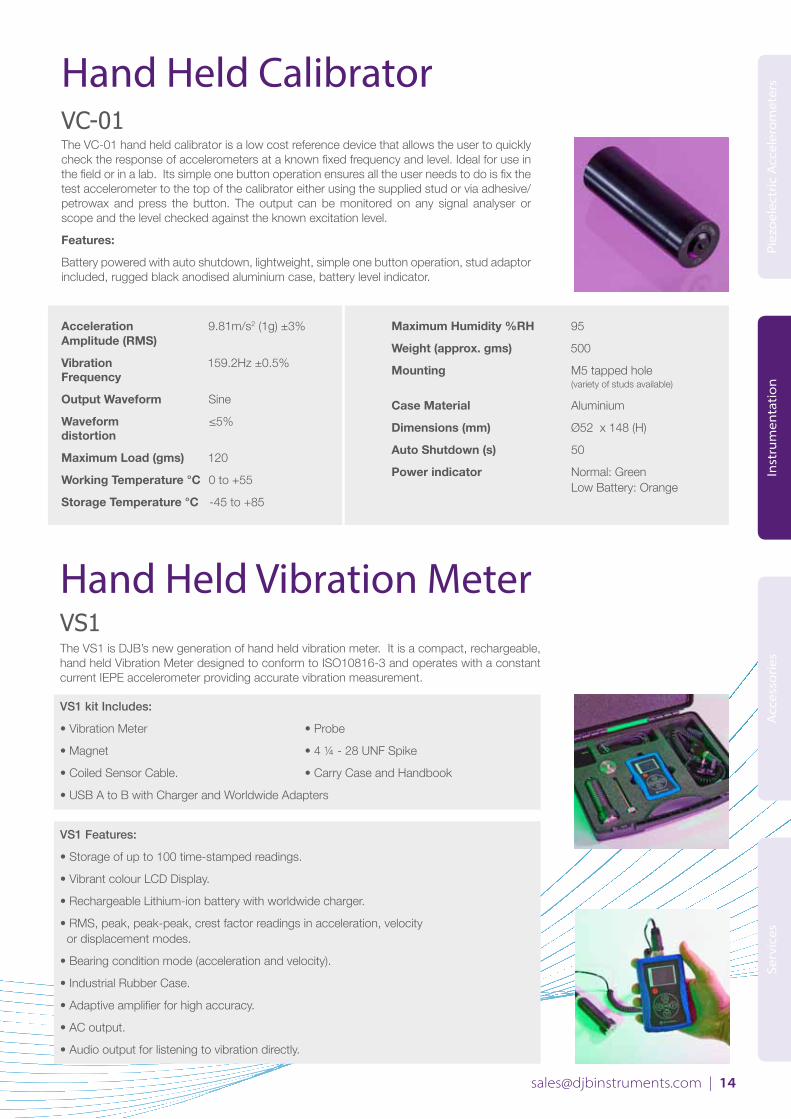
VC-01The VC-01 hand held calibrator is a low cost reference device that allows the user to quickly check the response of accelerometers at a known fixed frequency and level. Ideal for use in the field or in a lab. Its simple one button operation ensures all the user needs to do is fix the test accelerometer to the top of the calibrator either using the supplied stud or via adhesive/petrowax and press the button. The output can be monitored on any signal analyser or scope and the level checked against the known excitation level.
Features:
Battery powered with auto shutdown, lightweight, simple one button operation, stud adaptor included, rugged black anodised aluminium case, battery level indicator.
Hand Held Calibrator
VS1The VS1 is DJB’s new generation of hand held vibration meter. It is a compact, rechargeable, hand held Vibration Meter designed to conform to ISO10816-3 and operates with a constant current IEPE accelerometer providing accurate vibration measurement.
VS1 kit Includes:
• Vibration Meter • Probe
• Magnet • 4 ¼ - 28 UNF Spike
• Coiled Sensor Cable. • Carry Case and Handbook
• USB A to B with Charger and Worldwide Adapters
VS1 Features:
• Storage of up to 100 time-stamped readings.
• Vibrant colour LCD Display.
• Rechargeable Lithium-ion battery with worldwide charger.
• RMS, peak, peak-peak, crest factor readings in acceleration, velocity or displacement modes.
• Bearing condition mode (acceleration and velocity).
• Industrial Rubber Case.
• Adaptive amplifier for high accuracy.
• AC output.
• Audio output for listening to vibration directly.
Hand Held Vibration Meter
Acceleration 9.81m/s2 (1g) ±3% Amplitude (RMS)
Vibration 159.2Hz ±0.5%Frequency
Output Waveform Sine
Waveform ≤5%distortion
Maximum Load (gms) 120
Working Temperature °C 0 to +55
Storage Temperature °C -45 to +85
Maximum Humidity %RH 95
Weight (approx. gms) 500
Mounting M5 tapped hole (variety of studs available)
Case Material Aluminium
Dimensions (mm) Ø52 x 148 (H)
Auto Shutdown (s) 50
Power indicator Normal: Green Low Battery: Orange

www.djbinstruments.com | 15
Inst
rum
enta
tion
Piez
oele
ctri
c A
ccel
erom
eter
sA
cces
sori
esSe
rvic
es
Source Amplifiers
CA/04/V(Velocity)
Frequencyn/a
Output O/Ps 100mV/g& 1V/mm/sec. (max)
Input range 1/110pC/g
Bandwidth0.7/100kHz
Warning indicatorsn/a
CA/04/D(Differential)
Frequencyn/a
Output n/a
Input range 1/110pC/g (CA/04/D) 10/1100pC/g (CA/04/DH)
Bandwidth0.7/100kHz
Warning indicatorsn/a
9 Channel Charge or Voltage or Combined Source Amplifier CV9-C/CV9-V/CV9-CV
Input connectors 9 x BNC
Output connectors9 x BNC
Sensor Excitation (V & CV only) +24VDC, 2-14mA user selectable
Gain x1, x10, x100 selectable per channel
Bandwidth0.5/500kHz Max.
Warning indicators Open/short circuit
VV/04
Output Normalised O/P31.6V/g (max)DC O/P
Input range 1/110mV/g
Bandwidth3dB Bandwidth0.4Hz/100kHz
Warning indicatorsTransducer O/C andS/C Fault detection
3 Channel VoltageSource AmplifierV3/04
Output AC & DC O/P
Gain factor x 1, 3.16, 10, 31.6and 100
Output Connector n/a
Input Connector n/a
Warning indicatorsTransducer O/C andS/C Fault detectionO/L Indicator
4 Channel VoltageSource AmplifierV4/04
Output AC & DC O/P
Gain factor x 1, 3.16, 10, 31.6and 100
Output Connector n/a
Input Connector n/a
Warning indicatorsTransducer O/C andS/C Fault detectionO/L Indicator
Battery IEPE Voltage SupplyVB/01
Output Unity Gain
Output Connector BNC
Input Connector BNC
Warning indicatorsTransducer O/C and S/C detectionPower on
Voltage Level Alarm
CA/04/N, CA/04/NL,CA/04/NH, CA/04/EH
FrequencyExtended Low Frequency Response
Output Normalised O/P 3.16V/g (max) DC O/P
Input range 1/110pC/g (CA/04/N)0.1/11pC/g (CA/04/NL) 10/1100pC/g (CA/04/NH)100/11000pC/g (CA/04/EH)
Bandwidth0.1/100kHz
Warning indicatorsOverload LED
DIN Rail Mounted Charge or Voltage Source AmplifierCV1-C, CV1-V
Output Fixed gain selectable on request
Output Connector Terminal Block
Input Connector SMC
Warning indicatorsPower on
Please note:Other options including filters are available on our website.
All dimensions given in mm (L x W x H) not including the connector
Charge Charge & Voltage
Level AlarmLA/04
FeaturesHigh level alarm indicator Alarm timer eliminates spurious triggering, Programmable alarm Setpoint and timer, Latching non-latching alarm mode
Input

[email protected] | 16
Inst
rum
enta
tion
Piez
oele
ctri
c A
ccel
erom
eter
sA
cces
sori
esSe
rvic
es
Inline Converters Integrators
Hybrid ChargeAmplifierCA/100/F
Voltage+10/+30
Connector I/P 5PO/P 10-32 UNF Microdot
Gain 1mV/pC to 1V/pC
Hybrid Two Wire Voltage Source Line DriverQV/01
VoltageMiniature 2 Wire Charge/Voltage Converter
Connector I/P 10-32 UNF MicrodotO/P 10-32 UNF Microdot
Gain 1mV/pC to 1V/pC
Hybrid Two Wire Voltage Source Line DriverQV/02
VoltageMiniature 2 Wire Charge/Voltage Converter
Connector I/P 10-32 UNF MicrodotO/P BNC
Gain1 and 10mV/pC
Acceleration/ Velocity ConverterVM/04
VoltageSingle Integrator/ High Pass Filter Converts Vibration Data from Acceleration to Velocity Format
Output Configurable for optimum signal/ noise down to min. 2Hz
Acceleration/ Displacement ConverterDM/04
VoltageDouble Integrator/ High Pass Filter Converts Vibration Data from Acceleration to Displacement Format
Output Configurable for optimum signal/noise down to min. 2Hz
Bandpass FilterBP/04/NBP/04/W
FrequenciesFixed Frequency Bandpass Filters 1Hz/15kHz Tuning Rate
High PassCustomer Selectable
Low Pass Customer Selectable
DIN Rail Mounted Filter ModuleCV1-F CV1-VF
FrequenciesFixed Frequency factory set to customer spec. Variable Frequency set by DIP switch, 255 steps
High PassRange of High pass filters available
Low Pass Range of Low pass filters available
Filters LHP Filter
Available as a single channel DC powered unit or up to 9 channels in a AC/DC powered chassis. Utilising simple BNC input and output connectors on the front panel, with user selectable AC/DC coupling and IEPE signal source (4mA/20VDC).For more details visit our website.
Features:• Input Overload Indicator• Frequencies: Full range of
filter responses available, Butterworth, Bessel, anti-alias & general purpose
• Switchable High/Low Pass• Single ended/differential input• Modular System• 6 Gain steps to x50
Modular Switchable Low/High Pass Filter
All dimensions given in mm (L x W x H) not including the connector

Inst
rum
enta
tion
Piez
oele
ctri
c A
ccel
erom
eter
s
www.djbinstruments.com | 17
Acc
esso
ries
Serv
ices
DJB’s range of modular instrumentation can be supplied in portable and rack base housings suited for use with any of the 04 range of instrumentation modules seen on pages 15/16/17.
PC/04 - Portable housings with up to 12 single width slots are available with user selectable input and output connectors, usually microdot or BNC. Housings also include power supply, module interconnections for a wide range of module combinations. Power options include standard AC power in addition to DC 12/28VDC.
SR/04 - Rack based solutions are available with 200/240VAC, 90/130VAC 50/60Hz mains input, ±15V, 1.5A max. O/P regulated power supply.
For input/output connector options contact our sales team [email protected]
Portable and Rack Based Housings
As an alternative to the modular solution, DJB also offer a range of 9 Channel rack based Amplifiers, the CV9 range is available in three versions, all offering simple front panel BNC input and output connectors and all available as AC or DC powered racks.
CV9-C is a fixed 9 channel charge amplifier with individually selectable gain on each channel via a three way switch x1, x10, x100 gain.
CV9-V is a fixed 9 channel IEPE supply with individually selectable gain on each channel via a three way switch x1. X10, x100 gain, also featuring an indicator lamp for open/correct circuit connection per channel.
CV9-CV is a fixed 9 channel Charge/IEPE supply amplifier with all the features of the other models in addition to individually selectable charge/IEPE per channel.
9 Channel Charge, Voltage or Combined Source Amplifier
Features
• Short Circuit/open circuit warning indicator
• IEPE Constant Current Source, user selectable via internal jumpers
• Switchable Gain of x1, x10 and x100 for charge and voltage inputs, individual channel selectable
• Front Panel BNC input/output connectors
• 19” Rack Mountable Enclosure
Power
Input Connector IEC 320
Input 105-240 VAC (switchable)
Status LED Power Indicator on Front Panel
Physical
Weight 2.75kg
Size H 44.5mm, W 482.6mm, D 348mm

[email protected] | [email protected] | 18
Inst
rum
enta
tion
Piez
oele
ctri
c A
ccel
erom
eter
sA
cces
sori
esSe
rvic
es
Mounting Guide
Accelerometer Mounting is a critical part of the testing process and one that is most commonly overlooked having little attention paid to it. To maximise data accuracy the accelerometer must be closely coupled with the test item and a poor mounting method can introduce significant errors into the data, particularly as frequency levels rise. A summary of the mounting methods is outlined below:
StudMount This is the best and most effective method of mounting an accelerometer. However, there is a need to drill holes in your test item which is not always possible. Stud mounting will give the best frequency response at high levels and to improve coupling a small amount of silicone spray can be used on the test surface prior to mounting the accelerometer. Always use the manufacturers recommended mounting torque when tightening the accelerometer.
AdhesiveMountThis is probably the second most commonly used mounting method, however it is also the one that can cause the most problems. It is essential that a minimum amount of adhesive is used, too much and it can cause damping to the vibration transmission. Cyanoacrylate is an excellent adhesive for this application due to its thin consistency. When removing an accelerometer that has been stuck down DO NOT knock it off sideways. It should be twisted off using a spanner or removal tool. Always remove
old adhesive before refitting an accelerometer and in doing so try not to damage the base of the accelerometer.
PetrowaxPetroleum based wax is a great way of carrying out Modal testing and other quick ‘look see’ type tests due to the ease of removal and refitting. However, it should only be used for relatively low frequency testing and as with adhesive, a minimal amount of wax should be used due to the potential for damping to occur. Petrowax should only be used at ambient conditions as temperature will render the wax useless. Sliding the accelerometer into place with the wax on the base creates a good bond and removes excess wax.
MagneticMountsMagnetic mounts can offer quite high frequency responses but are obviously only appropriate for test items with magnetic surfaces and are more often used for machine monitoring applications. Magnets used are generally of high pull force and as such can damage surfaces if not used appropriately.
ClipMountsClips can be used for low frequency testing such as Modal analysis and are an ideal way of installing triaxial accelerometers in such a way as to make their X,Y,Z axes line up regardless of their mounting orientation. This also means clips can be left in place which makes repeating of the test easier.
Cables andAccessories

www.djbinstruments.com | 19
Piez
oele
ctri
c A
ccel
erom
eter
sIn
stru
men
tati
onA
cces
sori
esSe
rvic
es
AccessoriesConnectors
Product Code4P-1 4S 4S-1 7P7S BC FC103 KP KP5L8 LP5 LP7 LP8 M2
M5
Description¼-28 UNF 4 pin connector plugM4.5mm, 4 pin connector socket¼-28 UNF 4 pin connector socket2 pole 7/16 UNS free plug2 pole 7/16 UNS free socketBNC PlugFischer 6 pole Series 103 connectorM3.5 Mini-Microdot Plug5-44UNC Mini-microdot PlugConnector for A/28/ELemo 5 pin PlugLemo 7 pin PlugLemo 8 pin PlugMicrodot Plug for 2.5mm tri-ax hardline cable - high tempM5 Microdot Plug
Product CodeMPME MIL-C-5015 MPS MR MS SMBSMB-2SMBS SMC SS SSMC TC TCHBTPTS
Description10-32UNF Microdot PlugEnvironmental sealed 10-32 UNF Microdot Plug2 pole connector10-32UNF Microdot Plug sealed IP64Right-Angled 10-32UNF Microdot Plug10-32UNF Microdot SocketSMB connectorSMB Clamp ConnectorSMB Crimp Plug fitted to 2.8mm cableSMC Crimp PlugSealed Flanged 10-32UNF Microdot Plug IP64Sub Miniature SMC connectorTNC Clamp PlugTNC Clamp Plug with heatshrink bootLemo Mini Twin PlugTNC Socket Clamp
CablesSoftline Low Noise Cable for use with Charge or IEPE accelerometers/sensors
Cable CodeT08 T10 T18 T23P30 P31 P39 P45 P52
Description PFA Jacket - coaxial screenedFEP Jacket - coaxial screenedPFA Jacket - coaxial screenedPTFE Jacket - screened twin coreFEP Jacket - coaxial double screenedPVC Jacket - coaxial screenedPVC Jacket - coaxial extendable coilPVC Jacket - coaxial screenedPVC Jacket - screened twin core
O/D 0.8mm1.0mm1.8mm2.3mm3.0mm 3.0mm3.9mm4.5mm4.5mm
Softline Non-low Noise Cable for use with IEPE accelerometers/sensors
Cable CodeS18S28S30S51SC42
Softline 4 Core Cable
Cable CodeLT17ET25SM35
DescriptionFPA Jacket - 3 core low noise screenedFEP Jacket - 4 core screenedPVC Jacket - 4 core screened
O/D0.8mm2.5mm3.5mm
DescriptionFEP Jacket - coaxial screenedPVC Jacket - coaxial screenedFEP Jacket - coaxial double screenedPVC Jacket - coaxial screenedStainless Steel overbraided screened twin core
O/D1.8mm2.8mm3.0mm5.0mm 4.2mm
Hardline high temperature cable - Stainless Steel jacket with Mineral Insulation
Cable CodeHL15HL30HL25
DescriptionStainless Steel Mineral Insulated - twin coreStainless Steel Mineral Insulated - twin coreStainless Steel Mineral Insulated - triaxial
O/D1.5mm3.0mm2.5mm
Cable SelectionThe difference between Low noiseandNon-Lownoisecables…It is important to use the correct cable when using accelerometers.
Charge accelerometers - A charge output accelerometer must be used with a LOW NOISE cable. The term low noise refers to the cables ability to reduce triboelectric noise (otherwise known as motion induced noise) rather than electrical noise. This reduction is accomplished by the inclusion of a graphite or silver wrap on the outer surface of the inner dielectric layer. If a non low noise cable is used movement of the cable will add an additional signal into the data causing errors in data analysis.
IEPE accelerometers – An IEPE accelerometer is much more forgiving and can be used with almost any type of cable. The more traditional coaxial cable is commonly used for these accelerometers. If using both Charge and IEPE accelerometers within your facility. It is best to standardise all cables to be low noise types to avoid potential errors in using the wrong cable.
For more details about cable selection and for a practical demonstration of triboelectric noise please visit our Youtube page.
Max Temp200˚C200˚C260˚C260˚C200˚C85˚C80˚C85˚C60˚C
Max Temp260˚C200˚C80˚C
Max Temp200˚C70˚C200˚C80˚C120˚C
Max Temp800˚C800˚C800˚C

[email protected] | 20
Piez
oele
ctri
c A
ccel
erom
eter
sIn
stru
men
tati
onA
cces
sori
esSe
rvic
es
AccessoriesNon Isolated Mounting Studs/Bases
Product CodeSF/01 SF/02 SF/03 SP/01 SP/02 SP/03 SP/04 SA/03 SA/04
DescriptionFlat adhesive base, 22.2mm diameter, 5.8mm x ¼-28UNF thread Flat adhesive base, 12mm diameter, 3.7mm x 10-32UNF thread Flat adhesive base, 15.9mm diameter, 3.3mm x 10-32UNF thread Mounting stud, 4.2mm ¼-28UNF / 12.7mm ¼-28UNF thread Mounting stud, 2.7mm 10-32UNF / 9.7mm 10-32UNF thread Mounting stud 2.7mm 10-32UNF / 5.0mm M5 thread Mounting stud 2.7mm 10-32UNF / 5.0mm M6 threadAdhesive base for A/123/S & A/123/TS Adhesive base for A/124/TS
Isolated Mounting Studs/Bases
Product CodeIS/01IS/02IS/03IS/04IS/05SI/03 SI/05 SI/08 SI/09 SI/10 SI/11 SI/14 SI/22 CL/01
DescriptionFlanged Mounting Stud, 2.8mm 10-32UNF / 5.0mm 10-32UNF thread Flanged Mounting Stud, 2.8mm 10-32UNF / 5.0mm M5 thread Flanged Mounting Stud, 3.7mm 10-32UNF / 5.0mm 10-32UNF thread Flanged Mounting Stud, 3.7mm 10-32UNF / 5.0mm M5 thread Flanged Mounting Stud, 4.1mm ¼-28UNF / 5.0mm ¼-28UNF thread Flanged Mounting Stud, 3.7mm 10-32UNF / 14.5mm 10-32UNF thread Flanged Mounting Stud, 2.8mm 10-32UNF / 5.0mm 10-32UNF thread Flanged Mounting Stud, 3.7mm 10-32UNF / 5.0mm M5 thread Flanged Mounting Stud, 3.7mm 10-32UNF / 9.5mm M5 thread Flanged Mounting Stud, 3.7mm 10-32UNF / 9.5mm M6 thread Flanged Mounting Stud, 10-32 UNF Flanged Mounting Stud10-32 UNF/M5 Stud Kit for A/22 inc within the A/22AT/13 clip (bag of 50 MOQ)
Isolated Mounting Magnets
Product CodeIM/01IM/02SM/01SM/02SM/03SM/04
Description20.6mm A/F, 3.7mm 10-32UNF stud 20.6mm A/F, 10-32UNF tapped hole Adaptor stud for use with IM/02, 10-32 UNF / 5-40 UNC Adaptor stud for use with IM/02, 10-32UNF / ¼-28UNF Adaptor stud for use with IM/02, 10-32UNF / M6 Adaptor stud for use with IM/02, 10-32UNF / 10-32UNF
Triaxial Mounting Blocks
Product CodeFB1
FB2
Petrowax
DescriptionStainless Steel 10-32UNF tapped on 5 faces, supplied with 2 x M4mounting bolts Stainless Steel M5 tapped on 5 faces, supplied with 2 x M4 mounting bolts
25mm Square box

www.djbinstruments.com | 21
Piez
oele
ctri
c A
ccel
erom
eter
sIn
stru
men
tati
onA
cces
sori
esSe
rvic
es
With Integrated ElectronicsDown Hole Seismic Sonde
Diameter 76mm
Length 300mm
Temp Range -50˚C to + 125˚C
Frequency Response 4Hz to 400Hz
Voltage Sensitivity 10V/g
The sonde contains three A1800 voltage accelerometers each containing integral electronics to work at temperatures of 125˚C. The sensors are configured on three orthogonal axis.
Advantages of Seismic Sondes built by DJB Instruments are:• Can be deployed in a reasonably deviated well
• Can be deployed to a depth of up to 400m using a standard 100m dia. cased well
• Does not require clamping mechanism as it rests at the bottom
• Large accelerometers and low noise amplifiers;
- Gives very high output
- Able to detect small signals
- No deterioration of signal quality over time
• Able to remove from a borehole very easily for deploying elsewhere
• 76mm diameter allows cost-effective small diameter boreholes
• The selected accelerometer has large bandwidth compared to other seismic sensors such as geophones or seismometers. This facilitates additional analytical treatment such as source parameters etc
• No spurious response within the bandwidth of interest
• Down-hole amplifiers to improve signal to noise ratio
• Can be operated using car batteries and therefore used in remote places
• Low power consumption and therefore the batteries can last for a long time
Bespoke Junction BoxesDJB can manufacture a range of tailor made junction boxes to suit any application. Boxes are available in a variety of finishes including metal die cast or powder coated and can be supplied with flanges or holes for wall mounting.
Channel counts from 4 to 64 are available, input connectors are typically BNC or 10-32UNF Microdot, but can be any type of connector available. Input channels are identified by engraved numbers. Cables can be prefitted and exit the box via a stainless steel cable gland for robustness. Cable length and terminating connector are customer specified and all cables are labelled to match the channel numbers engraved on the junction box.
Contact us for more details [email protected]

www.djbinstruments.com | 18
CalibrationDJB Instruments UK Ltd has a purpose built in house calibration and measurement facility providing calibrations to National Standards. We calibrate both charge and IEPE accelerometers as well as signal conditioning equipment for all manufacturers and recommend you do this annually, although many of our customers prefer every six months. This is your opportunity to check the accelerometer for correct operation and to ensure it has suffered no damage in its day to day handling and use. Critical points to check are ‘cross axis error’ which should be less than 5%. This is not always checked by other calibration facilities and is the biggest source of error in older accelerometers. Other points to consider at calibration are temperature and frequency range. Ensure the calibration results reflect the operating range of your application, if in doubt ask our engineers to explain the details regarding calibration. Please contact us for a quotation and turnaround time.
CableTestandRepairDJB Instruments UK Ltd are proud to lead the way with their ‘green’ approach to cable recycling. Over time users often accumulate boxes of broken cables, but are driven to buy new by other suppliers in the marketplace who refuse to repair cables. As a majority of connectors used are standardised (10-32UNF microdot, BNC for example), DJB are able to offer a test and repair service for almost any cable from any supplier. A majority of cable failures occur due to damage or wear to one of the connectors, by removing and refitting a new connector the cable is as good as new at a fraction of the cost and with hardly any reduction in the usable cable length. Did you know that most common signal cables have a jacket and insulator made from some form of PTFE which can be toxic during decomposition. Repairing your cables is kinder to the environment.
For details and to find out if your cables can be repaired please contact us [email protected]
TrainingUnderstanding exactly how to use your sensors and equipment is essential to maximise data integrity, this is true for accelerometers as well as expensive data acquisition and analysis systems. An accelerometer is the critical device in a measurement system and correct use is of paramount importance. To support education for its customers DJB offer on site and factory based training specifically about accelerometers, for further details turn to the back cover.
[email protected] | 22
Inst
rum
enta
tion
Piez
oele
ctri
c A
ccel
erom
eter
sA
cces
sori
esSe
rvic
es
Training andCalibration

Accelerometers - The truth and moreIn presenting this training DJB are working towards improved data quality and to educate users and designers about the importance of the accelerometer in the data acquisition process. This course is aimed at existing users, engineers, new users, specifiers and product designers. The course clarifies many of the facts about accelerometers through presentations and practical demonstrations and provides a refreshing view on how to avoid errors and common mistakes. In detail the course will focus on the following topics:• Principles of operation – Piezoelectric effect, materials used.• Accelerometer types and correct selection – Construction, charge output, IEPE, temperature effects, mass loading,
sensitivity, common problems, pros and cons.• Importance of correct cable use - low noise or non-low noise, what happens if you get it wrong, signal loss, tribo-electric
noise, cable fixing, connectors.• Mounting methods and which to use – stud, wax, adhesive, magnets, tape, which and why, isolation, ground loops• Associated instrumentation – Charge amplifiers, IEPE voltage conditioning, data acquisition. This course has been presented at a number of National and International events as well as on site with major Automotive, Aerospace/Defence and Electronics companies all of whom have provided positive feedback about the course benefits and have reported process improvements as a result of attending.
DJB Instruments (UK) Ltd Finchley Avenue, Mildenhall,
Suffolk IP28 7BGTel +44 (0)1638 712 288 Email [email protected] Web www.djbinstruments.com
DJB Instruments SARL 33 bis rue Louis Maury FR-55100 VERDUN, FranceTel 03 29 86 51 24 ou +33 3 29 86 87 36 Fax 03 29 86 87 40Email [email protected] Web www.djbinstruments.com
Training & Refresher CoursesContact us for the latest available dates on site and at DJB Instruments
FM11310