technical publication - hf-files-oregon.s3.amazonaws.com · technical publication ge medical...
TRANSCRIPT

TechnicalPublication
GE Medical Systems
Direction 2240409-100Revision 2
GE Medical SystemsPET Advance Imaging SystemPlanned Maintenance Manual
Copyrighted© 1999, 2000, 2001, 2002by GE Medical Systems

Page 2
GE MEDICAL SYSTEMS
DIRECTION 2240409-100, REVISION 2 PET ADVANCE IMAGING SYSTEM PLANNED MAINTENANCE
LEGAL NOTES
TRADEMARKSAdobe, the Adobe logo, Acrobat, the Acrobat logo, Exchange, and PostScript are trademarks ofAdobe Systems Incorporated or its subsidiaries and may be registered in certain jurisdictions.
Microsoft is a registered trademark and Windows is a trademark of Microsoft Cooperation.
All other products and their name brands are trademarks of their respective holders.
COPYRIGHTSAll Material Copyrighted © 1999, 2000, 2001, 2002 by the GE Company. All rights reserved.
GE MEDICAL SYSTEMS PET ADVANCE PLANNED MAINTENANCE MANUAL
DIRECTION 2240409-100, REVISION 2 IMPORTANT PRECAUTIONS
IMPORTANT PRECAUTIONS
LANGUAGE
• THIS SERVICE MANUAL IS AVAILABLE IN ENGLISH ONLY.• IF A CUSTOMER’S SERVICE PROVIDER REQUIRES A LANGUAGE
OTHER THAN ENGLISH, IT IS THE CUSTOMER’S RESPONSIBILITYTO PROVIDE TRANSLATION SERVICES.
• DO NOT ATTEMPT TO SERVICE THE EQUIPMENT UNLESS THISSERVICE MANUAL HAS BEEN CONSULTED AND IS UNDERSTOOD.
• FAILURE TO HEED THIS WARNING MAY RESULT IN INJURY TOTHE SERVICE PROVIDER, OPERATOR OR PATIENT FROMELECTRIC SHOCK, MECHANICAL OR OTHER HAZARDS.
• CE MANUEL DE MAINTENANCE N’EST DISPONIBLE QU’ENANGLAIS.
• SI LE TECHNICIEN DU CLIENT A BESOIN DE CE MANUEL DANSUNE AUTRE LANGUE QUE L’ANGLAIS, C’EST AU CLIENT QU’ILINCOMBE DE LE FAIRE TRADUIRE.
• NE PAS TENTER D’INTERVENTION SUR LES ÉQUIPEMENTS TANTQUE LE MANUEL SERVICE N’A PAS ÉTÉ CONSULTÉ ET COMPRIS.
• LE NON-RESPECT DE CET AVERTISSEMENT PEUT ENTRAÎNERCHEZ LE TECHNICIEN, L’OPÉRATEUR OU LE PATIENT DESBLESSURES DUES À DES DANGERS ÉLECTRIQUES,MÉCANIQUES OU AUTRES.
• DIESES KUNDENDIENST-HANDBUCH EXISTIERT NUR INENGLISCHER SPRACHE.
• FALLS EIN FREMDER KUNDENDIENST EINE ANDERE SPRACHEBENÖTIGT, IST ES AUFGABE DES KUNDEN FÜR EINEENTSPRECHENDE ÜBERSETZUNG ZU SORGEN.
• VERSUCHEN SIE NICHT, DAS GERÄT ZU REPARIEREN, BEVORDIESES KUNDENDIENST-HANDBUCH NICHT ZU RATE GEZOGENUND VERSTANDEN WURDE.
• WIRD DIESE WARNUNG NICHT BEACHTET, SO KANN ES ZUVERLETZUNGEN DES KUNDENDIENSTTECHNIKERS, DESBEDIENERS ODER DES PATIENTEN DURCH ELEKTRISCHESCHLÄGE, MECHANISCHE ODER SONSTIGE GEFAHRENKOMMEN.
WARNING
AVERTISSEMENT
WARNUNG
Page 3

PET ADVANCE PLANNED MAINTENANCE MANUAL GE MEDICAL SYSTEMS
IMPORTANT PRECAUTIONS DIRECTION 2240409-100, REVISION 2
• ESTE MANUAL DE SERVICIO SÓLO EXISTE EN INGLÉS.• SI ALGÚN PROVEEDOR DE SERVICIOS AJENO A GEMS SOLICITA
UN IDIOMA QUE NO SEA EL INGLÉS, ES RESPONSABILIDAD DELCLIENTE OFRECER UN SERVICIO DE TRADUCCIÓN.
• NO SE DEBERÁ DAR SERVICIO TÉCNICO AL EQUIPO, SIN HABERCONSULTADO Y COMPRENDIDO ESTE MANUAL DE SERVICIO.
• LA NO OBSERVANCIA DEL PRESENTE AVISO PUEDE DAR LUGARA QUE EL PROVEEDOR DE SERVICIOS, EL OPERADOR O ELPACIENTE SUFRAN LESIONES PROVOCADAS POR CAUSASELÉCTRICAS, MECÁNICAS O DE OTRA NATURALEZA.
• ESTE MANUAL DE ASSISTÊNCIA TÉCNICA SÓ SE ENCONTRADISPONÍVEL EM INGLÊS.
• SE QUALQUER OUTRO SERVIÇO DE ASSISTÊNCIA TÉCNICA, QUENÃO A GEMS, SOLICITAR ESTES MANUAIS NOUTRO IDIOMA, É DARESPONSABILIDADE DO CLIENTE FORNECER OS SERVIÇOS DETRADUÇÃO.
• NÃO TENTE REPARAR O EQUIPAMENTO SEM TER CONSULTADOE COMPREENDIDO ESTE MANUAL DE ASSISTÊNCIA TÉCNICA.
• O NÃO CUMPRIMENTO DESTE AVISO PODE POR EM PERIGO ASEGURANÇA DO TÉCNICO, OPERADOR OU PACIENTE DEVIDO A‘CHOQUES ELÉTRICOS, MECÂNICOS OU OUTROS.
• IL PRESENTE MANUALE DI MANUTENZIONE È DISPONIBILESOLTANTO IN INGLESE.
• SE UN ADDETTO ALLA MANUTENZIONE ESTERNO ALLA GEMSRICHIEDE IL MANUALE IN UNA LINGUA DIVERSA, IL CLIENTE ÈTENUTO A PROVVEDERE DIRETTAMENTE ALLA TRADUZIONE.
• SI PROCEDA ALLA MANUTENZIONE DELL’APPARECCHIATURASOLO DOPO AVER CONSULTATO IL PRESENTE MANUALE EDAVERNE COMPRESO IL CONTENUTO.
• NON TENERE CONTO DELLA PRESENTE AVVERTENZAPOTREBBE FAR COMPIERE OPERAZIONI DA CUI DERIVINOLESIONI ALL’ADDETTO ALLA MANUTENZIONE,ALL’UTILIZZATORE ED AL PAZIENTE PER FOLGORAZIONEELETTRICA, PER URTI MECCANICI OD ALTRI RISCHI.
AVISO
ATENÇÃO
AVVERTENZA
Page 4

GE MEDICAL SYSTEMS PET ADVANCE PLANNED MAINTENANCE MANUAL
DIRECTION 2240409-100, REVISION 2 IMPORTANT PRECAUTIONS
DAMAGE IN TRANSPORTATIONAll packages should be closely examined at time of delivery. If damage is apparent write“Damage In Shipment” on ALL copies of the freight or express bill BEFORE delivery isaccepted or “signed for” by a GE representative or hospital receiving agent. Whethernoted or concealed, damage MUST be reported to the carrier immediately upondiscovery, or in any event, within 14 days after receipt, and the contents and containersheld for inspection by the carrier. A transportation company will not pay a claim fordamage if an inspection is not requested within this 14 day period.
Call Traffic and Transportation, Milwaukee, WI (262) 785 5052 or 8*323 5052immediately after damage is found. At this time be ready to supply name of carrier,delivery date, consignee name, freight or express bill number, item damaged and extentof damage.
Complete instructions regarding claim procedure are found in Section S of the Policy AndProcedures Bulletins.
Page 5

PET ADVANCE PLANNED MAINTENANCE MANUAL GE MEDICAL SYSTEMS
IMPORTANT PRECAUTIONS DIRECTION 2240409-100, REVISION 2
CERTIFIED ELECTRICAL CONTRACTOR STATEMENTAll electrical Installations that are preliminary to positioning of the equipment at the siteprepared for the equipment shall be performed by licensed electrical contractors. Inaddition, electrical feeds into the Power Distribution Unit shall be performed by licensedelectrical contractors. Other connections between pieces of electrical equipment,calibrations and testing shall be performed by qualified GE Medical personnel. Theproducts involved (and the accompanying electrical installations) are highly sophisticated,and special engineering competence is required. In performing all electrical work on theseproducts, GE will use its own specially trained field engineers. All of GE’s electrical work onthese products will comply with the requirements of the applicable electrical codes.
The purchaser of GE equipment shall only utilize qualified personnel (i.e., GE’s fieldengineers, personnel of third-party service companies with equivalent training, or licensedelectricians) to perform electrical servicing on the equipment.
IMPORTANT...X-RAY PROTECTIONX-ray equipment if not properly used may cause injury. Accordingly, the instructions hereincontained should be thoroughly read and understood by everyone who will use theequipment before you attempt to place this equipment in operation. The General ElectricCompany, Medical Systems Group, will be glad to assist and cooperate in placing thisequipment in use.
Although this apparatus incorporates a high degree of protection against x-radiation otherthan the useful beam, no practical design of equipment can provide complete protection.Nor can any practical design compel the operator to take adequate precautions to preventthe possibility of any persons carelessly exposing themselves or others to radiation.
It is important that anyone having anything to do with x-radiation be properly trained andfully acquainted with the recommendations of the National Council on Radiation Protectionand Measurements as published in NCRP Reports available from NCRP Publications,7910 Woodmont Avenue, Room 1016, Bethesda, Maryland 20814, and of the InternationalCommission on Radiation Protection, and take adequate steps to protect against injury.
The equipment is sold with the understanding that the General Electric Company, MedicalSystems Group, its agents, and representatives have no responsibility for injury or damagewhich may result from improper use of the equipment.
Various protective materials and devices are available. It is urged that such materials ordevices be used.
OMISSIONS & ERRORSCustomers, please contact your GE Sales or Service representatives.
GE personnel, please use the GEMS CQA Process to report all omissions, errors, anddefects in this publication.
Page 6

GE MEDICAL SYSTEMS PET ADVANCE PLANNED MAINTENANCE MANUAL
DIRECTION 2240409-100, REVISION 2
Revision History
Revision Date Reason for change
0 March, 1999 Initial Documentation Release
1 December, 2001 Convert existing documentation into new format; modify existinginstructions
2 May, 2002 Updated PM schedules and log sheets; added run pmtAnalysis
Page 7

PET ADVANCE PLANNED MAINTENANCE MANUAL GE MEDICAL SYSTEMS
DIRECTION 2240409-100, REVISION 2
List of Effected Pages
PAGES REVISION PAGES REVISION PAGES REVISION1 through 208 0
1 through 82 1
1 through 84 2
Page 8

Table of Contents
Table of Contents Page 9
Chapter 1 General Information .................................................... 11
Section 1-1: Introduction ................................................................. 111-1.1 PM Schedule Introduction ............................................................................ 111-1.2 PM Log Sheets............................................................................................. 11
Section 1-2: PM Schedule................................................................ 12
Chapter 2 System Readiness Checks......................................... 13
Section 2-1: Introduction ................................................................. 13
Section 2-2: Reboot the System...................................................... 142-2.1 Reboot a PET Advance System with Sun Sparc OWS................................ 142-2.2 Reboot a PET Advance System with Hewlett Packard OWS ...................... 15
Section 2-3: Open Tip Windows...................................................... 16
Section 2-4: View Error Log............................................................. 172-4.1 Introduction .................................................................................................. 172-4.2 View the Error Log ....................................................................................... 182-4.3 Acceptable Errors......................................................................................... 18
Section 2-5: Acquire a Blank Scan.................................................. 192-5.1 Inspect the Sinograms ................................................................................. 192-5.2 Run pmtAnalysis .......................................................................................... 20
Chapter 3 System/Service Administration Tasks ...................... 23
Section 3-1: Full System Backup .................................................... 233-1.1 Backup the System Files.............................................................................. 23
Section 3-2: Check the Raw Data Disk Capacity ........................... 253-2.1 Calculate the Frame Capacity...................................................................... 253-2.2 Defragment the Raw Data Disk.................................................................... 26
Section 3-3: Check the Emergency Buttons .................................. 273-3.1 Emergency Stop Buttons ............................................................................. 27
Chapter 4 Gantry and Table ......................................................... 29
Section 4-1: Gantry Fans, Filters and Lamps................................. 294-1.1 Inspect the Gantry Fans............................................................................... 294-1.2 Inspect and Clean the Gantry Filters............................................................ 304-1.3 Check the Gantry Lamps and Displays........................................................ 30
Section 4-2: Gantry Mechanics ....................................................... 314-2.1 Clean and Inspect the Transmission Ring Belt ............................................ 314-2.2 Lubricate the Collimator ............................................................................... 324-2.3 Lubricate the Source Loader Gripper........................................................... 334-2.4 Test the Source Loader Function................................................................. 35

Table of Contents
Table of Contents Page 10
Section 4-3: Basic Table Checks..................................................... 364-3.1 Check and Clean the Table Base Assemblies ............................................. 364-3.2 Check and Clean the Cradle Area of the Table ........................................... 374-3.3 Check Patient Safety Grounds..................................................................... 38
Chapter 5 Electronics Cabinet..................................................... 39
Section 5-1: Clean the Electronics Cabinet Filters........................ 39
Section 5-2: Check the Electronics Cabinet Fans ......................... 405-2.1 Inspect the Card Rack and PDU Fans ......................................................... 405-2.2 Inspect the Main Exhaust Fan...................................................................... 40
Chapter 6 Peripheral Devices ...................................................... 41
Section 6-1: OWS and AWS............................................................. 41
Section 6-2: SCSI Enclosure Fans .................................................. 41
Section 6-3: Lasercam Filmer.......................................................... 41
Section 6-4: Color Printer (Codonics or Kodak) ............................ 42
Chapter 7 PM Log Sheets............................................................. 43
Section 7-1: Introduction ................................................................. 43
Section 7-2: Advance PM Log Sheet Signature Page ................... 44
Section 7-3: System Readiness Checks......................................... 47
Section 7-4: System/Service Administration Tasks ...................... 53
Section 7-5: Gantry/Table PM Log Sheets...................................... 59
Section 7-6: Electronics Cabinet PM Log Sheets .......................... 71
Section 7-7: Workstation and Peripheral PM Log Sheets............. 75
Chapter 1 General Information
Please read the entire chapter before attempting to maintain the PET Advancesystem. This chapter contains the recommended maintenance schedule.
Section 1-1: Introduction
Follow the procedures in this manual to maintain optimal PET Advance systemoperation and detect system problems before they become catastrophic failures.
This manual assumes the person conducting the PM has received PET Advancetraining, can operate the system, acquire Blank scans, assess sinograms, anddecipher the error codes and messages.
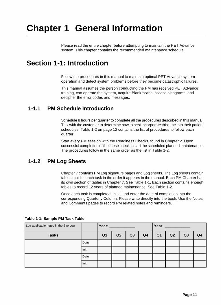
1-1.1 PM Schedule Introduction
Schedule 8 hours per quarter to complete all the procedures described in this manual.Talk with the customer to determine how to best incorporate this time into their patientschedules. Table 1-2 on page 12 contains the list of procedures to follow eachquarter.
Start every PM session with the Readiness Checks, found in Chapter 2. Uponsuccessful completion of the these checks, start the scheduled planned maintenance.The procedures follow in the same order as the list in Table 1-2.
1-1.2 PM Log Sheets
Chapter 7 contains PM Log signature pages and Log sheets. The Log sheets containtables that list each task in the order it appears in the manual. Each PM Chapter hasits own section of tables in Chapter 7. See Table 1-1. Each section contains enoughtables to record 12 years of planned maintenance. See Table 1-2.
Once each task is completed, initial and enter the date of completion into thecorresponding Quarterly Column. Please write directly into the book. Use the Notesand Comments pages to record PM related notes and reminders.
Table 1-1: Sample PM Task Table
Log applicable notes in the Site Log Year: ____________ Year: ____________
Tasks Q1 Q2 Q3 Q4 Q1 Q2 Q3 Q4
Date
Init.
Date
Init
Page 11

PET ADVANCE PLANNED MAINTENANCE MANUAL GE MEDICAL SYSTEMS
DIRECTION 2240409-100, REVISION 2
Section 1-2: PM Schedule
Table 1-2 contains the recommended list of PM Tasks and frequency interval.
Table 1-2: Recommended PM Frequency
Task
Frequency Interval(Fiscal Quarters) Notes
Q1 Q2 Q3 Q4
System Readiness Checks:
Reboot the PET Advance system
View Error Log
Run a 5 minute Blank Scan
Inspect the Sinograms
Run/Review pmtAnalysis
X
X
X
X
X
X
X
X
X
X
X
X
X
X
X
X
X
X
X
X
Run the ReadinessChecks at the startof each PM session
Full System Backup X X 2x each year
Check remaining Raw Data capacity X X X X 4x each year
Check Emergency Stops X X 2x each year
Inspect Gantry Fans X X X X 4x each year
Inspect and Clean Gantry Filters X X X X 4x each year
Check Gantry Lamps and Displays X X X X 4x each year
Clean and Inspect the Transmission Ring Belt X X twice each year
Lubricate the Collimator X once each year
Lubricate the Gripper X X X X 4x each year
Test the Source Load Function X X X X 4x each year
Check and Clean the Table Base X X 2x each year
Check and Clean the Cradle Area X X 2x each year
Check Patient Safety Grounds X X 2x each year
Clean the G1 Electronics Cabinet Filters X X X X 4x each year
Check the G1 and G2 Electronics Cabinet Fans X X X X 4x each year
Check OWS & AWS air flow X X X X 4x each year
Check SCSI Enclosure fans X X X X 4x each year
Laser Cam Filmer X X X X Follow VendorManual Instructions
Color Printer X X X X Follow VendorManual Instructions
Page 12 Section 1-2: PM Schedule

Chapter 2 System Readiness Checks
NOTICE Discuss system performance with the customer when contacted to schedule aPM. If the customer describes errors or artifacts, schedule time for correctivemaintenance before starting the scheduled planned maintenance.
• Did any quadrants fail to converge during the most recent Update Gain?
• Did the Blank Scan sinograms contain any lines or artifacts?
Section 2-1: Introduction
This chapter contains procedures to determine the health of the system prior tostarting the scheduled planned maintenance. Follow the procedures in this chapter atthe beginning of each PM session. Use these procedures to:
• Reboot the system to a known starting point, and monitor its progress.
• Quickly test the normal operation of the hardware and software.
• Check the system calibration.
NOTICE Start the scheduled planned maintenance as soon as the system passes these basicreadiness checks.
Page 13
PET ADVANCE PLANNED MAINTENANCE MANUAL GE MEDICAL SYSTEMS
DIRECTION 2240409-100, REVISION 2
Section 2-2: Reboot the System
Make sure the system successfully reboots and the Error Log remains free of failures andwarnings before proceeding to the first scheduled planned maintenance procedure. Whenscheduling multiple PM sessions every quarter, follow the instructions in this chapterbefore every PM session. If unacceptable failures occur, open a service dispatch, andcorrect the current problem before starting the PM.
Follow the instructions in this section to reboot all PET Advance subsystems whilemonitoring the TIP window and error logs for failures and warnings.
2-2.1 Reboot a PET Advance System with Sun Sparc OWS
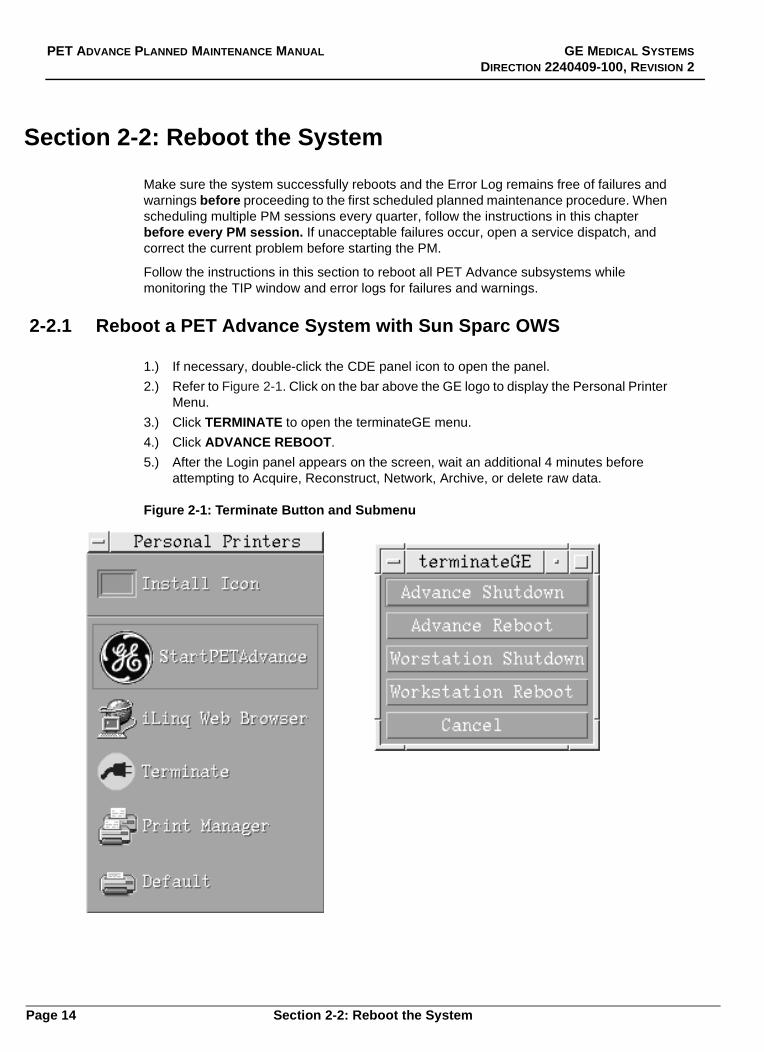
1.) If necessary, double-click the CDE panel icon to open the panel.
2.) Refer to Figure 2-1. Click on the bar above the GE logo to display the Personal PrinterMenu.
3.) Click TERMINATE to open the terminateGE menu.
4.) Click ADVANCE REBOOT.
5.) After the Login panel appears on the screen, wait an additional 4 minutes beforeattempting to Acquire, Reconstruct, Network, Archive, or delete raw data.
Figure 2-1: Terminate Button and Submenu
Page 14 Section 2-2: Reboot the System

GE MEDICAL SYSTEMS PET ADVANCE PLANNED MAINTENANCE MANUAL
DIRECTION 2240409-100, REVISION 2
2-2.2 Reboot a PET Advance System with Hewlett Packard OWS
Note: This procedure also works on the Sun Sparc workstation. Recommended: Use theautomated procedure in Section 2-2.1 to reboot the Sparc, whenever possible.
1.) Logon to the system as root.
• If logged on as operator, log off, then log on as root.
• Type/enter the root password to display the PET Advance system desktop.
2.) Right-click in the screen to display the menu.
3.) Select TOOLS to display its submenu.
4.) Select TERMINAL to open a terminal window. Refer to Figure 2-2.
• Move the cursor into the window to activate it.
5.) Type/enter: terminate -reboot all
6.) After the Login panel appears on the screen, wait an additional 4 minutes beforeattempting to Acquire, Reconstruct, Network, Archive, or delete raw data.
Figure 2-2: Terminal Window
Section 2-2: Reboot the System Page 15

PET ADVANCE PLANNED MAINTENANCE MANUAL GE MEDICAL SYSTEMS
DIRECTION 2240409-100, REVISION 2
Section 2-3: Open Tip Windows
Open the four Tip windows on the desktop and monitor the subsystems while they reboot.
1.) Logon as Service and open the Service Desktop.
2.) Click SERVICE to open its menu.
3.) Click or drag to TERMINAL INTERFACE PKG. to display its submenu.
4.) Click or drag to TIP ALL to open the following subsystem windows:
• Table
• Gantry
• SHARC
• EDCAT
5.) Press <ctrl><X> in each tip window to reboot the corresponding subsystem.
6.) Monitor the contents of each tip window for failures and warnings.
• IF unacceptable failures occur, open a service dispatch, and correct the currentproblem before starting the PM.
Page 16 Section 2-3: Open Tip Windows

GE MEDICAL SYSTEMS PET ADVANCE PLANNED MAINTENANCE MANUAL
DIRECTION 2240409-100, REVISION 2
Section 2-4: View Error Log
2-4.1 Introduction
The Error Log Viewer records hardware and software errors as they occur at thecorresponding OWS or AWS workstation. (The AWS cannot display OWS’s error log, orvice versa.)The Error Log holds one week’s messages. Once every seven days, the Error Logautomatically transfers the messages from the past week to a Unix file. The Unix fileshold the messages from the past five weeks. When the Error Log starts a new week ofmessages, the system deletes the oldest week from the Unix file.
Figure 2-3: Error Log Viewer
Section 2-4: View Error Log Page 17

PET ADVANCE PLANNED MAINTENANCE MANUAL GE MEDICAL SYSTEMS
DIRECTION 2240409-100, REVISION 2
2-4.2 View the Error Log
The Error Log defaults to the Operator Message Level when opened. Remember to enterthe Service or Programmer levels for more detailed messages.
1.) Click on UTILITIES to open its menu.
2.) Select ERROR LOG VIEWER to display the corresponding panel.Refer to Figure 2-3.
• The Error Log lists the messages in the order they occurred, from oldest, to mostrecent message.
• If the log contains multiple pages, the display defaults to the page with the mostrecent messages.
3.) Use the scroll bar to view additional messages.
4.) The system defaults to display all available messages.
5.) Select UPDATE MESSAGES to display:
• The most recently selected Error Log Viewer option(s).
• Any messages that entered the log since being opened.(The display does NOT automatically update.)
6.) Select RESET to restore the default mode, which displays all messages.
7.) To exit the Error Log Viewer, click on OPTIONS to display the following items:
• Set Aside Screen: Select this option to collapse the Error Log Viewer to an Icon.Double-click on the icon to reopen the Error Log Viewer panel.
• Quit Screen: Select this option to exit the Error Log Viewer function.
2-4.3 Acceptable Errors
The Error Log records:
• Pilot errors
• Normal boot up entries
• Normal system messages
• Errors
• Warnings
With the exception of the "Collimator axis did not reach desired position in time" message, if theError Log contains error messages that indicate a system failure, open a service dispatchand troubleshoot the error before proceeding with the scheduled PM.
Page 18 Section 2-4: View Error Log

GE MEDICAL SYSTEMS PET ADVANCE PLANNED MAINTENANCE MANUAL
DIRECTION 2240409-100, REVISION 2
Section 2-5: Acquire a Blank Scan
Run a 5 minute Blank scan and inspect all slices of sinogram for any artifacts.
• IF the system doesn’t pass evaluation, open a new service dispatch totroubleshoot and correct the problem.
2-5.1 Inspect the Sinograms
Use the diagAnalysis/Show Sino tool to verify blank scan uniformity and rule out thepresence of dead modules, blocks or crystals, that appear as dark lines on the sinogram.The system generates a total of 66 sinograms, but only examine the odd numberedsinograms between 1 and 35.
NOTICE If dead blocks appear, open a service dispatch, then use the diagnostics andSingles calibrations to help diagnose and repair the problem. Do NOT process andsave a Blank Scan correction until it is artifact-free.
The following list contains known artifacts that sometimes appear on Blank Scansinograms. If the following artifacts occur, open a service dispatch and run additionaldiagnostics to locate the problem.
• Single black lines: At least one channel in the block has fallen out of the DAC Plotlimits, defined by the ACEM board. The system could also have a conflict betweenEnergy cals and Position Map cals, or an invalid CTC.
• Wide black bands: Multiple blocks are effected by the failure. The system could havea problem with the hardware controlling that group of blocks, or an invalid CTC.
• Single white lines: The corresponding crystal map may not be correct for thatchannel.
• Plaid wallpaper: Invalid CTC (when obvious in all slices)
• Slice 1 or Slice 35 displays a totally different pattern from the remaining slices:Reposition the collimator.
• Vertical bars in the Sinogram: Incorrect Pin Home setting
• Faint lines in the Sinogram: Run PMT Update and CTC.
Section 2-5: Acquire a Blank Scan Page 19

PET ADVANCE PLANNED MAINTENANCE MANUAL GE MEDICAL SYSTEMS
DIRECTION 2240409-100, REVISION 2
2-5.2 Run pmtAnalysis
This section will create files, which will determine if the PMT’s are within the systems gainadjustment window. It will generate a text file, which shows adjustment (the number of turnsof alignment pot) needed to bring PMT’s back within this adjustment window. Refer toFigure 2-4.
1.) From the OWS, open an xterm window, type pmtAnalysis to run the pmtAnalysisprogram.
2.) Press <Enter>. This will create file pmtTune.txt in the /var/tmp directory.
3.) In the xterm window, type mv pmtTune.txt pmtTune1.txt to rename thepmtTune.txt file to pmtTune1.txt.
4.) Press <Enter>.This creates a new pmtTune1.txt file for data comparison later.
5.) Data in the text file pmtTune1.txt will list the detector assemblies (0-55), six detectorblocks per module, two tubes per block, and two cathodes (channels) per tube (dABor dCD). Each channel (A, B, C, or D) will have a DAC value listed. Each tube (dAB ordCD) will list how many turns (+/-) to bring associated tube back within the systemscalibration window. However, an adjustment is only needed when a Warning is listedunder the unit stat or module stat column at the right of file printout. Refer toFigure 2-4.
Important: If an adjustment is necessary, complete the PM and open a separate service call toadjust the affected PMT’s.
Page 20 Section 2-5: Acquire a Blank Scan

GE MEDICAL SYSTEMS PET ADVANCE PLANNED MAINTENANCE MANUAL
DIRECTION 2240409-100, REVISION 2
Figure 2-4: Example of PMTtune.txt FileUnit# A B C D dAB dCD unit stat module stat
0u0 77 87 74 114 1 1
0u1 88 93 86 90 1 1
0u2 109 79 66 58 1 2
0u3 85 82 85 74 1 2
0u4 67 81 76 68 2 2
0u5 60 70 93 85 2 1
- - - - - - - - - - - - - - - - - - - - - - - - - - - - - - - - - - - - - - - - - - - - - - - - - - - - -
1u0 67 81 86 80 2 1
1u1 85 98 94 112 1 0
1u2 97 120 88 105 0 1
1u3 68 89 87 92 2 1
1u4 127 101 111 100 0 0
1u5 99 132 107 85 -1 1
Note DAC Values
- - - - - - - - - - - - - - - - - - - - - - - - - - - - - - - - - - - - - - - - - - - - - - - - - - - - -
31u0 66 53 52 66 3 3
31u1 49 55 71 67 3 2
31u2 63 66 54 55 2 3
31u3 79 66 60 69 2 2
31u4 61 60 56 76 2 2
31u5 86 50 58 80 2 2
- - - - - - - - - - - - - - - - - - - - - - - - - - - - - - - - - - - - - - - - - - - - - - - - - - - - -
55u0 121 88 103 102 0 0
55u1 107 114 124 110 0 -1
55u2 121 143 107 103 -1 0
55u3 112 90 121 120 0 -1
55u4 112 120 118 100 -1 0
55u5 99 114 111 138 0 -1
PMT Module 0
PMT Module 1
PMT Module 31
PMT Module 55
Adjustment Needed"Out of Spec"
warning
warning
Section 2-5: Acquire a Blank Scan Page 21

PET ADVANCE PLANNED MAINTENANCE MANUAL GE MEDICAL SYSTEMS
DIRECTION 2240409-100, REVISION 2
Notes and Comments:
Page 22 Section 2-5: Acquire a Blank Scan

Chapter 3 System/ServiceAdministration Tasks
This chapter contains the procedures used to backup the system and check theSHARC Raw Data disk capacity.
Section 3-1: Full System Backup
Follow the instructions in this section to backup the PET Advance software on theinternal AWS or OWS disk. Label each backup tape with the software release,Hostname and date.
NOTICE Power down and/or disconnect all external disk drives to prevent the backup softwarefrom attempting to backup all the files on these external drives.
NOTICE Keep at least one current backup tape per workstation, to facilitate recovery after acatastrophic failure or the loss of the system disk. Backup each workstation after asite load and after any software update.
3-1.1 Backup the System Files
1.) Logon to the system as root.
• If logged on as operator, log off, and then log on as root.
• Type/enter the root password.
2.) Insert a write enabled DAT into the tape drive.
3.) Right-click in the screen to display the menu.
4.) Select TOOLS to display its submenu.
5.) Select TERMINAL to open a terminal window.
a.) Move the cursor into the window to activate it.
b.) Type/enter the following:
/usr/PET/install/PET_backup [ENTER]
6.) The window displays a screen of backup options.
7.) Type F and/or press ENTER to select the default Full Backup function.
• The screen continues to update and display the backup progress.
NOTICE It could take 45 minutes to an hour to backup the system. Proceed to othertasks, such as checking the fans during this time.
Page 23

PET ADVANCE PLANNED MAINTENANCE MANUAL GE MEDICAL SYSTEMS
DIRECTION 2240409-100, REVISION 2
NOTICE During the backup process, the screen displays status information. The system triesto backup the configuration file of every available option. If the system doesn’t havean option, the screen will display the notification that it cannot backup thecorresponding configuration file. This is not an error.
8.) When the backup completes, the command prompt appears.
• Optional: To view the backup file index, one page at a time, type:
more /tmp/index [ENTER]
• Type Q (Quit) to exit the backup file index.
9.) Remove the 3MB backup file index from the disk by typing:
rm /tmp/index [ENTER]
10.) The system responds with:
rm : remove /tmp/index:? (y/n)
11.) Initiate the removal process by typing:
y [ENTER]
12.) Click the CDE Panel EXIT button to Log out.
13.) Eject the DAT from the drive.
14.) Label the DAT with today’s date, Hostname and software release number.
NOTICE Use the PET Application software ARCHIVE function to backup the Blank Scan, 2D/3D Normalization and Well Counter corrections on a separate DAT.
Page 24 Section 3-1: Full System Backup

GE MEDICAL SYSTEMS PET ADVANCE PLANNED MAINTENANCE MANUAL
DIRECTION 2240409-100, REVISION 2
Section 3-2: Check the Raw Data Disk Capacity
Follow the procedure in this section to check the available disk space on the raw datadisk in the PET Advance SHARC. IF customers consistently operate the system with thedatabase more than 80% full, they will run out of disk space and generate system errors.The PM session provides an opportunity to check the database levels, and teach thecustomers to regularly archive the patient data and delete it from the disk.
3-2.1 Calculate the Frame Capacity
Note: Use the OWS to access raw data disk space information. This information cannot beaccessed from the AWS.
1.) Click on UTILITIES to open its menu.
2.) Select RAW DISK DEFRAGMENTATION to display the corresponding panel.
3.) Select the FRAME CALCULATOR button to display the Frame Calculator panel.
4.) Select Scan Type: PATIENT ACQUISITION
5.) Select Axial Acceptance Angle: 2D
6.) Select Mode: WORD
7.) Select Randoms area: PROMPTS + DELAYS
8.) The Frame Calculator uses user inputs to determine the Current Frame Capacityand the Additional Frame Capacity after Full Defragmentation.
• IF the Current Frame Capacity falls below 120 frames, notify the customer thatthe disk is almost full. Urge them to establish a schedule to periodically archivethe patient image and raw data files, and remove the old files from thecorresponding disks. If they already have a process in place, urge them to archivethe files and delete the data more frequently, to keep the raw data disk capacityas far above 120 frames as possible.
9.) Optional: If the Current Frame Capacity exceeds 120 frames, proceed to section 3-2.2 and defragment the disk.
• IF the Current Frame Capacity falls below 120 frames, defragmentation will notsignificantly increase the capacity. Ask the customer to archive and delete the olddata first, then defragment the disk.
10.) Select CANCEL to close the Frame Calculator panel.
Section 3-2: Check the Raw Data Disk Capacity Page 25

PET ADVANCE PLANNED MAINTENANCE MANUAL GE MEDICAL SYSTEMS
DIRECTION 2240409-100, REVISION 2
3-2.2 Defragment the Raw Data Disk
This procedure rearranges the existing information on the raw data disk to create largercontiguous file spaces, which in turn increases the potential frame capacity.
NOTICE This procedure is applicable to older SHARC (MV147) systems only. This proceduredoes not apply to the newer SHARC (MV2400) systems which perform automaticdefragmentation. To determine system configuration, look at the applicable label onthe SBC within the cabinet.
NOTICE When selecting this function, the software denies raw data disk access to the rest ofthe system. Remember to CANCEL this function when finished.
1.) Click UTILITIES to open its menu.
2.) Select RAW DISK DEFRAGMENTATION to display the corresponding panel.
3.) Select the START button to initiate the defragmentation process.
• Select STOP at any time during the defragmentation operation. The systemcompletes the current file, then stops the defragmentation operation, and returnsto the Idle Status state.
• The START selection disables the CANCEL selection; select STOP to reactivatethe CANCEL function.
4.) A panel indicator displays system progress and one of the following status indicators:
• Idle: System ready and waiting; select START to defragment the disk, orCANCEL to close the panel.
• Initiating: Select START. The system prepares to defragment the disk.
• In Progress: The system started to defragment the disk.
* The Percent Complete slider shows the current progress, by percentage.
* The Files Moved field displays the number of files actually moved.
* The Total Free Space field displays the free raw data disk space in Mbytes.
• Canceled: STOP was selected before the system finished defragmentation.
• Complete: The system successfully finished the disk defragmentation process.
5.) Select CANCEL to exit the Disk Defragmentation panel, and return raw data accessto the rest of the system.
Page 26 Section 3-2: Check the Raw Data Disk Capacity

GE MEDICAL SYSTEMS PET ADVANCE PLANNED MAINTENANCE MANUAL
DIRECTION 2240409-100, REVISION 2
Section 3-3: Check the Emergency Buttons
The PET Advance system has two types of Emergency buttons:
• Emergency Stop: The Emergency Stop buttons halt all table and gantry motion,and turn off the laser alignment lights.
• Emergency OFF: The Emergency OFF button removes power from all systemcomponents. Do NOT check the Emergency OFF function during this PM, becauseit could cause system failures.
CAUTION Pressing the Emergency Stop or Emergency OFF buttons during a scan, will cause thesystem to abort the data acquisition.
3-3.1 Emergency Stop Buttons
The Emergency Stop buttons stop scanner operations, while leaving the OWS alone.Press an Emergency Stop Button to halt all table and gantry functions, release the cradlelatch, and send the transmission source(s) back to the shield. The system aborts anydata acquisition in progress, and attempts to save all data acquired prior to the abort.
RADIATION IF A PIN SOURCE IS OUT OF THE SHIELD WHEN ANY EMERGENCY STOP ISPRESSED, THE PIN REMAINS OUTSIDE THE SHIELD. MAKE SURE THE PINSOURCE IS IN THE SHIELD WHEN PRESSING EACH EMERGENCY STOP BUTTON.
The PET Advance system has four Emergency Stop Buttons:
1.) Refer to Figure 3-1. Each control panel on the front of the gantry has an EmergencyStop button, for a total of two. The rear cover of the gantry has one Emergency Stopbutton. Locate the Emergency Stop Buttons.
2.) Press and reset each of the three gantry emergency stop buttons.
• Refer to Figure 3-1. Twist the Emergency Stop button in the direction of thearrows to release and reset it.
3.) Refer to Figure 3-2. The OWS hardkey control panel has one Emergency Stopbutton.
4.) Press and reset the Emergency Stop button on the OWS hardkey control panel.
Section 3-3: Check the Emergency Buttons Page 27

PET ADVANCE PLANNED MAINTENANCE MANUAL GE MEDICAL SYSTEMS
DIRECTION 2240409-100, REVISION 2
Figure 3-1: Gantry Control Panel
Figure 3-2: Hard Key Control Panel (Emergency Stop)
Emergency Stop button
Emergency Stop button
Page 28 Section 3-3: Check the Emergency Buttons
Chapter 4 Gantry and Table
Follow the procedures in this chapter to check the Gantry fans, filters, lamps, displays,and basic mechanical operations. For best results, stand on a step stool or ladder tocheck the fans.
Section 4-1: Gantry Fans, Filters and Lamps
Inspect the following five gantry fans for normal operation:
• 2 REDDOG card rack fans
• 2 REDDOG power supply fans
• Top cover fan
WARNING TAKE CARE TO MAINTAIN A SAFE WORKING DISTANCE FROM THEOPERATING FANS. TO PREVENT INJURY, REMOVE OR SECURELOOSE CLOTHING OR JEWELRY BEFORE APPROACHING THE FANS.
4-1.1 Inspect the Gantry Fans
1.) Remove the gantry side covers and open the gantry rear covers.
2.) Locate the REDDOG fans at the top of each card rack.
3.) Check that the REDDOG fans turn at approximately the same speed.
4.) Locate the fans on the REDDOG power supplies.
• The power supplies are located at the top rear of the gantry mounting plate.
• The power supply fans are located on the rear of each power supply, and faceeach other.
5.) Hold the edge of a single sheet of paper, and move it toward the grill of either fan.
• The paper should pull against the grill.
• The new Astec Power Supply fans blow air outwards away from the fan grill.
6.) Move the paper toward the second fan grill.
• The paper should pull against the grill.
• The new Astec Power Supply fans blow air outwards away from the fan grill.
7.) Locate the fan attached to the top cover of the gantry.
8.) Check for normal top cover fan operation.
Page 29

PET ADVANCE PLANNED MAINTENANCE MANUAL GE MEDICAL SYSTEMS
DIRECTION 2240409-100, REVISION 2
4-1.2 Inspect and Clean the Gantry Filters
Note: Power does not need to be removed from the REDDOG card racks to clean the filters.
1.) Locate the REDDOG air intake filters, at the base of each card rack.
2.) Grasp the front edge of the filter, and pull it straight out of its bracket.
• If the filter offers any resistance, check the bottom of the bracket for screws.
• If present, loosen the screws that fasten the filter to the bracket.
3.) Vacuum BOTH sides of the filter to remove surface dust and debris.
4.) If necessary, run a stream of hot water over the filters, to flush out any debris.
NOTICE Let the filters dry COMPLETELY before sliding them back into place.
5.) Orient each filter so its air indicator points up, and slide it back into its bracket.
6.) Close the rear gantry covers.
7.) Replace the side covers.
4-1.3 Check the Gantry Lamps and Displays
Before starting, ask the operator if he or she noticed any burned out lamps or displays.
Note: If a burned out lamp is found, open a service dispatch and replace the lamp, NOT the board.Lamp part number: 46-278641P1Electronic Grade RTV: 46-170137P1
Initiate the Gantry Display Test from the Service Menu:
1.) Click SERVICE to display its menu.
2.) Click DIAGNOTICS to display its submenu.
3.) Click or drag to GANTRY to display its submenu.
4.) Click or drag to FRU to access the display tests.
• The Display FRU test places the 3 gantry displays into a diagnostic mode, similarto the sequence it undergoes during power up.
5.) Make sure all display components illuminate; the system doesn’t display any status.
• For best results replace the entire group of four lamps whenever a single lamp inthat group burns out.
• If necessary, refer to the service documentation for instructions to remove thepanels, replace and RTV the burned out lamps or displays.
6.) Optional: Reboot the gantry to check for burned out lamps or displays.
Page 30 Section 4-1: Gantry Fans, Filters and Lamps

GE MEDICAL SYSTEMS PET ADVANCE PLANNED MAINTENANCE MANUAL
DIRECTION 2240409-100, REVISION 2
Section 4-2: Gantry MechanicsFollow the procedures in this section to check the reliability, range of movement andnormal operation of the listed components. Do not attempt to recharacterize the gantrymechanics at this time.
• Transmission Ring Belt (twice each year)
• Collimator (once each year)
• Source Loader and gripper (four times each year)
• Patient Table (four times each year)
4-2.1 Clean and Inspect the Transmission Ring BeltEvery six months:
• Clean the belt drive pulley, belt ring and belt drive with Isopropyl alcohol, tomaintain optimal source drive operation.
• Check the belt for proper tension and inspect it for cracks.
DANGER TO PREVENT INJURY, REMOVE POWER TO THE GANTRY,LOCKOUT AND TAG THE SYSTEM BEFORE PROCEEDING ANYFURTHER.
If necessary, refer to the Gantry power down and general access procedures in theAdvance System Service manual. (Direction 2100507)
1.) Turn off gantry power from the Electronics Cabinet.
2.) Tag and lock out the system.
3.) Remove both side covers and the service access panel.
4.) Open both rear covers.
5.) Measure and record the length of the spring on the T-Ring Drive module. The springshould measure 25mm on both G1 and G2 gantrys.
6.) Remove the spring tensioning knob from the shaft.
7.) Remove screws that fasten the motor plate to the module housing to release thedrive belt tension.
8.) Remove four screws that fasten the pulley retainer plate to the module housing.
9.) Remove the plate and two pulleys.
10.) Remove the belt from the drive ring and check it for cracks.
• If cracks or excessive wear occurs, open a service dispatch and replace the drivebelt.
11.) Thoroughly clean the drive ring, drive belt pulley and internal belt drive assemblysurfaces with isopropyl alcohol.
12.) Wait until all surfaces dry, then slide the drive belt over the drive ring, and reattachthe pulleys and retainer plate to the drive module.
13.) Reattach the spring to the T-Ring Drive module.
14.) Measure the spring, and make sure its length matches the Step 5 value.
• Do not tighten the motor plate screws until the spring is set.
15.) Manually rotate the ring several times to check belt alignment. The belt should notbind, catch or rub against the outer edge of the drive bearing.
16.) Restore power to the gantry.
17.) Run two or more source load cycles to verify system operation.
18.) Reassemble the gantry covers and restore the system to normal operation.
Section 4-2: Gantry Mechanics Page 31
PET ADVANCE PLANNED MAINTENANCE MANUAL GE MEDICAL SYSTEMS
DIRECTION 2240409-100, REVISION 2
4-2.2 Lubricate the Collimator
Lubricate the collimator once a year, and any time the Error Log contains the followingmessage:
The collimator axis did not reach desired position in time.
NOTICE Do NOT apply oil to the Collimator rails. Oil on the collimator rails will generatecollimator errors.
Once a year, lubricate the collimator bearings with Mobiletemp SHC Grease orequivalent, GE part number 46-256047P1. The wrong type of grease will generatecollimator errors.
1.) Check the Error Log for collimator related error messages.
2.) The Collimator has grease fittings on each of the four bearings. If necessary, refer tothe service documentation for illustrations and additional information.
3.) Apply bearing grease from a grease gun into each of the four fittings.
NOTICE Do NOT over grease the bearings! Apply a single "pump" of grease to each fitting.Too much grease in the fittings will generate collimator errors.
Page 32 Section 4-2: Gantry Mechanics

GE MEDICAL SYSTEMS PET ADVANCE PLANNED MAINTENANCE MANUAL
DIRECTION 2240409-100, REVISION 2
4-2.3 Lubricate the Source Loader Gripper
Follow the procedure in this section to lubricate the gripper. Use silicon spray (partnumber 46-170230P1), metric Allen wrenches and a soft towel or tissues.
CAUTION Remove gantry power to prevent unintended loader movement or damage. Tagand Lock out system power.
1.) Remove gantry PCU power to disable the source loader arm.
2.) Refer to Figure 4-1 on page 34. Remove the service access panel from the rear ofthe gantry to expose the loader arm.
3.) Pull the rotational drive assembly backward to the rear of the gantry and rotate thearm assembly upward, to access the gripper located on the end of the arm. The armshould also be clear of the collimator and source ring.
4.) Remove four screws that fasten the gripper stop plate to the gripper housing.
5.) Remove stop plate and pin bushing from the gripper assembly.
• Carefully remove the three springs from the housing.
6.) Remove the two screws that fasten the cover to the gripper housing.
7.) Remove cover, gripper slide block, and the slide block spring.
8.) Remove slide block spring from the slide block.
9.) Use a soft towel or tissues to remove all dirt and oil from the slide block and all theinterior and exterior surfaces of the bushing.
10.) Use a soft towel or tissue to remove all dirt and oil from the slot on the housing wherethe slide block slides, and the hole in which the bushing is inserted.
11.) Spray a thin coat of silicon spray on all surfaces of the slide block and bushing.
• Spray the interior and exterior diameter surfaces of the bushing.
Section 4-2: Gantry Mechanics Page 33

PET ADVANCE PLANNED MAINTENANCE MANUAL GE MEDICAL SYSTEMS
DIRECTION 2240409-100, REVISION 2
Figure 4-1: Pin Gripper Assembly (46-325063)
Page 34 Section 4-2: Gantry Mechanics

GE MEDICAL SYSTEMS PET ADVANCE PLANNED MAINTENANCE MANUAL
DIRECTION 2240409-100, REVISION 2
4-2.4 Test the Source Loader Function
Do NOT run Characterizations on the Source Loader during the PM.
CAUTION To prevent damage to the system mechanics, take care not to move the SLR or SLTinto a mechanical interference position with the transmission ring, cabling, sourceholder or collimator during this test.
This section describes the reassembling of the gripper, and checks for normal operation.Avoid touching the lubricated surfaces.
NOTICE When replacing the gripper housing cover, take care to align the cover with thehousing, and hold it firmly while fastening it into place.
1.) Assemble the gripper, then push in the bushing and let it spring back several times.
2.) Push in the solenoid rod and let it spring back several times to slide the block backand forth and test the gripper housing cover alignment.
• The solenoid rod should travel freely. It should not bind or catch on the cover.
3.) Remove the Power Lockout lock and tag.
4.) Restore power to the gantry.
5.) Use the gantry Hand Held Service Control Panel to run 5 load/unload sequences, toverify normal operation.
Section 4-2: Gantry Mechanics Page 35

PET ADVANCE PLANNED MAINTENANCE MANUAL GE MEDICAL SYSTEMS
DIRECTION 2240409-100, REVISION 2
Section 4-3: Basic Table Checks
4-3.1 Check and Clean the Table Base Assemblies
Follow the procedure in this section to check the single cooling fan for the Table electronics,and the table to baseplate connections. This section also contains cleaning instructions.
1.) Remove both bottom covers from the patient table assembly.
2.) Locate the fan next to the power switch and service outlet box.
• Verify normal fan operation.
3.) Check or tighten the 4 (corner) bolts that fasten the table to the baseplates.
• These bolts may loosen with long term activity.
NOTICE Remove power from the table, then lockout and tag the system before tightening thethe baseplate bolts and vacuuming the table interior.
4.) Vacuum interior to remove any visible dust and debris from the bottom of the table.
5.) If necessary, use a can of compressed air to blow dust from the table circuit boardsand power supplies.
6.) Restore table power.
7.) Fasten two bottom covers back into place.
Page 36 Section 4-3: Basic Table Checks

GE MEDICAL SYSTEMS PET ADVANCE PLANNED MAINTENANCE MANUAL
DIRECTION 2240409-100, REVISION 2
4-3.2 Check and Clean the Cradle Area of the Table
Follow the procedure in this section to clean and inspect the cradle area of the table.
1.) Remove all accessories from the table top.
2.) Drive the cradle in and out of the gantry, and watch for smooth travel, with nocatching or binding.
• If the cradle jerks during travel, check the bottom of the cradle for adhesiveresidue when removed from the table.
3.) Latch the cradle carriage into the Home position.
WARNING IF SHARPS (NEEDLES, SYRINGES, SCALPELS) OCCUR OR PATIENTFLUIDS ARE IN THE CRADLE AREA, IMMEDIATELY CONTACT THEDEPARTMENT SUPERVISOR FOR SAFE DISPOSAL AND CLEANUP.
4.) Remove six plastic covers and six bolts that fasten cradle bed to the cradle carriageassembly.
5.) Inspect cradle carriage and table top interior for sharps or fluids.
6.) Vacuum any dust or debris from the table top interior, and clean the bottom plate.
CAUTION To prevent damage to the encoder, ALWAYS grasp and hold the cradle carriagewhen unlatching the cradle drive.
7.) Unlatch the cradle drive and move the cradle carriage along the length of the table.
• The carriage should move smoothly and freely along the carriage rails.
• When resistance or uneven travel occurs, clean the carriage rails.
8.) Latch cradle carriage into the Home position.
9.) Fasten cradle bed to the carriage with six bolts.
10.) Replace the plastic bolt covers.
11.) Wipe off cradle and table surfaces.
12.) Replace table pads and accessories.
13.) Raise and lower the table, and check for smooth operation.
• IF table catches or binds, and fails to move smoothly, open a service dispatch totroubleshoot the problem.
Section 4-3: Basic Table Checks Page 37
PET ADVANCE PLANNED MAINTENANCE MANUAL GE MEDICAL SYSTEMS
DIRECTION 2240409-100, REVISION 2
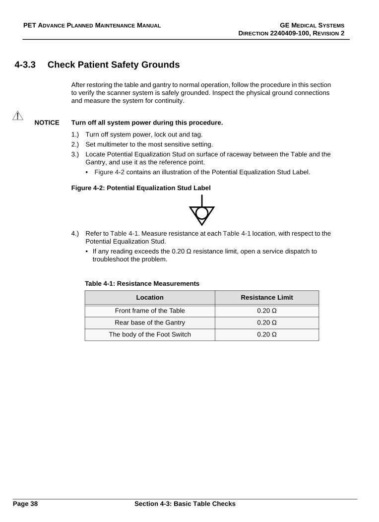
4-3.3 Check Patient Safety Grounds
After restoring the table and gantry to normal operation, follow the procedure in this sectionto verify the scanner system is safely grounded. Inspect the physical ground connectionsand measure the system for continuity.
NOTICE Turn off all system power during this procedure.
1.) Turn off system power, lock out and tag.
2.) Set multimeter to the most sensitive setting.
3.) Locate Potential Equalization Stud on surface of raceway between the Table and theGantry, and use it as the reference point.
• Figure 4-2 contains an illustration of the Potential Equalization Stud Label.
Figure 4-2: Potential Equalization Stud Label
4.) Refer to Table 4-1. Measure resistance at each Table 4-1 location, with respect to thePotential Equalization Stud.
• If any reading exceeds the 0.20 Ω resistance limit, open a service dispatch totroubleshoot the problem.
Table 4-1: Resistance Measurements
Location Resistance Limit
Front frame of the Table 0.20 Ω
Rear base of the Gantry 0.20 Ω
The body of the Foot Switch 0.20 Ω
Page 38 Section 4-3: Basic Table Checks

Chapter 5 Electronics Cabinet
The PET Advance system has two versions of the Electronics Cabinet that houses theSHARC and EDCAT subsystems.
IF the PET Advance has a G1 Cabinet:
• Follow the instructions in Section 5-1 to clean the cabinet filters.
• Follow the instructions in Section 5-2 to inspect the fans.
IF the PET Advance has a G2 Cabinet:
• Follow the instructions in Section 5-2 to inspect the fans.
Section 5-1: Clean the Electronics Cabinet Filters
The G1 Electronics Cabinet has two aluminum mesh filters, one accessed from thefront of the cabinet, and one accessed from the rear of the cabinet.
CAUTION Remove power from the Electronics Cabinet and tag and lock the system.
1.) Open the lockout door on the rear of the PDU.
2.) Shut OFF the circuit breakers labeled, ELECTRONICS CABINET, andSERVICE OUTLETS.
• The green LED should extinguish when the CB is turned off.
3.) Open the front Electronics Cabinet door:
a.) Remove fiber optic connector, J7, from the GASM board.
b.) Remove 120mm high blank panel, located beneath card rack, and guidefiber optic cable through the bushing in the panel.
c.) Locate the filter, now visible, beneath the rack.
d.) Grip the front and rear edge of the filter and pull it straight out.
•The filter is 416mm long, and may bend if pulled by the front edge.
4.) Open the rear cabinet door by loosening the locking screws located at the topand bottom of the door.
5.) Locate rear filter, beneath bottom of the card rack connector panel.
6.) Check cables and move any that may interfere with the filter removal.
7.) Grip front and rear edges of the 144mm long filter, and pull it straight out of thecabinet. Take care not to bend the filter edges when removed.
8.) Clean filters with soap and warm water, and shake off the excess water.
9.) Let the filters dry completely, then spray the side clips with a light oil to preventrusting, before sliding them back into place.
NOTICE To prevent damage to the system circuit boards, make sure the filters arecompletely dry before sliding them back into the cabinet. Prop the filtersupright to dry, and turn them periodically so any water that collected inside theedges has a chance to run out.
Page 39

PET ADVANCE PLANNED MAINTENANCE MANUAL GE MEDICAL SYSTEMS
DIRECTION 2240409-100, REVISION 2
10.) Slide large filter beneath card rack in the front of the cabinet.
11.) Slide small filter into place in the rear of the cabinet.
12.) Guide fiber optic cable back through bushing in the blank panel.
13.) Insert blank panel beneath card rack in front of the cabinet.
14.) Plug J7 back into the GASM board.
15.) Inspect and vacuum the intake grills.
16.) Proceed to the next section -or- Close and fasten the rear cabinet door.
Section 5-2: Check the Electronics Cabinet Fans
Each G1 and G2 Electronics Cabinet has four fans, two on the front panel of the PDU, oneon the card rack power supply and the main exhaust fan attached to top of the cabinet.
5-2.1 Inspect the Card Rack and PDU Fans
All fans should appear to run smoothly and quietly, at the same speed.
• Open a Service Dispatch to replace any problem fans.
• The System Service Manual has fan replacement procedures.
5-2.2 Inspect the Main Exhaust Fan
Use a step stool or ladder to reach the top of the cabinet and inspect the fan.
1.) Without removing the grill, check that the fan exhausts air.
• The fan should appear to run smoothly.
2.) If necessary, remove any dust or debris from the top of the cabinet and grill.
3.) Listen for any abnormal vibration of the fan blades.
• During normal operation, the fan vibrates a little bit. When one of the balanceweights falls off the blade, the fan vibrates noticeably.
• If the fan vibrates excessively, open a service dispatch to replace it. The systemservice documentation contains fan replacement procedures.
Page 40 Section 5-2: Check the Electronics Cabinet Fans

Chapter 6 Peripheral Devices
This chapter contains planned maintenance procedures for the following PETAdvance system peripheral devices:
• OWS (Sun or HP)
• AWS (option - Sun or HP)
• 4mm Tape Drive with SCSI enclosure
• Laser Camera Filmer (option - 3M, Kodak)
• Color Printer (option - Kodak, Codonics)
This chapter contains non-invasive functional tests of the peripherals. Some sitesmay have local contracts with vendors to maintain some peripherals. For mostefficient use of scanner downtime, schedule concurrent vendor PMs.
Section 6-1: OWS and AWS
Follow the procedure in this section to check the air flow to the PET OWS and anyoptional AWS workstations.
1.) Inspect the front grill of the computer and vacuum any visible dust or debris.
2.) Hold a tissue near the front grill.
• The fan should produce enough suction to pull the tissue against the grill.
3.) Hold a tissue at the back of the computer unit to check the exhaust.
• If necessary, reposition the unit or cables to increase air flow through the unit.
4.) If the fan is dead or going bad, open a service dispatch.
5.) Vacuum behind the workstation components; check all cable connections.
Section 6-2: SCSI Enclosure Fans
Check two fans on the rear of the enclosure assembly for normal operation.
1.) Use a large scrap of paper to check the air flow to both fans.
• Both fans are mounted on the rear of the tower.
• The upper fan is stronger than the lower fan.
2.) Inspect the front grill of the tower and vacuum away any visible dust or debris.
3.) Vacuum behind the DAT tower; check all cable connections.
Section 6-3: Lasercam Filmer
General maintenance is required to achieve a consistent high quality print from thelaser camera. For best results, follow the manufacturer’s instructions to clean the filmpath quarterly, or at least twice each year.
Page 41

PET ADVANCE PLANNED MAINTENANCE MANUAL GE MEDICAL SYSTEMS
DIRECTION 2240409-100, REVISION 2
Section 6-4: Color Printer (Codonics or Kodak)
General maintenance is required to achieve a consistent high quality print from the colorprinter. For best results, clean the print head and path whenever loading a new ribboncartridge. This may be required every quarter and biannually.
Replacement ribbon cartridges are the responsibility of the customer. If replacing this partas part of the PM, check with the customer to ensure a replacement cartridge is availablefor the scheduled PM.
The procedure for replacing the ribbon cartridge is documented in the Maintenance andAdjustments section of the User’s manual provided with the printer.
Page 42 Section 6-4: Color Printer (Codonics or Kodak)

Chapter 7 PM Log Sheets
Section 7-1: Introduction
This chapter contains enough quarterly PM Log sheets and signature pages to last 12years. Use these pages to track progress through each PM list.
• The PM Log sheets should compliment the Site Log, not replace it. For best results,do not mark up these pages with notes that should go into the site log. Use theNotes and Comments pages in this chapter to record PM related reminders andconcerns. If multiple people share site responsibility, use the Notes and Commentspages to keep each other up to date on PM progress and results.
• Advance PM Log Sheet Signature page: Sign and date the correspondingquarter upon completion of all the assigned PM for that quarter. When planing toschedule multiple PM sessions (recommended) initial and enter the date of eachinterim PM session in the space beneath the corresponding signature line. Signname when the last PM of the quarter is completed.
• Synchronize the PM schedule to the GE calendar. For example "Q1" representsPMs in January, February and March, and not the first three months of system useafter installation. When using this manual after fiscal quarter 1 (Q1), start with theschedule and log sheet columns that match the current GE fiscal calendar.
Page 43

PET ADVANCE PLANNED MAINTENANCE MANUAL GE MEDICAL SYSTEMS
DIRECTION 2240409-100, REVISION 2
Section 7-2: Advance PM Log Sheet Signature Page
Sign and date the corresponding quarter when ALL the PM procedures scheduled for thatquarter are completed. When scheduling multiple PM sessions throughout the quarter,initial and enter the date of each interim session beneath the corresponding quarterlysignature line.
Note: Start with the current fiscal quarter, to synchronize the PM schedule to the GE calendar,even if it means leaving blank quarters in the first years signature box.
Table 7-1: Signature Page
Year ____________ Year __________
Q1Signature _________________________ Date _____
Q2Signature _________________________ Date _____
Q3Signature _________________________ Date _____
Q4Signature _________________________ Date _____
Q1Signature _________________________ Date _____
Signature _________________________ Date _____
Q3Signature _________________________ Date _____
Q4Signature _________________________ Date _____
Year ____________ Year ____________
Q1Signature _________________________ Date _____
Q2Signature _________________________ Date _____
Q3Signature _________________________ Date _____
Q4Signature _________________________ Date _____
Q1Signature _________________________ Date _____
Q2Signature _________________________ Date _____
Q3Signature _________________________ Date _____
Q4Signature _________________________ Date _____
Page 44 Section 7-2: Advance PM Log Sheet Signature Page

GE MEDICAL SYSTEMS PET ADVANCE PLANNED MAINTENANCE MANUAL
DIRECTION 2240409-100, REVISION 2
T
able 7-2: Signature PageYear ____________ Year __________
Q1Signature _________________________ Date _____
Q2Signature _________________________ Date _____
Q3Signature _________________________ Date _____
Q4Signature _________________________ Date _____
Q1Signature _________________________ Date _____
Signature _________________________ Date _____
Q3Signature _________________________ Date _____
Q4Signature _________________________ Date _____
Year ____________ Year ____________
Q1Signature _________________________ Date _____
Q2Signature _________________________ Date _____
Q3Signature _________________________ Date _____
Q4Signature _________________________ Date _____
Q1Signature _________________________ Date _____
Q2Signature _________________________ Date _____
Q3Signature _________________________ Date _____
Q4Signature _________________________ Date _____
Section 7-2: Advance PM Log Sheet Signature Page Page 45

PET ADVANCE PLANNED MAINTENANCE MANUAL GE MEDICAL SYSTEMS
DIRECTION 2240409-100, REVISION 2
Table 7-3: Signature Page
Year ____________ Year __________
Q1Signature _________________________ Date _____
Q2Signature _________________________ Date _____
Q3Signature _________________________ Date _____
Q4Signature _________________________ Date _____
Q1Signature _________________________ Date _____
Signature _________________________ Date _____
Q3Signature _________________________ Date _____
Q4Signature _________________________ Date _____
Year ____________ Year ____________
Q1Signature _________________________ Date _____
Q2Signature _________________________ Date _____
Q3Signature _________________________ Date _____
Q4Signature _________________________ Date _____
Q1Signature _________________________ Date _____
Q2Signature _________________________ Date _____
Q3Signature _________________________ Date _____
Q4Signature _________________________ Date _____
Page 46 Section 7-2: Advance PM Log Sheet Signature Page

GE MEDICAL SYSTEMS PET ADVANCE PLANNED MAINTENANCE MANUAL
DIRECTION 2240409-100, REVISION 2
T
Section 7-3: System Readiness Checks
Advanced PM Log Sheets System ID ______________________
Table 7-4: System Readiness Checks
Log applicable notes in the Site Log Year: ____________ Year: ____________
Tasks Q1 Q2 Q3 Q4 Q1 Q2 Q3 Q4
Reboot the PET Advance system Date
Init
View Error Log Date
Init
5 Minute Blank Scan Date
Init
Inspect the Sinograms Date
Init
Run/Review pmtAnalysis Date
Init
able 7-5: System Readiness Checks
Log applicable notes in the Site Log Year: ____________ Year: ____________
Tasks Q1 Q2 Q3 Q4 Q1 Q2 Q3 Q4
Reboot the PET Advance system Date
Init
View Error Log Date
Init
5 Minute Blank Scan Date
Init
Inspect the Sinograms Date
Init
Run/Review pmtAnalysis Date
Init
Section 7-3: System Readiness Checks Page 47
PET ADVANCE PLANNED MAINTENANCE MANUAL GE MEDICAL SYSTEMS
DIRECTION 2240409-100, REVISION 2
System Readiness Notes and Comments:
Page 48 Section 7-3: System Readiness Checks

GE MEDICAL SYSTEMS PET ADVANCE PLANNED MAINTENANCE MANUAL
DIRECTION 2240409-100, REVISION 2
Table 7-6: System Readiness Checks
Log applicable notes in the Site Log Year: ____________ Year: ____________
Tasks Q1 Q2 Q3 Q4 Q1 Q2 Q3 Q4
Reboot the PET Advance system Date
Init
View Error Log Date
Init
5 Minute Blank Scan Date
Init
Inspect the Sinograms Date
Init
Run/Review pmtAnalysis Date
Init
Table 7-7: System Readiness Checks
Log applicable notes in the Site Log Year: ____________ Year: ____________
Tasks Q1 Q2 Q3 Q4 Q1 Q2 Q3 Q4
Reboot the PET Advance system Date
Init
View Error Log Date
Init
5 Minute Blank Scan Date
Init
Inspect the Sinograms Date
Init
Run/Review pmtAnalysis Date
Init
Section 7-3: System Readiness Checks Page 49

PET ADVANCE PLANNED MAINTENANCE MANUAL GE MEDICAL SYSTEMS
DIRECTION 2240409-100, REVISION 2
System Readiness Notes and Comments:
Page 50 Section 7-3: System Readiness Checks

GE MEDICAL SYSTEMS PET ADVANCE PLANNED MAINTENANCE MANUAL
DIRECTION 2240409-100, REVISION 2
T
T
able 7-8: System Readiness Checks
Log applicable notes in the Site Log Year: ____________ Year: ____________
Tasks Q1 Q2 Q3 Q4 Q1 Q2 Q3 Q4
Reboot the PET Advance system Date
Init
View Error Log Date
Init
5 Minute Blank Scan Date
Init
Inspect the Sinograms Date
Init
Run/Review pmtAnalysis Date
Init
able 7-9: System Readiness Checks
Log applicable notes in the Site Log Year: ____________ Year: ____________
Tasks Q1 Q2 Q3 Q4 Q1 Q2 Q3 Q4
Reboot the PET Advance system Date
Init
View Error Log Date
Init
5 Minute Blank Scan Date
Init
Inspect the Sinograms Date
Init
Run/Review pmtAnalysis Date
Init
Section 7-3: System Readiness Checks Page 51

PET ADVANCE PLANNED MAINTENANCE MANUAL GE MEDICAL SYSTEMS
DIRECTION 2240409-100, REVISION 2
System Readiness Notes and Comments:
Page 52 Section 7-3: System Readiness Checks
GE MEDICAL SYSTEMS PET ADVANCE PLANNED MAINTENANCE MANUAL
DIRECTION 2240409-100, REVISION 2
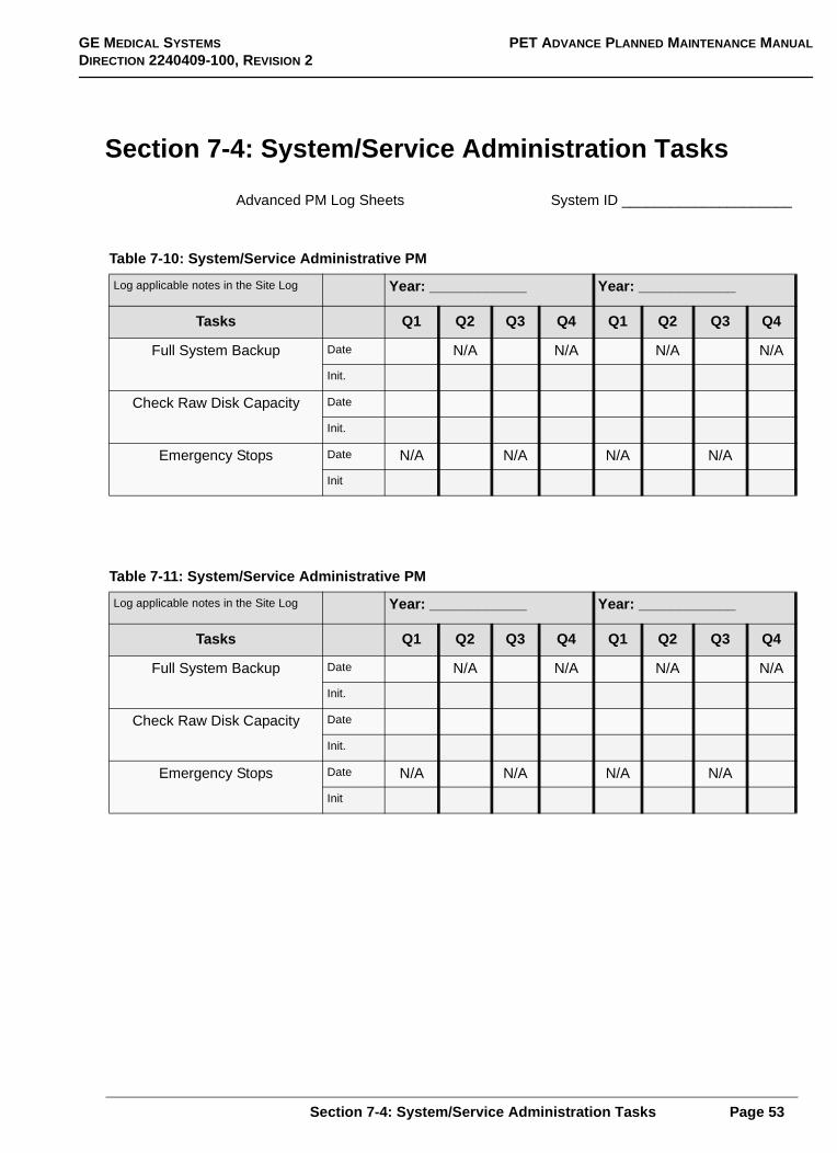
Section 7-4: System/Service Administration Tasks
Advanced PM Log Sheets System ID _____________________
Table 7-10: System/Service Administrative PM
Log applicable notes in the Site Log Year: ____________ Year: ____________
Tasks Q1 Q2 Q3 Q4 Q1 Q2 Q3 Q4
Full System Backup Date N/A N/A N/A N/A
Init.
Check Raw Disk Capacity Date
Init.
Emergency Stops Date N/A N/A N/A N/A
Init
Table 7-11: System/Service Administrative PM
Log applicable notes in the Site Log Year: ____________ Year: ____________
Tasks Q1 Q2 Q3 Q4 Q1 Q2 Q3 Q4
Full System Backup Date N/A N/A N/A N/A
Init.
Check Raw Disk Capacity Date
Init.
Emergency Stops Date N/A N/A N/A N/A
Init
Section 7-4: System/Service Administration Tasks Page 53

PET ADVANCE PLANNED MAINTENANCE MANUAL GE MEDICAL SYSTEMS
DIRECTION 2240409-100, REVISION 2
System/Services Administration Notes and Comments:
Page 54 Section 7-4: System/Service Administration Tasks

GE MEDICAL SYSTEMS PET ADVANCE PLANNED MAINTENANCE MANUAL
DIRECTION 2240409-100, REVISION 2
Table 7-12: System/Service Administrative PM
Log applicable notes in the Site Log Year: ____________ Year: ____________
Tasks Q1 Q2 Q3 Q4 Q1 Q2 Q3 Q4
Full System Backup Date N/A N/A N/A N/A
Init.
Check Raw Disk Capacity Date
Init.
Emergency Stops Date N/A N/A N/A N/A
Init
Table 7-13: System/Service Administrative PM
Log applicable notes in the Site Log Year: ____________ Year: ____________
Tasks Q1 Q2 Q3 Q4 Q1 Q2 Q3 Q4
Full System Backup Date N/A N/A N/A N/A
Init.
Check Raw Disk Capacity Date
Init.
Emergency Stops Date N/A N/A N/A N/A
Init
Section 7-4: System/Service Administration Tasks Page 55

PET ADVANCE PLANNED MAINTENANCE MANUAL GE MEDICAL SYSTEMS
DIRECTION 2240409-100, REVISION 2
System/Services Administration Notes and Comments:
Page 56 Section 7-4: System/Service Administration Tasks

GE MEDICAL SYSTEMS PET ADVANCE PLANNED MAINTENANCE MANUAL
DIRECTION 2240409-100, REVISION 2
Table 7-14: System/Service Administrative PM
Log applicable notes in the Site Log Year: ____________ Year: ____________
Tasks Q1 Q2 Q3 Q4 Q1 Q2 Q3 Q4
Full System Backup Date N/A N/A N/A N/A
Init.
Check Raw Disk Capacity Date
Init.
Emergency Stops Date N/A N/A N/A N/A
Init
Table 7-15: System/Service Administrative PM
Log applicable notes in the Site Log Year: ____________ Year: ____________
Tasks Q1 Q2 Q3 Q4 Q1 Q2 Q3 Q4
Full System Backup Date N/A N/A N/A N/A
Init.
Check Raw Disk Capacity Date
Init.
Emergency Stops Date N/A N/A N/A N/A
Init
Section 7-4: System/Service Administration Tasks Page 57

PET ADVANCE PLANNED MAINTENANCE MANUAL GE MEDICAL SYSTEMS
DIRECTION 2240409-100, REVISION 2
System/Services Administration Notes and Comments:
Page 58 Section 7-4: System/Service Administration Tasks

GE MEDICAL SYSTEMS PET ADVANCE PLANNED MAINTENANCE MANUAL
DIRECTION 2240409-100, REVISION 2
Section 7-5: Gantry/Table PM Log Sheets
Advanced PM Log Sheets System ID _____________________
Table 7-16: Gantry/Table PM
Log applicable notes in the Site Log Year: ____________ Year: ____________
Tasks Q1 Q2 Q3 Q4 Q1 Q2 Q3 Q4
Inspect Gantry Fans (5) Date
Init.
Clean REDDOG Filters (2) Date
Init.
Check Gantry Lamps and Displays Date
Init.
Clean and Inspect Transmission Ring BeltEvery 6 months
Date N/A N/A N/A N/A
Init
Lubricate the CollimatorOnce each year
Date N/A N/A N/A N/A N/A N/A
Init
Lubricate the Gripper Date
Init
Test the Source Load Function Date
Init
Check and Clean the Table Base Date N/A N/A N/A N/A
Init.
Check and Clean the Cradle Area Date N/A N/A N/A N/A
Init
Check Patient Safety Grounds Date N/A N/A N/A N/A
Init
Section 7-5: Gantry/Table PM Log Sheets Page 59

PET ADVANCE PLANNED MAINTENANCE MANUAL GE MEDICAL SYSTEMS
DIRECTION 2240409-100, REVISION 2
Gantry/Table PM Notes and Comments:
Page 60 Section 7-5: Gantry/Table PM Log Sheets

GE MEDICAL SYSTEMS PET ADVANCE PLANNED MAINTENANCE MANUAL
DIRECTION 2240409-100, REVISION 2
Table 7-17: Gantry/Table PM
Log applicable notes in the Site Log Year: ____________ Year: ____________
Tasks Q1 Q2 Q3 Q4 Q1 Q2 Q3 Q4
Inspect Gantry Fans (5) Date
Init.
Clean REDDOG Filters (2) Date
Init.
Check Gantry Lamps and Displays Date
Init.
Clean and Inspect Transmission Ring BeltEvery 6 months
Date N/A N/A N/A N/A
Init
Lubricate the CollimatorOnce each year
Date N/A N/A N/A N/A N/A N/A
Init
Lubricate the Gripper Date
Init
Test the Source Load Function Date
Init
Check and Clean the Table Base Date N/A N/A N/A N/A
Init.
Check and Clean the Cradle Area Date N/A N/A N/A N/A
Init
Check Patient Safety Grounds Date N/A N/A N/A N/A
Init
Section 7-5: Gantry/Table PM Log Sheets Page 61

PET ADVANCE PLANNED MAINTENANCE MANUAL GE MEDICAL SYSTEMS
DIRECTION 2240409-100, REVISION 2
Gantry/Table PM Notes and Comments:
Page 62 Section 7-5: Gantry/Table PM Log Sheets

GE MEDICAL SYSTEMS PET ADVANCE PLANNED MAINTENANCE MANUAL
DIRECTION 2240409-100, REVISION 2
Table 7-18: Gantry/Table PM
Log applicable notes in the Site Log Year: ____________ Year: ____________
Tasks Q1 Q2 Q3 Q4 Q1 Q2 Q3 Q4
Inspect Gantry Fans (5) Date
Init.
Clean REDDOG Filters (2) Date
Init.
Check Gantry Lamps and Displays Date
Init.
Clean and Inspect Transmission Ring BeltEvery 6 months
Date N/A N/A N/A N/A
Init
Lubricate the CollimatorOnce each year
Date N/A N/A N/A N/A N/A N/A
Init
Lubricate the Gripper Date
Init
Test the Source Load Function Date
Init
Check and Clean the Table Base Date N/A N/A N/A N/A
Init.
Check and Clean the Cradle Area Date N/A N/A N/A N/A
Init
Check Patient Safety Grounds Date N/A N/A N/A N/A
Init
Section 7-5: Gantry/Table PM Log Sheets Page 63

PET ADVANCE PLANNED MAINTENANCE MANUAL GE MEDICAL SYSTEMS
DIRECTION 2240409-100, REVISION 2
Gantry/Table PM Notes and Comments:
Page 64 Section 7-5: Gantry/Table PM Log Sheets

GE MEDICAL SYSTEMS PET ADVANCE PLANNED MAINTENANCE MANUAL
DIRECTION 2240409-100, REVISION 2
Table 7-19: Gantry/Table PM
Log applicable notes in the Site Log Year: ____________ Year: ____________
Tasks Q1 Q2 Q3 Q4 Q1 Q2 Q3 Q4
Inspect Gantry Fans (5) Date
Init.
Clean REDDOG Filters (2) Date
Init.
Check Gantry Lamps and Displays Date
Init.
Clean and Inspect Transmission Ring BeltEvery 6 months
Date N/A N/A N/A N/A
Init
Lubricate the CollimatorOnce each year
Date N/A N/A N/A N/A N/A N/A
Init
Lubricate the Gripper Date
Init
Test the Source Load Function Date
Init
Check and Clean the Table Base Date N/A N/A N/A N/A
Init.
Check and Clean the Cradle Area Date N/A N/A N/A N/A
Init
Check Patient Safety Grounds Date N/A N/A N/A N/A
Init
Section 7-5: Gantry/Table PM Log Sheets Page 65

PET ADVANCE PLANNED MAINTENANCE MANUAL GE MEDICAL SYSTEMS
DIRECTION 2240409-100, REVISION 2
Gantry/Table PM Notes and Comments:
Page 66 Section 7-5: Gantry/Table PM Log Sheets

GE MEDICAL SYSTEMS PET ADVANCE PLANNED MAINTENANCE MANUAL
DIRECTION 2240409-100, REVISION 2
Table 7-20: Gantry/Table PM
Log applicable notes in the Site Log Year: ____________ Year: ____________
Tasks Q1 Q2 Q3 Q4 Q1 Q2 Q3 Q4
Inspect Gantry Fans (5) Date
Init.
Clean REDDOG Filters (2) Date
Init.
Check Gantry Lamps and Displays Date
Init.
Clean and Inspect Transmission Ring BeltEvery 6 months
Date N/A N/A N/A N/A
Init
Lubricate the CollimatorOnce each year
Date N/A N/A N/A N/A N/A N/A
Init
Lubricate the Gripper Date
Init
Test the Source Load Function Date
Init
Check and Clean the Table Base Date N/A N/A N/A N/A
Init.
Check and Clean the Cradle Area Date N/A N/A N/A N/A
Init
Check Patient Safety Grounds Date N/A N/A N/A N/A
Init
Section 7-5: Gantry/Table PM Log Sheets Page 67

PET ADVANCE PLANNED MAINTENANCE MANUAL GE MEDICAL SYSTEMS
DIRECTION 2240409-100, REVISION 2
Gantry/Table PM Notes and Comments:
Page 68 Section 7-5: Gantry/Table PM Log Sheets

GE MEDICAL SYSTEMS PET ADVANCE PLANNED MAINTENANCE MANUAL
DIRECTION 2240409-100, REVISION 2
Table 7-21: Gantry/Table PM
Log applicable notes in the Site Log Year: ____________ Year: ____________
Tasks Q1 Q2 Q3 Q4 Q1 Q2 Q3 Q4
Inspect Gantry Fans (5) Date
Init.
Clean REDDOG Filters (2) Date
Init.
Check Gantry Lamps and Displays Date
Init.
Clean and Inspect Transmission Ring BeltEvery 6 months
Date N/A N/A N/A N/A
Init
Lubricate the CollimatorOnce each year
Date N/A N/A N/A N/A N/A N/A
Init
Lubricate the Gripper Date
Init
Test the Source Load Function Date
Init
Check and Clean the Table Base Date N/A N/A N/A N/A
Init.
Check and Clean the Cradle Area Date N/A N/A N/A N/A
Init
Check Patient Safety Grounds Date N/A N/A N/A N/A
Init
Section 7-5: Gantry/Table PM Log Sheets Page 69

PET ADVANCE PLANNED MAINTENANCE MANUAL GE MEDICAL SYSTEMS
DIRECTION 2240409-100, REVISION 2
Gantry/Table PM Notes and Comments:
Page 70 Section 7-5: Gantry/Table PM Log Sheets

GE MEDICAL SYSTEMS PET ADVANCE PLANNED MAINTENANCE MANUAL
DIRECTION 2240409-100, REVISION 2
Section 7-6: Electronics Cabinet PM Log Sheets
Note: If the PET Advance system has the G2 version of the Electronics Cabinet, skip the firsttask, fill the Quarterly blanks with "N/A", and initial.
Advanced PM Log Sheets System ID _____________________
Table 7-22: Electronics Cabinet Checks
Log applicable notes in the Site Log Year: ____________ Year: ____________
Tasks Q1 Q2 Q3 Q4 Q1 Q2 Q3 Q4
Clean the G1 Cabinet Filters Date
Init.
Check the G1 and G2 Cabinet fans Date
Init.
Table 7-23: Electronics Cabinet Checks
Log applicable notes in the Site Log Year: ____________ Year: ____________
Tasks Q1 Q2 Q3 Q4 Q1 Q2 Q3 Q4
Clean the G1 Cabinet Filters Date
Init.
Check the G1 and G2 Cabinet fans Date
Init.
Table 7-24: Electronics Cabinet Checks
Log applicable notes in the Site Log Year: ____________ Year: ____________
Tasks Q1 Q2 Q3 Q4 Q1 Q2 Q3 Q4
Clean the G1 Cabinet Filters Date
Init.
Check the G1 and G2 Cabinet fans Date
Init.
Section 7-6: Electronics Cabinet PM Log Sheets Page 71

PET ADVANCE PLANNED MAINTENANCE MANUAL GE MEDICAL SYSTEMS
DIRECTION 2240409-100, REVISION 2
Electronics Cabinets PM Notes and Comments:
Page 72 Section 7-6: Electronics Cabinet PM Log Sheets

GE MEDICAL SYSTEMS PET ADVANCE PLANNED MAINTENANCE MANUAL
DIRECTION 2240409-100, REVISION 2
Table 7-25: Electronics Cabinet Checks
Log applicable notes in the Site Log Year: ____________ Year: ____________
Tasks Q1 Q2 Q3 Q4 Q1 Q2 Q3 Q4
Clean the G1 Cabinet Filters Date
Init.
Check the G1 and G2 Cabinet fans Date
Init.
Table 7-26: Electronics Cabinet Checks
Log applicable notes in the Site Log Year: ____________ Year: ____________
Tasks Q1 Q2 Q3 Q4 Q1 Q2 Q3 Q4
Clean the G1 Cabinet Filters Date
Init.
Check the G1 and G2 Cabinet fans Date
Init.
Table 7-27: Electronics Cabinet Checks
Log applicable notes in the Site Log Year: ____________ Year: ____________
Tasks Q1 Q2 Q3 Q4 Q1 Q2 Q3 Q4
Clean the G1 Cabinet Filters Date
Init.
Check the G1 and G2 Cabinet fans Date
Init.
Section 7-6: Electronics Cabinet PM Log Sheets Page 73

PET ADVANCE PLANNED MAINTENANCE MANUAL GE MEDICAL SYSTEMS
DIRECTION 2240409-100, REVISION 2
Electronics Cabinets PM Notes and Comments:
Page 74 Section 7-6: Electronics Cabinet PM Log Sheets

GE MEDICAL SYSTEMS PET ADVANCE PLANNED MAINTENANCE MANUAL
DIRECTION 2240409-100, REVISION 2
Section 7-7: Workstation and Peripheral PM Log Sheets
Advanced PM Log Sheets System ID ____________________
Table 7-28: Workstations and Peripheral Devices
Log applicable notes in the Site Log Year: ____________ Year: ____________
Tasks Q1 Q2 Q3 Q4 Q1 Q2 Q3 Q4
Check OWS & AWS Air Flow Date
Init.
Check SCSI Enclosure Date
Init
Check Laser Cam Filmer* Date
Init
Check Color Printer* Date
Init
* Follow Vender Manual instructions
Table 7-29: Workstations and Peripheral Devices
Log applicable notes in the Site Log Year: ____________ Year: ____________
Tasks Q1 Q2 Q3 Q4 Q1 Q2 Q3 Q4
Check OWS & AWS Air Flow Date
Init.
Check SCSI Enclosure Date
Init
Check Laser Cam Filmer* Date
Init
Check Color Printer* Date
Init
* Follow Vender Manual instructions
Section 7-7: Workstation and Peripheral PM Log Sheets Page 75

PET ADVANCE PLANNED MAINTENANCE MANUAL GE MEDICAL SYSTEMS
DIRECTION 2240409-100, REVISION 2
Peripheral Device PM Notes and Comments:
Page 76 Section 7-7: Workstation and Peripheral PM Log Sheets

GE MEDICAL SYSTEMS PET ADVANCE PLANNED MAINTENANCE MANUAL
DIRECTION 2240409-100, REVISION 2
Table 7-30: Workstations and Peripheral Devices
Log applicable notes in the Site Log Year: ____________ Year: ____________
Tasks Q1 Q2 Q3 Q4 Q1 Q2 Q3 Q4
Check OWS & AWS Air Flow Date
Init.
Check SCSI Enclosure Date
Init
Check Laser Cam Filmer* Date
Init
Check Color Printer* Date
Init
* Follow Vender Manual instructions
Table 7-31: Workstations and Peripheral Devices
Log applicable notes in the Site Log Year: ____________ Year: ____________
Tasks Q1 Q2 Q3 Q4 Q1 Q2 Q3 Q4
Check OWS & AWS Air Flow Date
Init.
Check SCSI Enclosure Date
Init
Check Laser Cam Filmer* Date
Init
Check Color Printer* Date
Init
* Follow Vender Manual instructions
Section 7-7: Workstation and Peripheral PM Log Sheets Page 77

PET ADVANCE PLANNED MAINTENANCE MANUAL GE MEDICAL SYSTEMS
DIRECTION 2240409-100, REVISION 2
Workstation and Peripheral Device PM Notes and Comments:
Page 78 Section 7-7: Workstation and Peripheral PM Log Sheets

GE MEDICAL SYSTEMS PET ADVANCE PLANNED MAINTENANCE MANUAL
DIRECTION 2240409-100, REVISION 2
Table 7-32: Workstations and Peripheral Devices
Log applicable notes in the Site Log Year: ____________ Year: ____________
Tasks Q1 Q2 Q3 Q4 Q1 Q2 Q3 Q4
Check OWS & AWS Air Flow Date
Init.
Check SCSI Enclosure Date
Init
Check Laser Cam Filmer* Date
Init
Check Color Printer* Date
Init
* Follow Vender Manual instructions
Table 7-33: Workstations and Peripheral Devices
Log applicable notes in the Site Log Year: ____________ Year: ____________
Tasks Q1 Q2 Q3 Q4 Q1 Q2 Q3 Q4
Check OWS & AWS Air Flow Date
Init.
Check SCSI Enclosure Date
Init
Check Laser Cam Filmer* Date
Init
Check Color Printer* Date
Init
* Follow Vender Manual instructions
Section 7-7: Workstation and Peripheral PM Log Sheets Page 79

PET ADVANCE PLANNED MAINTENANCE MANUAL GE MEDICAL SYSTEMS
DIRECTION 2240409-100, REVISION 2
Workstation and Peripheral Device PM Notes and Comments:
Page 80 Section 7-7: Workstation and Peripheral PM Log Sheets


GE MEDICAL SYSTEMSGE MEDICAL SYSTEMS-AMERICAS: FAX 262.544.3384P.O. BOX 414; MILWAUKEE, WISCONSIN 53201-0414, U.S.A.
GE MEDICAL SYSTEMS-EUROPE: FAX 33.1.40.93.33.33PARIS, FRANCE
GE MEDICAL SYSTEMS-ASIA: FAX 65.291.700682