technical bulletin page 11 of 14 setup this section provides instructions for entering the offset...
TRANSCRIPT

TB-2017198-BW Page 1 of 14
Technical Bulletin © 2017 Southern Technologies Corporation (STC). All rights reserved.
Bulletin Number: TB-2017198-BW01 Date Published: 07/17/2017 Summary: Instructions for mounting, aligning and setting up the 2100-696 Frauscher Zero-Speed Dual Gating Assembly for use with the SmartScan NG².
☐ Critical (Affects safe operation of system) ☐ Informational
Distribution List:
SmartScan NG² / Frauscher Zero-Speed Transducers – Installation & Setup
Contents
2100-696 Frauscher Zero-Speed Dual Gating Assembly .................................................. 2
Tools Required for Installation ........................................................................................... 3
Default Configuration ........................................................................................................ 3
Removal of Mounting Hardware ........................................................................................ 4
Locate Bracket on Foot of Rail .......................................................................................... 4
Installation of Transducer Assembly.................................................................................. 5
Vertical Adjustment ........................................................................................................... 5
Horizontal Adjustment ....................................................................................................... 6
Connection of Transducer Cables ..................................................................................... 6
Measuring the Location of the Bearing Scanners .............................................................. 7
Method for Transferring a Location to the Opposite Rail ................................................... 7
Measuring the Location of the Wheel Scanners ................................................................ 8
Wiring ................................................................................................................................ 9
Automated Adjustment ................................................................................................... 10
Troubleshooting After Automated Adjustment ................................................................. 10
Occupancy Detection ...................................................................................................... 10
Setup .............................................................................................................................. 11
Verifying Virtual Gate Operation ...................................................................................... 12
Simulate Passing Wheels................................................................................................ 13
Preventive Maintenance .................................................................................................. 13
Troubleshooting Transducer System............................................................................... 14
Checking the Sensor for Correct Current Flow ................................................................ 14

TB-2017198-BW Page 2 of 14
2100-696 Frauscher Zero-Speed Dual Gating Assembly
The Frauscher Zero-Speed Dual Gating Wheel Detector Assembly is a rail-mounted device that generates precision wheel timing signals for the SmartScan NG² Defect Detector. The combination of inductive operating principles and the robust design of the RSR110 sensors guarantee high reliability, even when subjected to extreme mechanical, electromagnetic, climatic and environmental working conditions.

TB-2017198-BW Page 3 of 14
Tools Required for Installation
11/16” Socket
7/8” Socket
7/8” Wrench
1-1/2” Socket
Torque Wrench (foot-pound)
External Retaining Ring Pliers
6mm Hex Key Wrench
Straight Slot Screwdriver approximately 1/8” wide.
Wire cutters
Wire Strippers
Default Configuration
The 2100-696 Double Gating Transducer brackets are pre-adjusted for 132LB RE rails.

TB-2017198-BW Page 4 of 14
Removal of Mounting Hardware
Locate Bracket on Foot of Rail

TB-2017198-BW Page 5 of 14
Installation of Transducer Assembly
Vertical Adjustment
Loosen the two 7/8” nuts securing the Adjustable Mounting Plate and move the transducers into adjustment, referring to the dimensions above. Tighten to 20 ft./lbs.

TB-2017198-BW Page 6 of 14
Horizontal Adjustment
Connection of Transducer Cables

TB-2017198-BW Page 7 of 14
Measuring the Location of the Bearing Scanners
Note: When using the Frauscher Gating Transducers, you are not limited to mounting the Bearing Scanners and Wheel Scanners in specific locations as with the Magnetic Transducers. Centering the scanners in the crib is recommended for convenient access and isolation from vibrating crossties. Always aim the view of the Bearing Scanners toward the Frauscher Gating Transducers. The OFFSET dimension cannot be greater than 200-inches. However, locate the Bearing Scanners in the next crib over from the Gating Transducer whenever possible to maintain a standard installation configuration.
Obtain the OFFSET dimension as illustrated above for the Bearing Scanner mounted on the same rail with the Gating Transducers.
Using the method below, transfer the location from the center of Gating Transducer mounting bracket to the other rail, to establish a reference point for measuring in the next step.
Obtain the OFFSET dimension for the second Bearing Scanner by measuring from the point that you transferred to the center of the Bearing Scanner mounting bracket.
Write down both OFFSET values. They are entered, to the nearest inch, in the
Setup section of this document.
Method for Transferring a Location to the Opposite Rail
Refer to the illustration below.
1. At equal distances between the rails place a mark on the fourth crosstie from the point to be transferred, as represented in the figure below between the two D1 dimensions.
2. Measure from the mark that you made on the crosstie to the point on the rail that you need to transfer to the other rail. Use this dimension in the next step.
3. Measure the same distance from to the mark in the center of the crosstie to the “Corresponding Location” on the other rail. Mark the corresponding location on the rail.
OFFSET
BEARING SCANNER 2100-696 FRAUSCHER GATING
TRANSDUCER (BRACKET ASM.)

TB-2017198-BW Page 8 of 14
Measuring the Location of the Wheel Scanners
Skip this step if you are not using Wheel Scanners.
First Rail: The Wheel Scanner located on the same rail with the Gating Transducers, mounts in the crib on either side of Gating Transducer Assembly.
o If the closest crib to the Gating Transducers is not available, mount the Wheel Scanner in the next crib to either side of the Gating Transducers. Do not exceed 200-inches from the center of the Gating Transducer mounting bracket to the center of the Wheel Scanner bracket.
Second Rail: Mount the Wheel Scanner on the opposite rail from the Gating Transducers at a location directly across from Gating Transducers, if possible. Optionally this Wheel Scanner can be mounted up to 200-inches in either direction.
o If you have not already done so, transfer the location from the center of the Gating Transducers to this rail.
o Measure from the mark that you moved from the first rail to the center of the Wheel Scanner mounting bracket to get the OFFSET dimension for the second Wheel Scanner. If the wheel scanner mounts directly across from the Gating Transducers, this dimension is zero.
Write down the OFFSET dimensions for each wheel scanner to be entered in the Setup
section of this document.
TB-2017198-BW Page 9 of 14
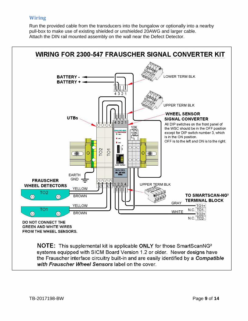
Wiring
Run the provided cable from the transducers into the bungalow or optionally into a nearby pull-box to make use of existing shielded or unshielded 20AWG and larger cable. Attach the DIN rail mounted assembly on the wall near the Defect Detector.

TB-2017198-BW Page 10 of 14
Automated Adjustment
The Automated Adjustment function nulls out any influence of the rail and mounting hardware located in the area of the sensor. Run the Automated Adjustment process after installation and after making physical changes to transducer alignment. Tie plates, track spikes, rail anchors, rail clips – and similar hardware – used in the area under the transducer does not interfere with the operation. Run the Auto Adjustment function after removing or adding metal hardware in the vicinity of the transducers.
Follow these steps to run the Auto Adjustment feature.
1. Connect transducers to the WSC by following the wiring diagram on the previous page.
2. Apply power to the system.
3. Confirm that the wheel sensors are mounted correctly, and ready for use.
4. Locate the DIP switches on the WSC and move DIP switch number 8 to the ON position for between two and six seconds.
5. Return DIP switch number 8 to the OFF position. As a result, the Sys1 and Sys2 LEDs should light up indicating that the Automated Adjustment function has started.
The WSC adjusts both wheel sensors simultaneously requiring up to forty seconds.
The Sys1 and Sys2 LEDs turn off when the session finishes, indicating successful calibration.
A blinking Sys LED after the calibration process means that the associated sensor(s) did not successfully adjust.
Troubleshooting After Automated Adjustment
If one or both sensors failed to adjust correctly, check the following items.
Wheel sensor alignment
Wiring
Possible faulty wheel sensor
Possible calibration error — run the calibration function again.
Occupancy Detection
After successful automated adjustment of both transducers, use the PB200 Test Wheel Sensor Target (pictured right) to test for occupancy detection as follows.
1. Place the Sensor Target on the Sys1 sensor of transducer TO1. Align the notch on the bottom of the Sensor Target with the hash mark on the top of the SYS1 transducer. The Sys1 LED located on the WSC and the TO1 LED on the SmartScan NG² should light up.
2. Repeat the procedure with transducer TO2. The Sys2 LED on the WSC and the TO2 LED on the SmartScan NG² should light up.
Wheel Signal Converter (WSC)

TB-2017198-BW Page 11 of 14
Setup
This section provides instructions for entering the OFFSET dimensions into the “Transducer / Scanner Offset” menu of SmartScan NG².
Note: The setup menus referenced at the time of writing are available by way of the RS-232 interface via COM-1 or through a Telnet connection.
Drilling Down to the “Transducer / Scanner Offset” menu.
SmartSCAN NG2, MP/KP:1234.6, Track:Track 2
05/24/2017 13:32:57, 13.9V, 65°F
Transducer / Scanner Offset Menu
----------------------------------------
[A] - Transducer Type ........................ Frauscher
[B] - Rail Size ............................ 136 (67.46)
[C] - East Rail Scanner Offset .......... 0 inches (TO2)
[D] - West Rail Scanner Offset .......... 0 inches (TO2)
[E] - East Wheel Scanner Offset ......... 0 inches (TO1)
[F] - West Wheel Scanner Offset ......... 0 inches (TO1)
[X] – Exit
1. Press the A key until “Frauscher” is selected. 2. Press the B key for a list of rail sizes and choose the one matching the size at your
location. 3. For items, C, D, E, and F, enter the measurements representing the associated
scanner’s OFFSET dimension – to the nearest inch – and reply to questions asking for the closest Gating Transducer to the scanner — TO1 or TO2.
4. Back out of the menus by pressing the X key in each menu. Type “setup” when asked to do so, if you wish to save your entries.
Main Menu
Setup Menu
Equipment Settings
Advanced

TB-2017198-BW Page 12 of 14
Verifying Virtual Gate Operation
The data that you enter into the “Transducer / Scanner Offset” menu places the Virtual Gate areas at each of the scanners positioned at various distances from the Gating Transducers.
The test mode described in this section helps to double check that the OFFSET measurements and associated entries are correct. The most accurate method to verify OFFSET is the use of a tape measure following the previous instructions in this document.
Virtual Gate: The SmartScan NG² allows you to position the wheel and Bearing Scanners up to two hundred inches to either side of the center of the Gating Transducer mounting bracket. To ensure that all wheel and bearing temperatures are measured, the system records a continuous stream of data samples from each scanner allowing it to provide bearing and wheel temperature measurements from scanners aimed outside of the area defined by the Gating Transducers. Synchronizing the scanner’s temperature measurements to the Gating Transducer’s wheel signals is done after a given axle crosses the Gating Transducers. At that time the correct heat samples are picked out based on the speed and direction of the axle, and the offset position of the scanner.
Drilling Down to the “Virtual Gate Test” menu.
Select a scanner:
[1] - East Rail
[2] - West Rail
[3] - East Wheel
[4] - West Wheel
Main Menu
System Functions Menu
Virtual Gate Test
TB-2017198-BW Page 13 of 14
Simulate Passing Wheels
While in Virtual Gate Test Mode, the goal is to simulate a wheel that passes over the Gating Transducers and then continues moving to the scanner under test. The system notifies you when the simulated wheel is in the Virtual Gate area by cycling the shutters. The following steps describe how to use the Virtual Gate Test Mode.
1. From the Virtual Gate Test Mode menu, select a scanner in which you want to see its Virtual Gate position.
2. Swipe across the Gating Transducers with a metal object in the direction of the scanner under test. Maintain a speed faster than 1.6 seconds between sensors.
3. Swipe across the sensors again. However, this time continue moving the metal object to the scanner under test while maintaining a constant speed.
4. The shutters rapidly cycle one time to indicate when the system is looking for heat in the virtual window located at the scanner, which should be at the time that the metal object (simulated axle) passes the scanner. If the shutters do not cycle, the entry for closest transducer (TO1 or TO2) may be incorrect.
5. Repeat step number four, simulating various axle speeds, as needed to confirm settings.
The test mode runs for two minutes before timing out. Otherwise, any keypress ends the session. Rapid shutter flutter is an indication that two minutes have expired and the test has ended automatically. The event log records a canceled train at the end of the testing session.
Preventive Maintenance
Periodically perform the following maintenance work, adapted to the conditions of the track, but at least every two years.
A visual and mechanical check.
Check wheel sensor for excessive dirt build-up.
Check wheel sensor for external mechanical damages.
Check mounting bracket for correct fit.
Check rubber conduit tube for damage.
Check cable connection terminals for correct fit.

TB-2017198-BW Page 14 of 14
Troubleshooting Transducer System
The following instructions provide methods for locating problems in the Zero-Speed transducer system.
PWR LED Off
MEANING POSSIBLE SOLUTIONS
No power supply Apply power supply
Wrong polarity Reverse polarity
Open fuse Replace WSC
Sys1 / Sys2 LED Flashes Slowly
MEANING POSSIBLE SOLUTIONS
WSC did not initiate Automated Adjustment correctly
Run Automated Adjustment Function
Wire break in the wheel sensor circuit Check wiring for open circuit
Overcurrent in wheel sensor circuit Check wiring for short circuit
Checking the Sensor for Correct Current Flow
There are approximately 5 milliamps of current flow through the sensor when it is working properly, and it is not sensing a target.
Tools Needed:
A digital Volt/Ohm meter with a milliamp setting.
Small bladed straight slot screwdriver approximately 1/8” wide.
Connect the ammeter in series with the yellow transducer wire as follows.
1. Verify that the sensor is powered up by measuring the voltage across the brown (positive) and yellow (negative) sensor wires going to the WSC for 24 Volts DC.
2. Set the digital voltmeter to measure DC milliamperes and unplug the red meter lead from the voltage jack and plug it into the milliamps jack on the meter.
3. Remove the yellow sensor wire from the WSC and replace it with the black meter probe.
4. Touch the red meter probe to the yellow sensor wire that you removed from the WSC in the last step. The milliamp meter is now in series with the negative sensor wire.
5. Check for positive 5 milliamps, within a tolerance of +/- 5%. 6. The current measurement should go down as a metal target comes near the sensor.
If the current flow is not correct, try the following.
Run the Automated Adjustment function.
Check for breaks in the sensor wiring. Replace sensor.