technical note - tn 029:2017 - transport for nsw · technical note - tn 029:2017 subject: update to...
TRANSCRIPT
Technical Note - TN 029: 2017
© State of NSW through Transport for NSW 2017 Page 1 of 1
Technical Note - TN 029:2017
Subject: Update to SPG 0705 Construction of Cable Routes and Signalling Civil Works, version 1.17
For queries regarding this document [email protected]
www.asa.transport.nsw.gov.au
Issued date: 02 August 2017
Effective date: 02 August 2017
This technical note has been issued by the Asset Standards Authority (ASA) to notify the
following amendments to SPG 0705 Construction of Cable Routes and Signalling Civil Works,
version 1.17:
• Delete Section 18.2 Balise Tail Cable in its entirety; refer to SPG 0706 Installation of
Trackside Equipment, version 2.3 for information on balise tail cable requirements.
• Figure 3, Figure 4 and Figure 5 in Appendix C ATP Installation Drawings are for reference
purpose only and are no longer required to uniquely describe the ATP installations.
These drawings will be removed in the next version of SPG 0705.
The installation of ATP equipment shall comply with the relevant standards dealing with that
equipment.
Authorisation:
Technical content prepared by
Checked and approved by
Interdisciplinary coordination checked by
Authorised for release
Signature
Date
Name Eric Edwards Peter McGregor Jason R Gordon Jagath Peiris
Position Senior Signal Engineer
Lead Signals and Control Systems Engineer
Chief Engineer Director Network Standards and Services

Technical Note - TN 065:2016
Technical Note - TN 065: 2016
Subject: Update to SPG 0705 – Amendment to the definition of the term 'high voltage'
Issued date: 03 November 2016
Effective date: 03 November 2016
For queries regarding this document [email protected]
www.asa.transport.nsw.gov.au
This technical note is issued by the Asset Standards Authority (ASA) to update the requirements
of SPG 0705 Construction of Cable Routes and Signalling Civil Works, version 1.17. The updates
are the result of the amendment to the definition of the term 'high voltage'.
1. New high voltage definitionThe definition of the term high voltage in SPG 0705 shall be as follows:
"Any voltage over 1000 V ac or 1500 V dc."
2. Amendments and clarification to SPG 0705The following sections of SPG 0705 shall be amended except for Section 17.3 where clarification
is instead provided:
Section 1.3 Definitions
Replace the definition for the term 'High voltage' with the following:
"Any voltage over 1000 V ac or 1500 V dc."
Replace the definition for the term 'Low voltage' with the following:
"Any voltage that is lower than high voltage."
Add the following text at the end of the definition for 'Main cables':
"This includes the cables used for the reticulation of the signalling supply."
© State of NSW through Transport for NSW Page 1 of 2
Technical Note - TN 065:2016
Section 6.5 Earth Cables and Wires in Trenches
Replace the 6th bullet point in Section 6.5 with the following:
• "Broken for 20 metres either side of high voltage earths to prevent fault current being
collected and directed along the signalling cables to the signalling location. High voltage
earths are the earths found at 11KV or higher power poles, HV ac substations, traction
substations and sectioning huts."
Section 12.1 General
The last paragraph in Section 12.1 shall be replaced with the following:
"Installation of high voltage power cables in pits with low voltage and signalling cables shall
not be permitted."
Section 17.3 High Voltage Impulse and Audio Frequency Track Circuits
The following clarification is provided for Section 17.3:
The use of the term 'high voltage impulse' is a descriptive term for this particular type of track
circuit. The output of the transmitter and receiver input voltages can be as high as 600 V peak
and so by definition, can be classified as low voltage. Cable routing practices will not change as a
result of this change in definition.
21.1.4 Separation
Replace the fifth paragraph of Section 21.1.4 with the following:
"Details on the running of high voltage cables and the segregation from other services can
be found in specifications EP 20 00 00 03 SP Above Ground Cable Installation Systems –
Selection Guide and EP 20 00 04 01 SP Cable Route Selection Guide."
Authorisation:
Technical content prepared by
Checked and approved by
Interdisciplinary coordination checked by
Authorised for release
Signature
Date
Name David Nolan Omer Saricilar Peter McGregor Graham Bradshaw
Position Principal Engineer Signalling Systems
A/Lead Engineer Signals and Control Systems
A/Chief Engineer Director Network Standards and Services
© State of NSW through Transport for NSW Page 2 of 2

Technical Note - TN 009: 2016
Technical Note - TN 009: 2016
Subject: Update to SPG 0705 Construction of Cable Routes and Signalling Civil Works
Issued date: 20 April 2016
Effective date: 20 April 2016
For queries regarding this document [email protected]
www.asa.transport.nsw.gov.au
This technical note is issued by the Asset Standards Authority to notify the following updates to
SPG 0705 Construction of Cable Routes and Signalling Civil Works, version 1.17.
The heading and the entire contents of Section 18.3 Installation of ETCS balise trunk cable
shall be replaced with the following content:
18.3 Installation of tail cable Tail cables shall be installed by utilising existing cable route infrastructure where available. An
example of a tail cable run via existing cable pit located at a signal base is outlined in
Appendix C, Figure 5.
Tail cables shall not be directly buried.
Where cables are required to cross the track, existing ULX’s shall be used where practicable.
ULX’s for tail cables shall be installed in accordance with current construction requirements. A
minimum of two by 100 mm HD orange conduits are to be installed into an open cut ULX trench.
Only one conduit is required where directional under boring is used.
Only one by 100 mm HD orange conduit is required where the existing main cable route is
extended between pits.
One 63 mm HD orange PVC conduit is required where the cable route is extended from a cable
pit up to the ETCS trackside junction box.
Where a tail cable leaves the main cable route, it shall run perpendicular to the lay of the track,
wherever possible, in accordance with the requirements of this specification. See examples in
Appendix C, Figure 3, Figure 4 and Figure 5.
© State of NSW through Transport for NSW Page 1 of 2

Technical Note - TN 009: 2016
Where orange PVC conduit appears above ground and is exposed to direct sunlight, that
exposed portion shall be painted orange in colour with water-based paint or otherwise
mechanically shielded from direct sunlight.
Section 21.3 Labelling of cables: first sentence delete the word ‘trunk’ – the sentence shall read as follows:
A form of permanent and unique identification shall be applied to both ends of every length of
cable except for ETCS cables which do not need to be identified at the trackside junction box.
Appendix C ATP installation drawings: Figure 3 Multi track showing ULX crossing with separate trunk cables – delete the word ‘trunk’ from the Caption – the Caption shall read
as follows:
Figure 3 – Multi track showing ULX crossing with separate cables
Authorisation:
Technical content prepared by
Checked and approved by
Interdisciplinary coordination checked by
Authorised for release
Signature
Name Dave Nolan Peter McGregor John Paff Graham Bradshaw
Position Principal Engineer Signalling Systems
Lead Signals and Control Systems Engineer
A/Chief Engineer Director Network Standards and Services
© State of NSW through Transport for NSW Page 2 of 2

Engi
neer
ing
Spec
ifica
tion
2
CONSTRUCTION OF CABLE ROUTES AND SIGNALLING CIVIL
WORKS
SPG 0705
Engineering Specification Signals Construction Specification
Version 1.17
Issued 8 February 2013
Reconfirmed 17 September 2019
Owner: Chief Engineer Signals and Control Systems
Approved Warwick Allison Authorised Paul Szacsvay by: Chief Engineer by: Principal Engineer
Signals and Control Systems Signal Technology
The information in this document is protected by Copyright and no part of this document may be reproduced, altered, stored or transmitted by any person without the prior consent of RailCorp.
Copyright
RailCorp accepts no liability whatsoever in relation to the use of this document by any party, and RailCorp excludes any liability which arises in any manner by the use of this document.
RailCorp makes no warranties, express or implied, that compliance with the contents of this document shall be sufficient to ensure safe systems or work or operation. It is the document user’s sole responsibility to ensure that the copy of the document it is viewing is the current version of the document as in use by RailCorp.
This document was prepared for use on the RailCorp Network only. Disclaimer
UNCONTROLLED WHEN PRINTED Page 1 of 8

RailCorp Engineering Specification — Signals — Construction Specification Construction of Cable Routes and Signalling Civil Works SPG 0705
Document Control
Vers
ion
Date Summary of change
1.0 1 May 2007 Replaced SC 11 20 00 00 SP Construction of Cable Route and Associated Civil Works v2.0 of June 1998 with some additional amendments. Reformat to RailCorp style; Section 3.4 text added with respect to ULX where sleepers have not been removed
1.1 18 June 2007 16.3 – new second Section; References to IWMP changed to Regional Representative
1.2 1 April 2008 Name change 8.1 – lining to troughing – new 4th Section; 18.1 corrected cross reference Section 2; 18.4 – New 6th Section re metal buffer stops; 18.12 – New 3rd Section about telephones near Danger Zone; 19.1 – Cable route; 19.1.7 – air line joints
1.3 7 December 2009 Amend structure gauge (Dwg 1) and add addendum to 6.3 Shared Trenches
1.4 9 February 2010 Add new chapter – Temporary Cable Routes 1.5 May 2010 Application of TMA 400 format
1.6 10 August 2010
Sect 1.2 added reference to SMS-06-GD-0378. Section 1.12 added text regarding services searches. Page 42 section 12.5 added text regarding reinforced pre-cast concrete pits manufactured to spec SPM 0123. Deleted appendix A Electric Cable Search Procedure. Renumbered appendices accordingly (ie. Appendix ‘A Inspection Report – Trenched Underline Crossing’, and appendix ‘B Drawings’. Page 46 section 14.2 Removed reference to Taree and areas north.
1.7 26 August 2010 Section 3.3 ‘Backfilling’ reference to 100mm sieve amended to 50mm. 1.8 2 November 2010 Section 11.1 re Under Track Crossings near points
1.9 4 March 2011 Reference to ESM 102 ‘Communications Outdoor Cabling Standard’ added. Reference to CCM06 amended to read AS/ACIF S009.
1.10 8 March 2011 8.1 – galvanising to be to Z600 and not Z430 or fresh surfaces protected with cold galvanising paint.
1.11 1 May 2012
1.2 – additional reference documents; 6.12 – colours of conduits; 8.5 & 9.5 – 2 expansion joints between locations of air lines; 5.1, 11.1, 12.1, 19.1 – Cable installation to comply with ACIF S009 & AS 3000; 20.1.4 – Separation to follow AS3000 & Comms cable stds; 20.1.7 Cable Joints; 22.2 provision of insulated joints Referenced Documents – add Drawing – M12 Series 1.9 – added note about M12 drawings in first paragraph. Appendix B – Drawings – amend for Dimension A – “5000” to be “electrified” region and added note to “Refer to ESC 215”
1.12 22 May 2012 Drawing in Section 6, Fig 3 – minimum separation changed from 450mm to 300mm.
1.13 3 July 2012
6.3 – delete Fig 1 and re-number Fig 2 -> Fig 1 and Fig 3 -> Fig 2; Amend vertical separation between Signalling/communications conduits and High Voltage cables to 300mm minimum, added reference to ESM 102; 5.1, 6.9, 7.1, 9.3, 11.1, 12.1, 13.2(k), 20.1 & 20.1.4 – add note about compliance with RailCorp standard ESM 102; 20.1 change AUSTEL to ACMA; 6.3 (b) & (c) amend wording to include ESM 102.
© RailCorp Page 2 of 82 Issued 8 February 2013 UNCONTROLLED WHEN PRINTED Version 1.17

RailCorp Engineering Specification — Signals — Construction Specification Construction of Cable Routes and Signalling Civil Works SPG 0705
Vers
ion
Date Summary of change
1.14 21 July 2012 1.2 & 21.3 - RailCorp std 816F changed to TMM P021
1.15 4 December 2012 3.3 – amended description of use of stabilised sand and material to SPC411
1.16 4 December 2012 Updates to RailCorp ETCS requirements 1.17 8 February 2013 Section 18.3 added text "In exception to this a diagonal bore ULX……".
© RailCorp Page 3 of 82 Issued 8 February 2013 UNCONTROLLED WHEN PRINTED Version 1.17

RailCorp Engineering Specification — Signals — Construction Specification Construction of Cable Routes and Signalling Civil Works SPG 0705
© RailCorp Page 4 of 82 Issued 8 February 2013 UNCONTROLLED WHEN PRINTED Version 1.17
Contents 1 Introduction .............................................................................................................................9
1.1 Scope.........................................................................................................................9 1.2 Referenced Documents .............................................................................................9 1.3 Definitions ................................................................................................................10 1.4 Approvals and Inspections ......................................................................................12 1.5 Environmental Considerations.................................................................................12 1.6 Responsibilities........................................................................................................12 1.7 Site Surveys.............................................................................................................13 1.8 Location of Equipment .............................................................................................13 1.9 Signal Location ........................................................................................................13 1.10 Installation Drawings................................................................................................13 1.11 Existing Equipment ..................................................................................................14 1.12 Temporary Level Crossings.....................................................................................14 1.13 Location of Services ................................................................................................15 1.14 Alternative Materials, Products or Processes..........................................................15
2 Supply Of Materials...............................................................................................................15 2.1 Material Supplied by the Regional Representative .................................................15 2.2 Materials Supplied by the Contractor ......................................................................16 2.3 Painting/Finish of Metal Surfaces ............................................................................16
3 Excavation, Boring, Backfilling And Compaction .............................................................17 3.1 Excavation ...............................................................................................................17
3.1.1 Location of Existing Services ...................................................................17 3.1.2 Preparation of Cable Route......................................................................17 3.1.3 Stability of Excavation ..............................................................................17 3.1.4 Placement of Spoil ...................................................................................17 3.1.5 Programming of work ...............................................................................18 3.1.6 Public Safety ............................................................................................18 3.1.7 Proximity to Existing Services ..................................................................18
3.2 Inspection before Backfilling....................................................................................18 3.3 Backfilling.................................................................................................................19 3.4 Compaction..............................................................................................................19
4 Concrete And Stabilised Sand.............................................................................................20 4.1 General ....................................................................................................................20 4.2 Ready Mix Concrete and Stabilised Sand...............................................................20 4.3 Site Mixed Concrete and Stabilised Sand ...............................................................20 4.4 Concrete Reinforcing ...............................................................................................21 4.5 Concrete Finish........................................................................................................21
5 Cable Route General Requirements....................................................................................21 5.1 General ....................................................................................................................21 5.2 Location of the Cable Route ....................................................................................21 5.3 Types of Cable Route ..............................................................................................22 5.4 Radius of Bends ......................................................................................................23 5.5 Underline Crossings (ULX) and Under Road Crossings (URX) ..............................23 5.6 Cable Pits ................................................................................................................23
6 Buried Cable Route (Cable Route Types 1,2,3 and 4) .......................................................23

RailCorp Engineering Specification — Signals — Construction Specification Construction of Cable Routes and Signalling Civil Works SPG 0705
© RailCorp Page 5 of 82 Issued 8 February 2013 UNCONTROLLED WHEN PRINTED Version 1.17
6.1 General ....................................................................................................................23 6.2 Depth of Cable Route ..............................................................................................23 6.3 Shared Trenches .....................................................................................................23 6.4 Protective Cover over Signalling and Communications Cables ..............................25 6.5 Earth Cables and Wires in Trenches.......................................................................25 6.6 PVC Cable Marker Tape in Trenches......................................................................26 6.7 Rock Areas ..............................................................................................................26 6.8 Cable and Pipe Plowing - Preparation of Route......................................................26 6.9 Cable Plowing - General..........................................................................................27 6.10 Cable Plowing - Demonstration ...............................................................................27 6.11 Cable Plowing - Restoration ....................................................................................28 6.12 Buried Pipes ............................................................................................................28 6.13 Pipes in High Voltage Areas....................................................................................29 6.14 Spare Buried Pipes..................................................................................................29 6.15 Pipes in Platforms and Other Paved Areas.............................................................29 6.16 Buried Cables through Water Courses....................................................................30 6.17 Cable Routes on Embankments..............................................................................30 6.18 Underground Services of Other Authorities.............................................................30 6.19 Cable Route Markers...............................................................................................31
7 Ground Level Troughing (GLT) Cable Route (Cable Route Type 5) ................................31 7.1 General ....................................................................................................................31 7.2 Troughing Route Capacity .......................................................................................31 7.3 Installation of GLT....................................................................................................32 7.4 Drainage ..................................................................................................................32 7.5 Lids ..........................................................................................................................32
8 Galvanised Steel Troughing (GST) (Cable Route Type 6).................................................33 8.1 General ....................................................................................................................33 8.2 Arrangements At or Near Overhead Wiring Structures ...........................................33 8.3 Troughing Route Capacity .......................................................................................33 8.4 Bends.......................................................................................................................34 8.5 Expansion Joints and Insulated Sections................................................................34 8.6 Mounting Brackets and Fittings ...............................................................................34 8.7 Troughing on Posts..................................................................................................34 8.8 Troughing on Railway Bridges or Viaducts..............................................................35 8.9 Troughing on Rock Faces........................................................................................35 8.10 Troughing on Walls..................................................................................................35 8.11 Troughing in Tunnels or through Underbridges with Limited
Clearances...............................................................................................................36 8.12 Steel Troughing Across Culverts, etc. .....................................................................36 8.13 Transition between GST/GLT/Buried Cable Route .................................................36 8.14 Steel Troughing Arrangements at Entries to Location Cases .................................36 8.15 Fitting of Lids ...........................................................................................................36
9 Cable ladder (cable route types 7, 8 and 9) ........................................................................37 9.1 General ....................................................................................................................37 9.2 Cable Ladder Environment......................................................................................37 9.3 Cable Ladder Capacity ............................................................................................37

RailCorp Engineering Specification — Signals — Construction Specification Construction of Cable Routes and Signalling Civil Works SPG 0705
© RailCorp Page 6 of 82 Issued 8 February 2013 UNCONTROLLED WHEN PRINTED Version 1.17
9.4 Bends.......................................................................................................................38 9.5 Joints, Expansion Joints and Insulation Gaps.........................................................38 9.6 Mounting Brackets and Fittings ...............................................................................38 9.7 Cable Ladder in Tunnels or Through Under-bridges...............................................38 9.8 Transition between Cable Ladder/Cable Ladder/GST/GLT/Buried
Route .......................................................................................................................39 9.9 Cable Ladder Arrangements at Connection to Local Cable Route and
Equipment................................................................................................................39 9.10 Cable Installation .....................................................................................................39 9.11 Cable Ladder Covers...............................................................................................39
10 Pipe Cable Route...................................................................................................................40 11 Underline And Under-road Crossings (ULX and URX)......................................................40
11.1 General ....................................................................................................................40 11.2 Depth of ULX / URX.................................................................................................41 11.3 ULX or URX by Trenching .......................................................................................41 11.4 Underline Crossings ................................................................................................41 11.5 Underroad Crossings (URX)....................................................................................42
12 Cable Pits, Cable Jointing Pits and Cable Turning Chambers.........................................42 12.1 General ....................................................................................................................42 12.2 Location of Cable Pits..............................................................................................42 12.3 Location of Cable Jointing Pits ................................................................................43 12.4 Location of Cable Turning Chambers......................................................................43 12.5 Construction of Cable Pits, Cable Jointing Pits and Cable Turning
Chambers ................................................................................................................43 12.6 Erosion of Embankments.........................................................................................45 12.7 Covers......................................................................................................................45
13 Temporary Cable Routes......................................................................................................45 13.1 Introduction ..............................................................................................................45 13.2 Design Requirements ..............................................................................................45
14 Signal And Gantry Foundations ..........................................................................................46 14.1 Location of Signal and Gantry Foundations ............................................................46 14.2 Construction of Signal Foundations.........................................................................47 14.3 Construction of Gantry Foundations........................................................................47 14.4 Backfilling and Levelling Site ...................................................................................48 14.5 Foundations Affecting Track Drainage ....................................................................48 14.6 Access to Signals and Gantries from Public Roads ................................................48
15 Location Case Foundations/Platforms ...............................................................................48 15.1 General ....................................................................................................................48 15.2 Construction of Location Case Foundations and Associated Work ........................49 15.3 Location Cases on Raised Metal Platforms.............................................................49 15.4 Steps, Ladders and Handrails .................................................................................49 15.5 Cable Entries to Location Cases .............................................................................50 15.6 Access to Location Cases .......................................................................................50
16 Communications Cable Termination Cabinet Foundations .............................................50 16.1 General ....................................................................................................................50 16.2 Construction of Foundations for Cable Termination Cabinets.................................50
17 Installation Of Track Circuit Equipment .............................................................................51

RailCorp Engineering Specification — Signals — Construction Specification Construction of Cable Routes and Signalling Civil Works SPG 0705
© RailCorp Page 7 of 82 Issued 8 February 2013 UNCONTROLLED WHEN PRINTED Version 1.17
17.1 General ....................................................................................................................51 17.2 Bootleg Risers .........................................................................................................51 17.3 High Voltage Impulse and Audio Frequency Track Circuits ....................................51
18 ETCS (ATP) ............................................................................................................................52 18.1 Installation of ETCS Trackside Junction Boxes.......................................................52 18.2 Balise Tail Cable......................................................................................................53 18.3 Installation of ETCS Balise Trunk Cable .................................................................53
19 Installation of Releasing Switches, Ground Frames and Associated Point Detectors................................................................................................................................54 19.1 General ....................................................................................................................54 19.2 Releasing Switches .................................................................................................54 19.3 Ground Frame Bases ..............................................................................................54 19.4 Cabling Arrangements to Ground Frame Operated Point Detectors ......................54
20 Installation of Miscellaneous Trackside Equipment .........................................................54 20.1 Points Equipment.....................................................................................................54 20.2 General Purpose Cases including Emergency Switch Machine Lock
(ESML)/ Emergency Operation Lock (EOL) Boxes .................................................55 20.3 Electro Pneumatic Points Control Valves ................................................................55 20.4 Buffer Stop Lights ....................................................................................................55 20.5 Maintenance Release Switch ..................................................................................56 20.6 Guards Indicators ....................................................................................................56 20.7 Cabling to Platform and Concourse Indicators........................................................56 20.8 Cables to Station Buildings......................................................................................56 20.9 Traffic Huts ..............................................................................................................57 20.10 Impedance Bonds....................................................................................................57 20.11 Half-Pilot Staffs ........................................................................................................57 20.12 Post Mounted Telephones.......................................................................................57
21 Cable Installation ..................................................................................................................58 21.1 General ....................................................................................................................58
21.1.1 Communications.......................................................................................58 21.1.2 Protection of Cables .................................................................................58 21.1.3 Order of Laying.........................................................................................58 21.1.4 Separation ................................................................................................59 21.1.5 Bonding Cables ........................................................................................59 21.1.6 Length of Cables ......................................................................................59 21.1.7 Cable Joints..............................................................................................59
21.2 Protection of Cables During Installation ..................................................................60 21.3 Labelling of Cables ..................................................................................................60 21.4 Sealing of Cable Entries ..........................................................................................61
22 Testing of Cables ..................................................................................................................61 22.1 General ....................................................................................................................61 22.2 Cables with Copper Conductors..............................................................................61 22.3 Optical Fibre Cables ................................................................................................61 22.4 Test Records ...........................................................................................................61
23 Construction of Railway Access Roads .............................................................................61 23.1 General ....................................................................................................................61
RailCorp Engineering Specification — Signals — Construction Specification Construction of Cable Routes and Signalling Civil Works SPG 0705
© RailCorp Page 8 of 82 Issued 8 February 2013 UNCONTROLLED WHEN PRINTED Version 1.17
23.2 Cable Route Intersection with Access Roads .........................................................61 23.3 Construction.............................................................................................................62
24 Fencing, Gates And Retaining Walls ..................................................................................62 24.1 General ....................................................................................................................62 24.2 Fencing ....................................................................................................................62 24.3 Gates .......................................................................................................................63 24.4 Modifications to Existing Fencing ............................................................................63 24.5 Temporary Fences...................................................................................................64 24.6 Bollards....................................................................................................................64 24.7 Retaining Walls........................................................................................................64
25 Removal of Redundant Material, Equipment and Surplus Spoil......................................64 25.1 General ....................................................................................................................64 25.2 Time Limit ................................................................................................................65 25.3 Reclaimable Equipment...........................................................................................65 25.4 Equipment and Materials to be Removed ...............................................................65
Appendix A Inspection Report - Trenched Underline Crossing ............................................66 Appendix B Drawings.................................................................................................................67 Appendix C ATP Installation Drawings ....................................................................................80

RailCorp Engineering Specification — Signals — Construction Specification Construction of Cable Routes and Signalling Civil Works SPG 0705
© RailCorp Page 9 of 82 Issued 8 February 2013 UNCONTROLLED WHEN PRINTED Version 1.17
1 Introduction
1.1 Scope This document describes the requirements for the following works:
a) Construction of cable routes
b) Construction of under line and under road crossings.
c) Construction of cable pits, jointing pits and cable turning chambers.
d) Installation of foundations for post signals
e) Installation of foundations for signal gantries
f) Installation of foundations for location cases
g) Installation of foundations for ground frames
h) Installation of foundations for impedance bonds.
i) Installation of foundations for emergency switch machine lock (ESML) cases and Emergency Operation Lock (EOL) cases.
j) Installation of bootleg risers and mounting posts for trackside track circuit equipment
k) Installation of ETCS junction box posts.
l) Installation of ETCS balise cables.
m) Installation of posts for post mounted telephones.
n) Installation of posts for ground frame releasing switches, maintenance release switches, etc.
o) Installation of all main and local signalling, communications and power cables.
p) Construction of access roads and associated works
q) Removal of redundant material, equipment and surplus spoil.
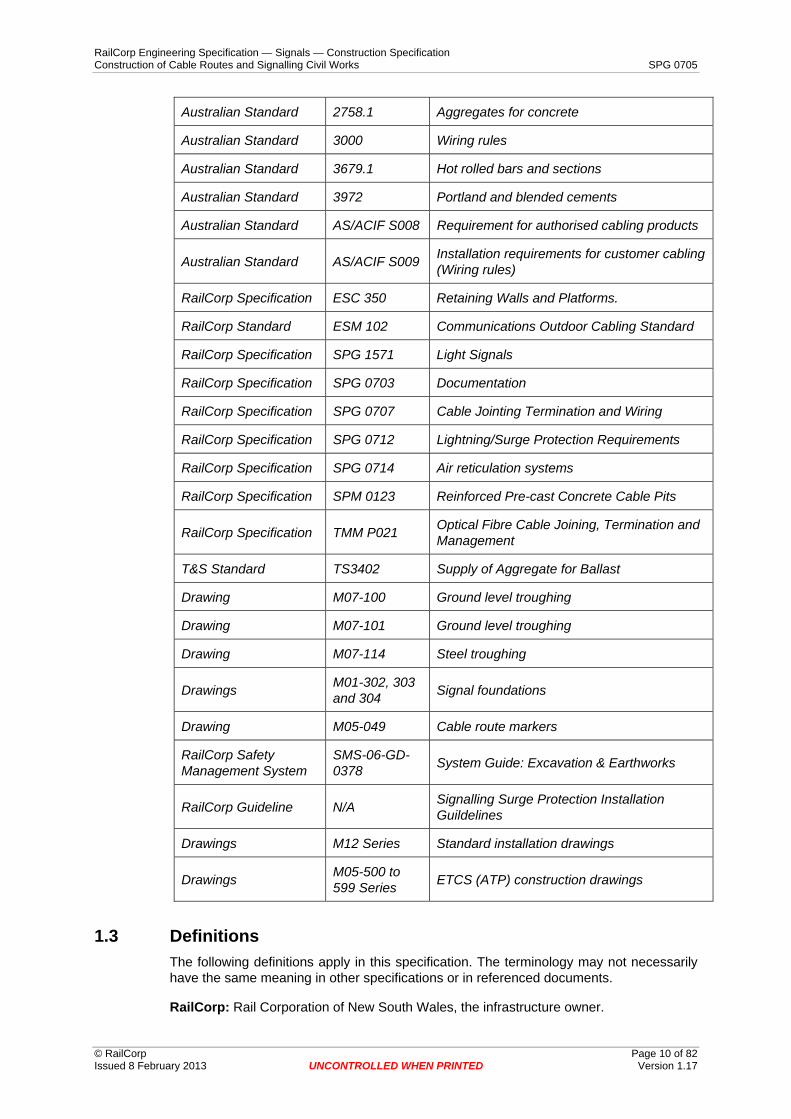
1.2 Referenced Documents The following documents and drawings are referenced in this specification:-
Methods of Testing Soils for Engineering Australian Standard 1289 Purposes
Australian Standard 1379 Manufacture of concrete
Australian Standard 1650 Hot dipped galvanised coatings
Australian Standard 1657 Fixed platforms, walkways, ladders, stairways
Conduits and fittings for electrical Australian Standard 2053.1 Installations – General Requirements
RailCorp Engineering Specification — Signals — Construction Specification Construction of Cable Routes and Signalling Civil Works SPG 0705
© RailCorp Page 10 of 82 Issued 8 February 2013 UNCONTROLLED WHEN PRINTED Version 1.17
Australian Standard 2758.1 Aggregates for concrete
Australian Standard 3000 Wiring rules
Australian Standard 3679.1 Hot rolled bars and sections
Australian Standard 3972 Portland and blended cements
Australian Standard AS/ACIF S008 Requirement for authorised cabling products
Australian Standard AS/ACIF S009 Installation requirements for customer cabling (Wiring rules)
RailCorp Specification ESC 350 Retaining Walls and Platforms.
RailCorp Standard ESM 102 Communications Outdoor Cabling Standard
RailCorp Specification SPG 1571 Light Signals
RailCorp Specification SPG 0703 Documentation
RailCorp Specification SPG 0707 Cable Jointing Termination and Wiring
RailCorp Specification SPG 0712 Lightning/Surge Protection Requirements
RailCorp Specification SPG 0714 Air reticulation systems
RailCorp Specification SPM 0123 Reinforced Pre-cast Concrete Cable Pits
RailCorp Specification TMM P021 Optical Fibre Cable Joining, Termination and Management
T&S Standard TS3402 Supply of Aggregate for Ballast
Drawing M07-100 Ground level troughing
Drawing M07-101 Ground level troughing
Drawing M07-114 Steel troughing
Drawings M01-302, 303 and 304 Signal foundations
Drawing M05-049 Cable route markers
RailCorp Safety Management System
SMS-06-GD-0378 System Guide: Excavation & Earthworks
RailCorp Guideline N/A Signalling Surge Protection Installation Guildelines
Drawings M12 Series Standard installation drawings
Drawings M05-500 to 599 Series ETCS (ATP) construction drawings
1.3 Definitions The following definitions apply in this specification. The terminology may not necessarily have the same meaning in other specifications or in referenced documents.
RailCorp: Rail Corporation of New South Wales, the infrastructure owner.
RailCorp Engineering Specification — Signals — Construction Specification Construction of Cable Routes and Signalling Civil Works SPG 0705
© RailCorp Page 11 of 82 Issued 8 February 2013 UNCONTROLLED WHEN PRINTED Version 1.17
Access Road: An access road is any track or roadway within the railway easement other than the defined entrance/exit roadway to a station, goods yard or compound or easement for access to property owned by others.
Backfill: Backfill is compactable material free of rocks that will not pass through a 50mm sieve and free of broken concrete, brick, rubble, wood, glass, rubbish, steel or other metal objects that could damage cables or affect the operation of electronic cable locators.
Ballast: Ballast is material in accordance with Way and Works Technical Standard TS3402 titled ‘Specification for Supply of Aggregate for Ballast’.
Cable plowing: Cable plowing is the process of installing cable and its protective system using a cable box attached to the tyne of a tractor.
Cable route: Cable route means any material installed or excavation carried out for the installation of cables between two points.
Clean fill: Clean fill is sand (or soil) that is free of stones, rocks, wood, metal and rubbish.
Communications cable: Communications cable is all main and local communications cables including communication cables to station buildings, relay rooms, location cases, trackside telephones, etc.
Contractor: The company, corporation, authority or person contracted to carry out the work covered by this specification.
Cover strip: The cover strip is the strip (or layer) of recycled plastic protective material placed over buried cables.
External cable route: External cable route is any cable route not in a building.
GLT: Ground level troughing (refer to Section 7.1)
GST Galvanised Steel Troughing (refer to Section 8)
High voltage: For the purposes of this specification only high voltage is any voltage greater than 120 volts (nominal).
Internal cable route: Internal cable route means any cable route inside a building.
Location case: (also called location cupboards or locations) Location cases are signalling equipment cupboards or housings that are not buildings.
Local cable route: (also called local route) Local cable route is any cable route, which does not fall into the category of main or internal cable route.
Local Cables: Local cables are all cables not being main cables.
Low voltage: For the purposes of this specification low voltage is 120 volts (nominal) or less.
Main cable route: (also called main route) Main cable route means any external cable route, which contains or is intended to contain at least one main cable.
Main cables: Main cables are any cables, which are run from a cable termination point in one building, equipment room or location case to a cable termination point in another building, equipment room or location case. Note that joints in cables including those for loading and balancing purposes do not constitute a termination of the cable for the purposes of defining main cables.

RailCorp Engineering Specification — Signals — Construction Specification Construction of Cable Routes and Signalling Civil Works SPG 0705
© RailCorp Page 12 of 82 Issued 8 February 2013 UNCONTROLLED WHEN PRINTED Version 1.17
Signalling cables: Signalling cables means but is not limited to cables to signals, points, trainstops, ground frames, releasing switches, level crossings, buffer stop lights, guards indicators etc. plus cables between equipment rooms and between equipment rooms and location cases.
Stabilised sand: Stabilised sand is a mixture of sand and portland cement in the ratio 10:1.
Structures: Structures are overbridges or underbridges, road, rail or pedestrian bridges, overhead wire supports, retaining walls, parapet walls and platforms.
Track circuit cables: Track circuit cables include but are not limited to cables from the equipment room or location case to the bootleg riser or to the trackside equipment boxes in the case of the Jeumont Schneider HV impulse and the audio frequency track circuits plus cables from the Jeumont Schneider and the audio frequency track circuit trackside equipment to the track.
Track Plan: (also called Signalling Plan) The plan showing general signalling arrangements.
ULX: Under Line Crossing (refer to Section 5.5)
URX: Under Road Crossing (refer to Section 5.5)
1.4 Approvals and Inspections Where this specification states that a product, process or installed work requires inspection or submission for review, consideration acceptance or approval before further work is to be carried out, such inspection or submission shall be arranged through the Regional Representative. Similarly where this specification states that a location, or action to be carried out, is “nominated” or “as directed” or is “authorised”, such nomination, direction or authorisation shall be obtained from the Regional Representative.
1.5 Environmental Considerations All cable route shall be designed to be as unobtrusive as possible, both to reduce its visual impact on its surroundings and to avoid drawing attention to the presence of copper cable.
The route shall not be attached to or alter the appearance of any building or structure, which is on a heritage list or is subject to a preservation order without specific approval from the relevant heritage authorities.
Trees or shrubs shall only be removed or lopped to the least extent necessary for construction of the route. Care shall be taken not to damage the root systems of mature or substantial trees.
During the construction of trenching for buried cable route or ground level ducting, care shall be taken to prevent silt runoff into any waterway and to prevent blockage of any natural or track drainage.
1.6 Responsibilities Unless otherwise specifically stated herein or in the Particular Specification, all work and actions specified or implied in this Specification and the supply of all material and plant necessary to carry out the work shall be the responsibility of the Contractor.

RailCorp Engineering Specification — Signals — Construction Specification Construction of Cable Routes and Signalling Civil Works SPG 0705
1.7 Site Surveys
© RailCorp Page 13 of 82 Issued 8 February 2013 UNCONTROLLED WHEN PRINTED Version 1.17
Detailed site surveys shall be carried out to determine locations for external work including equipment, structures, buildings, equipment housings, track circuit limits, foundations, cable routes, under-track crossings and all like work. Detailed site survey drawings, installation drawings and notes etc. shall be prepared and submitted for acceptance at least 14 days prior to work commencing.
Site works shall be executed in accordance with the accepted detailed site survey drawings, installation drawings and notes etc. that have been accepted.
1.8 Location of Equipment No equipment shall be located within the Standard Structure Gauge envelope as shown on Drawing Nos. 112000/1/1 and 112000/1/2. If site constraints are such that the equipment cannot be installed without infringement of this envelope, details of the required infringement shall be referred for specific approval.
1.9 Signal Location During the detailed site survey, the actual positions for the installation of signals in accordance with the requirements laid down in the relevant sections of Specification SPG 0706 “Installation of Trackside Equipment”, shall be established.
Each signal shall be positioned in relation to rail level, the structure gauge and shall be given a kilometrage or a distance from a well defined structure such as a bridge, platform, gantry or overhead wiring structure.
The distance from the running face of the nearest rail to the centre of a signal of standard width shall normally be between 2.1 and 2.3 metres. Where signals cannot be located adjacent to the track in the correct position due to the closeness of adjacent tracks or some other obstruction, the requirements of Specification SPG 0706 shall apply.
When the positions for signals, indicator signals, guards indicators etc., has been determined, master copies of signal sighting forms with full details and information, duly completed to the RailCorp's current practice specified in Appendix B, shall be forwarded to the Regional Representative.
The Contractor, in conjunction with the Regional Representative and representatives of train operators and signalling system designers (whether Contractor’s staff or others), shall then carry out a survey of the site to confirm all signal positions. Signal sighting forms with signatures of all parties shall then be used for the execution of the Works.
1.10 Installation Drawings This Standard Specification includes, or references, a number of standard installation drawings illustrating guidelines for the construction of cable route and the installation of trackside equipment. The arrangements shown in the Standard Installation Drawings (M12 series) shall be used. Where standard installation drawings are not supplied or where particular problems are encountered on site that require special arrangements or equipment to complete the work, the necessary construction/installation drawings shall be prepared and submitted for approval prior to the work being started.
Drawings that may require preparation shall include, but are not limited to:
a) Impedance bond mounting frames
b) Signal installation including base, ATP pit, ladder base and conduits
RailCorp Engineering Specification — Signals — Construction Specification Construction of Cable Routes and Signalling Civil Works SPG 0705
© RailCorp Page 14 of 82 Issued 8 February 2013 UNCONTROLLED WHEN PRINTED Version 1.17
c) Illuminated trackside signs
d) GST brackets for attachment to rock faces
e) GST posts on masonry walls
f) Track circuit trackside unit mounting posts
g) Pit details including lids, floors and ladders
h) Cabling arrangements and attachments for AF track circuits
i) Locations on elevated platforms
j) Locations on concrete plinths
k) Galvanised pipe cable route on platform coping walls
l) Releasing switch assembly including base
m) Releasing switch name plate brackets and name plates
n) Power supply kiosk foundation, conduits and fixing arrangements
o) GST jointing bay
p) GST/ULX Interface
q) Cable routes on gantries
r) Electrolysis bond choke installation arrangements
s) Guards indicator posts and cable arrangements
t) Warning light mounting and cable arrangements
u) Telephone on post and mounting base
v) Retaining walls
w) Access ways to locations on embankments
1.11 Existing Equipment Where existing signalling or communications equipment that is ultimately to be removed or recovered under the provisions of Section 25 inhibits the installation of new signalling or communications equipment, the Regional Representative will determine the action to be taken. The Contractor may be directed to:
a) Carry out temporary work.
b) Re-position the new equipment.
If the former alternative is adopted the Contractor is not thereby relieved of his responsibility for fully carrying out the provisions of Section 25.
1.12 Temporary Level Crossings Temporary level crossings shall not be constructed without prior written approval. If approved, temporary level crossings shall comply with RailCorp’s procedures for construction, level of protection and operation of temporary level crossings.

RailCorp Engineering Specification — Signals — Construction Specification Construction of Cable Routes and Signalling Civil Works SPG 0705
© RailCorp Page 15 of 82 Issued 8 February 2013 UNCONTROLLED WHEN PRINTED Version 1.17
The Contractor shall be responsible for the cost of construction of the temporary level crossings, and for their maintenance and operation including the provision of protection as required.
At the completion of the work these level crossings shall be removed and the track restored to a condition at least equal to that of the track on either side of the crossing.
1.13 Location of Services The renewal area is likely to contain numerous existing buried services not all of that are fully documented. The location of all services within a one metre distance of any proposed installation work shall be determined prior to commencing the work.
Services searches & excavation & earthworks are to comply with SMS-06-GD-0378 – System Guide: Excavation & Earthworks”.
1.14 Alternative Materials, Products or Processes Where this specification proposes a particular material, product or process or range of materials, products or processes, alternatives may be accepted for use where permitted by the Particular Specification, provided that they receive Type Approval and it can be demonstrated that the alternative:
a) Is fit for purpose
b) Is better rather than worse in optimally achieving the performance requirements.
c) Improves rather than reduces system safety, security and availability.
d) Is closer rather than further from best practice.
e) Is equally or more suitable in form, fit and function, and equally or more compatible with it’s interfaces, operating environment and maintenance environment.
f) Increases rather than decreases compliance with environmental and occupational health and safety requirements.
g) Decreases rather than increases life cycle costs.
h) Improves rather than reduces maintainability and supportability
i) Increases rather than decreases adaptability for foreseeable change.
j) Provides a net benefit to RailCorp.
2 Supply Of Materials
2.1 Material Supplied by the Regional Representative If it is agreed that the Regional Representative will supply cables or other materials for the works, either in full or part, the material will be made available at an agreed location (or locations) for collection.
After collection responsibility for the safe storage and handling of such equipment or materials, effective and efficient use of the quantities supplied and maintenance of quality records (including serial numbers, reference numbers etc) and installation records rests solely with the Contractor.
RailCorp Engineering Specification — Signals — Construction Specification Construction of Cable Routes and Signalling Civil Works SPG 0705
© RailCorp Page 16 of 82 Issued 8 February 2013 UNCONTROLLED WHEN PRINTED Version 1.17
Accurate records shall be maintained on the cables or other materials supplied, the quantities installed and the locations where they have been installed. A copy of these records shall be available to the Regional Representative on demand and when requests are submitted for further supplies of cables or other materials.
Unused cables and other materials shall be delivered, unloaded and stockpiled at a nominated site after the completion of the installation work.
Empty cable drums shall be delivered, unloaded and stockpiled a nominated site within a 20km radius of the worksite.
2.2 Materials Supplied by the Contractor All materials and equipment used in the works shall be covered by the quality and test and inspection documentation required by specification SPG 0711.
In particular, cable drums are supplied with drum numbers marked on the drum and the cable manufacturer's factory test results sheets. The cables shall not be installed until the factory test results have been sighted and approved.
Cable drums with illegible or no drum numbers shall be rejected. Any drums missing manufacturer's test data sheets shall not be used.
2.3 Painting/Finish of Metal Surfaces All steel components or constructions shall be proofed against corrosion by a process, which will provide a minimum service life of 30 years in the environment in which the components or constructions are installed.
In selecting the process to be used, the likelihood of minor damage during installation such as scrapping, scratching and chipping shall be taken into account.
Painted or powder coated finishes are not acceptable as the primary corrosion proofing process in external applications, but may be used to provide additional protection in those instances or locations where the primary process cannot provide the specified service life.
Fasteners used externally to buildings shall be either plated or of a material that will provide the specified life. (Note: If stainless steel nuts are used on stainless steel fasteners, an anti-seize product shall be used between nut and bolt).
For applications within buildings, except in wet areas such as cable pits, the level of protection may be reduced to zinc plating or equivalent.
Painting of galvanised (or equivalently plated) steel, stainless steel and aluminium metalwork is not necessary except where required for additional protection or where it is called for in the Particular Specification.
Where a paint finish is specified, powder coating, enamel, epoxy coatings or acrylic lacquer finishes may be used. The metal shall be surface cleaned, etched, primed, undercoated and finished in accordance with the paint manufacturers' recommendations.
Finish colour of painted surfaces shall be compatible with the environment in which they are located.
RailCorp Engineering Specification — Signals — Construction Specification Construction of Cable Routes and Signalling Civil Works SPG 0705
3 Excavation, Boring, Backfilling And Compaction
© RailCorp Page 17 of 82 Issued 8 February 2013 UNCONTROLLED WHEN PRINTED Version 1.17
3.1 Excavation
3.1.1 Location of Existing Services Before excavation or boring operations commence, the location of all existing signalling and communications cables, railway drains and all other underground services in the area to be excavated including water, stormwater, sewerage, gas, power and telephone cables shall be located and marked. The use of mechanical digging or boring machines for excavation within 2 metres of high voltage cables or within 1 metre of other existing underground service is not permitted. Excavation within 2 metres of high voltage cables or within 1 metre of other existing underground services shall be performed using hand tools.
Explosives shall not be used in the performance of the work under the Contract.
The search for services shall be carried out in accordance with RailCorp’s Services Search procedures.
3.1.2 Preparation of Cable Route The selected cable route shall be cleared and levelled only to the extent necessary to permit trenching and access for plant/vehicles. Any debris, excess soil and/or rock shall be disposed to a rubbish tip or other approved location. Any railway materials (eg sleepers) in the cable route path shall be relocated to nominated locations.
Care shall be taken to ensure that this work does not block natural drains or create un-drained areas.
Excavations shall be to the minimum width and depth necessary to best carry out the work in accordance with this specification. The bottom of trenches shall be level and even, free from stones, sharp objects etc.
3.1.3 Stability of Excavation Excavations in or near tracks, platforms or access roads shall be securely shored to prevent the sides of the excavation from collapsing. All trenches shall be shored to comply with the requirements of the Construction Safety Act.
Excavation work shall not commence in or near tracks, platforms or access roads until sufficient shoring material is available on site to shore up the excavations as the work progresses.
3.1.4 Placement of Spoil Spoil shall not be placed on ballast or foul of track gauge or access-ways. If spoil has to be temporarily placed on the track, tarpaulins, plywood or other suitable material shall be used to provide a barrier between the ballast and the spoil.
Spoil placed between the rails or within 1000mm from any rail shall not extend above the top of rail level.
Spoil shall not be placed in a position where it could obstruct track drainage or be washed into track drains or onto the ballast during periods of heavy rain.

RailCorp Engineering Specification — Signals — Construction Specification Construction of Cable Routes and Signalling Civil Works SPG 0705
© RailCorp Page 18 of 82 Issued 8 February 2013 UNCONTROLLED WHEN PRINTED Version 1.17
Spoil shall not be placed in a position where it may damage or affect the operation of existing equipment (eg. mechanical signalling control rodding or wires, cable routes, power operated points, trainstops etc.).
Driver’s safe and unrestricted access to signal telephones shall be maintained at all times.
3.1.5 Programming of work As far as possible trenching, cable laying and backfilling shall be carried out progressively and concurrently so that trenches are open for the minimum possible time. Work shall be planned such that trenches are required to be kept open for a maximum of five working days except for:
a) trenches under or within 3 metres of operating tracks, or
b) where the stability of the embankment and or formation is affected, or
c) through sidings
where the trench shall not be kept open overnight unless it is shored to prevent any movement of surrounding ground under any weather conditions.
3.1.6 Public Safety To ensure the safety of the Public, suitable barricades shall be erected around excavations, or covers across excavations where continuous access is required across them, when work is not actually taking place. Barricades shall have a minimum height of 1000mm and barricades and covers shall comply with the Occupational Health and Safety Act.
Excavation on platforms shall cause the minimum interference and risk to the public and train operations. Temporary covers shall be provided for trenches to allow access to trains, platform amenities and booking offices. At no time while train services are running shall access to or from the platform to any part of a train be blocked.
Excavated material shall not be stockpiled on platforms unless agreement is reached with the station owner, RailCorp.
3.1.7 Proximity to Existing Services When trenching alongside or across gas, water mains or service utility lines the Contractor shall comply with any restrictions that may apply to the easement and liaise with the owners of that easement to establish mutually agreed methods of protection and support for the services.
When excavation or trenching must be carried out adjacent to existing services (i.e. cables, wiring, gas or water pipes), the service, if within 500mm of the excavation, shall be carefully exposed and protected with 12mm steel plate.
On completion of the work the service shall be jointly inspected by the Regional Representative, service owner and the Contractor to ensure that no damage has occurred and the service is operating correctly.
3.2 Inspection before Backfilling Trenches and other excavations shall not be backfilled until inspected.

RailCorp Engineering Specification — Signals — Construction Specification Construction of Cable Routes and Signalling Civil Works SPG 0705
3.3 Backfilling
© RailCorp Page 19 of 82 Issued 8 February 2013 UNCONTROLLED WHEN PRINTED Version 1.17
Pipes and cables shall be encased in clean fill to 50mm above the uppermost pipe or cable.
Whenever excavation of the track formation occurs, the formation shall be restored with compacted stabilised sand and the capping layer with compacted material to SPC411. Any geotechnical fabric encountered during excavation shall be replaced with like material, which overlaps the original by at least 300mm.
Ballast shall not be replaced until the trench or excavation has been filled and compacted level with the top of the capping layer.
Where the buried pipe or cable is located in areas other than track formation, platforms, access roads or pathways, the trench above the clean fill shall be filled with material free of broken concrete, brick, rubble, wood, glass, rubbish, steel or other metallic objects that could damage the cable or effect the operation of a electronic cable locators and shall be free of stones that will not pass through a 50mm sieve.
The top 150mm at least of fill in access roads or pathways, which are not sealed, shall consist of material, which as closely as possible matches that in the road or pathway surface in both texture and density. The fill shall be compacted as necessary to achieve matching density. Where the road or path is sealed, the trench shall be capped with the same material to the same thickness as the original seal. Any substrate or capping layer below the seal shall also be matched.
Surface drains shall be reinstated during the backfilling operations.
The backfilling of the excavations will normally take up the majority of the spoil. However, any surplus spoil or unsuitable fill shall be removed for disposal at an appropriate location.
Prior to the issue of the Certificate of Practical Completion, all backfilled trenches and excavations shall be examined and any depressions caused by settlement or erosion of the backfilling shall be corrected and the cause of the erosion rectified.
3.4 Compaction The first 150mm of fill over cover strips or pipes shall be carefully compacted to ensure that the cover strips / pipes are not disturbed.
Trenches and other excavations in the track formation, platforms, roads, pathways, through shunting yards or at the base of embankments shall be:
a) Compacted by mechanical means to achieve 95% Standard Compaction in accordance with AS1289, and
b) Filled and compacted in layers of 150mm maximum thickness to achieve the specified density.
Tests shall be performed to establish the backfill compaction levels achieved. The tests shall be taken on a frequency of one (1) test per 200 linear metres per layer or one (1) test per area per layer where any area of excavation is less than 200 metres long. Audit testing of soil compaction at all levels may be carried out by the Regional Representative and due allowance for any interference caused by this testing shall be made.
Where backfill does not achieve the required density, it shall be re-excavated to within 200mm of the cover strips and/or pipes and re-filled and compacted correctly.

RailCorp Engineering Specification — Signals — Construction Specification Construction of Cable Routes and Signalling Civil Works SPG 0705
© RailCorp Page 20 of 82 Issued 8 February 2013 UNCONTROLLED WHEN PRINTED Version 1.17
Trenches and excavations in other areas, not specified above, may be compacted by any convenient means, e.g. by using the wheels of a backhoe or bobcat. Following compaction, the trench or excavation shall be finished with a slight mound, height equal to approximately 20% of trench width, to provide for further settlement.
Where an ULX has been made and the sleepers have not been removed, in addition to the above the following shall apply:
a) The ballast shall be compacted with a whacker packer in layers of 150mm.
b) Where it is difficult to use the whacker packer under the sleepers, as minimum, make sure that the ballast is restored under the sleepers and tamp the ballast under the sleeper with a vibrating tamping head (eg hand-held Cobra tamper).
c) Compact the crib area thoroughly between the sleepers.
d) It may not be possible to compact the ballast shoulders that are outside of the sleepers.
4 Concrete And Stabilised Sand
4.1 General This section of the Standard Specification details the requirements for the supply of:
a) concrete for the construction of foundations, footpaths, cable pits and other concrete structures of a minor nature.
b) stabilised sand.
Except when otherwise approved, ready mixed concrete shall be used in the construction of all concrete structures.
4.2 Ready Mix Concrete and Stabilised Sand Ready mixed concrete and stabilised sand shall be produced in accordance with the requirements of AS1379. The Contractor shall be responsible for ensuring that concrete and stabilised sand is ordered with the correct properties for its intended application.
Concrete strength at 28 days shall be not less than 20 MPa.
Concrete additives shall not be used without approval.
4.3 Site Mixed Concrete and Stabilised Sand The materials for site mixed concrete and stabilised sand shall be kept free of foreign matter at all times.
Concrete mix portions by volume shall be as necessary to obtain the necessary strength for the particular application with a minimum strength of 20 Mpa for any application.
Portland cement type A to AS3972 shall be used unless otherwise specified and aggregate shall comply with AS2758.1.
Mixing water shall be clean and free from substances deleterious to concrete or steel.
Chemical admixtures or fly ash shall not be used in the concrete mix.
RailCorp Engineering Specification — Signals — Construction Specification Construction of Cable Routes and Signalling Civil Works SPG 0705
4.4 Concrete Reinforcing
© RailCorp Page 21 of 82 Issued 8 February 2013 UNCONTROLLED WHEN PRINTED Version 1.17
All concrete structures and pathways shall be appropriately reinforced with welded rust free steel mesh to AS 1304 and/or steel bar to AS 1302 of sufficient cross-sectional area for the calculated loadings.
Reinforcement shall be placed and tied (and/or welded) in accordance with the design drawings.
4.5 Concrete Finish Internal concrete surfaces shall be free of voids and steel trowelled to a smooth finish. External concrete surfaces shall be finished to a non-slip wood trowelled finish.
Concrete edges and corners shall be chamfered to minimise chipping and breaking.
Concrete surfaces shall be level except where a slope is required to form a ramp or to disperse water away from a building or other structure.
5 Cable Route General Requirements
5.1 General The setting out and the construction of the cable route shall be in accordance with the provisions of this specification. As a minimum, cable installation must comply with RailCorp standard ESM 102 and both AS/ACIF S009 and AS 3000. The requirements detailed in this specification typically meet or exceed the requirements in the nominated standards.
Except as otherwise specified, the main cable route shall be installed on one side of the track (except where there are four tracks or more, in which case the route may be split to run down each side when convenient) and shall cross the track the least possible number of times. Local cable routes shall be installed as required.
Cable route shall, so far as possible, follow a constant grade and line. Rough and uneven ground shall be levelled to the extent necessary to achieve this object. Where buried route is installed, only sufficient surface levelling to provide access shall be carried out. Levelling work shall not adversely affect railway or natural drainage, or pedestrian or vehicular access routes.
5.2 Location of the Cable Route Generally the cable route shall be located as near as possible to the railway boundary. The preferred locations for cable routes are shown on Drawing Nos. 112000/5/1, 112000/5/2 and 112000/5/3.
The minimum distance from the running face of the nearest rail to the cable route shall be not less than four (4) metres without written approval.
Cable routes shall be parallel to the running lines wherever possible.
The cable route shall be located and installed so that it does not divert or interfere with any drainage (railway or natural) or underground services. Special care shall be taken to ensure that the route will not affect the stability of any embankment or cutting.
Where large waterways, gullies or roadways under tracks are encountered the cable route may be fixed to available bridge structure using approved attachments as set out in Section 8.8.

RailCorp Engineering Specification — Signals — Construction Specification Construction of Cable Routes and Signalling Civil Works SPG 0705
© RailCorp Page 22 of 82 Issued 8 February 2013 UNCONTROLLED WHEN PRINTED Version 1.17
For small creeks and occasional waterways the cables shall be enclosed in pipes laid in trenches under the creek bed as set out in Section 6.16.
Cable routes shall, where possible, be on the side of the tracks not occupied by high voltage earthed locations such as sub-stations, power sectioning huts and transformer locations.
Cable routes under roadways shall be installed within the railway corridor whenever possible.
Where the cable route cannot be located within the railway corridor, all negotiations with the owners of land affected by the proposal or with Local or Public Authorities shall be carried out by the Contractor and a specific proposal submitted.
In such instances the detailed site survey drawing shall show the land owner's name and the deposited plan and folio numbers pertaining to the land.
Agreement in writing shall also be obtained from the land owner permitting RailCorp access in future years for cable renewal/repair. Any special conditions of entry shall be noted in this document. The original of this document shall be given to the Regional Representative who will retain a copy and forward the original to RailCorp’s Asset Manager for the area concerned.
5.3 Types of Cable Route a) Cable Route Types are
Type 1 Cable (excluding communications cable) buried directly in the ground - Drawing No. 112000/5/4.
Type 2 Cable (excluding communications cable) buried directly in the ground with one spare pipe buried over the cable to be accessed in future if required - Drawing No. 112000/5/4.
Type 3 Cable (excluding communications cable) buried directly in the ground with one or more pipes buried over the cable and pits at regular intervals - Drawing No. 112000/5/4.
Type 4 Cable buried in pipes with pits at regular intervals - Drawing No. 112000/5/5.
Type 5 Ground Level Troughing (GLT), heavy wall type concrete
Alternatively “RAILDUCT 2000” HDPE or equivalent ducting for areas where vehicles do not have access.
Type 6 Galvanised Steel Troughing on posts or brackets (GST)
Type 7 Galvanised Steel Ladder on Wall
Type 8 Aluminium Ladder on Wall
Type 9 Stainless Steel Ladder on Wall
Types 3 to 9 inclusive are classed as “re-enterable” cable route.
Requirements for cable routes are specified in:
Types 1, 2, 3 and 4 Section 6

RailCorp Engineering Specification — Signals — Construction Specification Construction of Cable Routes and Signalling Civil Works SPG 0705
© RailCorp Page 23 of 82 Issued 8 February 2013 UNCONTROLLED WHEN PRINTED Version 1.17
Type 5 Section 7
Type 6 Section 8
Type 7, 8 and 9 Section 9
Where cables are buried through platforms cable route Type 4 shall be used.
5.4 Radius of Bends The smallest radius bend in any cable route shall not be less than the manufacturers recommended minimum radius for the largest cable to be installed in that route.
5.5 Underline Crossings (ULX) and Under Road Crossings (URX) Underline and under-road crossings shall be provided in accordance with the provisions of Section 11.
5.6 Cable Pits Cable pits, cable jointing pits and cable turning chambers shall be provided in accordance with the provisions of Section 11.
6 Buried Cable Route (Cable Route Types 1,2,3 and 4)
6.1 General The excavation of trenches, backfilling and compaction shall be carried out in accordance with the requirements of Section 3.
To avoid the need to re-open cable trenches, main and local cables shall be installed in buried cable areas at the same time.
Airlines may be included in the trench alongside the cables as set out in the Air Reticulation Standard Specification SPG 0714.
6.2 Depth of Cable Route Cables and pipe buried in ground shall have a minimum cover of 800mm from the cover strip or topmost pipe to ground level.
The top of cables and pipe buried in the track formation shall be a minimum of 1600mm below rail level.
Where cables are to be installed in ULX and URX pipes the provisions of Sub-Section 11.2 shall apply.
6.3 Shared Trenches Where communications and signalling cables are installed in the same trench (possibly with power and / or other services also), then:
a) Conduits shall be grouped in accordance with the diagrams below, with horizontal separation between signalling conduits, communications conduits and conduits for other services. (Vertical separation of high voltage power

RailCorp Engineering Specification — Signals — Construction Specification Construction of Cable Routes and Signalling Civil Works SPG 0705
conduits from other services is allowable.) Signalling air mains shall be included in the signalling conduit group.
b) The minimum separation between communications cables and High Voltage power cables shall be the greater of the separation specified in RailCorp standard ESM 102 and as specified in Standards Australia / Australian Communications Industry Forum AS/ACIF S009. The minimum separation between communications cables and signalling or other power cables shall be as specified in AS/ACIF S009.
c) Where practical, the signalling cable group shall be located on the side nearest the running rails, to facilitate the installation of tail cables to trackside equipment.
d) Communications conduits shall be coloured white; signalling and power conduits shall be orange. (If air mains are run in a separate conduit that may be coloured blue, or else the same colour as other signalling conduits.) Conduits for other types of service should be appropriately coloured, generally in accordance with AS1345
Marking Tapes to be located 300mm below ground level directly over the appropriate conduits
800 minimum
RailCorp Signalling Conduits (Orange)
High Voltage Conduits (Orange)
RailCorp Communications Conduits (white)
As a general rule, signalling conduits shall be closest to the track where they require frequent access to the track
Ground level
450 minimum (see also ESM 102)
Figure 1 - Arrangement of Conduits in Shared Services Route – Sharing with vertically separated HV power conduits
© RailCorp Page 24 of 82 Issued 8 February 2013 UNCONTROLLED WHEN PRINTED Version 1.17

RailCorp Engineering Specification — Signals — Construction Specification Construction of Cable Routes and Signalling Civil Works SPG 0705
As a general rule, signalling conduits shall be closest to the track where they require frequent access to the track
Ground level
300 Minimum Depth of cover, protection and marking tapes as required by Electrical Design
Note: Communications and Signalling conduits may be reversed, but the separation between HV conduitsand the Communications conduits shall be 450mm or as per RailCorp standard ESM 102
Marking Tapes to be located 300mmbelow ground level directly over the appropriate conduits
800 minimum.
RailCorp Signalling Conduits (orange) High Voltage
Conduits (orange)
RailCorp Communications Conduits (white)
Figure 2 - Arrangement of Conduits in Shared Services Route – Sharing with horizontally separated HV power conduits
6.4 Protective Cover over Signalling and Communications Cables To provide mechanical protection to signalling, communications and power cables the Contractor shall provide a separate cover strip covering all the cables (minimum cover width of 150 mm). The cover strip shall be placed on top of the cables and overlap the cables by not less than 50 mm on each side as shown on Drawing No. 112000/5/4.
6.5 Earth Cables and Wires in Trenches Bare copper earth cables shall be installed in cable trenches in areas, which are proposed for 25KV AC electrification. Stainless steel earth wires shall be installed in cable trenches in all other areas. At a distance midway between location cases or buildings a 10 metre long gap is to be provided between the ends of the earth wires.
Earth wires in trenches shall not be located within 20 metres of any high voltage earth installation.
The Particular Specification will indicate whether or not the area concerned is proposed for 25KV AC electrification and the earthing arrangements shall be installed in accordance with the requirements of Standard Specification SPG 0712.
In the non-electrified area only, a 2.0mm diameter grade 316 stainless steel shielding earth wire is used as a grading wire to protect the cables in a direct-buried cable route from damage due to lightning. Alternatively, 0.5mm thick, 6mm wide tape of grade 316 stainless steel may be used.
The stainless steel earth wire, when installed for a direct buried cable route must be:
• Run a minimum of 300mm above the top cable and 300mm below the surface.
© RailCorp Page 25 of 82 Issued 8 February 2013 UNCONTROLLED WHEN PRINTED Version 1.17
RailCorp Engineering Specification — Signals — Construction Specification Construction of Cable Routes and Signalling Civil Works SPG 0705
© RailCorp Page 26 of 82 Issued 8 February 2013 UNCONTROLLED WHEN PRINTED Version 1.17
• Terminated on the location main earth bar to allow for disconnection when testing the location earth.
• Insulated until it has passed the location earth mat by more than 1 metre so that it does not influence the location earth when disconnected for location earth testing.
• Have individual pieces of wire jointed using a stainless steel U clamp or welded connection.
• Broken at the mid-point between locations to prevent the transfer of earth-potential rises between locations. The break must be at least 4 metres. The ends do not need to be terminated on earth stakes as per previous practice.
• Broken for 20 metres either side of high voltage earths to prevent fault current being collected and directed along the signalling High voltage cable to the signalling location. High voltage earths are the earths found at 11KV or higher power poles and AC substations.
• If the cable route is run alongside a high voltage pole line with an overhead earth wire, then the stainless steel wire is not to be installed.
6.6 PVC Cable Marker Tape in Trenches WAY SIGNALLING CABLES" marker 150mm wide orange coloured PVC "DANGER RAIL
tape shall be installed in all trenches 300 mm below ground level as shown on Drawing Nos. 112000/5/4 and 5 except where cables are permitted in shallow trenches due to rock, etc. when the depth of the marker tape shall be not less than 100mm above the protective cover.
6.7 Rock Areas In rock areas, the cables shall be laid on a bed of sand 100mm thick. (Drawing No. 112000/5/6)
The depth of cables in rock and shale areas shall normally be at least 600mm to cover strip or pipe except that in areas of unbroken rock a reduction in depth to 300mm may be permitted.
The final 150mm of fill of trenches in rock areas shall be stabilised sand, or concrete if in vehicle access roads.
6.8 Cable and Pipe Plowing - Preparation of Route The cable route shall be prepared to permit the continuous plowing of each drum of cable and pipe. Cable route preparation shall include:
a) Grading and benching of the route as required to enable the cable and pipe to be buried at a constant depth.
b) Drilling and blasting (where permitted) of rock to enable the ground to be ripped.
The cable route shall be pre-ripped prior to the cable being plowed. Sufficient ripping passes shall be carried out, to a depth of at least 150mm below the required cable route, to provide a suitable bed of fines irrespective of type of ground.
If the required depth has not been ripped after six (6) passes, cross ripping shall be carried out to ascertain a possible alternative agreed location for the cable.
Multiple parallel ripping passes shall be carried out where there is an abrupt change in direction of the cable route of fifteen degrees (15°) or more.
RailCorp Engineering Specification — Signals — Construction Specification Construction of Cable Routes and Signalling Civil Works SPG 0705
6.9 Cable Plowing - General
© RailCorp Page 27 of 82 Issued 8 February 2013 UNCONTROLLED WHEN PRINTED Version 1.17
Cable shall be plowed by tractors using approved method(s), which will ensure that:-
a) The maximum load on the cables is less than 75% of the maximum tensile load recommended by the cable manufacturer. It is expected that the maximum tensile load of the optical fibre cable shall not exceed 1.3KN.
b) The cables or pipes are fed off the drums using mechanical means.
c) Immediate automatic detection protection against overstress of the cable is provided.
d) Where the cable or pipe undergoes a change in direction during the plowing operation, a roller or tray is provided to prevent damage to the cable and pipe.
e) The size of the roller/tray and feed tube is such that the radius bend in any cable is not less than the manufacturers recommended minimum radius bend for the largest cable being plowed.
f) The cable box is attached to the tyne and can be opened to enable the cable to be removed from the box without the cable being cut.
Cables and pipes shall be installed within a tolerance of ± 50 mm of the nominal depth subject to the minimum cover not being less than 800mm.
Communications cable shall be separated as required by RailCorp standard ESM 102 and AS/ACIF S009 and shall be above other cables.
Vibratory plowing, which uses vibrating motions as well as draw bar pull to bury cables, shall not be used.
Plowing of cables across sealed or unsealed public roads and sealed private roads is not permitted. Plowing across unsealed private roads may, however, be permitted with prior approval.
Plowing generally will not be permitted within 900 mm of any water, electrical or communications service or within 1500 mm of any gas service or other service carrying dangerous or flammable materials. In special circumstances permission may be granted to plow within these limits if it can be demonstrated that there is no possibility of damage to the service.
6.10 Cable Plowing - Demonstration To demonstrate ability to plow cables correctly, the Contractor shall plow cables over a 100 metre test section. These cables shall be installed in accordance with the Contractors proposed work methods.
Tests will be carried out on this section of cable route including:
a) A longitudinal stress test to determine that the cable has been laid without excessive stress.
b) Cable route preparation test to determine if the cable route has been adequately pre-ripped.
c) Cable position test to determine the accuracy of the location of the plowed cable and pipe.
RailCorp Engineering Specification — Signals — Construction Specification Construction of Cable Routes and Signalling Civil Works SPG 0705
© RailCorp Page 28 of 82 Issued 8 February 2013 UNCONTROLLED WHEN PRINTED Version 1.17
d) Testing to determine that no physical damage has occurred to the cable cores or insulation or to the pipe.
Results of the tests will be advised to the Contractor who shall amend ploughing methods to address all areas nominated as unsatisfactory.
6.11 Cable Plowing - Restoration Restoration work shall be carried out to restore the plowed route to as near as reasonably possible to its original state. Included in this work is ground stabilisation and cross drainage, where required, to reduce possible future soil erosion:-
Restoration work shall include:-
a) Removal of large rocks brought to the surface during plowing or ripping.
b) Nominal compaction of material left above ground by running a tractor track or rubber tyred vehicle (of similar weight) along the plow line.
c) Mechanical compaction of the top 300mm of the plowed trench in areas where scouring may occur along the main cable route or emergency off-road vehicle access is likely.
Leaving a small windrow along the cable route.
Minimum backblading to reduce erosion problems.
Grass seed distribution where of benefit in reducing erosion or restoring appearance.
6.12 Buried Pipes Pipes may be rigid UPVC, 'HD Coreflo' or HDPE jointed using the manufacturer's recommended jointing methods.
The wall thickness (or class) of pipe shall be sufficient to guarantee that there will be no loss of cross sectional area and that there will be less than 10% loss of diameter in any direction during or after backfilling, boring, plowing or pulling.
The minimum diameter of pipes shall be at least three (3) times the outside diameter of the cable to be pulled through the pipe with a minimum of 50mm diameter.
The number of pipes to be provided in ULX's, URX's and under access roads will depend on the cable route requirements in that area but provision shall be made for the following, as applicable.
a) Signalling and power cables shall be in separate pipes to communication cables.
b) High voltage cable shall be in a separate pipe to signalling or communications cable.
c) Each 2Kv, 11Kv or 33Kv cable shall be in a separate pipe
d) Unless otherwise approved, optical fibre cable shall be in a separate pipe.
e) Air lines shall be in a separate pipe.
Except for directionally bored ULX’s and URX’s pipes shall be laid parallel and level in a consistent format in the trench and secured in that position.

RailCorp Engineering Specification — Signals — Construction Specification Construction of Cable Routes and Signalling Civil Works SPG 0705
© RailCorp Page 29 of 82 Issued 8 February 2013 UNCONTROLLED WHEN PRINTED Version 1.17
Telecommunications cables shall be run in white conduits that comply with ACIF S008 Section 5.3 Outdoor Telecommunications Conduit/Pipe.
Signalling and electrical power cables shall be run in orange conduits that comply with AS2053.
Heavy-duty conduits shall be used when installed in trenches. Medium-duty conduit can be used for direct bore sections of cable routes.
6.13 Pipes in High Voltage Areas Where communications cables are required to be run into high voltage earthed locations such as sub-stations, power sectioning huts and transformer locations, these shall be looped into and out of the locations and be protected by pipes as shown on drawing No. NS 3286.
An 'earth mat' is provided around high voltage locations as part of the earth protection arrangements for the high voltage installations. All cables (signalling and communications) to be installed within 20 metres of the earth mat shall be run in pipes. Details of the extent of the earthing arrangements around each high voltage installation will be provided by the Regional Representative.
Existing high voltage earthing arrangements shall not be disturbed under any circumstances.
6.14 Spare Buried Pipes Spare pipes shall be provided as follows:
Cable Route Spare Pipes Type 2 One Type 3 Two or 20% of the number of pipes whichever is the greater* Type 4 One or 20% of the number of pipes whichever is the greater*
* In determining the number of spare pipes to be provided based upon the percentage of pipes, reference shall be made only to the resultant whole number and fractions shall be ignored.
All spare pipes shall be tested for correct diameter by pulling a plug of a diameter 90% of the internal pipe diameter through the pipe after installation, backfilling and compaction.
Where Type 2 or 3 route is specified the spare pipe(s) shall be laid over the cover strip as shown on Drawing No. 112000/5/4.
Where Type 4 route is specified the spare pipes shall be laid over the other pipes as shown on Drawing No. 112000/5/5.
Spare pipes shall be cleaned, fitted with a stainless steel draw wire suitably anchored at each end of the pipe and then sealed with proprietary end caps to prevent the ingress of dirt, etc
6.15 Pipes in Platforms and Other Paved Areas Pipes shall be arranged in fixed format for the full length of the platform or paved area and shall be supported so that backfilling will not disturb the format. The requirements of Section 3.3 shall apply.
RailCorp Engineering Specification — Signals — Construction Specification Construction of Cable Routes and Signalling Civil Works SPG 0705
© RailCorp Page 30 of 82 Issued 8 February 2013 UNCONTROLLED WHEN PRINTED Version 1.17
Where only pedestrian traffic is involved the depth of the pipes from the top of the trench to the top of the highest layer of pipes shall be not less than 300 mm.
Where motor vehicles can run over the surface the pipes shall be buried not less than 300 mm and a reinforced concrete slab, minimum150mm thick and overlapping the pipes by 300mm each side shall be provided immediately under the pavement surface material.
Cable pits for cable pulling purposes shall be provided in platforms in accordance with the requirements of Section 11.
6.16 Buried Cables through Water Courses For small creeks and occasional waterways the cables shall be enclosed in pipes laid in trenches not less than one meter under the creek bed. The pipes shall be covered to a minimum depth of 300mm with porous bags filled with stabilised sand and the remainder of the trench then filled to the top with heavy grade hardcore.
The pipes on creek banks shall be laid at a gentle slope in grooves in the banks so that the pipes have a minimum cover of 800 mm. The pipes in the banks shall be secured in position with suitable anchors and covered with porous bags filled with stabilised sand and topped with other suitable fill to protect the pipes and prevent erosion of the banks. Every effort shall be made to avoid placing the pipes in any part of the bank where obvious erosion has been taking place. If this cannot be avoided stabilisation of the bank on each side of the trench shall be provided.
The buried pipes shall be extended past the edge of the creek banks a minimum of four metres on either side of the creek or waterway. The minimum depth of the whole of this pipe run shall be 800mm.
6.17 Cable Routes on Embankments The proposed methods for installing cable routes up or down embankments shall be submitted for approval. The methods proposed shall be such that there will be no destablising of the embankment and no erosion in the vicinity of the route.
6.18 Underground Services of Other Authorities Where any service including power, telephone, water, sewerage, stormwater, signals, communications, gas or drainage exist and will be affected by the proposed cable route, the buried cable route shall be laid 500mm below the obstacle or, if this is impractical, troughs or pipes shall be laid over the obstacle and continue for three (3) metres each side of the obstacle.
The method to be used shall be determined by agreement. Buried metal pipes, (water, gas, sewerage etc) and the metal armour on some high voltage cables are connected to the traction power supply return rail by means of 'Electrolysis Bonds' at a number of points along the line. The Contractor shall ensure that electrolysis bond connections or equipment are not damaged or disturbed.
Where new electrolysis bonds and/or new connections are to be provided then the old connections shall only be removed when the new connections and/or electrolysis bonds are ready for connection. All changes shall be carried out under the direction of the Regional Representative.
RailCorp Engineering Specification — Signals — Construction Specification Construction of Cable Routes and Signalling Civil Works SPG 0705
6.19 Cable Route Markers
© RailCorp Page 31 of 82 Issued 8 February 2013 UNCONTROLLED WHEN PRINTED Version 1.17
Cable route markers generally in accordance with Drawing No. D08327 shall be installed on all buried cable routes.
In yard areas the markers shall be mounted on posts with 500 mm protrusion above ground (or on an adjacent fence line where available). In all other areas markers shall be mounted on posts with 1200mm protrusion above ground.
Cable route markers shall be installed at each point where the route changes direction, at each end of under-track, under-road and under-creek crossings and at not greater than 50 metre intervals along the route such that at least two markers shall be visible at any point along the route.
Cable route markers shall be placed close to a fence or other fixed structure and in such a position that they are not likely to be run over by track maintenance or other vehicles. They shall not be placed directly over the cable route. In yard areas they shall not obstruct footpaths, walkways or vehicle access-ways.
Cable route markers may be installed on OHW structures where approved. The bonding agent used to attach the marker to the OHWS shall not cause deleterious effects to the structure or its protective coating.
7 Ground Level Troughing (GLT) Cable Route (Cable Route Type 5)
7.1 General Ground level troughing (GLT) shall be manufactured from reinforced concrete in accordance with Drawing Nos. M07-100 and M07-101 or from type approved moulded HDPE , LLDPE (MDPE) or GRP (e.g. Vinidex “Railduct 2000”).
If GLT is to be used in an area where vehicle access (railway maintenance vehicles including tractors, front end loaders etc) is possible, the trough and lid shall be capable of carrying a load of 4.5 tonnes over a contact area of 100mm x 300mm applied to any part of the lid.
Communications cables shall not be installed in the same compartment within the GLT as power or signalling cable and high voltage cables shall not be installed in the same compartment as signalling cables. The requirements of RailCorp standard ESM 102 and AS/ACIF S009 shall apply.
Concrete troughing shall be fitted with lids as shown on Drawing Nos. M07-100 and M07-101 with 'RailCorp' embossed on the top of all lids in letters not less than 50 mm high and 5 mm deep.
Concrete troughing shall be accurately manufactured to enable each segment to interlock securely with each other and lids to fit securely on the top of the troughing without rocking.
7.2 Troughing Route Capacity One or more troughs shall be installed to provide the necessary capacity to accommodate the cables and provide 30% spare capacity, in each compartment of the trough, to provide for future requirements.
RailCorp Engineering Specification — Signals — Construction Specification Construction of Cable Routes and Signalling Civil Works SPG 0705
7.3 Installation of GLT
© RailCorp Page 32 of 82 Issued 8 February 2013 UNCONTROLLED WHEN PRINTED Version 1.17
GLT shall be installed with the top of the lid approximately at ground level in areas to which vehicles can access and with the top of the lid up to 75mm above ground level where vehicles cannot access. Where rock is encountered approval may be granted to raise the level of GLT where vehicles cannot access.
GLT runs shall have the least practical number of changes of direction and gradient.
The method to be used for change in direction of GLT route shall be determined by the extent of the angular change in direction and the minimum bending radius of the largest cable in the route. The GLT may either be cut in a series of angles or a turning chamber may be used. Moulded or formed bends or similar shall be used with HDPE or LLDPE trough.
Proposed designs for direction change, jointing chambers, bottom entry and side entry to GLT shall be submitted for approval.
Particular care shall be taken in the construction of a GLT route on banks and sloping sites to ensure that the supporting ground will not be eroded during periods of rain.
Where GLT is being installed near a running line it shall be positioned such that it will not obstruct or be likely to be damaged by, the removal and replacement of railway sleepers. GLT to be installed within three metres of the face of the nearest running rail shall be installed such that the top of the GLT lid is not higher than 200mm below the underside of adjacent sleepers.
7.4 Drainage In the installation of GLT special care is necessary to ensure that track and other drainage on RailCorp's property is not affected. Ramps over drains, ducts and pipes under the GLT route shall be provided as directed and approved.
Where GLT could act as a barrier to slow the dispersal of water during wet periods, drainage ducts shall be installed under the GLT at not greater than 20 metre intervals. These shall be located at vantage points to enable the quick dispersal of storm water.
Drainage ducts may be constructed from inverted GLT, pre-cast concrete box drains or PVC or HDPE pipes.
7.5 Lids Where the laying of cables is part of the same contract as the construction of the cable route the install the GLT lids shall be installed after all the cables are laid, otherwise the lids shall be fitted as the GLT laying progresses. The GLT shall be thoroughly cleaned prior to installing lids.
If the GLT is in the vicinity of pedestrian walkways, etc, the Contractor may be required to fit the lids as the work progresses and reopen the GLT when required for cable laying.
After the cables are laid all cable entry points to GLT shall be sealed with an approved compound to prevent the entry of rodents and vermin. If the laying of cables is not part of the construction of the cable route contract, the cable laying contractor shall be responsible for sealing the cable entries and refitting the lids after cable laying.
Where PVC air lines are installed in GLT these shall be laid on top of the signalling cables.

RailCorp Engineering Specification — Signals — Construction Specification Construction of Cable Routes and Signalling Civil Works SPG 0705
© RailCorp Page 33 of 82 Issued 8 February 2013 UNCONTROLLED WHEN PRINTED Version 1.17
8 Galvanised Steel Troughing (GST) (Cable Route Type 6)
8.1 General Galvanised steel troughing is the least preferred method of cable route construction and shall be used only where there is no viable alternative.
GST shall be constructed from steel, hot dip galvanised to Australian Standard 1650 with a coating mass equal to Z600 or better. Freshly cut surfaces shall be painted with cold galvanising paint.
The trough shall conform to the minimum base metal thicknesses shown on RailCorp's Drawing No. M07-114 for the various size ranges but variations in shape (height and/ or width) are acceptable. Troughs with a side wall height of 140mm or more shall have a stiffening rib in each side wall similar to that shown on the drawing.
The bottom and sides of the troughing shall be provided with a continuous 9mm thick lining of stable thermal insulating material such as fibre-reinforced cement for fire protection.
In restricted areas, and only where clearance limitations demand it, such as in tunnels and along platform walls, slim-line cable ladders may be used in lieu of the steel troughing in accordance with the provisions of Section 9.
Steel troughing shall be generally constructed using six metre long lengths of troughing. Shorter length troughing may only be used to accommodate changes in direction of the route, or to suit equipment positions.
Cable jointing bays shall be provided as required to ensure that there is no net reduction in trough capacity where cable joints occur and the bays shall be supported to prevent any deflection or twist of the jointing bay or cable route.
Steel troughing on walls or in tunnels shall not obstruct access to staff refuge recesses.
8.2 Arrangements At or Near Overhead Wiring Structures Steel cable troughing or support brackets shall not be fixed to or installed within 75mm of any part of any overhead wiring structure (OHWS) at any point in the cable route.
Where any metallic troughing or ladder passes within 2 metres of any OHWS, it shall be fitted with an insulated joint at least 2 meters distant from each side of the OHWS.
Steel troughing shall not be installed within 1500mm of the overhead wiring.
8.3 Troughing Route Capacity One or more troughs shall be installed to provide the necessary capacity to accommodate all the main and local signalling, and low voltage power cables in the cable route plus an allowance of not less than 30% spare capacity to provide for future requirements.
Additional and separate troughs shall be provided for :-
a) High voltage power cables
b) Communications cable
RailCorp Engineering Specification — Signals — Construction Specification Construction of Cable Routes and Signalling Civil Works SPG 0705
© RailCorp Page 34 of 82 Issued 8 February 2013 UNCONTROLLED WHEN PRINTED Version 1.17
Steel air lines shall not be installed in GST. However, flexible PVC air lines up to 25mm bore may be installed on top of signalling cables in GST.
8.4 Bends The minimum radius of all bends in the steel troughing route shall comply with the requirements of Section 5.4.
All bends shall be smooth and rounded to prevent damage to or pressure on cables due to sharp corners or edges.
Changes in direction in the vertical or horizontal plane of the troughing route shall be at a maximum angle of 22.5 degrees in all cases. Where, for example, 90 degree bends are required, they shall be made up of four 22.5 degree bends.
8.5 Expansion Joints and Insulated Sections Troughing expansion joints shall be installed in the troughing runs at intervals of not greater than 50 metres and each expansion joint shall provide for change in length for a temperature range -5° to 60° C.
Care shall be taken to ensure that the troughing is fixed to the troughing support brackets at the expansion joint only and arranged so that the troughing between expansion joints is free to expand and contract with temperature changes.
To minimise the effects of induced currents in steel troughing, insulated saddle joints shall, in addition to the requirements of Section 8.1, be installed in steel troughing runs at intervals of not greater than 300 metres and at each end of steel bridges when the route is attached to or supported by the bridge.
The insulated joints shall be arranged to provide a gap of 30mm between the ends of adjacent lengths of steel troughing.
There shall be at least two insulated joints provided between any two signalling locations. The insulated joints must line up with any other insulated joints in metal objects that run continuously between signalling locations.
8.6 Mounting Brackets and Fittings Troughing support brackets, fixings and other fittings shall be of sufficient strength to support the troughing without permanent deflection when loaded to full capacity with cable plus incidental loads up to 100kg applied at any point on the trough. A safety factor of not less than three (3) shall be applied to the brackets.
All components shall be protected against corrosion or made of corrosion resistant materials, which will provide a service life of at least 30 years.
Troughing brackets shall generally not extend past the side of the trough by more than 25mm.
8.7 Troughing on Posts. Free standing GST shall be mounted on posts set in the ground to a depth of at least one third of the total length of each post or 500 mm, whichever is the greater. All posts shall be vertical.
Posts shall be spaced so that any trough attached to the posts will not deflect or distort when loaded as specified in Section 8.5 with the incidental load at the mid point of the

RailCorp Engineering Specification — Signals — Construction Specification Construction of Cable Routes and Signalling Civil Works SPG 0705
© RailCorp Page 35 of 82 Issued 8 February 2013 UNCONTROLLED WHEN PRINTED Version 1.17
span. Post spacing shall be consistent except where a reduction is necessary for change of direction, support of a joint bay or termination of route.
Where post spacings in excess of 2 metres are proposed, proof of the capacity of the smallest trough in the route to support the specified loadings shall be submitted.
Posts shall be of sufficient section to support and shall not move in the ground with a vertically applied load of 250 kg and/or with a load of 150 kg applied horizontally to the top of the post in any direction.
The minimum height from ground level to the bottom of the lowest trough on a post line shall be 500mm.
The maximum height from ground level to the top trough on a post line shall be determined on the site survey.
8.8 Troughing on Railway Bridges or Viaducts Where necessary, and subject to approval, a GST cable route may be attached to the structures of bridges and viaducts. However, the bridge or viaduct structures shall not be drilled, cut, bent, welded or otherwise deformed to effect such an attachment. Suitable clips shall be provided for securing brackets to bridge metalwork and all bolts shall have self-locking nuts.
Concrete bridges or viaducts shall not be drilled to fix brackets to the structure without approval.
Where approval is granted to fasten to concrete bridges or viaducts, troughing and/or brackets shall be affixed using stainless steel chemical anchors of 12mm diameter and 75mm minimum anchoring depth. Expanding masonry anchors shall not be used.
8.9 Troughing on Rock Faces GST on rock faces shall be supported by brackets epoxy grouted into holes bored in the rock face. Bracket lengths shall be varied as necessary to account for variation in the line of the rock face and, where projection of more than 400mm from the rock face is required, the bracket shall be suitably braced.
The brackets and braces shall be of sufficient strength and the depth of penetration into the rock face shall sufficient to support the loadings and safety factor specified in Section 8.5. Spacing shall comply with the requirements of Section 8.6.
The minimum height to the bottom of the lowest trough from ground level shall be 500mm.
Troughing attached to rock faces shall have a minimum clearance between the trough and the rock face of 25mm.
8.10 Troughing on Walls GST supports may be fixed to retaining or other walls provided that secure fixings can be obtained and there is sufficient clearance between the wall and the closest running rail.
Attachment to the wall shall be by stainless steel chemical masonry anchors of not less than 12mm in diameter with a minimum anchoring depth of 75mm.
The brackets shall be of sufficient strength to support the loadings and safety factor specified in Section 8.5. Spacing shall comply with the requirements of Section 8.6.
RailCorp Engineering Specification — Signals — Construction Specification Construction of Cable Routes and Signalling Civil Works SPG 0705
© RailCorp Page 36 of 82 Issued 8 February 2013 UNCONTROLLED WHEN PRINTED Version 1.17
The minimum clearance between the troughing and wall shall be 25mm.
8.11 Troughing in Tunnels or through Underbridges with Limited Clearances In tunnels and through underbridges where clearances are limited at low level or where the troughing would interfere with access to refuges, the route shall be mounted on the wall at a height not less than 3800mm above rail level.
If the required clearances cannot be obtained using GST in a limited clearance area cable ladders may be used to carry the signalling, communications and power cables.
8.12 Steel Troughing Across Culverts, etc. Where it is not practical or desirable to install a cable route under culverts, gullies, stormwater channels, etc or to use above ground troughing on posts, a bridge structure to support the troughing shall be used.
The bridge structure shall be wide enough to carry the number of troughs required and be of sufficient strength to avoid permanent deflection under the weight of the all troughs plus 100% cable load in each trough plus two incidental loads of 150 kg, one at 1/3 span and one at 2/3 span. A safety factor of at least three (3) shall be applied.
The bridge structure shall be supported on bearing plates, fixed at one end and free to expand/contract at the other. Matched expansion joints shall be provided in each trough.
8.13 Transition between GST/GLT/Buried Cable Route An acceptable arrangement for transition between the GST and GLT is shown on Drawing No. 112000/8/1 and for transition between GST and buried route on Drawing 112000/8/2.
The transition between GST and ULX and URX's, shall be made with a purpose built adaptor manufactured to the same material standards applying to galvanised steel troughing. The adaptor shall be of sufficient size to accommodate all pipes, including spares, from the buried cable route, ULX or URX, and shall extend from the cable route to within 300mm of ground level.
The void between the adaptor and the pipes shall be sealed.
Modifications to the GST route to accommodate the adaptor shall not result in cables being unsupported over lengths exceeding 600mm.
Acceptable arrangements for GST entering pits are as shown on Drawing No. 112000/8/3.
8.14 Steel Troughing Arrangements at Entries to Location Cases Drawing No. 112000/14/3 illustrates the preferred arrangement for steel troughing at the entries to location cases for typical site conditions. This arrangement shall be applied as far as possible for steel troughing entries to all location cases.
8.15 Fitting of Lids Lids shall be fitted onto steel troughing and secured with stainless steel strapping, one 100mm from each end of each lid plus additional straps as required to ensure a maximum of two (2) metre intervals between straps.

RailCorp Engineering Specification — Signals — Construction Specification Construction of Cable Routes and Signalling Civil Works SPG 0705
© RailCorp Page 37 of 82 Issued 8 February 2013 UNCONTROLLED WHEN PRINTED Version 1.17
Lids shall not be fitted until the cables have been inspected and approved.
9 Cable ladder (cable route types 7, 8 and 9)
9.1 General Cable ladder shall be provided where clearance limitations prevent the installation of GST or other types of cable route, such as in tunnels and along platform walls.
Cable ladder shall be manufactured from marine grade aluminium or stainless steel or, in areas that are not subject to ground water leaching through the tunnel or platform wall, galvanised steel.
Ladder widths should generally be restricted to either 150mm, 300mm, 450mm or 600mm. However other widths may be used if space limitations dictate.
Cable ladder shall not be installed within 1500mm of the overhead wiring, except where the tunnel profile precludes this clearance being achieved.
The ladder shall be of adequate strength to support the cable route when full to capacity with cable plus an additional load of 10%, or 10kg whichever is greater, without permanent deflection.
Cable ladder cable route shall be generally constructed using the maximum available lengths of cable ladder. Shorter lengths of cable ladder shall only be used to accommodate changes in direction of the route, or to suit equipment positions.
Cable ladder cable route shall be constructed and the ladder supported in accordance with the manufacturer’s specifications or recommendations.
9.2 Cable Ladder Environment Cable ladder cable route is generally required in areas where clearance limitations demand it. These areas include tunnels and along platform walls.
The environment in tunnels and platform walls suffers from:
a) Contaminated groundwater carrying highly corrosive products leaching through the wall.
b) Stray electrical currents.
c) High levels of ground born vibration.
d) High velocity winds with buffeting from train movements.
The design, construction of and the materials used in the cable route, shall be suitable for this environment.
9.3 Cable Ladder Capacity One or more cable ladders shall be installed to provide the necessary capacity to accommodate all the main and local signalling cables, and low voltage power cables in the cable route plus an allowance of not less than 30% spare capacity to provide for future requirements.
Separation of cables shall be as required by RailCorp standard ESM 102 and AS/ACIF S009.

RailCorp Engineering Specification — Signals — Construction Specification Construction of Cable Routes and Signalling Civil Works SPG 0705
9.4 Bends
© RailCorp Page 38 of 82 Issued 8 February 2013 UNCONTROLLED WHEN PRINTED Version 1.17
The minimum radius of all bends in the ladder route shall comply with the requirements of Section 5.4.
All bends shall be smooth and rounded to prevent damage to or pressure on cables due to sharp corners or edges.
Changes in direction in the horizontal and vertical planes of the ladder route shall be constructed using the appropriate preformed bends and tees from the ladder manufacturer’s range.
9.5 Joints, Expansion Joints and Insulation Gaps Joints in the cable ladder shall use the appropriate splice plate from the ladder manufacturer’s range and be fixed using the recommended size of fastener. Fastener material shall not corrode or cause corrosion of the ladder in the environment in which the ladder is installed.
Expansion joints shall be installed in the ladder route at intervals of not greater than 100 metres using appropriate splice plates and purpose designed fasteners. Attachment to brackets between expansion joints shall be purpose designed to permit movement of the ladder due to change in temperature
Air gaps of 30 – 40mm shall be installed in the cable ladder route at intervals of not more than 300 metres.
There shall be at least two insulated joints provided between any two signalling locations. The insulated joints must line up with any other insulated joints in metal objects that run continuously between signalling locations.
9.6 Mounting Brackets and Fittings Cable ladder brackets, supports and fittings shall be of sufficient strength to support the loading specified in Section 9.1, without deflection or distortion of bracket or support.
Ladder supports shall be secured to concrete (except for pre-stressed or post tensioned structures) using stainless steel expanding masonry anchors. Chemical anchors with stainless steel bolts shall be used in pre-stressed or post tensioned concrete structures and in brickwork.
Attachment to steel structures shall be by clamp type fastenings.
Cable ladder brackets and supports shall be constructed of materials that are compatible with the ladder material and will not result in electrolytic corrosion under the installed environment.
All bolts shall include self locking nuts or other nut locking methods.
9.7 Cable Ladder in Tunnels or Through Under-bridges Cable ladder and ladder supports and brackets in tunnels or under-bridges shall be installed clear of water springs, seepage and weep holes. Support centres shall not exceed two metres except where it can be proven that the ladder to be used and the support system is capable of carrying longer spans with the loading specified in Section 9.1.
A minimum clearance of 25mm shall be maintained between the cable ladder and the walls of the tunnel or under-bridge.
RailCorp Engineering Specification — Signals — Construction Specification Construction of Cable Routes and Signalling Civil Works SPG 0705
© RailCorp Page 39 of 82 Issued 8 February 2013 UNCONTROLLED WHEN PRINTED Version 1.17
Unless otherwise approved, main cable ladder shall be mounted such that the lowest part of the ladder is at least 3800mm above rail level. The ladder shall not obstruct access to personnel refuge recesses under any circumstances.
Cable ladder on an irregular or rough finished tunnel wall (such as a shot-crete finished wall) shall be maintained in generally straight alignment by using stand-off pillars as necessary.
The Contractor shall ensure that all cable ladder, fittings, brackets, supports and lidding are securely fixed and fastened before trains are permitted to run on the track adjacent to the installation.
9.8 Transition between Cable Ladder/Cable Ladder/GST/GLT/Buried Route The transition between different cable ladder sizes shall be made using purpose built adaptors from the ladder manufacturer’s product range
The transition between cable ladder and GST, GLT, pits or buried route including ULX and URX shall be made using purpose built adaptors fabricated from the same material as the cable ladder.
The adaptor for ULX and URX shall be of sufficient size to accommodate all pipes from the ULX or URX, including spare pipes and shall extend from the cable route to within 300mm of ground level.
The void between the adaptor and the pipes shall be sealed.
Modifications to the cable ladder to accommodate the adaptor shall not result in cables in the cable ladder being unsupported over lengths exceeding 600mm.
9.9 Cable Ladder Arrangements at Connection to Local Cable Route and Equipment The connection of the main cable ladder route to local cable route and equipment shall be made using purpose built tee pieces from the ladder manufacturer’s product range.
9.10 Cable Installation Cables shall be attached to the cable ladder using stainless steel cable ties at intervals not exceeding 600mm.
The cables shall be installed neatly in the cable tray and shall be laid in such a manner that minimises the need for cables to cross other cables.
9.11 Cable Ladder Covers Cable ladder covers are only be required where the bottom of the cable ladder is less than 2.4m above the adjacent rail level unless otherwise specified.
Covers shall not be fitted until the cables have been inspected and approved.
Cable ladder covers shall overlap the adjacent covers by a minimum of 20mm (away from the direction of normal train movements) and shall be secured with stainless steel straps, one 100mm from each end of each lid plus additional straps as required to ensure a maximum of 600mm intervals between straps for 600mm wide ladder and a maximum of 800mm intervals between straps for other ladder widths.

RailCorp Engineering Specification — Signals — Construction Specification Construction of Cable Routes and Signalling Civil Works SPG 0705
10 Pipe Cable Route
© RailCorp Page 40 of 82 Issued 8 February 2013 UNCONTROLLED WHEN PRINTED Version 1.17
Pipe cable route shall be only be used where there is no alternative and, unless otherwise approved, only for local cable route.
The pipe shall be a 50mm minimum diameter nominal bore medium galvanised steel pipe (AS 1074) attached to the platform coping wall and tunnel walls using stainless steel full saddles at centres not exceeding 1500mm. Saddle connections shall also be installed adjacent to each side of any change in direction of the pipe and adjacent to any connection to equipment.
Saddles, other than those at changes in direction, shall allow for pipe expansion and contraction. Where necessary, an expansion sleeve shall be provided in the pipe.
The saddles shall be attached to the walls with stainless steel expanding masonry anchors (concrete) or chemical anchors with 8mm diameter stainless steel bolts (brickwork).
11 Underline And Under-road Crossings (ULX and URX) Note: Requirements for excavations and underline crossings are also included in Civil standards ESC 540 Section 6.4 and in SPC 207 Section 8.2.5. ESC 540 further references AS 4799. Where there is any inconsistency between these requirements, the matter is to be referred to the Chief Engineer Signals and Control Systems for advice.
11.1 General As a minimum, cable installation must comply with RailCorp standard ESM 102 and both AS/ACIF S009 and AS 3000. The requirements detailed in this specification typically exceed the requirements in the nominated standards.
ULX and URX shall be constructed by boring except where access for boring machinery is not available or the nature of the terrain or the size of ULX or URX renders boring impractical. Boring shall, in principle, be in accordance with the Australian Railways Association code of practice.
Except as otherwise specified, All ULX and URX shall be lined with UPVC or HDPE pipes of sufficient wall thickness to guarantee no loss of cross sectional area and less than 10% loss of diameter in any direction under track or road impact loadings.
All ULX and URX shall include a minimum of 25% spare capacity with an absolute minimum of 3 spare pipes in main route ULX and URX and one spare pipe in local route ULX and URX. No spare pipes are required for individual track circuit feeds or tail cables to individual pieces of equipment.
Where a single large diameter pipe is installed by boring, spare capacity in this pipe, provided it is not less than 50% of the cross sectional area, may be accepted in place of additional pipes. Following the cable installation the spare capacity in large pipes shall be sealed at each end of the pipe.
Steel pipe shall not be used for a ULX under, or in the vicinity of, any electrified track.
Spare pipes shall be cleaned, fitted with a stainless steel draw wire suitably anchored at each end of the pipe and then sealed with proprietary end caps to prevent the ingress of dirt, etc.

RailCorp Engineering Specification — Signals — Construction Specification Construction of Cable Routes and Signalling Civil Works SPG 0705
11.2 Depth of ULX / URX
© RailCorp Page 41 of 82 Issued 8 February 2013 UNCONTROLLED WHEN PRINTED Version 1.17
The top of ULX pipes shall be a minimum of 1600mm below rail level or 800mm below ground level whichever is the deeper.
The top of URX pipes shall be not less than 800mm below road or natural ground level whichever is the deeper. Buried route on each end of the ULX or URX shall be graded as required to line up with the ULX or URX pits or cable route.
Pipes shall be provided in the ULX and URX to segregate the various cables as specified under Section 6.12.
The use of water to soften the under track or under road formation for boring purposes is not permissible.
11.3 ULX or URX by Trenching Where it is not practical to install an underline or under road crossing by the boring process, the ULX or URX shall be installed by trenching, backfilling and compaction in accordance with the provisions of Section 3.4, as applicable.
In continuous rock areas, permission may be given for the depth of ULX and URX to be reduced. In such cases the pipes shall be placed in a trench chased into the rock and encased in concrete with a minimum concrete cover of 150mm.
The Contractor shall submit completed "Inspection Reports - Under Line Crossings" (Appendix B). The forms shall be completed during the construction of the ULX and be submitted not later than the next working day.
The following inspections shall be carried out by the Contractor:-
a) three days after the construction of the ULX to determine if there is any subsidence and remedy where necessary.
b) three days after any remedial work to determine if the subsidence has been halted and remedy where necessary.
c) two weeks after construction of the ULX if there is subsidence or other defect and remedy as necessary.
In each case, the Regional Representative shall be immediately advised if any defect is found.
11.4 Underline Crossings After a site inspection a direction may be given that rail baulks to support the track shall be installed during excavation work for a trenched ULX. The rail baulks shall consist of steel beams of suitable strength and rigidity, securely attached to the railway sleepers for a distance of not less than two (2) metres on each side of the area being excavated. The installation of the rail baulks shall not involve drilling or damage to the sleeper(s).
Trenched ULX shall be at right angles to the tracks and, in general, be located at least two sleeper spacings from any rail joints. They shall also be a minimum of two (2) metres clear of the movable parts of switches and of the V-crossing of any points leads.
ULX pipes shall extend not less than four (4) metres beyond the outer rail on each side of the track except where the RailCorp rail corridor ends within 4 metres or there is a physical obstruction that precludes this requirement.

RailCorp Engineering Specification — Signals — Construction Specification Construction of Cable Routes and Signalling Civil Works SPG 0705
© RailCorp Page 42 of 82 Issued 8 February 2013 UNCONTROLLED WHEN PRINTED Version 1.17
A cable pit (in accordance with the provisions of Section 12) shall be provided at each end of main cable route ULX pipes.
11.5 Underroad Crossings (URX) When it is necessary to install a cable route under a roadway it shall be planned and constructed so as to cause the minimum disruption possible to the users of the roadway.
URX pipes shall extend under nature strips and pathways into RailCorp property on each side of the roadway sufficiently to provide a cable pit at each end of the URX that is wholly within RailCorp property. Where the URX is wholly within RailCorp property, the cable pits shall be at least 2.4 metres clear of the roadway edge.
Where RailCorp property is unfenced or where the URX is wholly within RailCorp property, bollards shall be installed on the road side of the pits to protect them from vehicular traffic.
12 Cable Pits, Cable Jointing Pits and Cable Turning Chambers
12.1 General As a minimum, cable installation must comply with RailCorp standard ESM 102 and both AS/ACIF S009 and AS 3000. The requirements detailed in this specification typically exceed the requirements in the nominated standards.
Except where the width of the RailCorp rail corridor precludes, pits shall not be located within three (3) metres from the nearest rail of any track.
Communication cables shall not occupy pits with signalling or power cables unless the separations specified in Section 6 are maintained by fixed cable trough, ladder, tray or conduit within the pit.
Installation of high voltage power cables in pits with low voltage and signalling cables should be avoided. Where necessary to locate in the same pit, the high voltage cable(s) shall be grouped and covered or wrapped with the covering or wrapping being generally orange in colour with labelling giving the voltage(s) that the cables are carrying.
12.2 Location of Cable Pits Cable pits shall be provided :
a) at each end of main cable route ULX and URX,
b) where Type 3 or Type 4 cable route is specified placed at intervals of not greater than 300 metres.
c) at interfaces of Type 3 or Type 4 routes with other type cable routes
d) where Type 3 or Type 4 routes change direction.
Additional pits, as noted in the Particular Specification or shown on detailed site survey drawings, or shown on the Drawings included with this specification shall also be provided.

RailCorp Engineering Specification — Signals — Construction Specification Construction of Cable Routes and Signalling Civil Works SPG 0705
© RailCorp Page 43 of 82 Issued 8 February 2013 UNCONTROLLED WHEN PRINTED Version 1.17
Cable pits are also required at entries to equipment buildings but, unless otherwise provided for in the Particular Specification, the construction of these will form part of the work covered by the relevant building specification.
12.3 Location of Cable Jointing Pits Cable jointing pits shall be provided wherever:
a) optic fibre cable is to be jointed and a suitable communications cable termination cabinet does not exist.
b) High voltage cable is to be jointed.
Having regard to the need to have vehicular access for the splicing of optical fibre cables, cable jointing pits shall, where possible, be positioned where road access is available.
No other cables shall be placed in high voltage jointing pits.
12.4 Location of Cable Turning Chambers Cable turning chambers shall be installed in GLT, GST and cable ladder routes wherever cables are required to change direction sharply and either:
a) The minimum bend radius for the cable cannot be achieved within the GLT, GST or cable ladder or,
b) The cable is likely to bear heavily against sharp edges at the bend.
Additional cable turning chambers shall be installed where specified in the Particular Specification or where called for in the Installation Drawings included with this specification.
12.5 Construction of Cable Pits, Cable Jointing Pits and Cable Turning Chambers Cable pits and cable turning chambers may be made from precast concrete, concrete cast in situ, brick, concrete block, glass reinforced plastic (GRP), glass reinforced cement (GRC) or polyester cement depending on size, location and the loading to which the pit cover will be subject.
Reinforced pre-cast concrete cable pits shall be manufactured according to RailCorp Communications specification SPM 0123.
Concrete, concrete block and brick pits and cable turning chambers shall have a concrete floor of not less than 75mm thick.
GRP, GRC and polyester cement pits and cable turning chambers shall be bedded on stabilised sand not less than 75mm thick.
Cast in situ concrete pits and cable turning chambers less than or equal to 1500mm deep shall be constructed with a minimum wall thickness of 100mm with a layer of F82 galvanised mesh reinforcement. The reinforcement shall be located to provide a minimum cover of 50mm from the outside of the wall.
Cast in situ concrete pits and cable turning chambers deeper than 1500mm shall be constructed with a minimum wall thickness of 150mm with two layers of F62 galvanised mesh reinforcement. The reinforcement shall have a cover of 50mm.

RailCorp Engineering Specification — Signals — Construction Specification Construction of Cable Routes and Signalling Civil Works SPG 0705
© RailCorp Page 44 of 82 Issued 8 February 2013 UNCONTROLLED WHEN PRINTED Version 1.17
Pits and cable turning chambers constructed from brick or concrete block shall include appropriate steel reinforcement.
The internal size of all pits and cable turning chambers shall provide for the minimum bending radius of the largest cable to be installed in them and:
a) Any pit more than 600mm deep shall be large enough to provide for a person to stand in the pit clear of cables.
b) the minimum internal diameter of round pits in main cable route shall be 1000mm to a depth of 1500mm, 1200mm if over 1500mm.
c) the minimum internal size of square or rectangular pits in main cable route shall be 1000 x 1000mm to a depth of 1500mm, 1200 x 1200mm if over 1500mm.
d) pits associated with GST to location case interface shall have minimum dimensions of 600mm x 600mm as shown on Drawing No. 112000/14/3.
The depth of pits and cable turning chambers shall be to suit the depth of buried cables, pipes, as applicable.
The top of each pit or cable turning chamber shall be 100-200mm above the surrounding ground level except on platforms, paved areas, pathways or roadways, sealed or unsealed, where the top of lids shall be flush with the surrounding ground level and the pit and lid shall be load rated to the vehicular or pedestrian load applying to the location.
All cable entries into pits and cable turning chambers shall have large radius rounded edges to prevent damage to cables during installation and to eliminate the danger of cables bearing on sharp corners or edges after installation. The ends of pipes and conduits shall be de-burred and chamfered.
Where pipes or GLT enter pits or cable turning chambers the pipe ends or GLT shall be encased in concrete for a distance of not less than 300 mm to hold them securely in position.
An approved bracket or tray shall be built into the side of each cable jointing pit for securing the optical fibre cable joint unit. This shall be 200mm from the top of the pit on the opposite side to the cable route.
Drainage arrangements shall be provided at the base of each pit and cable turning chamber. These shall include installing drainage pipes to the nearest approved railway drain or to a public stormwater drain or natural drainage course, where possible. If no suitable drains exist a gravel drainage sump or pipe to the side of an embankment, shall be installed where applicable. Gravel drainage sumps shall consist of 20mm aggregate with a minimum depth of 300mm.
To provide for the support of cables in the vertical plane purpose made brackets and fittings shall be supplied and installed, at intervals of not greater than 600mm. Alternatively cable trays or ladders may be used.
Pits and cable turning chambers in excess of 750mm deep shall have rungs (minimum width 300mm constructed from 20mm diameter galvanised steel rod or other approved material) cast into the wall at 300mm (maximum) centres, to permit safe and easy entry and exit from the pit or chamber. Alternatively, a galvanised steel ladder (of suitable length, with minimum width of 300mm and 20mm diameter rungs) fixed securely to the wall at the top and the bottom of the ladder, may be provided.

RailCorp Engineering Specification — Signals — Construction Specification Construction of Cable Routes and Signalling Civil Works SPG 0705
12.6 Erosion of Embankments
© RailCorp Page 45 of 82 Issued 8 February 2013 UNCONTROLLED WHEN PRINTED Version 1.17
Where pits and cable turning chambers are installed on embankments, protection against erosion around and adjacent to the pit and special drainage arrangements shall be provided to ensure that there will be no undermining or deterioration of the embankment during periods of heavy rain.
12.7 Covers All cable pits and cable turning chambers shall be provided with removable covers.
In platforms, other paved areas, sealed or unsealed roads and pathways 'Gatic' covers or covers of similar construction shall be used and shall be rated for the vehicular or pedestrian load applicable to the location.
Covers on all other pits and cable turning chambers shall be capable of carrying incidental live loads of 1.5Kpa and shall be sectioned as necessary to limit the maximum weight of each section to 45kg.
Gatic or similar covers shall be provided with recessed sockets or eyes for lifting with appropriate tools. All other covers shall be provided with recessed or retractable handles so that the cover can be removed without tools.
Except for covers in platforms, paved areas, sealed or unsealed roadways and pathways, covers shall be secured to pits and cable turning chambers with padlocks or similar to guard against theft and vandalism.
13 Temporary Cable Routes
13.1 Introduction Temporary Cable Routes may require to be installed in the following situations:
a) In an emergency after infrastructure damage
b) To relocate services out of a construction area
c) During staging while rebuilding cable routes
13.2 Design Requirements Main cable routes require a higher degree of security than tail cables. Temporary routes need to be designed to:
a) Physically protect the cables from damage due to plant and equipment, vehicles, fires, vandals and other hazards.
b) Not impinge or alter the safety elements of other discipline infrastructure, including the track structure, drainage or electrical clearances.
c) Not impact public or maintenance access.
d) Not decrease the level of safety for maintainers, unless controlled in an agreed manner.
e) Be removed as soon as they are no longer necessary.
Suitable arrangements for temporary cable routes include:

RailCorp Engineering Specification — Signals — Construction Specification Construction of Cable Routes and Signalling Civil Works SPG 0705
© RailCorp Page 46 of 82 Issued 8 February 2013 UNCONTROLLED WHEN PRINTED Version 1.17
a) Suitable supports or a firm foundation so that the route retains alignment and does not distort or collapse under the cable load. This includes troughs retaining their shape from external pressure as well as the whole route structure itself. Ballast is not usually a suitable support.
b) Cable routes shall not perform secondary functions such as footpaths, ballast barriers, etc.
c) Physical barriers (e.g. jersey kerb type) to be provided to limit vehicular access, except at specially constructed vehicle crossings. Barriers to be continuous except where openings are provided for access by personnel. Such openings are not to be wide enough for vehicles.
d) Wherever possible temporary routes are to be located near the boundary fencing.
e) Cable routes / troughs are to be sealed closed by bandit straps where appropriate.
f) Where a temporary route is a shallow underground route, protection shall be applied as if it were on the ground. Warning signage shall be provided not greater than intervals of 50m.
g) Warning signage to be provided for people and vehicle to avoid the area.
h) Steel trough to have Versilux included, and no sharp internal edges or protrusions.
i) Steel trough to be insulated at regular intervals, and when near other steel structures where a touch potential may exist (e.g. near OHW masts).
j) Procedures to be put in place to control work and access that may affect the cable route.
k) All works shall comply with RailCorp standard ESM 102 and AS/ACIF S009.
Wherever possible a new final route shall be constructed first to permit the cable to be relocated once, at the beginning of a project.
Planned temporary cable routes shall be risk assessed to ensure the risk of damage to the route is minimised over its life, and there is none or controlled impacts on other infrastructure.
The signalling asset engineer shall be included in any risk assessments and shall give approval for any temporary cable routes. The signalling asset engineer shall be consulted regarding regular maintenance inspections and repairs to be done by the installer.
Temporary cable routes (other than tail cables) to be installed in the danger zone shall be approved by the Chief Engineer Signals.
14 Signal And Gantry Foundations
14.1 Location of Signal and Gantry Foundations The foundations for signals and signal gantries shall be installed at the position indicated on the corresponding "Signal Sighting" form.
Signal foundations shall be located at the distance from rail and height above rail shown on the signal sighting form.
RailCorp Engineering Specification — Signals — Construction Specification Construction of Cable Routes and Signalling Civil Works SPG 0705
© RailCorp Page 47 of 82 Issued 8 February 2013 UNCONTROLLED WHEN PRINTED Version 1.17
Gantry foundations shall be located at the location shown on signal sighting form and at the distance from nearest rail and height relative to rail level shown on the engineering plans for the gantry.
14.2 Construction of Signal Foundations The foundations for post mounted signals shall be of sufficient size, shape and depth in ground to support fully dressed signals in wind speeds to 160 km/h without the need to rely on staying, bracing or the ladder for support. The foundation shall also be capable of supporting the signal plus two (2) maintenance staff on the signal ladder or platforms in wind speeds to 80km/h.
Ground mounted shunt signal foundations shall be of sufficient size shape and depth in ground to support the signal and any route indicators attached thereto subject to the minimum depth in ground being 600mm and the minimum cross section being 350mm diameter.
For sites such as on ash banks or on the top of retaining walls the Contractor shall supply engineer's drawings detailing the proposed signal foundation structures. Track retaining walls may be drilled or bored to anchor signal foundations but shall not be cut away or otherwise disturbed without the written approval.
The foundations may be pre cast concrete or cast in situ. Bolts of the size specified in Specification SPG 0706 “Installation of Trackside Equipment” shall be cast into signal foundations to enable the signal posts or ground mounted signals to be bolted on and removed without disturbing the foundations.
The signal post holding-down bolts shall be installed vertically in the foundation castings and the top surface of foundations shall be completely level.
Cable entry conduits of not less than 50mm diameter, shall be cast into signal foundations.
That portion of signal foundations visible above ground shall be neatly finished with smooth surfaces free of voids and shall have chamfered edges.
Square foundations shall be parallel to the track.
For signals in cuttings the Contractor shall, where necessary, cut back and shore the bank to provide space for the signal foundation. Concrete or brick retaining walls shall be built wherever there is a danger of erosion or subsidence of the bank or cutting due to the signal placement.
In areas of solid rock it will be permissible for the signal post holding-down bolts to be grouted into the rock. The rock shall be excavated to a depth of at least 200 mm and a concrete cap shall be keyed into this to form the signal foundation to the required height relative to rail level. Holding down bolts shall be keyed a further 300 mm into the rock.
14.3 Construction of Gantry Foundations Gantry foundations shall be of such a size and depth to adequately support the gantry, signal cages, signals, walkway and handrail, incidental loadings from maintenance personnel, overhead wiring loads (where applicable) and resist wind loadings, in the terrain category applicable to the location, for wind velocities up to 160 km/h.
Unless otherwise specified in the Particular Specification the Contractor shall supply Engineer's drawings detailing the requirements for the construction of all gantry foundations. The provisions of those drawings shall be strictly adhered to in the construction of the foundations.

RailCorp Engineering Specification — Signals — Construction Specification Construction of Cable Routes and Signalling Civil Works SPG 0705
© RailCorp Page 48 of 82 Issued 8 February 2013 UNCONTROLLED WHEN PRINTED Version 1.17
Retaining walls shall not be disturbed without written approval.
14.4 Backfilling and Levelling Site When the signal and gantry foundations are installed and approved, the Contractor shall backfill the foundations, level the site and remove any surplus spoil.
Telephones are installed at signals and signal gantries for drivers use in case of emergency or during delays or interruptions to railway traffic. Safe and easy access shall be provided to all such telephones and, if necessary a walkway from the track to the signal telephone shall be formed for drivers access.
Handrails shall also be provided, where necessary, to protect train drivers from drains or embankments, etc.
Walkways (including handrails) from the track to signal telephones shall be provided where determined by the Regional Representative and shall be treated as a variation under the contract except where these requirements have been shown in plans provided at the time of Tendering.
14.5 Foundations Affecting Track Drainage If a signal or gantry foundation is to be located such that it would obstruct existing or proposed track drainage arrangements the Contractor shall provide alternative drainage arrangements. These could include drainage ducts through the foundations or ducts or channels around the foundations.
14.6 Access to Signals and Gantries from Public Roads Where railway lines run alongside public roads access to signals and signal gantries from the public roads shall be provided. This shall include the provision of walkways/steps/handrails as necessary for safe and convenient access in addition to the provision of a lockable single width gate in the boundary fence in accordance with the requirements of Section 23.
15 Location Case Foundations/Platforms
15.1 General “Foundation” shall include both the concrete area under and the concrete surrounding the location case.
“Platform” shall include the metal platform, the associated supporting steelwork and handrails and ladders/steps, for locations on sloping sites or where the location case is to be elevated to avoid local flooding.
This section of the Standard Specification sets out the basic requirements for foundations and associated concrete structures. Additional provisions may be necessary at difficult sites such as on high banks or in swampy areas. All location cases shall have secure foundations and safe and convenient access provided to the location case for maintenance and construction staff.
Concrete or brick retaining walls shall be provided where necessary to form a secure level area for location case foundations.

RailCorp Engineering Specification — Signals — Construction Specification Construction of Cable Routes and Signalling Civil Works SPG 0705
© RailCorp Page 49 of 82 Issued 8 February 2013 UNCONTROLLED WHEN PRINTED Version 1.17
In low lying areas, the local flood history shall be determined and the top of the location case base shall be at a height not lower than the recorded or projected 100 year flood level.
15.2 Construction of Location Case Foundations and Associated Work Drawings Nos. 112000/14/1, 112000/14/2 and 112000/14/3 illustrate acceptable arrangements for the construction of a location case foundation on level, stable ground with the cable entries from a buried cable route, ground level troughing and steel troughing on posts respectively.
For sloping or unstable sites the specific proposals shall be prepared for approval, but the layout and method of cable entry shall, as far as possible, be similar to those indicated on the drawings referred to above. In areas of sloping or unstable sites, retaining walls forming part of the location case foundations shall be provided as necessary.
Care shall be taken to ensure that location case foundations and location case platform foundations do not impede drainage and do not lead to scouring or erosion.
The base of location cases shall be not less than 300mm above the concrete area surrounding the location cases.
15.3 Location Cases on Raised Metal Platforms Where it is not practical to install concrete foundations for location cases such as on steeply sloping sites and over culverts, etc. approved raised metal platforms shall be provided.
The platforms shall comply with the relevant parts of AS1657. In addition each platform shall be capable of carrying a minimum of six (6) persons in addition to the location case(s) and shall not bend, distort or sway or vibrate under this load and any combination of this load and wind loading (from passing trains).
Metal supporting posts shall be securely anchored in concrete foundations and where the ground is sandy or uncompacted, foundations shall be strip footings rather than individual footings under each post.
The area under and extended up to 1000mm beyond the extremities of the raised platforms shall be covered with 50mm of concrete. The area under the raised platform shall be enclosed to prevent the build-up of rubbish and the growth of grass or scrub underneath that could put location case contents and associated cables at risk in the event of fires, etc.
15.4 Steps, Ladders and Handrails Where location cases are installed above ground level fixed steps or ladders shall be provided where necessary to provide easy and safe access for maintenance and construction staff.
Handrails to AS1657 shall be provided on all steps and around the foundations of all location cases that are located on embankments, etc or where the safety of maintenance or construction staff could be at risk from accidentally stepping off an above ground structure.
Handrails shall also be required at ground level location cases where staff could step back into a track drain, culverts, etc and on the track side of the location case where the location case is within 3600mm of the nearest rail of any track.
RailCorp Engineering Specification — Signals — Construction Specification Construction of Cable Routes and Signalling Civil Works SPG 0705
© RailCorp Page 50 of 82 Issued 8 February 2013 UNCONTROLLED WHEN PRINTED Version 1.17
Stairs and Ladders to location cases shall comply with the requirements of AS1657 in respect to selection of step type ladders or rung type ladders, stile, tread and rung sizes and the provision of safety cages and intermediate platforms.
Steps shall be not less than 600mm wide and ladders shall be 450mm wide.
15.5 Cable Entries to Location Cases Cable entries to all concrete location case foundations shall comply with the requirements set out in Section 15.2.
Cable entries to location cases on raised platforms shall be purpose designed to suit the particular location. The cables between ground level and the platform shall be encased in 100mm diameter PVC or HDPE pipes or in steel troughing or in enclosed cable tray. Pipes, trough or tray shall be securely fixed at ground and platform level.
Cables in the vertical plane shall be secured at intervals of not greater than 600 mm to prevent the cables from sagging and causing undue pressure on cables at bends or on cable terminations in the location cases.
15.6 Access to Location Cases Access shall be available to all location cases from the track in the immediate vicinity unless otherwise indicated in the Particular Specification.
Where a public road runs alongside the railway line and location cases are positioned inside the boundary fences personnel access shall be provided from the public road for maintenance and fault finding purposes. A personnel access gate in the boundary fence shall be provided in accordance with the requirements of Section 23.
Paths and safety handrails shall, where necessary, be provided between the access gates and location cases.
Where pre-existing gates are to be used for access to the location cases, the paths, steps and handrails shall be upgraded to comply with this Specification and/or the relevant Australian Standards.
16 Communications Cable Termination Cabinet Foundations
16.1 General Communications cable termination cabinets are generally Krone or Rittal type cabinets unless otherwise approve.
Communications cable termination cabinets shall be provided in the cable route at railway stations and other locations where stated in the Particular Specification or indicated on communications cable route diagrams. Communication facilities for stations and other buildings will be fed from these cabinets.
16.2 Construction of Foundations for Cable Termination Cabinets The cable termination cabinet foundation shall consist of a concrete slab 1800mm x 1800mm by 100mm thick with 100mm diameter pipes or a ground level trough (GLT) set into the concrete to provide access for the cables into the cabinet.

RailCorp Engineering Specification — Signals — Construction Specification Construction of Cable Routes and Signalling Civil Works SPG 0705
© RailCorp Page 51 of 82 Issued 8 February 2013 UNCONTROLLED WHEN PRINTED Version 1.17
A raised concrete base or steel frame 450mm high shall be provided on the concrete slab to support the cable termination cabinet. The steel-framed plinth shall be enclosed in steel sheeting of not less than 2mm thick.
On sloping or uneven sites retaining walls as necessary to support the foundations shall be provided. Safety rails where shall also be provided where necessary to prevent staff from accidentally stepping off foundation platforms into drains or gullies or down embankments.
Where it is necessary to install communications cable termination cabinets on embankments or over culverts, etc. the provisions of Sections 14.3 and 14.4 shall apply.
Access shall be provided to all communications cable termination cabinets similar to that provided for location case as set out in Section 14.6.
17 Installation Of Track Circuit Equipment
17.1 General This section of the Standard Specification provides for the installation of track circuit equipment and cables in association with the construction of the cable route. Track circuit cables will generally be laid in with the main cable route for at least part of the way.
17.2 Bootleg Risers For the purposes of this specification, 'Bootleg riser' is defined as a small termination box mounted on a 50NB hollow steel post or pipe with a steel or concrete base. The incoming cable from relay room or location case to the bootleg riser shall pass through the base and inside the pipe into the termination box. Four (4) RSA or similar terminals with links shall be provided within the box.
The bootleg riser is used as an interface between the surface mounted rail connecting cables and the track circuit cables running to the equipment location case or to the relay room as applicable or between the surface mounted rail connecting cables and the bonding cables in the cable route.
Their most common application is AC and DC track circuits.
The bootleg riser is suitable for only for terminating cables of sizes up to 7/1.7 mm. For larger size bonding cables specific proposals shall be submitted for approval.
Except where site conditions preclude, the bootleg risers shall be installed 2500 mm (minimum) from the nearest rail face and the top of the terminal box shall be 300 - 400 mm above ground level. Where track centres do not permit this position, the riser shall be placed centrally between tracks and the top of the box shall be at least 50mm below rail level.
17.3 High Voltage Impulse and Audio Frequency Track Circuits Where the high voltage impulse and audio frequency track circuit trackside equipment can be installed within three (3) metres of the rail, surface mounted track connecting cables may be run directly to the trackside equipment.
The posts and trackside equipment shall be installed opposite the applicable IRJ or track connection position to avoid excessive length on the track connecting cables.

RailCorp Engineering Specification — Signals — Construction Specification Construction of Cable Routes and Signalling Civil Works SPG 0705
© RailCorp Page 52 of 82 Issued 8 February 2013 UNCONTROLLED WHEN PRINTED Version 1.17
Posts used for mounting high voltage impulse (Jeumont Schneider) and audio frequency track circuit (CSEE, ML and Westinghouse) trackside equipment and boxes shall be of sufficient cross section to support the box plus a load of 150kg applied horizontally at the top of the post (nominally approximately 1metre above ground level) with less than 20mm deflection. In addition the post shall have sufficient torsional rigidity to deflect less than 5° under a torque of 300Nm applied at the top.
The posts shall be secured into the ground so that there will be no movement of the base of the post with a load of the box plus 150kg applied vertically to the post plus the load of 150kg applied horizontally at the top of the post or with these loads applied individually. The post shall also withstand a pullout load of at least 250kg.
Incoming cable from location case to box shall be protected by either passing through the post or by a rigid conduit securely fixed to the post. Cables to the track shall be supported by clamping to the post to minimise loading on the cable terminations.
Design life of the posts, the method of securing in ground, and conduits and cable supports shall be a minimum of 25 years.
Cable entries into tuning units shall be sealed to prevent entry of moisture.
18 ETCS (ATP)
18.1 Installation of ETCS Trackside Junction Boxes The ETCS junction box shall be positioned where possible directly opposite the track mounted controlled balise and installation shall comply with general requirements detailed on drawing M05-510.
The junction box posts shall be manufactured to drawings M05-505 and M05-506.
The ETCS junction boxes shall be positioned at distances suitably separated from other ETCS junction boxes such that the balise tail cable will only reach its dedicated junction box, and not adjacent boxes.
Junction box posts shall be installed clear of the ballast shoulder, no closer than 2.5m from the nearest rail face and where practical, outside of the 3m danger zone.
When located outside of the danger zone, the top of the junction box post shall be located at a nominal 0.9m to 1m above local ground level. The top of the junction box should not exceed 600mm above top of rail level.
Where site constraints do not permit the box to be located outside of the danger zone, the top of the junction box shall not exceed 600mm above top of rail level.
Where the junction box is mounted against a structure or wall, the junction box shall be mounted a minimum 400mm from ground level, but no higher than 1.5m.
Where located between tracks, and track centres do not permit the box to be located outside of the danger zone, the post shall be placed centrally between tracks.
Posts shall be of sufficient cross section to support the junction box plus a load of 150kg applied horizontally at the top of the post (nominally approximately 1metre above ground level) with less than 20mm deflection. In addition the post shall have sufficient torsional rigidity to deflect less than 5° under a torque of 300Nm applied at the top.
In-ground posts:
RailCorp Engineering Specification — Signals — Construction Specification Construction of Cable Routes and Signalling Civil Works SPG 0705
© RailCorp Page 53 of 82 Issued 8 February 2013 UNCONTROLLED WHEN PRINTED Version 1.17
• shall be secured into the ground so that there will be no movement of the base of the post with a load of 150kg applied vertically to the post plus the load of 150kg applied horizontally at the top of the post or with these loads applied individually.
• shall withstand a pullout load of at least 250kg. • shall be provided with a concrete collar at ground level around the post where there
is a high likelihood of grass growing up around it (refer to RailCorp construction drawing M05-510).
Design life of the posts, including the method of securing and conduits and cable supports shall be a minimum of 25 years.
18.2 Balise Tail Cable The balise tail cable may be surface mounted and shall be mechanically protected.
Note: The installation of surface run cable management to support balise tail cabling is unique and specific for implementation of ETCS only.
Refer to construction drawing M05-510 for construction guidelines.
18.3 Installation of ETCS Balise Trunk Cable Balise trunk cables shall be installed by utilising existing cable route infrastructure where available. An example of a trunk cable run via existing cable pit located at a signal base is outlined in Appendix C, Figure 5
Balise trunk cables shall not be directly buried.
Where cables are required to cross the track, existing ULX’s shall be used where practicable.
ULX’s for ETCS cables shall be installed in accordance with current construction requirements. A minimum of two by 100mm HD orange conduits are to be installed into an open cut ULX trench. Where directional under boring is used then only one conduit is required to be installed.
Where the existing main cable route is to be extended between pits, generally only one by 100mm HD orange conduit is required to be installed.
Where the cable route is to be extended from a cable pit up to the ETCS trackside junction box, one by 63mm HD orange PVC conduit is required.
Where a balise trunk cable is required to leave the main cable route, it shall be run perpendicular to the lay of the track wherever possible in accordance with the requirements of this specification. Examples are outlined in Appendix C, Figure 3, Figure 4 and Figure 5.
In exception to this a diagonal bore ULX will be permitted where a perpendicular bore is not possible. Any diagonal boring shall be clearly marked by cable route markers.
Where orange PVC conduit appears above ground and is exposed to direct sunlight, that exposed portion shall be painted orange in colour with water-based paint or otherwise mechanically shielded from direct sunlight.

RailCorp Engineering Specification — Signals — Construction Specification Construction of Cable Routes and Signalling Civil Works SPG 0705
19 Installation of Releasing Switches, Ground Frames and Associated Point Detectors
© RailCorp Page 54 of 82 Issued 8 February 2013 UNCONTROLLED WHEN PRINTED Version 1.17
19.1 General Releasing switch mounting posts and ground frame bases shall be installed in addition to construction of the cable route and installation of the cables to the releasing switches, ground frames and to the point detection boxes of ground frame operated points. Telephone cables to releasing switches shall be included.
19.2 Releasing Switches The releasing switch and associated telephone shall be mounted on a suitable post, equivalent to a 100 NB pipe, bolted to a concrete foundation similar to that used for a dwarf signal. The telephone shall normally be mounted behind the releasing switch at approximately 1250 – 1400mm above ground level. The releasing switch (that part which contains the handle and pushbutton) should be 1400 – 1500 mm above ground level. Provision of a junction box at the base of the post is optional.
19.3 Ground Frame Bases Ground Frame bases shall consist of a concrete slab of not less than 150mm thick with suitable bolts cast into the slab for securing the ground frame in position.
The bolts shall be of sufficient length to permit 25mm of timber packing between the ground frame and the concrete.
The operating platform for the ground frame shall consist of either a pre-cast concrete channel section or a steel fabrication with Gridmesh or similar decking. The minimum width of the platform shall be 600mm or the width of the ground frame plus 200mm whichever is greater. Minimum length of the platform shall be 1200mm. A step at the end or one side of the platform shall be provided.
19.4 Cabling Arrangements to Ground Frame Operated Point Detectors Cable arrangements to point detectors of ground frame operated points shall be similar to that required for electric switch machines.
20 Installation of Miscellaneous Trackside Equipment
20.1 Points Equipment The cable route and cabling to the points to provide for point controls and detection circuits shall be provided in addition to cabling to a telephone post in the vicinity of the points (where applicable).
Post mounted telephones at points shall be installed in accordance with the provisions of Section 19.2.
From buried cable routes the cables to the points equipment shall remain buried then be brought up to the ground surface in 100mm diameter pipe positioned 2500mm from the rail face, adjacent to the points machine cable entry end. The cables shall then be run in flexible heavy duty orange PVC conduit to the points machine.

RailCorp Engineering Specification — Signals — Construction Specification Construction of Cable Routes and Signalling Civil Works SPG 0705
© RailCorp Page 55 of 82 Issued 8 February 2013 UNCONTROLLED WHEN PRINTED Version 1.17
From ground level troughing (GLT), which is within the track formation, the cable from the GLT to the points machine shall be run in surface mounted flexible, heavy duty, orange PVC conduits.
Where the GLT is not in the track formation or is on the other side of an access road to the points machine, the cables shall be buried 800mm deep between the GLT and 2500mm from the rail face and treated as for buried cable. 100mm pipe shall also be provided where the cable descends from the GLT into the ground.
Similar requirements shall apply to steel troughing routes.
20.2 General Purpose Cases including Emergency Switch Machine Lock (ESML)/ Emergency Operation Lock (EOL) Boxes An ESML or EOL box is normally provided near points to house the points crank handle or EOL key and other equipment for use in emergency. Points control circuitry is wired to a contact in the box such that when the crank handle or key is removed from its enclosure a contact is activated causing the power to be disconnected from the points motors.
The ESML/EOL boxes and mounting posts complete with cable entries for the ESML/EOL shall be provided together with the cable route and cabling from the location case or relay room as applicable.
Note:- At some sites the ESML/EOL boxes may be installed on the relay room wall and in such cases the installation of ESML/EOL boxes and cabling will not form part of the work covered by this specification.
20.3 Electro Pneumatic Points Control Valves Boxes housing the control valves for electro-pneumatic points are placed as close as possible to the end of points that they control. For single ended points, this box will also contain the emergency operation pushbuttons. For multiple ended points, one box only will contain the emergency operation pushbuttons, the others containing only control valves.
Mounting stands or posts, suitable for the type of control valve to be used, shall be installed. The stands or posts shall provide for the hose from the air main, the hoses to the points air motor and plunger lock air motor (where applicable) and for the control valve (and emergency pushbutton) cables to be run to the valve boxes.
Generally the methods of running cable from the cable route to the control valves shall be as for electric point machines. Connection to the air main shall be as required by Specification SPG 0714.
20.4 Buffer Stop Lights Cables to buffer stop light posts shall be buried in all cases unless otherwise approved.
Buffer stop lights are normally mounted immediately behind the buffer stop in the centre of the "four foot" or immediately to the left of, and in line with, the face of the buffer stop.
The buffer stop light mounting post shall be capable of supporting a 150kg horizontal load applied at 1.5m above ground level with deflection of less than 10mm.
The post shall be secured, into the ground or otherwise, so that it is capable of resisting a pull out force or 250kg plus the above specified horizontal loading without movement.

RailCorp Engineering Specification — Signals — Construction Specification Construction of Cable Routes and Signalling Civil Works SPG 0705
© RailCorp Page 56 of 82 Issued 8 February 2013 UNCONTROLLED WHEN PRINTED Version 1.17
The cables to the buffer stop lights shall be run in heavy duty rigid pipes, or within the post, from the ground to the lampcase position(s).
Where metal buffer stops are provided, any metal work for the buffer stop light shall be insulated from the buffer stop frame itself or separately mounted and insulated, to avoid any touch potentials from the buffer stop.
20.5 Maintenance Release Switch Maintenance release switches and associated cabling shall be installed where shown on the signalling plans or as detailed in the Particular Specification. Cabling arrangements shall be as for releasing switches.
20.6 Guards IndicatorsGuards indicators are required where shown on the signalling plans and/or detailed site survey plans. They may be installed on station structures or on separate posts on the platform depending on site conditions.
Guards indicator mounting posts may be steel pipe (Minimum75NB) with capped top or RHS (minimum 75x75x3.2) whichever best matches the particular station architecture. (Note: On some stations, which are heritage listed, posts that more closely match the period architecture of the station may be required. The necessity for this is to be determined in consultation with the Regional Representative)
The post may be bolted to a concrete foundation or cast into a concrete foundation. The size of foundation shall be such that it can withstand a person swinging on the post without moving the foundation in the platform.
The guards indicator lampcase shall be mounted between 2200mm and 2400mm above platform level unless otherwise directed.
The post shall be painted the same colour as the station lighting posts.
Cabling to guards indicators shall be run in pipes buried in the platforms or in conduits or cable ducts in or on station buildings or other structures subject to specific approval. Exposed conduits or cable ducts shall be made as unobtrusive as possible and painted to blend with the supporting structure.
20.7 Cabling to Platform and Concourse Indicators Cabling to platform and concourse indicators shall be provided where shown on the signalling plans and/or detailed site survey plans.
Cabling to platform and concourse indicators shall be run in the manner specified for guards indicators.
20.8 Cables to Station Buildings Cables to station buildings for local signalling control panels, telephones, etc shall be provided as indicated on signalling plans and/or detailed site survey plans.
Cabling to station buildings shall be run in the manner specified for guards indicators.

RailCorp Engineering Specification — Signals — Construction Specification Construction of Cable Routes and Signalling Civil Works SPG 0705
20.9 Traffic Huts
© RailCorp Page 57 of 82 Issued 8 February 2013 UNCONTROLLED WHEN PRINTED Version 1.17
The foundations for and cabling arrangements to traffic huts shall be provided where shown on the signalling plans and/or on detailed site survey plans.
The foundations for traffic huts shall be constructed as detailed on the applicable drawings with cable entries built in to suit the cabling requirements and site conditions.
20.10 Impedance Bonds Impedance bonds shall be mounted vertically on steel stands. Unless space restrictions preclude, the stand shall be designed and constructed such that no part of the impedance bond is closer than 800mm to the ground and the stand shall be located so that no part of the impedance bond is closer than 2500mm to the nearest rail face.
The stand shall be capable of carrying the double the weight of the impedance bond(s) plus a load of 200 kg applied horizontally to top of the stand at 90° to the long axis without visible deflection.
Where physical structures, such as bridges or tunnels prevent installation as nominated above, the height and position of the impedance bond may be altered with specific approval.
The stand posts shall be concreted into the ground sufficiently to support the specified loadings without movement of the foundation.
Notwithstanding the provisions of the above Sections, in areas of restricted clearance the mounting of impedance bonds on walls or other structures may be authorised and in such cases the suitable mounting frames and/or support brackets shall be provided for attaching the impedance bonds to the structure in question.
20.11 Half-Pilot Staffs Where mounted on separate posts, cabling arrangements to half-pilot staffs shall be provided where shown on the signalling plan or detailed site survey plans. The half-pilot staff box shall normally be mounted 1200 – 1400mm above ground on a suitable metal post. The post shall support the loadings specified in Section 17.3.
20.12 Post Mounted Telephones Telephone mounting posts and associated cabling shall be provided where shown on the signalling plans or on detailed site survey plans.
The telephone shall be mounted 1250 – 1400mm above ground level on a suitable metal post. The post shall support the loadings specified Section 17.3.
A suitably drained, graded and level surface shall be provided for persons using the telephone. Where the telephone is immediately adjacent to the danger zone, a galvanised steel pipe railing shall be provided between the telephone and the danger zone.

RailCorp Engineering Specification — Signals — Construction Specification Construction of Cable Routes and Signalling Civil Works SPG 0705
21 Cable Installation
© RailCorp Page 58 of 82 Issued 8 February 2013 UNCONTROLLED WHEN PRINTED Version 1.17
21.1 GeneralAs a minimum, cable installation must comply with RailCorp standard ESM 102 and both AS/ACIF S009 and AS 3000. The requirements detailed in this specification typically exceed the requirements in the nominated standards.
Main cables shall be installed in a properly designed and constructed cable route. The main cable route shall be parallel to the railway and close to the boundary. Tail cables from housings to equipment shall be laid in the main cable route, except where required to leave the main cable route to access the equipment. Such tail cable routes shall be as direct as possible and at 90 degrees to the lie of the track.
Cables shall not be installed without approval. Cable routes will be inspected and approved prior to installation of the cables and again after cable installation and prior to backfilling of trenches or fitting of lids, as applicable.
Cables shall be laid in accordance with the cable laying diagrams that shall nominate cable sizes to provide a minimum of two spare cores or 10% spare cores in each cable, whichever is the greater, or as detailed in the Particular Specification.
Communications cable shall be installed under the direct supervision of an ACMA licensed person and in accordance with AS/ACIF S009.
Flexible air lines shall be laid in cable routes. Where pipes are installed or a GST route is installed, the main air lines shall occupy a separate duct or pipe to the other cables. Flexible air lines shall not be laid unprotected or exposed to sunlight.
21.1.1 Communications A means of direct communication shall be provided between cable gang pulling members to ensure that cables are not overstressed or otherwise damaged during installation.
21.1.2 Protection of Cables Cables shall not be placed in any position, prior to laying, where they may be run over by vehicles or other machinery or where they are laying on sharp objects or over sharp edges. If a cable is run over at any time or otherwise damaged, then that cable shall be replaced before it is laid into the trench or troughing.
Cables shall be laid neatly, flat and parallel in trenches and troughing. Special care shall be taken at bends or corners in the cable route and at entries into relay rooms and equipment buildings to prevent the interlocking or bunching of cables.
21.1.3 Order of Laying In buried cable route, ULX's and URX's, communications cables shall be installed in the shallowest pipes whilst all other cables shall be installed in the deepest pipes prior to using other pipes. Pipes shall be sealed immediately following cable installation.
Cables shall be arranged to permit easy access for the installation of additional cables or air lines in the future.
Where air lines are installed in trenches with cables and/or pipes the air lines shall be laid on top and the cables arranged so that they will not crush the air lines or otherwise restrict the flow of air through them. Also, cables shall not restrict access to air line drainage devices installed in pits.

RailCorp Engineering Specification — Signals — Construction Specification Construction of Cable Routes and Signalling Civil Works SPG 0705
© RailCorp Page 59 of 82 Issued 8 February 2013 UNCONTROLLED WHEN PRINTED Version 1.17
Main cables shall be laid first in trenches and troughing with the local cables laid on top.
Unless otherwise approved, all communications cables shall be laid so that the outer end of the cable on each drum is at the Sydney end of the route.
21.1.4 Separation Separation of cabling shall comply with RailCorp standard ESM 102 and both AS/ACIF S009 and AS 3000 as a minimum.
For the purposes of separation, signalling cables shall be laid a minimum of 300mm from high voltage cables.
Communications cables in ground level troughing shall be in a separate compartment within the GLT except where the communications cable is housed in a pipe or duct in which case it may be in the same compartment as signalling and low voltage cables.
Communications cables in above ground troughing shall be in a separate trough.
Communications cables, if housed in a pipe or duct may be run in the same cable tray or ladder as signalling and low voltage cables.
High voltage power cables in ground level troughing shall be in a separate compartment to all other cables and high voltage power cables in GST shall be in a separate trough to all other cables.
ETCS surge protected wiring and non-surge protected wiring shall be separated in accordance with the requirements of SPG 0712.
21.1.5 Bonding Cables In buried cable areas only long series bonds (longer than 8 metres) shall be laid in the main or local cable trenches and terminated at each end in bootleg risers located at a distance of 2.5 metres from the nearest rail.
21.1.6 Length of Cables Sufficient length shall be allowed on the cable ends for the cables to be run to their final destination and be terminated on equipment, equipment racks, MDF blocks etc., as applicable.
Ends of cables (excluding fibre optic cables) to be jointed shall overlap a minimum of one (1) metre.
Ends of fibre optic cables shall overlap a minimum of five (5) metres. In areas of poor access, additional cable overlap shall be provided.
21.1.7 Cable Joints Joints in cables shall be kept to an absolute minimum.
Particular care should be taken to avoid joints in power distribution cables to minimise earth leakage faults.
There shall be no joints in cables under rivers, creeks, flood-prone areas, under roads or railway tracks, within conduits, in buildings, in tunnels or within 10 metres of any earth mat. Cable lengths shall be arranged accordingly and cable termination boxes provided where necessary.

RailCorp Engineering Specification — Signals — Construction Specification Construction of Cable Routes and Signalling Civil Works SPG 0705
© RailCorp Page 60 of 82 Issued 8 February 2013 UNCONTROLLED WHEN PRINTED Version 1.17
Un-terminated ends of all cables shall be neatly coiled and securely fixed to prevent damage and shall be sealed with approved heat shrink end caps to prevent the ingress of moisture before and after the cables are laid.
Flexible air lines shall not be jointed in pipes or pits (unless approved).
21.2 Protection of Cables During Installation Signalling and communications cables shall be installed by hand pulling or by using mechanical tension limiting winches.
The limits of the mechanical properties of the cables as specified by the cable manufacture, particularly the maximum tensile rating, the maximum twist, the crush and impact resistance and the recommended minimum bending radius of each cable, shall not be exceeded.
Unless otherwise specified, the minimum bending radius for any cable shall be the cable manufacturers recommended minimums for pulling and for fixed installation.
During cable pulling, cable drums shall be supported on a horizontal shaft and turned by manually or mechanically rotating the drums to feed out the cable. Drums shall not be rotated by pulling the cable. Cables shall not be flaked off the drum under any circumstances.
Cables shall be fully supported clear of the ground and other cables during pulling operations by the use of cable rollers or other approved means.
Pipes into which cable is to be hauled shall be proven for adequate bore and cleanliness prior to cable installation by drawing a test mandrel 240mm long and 90% of the nominal internal diameter of the pipes through the pipes prior to cable hauling. "Polywater" or equivalent approved lubricant shall be used to lubricate all cables being hauled through pipes or conduits.
Cable shall not be laid on or pulled over any projection, edge or corner or subjected to any localised compression.
When pulling cable through pits, rollers or guides shall be used to prevent the cable from rubbing on the ends of conduits, pipes or on concrete surfaces.
Extreme care shall be exercised in handling optical fibre cable as tension, crushing, kinking and bending outside the limits will cause irreparable damage to the optical fibres.
Optic fibre cable shall be fitted with hauling eyes. When the cable requires hauling a minimum twist draw rope shall be fitted to the hauling eye via an approved swivel. Connection to the cable by any other means will not be permitted.
A flexible tube shall be used for protecting and leading the optic fibre cable down to a duct entrance.
21.3 Labelling of Cables A form of permanent and unique identification shall be applied to both ends of every length of cable except for ETCS trunk cables which do not need to be identified at the trackside junction box. This shall be as near as possible to the ends of the cables but clear of any part that may be trimmed off when the cables are terminated.
The cable identification shall remain clearly legible for at least three years after installation with complete exposure to the elements. Identification shall be clearly visible when installation is complete.

RailCorp Engineering Specification — Signals — Construction Specification Construction of Cable Routes and Signalling Civil Works SPG 0705
© RailCorp Page 61 of 82 Issued 8 February 2013 UNCONTROLLED WHEN PRINTED Version 1.17
Cable identification codes shall be in a standard format and subject to approval.
21.4 Sealing of Cable Entries Following the installation of cables, all cable entries to location cases and small buildings shall be sealed. The seal shall be constructed using a re-enterable fire resistant material. The sealing material shall not chemically affect the sheath of cables or of panel wire. Note: Acid free silicon sealant is generally acceptable for small penetrations providing that the penetration is not required to be fire rated.
22 Testing of Cables
22.1 General All cables shall be tested on the drum before laying to ensure compliance with the cable specification.
The cable ends shall be recapped (using heat shrink end caps) after testing unless such ends are located inside weather proof buildings or location cases and the cable ends are not laying on the floor or in cable trenches in relay rooms.
22.2 Cables with Copper Conductors Cables with copper conductors shall be continuity and insulation tested in accordance with the requirements of Standard Specification SPG 0711.
22.3 Optical Fibre Cables Optical fibre cables shall be tested in accordance with Standard Specification TMM P021.
22.4 Test Records Test results shall be maintained in logical order and shall be available at all times for inspection.
23 Construction of Railway Access Roads
23.1 General Railway access roads are required to permit unrestricted access for track maintenance machinery or other vehicles. They shall be installed where specified in the Particular Specification or as shown on a plan included with the Specification.
23.2 Cable Route Intersection with Access Roads Where a railway access road intersects with an area where buried cables are being installed at the standard depth of 800mm generally no special arrangements are required at that location and backfilling shall be carried out in accordance with Section 3.3.
Where the access road intersects with an above ground troughing route, the cables shall be run in buried pipes with pits each side of the roadway, generally in accordance with Section 6.

RailCorp Engineering Specification — Signals — Construction Specification Construction of Cable Routes and Signalling Civil Works SPG 0705
© RailCorp Page 62 of 82 Issued 8 February 2013 UNCONTROLLED WHEN PRINTED Version 1.17
Where the road intersects with a GLT route, pipes and pits may be used or the GLT may be laid 150mm below ground and be protected with a reinforced concrete slab.
23.3 Construction Unless stated otherwise in the Particular Specification access roads shall be a minimum of 3000mm wide.
The access road construction is to be limited to the clearing of the 3000mm wide strip plus any earthen drainage necessary to prevent water accumulating on the road. Drainage pipe work and sealing of the road is not required, but cross drainage to minimise erosion on slopes may be required.
The surface of access roads shall consist of a 100mm thick compacted layer of roadbase, unless otherwise specified, except where the road is over natural rock formations.
24 Fencing, Gates And Retaining Walls
24.1 General Double gates shall be provided in boundary fences where vehicle access is required. These shall be 3600mm wide unless otherwise stated in the Particular Specification.
Single gates 900mm wide shall be provided where pedestrian only access is required.
Unless otherwise specified in the Particular Specification or as noted below fencing and gates shall be galvanised chain wire on tubular galvanised steel posts and rails to the RailCorp 's existing standards.
The chain wire forming the fence mesh shall be not less than 3mm in diameter.
All fence and gate fittings shall be galvanised steel, including bolts, nuts, washers and tie wires.
The height of all fences and gates shall be 1800mm unless otherwise specified.
Where specified in the Particular Specification, three rows of barbed wire shall be installed above the chain wire fencing and gates. The fixing arrangements shall comply with the fencing manufacturer's recommendations.
The finished colour of fencing and gates shall be the same as that on other RailCorp fencing in the area in which the work is being carried out.
Where new fencing adjoins or is adjacent to other RailCorp fencing, the new fencing shall be of the same form and construction as the existing fencing. Otherwise fencing shall be constructed as specified in Section 24.2.
24.2 Fencing Fence posts shall be concreted into the ground to a depth of not less than 500mm.
Fence posts shall be not less than 40mm NB.
All fence posts shall have waterproof metal caps securely fixed to the top of the posts.
The top and bottom horizontal rails between posts shall be not less than 25mm NB.

RailCorp Engineering Specification — Signals — Construction Specification Construction of Cable Routes and Signalling Civil Works SPG 0705
© RailCorp Page 63 of 82 Issued 8 February 2013 UNCONTROLLED WHEN PRINTED Version 1.17
The chain wire mesh shall be fixed to the posts and rails in accordance with the fencing manufacturer's recommendations.
Fencing in areas adjacent to 1500V DC electrified railway lines shall include insulation fencing panels.
The insulation fencing panels shall be provided in the fence wherever the fence is within two metres of OHW masts, station fencing or high voltage substation fencing and shall be constructed such that the insulation fence panel extends to a distance a minimum of two metres from the relevant OHW mast, station fencing or high voltage fencing.
If the fence is conductive and the fence is within two metres of the location or other conductive structure between locations, then provide two insulated joints in the fence between any two signalling locations. The insulated joints in the fence must line up with any other insulated joints in metal objects that run between signalling locations.
Insulation fence panels shall also be installed at intervals not exceeding 500 metres.
Insulation fencing panels shall be constructed using 125mm diameter selected treated pine posts, galvanised steel horizontal rails and chain wire mesh.
The timber fence panels shall be installed to provide a minimum distance of 150mm between the timber post and any metal fence post.
24.3 Gates Gate posts for single gates shall be not less than 50mm NB.
Gate posts for double gates shall be not less than 80mm NB.
Gate posts shall be concreted into the ground to a depth of not less than 600mm. Where necessary the posts shall be braced to support the weight of the gates.
Gates shall be of welded construction with diagonal bracing and shall be fitted with a catch as well as the means for padlocking.
Provision shall be made to secure gates in the open position. All gates shall be free to swing through at least 90 degrees and preferably 135 degrees.
Gates shall normally open onto RailCorp property except where by doing so they will swing within 3000mm of the nearest running rail. Gates that will swing within 3000mm of the track shall be restrained against inward opening.
Immediately adjacent to the catch on a single gate, a 600mm length of a heavy duty high tensile galvanised steel chain shall be welded to the post. For double gates, the chain shall be welded to the frame of one gate adjacent to the latch. The chain shall be of dimensions suitable to accommodate a lock with a 12mm diameter bow.
24.4 Modifications to Existing Fencing Where necessary to provide access ways, existing fences shall be cut and modified. The modification shall match the construction and colour of the existing fence.
Access gates shall be provided in the modified fences in accordance with the provisions of this specification.

RailCorp Engineering Specification — Signals — Construction Specification Construction of Cable Routes and Signalling Civil Works SPG 0705
24.5 Temporary Fences
© RailCorp Page 64 of 82 Issued 8 February 2013 UNCONTROLLED WHEN PRINTED Version 1.17
Where an existing fence is being replaced or modified the Contractor shall provide a temporary fence to prevent unauthorised access to RailCorp's property. The temporary fence(s) shall be reinstated prior to completion of each days work.
24.6 Bollards Bollards shall be provided where specified or directed.
The bollards shall be constructed of greater than or equal 100mm nominal bore heavy galvanised steel pipe to AS1074 and shall include caps. In-ground bollards shall be concreted one (1) metre into the ground.
The minimum height above ground level shall be 1.2 metres and the bollard shall be finished in gloss white enamel.
Payment for bollards shall be made at an agreed rate.
24.7 Retaining Walls Retaining walls shall be provided where:
a) the top of the location case concrete slab foundation is below the adjacent ground level.
b) the top of the signal post foundation is below the adjacent ground level.
The retaining wall shall be built to a height of 300mm above the ground level on the fill side of the wall. The fill material shall be compacted and levelled to allow water run off to flow behind the wall.
The retaining wall shall be constructed of either adequately designed brick, block, or reinforced concrete materials.
Retaining walls with heights greater than 1000mm shall be designed by a Structural Engineer.
Where the retaining wall will be 1000mm more in height at any point, free draining backfill shall be placed adjacent to the wall and shall be drained into an agricultural pipe of diameter not less than 100mm located at the base of the wall.
Retaining walls shall be provided with weep holes at 600mm centres maximum.
A dish drain with minimum gradient of 1:100 shall be provided between the retaining wall and the pathway surrounding the location case or at the signal ladder base.
25 Removal of Redundant Material, Equipment and Surplus Spoil
25.1 General Unless otherwise stated in the Particular Specification, all redundant signalling and associated communications equipment shall be removed from the Contract area, shall be sorted, re-useable equipment shall be stockpiled at locations nominated by the Regional Representative and the remainder of the recovered equipment shall be disposed of progressively and expeditiously.

RailCorp Engineering Specification — Signals — Construction Specification Construction of Cable Routes and Signalling Civil Works SPG 0705
© RailCorp Page 65 of 82 Issued 8 February 2013 UNCONTROLLED WHEN PRINTED Version 1.17
The work shall include the removal and disposal of any carcinogenic or environmentally hazardous material or any equipment contained therein.
25.2 Time Limit A time limit of 28 days shall apply to each and every separable part of the works with regards to clean-up of the material made redundant by the commissioning of the particular separable part of the works. This ruling does not apply to existing cable route/cables where in service cables continue to pass through the newly commissioned area. All redundant material shall be removed within 28 days of the final commissioning.
25.3 Reclaimable Equipment The Regional Representative shall nominate which redundant material and equipment is required for reclamation and reconditioning. This material and equipment shall be carefully removed, transported and unloaded at a nominated storage site, within a 20km radius of the worksite.
All redundant material not nominated by the Regional Representative as being required for reclamation or reconditioning shall be removed by the Contractor and shall be the property of the Contractor.
25.4 Equipment and Materials to be Removed The equipment to be demolished and removed shall include but not be limited to disused cable, AC, GRC and steel troughing and supports, cupboards and location cases, signals, signal gantries, ground frames, releasing switches, trainstops, impedance bonds, communications facilities, walk-in enclosures and buildings, redundant fencing material, unsuitable backfilling material and surplus spoil.
Water, sewerage and gas services, where applicable, shall be disconnected and sealed in an approved manner. Disconnection of electricity supplies shall be arranged by the Regional Representative and no demolition work shall commence until disconnection is confirmed.
Signal gantries and all attachments thereto shall be removed to foundation level. Signal gantry foundations shall be removed to a depth of 200mm below the immediate adjacent ground level.
Equipment post footings, troughing route post footings and other similar small footings up to 600mm deep shall be removed completely.
Concrete slabs shall be removed entirely. Perimeter footings shall be removed to at least 500mm below ground level.
All depressions and excavations, resulting from the removal of redundant buildings and equipment, shall be filled and compacted to the levels of the surrounding ground. The backfill used shall be consistent with the surrounding ground.
Redundant material and spoil to be removed from the RailCorp 's property shall be tipped or otherwise disposed of at an approved location.

RailCorp Engineering Specification — Signals — Construction Specification Construction of Cable Routes and Signalling Civil Works SPG 0705
Appendix A Inspection Report - Trenched Underline Crossing
© RailCorp Page 66 of 82 Issued 8 February 2013 UNCONTROLLED WHEN PRINTED Version 1.17
Excavation
Trench depth* …………………………..
Ballast depth* …………………………..
Trench width …………………………..
Type of soil ………………………………………………………………….
Final Cross section
Depth to top of pipe(s)* …………………………
Type of cover (fill) used over pipe(s) ………………………………………….
Type of fill used to top of formation ………………………………………….
Width of pipe(s) …………………………
* Measured from bottom of sleeper
Distance from centreline of nearest structure ………………………….
Type of structure and ID number ………………………….
Shoring used Y/N Baulks used Y/N
Method used to compact ballast under sleepers ………………………….
………………………….
Follow up inspections 24 hours …………. 72 hours ………….
2 weeks ………….
Length of ULX …………….. No of pipes …………..
Size of pipes …………………………………………………………..
Distance extended outside running face Up …………. Down …………...
Depth of each fill layer …………………………..
Method of compaction …………………………………………………………...
Provide a plan view of the ULX including any other services in the vicinity.
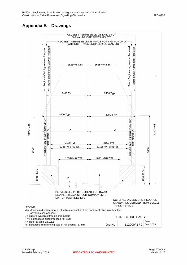
RailCorp Engineering Specification — Signals — Construction Specification Construction of Cable Routes and Signalling Civil Works SPG 0705
Appendix B Drawings
1700+M+0.75S1700+M-0.75S
S
(2135+M-SH/1435) (2135+M+SH/1435)
AA
1065
-0.7
S
3800
6100
-0.6
S
1065
+1.7
S38
00
PER
MIS
SA
BLE
INFR
ING
EM
EN
TFO
R S
IGN
ALS
PER
MIS
SA
BLE
INFR
ING
EM
ENT
FOR
SIG
NAL
S
PERMISSIBLE INFRINGEMENT FOR DWARFSIGNALS, TRACK CIRCUIT COMPONENTSSWITCH MACHINES ETC
LEGENDM = Maximum displacement of of vehicle centreline from track centreline in millimeters For values see oppositeS = superelevation of track in millimetersH = Height above final proposed rail levelA = Refer to table 26.2.1.1For distances from running face of rail deduct 717 mm
1525+M-4.3S 1525+M+4.3S
STRUCTURE GAUGE
Drg No 112000/ 1 / 2DateDec 2009
3000 Typ 3000 TYP
2400 Typ 2400 Typ
Reg
iona
l Civ
il A
gree
men
t Req
uire
d
6100
+1.6
S
Trac
k E
ngin
eerin
g W
aive
r Req
uire
d
2150 Typ 2150 Typ
Reg
iona
l Civ
il A
gree
men
t Req
uire
d
Trac
k E
ngin
eerin
g W
aive
r Req
uire
d
CLOSEST PERMISSIBLE DISTANCE FOR SIGNALS ONLY
CLOSEST PERMISSIBLE DISTANCE FORSIGNAL BRIDGE FOOTINGS ETC
(WITHOUT TRACK ENGINEERING WAIVER)
NOTE: ALL DIMENSIONS & SOURCESTANDARDS DERIVED FROM ESC215TRANSIT SPACE
© RailCorp Page 67 of 82 Issued 8 February 2013 UNCONTROLLED WHEN PRINTED Version 1.17

RailCorp Engineering Specification — Signals — Construction Specification Construction of Cable Routes and Signalling Civil Works SPG 0705
© RailCorp Page 68 of 82 Issued 8 February 2013 UNCONTROLLED WHEN PRINTED Version 1.17
Mid-ordinate Values “M”
M(mm) = 42000/R where R = radius of curve in metres
R M R M R M 100 420 240 175 700 60 120 350 260 162 800 53 140 300 280 150 900 47 160 260 300 140 1000 42 180 233 400 105 1500 28 200 210 500 84 2000 21 220 190 600 70 3000 14
Minimum Clearance to Structures – Dimension “A”
Structures adjacent to main lines
“A” =
3000 Overhead wiring masts, signal gantries, columns between tracks. 4300 Columns outside tracks
5000 All other structures located adjacent to electrified lines where road access is not required
5500 All other structures located adjacent to non-electrified lines where road access is required.
6200 All other structures located adjacent to electrified lines where road access is required.
Structures adjacent to sidings
“A” =
2500 Overhead wiring masts, signal gantries, isolated columns. 3000 Continuous structures. 3700 Where rail vehicle doors open opposite structures.
Refer to ESC 215
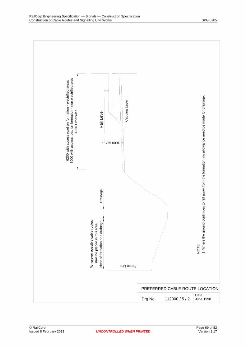
RailCorp Engineering Specification — Signals — Construction Specification Construction of Cable Routes and Signalling Civil Works SPG 0705
PREFERRED CABLE ROUTE LOCATION
Drg No 112000 / 5 / 2
4250
Oth
erw
ise
clea
r of f
orm
atio
n an
d dr
aina
ge
Whe
reve
r pos
sibl
e ca
ble
rout
essh
all b
e pl
aced
in th
is a
rea
Dra
inag
e
6200
with
acc
ess
road
on
form
atio
n - e
lect
rifie
d ar
eas
5000
with
acc
ess
road
on
form
atio
n - n
on e
lect
rifie
d ar
es
Rai
l Lev
el
1600 min
Cap
ping
Lay
er
Fence Line
NO
TE1
Whe
re th
e gr
ound
con
tiniu
es to
fall
away
from
the
form
atio
n, n
o al
low
ance
nee
d be
mad
e fo
r dra
inag
e.
DateJune 1998
© RailCorp Page 69 of 82 Issued 8 February 2013 UNCONTROLLED WHEN PRINTED Version 1.17

RailCorp Engineering Specification — Signals — Construction Specification Construction of Cable Routes and Signalling Civil Works SPG 0705
clea
r of f
orm
atio
n an
d dr
aina
geC
atch
Dra
in
DateJune 1998
PREFERRED CABLE ROUTE LOCATION
Drg No 112000 / 5 / 3
Var
ies
Whe
reve
r pos
sibl
e ca
ble
rout
essh
all b
e pl
aced
in th
is a
rea
Rai
l Lev
el
1600 min
Cap
ping
Lay
er
NO
TES
Whe
re th
e ca
tch
drai
n is
not
requ
ired,
the
rout
e m
ay b
e la
id 7
50m
m fr
om th
e to
p if
GLT
or 1
200m
m if
bur
ied
rout
e
© RailCorp Page 70 of 82 Issued 8 February 2013 UNCONTROLLED WHEN PRINTED Version 1.17

RailCorp Engineering Specification — Signals — Construction Specification Construction of Cable Routes and Signalling Civil Works SPG 0705
Signalling Cables
Spare Pipe(s)
Clean fill
Earth wire
Marker Tape
separatorother suitableCover strip or
HV power Cable(s)
Separation as required by ACA
800 minimum
White pipe for communications cable
Cover strip
50
(if required)
300
(Only installed in non-electrified area.)
(Only installed in non-electrified area.)
BURIED CABLE ROUTE TYPES 1, 2 AND 3
Drg No 112000 / 5 / 4
TYPE 1 CABLE ROUTE
TYPE 2 CABLE ROUTE WITHOUT PITSTYPE 3 CABLE ROUTE WITH PITS AT 300m INTERVALS
DateJuly 2004
Signalling Cables
Earth wire
Marker Tape
Clean fill
separatorother suitableCover strip or
HV power Cable(s)
Separation as required by ACA.
800 minimum
White pipe for communications cable
Cover strip
50
(if required)
300
© RailCorp Page 71 of 82 Issued 8 February 2013 UNCONTROLLED WHEN PRINTED Version 1.17
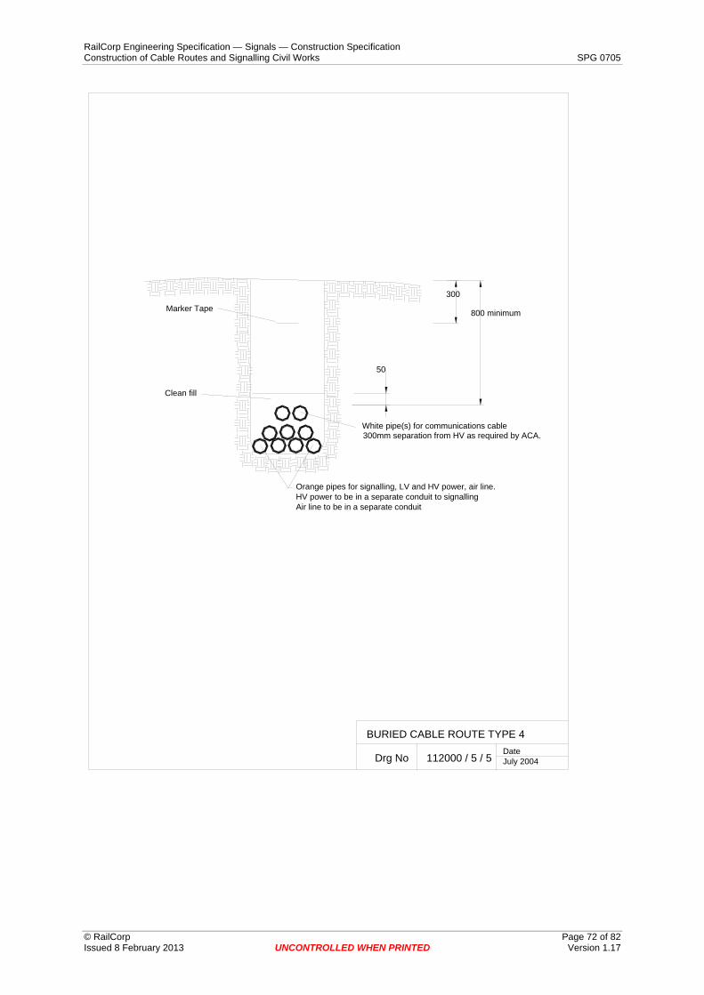
RailCorp Engineering Specification — Signals — Construction Specification Construction of Cable Routes and Signalling Civil Works SPG 0705
BURIED CABLE ROUTE TYPE 4
Drg No 112000 / 5 / 5DateJuly 2004
Orange pipes for signalling, LV and HV power, air line.
Air line to be in a separate conduitHV power to be in a separate conduit to signalling
Marker Tape
Clean fill
300mm separation from HV as required by ACA.
800 minimum
White pipe(s) for communications cable
50
300
© RailCorp Page 72 of 82 Issued 8 February 2013 UNCONTROLLED WHEN PRINTED Version 1.17

RailCorp Engineering Specification — Signals — Construction Specification Construction of Cable Routes and Signalling Civil Works SPG 0705
BURIED CABLE IN ROCK
Drg No 112000 / 5 / 6
Sand/cement mix (3:1)(Concrete if in an access road)
Clean fill
Earth wireMarker Tape
Sand Separation as required by ACA
300 minimum
White pipe(s) for communications cable
50
100 min
IN ROCK
CHASED IN SOLID ROCK
(Not required if the bottom of the trench is free of rough or sharp projections)
Date July 2004
Sand/cement mix (3:1)(Concrete if in an access road)
Clean fill
Earth wire
Marker Tape
Sand
Separation as required by ACA
600 minimum
White pipe(s) for communications cable
50
300
(Only installed in non electrified area.)
(Only installed in non electrified area.)
© RailCorp Page 73 of 82 Issued 8 February 2013 UNCONTROLLED WHEN PRINTED Version 1.17

RailCorp Engineering Specification — Signals — Construction Specification Construction of Cable Routes and Signalling Civil Works SPG 0705
Con
cret
e
Met
al e
nd c
over
sec
ured
to G
LT li
d
Trou
ghin
g lid
cut
and
ben
t par
alle
lto
GLT
lid
22.5 max
Stee
l tro
ugh
tar e
poxy
coa
ted
to 1
50m
m a
bove
gro
und
DateJune 1998
GST / GLT INTERFACE
Drg No 112000 / 8 / 1
© RailCorp Page 74 of 82 Issued 8 February 2013 UNCONTROLLED WHEN PRINTED Version 1.17

RailCorp Engineering Specification — Signals — Construction Specification Construction of Cable Routes and Signalling Civil Works SPG 0705
GST / BURIED ROUTE INTERFACE
Drg No 112000 / 8 / 2
22.5 max
Inve
rted
conc
rete
GLT
or d
uct
seal
ed a
roun
d st
eel t
roug
h w
ithsa
nd/c
emen
t mix
afte
r cab
le in
stal
latio
n
Cov
er s
trip
Ste
el tr
ough
tar e
poxy
coa
ted
1200
hig
h bo
llard
s ap
prox
500
mm
eith
ersi
de o
f con
cret
e du
ct.
Req
uire
d w
here
ver v
ehic
ular
traf
fic is
pos
sibl
e
to 1
50m
m a
bove
gro
und
leve
l
GLT
or d
uct b
edde
d on
sta
bilis
ed s
and
or s
and/
cem
ent m
ix
DateJune 1998
© RailCorp Page 75 of 82 Issued 8 February 2013 UNCONTROLLED WHEN PRINTED Version 1.17

RailCorp Engineering Specification — Signals — Construction Specification Construction of Cable Routes and Signalling Civil Works SPG 0705
Con
cret
e
Met
al e
nd c
over
sec
ured
to G
LT li
d
Trou
ghin
g lid
cut
and
ben
t par
alle
lto
GLT
lid
22.5 max
Ste
el tr
ough
tar e
poxy
coa
ted
to 1
50m
m a
bove
gro
und
PIT
Pit
prot
ecte
d by
120
0 hi
gh b
olla
rds
appr
ox 5
00m
m e
ither
sid
e of
pit
whe
reve
r veh
icul
ar tr
affic
is p
ossi
ble
(Exc
ept w
here
GS
T co
ntin
ues
on th
eop
posi
te s
ide
of th
e pi
t)
DateJune 1998
GST TO PIT INTERFACE
Drg No 112000 / 8 / 3
© RailCorp Page 76 of 82 Issued 8 February 2013 UNCONTROLLED WHEN PRINTED Version 1.17

RailCorp Engineering Specification — Signals — Construction Specification Construction of Cable Routes and Signalling Civil Works SPG 0705
BURIED ROUTE TO LOCATION CASE
Drg No 112000 / 14 / 1
Bol
lard
s w
here
veh
icul
ar tr
affic
is p
ossi
ble
Con
cret
e pa
d 10
00 w
ide
x 10
0 th
ick
arou
nd lo
catio
n ca
se
Add
ition
al 3
met
res
of c
able
coile
d in
side
bas
e
300
min
If th
e lo
catio
n ca
seba
se is
not
cap
tive
unde
r the
sla
b,th
e ba
se s
hall
be a
min
imum
off
400m
min
gro
und
TYPICAL ARRANGEMENT
As
show
n fo
r sta
ble,
leve
l gro
und.
Foo
tings
, ret
aini
ng w
alls
, acc
ess
path
s/st
eps/
ladd
ers
as re
quire
d.
Cable
Stainless steel earth wire
and
earth
wire
DateJune 1998
© RailCorp Page 77 of 82 Issued 8 February 2013 UNCONTROLLED WHEN PRINTED Version 1.17

RailCorp Engineering Specification — Signals — Construction Specification Construction of Cable Routes and Signalling Civil Works SPG 0705
GLT TO LOCATION CASE
Drg No 112000 / 14 / 2
Bolla
rds
whe
re v
ehic
ular
traf
fic is
pos
sibl
e
Con
cret
e pa
d 10
00 w
ide
x 10
0 th
ick
arou
nd lo
catio
n ca
se
Addi
tiona
l 3 m
etre
s of
cab
leco
iled
insi
de b
ase
GLT
300
min
If th
e lo
catio
n ca
seba
se is
not
cap
tive
unde
r the
sla
b,th
e ba
se s
hall
be a
min
imum
off
400m
min
gro
und
TYPICAL ARRANGEMENT
As
show
n fo
r sta
ble,
leve
l gro
und.
Foo
tings
, ret
aini
ng w
alls
, acc
ess
path
s/st
eps/
ladd
ers
as re
quire
d.
DateJune 1998
© RailCorp Page 78 of 82 Issued 8 February 2013 UNCONTROLLED WHEN PRINTED Version 1.17
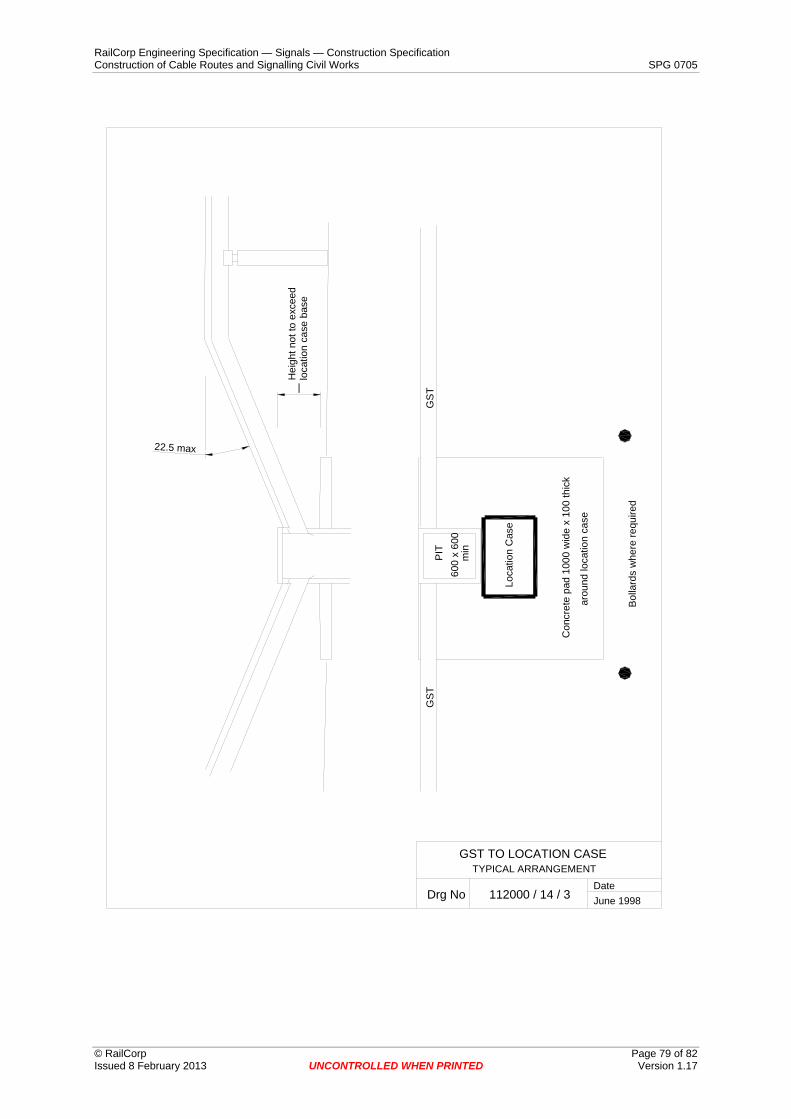
RailCorp Engineering Specification — Signals — Construction Specification Construction of Cable Routes and Signalling Civil Works SPG 0705
Hei
ght n
ot to
exc
eed
loca
tion
case
bas
e
GST TO LOCATION CASE
Drg No 112000 / 14 / 3
Con
cret
e pa
d 10
00 w
ide
x 10
0 th
ick
arou
nd lo
catio
n ca
se
TYPICAL ARRANGEMENT
22.5 max
Bol
lard
s w
here
requ
ired
PIT
600
x 60
0
Loca
tion
Cas
e
GS
TG
ST
min
DateJune 1998
|
© RailCorp Page 79 of 82 Issued 8 February 2013 UNCONTROLLED WHEN PRINTED Version 1.17

RailCorp Engineering Specification — Signals — Construction Specification Construction of Cable Routes and Signalling Civil Works SPG 0705
Appendix C ATP Installation Drawings
© RailCorp Page 80 of 82 Issued 8 February 2013 UNCONTROLLED WHEN PRINTED Version 1.17
LEU
Junction Box
Existing Cable Pit
FIXEDBALISE
CONTROLLEDBALISE
TRACK
120V
To
Infil
l
To
Bal
ise
SIGNALLING HUT/CABINET
LEUTo
Bal
ise
120V
Inputs Inputs
LEU
INFILLBALISE
EXAMPLE
New conduit
FIXEDBALISE
CONTROLLEDBALISE
TRACK
INFILLBALISE
EXAMPLE
To
Infil
l
New conduit
New cable pits & conduits where required.
120V supply to LEUNew Conduit LEU inputsExisting Route
LEGEND
Cable Troughing
ULX
Junction BoxJunction BoxExample: 2 balise are fed from 2 separate cables
Figure 3 Multi Track showing ULX crossing with separate trunk cables

RailCorp Engineering Specification — Signals — Construction Specification Construction of Cable Routes and Signalling Civil Works SPG 0705
LEU
FIXEDBALISE
CONTROLLEDBALISE
Junction Box
FIXEDBALISE
CONTROLLEDBALISE
TRACK
120V
To
Infil
l
To
Bal
ise
SIGNALLING HUT/CABINET
LEUTo
Bal
ise
120V
Inputs Inputs
LEU120V supply to LEUNew Conduit LEU inputsExisting Route
LEGEND
Cable Troughing
New conduit.
INFILLBALISE
EXAMPLE
Access to cable route via new cable pit where required.
Tail cable (surface run)
New conduits.
Existing Cable Route
New conduit
© RailCorp Page 81 of 82 Issued 8 February 2013 UNCONTROLLED WHEN PRINTED Version 1.17
Figure 4 Balise cable run example showing use of cable troughing
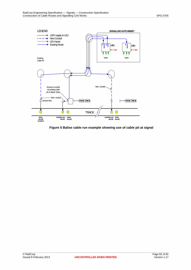
RailCorp Engineering Specification — Signals — Construction Specification Construction of Cable Routes and Signalling Civil Works SPG 0705
LEU
FIXEDBALISE
CONTROLLEDBALISE
Junction Box
Existing Cable Pit
FIXEDBALISE
CONTROLLEDBALISE
TRACK
120V
To
Infil
l
To
Bal
ise
SIGNALLING HUT/CABINET
LEUTo
Bal
ise
120V supply to LEUNew Conduit LEU inputsExisting Route
LEGEND
120V
LEU
Inputs Inputs
New conduitAccess to conduit via existing cable
pit at Signal Base
New conduit
INFILLBALISE
EXAMPLE
© RailCorp Page 82 of 82 Issued 8 February 2013 UNCONTROLLED WHEN PRINTED Version 1.17
Figure 5 Balise cable run example showing use of cable pit at signal