technical manual · technical manual operator's manual for carrier, ammunition, tracked,...
TRANSCRIPT

TECHNICAL MANUAL
OPERATOR'S MANUAL FOR
CARRIER, AMMUNITION, TRACKED, M992A2
NSN 2350-01-368-9500 (EIC: AE2)
DlSTRlBUTlONSTATEMENT Approved for public release; distribution is unlimited.
SUPERSEDURE NOTICE: This manual supersedes TM 9-2350-293-10 dated November 1994, including all changes.
HEADQUARTERS DEPARTMENT OFTHE ARMY
DECEMBER 2001


WARNING SUMMARY
This Warning Summary contains general safety warnings and hazardousmaterials warnings that must be understood and applied during operation andmaintenance of the Field Artillery Ammunition Support Vehicle (FAASV).Failure to observe these precautions could result in serious injury or death.
The following is a list of explanations of the safety and hazardous materialsicons used in the Warning Summary.
EXPLANATION OF SAFETY WARNING ICONS
EAR PROTECTION: Headphones over ears shows that noiselevel will harm ears.
ELECTRICAL – Electrical wire to arm with electricitysymbol running through human body shows that shockhazard is present.
ELECTRICAL – Electrical wire to hand with electricitysymbol running through hand shows that shock hazard ispresent.
FALLING PARTS: Arrow bouncing off human shoulder andhead shows that falling parts present a danger to life or limb.
FLYING PARTICLES: Arrows bouncing off face show thatparticles flying through the air will harm face.
a
TM 9-2350-293-10

WARNING SUMMARY (continued)
EXPLANATION OF SAFETY WARNING ICONS (continued)
HEAVY OBJECT: Human figure stooping over heavy objectshows physical injury potential from improper liftingtechnique.
HEAVY PARTS: Hand with heavy object on top shows thatheavy parts can crush and harm.
HEAVY PARTS: Foot with heavy object on top shows thatheavy parts can crush and harm.
HEAVY PARTS: Heavy object on human figure shows thatheavy parts present a danger to life or limb.
HEAVY PARTS: Heavy object pinning human figure againstwall shows that heavy, moving parts present a danger to lifeor limb.
HELMET PROTECTION: Arrow bouncing off head withhelmet shows that falling parts present a danger.
b
TM 9-2350-293-10

WARNING SUMMARY (continued)
EXPLANATION OF SAFETY WARNING ICONS (continued)
HOT AREA: Hand over object radiating heat shows that partis hot and can burn.
MOVING PARTS: Human figure with arm caught betweengears shows that the moving parts of the equipment present adanger to life or limb.
MOVING PARTS: Hand with fingers caught between gearsshows that the moving parts of the equipment present a dangerto life or limb.
MOVING PARTS: Hand with fingers caught between rollersshows that the moving parts of the equipment present a dangerto life or limb.
SHARP OBJECT: Pointed object in hand shows that a sharpobject presents a danger to limb.
SHARP OBJECT: Pointed object in hand shows that a sharpobject presents a danger to limb.
c
TM 9-2350-293-10

WARNING SUMMARY (continued)
EXPLANATION OF SAFETY WARNING ICONS (continued)
SHARP OBJECT: Pointed object in foot shows that a sharpobject presents a danger to limb.
SLICK FLOOR: Wavy line on floor with legs prone showsthat slick floor presents a danger of falling.
BIOLOGICAL: Abstract symbol bug shows that a materialmay contain bacteria or viruses that present a danger to life orhealth.
CHEMICAL: Drops of liquid on hand show that the materialwill cause burns or irritation to human skin or tissue.
EXPLOSION: Rapid expansion symbol shows that thematerial may explode if subjected to high temperatures,sources of ignition, or high pressure.
VAPOR: Human figure in a cloud shows that material vaporspresent a danger to life or health.
d
TM 9-2350-293-10

WARNING SUMMARY (continued)
EXPLANATION OF SAFETY WARNING ICONS (continued)
FIRE: Flame shows that a material may ignite and causeburns.
POISON: Skull and crossbones show that a material ispoisonous or is a danger to life.
RADIATION: Three circular wedges show that the materialemits radioactive energy and can injure human tissue.
EYE PROTECTION: Person with goggles shows that thematerial will injure the eyes.
e
TM 9-2350-293-10

.
WARNING SUMMARY (continued)
CARBON MONOXIDE HAZARDS
WARNING
CARBON MONOXIDE (EXHAUST GAS) CAN KILL YOU.
WARNING
Carbon monoxide is a colorless, odorless, DEADLY POISONOUS gas. When breathed, itdeprives the body of oxygen and causes SUFFOCATION. Breathing air with carbonmonoxide produces symptoms of headache, dizziness, loss of muscular control, a sleepyfeeling, and coma. Permanent BRAIN DAMAGE or DEATH can result from seriousexposure.
The following precautions MUST be followed to make sure personnel are safe wheneverpersonnel heater, main engine, or auxiliary engine is operated for any purpose.
• DO NOT operate personnel heater or engine of vehicle in enclosed area without adequateventilation.
• DO NOT idle engine for long periods without ventilator blower operating. If tacticalsituation permits, open hatches.
• DO NOT drive any vehicle with inspection plates, cover plates, or engine compartmentdoors removed unless necessary for maintenance purposes.
• NEVER sleep in a vehicle when the heater is operating or the engine is idling.
• BE ALERT at all times during vehicle operation for exhaust odors and exposure symptoms.If either is present, IMMEDIATELY EVACUATE AND VENTILATE the area. Treatmentfor affected personnel shall be: Expose to fresh air; keep warm; DO NOT PERMITPHYSICAL EXERCISE; if necessary, give artificial respiration as described in FM 21-11;and get medical attention.
• BE AWARE: Neither the gas particulate filter unit nor the field protection mask fornuclear-biological-chemical protection will protect you from carbon monoxide poisoning.
WARNING
THE BEST DEFENSE AGAINST CARBON MONOXIDE POISONING IS GOODVENTILATION.
f
TM 9-2350-293-10

WARNING SUMMARY (continued)
BATTERY HAZARDS
WARNING
Lead-acid batteries can explode. Do not smoke, have open flames, or make sparks arounda battery, especially if the caps are off. If a battery is giving off gas, it can explode and causeinjury to personnel.
WARNING
Ventilate area when charging or using battery in an enclosed space.
WARNING
Wear safety goggles and acid-proof gloves when battery cover must be removed or whenchecking electrolyte level.
WARNING
Avoid contact between battery electrolyte and skin, eyes, or clothing. If electrolyte spills,take immediate action to stop burning effects:
• External. Immediately flush with cold running water to remove all acid.
• Eyes. Flush with cold water for at least 15 minutes. Seek immediate medical attention.
• Internal. Drink large amounts of water or milk. Follow with milk of magnesia, beatenegg, or vegetable oil. Seek immediate medical attention.
• Clothing or Vehicle. Wash at once with cold water. Neutralize with baking soda orhousehold ammonia solution.
WARNING
Wear safety glasses or goggles when checking batteries. Always check electrolyte level withengine stopped. Do not smoke or use exposed flame when checking battery; explosive gasesare present and severe injury to personnel can result.
g
TM 9-2350-293-10

WARNING SUMMARY (continued)
BATTERY HAZARDS (continued)
WARNING
Remove or disconnect batteries or turn off master battery disconnect switch prior toperforming maintenance in immediate battery area and prior to working on electrical system.Such disconnections prevent electrical shock to personnel or equipment.
WARNING
Battery acid (electrolyte) is extremely harmful. Always wear safety goggles and rubbergloves, and do not smoke when performing maintenance on batteries. Injury will result ifacid contacts skin or eyes. Wear rubber apron to prevent damage to clothing.
WARNING
Before working with batteries, remove all jewelry, such as rings, identification tags,bracelets, and so on. If jewelry contacts battery terminal, a direct short may result in instantheating of tools, damage to equipment, and injury or death to personnel.
WARNING
When removing batteries, always disconnect ground cables first. Failure to do so may resultin injury or death to personnel.
WARNING
When checking connections, do not let tools touch battery box. A direct short, arcing, toolheating to red hot, or battery explosion may result, causing injury or death to personnel.
WARNING
HEAT/COLD ACTIVITY HAZARD
Requirements for Water Intake and Work/Rest Cycles
Leaders and supervisors must be aware of the potential for heat and cold injuries. Forprevention guidelines, refer to local procedures and to TB MED 507 and TB MED 81.
h
TM 9-2350-293-10

WARNING SUMMARY (continued)
GENERAL OPERATION HAZARDS
WARNING
When traveling over rough terrain, soft ground, or wet/icy surfaces, slow down and shift toa lower gear. When driving on a floor, dock, or bridge, ensure that combined weights ofmachine and load do not exceed safe limit. Check for sufficient overhead clearance.
WARNING
Do not back up vehicle without ground guide. Limited vision can lead to vehicle damageand injury to personnel. Use at least two ground guides when backing; if only one guide isused, stop operations if communications between driver and ground guide are interrupted.
WARNING
Do not let vehicle coast downhill with transmission in the “N” (neutral) position. Vehiclemay increase speed and go out of control, resulting in injury or death to personnel.
WARNING
If you lose a track (break a track shoe or vehicle throws a track), extreme caution must beexercised in maintaining control. Immediately release accelerator pedal and let vehicle coastto a stop. Do not apply braking action, brake pedal, laterals, pivots, or any type of steeringcontrols. Braking causes vehicle to pull to the active, or good, track and could result in arollover. If absolutely necessary, apply braking action ONLY if the vehicle is approachinga ravine or cliff or if you perceive the outcome to be catastrophic, probably resulting infatalities. When rollover is imminent, all crew members should immediately withdrawinside vehicle, tighten seatbelts, and hold onto a secure fixture until vehicle comes to acomplete stop.
WARNING
The area must be clear of personnel before operating the vehicle.
i
TM 9-2350-293-10

WARNING SUMMARY (continued)
GENERAL OPERATION HAZARDS (continued)
WARNING
When operating the vehicle, observe the following precautions:
• Always drive carefully. Drive with extra caution until you can operate the equipment withskill.
• Do not move vehicle until all doors and hatches are secured and all equipment is properlystowed.
• Never move vehicle without first receiving a signal from the ammunition team chief.
WARNING
Do not block engine air intake grille with camouflage or other materials.
WARNING
Do not operate engine at idle for more than 10 minutes. Using hand throttle at fast idle setting(1000 rpm) will help reduce engine overheating.
TOWING HAZARD
WARNING
When hooking or unhooking towbar or tow cable from a disabled vehicle, set parking brakeor chock tracks of disabled vehicle before hooking or unhooking towbar or tow cable. Iftowed vehicle is not chocked or parking brake is not set, disabled vehicle may move, causinginjury or death to personnel and/or damage to equipment.
j
TM 9-2350-293-10

WARNING SUMMARY (continued)
FUEL-HANDLING HAZARDS
WARNING
Fuel is very flammable and can explode easily. To avoid serious injury or death, keep fuelaway from open flame or any spark (ignition source).
WARNING
Never allow flame or any smoking within 50 feet of fueling operations.
WARNING
Fuel is very flammable and can explode easily. To avoid serious injury or death, post signsthat read NO SMOKING WITHIN 50 FEET OF VEHICLE when working with open fuel,fuel lines, or fuel tanks.
WARNING
Fuel is very flammable and can explode easily. To avoid serious injury or death:
• Keep at least a B-C fire extinguisher within easy reach when working with fuel or fuelsystem.
• Do not work on fuel system when engine is hot; fuel can be ignited by a hot engine.• Clean fuel tank to purge any flammable liquid or vapors before welding, grinding, or using
any heat-producing device near the fuel tank.
WARNING
Fuel is very flammable and can explode easily. To avoid serious injury or death whenrefueling, stop vehicle, shut down engine, and apply parking brake. Make sure no open flameis near area. Never smoke. Never add fuel with engine running. Do not have driver seatedwhen adding fuel. After fuel is added, securely close reservoir cap; a loose cap can causea fuel leak or be a fire hazard. Before starting vehicle, check to see that no fuel is spilled onor around vehicle.
WARNING
Ground fuel funnel or nozzle against filler neck to prevent sparks, and be sure to replace fueltank cap.
k
TM 9-2350-293-10

WARNING SUMMARY (continued)
PERSONNEL HEATER HAZARDS
WARNING
If heater operates improperly fuel may overflow, causing danger of fire or explosion.
WARNING
Be alert during heater operation for exhaust odors or signs of exposure to carbon monoxide.Carbon monoxide can kill you. If you suspect that carbon monoxide is present, shut off heaterand ventilate vehicle.
WARNING
Do not place flammable materials or explosives on or near personnel heater. To preventinjury to personnel and damage to equipment, do not block or restrict heater vent.
WARNING
Do not use vehicle MASTER switch to shut down heater, as fuel vapors may accumulate inventilating air circuit.
FIRE EXTINGUISHER (CO2) HAZARDS
WARNING
Remain CALM. Avoid breathing CO2. It may quickly cause rapid breathing, loss of
consciousness, and suffocation. Quickly exit vehicle if situation permits. If unable to exit,ventilate to remove the extinguisher gas. The driver is at the greatest risk. Ventilate thevehicle before reentry. Failure to follow this emergency procedure can result in serious injuryor death to personnel.
l
TM 9-2350-293-10

WARNING SUMMARY (continued)
FIRE EXTINGUISHER (CO2) HAZARDS (continued)
WARNING
Fire extinguisher CO2
can cause severe burns. Do not touch the cone when using fireextinguisher or discharge directly on skin.
WARNING
Handle fire extinguisher carefully. Do not bang or drop cylinder.
AUTOMATIC FIRE EXTINGUISHING SYSTEM (AFES) HAZARDS
WARNING
Any automatic fire extinguishing system (AFES) unit in need of maintenance or repair isextremely prone to accidental discharge, which could lead to frostbite or other injury. Smallparts or tools become dangerous projectiles when propelled by Halon discharging at 750 psi(5171 kPa). Do not strike fire extinguisher bottles with tools, and do not drop fireextinguisher bottles. To prevent accidental discharge, be careful when handling fireextinguisher bottles.
CONVEYOR HAZARDS
WARNING
m
TM 9-2350-293-10

WARNING SUMMARY (continued)
CONVEYOR HAZARDS (continued)
Be careful when deploying, operating, and stowing conveyor. Failure to observe thefollowing precautions may result in severe injury to personnel:
• Keep hands and body parts clear of moving parts of conveyor.• Keep fingers clear of section hinges when deploying conveyor.• Make sure footing is firm and deployment area is free of obstructions. Be prepared to stand
to one side and move quickly after conveyor begins to move.• Be prepared to move quickly; conveyor deploys rapidly. Make sure door is positioned
properly to control deployment speed.• Have an assistant hold conveyor in stowed position while safety strap is removed or
installed.• Be careful to keep conveyor from swinging left or right.• Do not operate conveyor with chain guards removed.• Make sure conveyor slings are properly attached.• Do not drop or throw projectiles onto conveyor. Promptly remove projectiles and
propelling charges from conveyor.• Attach ground strap to truck or stockpile.
WARNING
When operating with upper rear door open, always engage mechanical safety lock beforebeginning conveyor operations. This will prevent upper rear door from dropping if hydraulicsystem fails.
PROJECTILE RACK ASSEMBLY HAZARDS
WARNING
n
TM 9-2350-293-10

WARNING SUMMARY (continued)
Before moving projectile rack assemblies, park vehicle on level ground. If vehicle is notlevel, projectile racks may tip, causing injury or death to personnel or damage to equipment.
WARNING
Before moving projectile rack assembly toward rear of vehicle, make sure floor will providea level resting place. If floor is not level rack may tip, causing injury or damage.
WARNING
If both projectile rack assemblies are to be moved, move right assembly first. After leftprojectile rack assembly is moved, leave hoisting hook attached; this support is necessarybecause the assemblies tend to tip forward when both are moved back.
AMMUNITION HAZARDS
WARNING
Ammunition carrying explosives must be handled with care at all times. The explosive inprimers and fuses is very sensitive to shock and high temperatures. Keep ammunition awayfrom heaters. If ammunition is dropped, heated, thrown, tumbled, or dragged, an explosionmay result, causing death or injury to personnel and destruction of equipment. Disassemblyof ammunition is not authorized.
WARNING
Always attach grounding cable to howitzer, truck, or stockpile before unloading ammunition.Failure to do this may result in explosion of ammunition.
WARNING
Handle projectiles carefully. Contact between projectiles and fire extinguisher could causeextinguisher to discharge, resulting in injury to personnel or damage to vehicle.
WARNING
To avoid injury to back, hands, and feet, use caution and proper lifting techniques whenmanually handling projectiles.
o
TM 9-2350-293-10

WARNING SUMMARY (continued)
HEAVY PARTS HAZARDS
WARNING
WARNING
Many vehicle components, such as seats, doors, universal joints, and track, are very heavyand should be handled carefully. Have an assistant help when lifting heavy components.
WARNING
Universal joints are heavy. Keep hands out from underneath universal joints when they aredisconnected. Failure to do so may result in injury to personnel.
WARNING
Commander's seat assembly is very heavy. It must be adequately supported before quick-release pin is removed. Failure to do so may result in serious injury. Deployment ofcommander's seat shall always be a two-person operation.
WARNING
Seats are heavy. Support seats before pulling quick-release pins. Hinged seats, backrests,and support brackets may swing down, causing personal injury.
WARNING
Battery access doors, transmission access doors, and auxiliary power unit side door are veryheavy. Keep hands clear when opening or closing doors.
WARNING
Upper rear door is very heavy. Keep feet and hands clear of doorway when opening orclosing door.
p
TM 9-2350-293-10

WARNING SUMMARY (continued)
WARNING
Track is very heavy. Keep hands and feet from beneath track while it is being lifted.
WARNING
Duffle bag shelves are heavy. To avoid serious injury, stand clear of shelf when it is beingdeployed.
UPPER REAR DOOR HAZARDS
WARNING
Upper rear door is very heavy. Three persons (one inside the vehicle and two outside thevehicle) are reuired to open or close it manually. Injury may result from attempting thisprocedure alone.
WARNING
Stand clear when opening or closing upper rear door (ballistic shield). If you open or closethis door from outside the vehicle (using bottom switch), keep head and shoulders out of doortravel path.
WARNING
Make sure travel path of upper rear door is clear of personnel before opening or closing door.Call out “CLEAR” when opening or closing door to prevent personnel from stepping in frontof door.
WARNING
During normal operations, the mechanical safety lock should be used when positioning thedoor. The lock supports the door if the hydraulic safety mechanism fails.
q
TM 9-2350-293-10

WARNING SUMMARY (continued)
HIGH-INTENSITY NOISE HAZARDS
WARNING
Protect your hearing. Due to high-intensity noise, hearing protection is required whenoperating this vehicle.
WARNING
High-intensity noise, hearing protection required. Hearing can be PERMANENTLYDAMAGED if a person is exposed to constant high noise levels of 85 decibels or greater.
WARNING
During operation of main engine or auxiliary power unit, decibel levels exceed safe levelsfor human hearing. Wear approved hearing protection devices when working in high noiselevel areas. Failure to do so could result in injury to personnel.
WARNING
Personnel within 38 yards (35 m) of the machine gun must wear approved single hearingprotection (e.g., earplugs) when the machine gun is being fired. Failure to do so could resultin injury to personnel.
WARNING
Personnel within 689 yards (630 m) of the howitzers must wear approved hearing protectionduring firing. Follow the hearing protection warnings and obey the hazard zones identifiedin TM 9-2350-314-10. Failure to do so could result in injury to personnel.
WARNING
Personnel within nine yards (8 m) of the vehicle must wear approved single hearingprotection when the main engine or auxiliary power unit is running. Failure to do so couldresult in injury to personnel.
r
TM 9-2350-293-10

WARNING SUMMARY (continued)
WARNING
Operation of the vehicle is limited to 68 miles (110 km) per 24-hour period for crews wearingthe H-374 (VIC-3) combat vehicular crewman (CVC) helmet with the Active NoiseReduction (ANR) on. Operation is limited to 8 miles (13 km) per 24-hour period for crewswearing the H-374 (VIC-3) CVC with the ANR off. If the mission exceeds the recommendeddistances for a 24-hour period, double hearing protection (e.g., earplugs and CVC) must beworn. Failure to do so could result in injury to personnel.
SOLVENT P-D-680 HAZARDS
WARNING
Drycleaning solvent (P-D-680) is TOXIC and flammable. Wear protective goggles andgloves; use only in a well-ventilated area; avoid contact with skin, eyes, and clothes; and donot breathe vapors. Keep away from heat or flame. Never smoke when using drycleaningsolvent. Failure to follow this warning may result in injury or death to personnel.
WARNING
If personnel become dizzy while using drycleaning solvent, immediately get fresh air andmedical help. If solvent contacts skin or clothes, flush with cold water. If solvent contactseyes, immediately flush them with water and get immediate medical attention.
WARNING
When P-D-680 drycleaning solvent is used, notify the local medical authority (preventivemedicine) and environmental coordinator concerning medical surveillance, respiratoryprotection, and disposal requirements.
s
TM 9-2350-293-10

WARNING SUMMARY (continued)
CHEMICAL AGENT RESISTANT COATING (CARC) HAZARD
WARNING
Unusable chemical agent resistant coating (CARC) mixtures are considered hazardous wasteand will require disposal in accordance with Federal, state, Department of Defense,Department of the Army, and local installation hazardous waste regulations. Consult theinstallation environmental office for proper disposal guidance. Mixed CARC is extremelyflammable. Use only in well-ventilated areas. Keep away from open flames, sparks, andother ignition sources.
NUCLEAR, BIOLOGICAL, OR CHEMICAL (NBC)EXPOSURE AND VEHICLE AIR FILTER HAZARDS
WARNING
NBC-contaminated air filters must be handled and disposed of only by authorized and trainedpersonnel. The unit commander or senior officer in charge of maintenance personnel mustensure that prescribed protective clothing (FM 3-4) is used and that prescribed safetymeasures and decontamination procedures (FM 3-5) are followed. The local unit’s standardoperating procedure is responsible for final disposal of contaminated air filters. Failure tocomply with this warning may cause severe injury to personnel.
WARNING
The NBC protection filters use a type of carbon that contains Chromium VI. This is a knowncarcinogen if inhaled or swallowed. Damaged or unusable filters are classified as hazardouswaste.
t
TM 9-2350-293-10

WARNING SUMMARY (continued)
• Do not throw away damaged or unusable filters as trash.• Turn in damaged or unusable filters to your Hazardous Waste Management Office or
Defense Reutilization and Marketing Office.
WARNING
If NBC exposure is suspected, all air filter media should be handled by personnel wearingprotective equipment. Consult your unit NBC officer or NBC NCO for appropriate handlingor disposal instructions.
WARNING
NBC-contaminated filters must be handled using adequate precautions and must be disposedof by trained personnel.
WARNING
Filters are completely safe to handle and use if they are not damaged in such a way that carbonleaks from them. If carbon does leak use protection, such as a dust respirator, to cover noseand mouth. Put carbon in a container, such as a self-sealing plastic bag, and turn it in to yourHazardous Waste Management Office or Defense Reutilization and Marketing Office.
WARNING
Disposal of hazardous waste is restricted by law. Violation is subject to criminal penalties.
u/v blank
TM 9-2350-293-10


TABLE OF CONTENTS
WARNING SUMMARY
HOW TO USE THIS MANUAL
GENERAL INFORMATION.............................................................................. 0001 00
CHAPTER 1 - DESCRIPTION AND THEORY OF OPERATIONEquipment Description and Data ............................................................. 0002 00Theory of Operation: Powerpack ........................................................... 0003 00Theory of Operation: Auxiliary Power Unit (APU) ............................... 0004 00Theory of Operation: Hydraulic Reservoir ............................................. 0005 00Theory of Operation: Ventilated Face Piece System (VFPS) ................. 0006 00Theory of Operation: Hydraulic Actuators and Related Components ... 0007 00Theory of Operation: Chemical Agent Detection and Alarm System .... 0008 00Theory of Operation: Hydraulic Control Panel ...................................... 0009 00
CHAPTER 2 - OPERATOR INSTRUCTIONSDescription and Use of Operator Controls and Indicators ...................... 0010 00Operation Under Usual Conditions ......................................................... 0011 00Starting Main Engine ............................................................................... 0012 00Portable Instrument Panel Checkout Procedure ...................................... 0013 00Operation of Dome Lights and Driving Lights ....................................... 0014 00Shifting the Transmission ........................................................................ 0015 00Driving the Vehicle ................................................................................. 0016 00Driving Over Rough, Soft, or Hilly Terrain ............................................ 0017 00Stopping the Vehicle ............................................................................... 0018 00Backing the Vehicle ................................................................................. 001900Towing Operations .................................................................................. 0020 00Operating the Bilge Pump ....................................................................... 0021 00Commander's Seat ................................................................................... 0022 00Rotating Commander's Cupola ................................................................ 0023 00Crew Seats ............................................................................................... 0024 00Operating the Auxiliary Power Unit (APU) ............................................ 0025 00Operating the Hydraulic Pump ................................................................ 0026 00Operating Doors ...................................................................................... 0027 00Operating Main Engine Air Cleaner System ........................................... 0028 00Ammunition Handling Equipment .......................................................... 0029 00Operating the Conveyor .......................................................................... 0030 00Propelling-Charge Stowage Areas ........................................................... 0031 00Projectile Rack Operation ........................................................................ 0032 00Operating Auxiliary Equipment .............................................................. 0033 00
iii
TM 9-2350-293-10
WP Sequence No.

TABLE OF CONTENTS (continued)
CHAPTER 2 (continued) WP Sequence No.
Stencil Markings ...................................................................................... 0034 00Nameplates and Decals ............................................................................ 0035 00Operation Under Unusual Conditions ..................................................... 0036 00Starting Main Engine in Cold Weather ................................................... 0037 00Slave Starting Disabled Vehicle Using Main Engine .............................. 0038 00Driving Over Unusual Terrain ................................................................. 0039 00Operating in Extreme Heat ...................................................................... 0040 00Operating in Humid or Salty Climates .................................................... 0041 00Operating in Dusty or Sandy Environments ............................................ 0042 00Fording Operations ................................................................................... 0043 00Emergency Procedures ............................................................................ 0044 00
CHAPTER 3 - TROUBLESHOOTING PROCEDURESIntroduction ............................................................................................. 0045 00Troubleshooting Index ............................................................................ 0046 00Troubleshooting Procedures .................................................................... 0047 00
CHAPTER 4 - MAINTENANCE INSTRUCTIONSPreventive Maintenance Checks and Services (PMCS) Introduction ..... 0048 00Table 2-1. PMCS for M992A2:
Before and During Operation ....................................................... 0049 00Table 2-1. PMCS for M992A2 (continued):
After Operation ............................................................................. 0050 00Table 2-1. PMCS for M992A2 (continued):
Weekly and Monthly Checks and Services .................................. 0051 00Engine Cooling System Maintenance ...................................................... 0052 00Servicing of Fuel System ......................................................................... 0053 00Refueling ............................................................................................... 0054 00Fuel Fill Strainer and Fill Cap Maintenance ............................................ 0055 00Servicing of Batteries .............................................................................. 0056 00Air Cleaner Maintenance ......................................................................... 0057 00Track Maintenance .................................................................................. 0058 00Conveyor Speed Adjustment ................................................................... 0059 00Upper Rear Door Flow-Control Valve Adjustment ................................ 0060 00Conveyor Chain Maintenance ................................................................. 0061 00Auxiliary Power Unit (APU) Maintenance ............................................. 0062 00Automatic Fire Extinguisher System (AFES) Maintenance .................... 0063 00Decal Maintenance .................................................................................. 0064 00Tiedown Webbing Maintenance .............................................................. 0065 00Restraining Strap Maintenance ................................................................ 0066 00Right Front Canister Compartment Shield Maintenance ........................ 0067 00
iv
TM 9-2350-293-10

TABLE OF CONTENTS (continued)
CHAPTER 4 (continued) WP Sequence No.Mounted Water Ration Heater (MWRH) Maintenance .......................... 0068 00Preparation for Shipment ......................................................................... 0069 00
CHAPTER 5 - AUTOMATIC FIRE EXTINGUISHING SYSTEM (AFES)AFES Equipment Description ................................................................. 0070 00AFES Component Location ..................................................................... 0071 00AFES Operational Checks ....................................................................... 0072 00AFES Emergency Procedures ................................................................. 0073 00
CHAPTER 6 - SUPPORTING INFORMATIONReferences ............................................................................................... 0074 00Components of End Item (COEI) and Basic Issue Items (BII) Lists ...... 0075 00Additional Authorization List (AAL) ...................................................... 0076 00Expendable and Durable Items List ......................................................... 0077 00Lubrication Instructions ........................................................................... 0078 00Lubrication Instructions (continued) ....................................................... 0079 00
v/vi blank
TM 9-2350-293-10

HOW TO USE THIS MANUAL
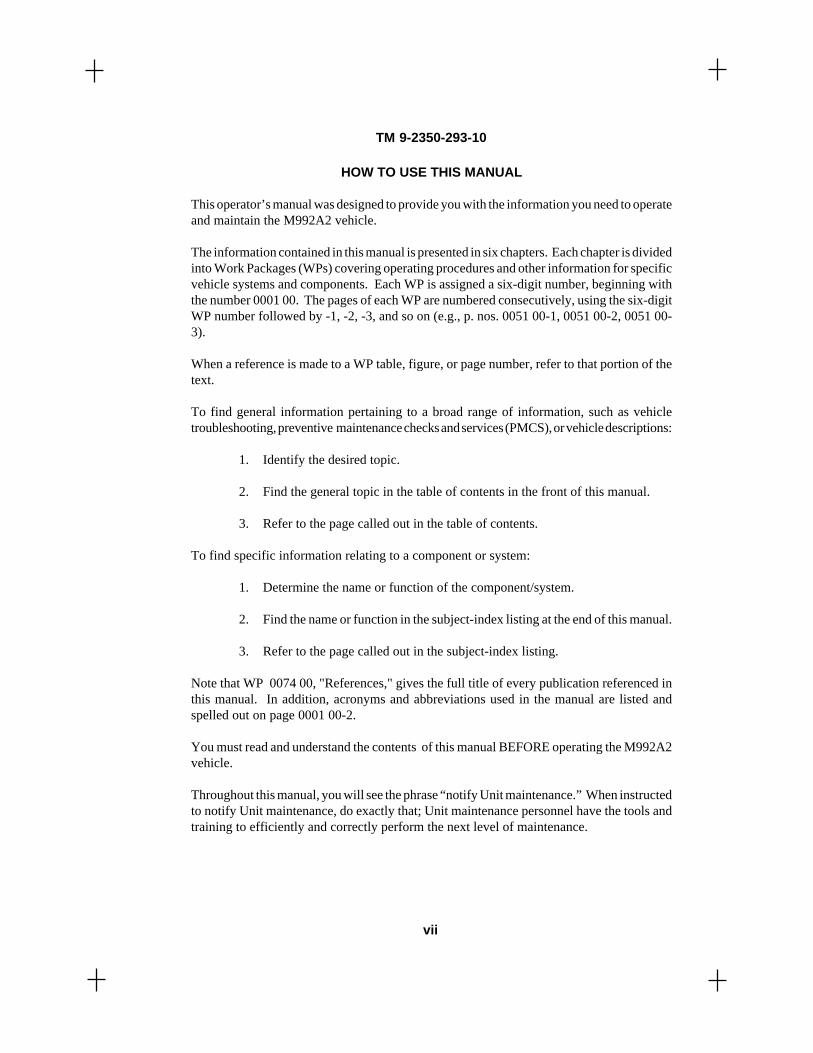
This operator’s manual was designed to provide you with the information you need to operateand maintain the M992A2 vehicle.
The information contained in this manual is presented in six chapters. Each chapter is dividedinto Work Packages (WPs) covering operating procedures and other information for specificvehicle systems and components. Each WP is assigned a six-digit number, beginning withthe number 0001 00. The pages of each WP are numbered consecutively, using the six-digitWP number followed by -1, -2, -3, and so on (e.g., p. nos. 0051 00-1, 0051 00-2, 0051 00-3).
When a reference is made to a WP table, figure, or page number, refer to that portion of thetext.
To find general information pertaining to a broad range of information, such as vehicletroubleshooting, preventive maintenance checks and services (PMCS), or vehicle descriptions:
1. Identify the desired topic.
2. Find the general topic in the table of contents in the front of this manual.
3. Refer to the page called out in the table of contents.
To find specific information relating to a component or system:
1. Determine the name or function of the component/system.
2. Find the name or function in the subject-index listing at the end of this manual.
3. Refer to the page called out in the subject-index listing.
Note that WP 0074 00, "References," gives the full title of every publication referenced inthis manual. In addition, acronyms and abbreviations used in the manual are listed andspelled out on page 0001 00-2.
You must read and understand the contents of this manual BEFORE operating the M992A2vehicle.
Throughout this manual, you will see the phrase “notify Unit maintenance.” When instructedto notify Unit maintenance, do exactly that; Unit maintenance personnel have the tools andtraining to efficiently and correctly perform the next level of maintenance.
TM 9-2350-293-10
vii

HOW TO USE THIS MANUAL (continued)
WARNINGS, CAUTIONS, AND NOTES
Throughout this manual you will see WARNING, CAUTION, and NOTE headings.Warnings and cautions precede the step(s) to which they apply. Notes can precede or followthe step(s) to which they apply. There are good reasons for every one of these notices.
WARNING
A warning is used to alert the user to hazardous operating and maintenanceprocedures, practices, or conditions that could result in injury or death.Warnings must be strictly observed.
CAUTION
A caution is used to alert the user to hazardous operating or maintenanceprocedures, practices, or conditions that could result in damage to, ordestruction of, equipment or mission effectiveness. Cautions must be strictlyobserved.
NOTE
A note highlights an essential operating or maintenance procedure, condition, orstatement.
CHAPTER CONTENTS
Chapter 1, "Description and Theory of Operation," explains the theory of operation forspecific M992A2 vehicle systems, such as the powerpack and auxiliary power unit.
Chapter 2, "Operator Instructions," details how to operate the M992A2 and its subsystems,including a description of operator’s controls and indicators, portable instrument panelcheckout procedure, operation of vehicle lights, hydraulic pump operation, and emergencyprocedures.
Chapter 3, "Troubleshooting Procedures," contain a list of common malfunctions andrecommended tests, inspections, and corrective actions for the M992A2 vehicle. A SymptomIndex is included, to assist in the tracing of common malfunctions.
TM 9-2350-293-10
viii

HOW TO USE THIS MANUAL (continued)
Chapter 4, "Maintenance Instructions," contains the vehicle maintenance procedures thatcrewmembers are authorized to perform, such as engine cooling system maintenance,refueling, and track maintenance. Preventive maintenance checks and services (PMCS) arealso included in this chapter. PMCS refers to the step-by-step care, inspection, and serviceof equipment to maintain it in good condition and to find problems before extensive andtime-consuming repairs or replacements are needed.
Chapter 5, "Automatic Fire Extinguishing System (AFES)," describes the equipment andoutlines the location of components pertaining to the M992A2 vehicle AFES. Also includedare operator’s instructions and emergency procedures.
Chapter 6, "Supporting Information," contains the following supporting information:references, components of end item and basic issue items lists, additional authorization list,expendable and durable items list, and lubrication instructions.
END OF WORK PACKAGE
TM 9-2350-293-10
ix/x blank


GENERAL INFORMATION
TM 9-2350-293-10


SCOPE
This manual contains information you need to operate the M992A2, Tracked AmmunitionCarrier. The primary use of the M992A2 is to provide overland transport of 155-millimeter projectiles and charges from ammunition supply points to howitzers in thefield. Included in the manual are instructions for the proper use of on-board ammunitionhandling and stowage equipment, as well as driving and crew maintenance procedures.
In terms of driving capabilities and limitations, the M992A2 is comparable to the M109A6howitzer. The speed, mobility, and maneuverability of the M992A2 equals that of theM109A6, making the M992A2 well suited for efficient resupply of ammunition to M109A6howitzers.
MAINTENANCE FORMS, RECORDS, AND REPORTS
Department of the Army forms and procedures used for equipment maintenance will be thoseprescribed by DA PAM 738-750, Functional Users Manual for the Army MaintenanceManagement Systems (TAMMS).
REPORTING EQUIPMENT IMPROVEMENT RECOMMENDATIONS (EIR'S)
If your M992A2 needs improvement, let us know. Send us an EIR. You, the user, are the onlyone who can tell us what you don't like about your equipment. Let us know why you don'tlike the design or performance. Put it on an SF 368 (Product Quality Deficiency Report). Mailit to: Commander, U.S. Army Tank-automotive and Armaments Command, ATTN: AMSTA-TR-E/PQDR, Warren, MI 48397-5000.
HAND RECEIPT (HR) MANUAL
This manual has a companion document with a TM (technical manual) number followed by"-HR" (hand receipt). TM 9-2350-293-10-HR consists of preprinted hand receipts that listthe end-item-related equipment that must be accounted for: Components of End Item(COEI), Basic Issue Items (BII), and Additional Authorization List (AAL). As an aid toproperty accountability, additional HR manuals may be requisitioned through normalpublication channels.
OPERATOR'S MANUALCARRIER, AMMUNITION, TRACKED, M992A2
GENERAL INFORMATION
0001 00
0001 00-1
TM 9-2350-293-10

CORROSION PREVENTION AND CONTROL (CPC)
CPC of Army materiel is a continuing concern. It is important that any corrosion problemswith this item be reported so that the problem can be corrected and improvements can be madeto prevent the problem in future items.
While corrosion is typically associated with rusting of metals, it can also include deteriorationof other materials, such as rubber and plastic. Unusual cracking, softening, swelling, orbreaking of these materials may be a corrosion problem.
If a corrosion problem is identified, it can be reported using SF 368, Product QualityDeficiency Report. Use of key words such as "corrosion," "rust," "deterioration," or "cracking"will ensure that the information is identified as a CPC problem.
The form should be submitted to the address specified in DA PAM 738-750, Functional UsersManual for the Army Maintenance Management System (TAMMS).
OZONE DEPLETING SUBSTANCES (ODS'S)
The continued use of ODSs has been prohibited by Executive Order 12856 of 3 August 1993.A listing of these substances will be provided by the acquiring activity.
DESTRUCTION OF ARMY MATERIEL TO PREVENT ENEMY USE
Refer to TM 750-244-6 for procedures on destruction of military vehicles. Destruction ofmunitions is covered in TM 43-0002-33.
PREPARATION OF EQUIPMENT FOR SHIPMENT
Refer to Work Package (WP) 0069 00 for procedures on preparation of the M992A2 forshipment.
LIST OF ABBREVIATIONS AND ACRONYMS
A ............................ annuallyAAL .......................Additional Authorization ListAFES ...................... automatic fire extinguishing systemAFES/MDS ............automatic fire extinguishing system manual discharge systemAHE ....................... ammunition handling equipmentANR .......................Active Noise ReductionAOAP .....................Army Oil Analysis ProgramAPU ........................auxiliary power unit
GENERAL INFORMATION (continued) 0001 00
0001 00-2
TM 9-2350-293-10

LIST OF ABBREVIATIONS AND ACRONYMS (continued)
BE ..........................baleBII ..........................Basic Issue ItemsBIT .........................Built-In TestBITE ......................Built-In Test EquipmentC ............................CelsiusCAGEC ..................Commercial and Government Entity Codecal. .........................caliberCARC ....................chemical agent resistant coatingCK ..........................cyanogen chloridecm ..........................centimeterCN ..........................canCOEI ......................Components of End ItemCOMB. ..................combinationCPC ........................corrosion prevention and controlcu ........................... cubicCVC ....................... combat vehicular crewmanD ............................day, dailyDA ..........................Department of the ArmyDIA ........................diameterDOD .......................Department of DefenseDR ..........................drumE ............................. emptyEA ..........................eache.g. ......................... for exampleEIR .........................Equipment Improvement RecommendationExt. ........................extinguisherF .............................Fahrenheit, fullFAASV ...................Field Artillery Ammunition Support VehicleFFCS ...................... full function crew stationGAA .......................grease, automotive and artillerygal. .........................gallonGL ..........................gallonGPS ........................Global Positioning SystemH ............................hourHD ..........................hundredHR ..........................hand receiptIAW ........................ in accordance withILLUS .................... illustrationin. ........................... inchIR ........................... infraredkg ...........................kilogramkm ..........................kilometer
GENERAL INFORMATION (continued) 0001 00
0001 00-3
TM 9-2350-293-10

LIST OF ABBREVIATIONS AND ACRONYMS (continued)
kph .........................kilometers per hourKT ..........................kitL ............................. liter, lowLAW ...................... lubricating oil for aircraft weaponslb, LB .....................poundLED ........................ light-emitting diodeLG .......................... largeL.H. ........................ left handLHR/CS ................. low heat rejection/cold startLRB ....................... left rear bottom (canister stowage area)LRT ........................ left rear top (canister stowage area)m ............................meterM ...........................monthlymax. .......................maximumMCS .......................Master Control StationMDS .......................manual discharge systemmi ...........................milemm .........................millimeterMOM .....................momentarymph ........................miles per hourMTOE ....................Modification Table of Organization and EquipmentMWRH ..................mounted water ration heaterN ............................neutralNBC .......................nuclear, biological, or chemicalNCO .......................noncommissed officerOC ..........................on conditionODS ........................ozone depleting substanceOFSA .....................Optical Fire Sensing Assemblyoz, OZ ....................ouncep. ............................pagePG ..........................packagePLGR .....................precision lightweight GPS receiverPMCS.....................preventive maintenance checks and servicespp. ..........................pagespsi ..........................pounds per square inchPT...........................pintPTT ........................push-to-talkqt, QT .....................quart
GENERAL INFORMATION (continued) 0001 00
0001 00-4
TM 9-2350-293-10

LIST OF ABBREVIATIONS AND ACRONYMS (continued)
QTY .......................quantityQTY. RECM. ........quantity recommendedQTY. RQR. ............quantity requiredR.H. ........................ right handRL .......................... rollrpm ......................... revolutions per minuteRRB ....................... right rear bottom (canister stowage area)RRM ...................... right rear middle (canister stowage area)RRT ....................... right rear top (canister stowage area)RSI ......................... remote status indicatorS ............................. semiannuallySCEA ..................... standard control electronic amplifierS/N ......................... serial numberSTE/ICE .................simplified test equipment/internal combustion engineT/A ......................... test and alarmTAMMS .................The Army Maintenance Management System3D .......................... three dimensionalTM ......................... technical manualTOE ........................Table of Organization and EquipmentTU .......................... tubeU/M ........................unit of measureV dc ........................Volt, direct currentVFP ........................ventilated face pieceVFPS ......................ventilated face piece systemW/ ..........................withW/O ........................withoutWP .........................Work Package
END OF WORK PACKAGE
GENERAL INFORMATION (continued) 0001 00
0001 00-5/6 blank
TM 9-2350-293-10


CHAPTER 1
DESCRIPTION AND THEORY OF OPERATION
TM 9-2350-293-10


0002 00-1
TM 9-2350-293-10
EQUIPMENT CHARACTERISTICS, CAPABILITIES, AND FEATURES
The M992A2 is a field artillery ammunition support vehicle comparable in speed, mobility,and survivability to current field artillery weapons (M109A6 self-propelled howitzer class).
Capabilities
This full-tracked, self-propelled, diesel-powered vehicle is highly mobile and maneuverable.It is capable of long-range, high-speed operation on improved roads and is well suited torough terrain, muddy or marshy ground, sand, snow, or ice. The M992A2 can also fordwaterways where maximum depth is 42 inches (106.68 cm).
Features
The M992A2 has the following features:
• Ammunition handling equipment (AHE) that includes a hydraulically operated conveyorassembly, two projectile rack assemblies, canister stowage components, and relatedcomponents.
• A diesel-powered auxiliary power unit (APU) used to drive the hydraulic system andrecharge vehicle batteries.
• Simplified test equipment for the internal combustion engine (STE/ICE).
• Automatic fire extinguishing system (AFES).
AFES is an automatic and manual electrical system that, when activated, providesfire-extinguishing capability for the engine and crew compartments. It consists oftest and alarm panels, sensors, and associated equipment explained later in Chapter5.
Automatic electrical operation will automatically sense and discharge an agent toextinguish hydrocarbon fires. The crew system provides an automatic electricalsecond-shot capability if the fire continues burning or if a second fire occurs.
To discharge the fire-extinguishing agent, manual electrical operation must bemanually activated by the crew. The crew system second-shot manual electricalactivation is available if the fire continues to burn; it must be manually activatedby a crew member.
These systems will not activate unless the crew/engine test and alarm panelmaintenance switches are in the horizontal POWER ON normal operational position(see Chapter 5).
0002 00
OPERATOR'S MANUALCARRIER, AMMUNITION, TRACKED, M992A2
EQUIPMENT DESCRIPTION AND DATA

0002 00-2
TM 9-2350-293-10
EQUIPMENT DESCRIPTION AND DATA (continued) 0002 00
Features (continued)
• Nuclear, biological, or chemical (NBC) agent detection and protection system.
• Ammunition storage racks and compartments.
LOCATION AND DESCRIPTION OF MAJOR COMPONENTS
The locations and descriptions of major components used to operate the M992A2 effectivelyare shown on pages 0002 00-2 through 0002 00-6.
MAIN ENGINE EXHAUST OUTLET (1): Provides outlet for main engine exhaust gases.
APU ENGINE EXHAUST OUTLET (2): Provides outlet for APU engine exhaust gases.
IDLER WHEELS (3): Right and left idler wheels guide, support, and maintain tension for thetrack.
ROADWHEELS (4): Seven sets per side provide support and guide the track.
LANYARD CABLE PULL HANDLE (5): Provides for emergency manual discharge of oneengine compartment and two crew compartment fire extinguishers to extinguish fires in theengine and crew compartments.
TRACKS (6): Eighty two-pin, rubber-padded track shoes per side provide support andtraction in various terrains.
DRIVE SPROCKETS (7): Left and right sprockets are mounted on the final drives to driveeach track.
HEADLAMPS (8): Provide light for night driving under normal or blackout conditions.

0002 00-3
TM 9-2350-293-10
EQUIPMENT DESCRIPTION AND DATA (continued) 0002 00
LOCATION AND DESCRIPTION OF MAJOR COMPONENTS (continued)
UPPER REAR DOOR (BALLISTIC SHIELD) (1): Provides ballistic protection to personneland materiel in crew compartment during vehicle operation.
COMMANDER'S CUPOLA (2): Provides access to machine gun mount; rotates manually360 degrees (6400 mils).
MACHINE GUN (3): M2, 0.50-caliber heavy barrel provides protection for the vehicle.
AN/PSN-11 (PLGR) (4): Satellite Signals Navigation Set Antenna, in conjunction withGlobal Positioning System (GPS) unit, provides highly accurate, continuous, all-weather,three-dimensional (3D) position, velocity, and time.
TAILLIGHT/STOPLIGHT (5): Two combination taillight/stoplight units provide rear lightfor night driving under normal and blackout conditions.
M13 DECONTAMINATING APPARATUS, PORTABLE (6): Used to spray decontaminatingagent DS-2 on surfaces of the vehicle and equipment to reduce the level of chemical toxicagents.
DOG DOORS (7): Two dog doors allow operation of conveyor while upper rear door is closed.
REAR NATO SLAVE RECEPTACLE (8): Used to connect the M992A2 electrical systemwith that of another vehicle to provide power access.

0002 00-4
TM 9-2350-293-10
LOCATION AND DESCRIPTION OF MAJOR COMPONENTS (continued)
M992A2 Engine, Transmission, and Driver's Compartments
DRIVER'S CONTROLS AND INDICATORS (1): Contained entirely in the driver'scompartment, they allow driver to operate and monitor vehicle systems.
LANYARD CABLE PULL HANDLE (2): Allows driver to manually discharge one enginecompartment fire extinguisher bottle without leaving the vehicle.
FORWARD NATO SLAVE RECEPTACLE (3): Used to provide power access and connectthe M992A2 electrical system with that of another vehicle for slave-starting operations.
DRIVER'S COOLING FAN (4): Fan helps cool driver during operations in hot weather.
DRIVER'S STEERING CONTROLS (5): Allow driver to control vehicle direction.
UPPER AND LOWER FUEL TANKS (6) (upper tank shown): Store fuel to power the mainengine and the APU.
COOLING FANS AND RADIATOR (7): Provide cooling to main engine.
MAIN ENGINE (8): Diesel, 8V71T, low heat rejection/cold start (LHR/CS) engine providespower to drive transmission.
MAIN ENGINE EXHAUST SYSTEM (9): Expels exhaust gases from main engine.
BATTERIES (10): Four 12-volt lead-acid batteries connect to provide 24-volt vehicleelectrical system.
EQUIPMENT DESCRIPTION AND DATA (continued) 0002 00

0002 00-5
TM 9-2350-293-10
LOCATION AND DESCRIPTION OF MAJOR COMPONENTS (continued)
M992A2 Engine, Transmission, and Driver's Compartments (continued)
FINAL DRIVE ASSEMBLIES (11): Transfer direct drive from transmission to drive sprockets.
TRANSMISSION (12): XTG-411-4 transmission contains cross-drive torque converter andprovides four speeds forward and two reverse.
M992A2 Crew and Cargo Compartment
LEFT REAR CHARGE CANISTER STOWAGE SHELVES (1): Provide stowage for M13A2canisters, PA37A1 canisters, fuses, 0.50-caliber ammunition, primer, and three copperheadrounds.
MOUNTED WATER RATION HEATER (MWRH) (2): Provides ability to heat rations andwater.
LEFT FRONT CHARGE CANISTER STOWAGE AREA (3): Provides stowage for M13A2canisters.
HYDRAULIC CONTROL PANEL (4): Contains controls and gages for operation of hydraulicsystem.
EQUIPMENT DESCRIPTION AND DATA (continued) 0002 00

0002 00-6
TM 9-2350-293-10
LOCATION AND DESCRIPTION OF MAJOR COMPONENTS (continued)
M992A2 Crew and Cargo Compartment (continued)
PROJECTILE RACK ASSEMBLIES (5): Two projectile rack assemblies, each containingfive removable and interlocking rack sections, provide stowage capacity for 90 155-millimeter projectiles. Boxes above the rack assemblies provide stowage for M3A1 canistersand M119A1 canisters.
HYDRAULIC RESERVOIR (6): Contains hydraulic fluid to operate conveyor and upper reardoor.
PERSONNEL HEATER (7): Provides heat in crew compartment.
RIGHT FRONT CHARGE CANISTER STOWAGE SHELVES (8): Provide stowage forM13A2 canisters, PA37A1 canisters, and 0.50-caliber ammunition.
AN/PSN-11 MOUNT ASSEMBLY (9): Provides stowage for AN/PSN-11 (precision lightweightGPS receiver, or PLGR).
RIGHT REAR CHARGE CANISTER STOWAGE SHELVES (10): Provide stowage forM13A2 canisters and PA37A1 canisters.
COMMANDER'S SEAT (11): Provides seating for the commander.
CONVEYOR (12): Used to load or unload ammunition. Conveyor can be operated hydraul-ically or manually.
EQUIPMENT DESCRIPTION AND DATA (continued) 0002 00

0002 00-7
TM 9-2350-293-10
EQUIPMENT DATA
General
Armament .................. 0.50-cal., M2, HB flex machine gun; three 5.56-mm, M16A2 riflesCrew ................................................................................................. During transit—max. 5
During operation—3Engine ............................................................................. 2-cycle, 8V71T diesel (LHR/CS)Brake horsepower (max.) ........................................................................... 405 at 2300 rpmBrake horsepower (continuous) ................................................................ 345 at 2300 rpmBrake horsepower (full load) ..................................................................... 440 at 2300 rpmTransmission ......................................................................................................XTG-411-4
Weight and Dimensions
Combat loaded .................................................................................. 57,500 lb (26,105 kg)Overall length ....................................................................................... 260 in. (660.40 cm)Overall width ........................................................................................ 124 in. (314.96 cm)Width between tracks ............................................................................. 94 in. (238.76 cm)Height (overall; combat loaded to top of GPS antenna assembly) ...... 143 in. (363.22 cm)Ground clearance .......................................................................................15 in. (38.10 cm)Electrical system: Battery power .........................................................................................................24 V dc Batteries ........................................................................................................................... 4
EQUIPMENT DESCRIPTION AND DATA (continued) 0002 00

0002 00-8
TM 9-2350-293-10
EQUIPMENT DATA (continued)
Capacities
Fuel tanks (upper and lower) (diesel) .................................................... 135 gal. (511.03 L)Engine crankcase ............................................................................. 9 1/2 gal. (35.96 L) dry
6 3/4 gal. (25.55 L)Transmission .................................................................................24 1/2 gal. (92.73 L) dry
14 gal. (53 L) refillCooling system ..............................................................................20 1/4 gal. (76.65 L) dry
14 1/2 gal. (54.89 L) refillAPU crankcase (Onan Model DJEAM) ...................................................... 3 1/2 qt (3.31 L)APU crankcase (Hatz Model 2 G 40) ............................................................. 2.65 qt (2.5 L)APU chaincase .................................................................................................. 1 qt (0.95 L)Hydraulic reservoir ........................................................................18 1/2 gal. (70.03 L) dry
13 gal. (49.26 L) refillFinal drive ........................................................................................................ 2 qt (1.89 L)Fan gear case ............................................................................................... 0.43 qt (0.41 L)
Performance
Maximum speed ................................................................................... 35 mph (56.31 kph)Maximum speed, reverse ....................................................................... 7 mph (11.26 kph)Cruising range ..................................................................................... 220 mi (353.98 km)Grade-ascending ability (max.) .......................................................................... 60 percentGrade-descending ability (max.) ........................................................................ 60 percentMaximum trench-crossing width ........................................................... 72 in. (182.88 cm)Maximum vertical wall ............................................................................ 21 in. (53.34 cm)Minimum turning radius ........................................................................... 1 vehicle lengthFording depth ......................................................................................... 42 in. (106.68 cm)
END OF WORK PACKAGE
EQUIPMENT DESCRIPTION AND DATA (continued) 0002 00

MAIN ENGINE: A turbocharged, 2-cycle, V-8 engine provides 440 horsepower at 2300revolutions per minute necessary to drive the vehicle transmission.
TRANSMISSION: Transmission, differential, steering, and braking are combined into oneunit. A cross-drive torque converter transmits torque to final drive assemblies. Thetransmission provides 4-speed forward and 2-speed reverse capability.
END OF WORK PACKAGE
TM 9-2350-293-10
0003 00-1/2 blank
OPERATOR'S MANUALCARRIER, AMMUNITION, TRACKED, M992A2
THEORY OF OPERATION: POWERPACK
0003 00


TM 9-2350-293-10
APU: The APU uses an independent engine to drive (via a chain-and-sprocket arrangement)an electrical generator and hydraulic pump.
ONAN MODEL DJEAM APU ENGINE: The Onan APU engine is a 2-cylinder, 4-cycle,11.5-horsepower diesel engine. Ignition, fuel supply switch, and engine indicators arelocated on the APU control box in the cargo compartment.
HATZ MODEL 2 G 40 APU ENGINE: The Hatz APU engine is a 2-cylinder, 4-cycle, 13.5-horsepower diesel engine. Ignition, fuel supply switch, and engine indicators are located onthe APU control box in the cargo compartment.
ELECTRICAL GENERATOR: The generator supplies enough power to run its ownelectrical system and that of a supported vehicle, via slave receptacles and cable. This slavepower may be used to charge dead batteries of a disabled vehicle or to operate the supportedvehicle's electrical system.
HYDRAULIC PUMP: The rotary-gear-type hydraulic pump supplies hydraulic fluid to allhydraulic circuits whenever the APU is functioning.
END OF WORK PACKAGE0004 00-1/2 blank
OPERATOR'S MANUALCARRIER, AMMUNITION, TRACKED, M992A2
THEORY OF OPERATION: AUXILIARY POWER UNIT (APU)
0004 00


TM 9-2350-293-10
HYDRAULIC RESERVOIR: Holds hydraulic system fluid. Reservoir capacity is 13gallons (49.26 L).
SUCTION LINE: Passes fluid to the hydraulic pump. A strainer at the inlet of the lineprevents contaminants from entering the hydraulic circuits.
RETURN LINE: Passes exhausted hydraulic fluid back to the reservoir. An in-line, 10-micron filter removes particles from the returning fluid.
FILL CAP AND TUBE: Permit ease of hydraulic fluid refill. A strainer is housed withinthe tube to prevent entry of contaminants.
FLUID LEVEL TRANSMITTER: Monitors the level of hydraulic fluid in the reservoir.The transmitter emits an electronic signal to a level gage on the hydraulic control panel.
FLUID TEMPERATURE TRANSMITTER: Monitors the temperature of hydraulic fluid inthe reservoir. The transmitter emits an electronic signal to a temperature gage on thehydraulic control panel.
MICRON FILTER (HIDDEN): Filters hydraulic fluid returning to the reservoir.
END OF WORK PACKAGE
0005 00-1/2 blank
OPERATOR'S MANUALCARRIER, AMMUNITION, TRACKED, M992A2
THEORY OF OPERATION: HYDRAULIC RESERVOIR
0005 00


TM 9-2350-293-10
M2A2 AIR PURIFIER UNIT: Removes all known chemical agents from the air. The air purifiercan produce a flow of 12 cubic feet (0.34 cu m) of breathable air per minute. The pure air issupplied to up to four crew members through hosing to four air outlet orifices and individualM25A1 face pieces. The air purifier unit consists of an M13 particulate filter, an M12A1 gasfilter, and an M1A1 air purifier precleaner in a steel housing.
AIR OUTLET ORIFICES: Provide stowage locations for hoses that connect to canisters onM25A1 face pieces. Three orifices are located in the crew compartment, and one is locatedin the driver's compartment.
NUCLEAR, BIOLOGICAL, OR CHEMICAL (NBC) POWER CONTROL BOX: ContainsON/OFF switch for operation of the VFPS.
M3 HEATERS: Warm the air before it reaches the face pieces. A heater is connected in-lineto each M25A1 face piece. Each heater is individually temperature adjusted and operated.Heaters must be turned on when operating the VFPS in outside temperatures of less than 40°F(4.4°C).
END OF WORK PACKAGE
0006 00-1/2 blank
OPERATOR'S MANUALCARRIER, AMMUNITION, TRACKED, M992A2
THEORY OF OPERATION: VENTILATED FACE PIECE SYSTEM (VFPS)
0006 00


TM 9-2350-293-10
0007 00-1
UPPER REAR DOOR CYLINDER ASSEMBLY: Opens and closes the upper rear door(ballistic shield) hydraulically.
FLOW-CONTROL VALVE: An adjustable valve that enables smooth closing of the upperrear door (ballistic shield). This valve is preset at the factory and should not requireadjustment.
PILOT CHECK VALVE: Prevents dangerous door drop if hydraulic line ruptures.
DUMP VALVE: Enables the operator to close the door if hydraulic power is lost. This isaccomplished by opening the dump valve and then shifting ballistic shield directional controlvalve, located on the hydraulic control panel, to the down position.
0007 00
OPERATOR'S MANUALCARRIER, AMMUNITION, TRACKED, M992A2
THEORY OF OPERATION: HYDRAULIC ACTUATORS ANDRELATED COMPONENTS

TM 9-2350-293-10
0007 00-2
CONVEYOR MOTOR: Drives the conveyor sprocket and chain. The motor is hydraulicallyoperated and operation is reversible. Rotational direction of the motor is determined by theconveyor directional control valve (p. 0010 00-13). Rotational speed of the motor iscontrolled by the setting of a flow-control valve (p. 0010 00-9).
END OF WORK PACKAGE
THEORY OF OPERATION: HYDRAULIC ACTUATORS ANDRELATED COMPONENTS (continued) 0007 00

TM 9-2350-293-10
M43 CHEMICAL AGENT DETECTOR: Senses the presence of very low concentrations ofchemical agents and breathable aerosols. When contaminants are sensed by the detector, anelectrical signal is sent to the chemical agent alarm. The detector unit may be operated usingpower from the vehicle's electrical system, and it also may be battery operated.
M42 CHEMICAL AGENT ALARM: Signals to crew members that chemical agents havebeen sensed by the M43 detector. The alarm provides an audible and visual signal or a visualsignal only, depending on setting.
END OF WORK PACKAGE
0008 00-1/2 blank
OPERATOR'S MANUALCARRIER, AMMUNITION, TRACKED, M992A2
THEORY OF OPERATION: CHEMICAL AGENT DETECTION ANDALARM SYSTEM THEORY OF OPERATION 0008 00
0008 00


HYDRAULIC CONTROL PANEL/HYDRAULIC MANIFOLD: Controls hydraulic systemfunctions and allows monitoring of hydraulic system pressure.
MAIN RELIEF VALVE: Limits hydraulic system pressure. Normal maximum pressuresetting is 1550 psi (10,686.75 kPa). System pressure over 1550 psi is relieved through thevalve to the reservoir.
OPERATOR'S MANUALCARRIER, AMMUNITION, TRACKED, M992A2
THEORY OF OPERATION: HYDRAULIC CONTROL PANEL
0009 00-1
TM 9-2350-293-10 0009 00

SYSTEM PRESSURE GAGE: Monitors hydraulic system pressure.
FLOW-CONTROL VALVE: Regulates flow of hydraulic fluid. Valve can be adjustedmanually to achieve desired conveyor speed.
CONVEYOR DIRECTIONAL CONTROL VALVE: Controls direction of fluid flow to theconveyor motor. Positioning of an internal spool determines the direction of conveyormotor rotation. The valve may be electrically powered by the conveyor switch or manuallyoperated by pressing the buttons at either side of the valve.
THEORY OF OPERATION: HYDRAULICCONTROL PANEL (continued) 0009 00
0009 00-2
TM 9-2350-293-10

THEORY OF OPERATION: HYDRAULICCONTROL PANEL (continued) 0009 00
BALLISTIC SHIELD DIRECTIONAL CONTROL VALVE: Controls direction of fluid flowto the upper rear door cylinder. Positioning of an internal spool determines direction ofcylinder rod movement. The valve may be electrically powered by either of the upper reardoor switches or may be manually operated by pressing the buttons at either side of thevalve.
TEMPERATURE GAGE: Displays the temperature of hydraulic system fluid monitoredby the fluid temperature transmitter.
LEVEL GAGE: Displays level of hydraulic system fluid in the hydraulic reservoir asmonitored by the fluid level transmitter.
CONVEYOR CONTROL SWITCH: Controls electrical activation of the conveyor directionalcontrol valve.
END OF WORK PACKAGE0009 00-3/4 blank
TM 9-2350-293-10


CHAPTER 2
OPERATOR INSTRUCTIONS
TM 9-2350-293-10


TM 9-2350-293-10
DRIVER'S CONTROLS AND INDICATORS
NOTE
Detailed information for use of the controls and indicators can befound in Work Packages 0011 00 through 0044 00.
OPERATOR'S MANUALCARRIER, AMMUNITION, TRACKED, M992A2
DESCRIPTION AND USE OF OPERATOR CONTROLSAND INDICATORS
THIS WORK PACKAGE COVERS:Driver's Controls and Indicators, Crew Controls and Indicators, andPowerpack
0010 00
0010 00-1

TM 9-2350-293-10
DESCRIPTION AND USE OF OPERATOR CONTROLSAND INDICATORS (continued) 0010 00
DRIVER'S CONTROLS AND INDICATORS (continued)
Security Lock
Prevents intrusion from outside.
A pivoting plate is positioned toengage metal hatch-mountedbracket.
Pivoting the lock handle forwardlocks the hatch; pivoting rearwardreleases the security lock.
0010 00-2

TM 9-2350-293-10
0010 00-3
1 WATER TEMP Gage Indicates temperature of main engine coolant.
2 ENGINE OIL PRESSURE Indicates pressure of main engine oil.Gage
3 FUEL Level Gage Indicates amount of fuel in either upper orlower tank.
4 BATTERY Gage Indicates charge level of batteries.
5 MASTER Switch Controls all vehicle electrical power.
6 TRANSMISSION OIL Indicates pressure of transmission oil.PRESSURE Gage
7 MASTER Power Indicates when MASTER switch is on.Indicator
8 COOLANT Level Indicator Indicates low engine coolant level.
9 TRANSMISSION OIL Indicates temperature of transmission oil.TEMP Gage
REFERENCENO.
CONTROL OR INDICATOR FUNCTION
DESCRIPTION AND USE OF OPERATOR CONTROLSAND INDICATORS (continued) 0010 00
DRIVER'S CONTROLS AND INDICATORS (continued)
Driver's PortableInstrument Panel
Provides personnel with ability to monitormain engine functions while outsidedriver's compartment.
To remove panel, pull free of driver'sinstrument panel and slide into mountingbracket outside driver's compartment.

TM 9-2350-293-10
DESCRIPTION AND USE OF OPERATOR CONTROLSAND INDICATORS (continued) 0010 00
DRIVER'S CONTROLS AND INDICATORS (continued)
1 Tachometer/Hour Meter Indicates engine speed in revolutions perminute and hours of operation.
2 AUXILIARY OUTLET Provides power for auxiliary 24-volt tools.
3 Speedometer/Odometer Indicates vehicle speed in miles per hourand miles traveled.
4 FUEL PRIME Switch Controls fuel pump to prime system.
5 HI-BEAM Indicator Indicates when headlight high beams are on.
6 PARKING BRAKE Indicator Indicates parking brake is engaged.
7 Service Light Switch Controls vehicle lights.
8 UPPER/LOWER FUEL Allows operator to check level in upper andGAGE Switch lower fuel tanks.
9 BILGE PUMP Switch Controls operation of bilge pump.
10 STARTER Switch Controls operation of main engine starter.
11 GLOW PLUG Switch Controls operation of glow plug.
12 GLOW PLUG Indicator Indicates when glow plug system has beenactivated.
REFERENCENO.
CONTROL OR INDICATOR FUNCTION
MAIN Instrument Panel
Allows driver to monitor enginefunctions while operating vehicle.
0010 00-4

TM 9-2350-293-10
The accessory control box controls heat and ventilation of the crew compartment and resetfor the APU and heater.
The HEATER/APU RESET switch (1) resets the APU and heater when the AFES isactivated.
The VENTILATOR RESET switch (2) is for resetting the ventilator when crew AFES isactivated.
Outside air can be drawn into the crew compartment by selecting INTAKE on theVENTILATOR BLOWER control (3). Fumes can be removed from the crew compartmentarea by selecting the EXHAUST setting.
The HEAT SELECTOR switch (4) allows the driver to choose either low or high heat.
An indicator light (5) comes on when the heater is operating.
The HEATER CONTROL switch (6) starts and runs the heater.
For operating instructions for the personnel heater, see page 0033 00-2.
DESCRIPTION AND USE OF OPERATOR CONTROLSAND INDICATORS (continued) 0010 00
DRIVER'S CONTROLS AND INDICATORS (continued)
Accessory Control Box
0010 00-5

TM 9-2350-293-10
Driver's Hold-Open Latch
Holds hatch door open for entry, exit, or drivingwith the seat raised.
Spring-loaded lockpin automatically engages whendoor is fully raised.
Quick-release pin provides driver with protectionfrom falling hatch door should spring-loaded lockpinfail.
To release latch, remove quick-release pin fromhorizontal position and stow in forward hole, thenpull latch knob outward.
Commander's CupolaHold-Open Latch
Holds commander's cupola hatch door open whencommander is observing ammunition loading orunloading or is operating the 0.50-caliber machinegun.
Spring-loaded latch automatically engages whenhatch door is open 120 degrees.
Quick-release pin provides commander withprotection from falling hatch during operation.
To release latch, remove quick-release pin fromhorizontal position and stow in forward hole, thenpush latch handle to release latch.
CREW CONTROLS AND INDICATORS
DESCRIPTION AND USE OF OPERATOR CONTROLSAND INDICATORS (continued) 0010 00
DRIVER'S CONTROLS AND INDICATORS (continued)
0010 00-6

TM 9-2350-293-10
FUEL SHUT OFF Switch
This two-position toggle switch controls electricalpower to the APU fuel solenoid and APU fuelpumps.
When the toggle switch and vehicle MASTERswitch are turned to ON, fuel is supplied for operationof the APU. When the switch is positioned to OFF,fuel supply is shut off.
The switch should always be turned to OFF whenthe APU is shut down.
PREHEAT Switch
Positioning this switch lever to MOM ON turns onthe preheating units in the APU combustion chamberand supplies power to the START switch.
When the switch lever is released, the switchreturns to OFF, the preheating units turn off, andelectrical continuity to the START switch is broken.
START Switch
With the PREHEAT switch held to ON, positioningthe START switch to MOM ON will supply electricalpower to APU starting components.
When the switch lever is released, the switchreturns to OFF and electrical continuity to APUstarting components is broken.
DESCRIPTION AND USE OF OPERATOR CONTROLSAND INDICATORS (continued) 0010 00
CREW CONTROLS AND INDICATORS (continued)
Auxiliary Power Unit (APU) Control Box
APU GEN Switch
This two-position toggle switch turns APUgenerator on and off.
Switch must be set to OFF when startingthe APU.
0010 00-7

TM 9-2350-293-10
DESCRIPTION AND USE OF OPERATOR CONTROLSAND INDICATORS (continued) 0010 00
CREW CONTROLS AND INDICATORS (continued)
Auxiliary Power Unit (APU) Control Box (continued)
ENGINE OIL PRESSURE Gage
Monitors APU engine oil pressure in pounds persquare inch (psi). The gage is graduated in 10 psiincrements from 0 to 60 psi (Onan DJEAM) or 0 to 120psi (Hatz 2 G 40). Normal operating pressure is over25 psi for both Onan DJEAM and Hatz 2 G 40.
LOW OIL PRESS Lamp
This red lamp lights when a low oilpressure condition exists in the APUlubricating system.
HIGH AIR TEMP Lamp
This red lamp lights when the APU overheats.
0010 00-8

TM 9-2350-293-10
Hydraulic Preesure Gage
The gage measures pressure generated by themain hydraulic pump in pounds per square inch(psi), from 0 to 3000 psi.
Gage should measure 100 to 300 psi withhydraulic pump operating conveyor, upper reardoor down, and hydraulic fluid at normaloperating temperature.
Flow-Control Valve
Meters flow of hydraulic fluid to conveyor.
Valve can be manually adjusted to increase ordecrease flow and, therefore, the operatingspeed of conveyor.
HYDRAULIC RESERVOIRTEMPERATURE Gage
Monitors temperature of hydraulic fluid in thereservoir. Temperature is measured in degreesFahrenheit.
Gage is graduated in 20°F increments from120°F to 240°F.
Hydraulic fluid temperature should not exceed160°F.
VEHICLES S/N 1 THROUGH 820
DESCRIPTION AND USE OF OPERATOR CONTROLSAND INDICATORS (continued) 0010 00
CREW CONTROLS AND INDICATORS (continued)
Hydraulic Control Panel
0010 00-9

TM 9-2350-293-10
HYDRAULIC RESERVOIRTEMPERATURE Gage
HydraulicPressure Gage
Flow-ControlValve
VEHICLES S/N 821 AND ABOVE
DESCRIPTION AND USE OF OPERATOR CONTROLSAND INDICATORS (continued) 0010 00
CREW CONTROLS AND INDICATORS (continued)
Hydraulic Control Panel (continued)
0010 00-10

TM 9-2350-293-10
VEHICLES S/N 1 THROUGH 820
CONVEYOR Switch
Electrically controls operation of conveyordirectional control valve.
The three-position switch is positioned down (IN)to load cargo. Upward positioning of switch(OUT) is used to unload cargo. Switch in centerposition stops conveyor.
HYDRAULIC RESERVOIR LEVEL Gage
Monitors hydraulic reservoir fluid level.
Gage is graduated from empty (E) to full (F) in1/4-tank increments.
Fluid should not measure less than 3/4.
DESCRIPTION AND USE OF OPERATOR CONTROLSAND INDICATORS (continued) 0010 00
CREW CONTROLS AND INDICATORS (continued)
Hydraulic Control Panel (continued)
0010 00-11

TM 9-2350-293-10
CONVEYOR Switch
HYDRAULIC RESERVOIR LEVELGage
VEHICLES S/N 821 AND ABOVE
DESCRIPTION AND USE OF OPERATOR CONTROLSAND INDICATORS (continued) 0010 00
CREW CONTROLS AND INDICATORS (continued)
Hydraulic Control Panel (continued)
0010 00-12

TM 9-2350-293-10
BALLISTIC SHIELD DirectionalControl Valve
Directs flow of hydraulic fluid to upper rear door(ballistic shield) actuator.
The valve may be electrically controlled by top orbottom upper rear door switch or manuallyoperated at valve.
For manual operation, press right-hand button toclose upper rear door and press left-hand buttonto open door.
CONVEYOR DirectionalControl Valve
Directs flow of hydraulic fluid to the conveyormotor.
The valve may be electrically controlled by theconveyor switch or manually operated at thevalve.
For manual operation, press the right-hand buttonto move the conveyor chain out; press the left-hand button to move the conveyor chain in.
VEHICLES S/N 1 THROUGH 820
DESCRIPTION AND USE OF OPERATOR CONTROLSAND INDICATORS (continued) 0010 00
CREW CONTROLS AND INDICATORS (continued)
Hydraulic Control Panel (continued)
0010 00-13

TM 9-2350-293-10
VEHICLES S/N 821 AND ABOVE
BALLISTIC SHIELDDirectional
Control Valve
CONVEYOR DirectionalControl Valve
DESCRIPTION AND USE OF OPERATOR CONTROLSAND INDICATORS (continued) 0010 00
CREW CONTROLS AND INDICATORS (continued)
Hydraulic Control Panel (continued)
0010 00-14

TM 9-2350-293-10
Upper Rear DoorSwitch–Top
This three-position, momentary-contactswitch controls electrical power formovement of the upper rear door.
When switch is positioned to UP, thedoor opens. When switch is positionedto DOWN, the door closes.
When switch lever is released, it returnsto center (off) position and upper reardoor movement stops.
Upper Rear DoorMechanical Lock
Mechanically secures upper rear doorin open position.
The mechanical lock holds door open in45-degree or 90-degree position bywedging between door and roof plate.
When door opens, lock latchesautomatically.
DESCRIPTION AND USE OF OPERATOR CONTROLSAND INDICATORS (continued) 0010 00
CREW CONTROLS AND INDICATORS (continued)
Upper Rear Door (Ballistic Shield)
0010 00-15

TM 9-2350-293-10
Upper Rear DoorSwitch–Bottom
This switch is identical to switch at top andis operated the same way.
The bottom switch is positioned just insideleft side of lower rear door, well within reachof personnel outside vehicle.
Upper Rear DoorDump Valve
The valve is used to permit opening andclosing of the door if hydraulic system fails.
Opening the valve allows hydraulic fluid tobypass flow-restrictive devices in circuit.
The valve should be used to open or closedoor manually only in emergencies.
DESCRIPTION AND USE OF OPERATOR CONTROLSAND INDICATORS (continued) 0010 00
CREW CONTROLS AND INDICATORS (continued)
Upper Rear Door (Ballistic Shield) (continued)
0010 00-16

TM 9-2350-293-10
ConveyorDeadman
Switch
ConveyorOverride Safety
Switch
Conveyor Override Safety Switch
This two-position toggle switch is used to turn off conveyor from outside end ofconveyor. It does this by breaking electrical continuity through the conveyorcircuit, overriding main CONVEYOR switch on hydraulic control panel. Thesafety switch should be turned off each time conveyor is stowed.
Turning override safety switch to OFF shuts down conveyor. With safety switchturned to ON and main CONVEYOR switch positioned to either IN or OUT,conveyor will operate in selected direction.
This switch is only one safety device used to prevent pile-up of ammunition onconveyor. The main CONVEYOR switch and the deadman switch (p. 0030 00-11) should be used for normal operation.
DESCRIPTION AND USE OF OPERATOR CONTROLSAND INDICATORS (continued) 0010 00
CREW CONTROLS AND INDICATORS (continued)
Conveyor
0010 00-17

TM 9-2350-293-10
ManualOperatingCrank
Manual Operating Crank
The crank is used to operate the conveyor when related hydraulic componentsfail.
When needed, crank handle is removed from its stowage location at base of leftrear canister compartment and is inserted into hole opposite hydraulic motor.
Turning handle clockwise moves conveyor chain out. Turning handlecounterclockwise moves conveyor chain in.
DESCRIPTION AND USE OF OPERATOR CONTROLSAND INDICATORS (continued) 0010 00
CREW CONTROLS AND INDICATORS (continued)
Conveyor (continued)
0010 00-18

TM 9-2350-293-10
Chemical Agent Detector M43
Detects very low concentrations of chemicalagent vapors and inhalable aerosols. Detectormay be operated continuously but must beserviced every 12 hours.
Refer to TM 3-6665-225-12 for detaileddescription of this unit.
Chemical Agent Alarm M42
When connected to M43 detector, M42 alarmprovides remote audible and/or visual signalif M43 detector senses a chemical agent.
For a detailed description of this unit, refer toTM 3-6665-225-12.
DESCRIPTION AND USE OF OPERATOR CONTROLSAND INDICATORS (continued) 0010 00
CREW CONTROLS AND INDICATORS (continued)
Chemical Agent Detection and Alarm System
0010 00-19

TM 9-2350-293-10
M3 HeaterIndicator Lamp
When a heater is turned on,its blue-green lamp will light.
Air Purifier Control BoxPower Indicator Lamp
This blue-green lamp lights when on/offswitch is turned to ON.
Air Purifier ControlBox On/Off Switch
When turned to ON, this switch activatesair purifier unit and supplies electricalpower for operation of M3 heaters.
This switch is a two-position toggle switchcovered by a red guard.
The switch lever is positioned up for ONand down for OFF.
M3 Heater Control Knob
When turned, the knob controls warmingof breathable, filtered air received ateach ventilated face piece (VFP).
When NBC power control box on/offswitch is set to ON, control knob at eachheater can be turned on and adjusted fordesired heater.
Turning control knob clockwise increasesheat. Each heater is individuallycontrolled.
DESCRIPTION AND USE OF OPERATOR CONTROLSAND INDICATORS (continued) 0010 00
CREW CONTROLS AND INDICATORS (continued)
Ventilated Face Piece System (VFPS)
0010 00-20

TM 9-2350-293-10
DESCRIPTION AND USE OF OPERATOR CONTROLSAND INDICATORS (continued) 0010 00
CREW CONTROLS AND INDICATORS (continued)
Intercommunications Equipment AN/VIC-3(V)
CD-82/VRC
This is the master control station for the AN/VIC-3(V) intercommunication system.Unit must be properly set up for intercommunications system to work.
Refer to TM 11-5830-263-10 for a detailed description of this unit.
C-12357/VRC
This is the individual control box for each crew member using an audio accessory.The audio accessory connects with intercommunications system via receptacles atbase of C-12357/VRC.
Refer to TM 11-5830-263-10 for a detailed description of this unit.
0010 00-21

TM 9-2350-293-10
Dome Lights
Five dome lights provide lighting for interiorof cargo compartment.
Each unit is individually switched on and off.
Turning knob fully clockwise turns on whitelight. To turn on blue-green light, presssafety switch and turn knob counterclockwisepast stop. To turn light off, turn knob tocenter position.
Air CleanerRestriction Indicator
Indicates a restricted or blocked filter.
Signal window displays a yellow sleevethat indicates amount of restriction in aircleaner. When sleeve climbs into redzone, air cleaner filter is restricted andrequires service.
DESCRIPTION AND USE OF OPERATOR CONTROLSAND INDICATORS (continued) 0010 00
CREW CONTROLS AND INDICATORS (continued)
Miscellaneous Controls and Indicators
0010 00-22

TM 9-2350-293-10
APU Hour Meter
Located in APU compartment, the hourmeter measures hours of APU operationin 1/10-hour increments.
APU Generator Air Filters
Filters and precleans air intake intoAPU generator.
ONAN DJEAM
HATZ 2 G 40
APU Hour Meter
APU GeneratorAir Filters
DESCRIPTION AND USE OF OPERATOR CONTROLSAND INDICATORS (continued) 0010 00
CREW CONTROLS AND INDICATORS (continued)
Miscellaneous Controls and Indicators (continued)
0010 00-23
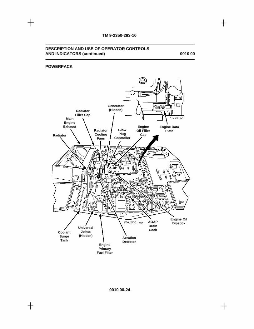
TM 9-2350-293-10
DESCRIPTION AND USE OF OPERATOR CONTROLSAND INDICATORS (continued) 0010 00
POWERPACK
Generator(Hidden)
MainEngineExhaust
Radiator
AerationDetector
AOAPDrainCock
EngineOil Filler
CapGlowPlug
Controller
Engine OilDipstick
Engine DataPlate
CoolantSurgeTank
EnginePrimary
Fuel Filter
UniversalJoints
(Hidden)
RadiatorFiller Cap
RadiatorCooling
Fans
0010 00-24

TM 9-2350-293-10
DESCRIPTION AND USE OF OPERATOR CONTROLSAND INDICATORS (continued) 0010 00
TransmissionThrottle
Valve RodV-8 Diesel
Engine 8V71T(LHR/CS)
TurbochargerAir Outlet
Fuel SystemAir Purge
Pump Assembly
Fuel ShutoffCable
TransmissionFiller Cap and
Gage Rod
Engine OilFilters
Transmission–XTG411-4
Transmission ShiftControl Rod
Transmission Steer Control Rod
EngineSecondaryFuel Filter
END OF WORK PACKAGE
0010 00-25/26 blank
POWERPACK (continued)

TM 9-2350-293-10

TM 9-2350-293-10
ASSEMBLY AND PREPARATION FOR USE
Before operating a new or reconditioned vehicle, make sure Unit maintenance services thevehicle.
INITIAL ADJUSTMENT AND DAILY CHECKS
Perform the preventive maintenance checks and services (PMCS) in work packages (WPs)0048 00 through 0051 00 to make sure all adjustments and checks are completed.
OPERATING PROCEDURES
Be familiar with all controls, instruments, and procedures before attempting to operate thevehicle.
WARNING
• Fasten the seatbelt. Drive carefully. Take it easy until you canoperate with skill.
• If a track is thrown while vehicle is moving, do not apply the brake;rather, allow vehicle to coast to a halt.
• Do not move vehicle until all latches and doors are secured in closedposition and all equipment is properly stowed.
• High-intensity noise, hearing protection required. Hearing can bePERMANENTLY DAMAGED if a person is exposed to constant highnoise levels of 85 decibels or greater.
• During operation of main engine or auxiliary power unit (APU),decibel levels exceed safe levels for human hearing. Wear approvedhearing protection devices when working in high noise level areas.Failure to do so could result in injury to personnel.
• Personnel within 38 yards (35 m) of the machine gun must wearapproved single hearing protection (e.g., earplugs) when the machinegun is being fired. Failure to do so could result in injury to personnel.
0011 00-1
OPERATOR'S MANUALCARRIER, AMMUNITION, TRACKED, M992A2
OPERATION UNDER USUAL CONDITIONS
0011 00

TM 9-2350-293-10
OPERATION UNDER USUAL CONDITIONS (continued) 0011 00
• Personnel within 689 yards (630 m) of the howitzers must wearapproved hearing protection during firing. Follow the hearingprotection warnings and obey the hazard zones identified in TM 9-2350-314-10. Failure to do so could result in injury to personnel.
• Personnel within nine yards (8 m) of the vehicle must wear approvedsingle hearing protection when the main engine or APU is running.Failure to do so could result in injury to personnel.
• Operation of the vehicle is limited to 68 miles (110 km) per 24-hourperiod for crews wearing the H-374 [AN/VIC-3(V)] combat vehicularcrewman (CVC) helmet with the Active Noise Reduction (ANR) on.Operation is limited to 13 km per 24-hour period for crews wearing theH-374 [AN/VIC-3(V)] CVC with the ANR off. If the mission exceeds therecommended distances for a 24-hour period, double hearing protection(e.g., earplugs and CVC) must be worn. Failure to do so could resultin injury to personnel.
CAUTION
• Never leave vehicle unattended while engine is running.
• This vehicle does not have an automatic transmission. It must beshifted manually.
• To prevent overheating and damage to transmission and engine,observe the following precautions:
– When starting from a halt, begin with transmission selector leverin first gear.
– Do not hold vehicle on an incline with transmission in gear.
– Prior to shutting down engine, set hand throttle at 1000-1200revolutions per minute for three to five minutes or until coolanttemperature measures 185°F or lower. Then run at idle for one tothree minutes.
– Do not block engine air intake grille with camouflage or othermaterials.
– Do not operate engine at idle for more than 10 minutes. Using handthrottle at fast idle setting (1000 rpm) will help reduce engineoverheating.
END OF WORK PACKAGE
0011 00-2

TM 9-2350-293-10
0012 00-1
WARNING
Whenever vehicle is operated with hatch door opened, hatch doormust be locked.
OPERATOR'S MANUALCARRIER, AMMUNITION, TRACKED, M992A2
STARTING MAIN ENGINE
INITIAL SETUP:Maintenance Level
Operator
0012 00
1. Make sure driver's hatch door will lock in openedand closed positions. Lock driver's hatch doorin desired position.
• Lock opened. Engage hold-open lock (1)with latching pin positioned over flat portionof hatch cover locking tab. Remove quick-release pin (2) from stowage position, andinsert pin (2) through horizontal bracket (3)and over flat portion of hatch door lockingtab.
• Lock closed. With hatch door closed, turnlocking handle (5) to the rear to lock externalhatch door latch (4).
• Security lock. To prevent entry fromoutside, push security latch handle (6)forward.

TM 9-2350-293-10
0012 00-2
2. Adjust driver's seat as necessary.
• Adjusting up and down. Hold seat downand pull up on adjusting lever (7). Withlever raised, lift or press seat to obtaincorrect height. Release adjusting leverto lock in position.
• Adjusting forward and backward. Pullup on adjusting tab (8) and move seatforward or backward. Releaseadjusting tab to lock in position.
• Backrest positioning. Press pawl (9)and rotate backrest up and back. Whenbackrest is positioned vertically,reposition pawl to lock backrest.
• Adjusting backrest height. Removeadjusting pin (10) and lower or raisebackrest. When desired height isobtained, install pin in adjusting holes.
3. Adjust steering wheel by pressing sleevebearing (11) forward and rotating steeringwheel up or down. Raise wheel if drivingwith hatch open; lower wheel when drivingwith hatch closed. When correctadjustment is obtained, release sleevebearing to lock position.
STARTING MAIN ENGINE (continued) 0012 00

TM 9-2350-293-10
0012 00-3
4. If driving in raised position, clip portableinstrument panel (12) into bracket (on topof hull just left of driver's hatch door).
NOTE
• Use the following procedure for starting engine in normal-temperature climates (+40°F, or 4.4°C). Refer to cold-weatherstarting procedures (p. 0037 00-1) when temperature is below+40°F (4.4°C), or if engine will not start in moderately coldclimates.
• Before applying the service brake pedal while on steepslopes (greater than 20 percent), adjust the driver's seat soyou can apply maximum leverage to the brake pedal.
5. Set parking brake by pressing on service brake pedal (15) and pulling out and down onparking BRAKE LOCK handle (13). Parking brake will be set when handle is releasedin this position. If stopping on a steep slope, press on service brake pedal (15), pull outand down on parking BRAKE LOCK handle (13), release, and press on service brakepedal (15) again.
6. Shift transmission selector lever (14) to N (neutral), and make sure it locks into position.
STARTING MAIN ENGINE (continued) 0012 00

TM 9-2350-293-10
0012 00-4
CAUTION
Before starting engine, you should check for hydrostatic lock.Intermittently actuate STARTER switch (with MASTER switch set to ONand FUEL SHUT OFF handle pulled out). The following symptomsindicate hydrostatic lock:
• Engine starts to turn over with starter, then stops.
• Starter sounds as if straining when engine is cranking.
• Engine seems to bind.
If you suspect hydrostatic lock, stop cranking immediately and notifyUnit maintenance.
7. Turn MASTER switch (17) to ON. Indicator lamp (16) and MASTER power light(18) should light with MASTER switch (17) set to ON.
STARTING MAIN ENGINE (continued) 0012 00

TM 9-2350-293-10
0012 00-5
8. Pull FUEL SHUT OFF handle (19) toOFF position before checking forhydrostatic lock.
9. Check for hydrostat ic lock byintermittently activating STARTERswitch (22) (with MASTER switch[17] set to ON and FUEL SHUTOFF handle [19] pulled out).
10. Release FUEL SHUT OFF handle(19).
11. Place throttle control lever (20) inidle position.
12. If fuel filters have been drained sincelast start, hold FUEL PRIME switch(21) to ON for one minute, thenrelease switch.
WARNING
Protect your hearing. Due tohigh-intensity noise, hearingprotection is required whenoperating this vehicle.
CAUTION
Do not operate starter con-tinuously for over 30 seconds.If engine does not start, allowone-minute cool-off periodbefore engaging starter again.Notify Unit maintenance ifengine fails to start after fourthtry.
STARTING MAIN ENGINE (continued) 0012 00

TM 9-2350-293-10
0012 00-6
NOTE
An electrical relay prevents driver from operating startercontinuously for more than 30 seconds. If tactical situationdictates, commander can use combat starter override switch(p. 0044 00-8) to allow continuous cranking of starter for morethan 30 seconds.
13. Push and hold engine STARTER switch (22) to START until engine starts.
NOTEIf you notice a shrill whine (above normal turbine whine),rubbing, unusual vibrations, and/or sudden increase in exhaustsmoke, shut off engine and notify Unit maintenance.
14. Set throttle control lever (20) so that tachometer (24) reads 550 to 600 rpm. While engineis idling at this speed, watch ENGINE OIL PRESSURE gage (23). If ENGINE OILPRESSURE gage (23) does not register 5 to 30 psi within 15 seconds of start,immediately pull FUEL SHUT OFF handle (19) to stop engine and notify Unitmaintenance.
STARTING MAIN ENGINE (continued) 0012 00
15. Idle engine for about two minutes; then move throttlecontrol lever (20) to set engine speed at 1000 rpm (fastidle) on tachometer (24). Continue to warm engine untilENGINE WATER TEMP gage (25) registers at least170°F.
16. Perform portable instrument panel checkout procedure(p. 0013 00-1) during engine warmup.
END OF WORK PACKAGE

TM 9-2350-293-10
Frequently check the portable instrument panel gages and indicators on this page and pages0013 00-2 and 0013 00-3 to make sure vehicle powerpack continues to operate correctly. Ifthe normal indications are not observed during this check, refer to the troubleshootingprocedures in Chapter 3.
1. Instrument panel lights (1) should be set to OFF at this time. Turn on lights, if desired,to illuminate portable instrument panel using light switch assembly on main instrumentpanel.
0013 00
0013 00-1
CAUTION
If engine oil pressure is below 30 psi at 1000 rpm, check oil level.
2. ENGINE OIL PRESSURE gage (2) should indicate between 30 and 50 psi at 1000 rpmand between 50 and 70 psi at 2100 rpm. Maximum allowable pressure is 70 psi.
OPERATOR'S MANUALCARRIER, AMMUNITION, TRACKED, M992A2
PORTABLE INSTRUMENT PANEL CHECKOUT PROCEDURE
INITIAL SETUP:Maintenance Level
Operator

TM 9-2350-293-10
WARNING
Never allow flame or any smoking within 50 feet of fueling operations.
3. FUEL gage (3) should be near FULL mark at start of operations. If necessary, shut downengine and fill tanks.
4. MASTER WARNING light (4) should go out after engine has run for 15 seconds.
CAUTION
If the MASTER WARNING light goes on during operation, immediatelycheck ENGINE OIL PRESSURE gage, TRANSMISSION OIL PRESSUREgage, TRANSMISSION OIL TEMP gage, and ENGINE WATER TEMPgage (steps 2, 7, 8, and 9, respectively) for readings in the normalranges. If gage readings are correct but lamp stays lit, notify Unitmaintenance.
5. COOLANT level indicator lamp (5) should be set to OFF.
PORTABLE INSTRUMENT PANEL CHECKOUTPROCEDURE (continued) 0013 00
0013 00-2
6. Press COOLANT level indicatorlamp (5) to check whether lampworks.
7. TRANSMISSION OIL PRES-SURE gage (6) should indicate18-45 psi at 1835-1900 rpm.Minimum allowable pressure is10 psi at 1000 rpm.
8. TRANSMISSION OIL TEMPgage (7) should indicate 220°F to240°F. Maximum allowabletemperature is 300°F.
9. ENGINE WATER TEMP gage (8)should indicate between 170°F and185°F. Maximum allowabletemperature is 230°F.
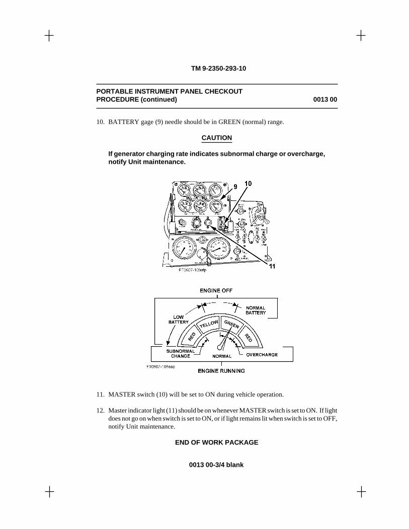
TM 9-2350-293-10
10. BATTERY gage (9) needle should be in GREEN (normal) range.
CAUTION
If generator charging rate indicates subnormal charge or overcharge,notify Unit maintenance.
11. MASTER switch (10) will be set to ON during vehicle operation.
12. Master indicator light (11) should be on whenever MASTER switch is set to ON. If lightdoes not go on when switch is set to ON, or if light remains lit when switch is set to OFF,notify Unit maintenance.
END OF WORK PACKAGE
PORTABLE INSTRUMENT PANEL CHECKOUTPROCEDURE (continued) 0013 00
0013 00-3/4 blank

TM 9-2350-293-10

TM 9-2350-293-10
0014 00-1
0014 00
OPERATION OF DOME LIGHTS
1. To set blue-green light to ON, turn knob (1) fully clockwise.
2. To set white light to ON, press safety switch (2) and turn knob (1) counterclockwisepast stop.
3. To set both lights to OFF, position knob (1) in center position.
OPERATOR'S MANUALCARRIER, AMMUNITION, TRACKED, M992A2
OPERATION OF DOME LIGHTS AND DRIVING LIGHTS
THIS WORK PACKAGE COVERS:Operation of Dome Lights and Light Switch Assembly
INITIAL SETUP:Maintenance Level
Operator

TM 9-2350-293-10
0014 00-2
1. Push up safety switch (2) to release main light switch (1). Release safety switch (2) aftermain light switch (1) is properly positioned.
2. Push up on instrument panel light switch (3) to turn on instrument panel lights.
OPERATION OF DRIVING LIGHTS AND DOME LIGHTS (continued) 0014 00
END OF WORK PACKAGE
OPERATION OF LIGHT SWITCH ASSEMBLY
The panels below show which lamps are turned on by different positions of main light switch.

TM 9-2350-293-10
The transmission is equipped with a shift inhibitor that restricts movement of the transmissionselector lever. This prevents downshifting of transmission until vehicle speed drops withincorrect operating limits for desired gear range.
While downshifting, always brake vehicle to prevent vehicle speed from overrunning enginespeed.
CAUTION
• Never descend an incline with transmission in neutral.
• Do not hold vehicle on incline with transmission in gear; instead,lock brake and shift transmission to neutral.
• Always shift to a lower transmission gear range when engine rpm isless than 1725.
0015 00
NEUTRAL (N) should be used when:
• Vehicle is stopped or parked.
• Engine is being started or shut down.
• Idling.
0015 00-1
OPERATOR'S MANUALCARRIER, AMMUNITION, TRACKED, M992A2
SHIFTING THE TRANSMISSION
INITIAL SETUP:Maintenance Level
Operator

TM 9-2350-293-10
FIRST GEAR (1) should be used when:
• Setting vehicle in forward motion duringfield operation. Upshift to higher gear whenvehicle speed permits.
• Ascending or descending steep grades anddriving on soft, muddy, or rough terrain.
• Making short, forward radius turns. Shortforward radius turns on hard surfaces shouldbe initiated from a standstill. Top speed is sixmiles per hour.
SECOND GEAR (2) should be used when:
• Towing heavy loads.
• Ascending or descending steep grades anddriving on extremely soft, muddy, or roughterrain.
• Making short, forward radius turns. Topspeed is nine miles per hour.
THIRD GEAR (3) should be used when:
• Vehicle is operating on hard-surfaced roads,until sufficient speed (12 to 15 mph) permitsshifting to FOURTH GEAR (4) range.
• Pulling heavy loads for sustained periodsand ascending or descending long grades.Top speed is 24 miles per hour.
SHIFTING THE TRANSMISSION (continued) 0015 00
0015 00-2

TM 9-2350-293-10
FOURTH GEAR (4) should be used when:
• Setting under normal conditions on firm,smooth, level ground. Top speed is 35miles per hour.
SHIFTING THE TRANSMISSION (continued) 0015 00
REVERSE–FIRST GEAR RANGE (R1)should be used when:
• Backing up.
• Making turns with heavy loads or when onsoft ground.
• Ascending steep grades backward, formaximum engine power.
• Making short, rearward radius turns.
REVERSE–SECOND GEAR RANGE (R2)should be used when:
• Driving on level, hard-surfaced ground whenbackward movement for long distancesbecomes necessary.
CAUTION
Never attempt to shift into reverse gear range unless vehicle is atstandstill and engine is operating at idle rpm.
END OF WORK PACKAGE
0015 00-3/4 blank

TM 9-2350-293-10

0016 00
WARNING
• Brake vehicle to prevent vehicle speed from overrunning enginespeed. If vehicle speed overruns engine speed, you will not be ableto downshift and may lose control of vehicle.
• Drive carefully, especially if unfamiliar with vehicle. Avoidoversteering and speeding on hard pavement; you could lose controlof vehicle.
• Be sure driver's and commander's hatches are locked in either theopened or closed position. To avoid injury to personnel, secureupper and lower rear doors, personnel side doors, and all othercovers in closed position before moving.
• Make sure charge canisters, projectiles, fuses, and all other stoweditems are securely restrained before moving vehicle.
• Never move vehicle without first receiving a signal from theammunition team chief that all crewmembers are seated and thatstowed items are secured. Always use seatbelts while traveling.
• For the safety of personnel in the area when backing up, position twoground guides who can clearly see each other; one should be ableto see the driver and the other should be able to see the area behindthe vehicle. If necessary, one on-board guide, using a CVC helmet,can direct the vehicle using AN/VIC-3(V) intercommunication withdriver.
OPERATOR'S MANUALCARRIER, AMMUNITION, TRACKED, M992A2
DRIVING THE VEHICLE
THIS WORK PACKAGE COVERS:Preparation for Movement and Moving the Vehicle
INITIAL SETUP:Maintenance Level
Operator
0016 00-1
TM 9-2350-293-10

WARNING
If you lose a track or break a track shoe, or if vehicle throws a track,extreme caution must be exercised in maintaining control. Immediatelyrelease accelerator pedal and let vehicle coast to a stop. Do notattempt braking action, brake pedal, laterals, pivot, or any type ofsteering controls. Braking causes vehicle to pull to the active (good)track and could result in a rollover. If absolutely necessary, attemptbraking action ONLY if vehicle is approaching a ravine or a cliff or ifyou perceive the outcome to be catastrophic, probably resulting infatalities. When rollover is imminent, all crewmembers shouldimmediately withdraw inside vehicle, tighten seatbelts, and hold onto a secure fixture until vehicle comes to a complete stop.
CAUTION
• Do not leave vehicle unattended while engine is running.
• When starting on a hill, depress brake and place transmission in firstgear. Increase engine speed and release brake.
• Do not hold vehicle on an incline by using accelerator pedal.Transmission overheating will result.
• Do not coast when descending grades; instead, downshifttransmission.
• Observe overhead and side clearances. When turning vehicle, allowample clearance for corners of vehicle. When making sharp turns,shift to first or second gear.
• If vehicle throws a track, do not use the brake to stop; instead, stopaccelerating and coast to a stop.
PREPARATION FOR MOVEMENT
Before moving the M992A2, check to see that all systems and cargo compartments aresecured for travel. The steps that follow present specific items to be checked before moving.
1. Make sure conveyor is properly stowed and secured (p. 0030 00-14).
DRIVING THE VEHICLE (continued) 0016 00
0016 00-2
TM 9-2350-293-10

PREPARATION FOR MOVEMENT (continued)
2. Make sure the following doors are closed and secured:
• Personnel side door (p. 0027 00-4)
• Canister side doors (p. 0027 00-5)
• Top (middle, left, and right) doors (pp. 0027 00-5 through 0027 00-7)
• Upper rear door (p. 0027 00-9) and dog doors (p. 0027 00-12)
• Lower rear door (p. 0027 00-8)
• APU side and front doors (pp. 0027 00-13 and 0027 00-14)
• Transmission access doors (p. 0027 00-2)
• Battery access doors (p. 0027 00-3)
• Fuel cap access door
• AFES fire extinguisher box door, vehicles S/N 345 and above
3. Make sure driver's hatch door and commander's cupola hatch door are secured in openposition (with hold-open latches) or in closed position (pp. 0027 00-14 and 0027 00-16).
4. Check to make sure the following items are secured with restraint straps (and bars, ifapplicable):
• Propelling-charge canisters (p. 0031 00-9)
• Fuse boxes
• Primer boxes
• 0.50-caliber ammunition boxes
5. Check to make sure all projectiles are locked in place (p. 0032 00-3).
6. Check to make sure all other loose items are stowed/secured.
DRIVING THE VEHICLE (continued) 0016 00
0016 00-3
TM 9-2350-293-10

DRIVING THE VEHICLE (continued) 0016 00
MOVING THE VEHICLE
1. Press down on brake pedal (1), andpull out on BRAKE LOCK handle(2).
2. With brake pedal (1) depressed andthrottle control lever (3) adjusted to idleposition, shift from N (neutral) to 1 (firstgear) (4).
3. Release brake pedal (1) and push accelerator pedal (5) to obtain desired speed. Shiftthrough intermediate ranges into desired speed range (pp. 0015 00-1 through 0015 00-3/4 blank).
4. To turn vehicle, turn steering wheel (6) in desired direction.
0016 00-4
TM 9-2350-293-10

END OF WORK PACKAGE
MOVING THE VEHICLE (continued)
CAUTION
When engine speed is less than 1725 rpm, shift to lower range.
5. Frequently check tachometer (7), speedometer (8), and other instrument panel gages.While driving the vehicle, check for unusual engine noises and vibration, and properoperation of steering and brakes.
0016 00-5/6 blank
DRIVING THE VEHICLE (continued) 0016 00
TM 9-2350-293-10


TM 9-2350-293-10
0017 00-1
0017 00
WARNING
• To avoid possible injury and vehicle damage, approach obstaclehead-on.
• Warn crewmembers to brace themselves.
• Hatches, doors, and stowed items must be secured before proceedingover obstacle.
1. Crossing a Ditch, Hole, or Trench. Apply brake and shift to first gear. When vehiclereaches bottom and starts to climb, depress accelerator to attain power needed to climbfree of obstacle.
2. Driving over Barrier (21 inches maximum vertical height). As vehicle approachesbarrier, release accelerator, apply brake, and shift to first gear. Apply full power whenstarting over barrier. Release accelerator pedal upon reaching crest and permit vehicleto settle over it. Balance vehicle forward of the crest to begin descent. When front oftracks touch ground, add power and move on.
3. Starting Vehicle on an Upgrade. To avoid rolling backward when vehicle is headeduphill, apply power before releasing brake.
CAUTION
• Do not use engine as a braking source for a long period of time.Transmission overheating will result.
• Using service brakes too long will burn them out. Release and applybrakes occasionally.
4. Descending Steep Grades. Shift transmission into first gear and apply brake as necessaryto slow vehicle.
OPERATOR'S MANUALCARRIER, AMMUNITION, TRACKED, M992A2
DRIVING OVER ROUGH, SOFT, OR HILLY TERRAIN
INITIAL SETUP:Maintenance Level
Operator

TM 9-2350-293-10
0017 00-2
DRIVING OVER ROUGH, SOFT, OR HILLY TERRAIN (continued) 0017 00
CAUTION
Making sharp turns in first gear may cause a track to be thrown.
5. Driving in Loose Sand, Dirt, or Rocks. Shift into first gear and make series of short,gradual turns. This action will allow debris to be expelled from track.
END OF WORK PACKAGE

TM 9-2350-293-10
0018 00-1
0018 00
1. Release accelerator pedal (1) and slowly depressbrake pedal (2) until vehicle stops.
NOTE
Before applying the servicebrake while on steep slopes(greater than 20 percent),adjust the driver's seat soyou can apply maximumleverage to the brake.
OPERATOR'S MANUALCARRIER, AMMUNITION, TRACKED, M992A2
STOPPING THE VEHICLE
INITIAL SETUP:Maintenance Level
Operator
2. With brake pedal (2) depressed, shift transmission selector lever (3) into neutral andpull parking BRAKE LOCK handle (4) out and down. Release brake pedal (2). Ifstopping on a steep slope, press on brake pedal (2) after pulling BRAKE LOCKhandle (4) out and down.

TM 9-2350-293-10
0018 00-2
STOPPING THE VEHICLE (continued) 0018 00
CAUTION
Failure to perform steps 3 and 4 beforeshutting down engine may result inengine damage.
3. Set throttle control lever (5) to run engine at 1000–1200 revolutions per minute on tachometer. Runengine at this speed for three to five minutes oruntil coolant temperature measures 185°F or less.
4. Set throttle control lever (5) forward to returnengine to normal idle (550–600 rpm). Idle one tothree minutes before stopping engine.
5. Turn communications switch (6) to OFF.
6. Turn off all light switches and accessory switchesin driver's compartment and crew/cargocompartment.
7. Pull out FUEL SHUT OFF handle (7) to stopengine.
WARNING
If engine does not stop when FUELSHUT OFF handle is pulled, follow step8. Failure to comply with this step mayresult in injury to personnel.
8. If engine does not stop when FUEL SHUT OFFhandle (7) is pulled, open engine intake grille andturn lever (8) on engine. Hold lever (8) until enginestops.
9. Turn MASTER switch to OFF.
10. Do after-operation PMCS (WP 0050 00-1 throughWP 0050 00-10).
END OF WORK PACKAGE

TM 9-2350-293-10
0019 00-1
0019 00
WARNING
For the safety of personnel in the area when backing up, position twoground guides who can clearly see each other; one should be able tosee the driver and the other should be able to see the area behind thevehicle. If necessary, one on-board guide, using a CVC helmet, candirect the vehicle using AN/VIC-3(V) intercommunication with driver.
BACKING WITH TWO OR MORE GROUND GUIDES
1. Ground guides must be positioned so they can see obstructions behind vehicle and canrelay backing instructions to driver.
2. Ground guide at rear of vehicle will check vehicle path and manually signal backinginstructions to front guide.
3. Front guide will relay backing instructions to driver.
4. Driver will back vehicle slowly and according to instructions.
OPERATOR'S MANUALCARRIER, AMMUNITION, TRACKED, M992A2
BACKING THE VEHICLE
THIS WORK PACKAGE COVERS:Backing with Two or More Ground Guides and Backing with One On-BoardGuide
INITIAL SETUP:Maintenance Level Personnel Required
Operator Two or Three

TM 9-2350-293-10
0019 00-2
BACKING THE VEHICLE (continued) 0019 00
END OF WORK PACKAGE
BACKING WITH ONE ON-BOARD GUIDE
1. Open lower and upper rear doors (pp. 0027 00-8 and 0027 00-9).
2. Driver and guide will connect CVC helmet cables to control box receptacles and switchon intercommunications equipment. Guide must use control box just inside vehicle reardoorway.
3. Driver and guide will establish intercommunications via communications equipment.
WARNING
• For the safety of personnel in the area, driver must stop vehicle ifcommunications are interrupted during backing operations.
• To avoid damage to upper rear door and injury to personnel in thearea, on-board guide must always consider rear clearance of openeddoor when instructing driver.
4. From rear doorway, guide will check vehicle path. Guide will verbally instruct driverin backing vehicle.
5. Driver will back vehicle slowly and according to instructions.
6. Guide and driver will continue in this manner until backing operations are complete.
7. After vehicle is properly positioned, turn off intercommunications equipment andremove and stow CVC helmets.

TM 9-2350-293-10
0020 00-1
0020 00
NOTE
• The M992A2 is authorized to tow only one vehicle at a time andonly when the other vehicle is disabled, or when towing tostart engine.
• In an emergency you can tow a vehicle for a short distance (notmore than 1/4 mile) without disconnecting universal joints.Put transmission selector lever in N (neutral) before startingtowing operation. Do not tow disabled vehicle over 10 milesper hour. Be careful not to accidently shift into gear.
• The M992A2 is authorized to carry either a 10-foot or a 15-foottow cable. The 15-foot tow cable is to be used only withM109A6 vehicles.
OPERATOR'S MANUALCARRIER, AMMUNITION, TRACKED, M992A2
TOWING OPERATIONS
THIS WORK PACKAGE COVERS:Towing Precautions, Removal, Installation, Towing, and Towing Vehicle toStart Engine
INITIAL SETUP:Maintenance Level Personnel Required
Operator Two
Tools/Test Equipment ReferencesHandle, socket wrench (Item 24, WP 0075 00) TM 9-4910-496-10Pliers (Item 44, WP 0075 00)Socket, Socket Wrench (Item 51, WP 0075 00)Socket, Socket Wrench (Item 53, WP 0075 00)Socket, Socket Wrench (Item 54, WP 0075 00)

TM 9-2350-293-10
0020 00-2
TOWING OPERATIONS (continued) 0020 00
TOWING PRECAUTIONS
The following precautions should be followed to ensure safety to personnel and to preventdamage to equipment:
• Vehicle engines will be shut off and brakes applied while tow cables are beingconnected or disconnected.
• There must be an observer to assist driver when rigging vehicle and during towingoperations.
Tow Cable, 10-foot
1. Remove two screws, lockwashers, and clamps securing tow cable to hull to remove towcable from vehicle.
2. Install tow cable on vehicle. Secure with two clamps, screws, and new lockwashers.
Tow Cable, 15-foot
WARNING
The 15-foot tow cable is very heavy. Two persons are required whenremoving/installing tow cable from/on stowage mounts.
REMOVAL
1. Open APU front door.
2. Remove screw, washer, and tow cable strap from upper stowage mount.
3. Pull tow cable away from six tow cable supports and set on engine grille.
4. Remove screw, washer, tow cable strap, and tow cable from lower stowage mount.
5. Close APU front door.

TM 9-2350-293-10
0020 00-3
INSTALLATION
1. Open APU front door.
2. Place one end of tow cable in lower stowage mount and secure with tow cable strap,washer, and screw.
3. Position tow cable in six tow cable supports.
4. Place other end of tow cable in upper stowage mount and secure with tow cable strap,washer, and screw.
5. Close APU front door.
TOWING
WARNING
When tow bars or cables are used, a second vehicle is required whendescending a grade of 20 degrees or more, or if road conditions requireadditional power. Do not exceed 10 miles per hour.
CAUTION
• When universal joints are disconnected, you cannot steer or brake.Use tow bar only.
• Stow universal joints and flanges where they will remain clean and freeof dirt. Failure to do so may result in damage to equipment.
1. Follow steps a through l to disconnect universal joints.
WARNING
• Never disconnect final drives on a disabled vehicle without firstchocking the track and/or hooking up a tow bar to the recovery vehicle.
• Never disconnect the final drives on an incline or leave a disabledvehicle on an incline with final drives disconnected. Hook up a tow barto the disabled vehicle and, using a recovery vehicle, move thedisabled vehicle to firm level ground (chock blocks alone may notprevent a vehicle from moving).
TOWING OPERATIONS (continued) 0020 00

TM 9-2350-293-10
0020 00-4
TOWING (continued)
WARNING
When hooking or unhooking tow bar or tow cable from a disabledvehicle, chock tracks of disabled vehicle before hooking or unhookingtow bar or tow cable. If towed vehicle is not chocked it may move,causing injury or death to personnel and/or damage to equipment.
CAUTION
• When removing right-side universal joint, be careful not to damagefiberglass fuel tank.
• When removing universal joints, be sure to use strap to secureuniversal joint to avoid damaging fire wire.
• When removing left-side universal joint, be sure to disconnect lead503 to avoid damaging lead.
NOTE
Use chock blocks made of hard wood or other suitable materials. DONOT use decaying or rotted wood.
TOWING OPERATIONS (continued) 0020 00
a. Place chock blocksbetween two sets ofroadwheels on each trackor under the front and rearof both tracks. Open rightand left transmission doors.
b. Run an equipment tiedownstrap (2) through left-sideuniversal joint (1). Toprevent universal joint (1)from falling, have anassistant hold strap (2) taut.

TM 9-2350-293-10
0020 00-5
TOWING OPERATIONS (continued) 0020 00
TOWING (continued)
c. Cut lockwire (4) and remove twoquick-disconnect screws (5)from each of two coupling sets(6).
d. Remove two coupling sets (6)from two universal joint adapters(8).
e. Pry both final drive flanges (3)away from universal joint (1).Move flanges (3) toward finaldrive housing (9).
WARNING
Universal joints are heavy.Keep hands out fromunderneath universal jointswhen they are disconnected.Failure to do so may resultin injury to personnel.
f. Before removing left-sideuniversal joint (1) from vehicle,disconnect lead 503 (10).
g. Pry universal joint (1) loose fromtransmission flange (7) and, withthe aid of an assistant, removeleft-side universal joint (1) fromvehicle.
h. Disconnect fuel-line quickdisconnect (12) from fuel filter(13). Remove front bolt (14)and rear bolt (15) from fuel filterbracket (11) (lifting point forpowerpack). Leave center boltin place for pivot.

TM 9-2350-293-10
0020 00-6
TOWING (continued)WARNING
Universal joints are heavy. Keep hands out from underneath universaljoints when they are disconnected. Failure to do so may result in injuryto personnel.
i. Rotate bracket (11) back far enough to get proper clearance and, with the aid of anassistant, remove right-side universal joint (16) from vehicle.
j. Remove final drive flange (3) from final drive shaft (17) for both universal joints.
TOWING OPERATIONS (continued) 0020 00
k. Rotate bracket (11) back intoposition and install front and rearbolts (14 and 15) on bracket (11).
l. Connect fuel-line quickdisconnect (12) to fuel filter (13)and lead 503 (10).

TM 9-2350-293-10
0020 00-7
TOWING OPERATIONS (continued) 0020 00
TOWING (continued)NOTE
Check fluid level in final drive after installing universal joints.You can lose fluid with final drive flange off.
2. Install tow bar or tow cable (refer to TM 9-4910-496-10).
3. Shift transmission in disabled vehicle into N (neutral).
CAUTION
To avoid collision when towing, be sure to steer in a wide arc whenturning.

TM 9-2350-293-10
0020 00-8
TOWING VEHICLE TO START ENGINE
CAUTION
When an M992A2 is towing to start anM109-family vehicle, M109 cab shouldbe turned 180 degrees to keep tubefrom striking M992A2.
1. Connect tow bar or tow cables (refer to TM 9-4910-496-10).
2. Shift transmission selector lever (1) into secondgear.
3. Depress brake pedal (2) and release parkingBRAKE LOCK handle (3).
CAUTION
Never depress accelerator pedal ontowed vehicle.
4. Tow vehicle in straight line forward. Do notexceed 10 miles per hour.
5. After engine in M109-family vehicle starts,shift to N (neutral) and adjust throttle controllever (4) to run engine at a fast idle(approximately 1000 rpm).
6. Once vehicles come to a stop, disconnect towbar or tow cables (refer to TM 9-4910-496-10).
TOWING OPERATIONS (continued) 0020 00
END OF WORK PACKAGE

OPERATOR'S MANUALCARRIER, AMMUNITION, TRACKED, M992A2
OPERATING THE BILGE PUMP
INITIAL SETUP:Maintenance Level
Operator
CAUTION
Do not operate bilge pump for more than 1 minute if dry, or more than15 minutes if wet, without starting engine.
To drain water out of engine compartment, turn MASTER switch (1) and BILGE PUMPswitch (2) to ON.
END OF WORK PACKAGE
00021 00
0021 00-1/2 blank
TM 9-2350-293-10


0022 00
DEPLOYMENT
1. Make sure quick-release pin (2) is installed in footrest (3).
WARNING
• Always support footrest before you remove quick-release pin.Failure to do this will allow footrest to swing freely, which couldcause serious injury.
• Before deploying footrest, make sure quick-release pin is securelypositioned through holes in footrest tubes. If pin is not properlyinserted, footrest will telescope when lowered and may causeinjury.
2. Support footrest (3) and remove quick-release pin (1) from footrest (3). Slowly lowerfootrest (3) and allow it to hang freely.
0022 00-1
OPERATOR'S MANUALCARRIER, AMMUNITION, TRACKED, M992A2
COMMANDER'S SEAT
THIS WORK PACKAGE COVERS:Deployment, Adjustment, and Stowing
INITIAL SETUP:Maintenance Level Personnel Required
Operator Two
TM 9-2350-293-10

DEPLOYMENT (continued)
WARNING
Commander's seat assembly is very heavy. It must be adequatelysupported before quick-release pin is removed. Failure to do so mayresult in serious injury. Deployment of commander's seat shall alwaysbe a two-person operation.
NOTE
An assistant is needed to help support seat assembly and preventfootrest from swinging freely.
3. While supporting seat post (8) and footrest (3), remove quick-release pin (9) from supportbracket (4) and then remove pin (7) from bracket (6). Slowly lower seat assembly (5).Reinsert pin (7) into seat-stowage hole and reinsert quick-release pin (9) into supportbracket (4).
COMMANDER'S SEAT (continued) 0022 00
0022 00-2
TM 9-2350-293-10

DEPLOYMENT (continued)
4. Pivot footrest (3) forward and up. Alignforward holes and insert quick-release pin(11) in footrest (3).
WARNING
To avoid injury, seat must besupported before removingquick-release pin.
5. Support seat (10) and remove quick-releasepin (12) from seat (10). Pivot seat (10)downward. Align holes and insert quick-release pin (12) in seat (10).
ADJUSTMENT
1. Backrest Adjustment. Remove quick-release pin (2) from seat (5). Rotate backrest(1) up for sitting, down for standing. Alignpinholes and insert quick-release pin (2) inbackrest (1).
2. Footrest Adjustment. Remove quick-release pin (4) from footrest (3). Slidefootrest (3) in or out to desired position.Align holes in footrest (3) and install quick-release pin (4) in footrest (3).
COMMANDER'S SEAT (continued) 0022 00
0022 00-3
TM 9-2350-293-10

COMMANDER'S SEAT (continued) 0022 00
0022 00-4
ADJUSTMENT (continued)
WARNING
To avoid injury, sit on seat to applydownward pressure before adjustingheight-adjusting handle.
CAUTION
Do not use handle guard for lifting; itis meant to prevent accidentalactuation of the handle.
TM 9-2350-293-10
3. Seat Height Adjustment. Apply downwardpressure to seat (5) and pull adjustinghandle (6) forward. Increase or decreasepressure on handle (6) to lower or raise seat(5). When desired height is achieved,release handle (6) and slowly releasepressure until seat (5) locks into position.
STOWING
WARNING
To avoid injury, sit on seat to applydownward pressure before adjustingheight-adjusting handle.
1. Apply downward pressure to seat (2) and pulladjusting handle (1) forward. Press seat (2) toits lowest point. Release handle (1) andslowly release pressure until seat (2) locksinto position.

COMMANDER'S SEAT (continued) 0022 00
0022 00-5
STOWING (continued)
2. Remove quick-release pin (5) from footrest(6). Push footrest (6) in as far as it will go.Align pinholes in footrest (6) and insertquick-release pin (5).
3. Remove quick-release pin (4) from seat (2)and pivot backrest (3) down. Align pinholesin seat (2) and insert quick-release pin (4).
4. Remove quick-release pin (7) from seat (2)and pivot seat (2) up. Align pinholes in seat(2) and install quick-release pin (7).
WARNING
• Before lowering footrest, makesure quick-release pin issecurely inserted throughholes in footrest tubes. If pinis not properly inserted,footrest will telescope whenlowered and may cause injury.
• Always support footrest beforeyou remove quick-release pin.Failure to do this will allowfootrest to swing freely, whichcould cause serious injury.
5. Support footrest (6) and remove quick-releasepin (8) from footrest (6). Slowly lower footrest(6) and allow it to hang freely.
TM 9-2350-293-10

COMMANDER'S SEAT (continued) 0022 00
STOWING (continued)WARNING
To avoid injury, use two people to lift seat assembly for stowage.
CAUTION
If commander's cupola periscope is to remain installed, you must rotatecupola so that periscope is 90 degrees left of forward before you raiseseat assembly. Failure to do this may result in destruction of periscope.If periscope is removed, cupola may remain forward when seat is stowed.
NOTE
Have an assistant help lift and support seat and prevent footrest fromswinging.
END OF WORK PACKAGE
0022 00-6
6. Remove two quick-release pins (11 and 10) frombracket (12) and support bracket (9). Pivot seat (2)forward and upward until holes in seat post (13)align, and insert quick-release pin (10) in supportbracket (9). Install quick-release pin (11) in bracket(12).
7. Pivot footrest (6) toward rear and up. Align pinholesin footrest (6) and install quick-release pin (8) infootrest (6).
TM 9-2350-293-10

OPERATOR'S MANUALCARRIER, AMMUNITION, TRACKED, M992A2
ROTATING COMMANDER'S CUPOLA
0023 00
INITIAL SETUP:Maintenance Level
Operator
CAUTION
Never attempt to rotate commander's cupola while commander's seatis stowed. Such an attempt will damage seat-height adjusting handle.
1. Deploy commander's seat (WP 0022 00-1).
2. Pull out on latch handle (2). Rotate cupola to desired position.
3. Release latch handle (2) into one of 12 notches (1) around cupola circumference.
END OF WORK PACKAGE
0023 00-1/2 blank
TM 9-2350-293-10


TM 9-2350-293-10
0024 00-1
OPERATOR'S MANUALCARRIER, AMMUNITION, TRACKED, M992A2
CREW SEATS
0024 00
THIS WORK PACKAGE COVERS:Operation of Left Front Seat and Right Front Double Seat
INITIAL SETUP:Maintenance Level Personnel Required
Operator Two
WARNING
Seats are heavy. Support seats before pulling quick-release pins.Hinged seats, backrests, and support brackets may swing down,causing personal injury.
NOTE
To allow for maximum work space, stow all seats prior to working invehicle. Stow seats in reverse order of deployment.
LEFT FRONT SEAT
1. Grasp seat backrest (2) and seat (5) androtate seat backrest (2) and seat (5) up andback. Pivot bracket (4) into slot (3).
2. Raise seat backrest (2) until support joint(1) is locked.

TM 9-2350-293-10
0024 00-2
CREW SEATS (continued) 0024 00
RIGHT FRONT DOUBLE SEAT
1. Pull up on seat backrest (3). As seatbackrest (3) passes horizontal, seat (1)will pivot upward.
2. As seat backrest (3) and seat (1) reach fulldeployment, pivot bracket (5) into slots (4).
3. Before releasing seat backrest (3), make suresupport joint (2) is locked.
WARNING
Seat is heavy and difficult to maneuver alone. To avoid injury, get anassistant to help you before proceeding.
4. To remove seat, remove two quick-release pins (6) securing seat (1) to right-handsponson.
END OF WORK PACKAGE

TM 9-2350-293-10 0025 00
STARTINGCAUTION
To avoid damaging radio components, turn off all radio switchesbefore starting the APU.
1. Open APU front door and check APU engine oil level. Add oil to bring level to full (F)mark on dipstick. Add or drain as necessary.
2. Turn off all electrical and radio switches.
3. Turn vehicle MASTER switch to ON.
NOTE
The APU will not start if APU GEN switch is set to ON.
0025 00-1
OPERATOR'S MANUALCARRIER, AMMUNITION, TRACKED, M992A2
OPERATING THE AUXILIARY POWER UNIT (APU)
THIS WORK PACKAGE COVERS:Starting, Shutting Down, Electrical Support of Another Vehicle, and ChargingLow Batteries with the APU
INITIAL SETUP:Maintenance Level References
Operator TM 9-6140-200-14
4. Make sure APU GEN switch (1)is set to OFF.

TM 9-2350-293-10
OPERATING THE APU (continued) 0025 00
STARTING (continued)
5. Turn FUEL SHUT OFF switch (2) to ON. The LOW OIL PRESS lamp (4) will light untilAPU engine starts.
6. Turn PREHEAT switch (3) to MOM ON. Hold switch to MOM ON for 20 seconds ifoutside air temperature is above 55°F (12.8°C). Hold switch to MOM ON for one minuteif outside air temperature is between 0°F and 55°F (-17.8°C and 12.8°C). If airtemperature is below 0°F (-17.8°F), refer to page 0036 00-1.
NOTE
If APU engine does not start within one minute, release STARTswitch but continue to hold PREHEAT switch to ON for another 20seconds (in temperatures above 55°F, 12.8°C) or one minute (intemperatures below 55°F, 12.8°C). After allotted time, hold STARTswitch to MOM ON again. If engine still does not start, troubleshootAPU engine (p. 0047 00-10).
7. While holding PREHEAT switch (3) to MOM ON, move START switch (5) to MOM ON.Hold both switches (3 and 5) on for about 2 to 5 seconds, then release. APU engine shouldstart.
0025 00-2

TM 9-2350-293-10
STARTING (continued)CAUTION
• To avoid damaging the APU engine, if LOW OIL PRESS lamp remainslit after engine starts, or if it lights during APU operation, turn FUELSHUT OFF switch to OFF to stop the APU. Notify Unit maintenance ifthis problem occurs.
• When operating the APU at high altitudes and/or high temperatures,continuous heavy-load demands by the electrical and hydraulic systemsmay cause APU engine to overheat. In these extreme conditions, theAPU GEN switch should be turned to OFF and hydraulic componentsshould be shut down periodically. Continue to run the APU withoutload for several minutes before again operating generator and hydrauliccomponents.
• If HIGH AIR TEMP lamp lights during operation, turn FUEL SHUT OFFswitch to OFF. Allow the APU to cool before restarting. Notify Unitmaintenance if lamp lights often.
8. While the APU is operating, check LOW OIL PRESS lamp (4), HIGH AIR TEMP lamp(7), and ENGINE OIL PRESSURE gage (6) for APU malfunctions. ENGINE OILPRESSURE gage (6) should indicate 25-35 psi.
OPERATING THE APU (continued) 0025 00
0025 00-3
SHUTTING DOWN
1. Turn APU GEN switch (1) toOFF.
2. Turn FUEL SHUT OFF switch(2) to OFF.
3. Turn vehicle MASTER switchto OFF.

TM 9-2350-293-10
.
4. If the APU continues to run with MASTER switchset to OFF, open APU side door and disconnectfuel line (8) to APU fuel filters. Notify Unitmaintenance.
ELECTRICAL SUPPORT OF ANOTHERVEHICLE
Under normal conditions, the APU generator cansupply enough electrical power to operate its ownelectrical system and that of another vehicle thatpossesses a compatible electrical system. There arelimitations to the generator's output, however. Whenyour vehicle's hydraulic system operates under load,
OPERATING THE APU (continued) 0025 00
SHUTTING DOWN (continued)
0025 00-4
the generator may occasionally switch off. This is only a temporary situation, and thegenerator will automatically switch on when hydraulic pressure decreases.
1. Park your vehicle close enough to the supported vehicle so the slave cable can beinterconnected at the slave receptacle connectors of both vehicles. If your M992A2 isto support a self-propelled howitzer (M109A2, M109A3, or M109A6) during conveyoroperation, position your vehicle back-to-back with the howitzer and deploy theconveyor (p. 0030 00-1).
2. With the brake pedal (3) depressed, place the transmission shift selector lever (1) in N(neutral) and set parking BRAKE LOCK handle (2).

TM 9-2350-293-10
OPERATING THE APU (continued) 0025 00
ELECTRICAL SUPPORT OF ANOTHER VEHICLE (continued)
WARNING
Turn MASTER switch and all other electrical switches in both vehiclesto OFF to avoid personal injury or vehicle damage.
3. Shut down main engine in both vehicles (p. 0018 00-1). Turn MASTER switches toOFF in both vehicles.
4. Attach slave cable (5) to slave receptacle connectors (4) on both vehicles. Use adapter(Item 1, p. 0075 00-4), if necessary.
0025 00-5

TM 9-2350-293-10
ELECTRICAL SUPPORT OF ANOTHER VEHICLE (continued)
5. Turn your vehicle's MASTER switch to ON and start the APU (p. 0025 00-1).
6. Allow the APU to warm up for three minutes, then turn APU GEN switch (6) to ON.
7. Turn on MASTER switch in supported vehicle to make power available to it.
NOTE
Check BATTERY gage in each vehicle at least once per hour.
8. If charge indicator needle (9) drops below halfway in yellow range (8) in either vehicle,turn APU GEN switch (6) to OFF and start both main engines. While trying to startdisabled vehicle's main engine, do not rev functional vehicle's main engine. Allowengines to run until both charge indicator needles are in normal range. If needles indicatelow charge, continue to run the APU until needles are halfway in yellow range, thenrepeat this step.
OPERATING THE APU (continued) 0025 00
0025 00-6
9. To stop this operation, turn APU GEN switch (6) to OFF and turn APU FUEL SHUT OFFswitch (7) to OFF.
WARNING
To avoid injury, turn MASTER switches to OFF in both vehicles beforedisconnecting slave cable.
10. Turn MASTER switch to OFF in both vehicles.
11. Disconnect and stow slave cable.

TM 9-2350-293-10
CHARGING LOW BATTERIES WITH THE APU
NOTE
This procedure applies only to vehicles with low-charge batteries. If nogages or lights function on a vehicle when its MASTER switch is on,batteries are dead. To charge dead batteries, refer to Charging DeadBatteries with the APU (p. 0025 00-11).
1. Before trying to charge batteries, do the following:
a. Check batteries for broken cases or cables, severe corrosion, and other damage.Notify Unit maintenance if batteries are damaged.
b. Check electrolyte level (refer to TM 9-6140-200-14). Add distilled water asnecessary.
OPERATING THE APU (continued) 0025 00
0025 00-7
2. Park your vehicle close enough to supported vehicle so that slave cable can be interconnectedat slave receptacles of both vehicles.

TM 9-2350-293-10
CHARGING LOW BATTERIES WITH THE APU (continued)
3. With brake pedal (3) depressed, place shift lever (1) in N (neutral) and set parking BRAKELOCK handle (2).
WARNING
To avoid personal injury and vehicle damage, turn off MASTER switchand all other electrical switches in both vehicles.
4. Shut down vehicle main engine (p. 0018 00-1). Turn MASTER switch to OFF in bothvehicles.
OPERATING THE APU (continued) 0025 00
0025 00-8

TM 9-2350-293-10
OPERATING THE APU (continued) 0025 00
0025 00-9
CHARGING LOW BATTERIES WITH THE APU (continued)
5. Attach slave cable (5) to slave receptacle (4) on both vehicles.
6. Turn your vehicle's MASTER switch to ON and start the APU (p. 0025 00-1).
7. Allow the APU to warm up for threeminutes, then turn APU GEN switch (6) toON.
8. Turn MASTER switch to ON in supportedvehicle to charge batteries.

TM 9-2350-293-10
OPERATING THE APU (continued) 0025 00
NOTE
You may start your vehicle's mainengine to increase powergeneration. Make sure APU GENswitch is set to OFF before youstart main engine. Once mainengine is started, reset APU GENswitch to ON.
0025 00-10
CHARGING LOW BATTERIES WITH THE APU (continued)
CAUTION
Starting your own vehicle or slave starting another vehicle with APUGEN switch set to ON while the APU is running can cause damage toAPU starter/generator. When starting your vehicle or slave startinganother vehicle, make sure APU GEN switch is set to OFF. Slavestarting another vehicle with the functioning vehicle's main engine onand being revved can cause damage to its charging system. To preventthis, have main engine at idle (600 rpm) or turned off.
9. Continue charging batteries until chargeindicator in supported vehicle reads well intonormal range.
10. Turn APU GEN switch (6) to OFF, and turnFUEL SHUT OFF switch (7) to OFF to shutdown the APU.
WARNING
To avoid injury, turn MASTER switches in both vehicles to OFF beforedisconnecting slave cable.
11. Turn MASTER switch to OFF in each vehicle.
12. Disconnect and stow slave cable.

TM 9-2350-293-10
OPERATING THE APU (continued) 0025 00
0025 00-11
CHARGING DEAD BATTERIES WITH THE APU
NOTE
This procedure applies only to vehicles with dead batteries. If anylights or gages function when a vehicle's MASTER switch is on,batteries are low, not dead. To charge low batteries, see page 002500-8.
1. Before trying to charge batteries, do the following:
a. Check batteries for broken cases or cables,severe corrosion, and other damage. If batteriesare damaged, notify Unit maintenance.
b. Check electrolyte level (refer to TM 9-6140-200-14). Add distilled water as necessary.
WARNING
Make sure that vehicles do not touch during this operation. Shortingthrough vehicles could cause serious injury to personnel and/orequipment damage.
2. Park your vehicle close enough to supported vehicle so that slave cable can beinterconnected at slave receptacle of each vehicle.

TM 9-2350-293-10
OPERATING THE APU (continued) 0025 00
0025 00-12
CHARGING DEAD BATTERIES WITH THE APU (continued)
NOTE
Before applying the service brake while on steep slopes (greater than20 percent), adjust the driver's seat so you can apply maximumleverage to the brake.
3. With brake pedal (3) depressed, place transmission selector lever (1) in N (neutral) andset parking BRAKE LOCK handle (2). If stopping on a steep slope, apply brake pedal(3) again after setting parking BRAKE LOCK handle (2).
WARNING
To avoid personal injury and vehicle damage, turn off MASTER switchand all other electrical switches in both vehicles.
4. Shut down vehicle main engine (p. 0018 00-1). Turn MASTER switch to OFF in bothvehicles.

TM 9-2350-293-10
OPERATING THE APU (continued) 0025 00
0025 00-13
CHARGING DEAD BATTERIES WITH THE APU (continued)
5. Attach slave cable (5) to slave receptacle connector (4) on both vehicles.
6. Turn your vehicle's MASTER switch to ON and start the APU (p. 0025 00-1).
7. Allow the APU to warm up for threeminutes, then turn APU GEN switch (6)to ON.
8. Turn MASTER switch in supportedvehicle to ON.
9. After five minutes of charging, turn FUELSHUT OFF switch (7) to OFF to shutdown the APU.
10. Turn your vehicle MASTER switch toOFF.

TM 9-2350-293-10
11. If gages or lights do not function in supported vehicle, return to step 6. If an additionalfive minutes of charging does not charge battery sufficiently for gage and lightfunctioning, notify Unit maintenance.
12. If batteries in supported vehicle activate gages or lights unaided by the APU, chargebattery as follows:
OPERATING THE APU (continued) 0025 00
CAUTION
• Do not attempt to start disabled vehicle with power from APU starter/generator. Doing this can cause damage to APU starter/generator.The APU is for recharging purposes during slaving procedures only.
• Be sure APU GEN switch is off before turning APU FUEL SHUT OFFswitch to OFF.
13. Turn FUEL SHUT OFF switch (7) to OFF.
WARNING
To avoid injury, turn off MASTER switches in both vehicles beforedisconnecting slave cable.
14. Turn MASTER switch to OFF in each vehicle.
15. Disconnect and stow slave cable.
0025 00-14
CHARGING DEAD BATTERIES WITH THE APU (continued)
a. Turn MASTER switch to ON in yourvehicle.
b. Start the APU (p. 0025 00-1).
c. Turn APU GEN switch (6) to ON.
d. Turn MASTER switch to ON insupported vehicle. Batteries willcharge.
e. Continue to charge batteries untilcharge indicator in supported vehiclereads well into normal range.
END OF WORK PACKAGE

OPERATING THE HYDRAULIC PUMP
NOTE
The M992A2 uses a hydraulic pump to provide power for operation ofconveyor and upper rear door (ballistic shield). The hydraulic pumpis driven by the APU and should be used during normal operation.
1. Start the APU (p. 0025 00-1).
2. Check pressure gage (1) on hydraulic control panel/hydraulic manifold. With pumpoperating but no hydraulic actuators operating, pressure gage should indicate between100 and 300 psi.
3. Operate hydraulic system as necessary.
4. To turn off hydraulic pump, shut down the APU (p. 0025 00-4).
END OF WORK PACKAGE
0026 00-1/2 blank
0026 00TM 9-2350-293-10
OPERATOR'S MANUALCARRIER, AMMUNITION, TRACKED, M992A2
HYDRAULIC PUMP OPERATION
INITIAL SETUP:Maintenance Level
Operator


TM 9-2350-293-10 0027 00
0027 00-1
OPERATOR'S MANUALCARRIER, AMMUNITION, TRACKED, M992A2
OPERATING DOORS
THIS WORK PACKAGE COVERS:Air Intake Grille, Transmission Access Doors, Battery Access Doors, PersonnelSide Door, Canister Side Doors, Top Middle Door, Top Side Doors (Left and Right),Lower Rear Door, Upper Rear Door, Dog Doors, APU Side Door, APU Front Door,Driver's Hatch Door, Commander's Cupola, and AFES Fire Extinguisher Box Door
INITIAL SETUP:Maintenance Level Personnel Required
Operator One to Three
WARNING
• To avoid injury, doors that must be open when loading or unloadingammunition should be secured when opened.
• To avoid damage or injury, close and secure all doors before movingvehicle.
• Keep hands, feet, and head clear of door when opening or closing anydoor. Use lifting rings for hand grasps when possible.
• Stand clear when opening or closing upper rear door (ballistic shield).If you open or close this door from outside vehicle (using bottomswitch), keep head and shoulders out of door's travel path.
AIR INTAKE GRILLE
Opening Air Intake Grille
WARNING
Make sure quick-release pin is properly installed to secure latch inlocked position. Failure to do so will cause severe injury to personnel.

TM 9-2350-293-10
OPERATING DOORS (continued) 0027 00
AIR INTAKE GRILLE (continued)
Unscrew two handles (2) to release air intake grille (1). With the aid of an assistant, raise intakegrille (1) and secure with quick-release pin (4) in intake grille support (3).
Transmission access doors are very heavy. Keep hands clear whenopening or closing doors.
NOTE
Right transmission access door must be opened before lefttransmission access door.
1. Unscrew handle (2) and, with the aid of an assistant, open right transmission access door(1).
2. Grasp handle (4) and, with the aid of an assistant, open left transmission access door (3).
0027 00-2
Closing Air Intake Grille
Remove quick-release pin (4) from intake grille support (3) and, with the aid of an assistant,close air intake grille (1). Screw in two handles (2) to secure air intake grille (1).
TRANSMISSION ACCESS DOORS
Opening Transmission Access Doors
WARNING

TM 9-2350-293-10
OPERATING DOORS (continued) 0027 00
1. Grasp handle (4) and, with the aid of an assistant, close left transmission access door (3).
2. With the aid of an assistant, close right transmission access door (1). Screw in handle (2)to secure right transmission access door (1).
BATTERY ACCESS DOORS
Opening Battery Access Doors
WARNING
Battery access doors are very heavy. Keep hands clear when openingor closing doors.
Unscrew handle (1) on each of two battery access doors (2) and, with the aid of an assistant,open doors (2)
Closing Battery Access Doors
With the aid of an assistant, closeeach of two doors (2) and screw ineach of two handles (1).
TRANSMISSION ACCESS DOORS (continued)
Closing Transmission Access Doors
NOTE
Left transmissionaccess door must beclosed before rightt r a n s m i s s i o naccess door.
0027 00-3

TM 9-2350-293-10
OPERATING DOORS (continued) 0027 00
PERSONNEL SIDE DOOR
NOTE
Latch handle is on outside of door only.
1. To open door (2), turn latch handle (1) counterclockwise to unlock, then clockwise tounlatch. Swing door (2) open.
2. Secure door (2) open with hold-open latch (3).
3. To close door (2), release hold-open latch (3) by pulling knob (4). Push door (2) closed.Make sure door (2) latches securely.
0027 00-4

TM 9-2350-293-10
OPERATING DOORS (continued) 0027 00
CANISTER SIDE DOORS
NOTE
Latch handles are on inside of doors only.
1. Turn latch handle (1) counterclockwise tounlock, then clockwise to unlatch door (2).Swing door (2) open.
2. Secure door (2) open with hold-open latch (3).
3. To close either door (2), release hold-open latch (3) by pulling knob (5) up. Push door(2) closed or use ring (4) to pull door (2) closed. Make sure door (2) latches securely.
TOP MIDDLE DOOR
WARNING
Top middle door is very heavy. To prevent injury you need twoassistants on top of vehicle.
CAUTION
Before closing top middle door, latch must be completely flipped overto rear to prevent damage to handle and latch.
0027 00-5

TM 9-2350-293-10
TOP MIDDLE DOOR (continued)
NOTE
• You may have to reposition machine gun before opening orclosing door.
• Latch is on inside of door only.
1. Remove quick-disconnect pin (2) on leftprojectile rack assembly. Fold down twoaccess doors (1) on left and right projectilerack assemblies.
2. To open top middle door (4), turn latch handle (3) counterclockwise to disengagelatches. With the help of two assistants, raise door (4).
3. Release support (6) from stowage location by pulling quick-release pin (5). Secure door(4) with support (6) and quick-release pin (5).
NOTE
If top right or top left door has been opened, close it before closingtop middle door.
4. To close door (4) remove quick-release pin (5) and support (6). With the help of twoassistants, close door (4). Make sure door (4) latches securely.
5. Stow support (6) and secure with quick-release pin (5).
OPERATING DOORS (continued) 0027 00
0027 00-6

TM 9-2350-293-10
TOP SIDE DOORS (LEFT AND RIGHT)
NOTE
• The following procedures apply to left and right top side doors.
• Top middle door must be opened before side doors can be opened.
• You may need assistance to operate top side doors.
1. Open top middle door (p. 0027 00-5).
2. Open top side door (3).
3. Align holes in block (1) and sliding bar (2), and insert quick-release pin (4) through slidingbar (2) into block (1).
WARNING
To prevent injury, support door when removing quick-release pin.
4. To close door (3):
a. Support door (3) and remove quick-release pin (4) from sliding bar (2) and block (1).
b. Lower door (3).
c. Close top middle door, if necessary (p. 0027 00-5).
OPERATING DOORS (continued) 0027 00
0027 00-7

TM 9-2350-293-10
OPERATING DOORS (continued) 0027 00
LOWER REAR DOOR
Opening Door from Inside or Outside Vehicle
WARNING
Lower rear door locks dog doors in place. When lower rear door is open,dog doors may swing and injure personnel.
NOTE
The door-latch mechanism has a plungerthat serves as a security lock. Whenengaged, the plunger preventsmovement of inner or outer latchhandles. Before the door may beopened from inside or outside, theplunger knob, located on inside of door,must be pulled.
1. From inside vehicle, pull plunger knob (1).
2. Lift inner latch handle (2) or outer latch handle (4).
3. Open and secure lower rear door (3) with hold-openlatch (5).
4. Open and secure dog doors(p. 0027 00-12).
Closing Door
1. Close dog doors (p. 0027 00-13).
2. Release door (3) from hold-open latch (5).
3. Close door (3) and secure with inner latch handle(2) or outer latch handle (4).
Locking Door
With door (3) latched, push plunger knob (1) to lockinner and outer latch handles (2 and 4).
0027 00-8

TM 9-2350-293-10
OPERATING DOORS (continued) 0027 00
UPPER REAR DOOR
WARNING
• Make sure travel path of upper rear door is clear of personnel beforeopening or closing door. Call out "CLEAR" when opening or closingdoor to prevent personnel from stepping in front of door.
• When opening door from outside using lower switch, be aware ofhead and shoulder clearance. Serious injury may result if doorstrikes you.
• Upper rear door is very heavy. Keep feet and hands clear of doorwaywhen opening or closing door.
• During normal operation, mechanical safety lock should be used whenpositioning door. Lock supports door if hydraulic safety mechanismsfail.
• If conveyor is not to be deployed, make sure conveyor stowage strapis secure (p. 0030 00-14) and cables are removed from conveyor beforeopening upper rear door. As door rises above 90 degrees with cableconnected, outboard section of conveyor "jumps" from deployedposition. Serious injury could result.
NOTE
Before opening or closing upper rear door, lower rear door must beopen and secured.
Opening Door
1. Open lower rear door (p. 0027 00-8).
2. Activate hydraulic pump (p. 0026 00-1).
0027 00-9

TM 9-2350-293-10
OPERATING DOORS (continued) 0027 00
UPPER REAR DOOR (continued)
Opening Door (continued)CAUTION
Make sure conveyor cables are released from clips on upper rear doorbefore fully opening upper rear door. Failure to do this can result indamage to conveyor cables.
3. Move either upper or lower door switch lever (1 or 2) to UP.
4. When upper rear door (5) has opened approximately three to four feet, release twoconveyor cables (4) from clip (3).
5. Release door switch lever (1 or 2) when door (5) reaches correct height.
NOTE
Mechanical safety lock will automatically engage at door elevationsof 45 and 90 degrees.
6. Make sure mechanical safety lock (6) has engaged, and raise door (5) so approximately1/8 inch exists between safety lock (6) and either lock stop.
0027 00-10

TM 9-2350-293-10
OPERATING DOORS (continued) 0027 00
UPPER REAR DOOR (continued)
Closing Door
CAUTION
To avoid damage to doors, lower reardoor must be open before closingupper rear door.
1. Activate hydraulic pump (p. 0026 00-1).
2. Move either upper or lower door switch lever (1 or2) to UP, if necessary, to obtain a clearance of atleast 1/2 inch between mechanical safety lock (5)and lock stop (6).
WARNING
Keep head, hands, and feet clear whenclosing upper rear door. Door is veryheavy and can cause severe injury topersonnel.
3. Pull downward on mechanical safety lock handle(4) and move either door switch lever (1 or 2) toDOWN. If closing upper rear door (3) completely,continue to hold down mechanical safety lockhandle (4) until mechanical safety lock (5) clears45-degree lock stop (6).
0027 00-11

TM 9-2350-293-10
UPPER REAR DOOR (continued)
Closing Door (continued)
4. Secure conveyor cables (8) in clips (7) when door (3) isthree to four feet above fully closed position.
CAUTION
To avoid damage to doors, lower rear doormust be open before closing upper reardoor.
OPERATING DOORS (continued) 0027 00
5. Close lower rear door (p. 0027 00-8).
NOTE
• If hydraulic power fails, refer to 0044 00-5 for upper rear dooremergency operating procedures.
• If electrical power fails, refer to page 0044 00-7 for upper rear dooremergency operating procedures.
DOG DOORS
Opening Doors
1. Open lower rear door (p. 0027 00-8).
2. Turn door handle (3) clockwise to releaselatch handle on right dog door (2).
3. Open right dog door (2).
4. Open left dog door (1).
0027 00-12

TM 9-2350-293-10
OPERATING DOORS (continued) 0027 00
DOG DOORS (continued)
Closing Doors
1. Pull up left latch (1) to clear left dog door strike(3) and close left dog door (2).
2. Pull up right latch (6) to clear right dog doorstrike (4) and close right dog door (5).
CAUTION
Dog doors do not have latches tosecure them closed. They are securedby lower door flange. Do not operatevehicle without making sure dogdoors are secured. Dog doors couldbe damaged by swinging open whilevehicle is moving.
3. Turn handle (7) on right dog door counter -clockwise to secure doors.
4. Close lower rear door (p. 0027 00-8).
APU SIDE DOOR
0027 00-13
WARNING
APU side door is very heavy. Keep hands clear when opening or closingdoor.
1. To open APU side door (2), turn latch handle (1)counterclockwise. Grasp "D" ring (3) and pulldoor (2) open.
CAUTION
To avoid damage to latchingmechanism, make sure latch handle isin unlatched position before closingdoor.
2. Close door (2). Secure door (2) by turning latchhandle (1) clockwise to stop.

TM 9-2350-293-10
OPERATING DOORS (continued) 0027 00
APU FRONT DOOR
1. To open APU front door (2), turn latchhandle (1) counterclockwise. Grasp "D"ring (3) and pull door (2) open.
2. To close door (2), push door (2) closed.Turn latch handle (1) clockwise to stop.
DRIVER'S HATCH DOOR
NOTE
Driver's hatch door can beopened or closed fromoutside of vehicle unlesssecurity latch is fastenedfrom inside.
Opening Driver's Hatch Door
1. Turn lever (1) clockwise.
2. Open hatch door (2) until hatch anchor (3)catches in hold-open hatch pin (6).
WARNING
Make sure quick-release pin isproperly installed to secure latchin locked position. Failure to doso will cause severe injury topersonnel.
3. Remove quick-release pin (4) from stowageposition, and insert pin (4) throughhorizontal strike bracket (5) until pin (4) isover hatch anchor (3).
0027 00-14

TM 9-2350-293-10
OPERATING DOORS (continued) 0027 00
DRIVER'S HATCH DOOR (continued)
Closing Driver's Hatch Door
CAUTION
To avoid damaging security latch,check to make sure it is positionedout of doorway before closinghatch door.
1. Remove pin (4) from horizontal strikebracket (5), and install in stowage position.
2. Pull hold-open latch knob (7) to releasehatch anchor (3) from hold-open hatch pin(6).
3. Close hatch door (2) and secure by turninglever (1) counterclockwise.
Securing Driver's Hatch Door AgainstOutside Entry
1. Secure door latching handle (3).
2. Push security latch handle (1) forward tostop.
CAUTION
When releasing security latch,make sure you move handle farenough for spring-loaded detentball to engage. Failure to do thiscan result in damage to securitylatch.
3. To release security latch, pull handle (1) torear until spring-loaded detent ball (2)engages.
0027 00-15

TM 9-2350-293-10
OPERATING DOORS (continued) 0027 00
COMMANDER'S CUPOLA
NOTE
Door may be operated only from inside vehicle.
Opening Commander's Cupola Hatch Door
1. Deploy commander's seat (p. 0022 00-1).
CAUTION
When opening commander's cupola hatch door, make sure you movelatch handle until spring-loaded pin engages. Failure to do this mayresult in damage to security latch.
2. Press handle-release latch (1) and turn latch handle (2) clockwise.
3. Push commander's cupola hatch door (3) open until hold-open latch (4) engages.
WARNING
Make sure quick-release pin is properly installed to secure latch inlocked position. Failure to do this will result in severe injury topersonnel.
4. Remove quick-release pin (6) from stowage and insert pin (6) through bracket (5) tosecure latch (4) in locked position.
0027 00-16

TM 9-2350-293-10
OPERATING DOORS (continued) 0027 00
COMMANDER'S CUPOLA (continued)
Closing Commander's Cupola Hatch Door
1. Remove quick-release pin (6) from bracket (5) and stow.
CAUTION
Check to make sure latch handle is latched in open position. Failure to do thismay result in damage to latch.
2. Release latch (4) and pull hatch door (3) closed.
3. Press handle-release latch (1) and turn latch handle (2) counterclockwise.
AFES FIRE EXTINGUISHER BOX DOOR
1. To open door (2), turn handle (1)counterclockwise and pull door (2) open.
2. To close door (2), shut door (2) and secureby turning handle (1) clockwise.
END OF WORK PACKAGE
0027 00-17/18 blank

TM 9-2350-293-10

THIS WORK PACKAGE COVERS:Summer Position, Winter Position, Intermediate Temperatures, and Air CleanerRestriction Indicator
INITIAL SETUP:Maintenance Level
Operator
OPERATOR'S MANUALCARRIER, AMMUNITION, TRACKED, M992A2
OPERATING MAIN ENGINE AIR CLEANER SYSTEM
0028 00
1. Start engine with locking handles (1) in winter position.
2. When engine reaches operating temperature, place locking handles (1) in summerposition.
In temperatures over 40°F (4.4°C), leavelocking handles (1) in holders.
WINTER POSITION
In temperatures below 25°F (-3.9°C), raiselocking handles (1) and fasten them on hooks(2).
INTERMEDIATE TEMPERATURES
When operating in temperatures from 25°Fto 40°F (4.4°C to -3.9°C), position asfollows:
0028 00-1
TM 9-2350-293-10
SUMMER POSITIONNOTE
Right projectile rack assembly must be moved before locking handlesmay be positioned.

AIR CLEANER RESTRICTION INDICATOR
An air cleaner restriction indicator is located in driver's compartment just above engineaccess cover. During normal operation, a yellow sleeve in the indicator will indicate theamount of restriction. When yellow sleeve reaches the red band on indicator, air cleanerelements should be serviced (p. 0057 00-1). A reset button on bottom of indicator will retractthe yellow sleeve. If the restriction has not been removed, the yellow sleeve will reach intored band on indicator the next time engine is operated.
END OF WORK PACKAGE
0028 00-2
OPERATING MAIN ENGINE AIR CLEANER SYSTEM (continued) 0028 00
TM 9-2350-293-10

TM 9-2350-293-10
0029 00-1
LOADING AMMUNITION
1. Deploy conveyor (p. 0030 00-1).
2. Close upper rear door (p. 0027 00-11).
3. Install shroud (p. 0030 00-7), if necessary.
4. Operate conveyor to load projectiles into M992A2 (p. 0030 00-8).
5. Transfer and stow projectiles from conveyor to projectile rack assembles (p. 0032 00-3).
6. Load and restrain propelling-charge canisters in appropriate stowage areas (p. 0031 00-1).
7. Place fuse boxes, 0.50-caliber ammunition boxes, and primer boxes in appropriatelocations (p. 0031 00-1). Secure boxes with straps.
8. After ammunition-loading operation is completed, stow conveyor (p. 0030 00-14).
OPERATOR'S MANUALCARRIER, AMMUNITION, TRACKED, M992A2
AMMUNITION HANDLING EQUIPMENT
THIS WORK PACKAGE COVERS:Loading Ammunition and Unloading Ammunition
INITIAL SETUP:Maintenance Level
Operator
0029 00

TM 9-2350-293-10
0029 00-2
UNLOADING AMMUNITION
1. Deploy conveyor (p. 0030 00-1).
CAUTION
Dog doors must be opened and upper rear door must be closed beforebacking up to an M109A6. Failure to do so may result in damage toupper rear door.
2. Lower upper rear door (p. 0027 00-11).
3. Operate conveyor to unload projectiles from the M992A2 (p. 0030 00-11).
4. Unload projectile rack assemblies (p. 0032 00-3).
5. Unload propelling-charge canisters from stowage areas (p. 0031 00-11).
6. Remove restraint straps (p. 0031 00-11), fuse boxes, 0.50-caliber ammunition boxes,and primer boxes from vehicle.
7. After ammunition unloading operation is completed, stow conveyor (p. 0030 00-14).
END OF WORK PACKAGE
AMMUNITION HANDLING EQUIPMENT (continued) 0029 00

TM 9-2350-293-10
WARNING
Personnel should be aware of areas of the conveyor that can movesuddenly during deployment. Keeping hands and body parts clear ofthe areas indicated on the illustration can help prevent serious injury.
0030 00
OPERATOR'S MANUALCARRIER, AMMUNITION, TRACKED, M992A2
OPERATING THE CONVEYOR
THIS WORK PACKAGE COVERS:Deploying the Conveyor, Installing Rear Door Shroud, Loading Cargo intoM992A2, Unloading Cargo from M992A2, and Conveyor Shutdown and Stowage
INITIAL SETUP:Maintenance Level Personnel Required
Operator Two
DEPLOYING THE CONVEYOR
1. Open lower rear door (p. 0027 00-8).
2. Activate hydraulic pump (p. 0026 00-1).
3. Open and secure dog doors (p. 0027 00-12).
0030 00-1

TM 9-2350-293-10
OPERATING THE CONVEYOR (continued) 0030 00
5. Remove two slings (3) from hook (2) onhydraulic actuator base (1).
WARNING
• Make sure you attach slings toconveyor properly, or conveyormay drop.
• Have an assistant hold conveyorin stowed position as you releasestowage strap. This will preventconveyor from slipping fromstowed position, which couldcause serious injury to personnel.
• Keep all parts of your body clearof conveyor hinges.
NOTE
If conveyor needs to bedeployed parallel to theground, use short legs of twoslings. If conveyor needs tobe lower, use long legs of twoslings.
6. Connect two slings (3) to both sides ofconveyor (6).
7. Remove two quick-release pins (4) from twoconveyor support struts (5).
0030 00-2
DEPLOYING THE CONVEYOR (continued)
WARNING
Make sure travel path of upper rear door is clear of personnel beforeopening door. Call out "CLEAR" when opening or closing door toprevent personnel from stepping in front of door.
4. Open upper rear door (ballistic shield) to 45-degree position (p. 0027 00-9). Make surelocking device is engaged.

TM 9-2350-293-10
OPERATING THE CONVEYOR (continued) 0030 00
DEPLOYING THE CONVEYOR (continued)
8. Have an assistant restrain conveyor (6) instowed position by supporting it at reardead-end section (8). Make sure two slings(3) are properly attached to conveyor (6),then release conveyor (6) from stowage strap(7).
WARNING
• Make sure footing is firm anddeployment area is free ofobstructions. When deployingconveyor, be prepared to standto one side and move quicklyafter conveyor begins to move;it moves rapidly.
9. Open upper rear door (9) to take slack out oftwo slings (3) (p. 0027 00-9). Raise upperrear door (9) slightly higher until conveyor(6) comes free from vehicle.
10. Have assistant pull on rear dead-end section(8) until conveyor (6) extends fully.
• Keep fingers clear of section hinges when deploying conveyor.
• Keep hands away from drive section handles until handles are clear ofsupport struts.
• Conveyor may swing left or right when being deployed. Be careful toavoid swinging conveyor.
• Make sure door is positioned at 120 degrees from closed position.This will help control speed of deployment.
0030 00-3

TM 9-2350-293-10
OPERATING THE CONVEYOR (continued) 0030 00
DEPLOYING THE CONVEYOR (continued)
11. To stabilize two conveyor center hinges(12), pull forward on red handle (10) andplace loop (13) over hook (11). Push back onhandle (10) to lock handle (10) in place.
12. Position upper rear door (9) so conveyor (6)reaches desired height.
13. Install two quick-release pins (4) in twoconveyor support struts (5). Tighten twofriction clamps (14).
14. Lower upper rear door (9), and remove twoslings (3) from both sides of conveyor (6) andstow in hook (2) on hydraulic actuator base(1).
WARNING
Slings are not intended to support conveyor under normal operatingconditions. ONLY if conveyor support strut is missing or fails mayslings be used to support conveyor during operation. When operatingin this mode, avoid sudden movement of conveyor. Periodically inspectslings and attaching hardware for damage. Notify Unit maintenanceimmediately upon mission completion if sling damage exists.
15. If conveyor (6) must be raised higher than long legs of two slings (3) allow:
a. Make sure the two conveyor support struts (5) are locked in position.
0030 00-4

TM 9-2350-293-10
OPERATING THE CONVEYOR (continued) 0030 00
DEPLOYING THE CONVEYOR (continued)
b. Position upper rear door (9) at 45 degrees fromclosed position (p. 0027 00-9).
c. Lower upper rear door (9) until tension on twoslings (3) is relieved.
d. Remove quick-release pin (15) from left sling(3) and disconnect long leg of sling (3) from leftside of conveyor (6).
e. Connect short leg of left sling (3) to left side ofconveyor (6) with quick-release pin (15).
f. Repeat steps d and e for right side of conveyor(6).
g. Raise upper rear door (9) to take slack out of twoslings (3).
h. Remove two quick-release pins (4) from twoconveyor support struts (5).
i. Loosen two friction clamps (14) on twoconveyor support struts (5).
j. Raise upper rear door (9) until conveyor (6) isin required position.
k. Install two quick-release pins (4) in twoconveyor support struts (5).
l. Tighten two friction clamps (14) on twoconveyor support struts (5).
m. Lower upper rear door (9) and remove twoslings (3) from both sides of conveyor (6) andstow in hook (2).
0030 00-5

TM 9-2350-293-10
DEPLOYING THE CONVEYOR (continued)
WARNING
When operating with upper rear door open, always engage mechanicalsafety lock before beginning conveyor operations. This will preventupper rear door from dropping if hydraulic system fails.
16. If operating with upper rear door (9) open, lower or raise upper rear door (9) to either45 degrees or 90 degrees from closed position. This will engage mechanical safety lock.Raise door slightly until lock and lock stop are about 1/8 inch apart.
17. Release rubber end-section latch (18) at each end of conveyor (6). Flip out forward andrear dead-end sections (16 and 8).
NOTE
Each conveyor end section can be positioned at one of two angles(respective to angle of conveyor), using flipper plates under eachend section.
18. Adjust forward or rear dead-end section (16 or 8) as necessary, using flipper plates (17).
OPERATING THE CONVEYOR (continued) 0030 00
0030 00-6

TM 9-2350-293-10
OPERATING THE CONVEYOR (continued) 0030 00
INSTALLING REAR DOOR SHROUD
NOTE
• When operating in bad weather or blackout conditions, have upperrear door (ballistic shield) closed with small door secured open anddoor shroud in place.
• When positioning door shroud, observe stencil markings onshroud. Make sure side marked IN faces inside of vehicle.
1. Deploy conveyor (p. 0030 00-1).
2. Close upper rear door (p. 0027 00-11).
3. Position and secure door shroud (1) over doorway using fasteners (2).
4. Fasten shroud flaps around conveyor, conveyor supports, and upper rear door cylinderwith pressure-sensitive hook-and-pile tape (3).
CAUTION
Always remove and stow door shroud before stowing conveyor toavoid damaging door shroud.
5. Before stowing conveyor, remove and stow door shroud (1).
0030 00-7
TM 9-2350-293-10
LOADING CARGO INTO M992A2
WARNING
• Keep hands clear of moving conveyor chain at all times.
• Do not operate conveyor with chain guards removed.
• When transporting powder charges on conveyor, always attachgrounding cable to supported howitzer. This prevents buildup ofstatic electricity, reducing chance of igniting a propelling charge.
• Do not drop or throw projectiles or propelling charges onto conveyor.
• Promptly remove projectiles and propelling charges from howitzerend of conveyor. Keep end section under observation. Turn offconveyor if projectiles or propelling charges begin to pile up.
• Slings are not intended to support conveyor under normal operatingconditions. ONLY if conveyor support strut is missing or fails mayslings be used to support conveyor during operation. When operatingin this mode, avoid sudden movement of conveyor. Periodicallyinspect slings and attaching hardware for damage. Notify Unitmaintenance immediately upon mission completion if sling damageexists.
CAUTION
• Never activate conveyor switches or directional control valve withconveyor stowed. Serious damage to conveyor may result.
• When positioning vehicle for conveyor operation, never allow weightof conveyor to be supported by slings only. Damage to slings and/or conveyor could result. Conveyor should be supported by left andright conveyor support struts when positioning vehicle.
• To avoid damage to conveyor, always stow conveyor before drivingvehicle.
OPERATING THE CONVEYOR (continued) 0030 00
0030 00-8

TM 9-2350-293-10
OPERATING THE CONVEYOR (continued) 0030 00
LOADING CARGO INTO M992A2 (continued)
1. Deploy conveyor (p. 0030 00-1).
2. Position conveyor as necessary to provide access to loading from ammunition supplyvehicles.
WARNING
For the safety of personnel in the area, always use ground guide(s) whenbacking the M992A2 into position.
CAUTION
When conveyor is supported by slings, do not raise upper reardoor and overtension cables. Slings may break, allowing conveyor tofall.
NOTE
Backing instructions are on page 0019 00-1.
3. Back vehicle to ammunition stockpile. If ammunition is to be transferred from truck bed,back truck to the M992A2 if possible.
0030 00-9

TM 9-2350-293-10
LOADING CARGO INTO M992A2 (continued)
WARNING
Attach ground cable to truck or stockpile. Failure to ground the M992A2properly may result in explosion.
4. Attach ground cable (2) to truck or stockpile.
5. Turn override safety switch (4) to ON.
6. Position CONVEYOR switch (1) to IN.
CAUTION
Loader must not place ammunition onto conveyor at faster rate than itcan be removed at inboard end.
7. Place ammunition onto rear end section (3). Projectiles should be placed onto conveyorbase-first.
OPERATING THE CONVEYOR (continued) 0030 00
0030 00-10

TM 9-2350-293-10
LOADING CARGO INTO M992A2 (continued)
8. Push ammunition onto conveyor chain. Conveyor will move ammunition to forwardend section.
9. When ammunition reaches forward end section, it must be removed promptly and stowedin designated areas (p. 0032 00-3).
UNLOADING CARGO FROM M992A2
1. Deploy conveyor (p. 0030 00-1).
WARNING
• For safety of personnel in the area, always use ground guide(s) whenbacking M992A2 into position.
• To avoid damage to upper rear door and injury to personnel, groundguide must always consider rear clearance of opened door wheninstructing driver.
2. Back vehicle to receiving area. If cargo is to be unloaded to a supported howitzer, openhowitzer rear personnel door and back vehicle until conveyor reaches doorway. Closeupper rear door with dog doors open (p. 0027 00-11).
NOTE
• Yellow nylon strips on conveyor are for use with the M109A6howitzer. Back the M992A2 toward the M109A6 until yellow nylonstrips are even with bulkhead of the M109A6.
• A deadman switch on rear end section of conveyor will automaticallyshut off conveyor, preventing a possibly dangerous pile-up ofammunition.
• Make sure conveyor override safety switch is within easy reach ofhowitzer crew. This is necessary to provide the howitzer crew withthe capability to prevent ammunition pile-up.
• An override safety switch on rear end section of conveyor allowsthe crew to shut off conveyor in an emergency situation.
• It is the responsibility of the ammunition team chief to inform thehowitzer crew of these features.
OPERATING THE CONVEYOR (continued) 0030 00
0030 00-11

TM 9-2350-293-10
UNLOADING CARGO FROM M992A2 (continued)
3. Maneuver vehicle and conveyor, as necessary, to position rear end section to comfortableunloading location for howitzer crew.
WARNING
Always attach grounding cable to howitzer, truck, or stockpile beforeunloading ammunition. Failure to do this may result in explosion ofammunition.
4. Attach grounding cable (1) to howitzer, truck, or stockpile.
OPERATING THE CONVEYOR (continued) 0030 00
0030 00-12

TM 9-2350-293-10
UNLOADING CARGO FROM M992A2 (continued)
5. Activate hydraulic pump (p. 0026 00-1). Move CONVEYOR switch (2) to OUT.
6. Remove a projectile from rack section (p. 0032 00-4) and slide projectile over forwardend section (3) onto conveyor chain.
7. Place proper propelling charge (called for by howitzer crew) onto conveyor chain behindprojectile.
8. Howitzer personnel will remove projectiles and charges from rear end section (4).
9. Repeat steps 6, 7, and 8 to unload additional ammunition, as required.
OPERATING THE CONVEYOR (continued) 0030 00
0030 00-13

TM 9-2350-293-10
OPERATING THE CONVEYOR (continued) 0030 00
CONVEYOR SHUTDOWN AND STOWAGE
1. Push CONVEYOR switch (1) to middle OFF position.
2. Push conveyor override safety switch (6) to OFF.
CAUTION
If rear door shroud and conveyor shroud have been installed, they mustbe removed and stowed before conveyor is stowed.
3. Stow forward and rear end sections (2 and 3), and secure end sections (2 and 3) with rubberlatches (5).
4. Remove ground cable (4) from howitzer, truck, or stockpile. Stow ground cable in spaceprovided in your vehicle.
0030 00-14

TM 9-2350-293-10
OPERATING THE CONVEYOR (continued) 0030 00
CONVEYOR SHUTDOWN AND STOWAGE (continued)
5. If upper rear door (9) was closed with dog doors open, open upper rear door (9) to 45degrees from closed position (p. 0027 00-9). If upper rear door (9) was open, lower doorto 45 degrees from closed position.
NOTE
Steps 6 through 11 apply only if conveyor was positioned abovehorizontal.
6. Connect short legs of two slings (8) to conveyor (7).
WARNING
To avoid damage to conveyor components and serious injury topersonnel, be sure slings are free of obstructions when raising upperrear door.
7. Raise upper rear door (9) until two slings (8) are under tension and two conveyor supportstruts (10) move, freeing two quick-release pins (11). Remove two quick-release pins(11) from two conveyor support struts (10), and loosen two friction handles (12).
0030 00-15

TM 9-2350-293-10
OPERATING THE CONVEYOR (continued) 0030 00
CONVEYOR SHUTDOWN AND STOWAGE (continued)
8. Position upper rear door (9) 45 degrees from closed position.
9. Install two quick-release pins (11) in two conveyor support struts (10), and tighten twofriction handles (12).
10. Disconnect short legs of two slings (8) from right side of conveyor (7).
11. Connect long legs of two slings (8) from right side of conveyor (7).
12. Raise upper rear door (9) just enough to take slack out of two slings (8).
13. Remove two quick-release pins (11) from two conveyor support struts (10). Loosen twofriction handles (12).
WARNING
• Before unlocking center hinges, operate upper rear door to raiseconveyor above horizontal. This will ensure that conveyor clearsthe ground and operator's feet during conveyor stowing.
• NEVER unlock center hinges unless slings are attached. If centerhinges are unlocked when slings are not attached, conveyor couldcollapse, causing damage or serious injury.
• Make sure travel path of upper rear door is clear of personnel beforeopening door. Call out "CLEAR" when opening or closing door toprevent personnel from stepping in front of door.
14. Operate upper rear door (9) to raise conveyor (7) to horizontal (p. 0027 00-9).
0030 00-16

TM 9-2350-293-10
OPERATING THE CONVEYOR (continued) 0030 00
CONVEYOR SHUTDOWN AND STOWAGE (continued)
15. To unlock hinges (16) at conveyor's center section, pull out on red handles (13) on eachside of conveyor (7). Remove loops (15) from hooks (14) and push down on red handles(13).
16. To fold conveyor into vehicle:
a. Position door (9) at maximum height (120 degrees from closed position) (p. 0027 00-9).
b. Push down firmly on conveyor handles (17).
c. Push forward and up quickly and firmly.
d. After conveyor (7) is folded inside vehicle, position conveyor end over bracket (18),and lower upper rear door (p. 0027 00-11) to secure conveyor (7) on bracket (18).
0030 00-17

TM 9-2350-293-10
CONVEYOR SHUTDOWN AND STOWAGE (continued)
17. With assistant supporting conveyor (7), secure conveyor (7) with stowage strap (19).Tighten strap (19).
18. Install two quick-release pins (11) in two conveyor support struts (10), and tighten twofriction handles (12).
19. Disconnect two slings (8) from conveyor (7) and install in hook (22) on hydraulic actuatorbase (21).
20. Double-check to make sure conveyor safety switch (20) is turned to OFF.
OPERATING THE CONVEYOR (continued) 0030 00
0030 00-18

TM 9-2350-293-10
CONVEYOR SHUTDOWN AND STOWAGE (continued)
WARNING
To avoid damage to conveyor components and serious injury topersonnel during upper rear door operation, secure conveyor withstrap after placing it on bracket.
21. Close upper rear door (p. 0027 00-11).
22. Close dog doors (p. 0027 00-13).
23. Shut down hydraulic pump (p. 0026 00-1).
24. Close lower rear door (p. 0027 00-8).
END OF WORK PACKAGE
OPERATING THE CONVEYOR (continued) 0030 00
0030 00-19/20 blank

TM 9-2350-293-10

0031 00
OPERATOR'S MANUALCARRIER, AMMUNITION, TRACKED, M992A2
PROPELLING-CHARGE STOWAGE AREAS
THIS WORK PACKAGE COVERS:Stowage Locations, Loading Propelling-Charge Canisters, and Unloading Propelling-Charge Canisters
INITIAL SETUP:Maintenance Level
Operator
STOWAGE LOCATIONS
0031 00-1
WARNING
Handle explosive ammunition and components containing explosiveswith extreme care. DO NOT DROP, DRAG, THROW, OR STRIKEammunition or related components. Explosive elements in primers andfuses are sensitive to shock.
The M992A2 canister storage areas are designed to carry 96 propelling charges in round orsquare containers for the M109A6 howitzer. A restraint system, using straps and bars, hasbeen designed for canister storage areas to secure canisters during transit. The ratchetingstraps should be checked and tightened as often as possible.
To take advantage of available space, an exact arrangement of canisters is specified. Thebasic areas for canister stowage are in left rear shelf area (1), on left canister compartment shelf(2), above projectile rack assemblies (3), in right front shelf area (4), and in right rear shelfarea (5). These areas also provide stowage for fuse boxes, 0.50-caliber ammunition, primer,and copperhead rounds.
TM 9-2350-293-10

PROPELLING-CHARGE STOWAGE AREAS (continued) 0031 00
STOWAGE LOCATIONS (continued)
The following charts show stowage locations and quantities for charges, fuses, 0.50-caliberammunition, primer, and copperhead rounds when using round or square containers.
ROUND CHARGES (CONTAINERS M14A2, M13A1, PA37A1, AND PA68)
SQUARE CHARGES (CONTAINERS PA94, PA95, PA99, AND PA91)
0031 00-2
M13A1 11 11
M14A2 5 5 19 9 38
M119A2 2 15 2 19
M203 28 28
TOTAL: 96
SIZE CHARGER.H.
FRONTCOMPART-
MENT
R.H.REAR
COMPART-MENT
L.H.FRONT
COMPART-MENT
L.H.REAR
COMPART-MENT
ABOVERIGHTRACK
ABOVELEFTRACK
ON THECANISTERCOMPART-
MENTSHELF
TOTALQTY
155 mm
SIZE CHARGER.H.
FRONTCOMPART-
MENT
R.H.REAR
COMPART-MENT
L.H.FRONT
COMPART-MENT
L.H.REAR
COMPART-MENT
ABOVERIGHTRACK
ABOVELEFTRACK
ON THECANISTERCOMPART-
MENTSHELF
TOTALQTY
155 mm
M13A1 10 10
M14A2 5 12 9 26
M119A2 6 22 2 30
M203 30 30
TOTAL: 96
TM 9-2350-293-10

PROPELLING-CHARGE STOWAGE AREAS (continued) 0031 00
STOWAGE LOCATIONS (continued)
Fuse Boxes
NOTEWhen stowing square charges, two additional fuse boxes can bestored behind left projectile rack assembly, for a total quantity of 13.
COPPERHEAD0.50-CAL. PRIMER ROUNDS
L.H. REARCOMPARTMENT
L.H. REARCOMPARTMENT
L.H. REARCOMPARTMENT
0031 00-3
L.H. REARCOMPARTMENT
ON THESPONSON
TOTALQTY
3 8 11
3 3 3
TM 9-2350-293-10

PROPELLING-CHARGE STOWAGE AREAS (continued) 0031 00
STOWAGE LOCATIONS (continued)
Right Front Compartment
0031 00-4
TM 9-2350-293-10

PROPELLING-CHARGE STOWAGE AREAS (continued) 0031 00
STOWAGE LOCATIONS (continued)
Right Rear Shelf Area
0031 00-5
TM 9-2350-293-10

PROPELLING-CHARGE STOWAGE AREAS (continued) 0031 00
STOWAGE LOCATIONS (continued)
Left Rear Shelf Area
0031 00-6
TM 9-2350-293-10

PROPELLING-CHARGE STOWAGE AREAS (continued) 0031 00
STOWAGE LOCATIONS (continued)
Above Projectile Racks
0031 00-7
On the Sponson
TM 9-2350-293-10

STOWAGE LOCATIONS (continued)
On the Sponson (continued)
PROPELLING-CHARGE STOWAGE AREAS (continued) 0031 00
Restraint System
Straps (1) on canister shelves secure canisters at each shelf. These straps pass over canistersand must be loosened or removed before canisters can be loaded or unloaded. In most casesthese straps do not have to be moved to remove charges from canisters.
Restraint bars (2) on right and left rear canister stowage shelves secure canisters for transit.These bars must be removed when canisters are loaded or unloaded. They must also beremoved when charges are taken from canisters.
0031 00-8
TM 9-2350-293-10

LOADING PROPELLING-CHARGE CANISTERS
1. Open canister side doors (p. 0027 00-5) and/or deploy conveyor (p. 0030 00-1).
2. Load propelling-charge canisters via conveyor (p. 0030 00-8) or canister compartmentside doors.
CAUTION
• M203 canisters should not be stowed on top layer of right rear topshelf. Six canisters can be stowed on bottom layer on this shelf, withrestraint bar in front.
• M203 canisters should not be stowed in left rear top shelf at all, toavoid interference with rear door controls.
3. Place propelling-charge canisters in specified stowage areas (p. 0031 00-2). Whenloading canisters into stowage boxes above projectile rack assemblies, push canistersfully toward front of vehicle so that flange of canisters (2) drops into slots (1) at bottomof box. This will lock canisters into place.
PROPELLING-CHARGE STOWAGE AREAS (continued) 0031 00
0031 00-9
TM 9-2350-293-10

PROPELLING-CHARGE STOWAGE AREAS (continued) 0031 00
LOADING PROPELLING-CHARGE CANISTERS (continued)
NOTE
• When long canisters are stowed on same shelf with shortcanisters, long canisters should be placed on bottom row withshort canisters strapped tightly on top. The restraint bar shouldbe placed in front of long canisters.
0031 00-10
• To ensure canisters are securedproperly with ratcheting strap,canisters should be stacked inpyramid style so that fewer canistersare on the top layer than the bottom.
4. Remove straps from hold-open hooks and tighten hold-down straps (3) at each canister stowage area.
5. Secure each restraint bar (5) as follows:
a. Slide restraint bar (5) into position against canisters.
b. Make sure restraint strap (7) is hooked to eyehook(4) at each end.
c. Tighten restraint strap (7) securely by pulling freeend (6).
d. Secure straps (8) on canister compartment shelfand right front areas.
TM 9-2350-293-10

PROPELLING-CHARGE STOWAGE AREAS (continued) 0031 00
0031 00-11
LOADING PROPELLING-CHARGE CANISTERS (continued)
6. Pivot two guard plates (10) upward. Secure two guard plates (10) with two quick-releasepins (9).
UNLOADING PROPELLING-CHARGE CANISTERS
NOTE
Canisters may be unloaded by hand through canister side door. Theymay also be unloaded using conveyor (p. 0030 00-1).
1. Open canister side doors (p. 0027 00-5) and/or deploy conveyor (p. 0030 00-1).
TM 9-2350-293-10

PROPELLING-CHARGE STOWAGE AREAS (continued) 0031 00
0031 00-12
UNLOADING PROPELLING-CHARGE CANISTERS (continued)
NOTE
If necessary, bar and strap may be removed by unhooking strap fromeyehooks and pulling bar from channels.
2. Loosen restraint straps (4) and bars (2) from stowage areas as follows:
a. Loosen strap (4) by depressing lever (3) and pulling strap (4).
b. Make sure strap (4) is hooked to eyehook (1) at each end.
c. Slide bar (2) out and allow it to suspend from strap (4).
3. Loosen and lay aside all hold-down straps.Straps in left and right rear compartments maybe retained by hold-open hooks (5).
TM 9-2350-293-10

PROPELLING-CHARGE STOWAGE AREAS (continued) 0031 00
0031 00-13/14 blank
UNLOADING PROPELLING-CHARGE CANISTERS (continued)
4. Remove quick-release pin (6) from front guard plate (7).
5. Remove canisters from left and right rear compartments, sponson, above projectile rackassemblies, and right front shelf area. Canisters may be unloaded via conveyor (p. 003000-11) or canister compartment side doors. Canisters stowed above projectile rackassemblies are locked in place by flange of canister (9) fitting into a slot (8) in bottomof box. To remove canisters, tip outer end of canister downward, freeing flange from slot.
END OF WORK PACKAGE
TM 9-2350-293-10


TM 9-2350-293-10
0032 00-1
OPERATOR'S MANUALCARRIER, AMMUNITION, TRACKED, M992A2
PROJECTILE RACK OPERATION
0032 00
THIS WORK PACKAGE COVERS:Projectile Rack Description, Loading and Stowing Projectiles, Unloading Projectiles,and Moving Projectile Rack Assemblies
INITIAL SETUP:
Maintenance Level Personnel RequiredOperator Two
PROJECTILE RACK DESCRIPTION
The two projectile rack assemblies in the M992A2 carry a total of 90 projectiles. The rightrack assembly and the left rack assembly are each arranged in two sets of five rack sections(1). The rack assemblies are mounted against the front wall of cargo compartment and areremovable.

TM 9-2350-293-10
0032 00-2
PROJECTILE RACK OPERATION (continued) 0032 00
PROJECTILE RACK DESCRIPTION (continued)
Each rack section has four interlocking blocks (2) that project from its top corners. Fourinterlocking blocks (3) at the base of each rack section slip over the legs of the rack sectionbelow. Once in place, rack sections are pinned together with rods (4). Each rack assemblyis secured to front wall by brackets (5). Rack assemblies are also secured at top.
A stowage box (6) attaches to top rack section on each rack assembly.
WARNING
Handle projectiles carefully.Contact between projectiles andfire extinguisher could causeextinguisher to discharge,resulting in personal injury ordamage to vehicle.
NOTE
Right front double seatmust be stowed (underAPU compartment) beforestowing or removingprojectiles from tubes inright lower corner.

TM 9-2350-293-10
0032 00-3
PROJECTILE RACK OPERATION (continued) 0032 00
LOADING AND STOWING PROJECTILES
1. Unlock rack section to be loaded by releasing both handles (1) from locking clips (3).
NOTEIf necessary, install extension handle over projectile rack handle toobtain additional leverage.
2. Secure handles in unlocked position bypushing them upward and locking themwith locking clips (2) on rack sectionabove. Handles of top rack section canbe retained by locking clips on stowageboxes.
3. Use conveyor (p. 0030 00-8) to moveeach projectile to rack section tube.
WARNING
To avoid injury to back, hands, and feet, use caution and proper liftingtechniques when manually handling projectiles.
CAUTION
Do not force projectiles into tubes. If projectile will not slide into tube,check to make sure handles are retained upward. Damage to lockingpad could result if projectile is forced into tube with locking handlesdown.
4. Load each projectile into an unlocked rack section tube.
5. As each rack section is filled, lock projectiles in it by pushing rack handles out and down.Position both rack handles into locking clips.
6. After all projectiles have been loaded and locked into place, pull on each projectile. Ifany projectile can be pulled out, remove it, relocate it in another tube, or unload it. Lockrack section and notify Unit maintenance.

TM 9-2350-293-10
0032 00-4
PROJECTILE RACK OPERATION (continued) 0032 00
UNLOADING PROJECTILES
NOTE
Before beginning to unload projectiles from rack sections, vehiclemust be on level ground.
1. Deploy conveyor (p. 0030 00-1).
2. Unlock rack section to be unloaded byreleasing both handles (1) from lockingclips (3).
NOTE
If necessary, installextension handle overprojectile rack handles toobtain additional leverage.
3. Secure handles (1) in unlocked position bypushing them upward and locking themwith locking clips (2) on rack section above.Handles on top rack sections can be retainedby locking clip on stowage boxes.
NOTE
If any projectile sticks, refer to troubleshooting section(p. 0047 00-15).
4. Remove projectiles (one at a time) from unlocked rack section. Use conveyor to moveprojectiles from vehicle.
5. As each rack section is unloaded, lock rack section by pushing handles out and down.Position both rack handles into locking clips.
6. Repeat steps 2 through 5 to unload additional projectiles.

TM 9-2350-293-10
0032 00-5
PROJECTILE RACK OPERATION (continued) 0032 00
MOVING PROJECTILE RACK ASSEMBLIES
WARNING
• Before moving rack assemblies, park vehicle on level ground. Ifvehicle is not level, racks may tip, causing injury to personnel ordamage to vehicle.
• If both rack assemblies are to be moved, move right rack assemblyfirst. After left rack assembly is moved, leave hoisting hook attached;this support is necessary because the rack assemblies tend to tipforward when both rack assemblies are moved back.
• This operation requires two persons - one on top of vehicle and oneinside crew compartment.
• Handle projectiles carefully. Contact between projectiles and fireextinguisher could cause extinguisher to discharge, causing personalinjury or damage to the vehicle.
NOTE
For some preventive maintenance checks and services, it will benecessary to gain access to area between projectile rack assembliesand front wall.
1. Remove all projectiles from rack assembly to be moved. Also, remove stowed itemsfrom stowage box at top of rack assembly. If moving right projectile rack assembly,stow right front double seat (p. 0024 00-2).
2. Open top middle door and left and right top side doors (pp. 0027 00-6 and 0027 00-7).

TM 9-2350-293-10
0032 00-6
PROJECTILE RACK OPERATION (continued) 0032 00
MOVING PROJECTILE RACK ASSEMBLIES (continued)
3. Remove and assemble (if not stowed assembled) beam (1), trolley assembly (2), hoist(3) and shackle (4) from stowage locations.
NOTE
Position beam at a slight angle outboard.
4. Position beam (1) and trolley assembly (2) above rack assembly to be moved.
5. If right rack assembly is to be moved, remove right front double seat (p. 0024 00-2).

TM 9-2350-293-10
0032 00-7
PROJECTILE RACK OPERATION (continued) 0032 00
MOVING PROJECTILE RACK ASSEMBLIES (continued)
6. If left rack assembly is to be moved, remove two screws (8), lockwashers (7), and washers(9) from angle (6). Remove angle (6) and spacer (5).
7. Attach hoist (3) to trolley assembly (2).
8. Attach shackle (4) to lifting rod (10).
NOTE
Snap hook back to the front.
9. Lower hook of hoist (3) and secure it around shackle (4). Pull free end of chain to takeup slack.
10. Using 7/8-inch socket, 5-inch extension, and hinged socket wrench handle, removebottom connecting rods (11) securing projectile rack assembly to floor.
11. Use hoist (3) to lift rack assembly until rack-mounting socket clears rack-restraint pins(12).

TM 9-2350-293-10
0032 00-8
PROJECTILE RACK OPERATION (continued) 0032 00
MOVING PROJECTILE RACK ASSEMBLIES (continued)
WARNING
Before moving rack assembly toward rear of vehicle, make sure floorwill provide a level resting place. If floor is not level rack may tip,causing injury or damage.
12. Pull rack assembly toward rear of vehicle until there is room for personnel to movebetween rack assemblies and front wall.
13. Using hoist (3), lower rack assembly until it rests on floor.
CAUTION
Watch clearance on hydraulic lines when moving left projectile rackassembly.
14. If only one rack assembly is to be moved, leave hook of hoist (3) attached for addedsupport. If right rack assembly has been moved and left rack assembly must also bemoved, relocate lifting fixture (hoist, beam, and trolley assembly) to left side of roof.Repeat steps 7 through 12 for left rack assembly.

TM 9-2350-293-10
0032 00-9
PROJECTILE RACK OPERATION (continued) 0032 00
MOVING PROJECTILE RACK ASSEMBLIES (continued)
WARNING
When installing both rack assemblies, install left rack assembly first.The left rack assembly tends to tip forward, which may cause severeinjury to personnel.
15. Position hoist (3), beam (1), and trolley assembly (2) over rack assembly to be moved,engaging block (14) and pin (13) with beam support legs.
16. Use hoist (3) and trolley assembly(2) to position rack assembly ontorack-restraint pins (12) and floorpins (15). Secure rack assemblyto floor by installing bottomconnecting rods (11).
17. Repeat steps 14 and 15 for rightrack assembly, if necessary.

TM 9-2350-293-10
0032 00-10
MOVING PROJECTILE RACK ASSEMBLIES (continued)
18. If left rack assembly is installed, secure its upper portion with angle (6), spacer (5), andtwo washers (9), lockwashers (7), and screws (8).
19. Remove hook of hoist (3) and beam (1) and stow beam (1), trolley assembly (2), and hoist(3).
20. Remove and stow shackle (4).
21. If right projectile rack assembly was moved, install right front double seat (p. 0024 00-2).
22. Close top middle door and left and right top side doors (pp. 0027 00-6 and 0027 00-7).
PROJECTILE RACK OPERATION (continued) 0032 00
END OF WORK PACKAGE

TM 9-2350-293-10 0033 00
OPERATING DRIVER'S COOLING FAN
1. Turn MASTER switch (1) to ON.
2. Set driver's cooling fan switch (2) to HI or LOW.
3. Once adequate ventilation has been obtained, set driver's cooling fan switch (2) to OFF.
0033 00-1
OPERATOR'S MANUALCARRIER, AMMUNITION, TRACKED, M992A2
OPERATING AUXILIARY EQUIPMENT
THIS WORK PACKAGE COVERS:Driver's Cooling Fan, Personnel Heater, Ventilation Blower, CommunicationEquipment, Periscopes, Lights, Portable Fire Extinguisher CO
2, 0.50-Caliber
Machine Gun, Chemical Agent Detection and Alarm System, Ventilated FacePiece System (VFPS), and Mounted Water Ration Heater (MWRH)
INITIAL SETUP:Maintenance Level
Operator
ReferencesTM 3-6665-225-12TM 10-7310-241-12&PTM 11-5825-291-13TM 11-5830-263-10

TM 9-2350-293-10
OPERATING PERSONNEL HEATER
WARNING
• Do not place flammable materials or explosives on or near personnelheater. To prevent injury to personnel and damage to equipment, donot block or restrict heater vent.
• Carbon monoxide is a colorless, odorless, deadly, poisonous gasthat, when breathed, deprives the body of oxygen and causessuffocation. Breathing carbon monoxide produces headache,dizziness, loss of muscle control, drowsiness, and coma. Permanentbrain damage or death can result from exposure. Do not operateheater or engine of vehicle in an enclosed area unless area isadequately ventilated.
Starting Hupp Heater
1. Turn vehicle MASTER switch (3) to ON.
2. Move HEAT SELECT switch (2) to LOW.
3. Hold HEAT CONTROL switch (1) at START.
4. If heater does not start within 4 minutes, move HEAT CONTROL switch (1) to OFF for15 minutes. The start attempt may be continued for an additional 4 minutes.
5. Once heater has started, set HEAT CONTROL switch (1) to RUN.
6. If heater does not start after a second try, again move HEAT CONTROL switch (1) toOFF and notify Unit maintenance.
OPERATING AUXILIARY EQUIPMENT (continued) 0033 00
0033 00-2

TM 9-2350-293-10
OPERATING AUXILIARY EQUIPMENT (continued) 0033 00
OPERATING PERSONNEL HEATER (continued)
Starting Global Heater
NOTE
The heater has its own self-diagnostic check once the HEATCONTROL switch is put in the start position.
1. Turn vehicle MASTER switch (3) to ON.
2. Move HEAT CONTROL switch (1) momentarily to START for at least fourseconds.
3. Move HEAT CONTROL switch (1) to RUN.
4. Heater will go through a series of self-diagnostics before entering the run mode. Ifthe heater detects a fault, it will automatically shut down; if that happens, notify Unitmaintenance.
0033 00-3

TM 9-2350-293-10
OPERATING PERSONNEL HEATER (continued)
OPERATING AUXILIARY EQUIPMENT (continued) 0033 00
0033 00-4
To stop heater operation, move HEATCONTROL switch (1) to OFF. Blowerwill continue to operate for about threeminutes to allow system to cool.
Any time heater is started, it should be operated for at least 5 minutes to clear heater of allexcess fuel introduced during starting. After heater starts, it may be operated at either HIGHor LOW heat by positioning of HEAT SELECT switch (2).
CAUTION
If proper shutdown procedures are not followed, heater may bedamaged by reverse burning.
Shutting Down Hupp Heater
Shutting Down Global Heater
NOTE
If HEAT CONTROL switch is in the off position at any time for morethan two seconds or if an unsafe operating condition or faultycomponent is detected, the heater will automatically enter thepurge mode and will shut down after four minutes.
1. Move HEAT CONTROL switch (1) to OFF.
2. Heater will enter purge mode and after four minutes it will automatically shut down.
NOTE
If blower continues to operate orotherwise malfunctions, notifyUnit maintenance.

TM 9-2350-293-10
OPERATING AUXILIARY EQUIPMENT (continued) 0033 00
0033 00-5
OPERATING VENTILATION BLOWER
1. Turn MASTER switch (1) to ON.
2. To pull in fresh air, pull down air duct control handle (2) in driver's compartment. TurnVENTILATOR BLOWER switch (3) to INTAKE.
3. To clear out smoke, pull down on air duct control handle (2) and turn VENTILATORBLOWER switch (3) to EXHAUST.
4. If automatic fire extinguisher system activates, ventilator blower turns to exhaust modeand vent door automatically opens.

TM 9-2350-293-10
OPERATING COMMUNICATION EQUIPMENT
Refer to TM 11-5830-263-10 for operation and maintenance of intercommunicationsystem AN/VIC-3(V). Use of system for intercom only is given on the following pages.
Refer to TM 11-5825-291-13 for operation and maintenance of satellite signals navigationset AN/PSN-11 (PLGR).
MASTER CONTROLSTATION CD-82/VRC;ROOF, LEFT FRONTOF COMMANDER'S
CUPOLA.
COMMANDER'SFFCS; ROOF IN
FRONT OFCOMMANDER'S
CUPOLA.
CREW COMPARTMENTFULL FUNCTION CREWSTATION (FFCS); ROOF,
LEFT REAR.
DRIVER'S FFCS; LEFTWALL, DRIVER'SCOMPARTMENT.
PRECISION LIGHTWEIGHTGLOBAL POSITIONING
SYSTEM (GPS) RECEIVER(PLGR); RIGHT WALL,
CREW COMPARTMENT.
OPERATING AUXILIARY EQUIPMENT (continued) 0033 00
0033 00-6

TM 9-2350-293-10
OPERATING COMMUNICATION EQUIPMENT (continued)
Operating the CD-82/VRC
The CD-82/VRC is the Master Control Station (MCS) for the intercommunication system,AN/VIC-3(V). Both driver's MASTER switch and the CD-82/VRC must be turned on forthe CD-82/VRC to work.
CAUTION
Before starting vehicle engine, make certain SYSTEM switch is set toOFF. Otherwise, the CD-82/VRC could be damaged.
NOTE
For demonstrating VIS operational procedures, PROG 1 is utilizedas an example. Procedures outlined for PROG 1 below also applyto PROG 2, PROG 3, Listening Silence, and ALL program modesexcept that the display will change accordingly.
1. With vehicle power on, set PROGRAM switch (2) to SYSTEM, and set SYSTEMswitch (3) to PROG 1.
2. The display (1) will show while the system is initializing.
3. Programming information is transmitted to the radio interfaces and FFCSs.
OPERATING AUXILIARY EQUIPMENT (continued) 0033 00
0033 00-7

TM 9-2350-293-10
OPERATING COMMUNICATION EQUIPMENT (continued)
Operating the CD-82/VRC (continued)
4. The Built-In Test (BIT) starts; the display (1) will show . The BIT, inaddition to checking the system configuration for system and Active Noise Reduction(ANR) power, performs three functions in the following order:
a. Power-On Poll, where each crew station (FFCS), as well as radios A through F, arepolled to determine their status (connected or disconnected/defective); in otherwords, the MCS is seeing what's out there.
b. EEPROM Test, where the MCS tests the read/write capability of its memory bystoring and retrieving test data from the EEPROM RAM. If the MCS cannot storeradio access data in its program memory, error messages "err1," "err2," or "err3"are displayed. These error messages cannot be cleared from the display (1) bypressing the CHANGE switch (4).
c. Configuration Test, where the MCS compares the connect status of the crewstations and any radios that have been programmed into memory via the systemconfiguration procedures with the connect status as determined by the Power-OnPoll.
OPERATING AUXILIARY EQUIPMENT (continued) 0033 00
0033 00-8
5. If there are no configuration discrepancies or errors, the display (1) shows followed immediately by the system mode .
6. If there are configuration discrepancies or errors, the display (1) will show followed by error codes which determine the crew stations or radio interfaces that areunconnected (or faulty).

TM 9-2350-293-10
OPERATING COMMUNICATION EQUIPMENT (continued)
Operating the CD-82/VRC (continued)
7. The display (1) will continue to show any configuration discrepancies and/or errorsunless the user presses the CHANGE switch (4), which will clear the error message butnot the fault.
8. After the display (1) shows followed by , the system is readyfor normal communications operation.
9. Crew members may now establish communication within their programmed capabilities.
10. The procedure for system modes PROG 2, PROG 3, LISTENING SILENCE, and ALLmodes is the same as steps 1 through 8, except the display of the mode will changeaccordingly.
OPERATING AUXILIARY EQUIPMENT (continued) 0033 00
0033 00-9

TM 9-2350-293-10
OPERATING AUXILIARY EQUIPMENT (continued) 0033 00
OPERATING COMMUNICATION EQUIPMENT (continued)
Positions of Combat Vehicular Crewman (CVC) Helmet for AN/VIC-3(V)
1. Connect CVC helmet cable connector (4) to FFCS receptacle (5).
2. Check to see that bail-out connectors (3) are snapped in place. During operation, adjustVOLUME knob (6) to lowest level to minimize outside noise while maintaining properreception.
3. The push-to-talk (PTT) switch (2) is used when transmitting on intercom channel (fixedposition) or radio (momentary position). Center position is used to listen to intercomand/or radio.
4. The ANR switch (1) is used to reduce vehicle noise heard by the crewman (rearposition).
0033 00-10

TM 9-2350-293-10
OPERATING AUXILIARY EQUIPMENT (continued) 0033 00
PERISCOPES
Removing M45 Periscopes
1. Remove periscope (1) by loosening two wingnuts (3) to release two lock supports (2).
2. Remove periscope (1) from supports on driver's hatch.
3. If necessary, stow periscope (1) in box (4) on left side of driver's compartment.
Installing M45 Periscopes
1. If stowed, remove periscope (1) from box (4) in driver's compartment.
2. Slide periscope (1) into supports on driver's hatch.
3. Install two lock supports (2) on periscope (1), and secure with two wingnuts (3).
0033 00-11

TM 9-2350-293-10
PERISCOPES (continued)
Removing M27 Periscopes
1. To remove periscope (3), pull and turn two retainers (2) on cupola (1).
2. Remove periscope (3) from cupola (1).
Installing M27 Periscopes
1. Slide periscope (3) into cupola (1).
2. Secure periscope (3) in cupola (1) with two retainers (2).
OPERATING AUXILIARY EQUIPMENT (continued) 0033 00
0033 00-12

TM 9-2350-293-10
OPERATING AUXILIARY EQUIPMENT (continued) 0033 00
OPERATING THE LIGHTS
Driving Lights and Light Switch Assembly
The following panels show which lights are turned on by different positions of main lightswitch (1).
1. Main light switch (1).
2. Instrument panel light switch (3).
3. Safety switch (2). Push up to unlock main light switch (1). Release after main lightswitch (1) is in position.
0033 00-13

TM 9-2350-293-10
OPERATING THE LIGHTS (continued)
NOTE
Dome lights may be operated only if MASTER switch is on.
Dome Lights
1. Blue-green light on – turn knob fully clockwise.
2. White light on – press safety switch and turn knob counterclockwise past stop.
3. Both lights off – position switch in center.
OPERATING AUXILIARY EQUIPMENT (continued) 0033 00
0033 00-14

TM 9-2350-293-10
OPERATING AUXILIARY EQUIPMENT (continued) 0033 00
PORTABLE FIRE EXTINGUISHER CO2 OPERATION
WARNING
• For driver's/crew compartment fires, perform EMERGENCYPROCEDURES (p. 0044 00-1).
• Remain CALM. Avoid breathing CO2. It may quickly cause rapidbreathing, loss of consciousness, and suffocation. Quickly exitvehicle if situation permits. If unable to exit, ventilate to remove theextinguisher gas. The driver is at the greatest risk. Ventilate thevehicle before reentry. Failure to follow this emergency procedurecan result in serious injury or death to personnel.
• Fire extinguisher CO2 can cause severe burns. Do not touch thecone when using fire extinguisher or discharge directly on skin.
• Handle fire extinguisher carefully. Do not bang or drop cylinder.
1. Pull two latches (4) to release fire extinguisher (3).Remove fire extinguisher (3).
2. Break safety wire and remove ring pin (1).
3. Aim discharge nozzle (5) at base of flames.
4. Squeeze trigger (2) to operate and direct thedischarge at fire until extinguished.
5. After extinguishing flames, operate ventilationblower (p. 0033 00-5) to clear vehicle.
0033 00-15

TM 9-2350-293-10
INSTALLING AND REMOVING 0.50-CALIBER MACHINE GUN
Installation
1. Pull down lock handle (4) to install pintle (3) and cradle (8) in pintle support (5).
2. Hold travel lock (6) with travel-lock pin (7).
3. Install machine gun in cradle (8) and hold with front and rear locking pins (1). Installammunition tray (2).
OPERATING AUXILIARY EQUIPMENT (continued) 0033 00
Removal
1. Remove ammunition tray (2). Pull front and rear locking pins (1) and remove machinegun from cradle (8).
2. Remove travel-lock pin (7) to release travel lock (6).
3. Pull lock handle (4) and remove pintle (3) and cradle (8) from pintle support (5).
0033 00-16

TM 9-2350-293-10
CHEMICAL AGENT DETECTION AND ALARM SYSTEM
An M43 detector unit (1), an M42 alarm unit (2), and an M229 refill kit (3) provide advancewarning of chemical agents in the air.
OPERATING AUXILIARY EQUIPMENT (continued) 0033 00
0033 00-17

TM 9-2350-293-10
OPERATING AUXILIARY EQUIPMENT (continued) 0033 00
CHEMICAL AGENT DETECTION AND ALARM SYSTEM (continued)
Operation and Maintenance
For general operating and maintenance instructions, refer to TM 3-6665-225-12. When usedwith the M992A2, the instructions that follow also apply.
When vehicle is parked, connect M43 detector unit (1) to vehicle hook-ups (2) via telephonecable (3). M43 detector unit (1) must then be operated by its own power supply.
WARNING
During periods of continuous operation, M43 detector unit fluid reservoirand air filter must be changed every 12 hours. When operating lessthan 12 hours per day, reservoir and filter must be changed daily. SeeTM 3-6665-225-12 for complete instructions. Failure to do this willgreatly reduce effectiveness of the system.
M43 detector unit (1) may also be used inside cargo compartment during transit, but itseffectiveness will be greatly reduced. Power for M43 detector unit (1) operation will comefrom the vehicle electrical system. To operate M43 detector unit (1) using vehicle power,connect electrical wiring harness (4) to M43 detector unit (1), and turn vehicle MASTERswitch to ON.
0033 00-18

TM 9-2350-293-10
OPERATING AUXILIARY EQUIPMENT (continued) 0033 00
VENTILATED FACE PIECE SYSTEM (VFPS)
WARNING
• M2A2 air purifier unit filters must be kept dry. Filters that have beenwet will not provide protection from NBC contaminants.
• If temperature is less than 40°F (4.4°C) outside, there is danger oflung damage from inhaling cold air. DO NOT connect hose to yourmask canister until M2A2 air purifier unit has been operating for atleast 15 minutes with heater turned on.
• Do not try to change filters yourself. If they are contaminated, specialsafety precautions must be taken.
• After suspected NBC exposure, all air filter media shall be handledonly by personnel wearing full NBC protective equipment.
0033 00-19

TM 9-2350-293-10
OPERATING AUXILIARY EQUIPMENT (continued) 0033 00
VENTILATED FACE PIECE SYSTEM (VFPS) (continued)
The M992A2 VFPS includes an M2A2 air purifier (5), four M3 heaters (4), eight hoseassemblies (3), four air outlet orifice connectors (2), and a control box (1).
Starting and OperatingNOTE
MASTER switch must be set to ON to operate VFPS.
1. Put on and adjust face piece.
2. Position spring clip (6) up to open two air purifier inlet holes (7).
3. Turn vehicle MASTER switch to ON, and turn VFPS control box switch (8) to ON.
0033 00-20

TM 9-2350-293-10
OPERATING AUXILIARY EQUIPMENT (continued) 0033 00
VENTILATED FACE PIECE SYSTEM (VFPS) (continued)
Starting and Operating (continued)
4. During cold-weather operations (outside temperatures below 40°F [4.4°C]), turn onyour individual M3 heater (4) and rotate knob (9) clockwise to increase air temperature.Green light (10) should illuminate when knob is rotated. Allow air to warm for 15minutes before attaching hose to canister on face piece.
5. Disconnect hose assembly (3) from air outlet orifice connector (2), and connect hoseassembly (3) to canister on face piece.
Stopping and Stowing
1. Turn off M3 heater (4), if applicable.
2. Turn VFPS control box switch (8) and vehicle MASTER switch to OFF.
3. Disconnect hose assembly (3) from canister on face piece, and connect hose assembly(3) to air outlet orifice (2).
4. Remove and stow face piece.
5. Move spring clip (6) down to cover two air purifier inlet holes (7).
0033 00-21

TM 9-2350-293-10
OPERATING AUXILIARY EQUIPMENT (continued) 0033 00
VENTILATED FACE PIECE SYSTEM (VFPS) (continued)
Maintenance
WARNING
• If NBC exposure is suspected, all air filter media should be handledby personnel wearing protective equipment. Consult your unit NBCofficer or NBC NCO for appropriate handling or disposal instructions.
• Crewmembers are not authorized to change contaminated filters.Changing contaminated filters can result in severe injury or death topersonnel.
1. Notify Unit maintenance to change M2A2 gas filter and/or M13 particulate filter whenone or more of the following conditions are observed:
• Physical damage
• Water immersion
• Low airflow to face pieces
• 5,000-mile vehicle overhaul (peacetime operation)
• 10,000 hours of vehicle operation (no chemical agents used—wartime operation)
• 1,500 hours (approximately five months) of vehicle operation (chemical agentsused—wartime operation)
• After each CK (cyanogen chloride—a blood agent) attack
• At beginning of combat conditions and when use of CK is expected
2. Notify Unit maintenance to replace spring clip if:
• Clip is missing or damaged
• Rubber gasket is missing or does not seal properly
0033 00-22

TM 9-2350-293-10
OPERATING MOUNTED WATER RATION HEATER (MWRH)
NOTE
Fill the MWRH only when it is removed from mounting bracket andset low enough that fill lines can be seen.
Refer to TM 10-7310-241-12&P for operation and maintenance of MWRH.
OPERATING AUXILIARY EQUIPMENT (continued) 0033 00
0033 00-23/24 blank
END OF WORK PACKAGE

TM 9-2350-293-10

OPERATOR'S MANUALCARRIER, AMMUNITION, TRACKED, M992A2
STENCIL MARKINGS
INITIAL SETUP:Maintenance Level
Operator
Apply stencils to clean, painted surfaces only. Use black or green enamel, specification QPLTT-E-489-38. When possible, position stencil so it is covered by the item named when theitem is stowed in its proper place. Stencil dimensions are shown below; stencil locationsare shown on pages 0034 00-1 through 0034 00-5/6 blank.
1. TOW CABLE2. WATER CAN3. AXE4. MATTOCK5. SHOVEL6. LIFTING BEAM7. MATTOCK HANDLE8. LIFT HERE9. TRACK FIXTURE
NOTE
These are the dimensions for theletters and borders of most stencils.Dimensions are in inches.
0034 00-1
TM 9-2350-293-10 0034 00

STENCIL MARKINGS (continued) 0034 00
1. BEDROLL2. SHOVEL3. PICK4. CROWBAR5. 0.50-CALIBER BARREL6. DIESEL FUEL7. LIFT HERE (note: appears above bracket on both sides of vehicle)8. WATER CAN9. DECONTAMINATION APPARATUS
0034 00-2
TM 9-2350-293-10

STENCIL MARKINGS (continued) 0034 00
1. RIFLE M16A22. M13A2 POWDER CAN 155 MM3. RRT (right rear top)4. PA37A1/POWDER CAN 155 MM5. RRM (right rear middle)6. RRB (right rear bottom)
0034 00-3
TM 9-2350-293-10

STENCIL MARKINGS (continued) 0034 00
1. M13A2 POWDER CAN 155 MM2. FUSES3. CRANK HANDLE4. COPPERHEAD CONTAINERS 155 MM5. LRB (left rear bottom)6. PA 37A1 POWDER CAN 155 MM7. LRT (left rear top)
0034 00-4
TM 9-2350-293-10

STENCIL MARKINGS (continued) 0034 00
1. FLASHLIGHT2. M14A2 POWDER CAN 155 MM3. PA37A1 POWDER CAN 155 MM4. FIRE EXTINGUISHER5. M45 PERISCOPE6. SUITS7. BINOCULARS8. RIFLE M16A29. UP-DOWN (top and bottom switches)
0034 00-5/6 blank
TM 9-2350-293-10 0034 00
END OF WORK PACKAGE


TM 9-2350-293-10 0035 00
0035 00-1
KEY
1
2
3
4
5
6
7
8
9
10
11
ITEM/LOCATION
Main engine oil filter change instruction on oil filter
Engine overheating cautions in driver's compartment
Hydraulic oil filter at front wall of crew compartment
High-intensity noise caution plates in driver'scompartment and crew compartment
APU engine crankcase oil fill/level in APUcompartment
APU emergency fuel shutoff in the APU
Communications equipment shutoff caution onceiling forward of commander's cupola
APU oil filter at inboard side of APU engine
Chaincase oil drain/fill instruction in APUcompartment
Identification plate in driver's compartment
Main engine fuel filter change instruction on fuelfilter
DESCRIPTION
Cautions against use of bypass-type filter elements
Do's and Don'ts to prevent engine overheatingconditions
Instructions for frequency and method of changingfilter
Warning to wear hearing protection when vehicle isoperating
Instructions for filling and checking oil level
Instructions for shutting off fuel to the APU
Caution to turn off communication equipment beforestarting or stopping engine
Instructions for frequency and method of changingfilter
Instructions and precautions for servicing APUchaincase
Identification of model and specification information
Filter-draining instructions
OPERATOR'S MANUALCARRIER, AMMUNITION, TRACKED, M992A2
NAME PLATES AND DECALS
INITIAL SETUP:Maintenance Level
Operator

TM 9-2350-293-10
NAME PLATES AND DECALS (continued) 0035 00
END OF WORK PACKAGE
0035 00-2
KEY
1
2
3
4
5
6
7
8
9
10
11
ITEM/LOCATION
Personnel heater warning decal on APU compartmentwall in crew compartment
Crew AFES No. 3 cylinder warning decal on APUcompartment wall in crew compartment
Crew AFES No. 1 cylinder warning decal on rearwall behind left projectile rack assembly
Engine AFES No. 1 cylinder warning decal on rearwall behind left projectile rack assembly
Crew AFES No. 4 cylinder warning decal on rearwall behind left projectile rack assembly
Engine AFES No. 2 cylinder warning decal onbracket on rear wall behind left projectile rackassembly
Warning decal on stowage boxes
Crew AFES No. 2 cylinder warning decal on rightrear canister compartment
Crew AFES No. 6 cylinder warning decal on rearwall in fire extinguisher box assembly
Crew AFES No. 5 cylinder warning decal on rearwall in fire extinguisher box assembly
Dog door warning decal on rear crew compartmentwall
DESCRIPTION
Warns against placing flammables or explosives onor near heater
Warns against removing locking pin during bottleinstallation and not removing pin after manualdischarge cable has been connected
Warns against removing locking pin
Warns against removing locking pin
Warns against removing locking pin during bottleinstallation and not removing pin after manualdischarge cable has been connected
Warns against removing locking pin during bottleinstallation and not removing pin after manualdischarge cable has been connected
Warns against potential injury from improperly liftingcanisters
Warns against removing locking pin
Warns against removing locking pin
Warns against removing locking pin
Warns against operating upper rear door withoutlatching dog doors

0036 00-1/2 blank
OPERATOR'S MANUALCARRIER, AMMUNITION, TRACKED, M992A2
OPERATION UNDER UNUSUAL CONDITIONS
INITIAL SETUP:Maintenance Level
Operator
NOTE
• When operating vehicle in extremes of temperature, humidity,and terrain conditions, special care in lubricating and cleaningmust be observed.
• FM 21-17 contains important instructions on driver selection,training, and supervision. FM 21-17 also gives driving instructionsfor operating your equipment under all conditions.
Vehicle armament maintenance procedures are the same as operating under usualconditions. The only difference is to use lubricating oil for aircraft weapons (LAW) incleaning and lubricating to ensure proper functioning of your M2 0.50-caliber machinegun.
0036 00TM 9-2350-293-10
END OF WORK PACKAGE


TM 9-2350-293-10 0037 00
0037 00-1
NOTE
Cold-weather starting procedures are to be used at 0°F (-17.8°C)and below. However, these procedures also apply when vehiclewill not start at 40°F (4.4°C). Glow plug switch and starter switchmust be activated at the same time.
PRESTARTING PROCEDURE
1. Start the APU (p. 0025 00).
2. After the APU has been running for 3 minutes, turn APU GEN switch (1) to ON.
3. After the APU has been running for 15 minutes, turn APU GEN switch (1) to OFF andcheck BATTERY indicator (3) on portable instrument panel (2).
OPERATOR'S MANUALCARRIER, AMMUNITION, TRACKED, M992A2
STARTING MAIN ENGINE IN COLD WEATHER
THIS WORK PACKAGE COVERS:Prestarting Procedure, and Starting the Main Engine
INITIAL SETUP:Maintenance Level
Operator

TM 9-2350-293-10
STARTING MAIN ENGINE IN COLD WEATHER (continued) 0037 00
0037 00-2
PRESTARTING PROCEDURE (continued)
4. If BATTERY indicator (3) indicates at least mid-yellow, turn APU GEN switch (1) toON and attempt cold-weather main engine start.
5. If BATTERY indicator (3) indicates less than mid-yellow, turn APU GEN switch (1) toON and continue charging batteries before starting.
6. Periodically check BATTERY indicator (3) by turning APU GEN switch (1) to OFF.When gage indicates mid-yellow or better, commence cold-weather start.
STARTING THE MAIN ENGINE
1. Remove and roll up tarpaulins. Secure tarpaulins with webbing assemblies.
2. Charge batteries (p. 0025 00-7).
3. Press down on service brake pedal, pull out anddown on brake lock handle, then release handleto set brake.
4. Shift into N (neutral).
5. Set MASTER switch (1) to ON. Indicatorlamp (3) and MASTER WARNING lamp (4)will light.
6. Set FUEL PRIME switch (2) to ON for 45seconds and release.

TM 9-2350-293-10
STARTING THE MAIN ENGINE (continued)
STARTING MAIN ENGINE IN COLD WEATHER (continued) 0037 00
NOTE
• When STARTER switch isengaged, GLOW PLUG lampwill stop flashing and stay onfor one minute after release ofSTARTER switch.
• If STARTER switch is notengaged within one minuteafter GLOW PLUG lamp startsto flash, glow plugs and GLOWPLUG lamp will turn off.
7. For all starts using glow plug system, put engine throttle in full throttle position.Momentarily turn on GLOW PLUG switch (5). GLOW PLUG indicator lamp (7) willturn on. After 35 seconds, when GLOW PLUG indicator lamp (7) flashes on /off,engage STARTER switch (6). Hold STARTER switch (6) on for two or three seconds,but no more than five seconds. Do not move engine throttle. Engine should start andincrease in speed. When engine speed (rpm) reaches 1500-1800 rpm, reduce throttleand hold engine speed to 1200-1500 rpm. If engine does not start after first attempt, turnon GLOW PLUG switch (5) and repeat starting procedure. If engine does not start afterfour attempts of starter engagment, discontinue starting procedure and notify Unitmaintenance.
CAUTION
Manual override procedure should be used in emergencies only.Frequent manual overrides will damage glow plug system.
8. If engine does not start, a manual override procedure may be used, as determined by thesection chief. This procedure is as follows: Hold GLOW PLUG switch (5) at ON. After35 seconds engage STARTER switch (6); when engine starts, continue to hold GLOWPLUG switch (5) on until engine speed reaches 1500 rpm and then release GLOWPLUG switch (5). If engine does not start after four attempts of starter engagment, orGLOW PLUG indicator lamp (7) does not turn on, discontinue starting procedure andnotify Unit maintenance.
0037 00-3
• If GLOW PLUG lamp does not turn off after engine starts, notify thesection chief and Unit maintenance.

TM 9-2350-293-10
STARTING THE MAIN ENGINE (continued)
9. With brakes still locked, set throttle to run engine at 1200 rpm and shift transmission tofourth gear. When ENGINE COOLANT TEMPERATURE gage indicates 120°F to140°F, shift into N (neutral) and idle engine. (If transmission temperature approaches300°F during warm-up, immediately shift to N (neutral) until temperature approachesnormal range.)
10. During warm-up, refer to portable instrument panel checkout procedure (p. 0013 00-1).
END OF WORK PACKAGE
STARTING MAIN ENGINE IN COLD WEATHER (continued) 0037 00
0037 00-4

TM 9-2350-293-10
0038 00-1
0038 00
OPERATOR'S MANUALCARRIER, AMMUNITION, TRACKED, M992A2
SLAVE STARTING DISABLED VEHICLE USING MAIN ENGINE
INITIAL SETUP:Maintenance Level
Operator
Before trying to slave start a disabled vehicle, takethese preliminary actions:
• Check batteries for damage. Notify Unitmaintenance if batteries are damaged.
• Check battery electrolyte level (TM 9-6140-200-14). Add distilled water asnecessary.
WARNING
• Do not park M992A2 in front of disabled vehicle. Injury to personnelor damage to vehicles could occur if vehicle rolls forward.
• Do not allow vehicles to touch. Allow enough space between them topermit working room. Shorted circuits could allow electricity to flowthrough vehicles, causing injury to personnel and/or damage toequipment.
NOTE
• Use only front slave receptacle to slave start vehicle.
• Before applying the service brake while on steep slopes (greaterthan 20 percent), adjust the driver's seat so you can applymaximum leverage to the brake.

TM 9-2350-293-10
0038 00-2
SLAVE STARTING DISABLED VEHICLEUSING MAIN ENGINE (continued) 0038 00
1. Set parking brake (1) on both vehicles (p. 0012 00-3).
2. Place shift lever (2) of each vehicle in N(neutral) position.
3. Turn MASTER switch to ON in disabledvehicle and check to see if there is enoughpower to activate gages and interior lights.If not, refer to Charging Dead Batterieswith the APU (p. 0025 00-11).

TM 9-2350-293-10
0038 00-3
SLAVE STARTING DISABLED VEHICLEUSING MAIN ENGINE (continued) 0038 00
WARNING
To avoid personal injury and vehicledamage, turn MASTER switch andother electrical switches to OFF.
4. Turn MASTER switch (3) in each vehicle to OFF.
7. Turn MASTER switch to ON in operational M992A2. Set engine speed to 600 rpm.
8. Turn MASTER switch to ON in disabled vehicle.
9. Allow batteries in disabled vehicle to charge for five minutes before trying to startvehicle.
10. Try to start disabled vehicle. If it will not start, notify Unit maintenance.
NOTE
It is not necessary to stopM992A2 main engine. It willcontinue to run with MASTERswitch OFF.
5. Turn off all electrical switches in disabled vehicle.
NOTE
Only use slave receptacle connector in driver's compartment ofM992A2 for this procedure.
6. Attach slave cable (5) securely to slave receptacle connector (4) at each vehicle.

TM 9-2350-293-10
0038 00-4
WARNING
To prevent injury, make sure that MASTER switch is turned to OFF inboth vehicles before disconnecting slave cable.
CAUTION
To avoid damaging the charging system of the functioning vehicle, donot rev its engine above 600 rpm while slave starting another vehicle.
NOTE
It is not necessary to turn MASTER switch in both vehicles to OFFif both vehicles are M992A2s. If slave starting any other vehicle,refer to that vehicle's operator's manual for slave starting.
11. After engine in disabled vehicle is running smoothly, turn MASTER switch in bothvehicles to OFF.
12. Disconnect slave cable (5) from slave receptacle connector (4) at each vehicle.
13. Turn MASTER switch in both vehicles to ON.
SLAVE STARTING DISABLED VEHICLEUSING MAIN ENGINE (continued) 0038 00
NOTE
After disconnecting slave cable, run both engines at 1100 rpm tostabilize generators and charge batteries.
END OF WORK PACKAGE

TM 9-2350-293-10
0039 00-1
0039 00
OPERATOR'S MANUALCARRIER, AMMUNITION, TRACKED, M992A2
DRIVING OVER UNUSUAL TERRAIN
INITIAL SETUP:Maintenance Level
Operator
MUD
• Use first gear. Move steadily to avoid becoming stuck.
• If vehicle becomes stuck, do not dig deeper by attempting to drive out. Arrange fortowing.
• If freezing temperatures are expected, park vehicle on solid ground to prevent tracksfrom freezing in mud.
SNOW
• Drive carefully.
• When ascending grades, steer as straight as possible. Avoid sharp turns.
• It may be possible for vehicle to ride on heavily crusted snow with only occasionalbreakthrough. To climb back onto crust, shift into first gear and accelerate slowlyto obtain forward movement without slippage.
ICE
• Drive slowly and cautiously to avoid skidding. If vehicle skids, slow down andproceed with caution. Do not spin tracks.
• Avoid grades and sharp turns, if possible.
• When ascending grades, steer as straight as possible.

TM 9-2350-293-10
0039 00-2
DRIVING OVER UNUSUAL TERRAIN (continued) 0039 00
SAND
• Avoid spinning tracks.
• Drive slowly to move vehicle steadily.
• Do not make sharp turns in first gear. Instead, make wide sweeping turns in secondor third gear.
DUST
WARNING
If NBC exposure is suspected, all air filter media should be handled bypersonnel wearing NBC protective equipment. Consult your unit NBCofficer or NBC NCO for appropriate handling or disposal instructions.
• Frequently check air cleaner restriction indicator (p. 0028 00-02). Clean air filtersif necessary.
END OF WORK PACKAGE

0040 00
OPERATOR'S MANUALCARRIER, AMMUNITION, TRACKED, M992A2
OPERATING IN EXTREME HEAT
THIS WORK PACKAGE COVERS:Driving in Hot Weather and Parking in Hot Weather
INITIAL SETUP:Maintenance Level
Operator
DRIVING IN HOT WEATHER
• Keep ventilating system on during operation.
• Operate driver's cooling fan (p. 0033 00-01).
• Check temperature gages and warning lights often.
• Vehicle may overheat during long, hard towing operations in high gear or whendriving at high speeds. Stop to cool vehicle whenever practical.
WARNING
If NBC exposure is suspected, all air filter media shouldbe handled by personnel wearing NBC protectiveequipment. Consult your unit NBC officer or NBC NCOfor appropriate handling or disposal instructions.
• Frequently inspect air cleaner restriction indicator (p. 0028 00-2). Clean air filtersif necessary.
• Inspect oil coolers often. Clean dust, insects, and other debris from oil coolers bybrushing off screens or flushing with low-pressure water.
PARKING IN HOT WEATHER
• Do not park vehicle in sun for long periods of time.
• Lubricate weapons more often than in moderate weather because oil evaporates.
END OF WORK PACKAGE
0040 00-1/2 blank
TM 9-2350-293-10


TM 9-2350-293-10 0041 00
OPERATOR'S MANUALCARRIER, AMMUNITION, TRACKED, M992A2
OPERATING IN HUMID OR SALTY CLIMATES
INITIAL SETUP:Maintenance Level
Operator
0041 00-1/2 blank
When operating in humid or salty climates, you must protect your vehicle against rust andfungus.
1. Check vehicle often for rust and fungus. Clean and lubricate areas where either is evident.Pay particular attention to:
• Hydraulic tank components.
• Vision devices (periscopes, lenses).
• Recesses and low areas where moisture may collect.
2. Wherever paint is chipped, touch-up paint is required immediately to prevent rusting.
3. Lubricate weapons more often.
END OF WORK PACKAGE

TM 9-2350-293-10

TM 9-2350-293-10 0042 00
OPERATOR'S MANUALCARRIER, AMMUNITION, TRACKED, M992A2
OPERATING IN DUSTY OR SANDY ENVIRONMENTS
INITIAL SETUP:Maintenance Level
Operator
0042 00-1/2 blank
Observe the following precautions:
• Park vehicle under shelter. If shelter is not available, cover vehicle with tarpaulins.
• Keep all weapons lubricated and covered when not in use.
• Before firing machine gun, remove lubricants from bolt assembly, receiver, trigger,feed tray, cover assembly, barrel, and other moving parts.
END OF WORK PACKAGE

TM 9-2350-293-10

TM 9-2350-293-10 0043 00
OPERATOR'S MANUALCARRIER, AMMUNITION, TRACKED, M992A2
FORDING OPERATIONS
THIS WORK PACKAGE COVERS:Fording and After Fording Operations
INITIAL SETUP:Maintenance Level
Operator
0043 00-1
FORDINGCAUTION
Normal fording (without extra equipment) is allowable to a depth up to42 inches. Make sure hull access plates are installed prior to fordingoperations. Check for soft mud or sandy bottoms. Reduce 42-inchfording depth by estimated amount of vehicle sinkage.
1. Make sure all hull access plates and 15 drain plug assemblies are installed on bottomof hull.
2. Close drain valve (1).
3. To prevent vehicle from stalling while fording, make sure engine is warm.
4. Enter water slowly.
5. Turn BILGE PUMP switch to ON.
6. When fording is completed, perform after-fording operations.

TM 9-2350-293-10TM 9-2350-293-10
FORDING OPERATIONS (continued) 0043 00
AFTER-FORDING OPERATIONS
1. Open drain valve (1) and 15 drain plug assemblies on bottom of hull.
2. Check engine and transmission oil for presence of water. If oil color has changed or wateris detected, notify Unit maintenance.
3. When bilge pump is discharging only air, turn BILGE PUMP switch to OFF.
4. Run engine to blow out and evaporate water in and on engine.
5. Perform lubrication procedures (WP 0078 00) immediately. Pay special attention towater contamination of roadwheel hubs and idler wheel hubs after fording.
END OF WORK PACKAGE
0043 00-2

TM 9-2350-293-10 0044 00
OPERATOR'S MANUALCARRIER, AMMUNITION, TRACKED, M992A2
EMERGENCY PROCEDURES
THIS WORK PACKAGE COVERS:Portable Fire Extinguisher CO
2, Conveyor, Upper Rear Door, Ventilated Face
Piece System (VFPS), and Combat Starter Override Switch
INITIAL SETUP:Maintenance Level Personnel Required
Operator Three
PORTABLE FIRE EXTINGUISHER CO2
WARNING
• Remain CALM. Avoid breathing CO2. It may quickly cause rapidbreathing, loss of consciousness, and suffocation. Quickly exitvehicle if situation permits. If unable to exit, ventilate to remove theextinguisher gas. The driver is at the greatest risk. Ventilate thevehicle before reentry. Failure to follow this emergency procedure canresult in serious injury or death to personnel.
• Fire extinguisher CO2 can cause severe burns. Do not touch the conewhen using fire extinguisher or discharge directly on skin.
• Handle fire extinguisher carefully. Do not bang or drop cylinder.
1. Immediately notify other crew members, particularly the driver, of fire detection andintent to use the portable fire extinguisher CO
2.
0044 00-1

TM 9-2350-293-10
0044 00-2
EMERGENCY PROCEDURES (continued) 0044 00
PORTABLE FIRE EXTINGUISHER CO2 (continued)
NOTE
If vent door will not open or blower motor does not operate inventilation mode, the driver should open driver's hatch and othercrew members should open the remaining hatches and doors.
2. The driver must immediately pull down on air duct control handle (1) to open the ventdoor and turn VENTILATOR BLOWER switch (2) to EXHAUST.
WARNING
• Remain CALM. Avoid breathing CO2. It may quickly cause rapidbreathing, loss of consciousness, and suffocation. Quickly exitvehicle if situation permits. If unable to exit, ventilate to remove theextinguisher gas. The driver is at the greatest risk. Ventilate thevehicle before reentry. Failure to follow this emergency procedure canresult in serious injury or death to personnel.
• Fire extinguisher CO2 can cause severe burns. Do not touch the conewhen using fire extinguisher or discharge directly on skin.
• Handle fire extinguisher carefully. Do not bang or drop cylinder.

TM 9-2350-293-10
PORTABLE FIRE EXTINGUISHER CO2 (continued)
3. Pull latch (6) to release fire extinguisher (5). Remove fireextinguisher (5).
4. Break safety wire and remove ring pin (3).
5. Aim discharge nozzle (7) at base of flames.
6. Squeeze trigger (4) to operate and direct the discharge at thefire until extinguished.
7. After discharging fire extinguisher, crew members, if able,will exit the vehicle to prevent overexposure to CO
2. Ventilate
the vehicle prior to reentry.
8. If unable to exit, continue ventilation of the vehicle to clearall smoke, fire fumes, and CO
2.
EMERGENCY PROCEDURES (continued) 0044 00
CONVEYOR
Hydraulic Failure
If conveyor motor or hydraulic system fails, conveyor may be operated according to theprocedures below. Report conveyor motor or hydraulic system failure to Unit maintenance.
1. Check for broken chain. If chain is broken, repair (p. 0061 00-2) and retry conveyoroperation hydraulically.
2. If chain is not broken, insert manual hand crank (1) into socket (2) at inboard end ofconveyor (3).
0044 00-3
3. Turn crank (1) clockwise to move chainout, counterclockwise to move chain in.
4. If chain does not move properly,troubleshoot conveyor (pp. 0047 00-13and 0047 00-14).

TM 9-2350-293-10
EMERGENCY PROCEDURES (continued) 0044 00
CONVEYOR (continued)
Electrical Failure
If conveyor electrical switching fails but hydraulic power is available, conveyor may behydraulically operated according to the procedures below. Report electrical failure to Unitmaintenance.
1. Check to make sure conveyor override safety switch (1) is set to ON.
2. To move conveyor chain out, firmly press button (2) on right-hand side of directionalcontrol valve (3).
3. To move conveyor chain in, firmly press button (4) on left-hand side of directionalcontrol valve (3).
0044 00-4

TM 9-2350-293-10
EMERGENCY PROCEDURES (continued) 0044 00
UPPER REAR DOOR
Hydraulic Failure
If hydraulic system fails, upper rear door may be opened manually according to the followingprocedures. Report cylinder or hydraulic system failure to Unit maintenance.
WARNING
• Upper rear door is very heavy. Three persons (one inside the vehicleand two outside the vehicle) are required to open or close it manually.Injury may result from attempting this procedure alone.
• Keep hands and feet clear of door frame. Failure to do so may resultin injury.
• Open dump valve only when operating upper rear door manually.ALWAYS CLOSE DUMP VALVE AFTER COMPLETING OPENINGPROCEDURE. Failure to do this will result in door dropping veryquickly during normal operation.
0044 00-5
1. To open upper rear door:
a. Turn MASTER switch to ON.
b. Open dump valve (1) onhydraulic actuator (2).

TM 9-2350-293-10
EMERGENCY PROCEDURES (continued) 0044 00
UPPER REAR DOOR (continued)
c. Have an assistant hold upper rear DOOR switch in UP position. If electrical poweris not available, have assistant firmly press button (3) on right side of BALLISTICSHIELD directional control valve.
d. With an assistant, pull open upper rear door until safety lock engages at 45-degreeposition from closed.
e. Close dump valve (1) on hydraulic actuator (2).
WARNING
• When safety handle is released inthis procedure, door may droprapidly. Two persons should supportthe weight of the door throughoutthis procedure to make sure doorlowers slowly.
• Keep hands and feet clear of doorway.
2. To close upper rear door:
a. Turn MASTER switch to ON.
b. Open dump valve (1) on hydraulic actuator(2).
0044 00-6

TM 9-2350-293-10
0044 00-7
UPPER REAR DOOR (continued)
c. While holding door, release safety lock by pivoting down and toward rear.
d. While supporting door, have an assistant hold upper rear DOOR switch in DOWNposition. Allow door to close slowly. If electrical power is not available, haveassistant firmly press button (4) on left side of BALLISTIC SHIELD directionalcontrol valve.
e. After door has closed completely, close dump valve (1) on hydraulic actuator (2).
EMERGENCY PROCEDURES (continued) 0044 00
Electrical Failure
If upper rear door electrical switching fails buthydraulic power is available, upper rear door maybe hydraulically positioned according to theprocedure below. Report electrical system failureto Unit maintenance.
1. Activate hydraulic pump.
2. To close door, firmly press button (3) on rightside of BALLISTIC SHIELD directional controlvalve.
3. To open door, release safety lock and have anassistant firmly press button (4) on left side ofBALLISTIC SHIELD directional controlvalve.

TM 9-2350-293-10
0044 00-8
VENTILATED FACE PIECE SYSTEM (VFPS)
If VFPS system fails, use individual face mask protection.
COMBAT STARTER OVERRIDE SWITCH
CAUTION
Do not operate starter continuously for over 30 seconds. If engine doesnot start, allow one-minute cool-off period before attempting to engagestarter. Failure to comply may result in damage to the starter. Notify Unitmaintenance if engine fails to start after fourth try.
NOTE
The combat starter override switch overrides the starter protectionrelay that prevents continuous cranking of the starter motor for morethan 30 seconds. Report the failure of the engine to start after 30seconds of cranking to Unit maintenance.
While the driver continues to hold the STARTER switch (2) to START, push and hold thecombat starter override switch (1) until the vehicle engine starts.
EMERGENCY PROCEDURES (continued) 0044 00
END OF WORK PACKAGE

CHAPTER 3
TROUBLESHOOTING PROCEDURES
TM 9-2350-293-10


0045 00
OPERATOR'S MANUALCARRIER, AMMUNITION, TRACKED, M992A2
INTRODUCTION
The Symptom Index (WP0046) is intended to assist you in locating the correct troubleshootingprocedure quickly.
The troubleshooting procedures (WP0047) list common malfunctions you may find duringoperation or maintenance of an M992A2 or its components. You should perform tests/inspections and corrective actions in the order listed.
This manual cannot list all malfunctions that may occur, nor can it list all tests, inspections,and corrective actions. If a malfunction is not listed or is not corrected by the corrective actionlisted, notify your supervisor.
NOTE
Before you use the troubleshooting procedures, be sure you haveperformed all applicable operating checks presented in WP 0049 00through WP 0051 00.
END OF WORK PACKAGE
0045 00-1/2 blank
TM 9-2350-293-10


0046 00
OPERATOR'S MANUALCARRIER, AMMUNITION, TRACKED, M992A2
TROUBLESHOOTING SYMPTOM INDEX
INITIAL SETUP:Maintenance Level
Operator
The Symptom Index is intended to assist you in locating the correcttroubleshooting procedure quickly.
TroubleshootingProcedure:
Page
0046 00-1
SYMPTOM INDEX
MAIN ENGINE 1. Engine fails to crank, or cranks slowly, when starter switch is
activated. 0047 00-02 2. Engine cranks but fails to start. 0047 00-02 3. Engine loses power. 0047 00-03 4. Engine lacks acceleration. 0047 00-03 5. Engine overheats (coolant warning lamp is lit). 0047 00-04 6. Engine has low or no oil pressure. 0047 00-05
TRANSMISSION 7. Transmission does not drive in any range. 0047 00-05
STEERING 8. Vehicle is difficult to steer. 0047 00-06
BATTERIES/GENERATING SYSTEM 9. Batteries will not crank engine. 0047 00-0610. Batteries do not stay charged. 0047 00-0711. Batteries will not charge. 0047 00-0712. MASTER switch lamp does not light. 0047 00-07
TRACKS AND SUSPENSION13. Vehicle pulls to one side with steering wheel centered. 0047 00-0814. Vehicle throws tracks. 0047 00-08
TM 9-2350-293-10

SYMPTOM INDEX (continued) 0046 00
PERSONNEL HEATER15. Heater smokes, bangs upon starting, or doesn't start. 0047 00-0916. Heat output is too low. 0047 00-0917. Exhaust outlet loads up with soot and/or carbon. 0047 00-09
BILGE PUMP18. Bilge pump does not operate. 0047 00-09
AUXILIARY POWER UNIT (APU) ENGINE19. APU engine does not start. 0047 00-1020. APU engine starts, then stalls or runs roughly. 0047 00-1121. APU engine is difficult to start. 0047 00-1122. APU engine is hard to start in cold weather. 0047 00-1123. APU engine overheats. 0047 00-1224. APU engine misfires. 0047 00-1225. APU engine lacks power. 0047 00-12
HYDRAULIC SYSTEM26. No response to any control. 0047 00-1327. Slow operation. 0047 00-13
CONVEYOR28. Conveyor chain will not move. 0047 00-1329. Conveyor chain moves slowly or erratically. 0047 00-14
PROJECTILE RACKS30. Projectile does not go into tube. 0047 00-1531. Projectile is not held immobile in tube. 0047 00-1532. Projectile will not come out of tube. 0047 00-15
VENTILATED FACE PIECE SYSTEM (VFPS)33. Airflow to ventilated face piece is lacking or reduced. 0047 00-1634. Heat does not reach ventilated face piece, but airflow is normal. 0047 00-1735. Precleaner does not operate when switch is on. 0047 00-17
UPPER REAR DOOR (BALLISTIC SHIELD)36. Upper rear door does not operate when switch is engaged. 0047 00-1737. Upper rear door cylinder operation is slow or erratic. 0047 00-1838. Upper rear door drifts closed. 0047 00-18
TroubleshootingProcedure:
Page
0046 00-2
TM 9-2350-293-10

AUTOMATIC FIRE EXTINGUISHING SYSTEM (AFES)39. Lamp does not light during lamp test or fails during operation. 0047 00-1840. Fault lamp lights. 0047 00-1841. Crew AFES test and alarm (T/A) panel fire detection LEDs
light but no fire. 0047 00-1842. AFES or component is damaged or fails during operation. 0047 00-1943. Extinguisher bottles are empty or damaged or have low pressure. 0047 00-1944. Bottle discharges when vehicle sits idle or when vehicle is in motion. 0047 00-19
DRIVER'S COOLING FAN45. Fan does not operate. 0047 00-19
MOUNTED WATER RATION HEATER (MWRH)46. The MWRH does not operate. 0047 00-19
PRECISION LIGHTWEIGHT GPS RECEIVER (PLGR)47. The PLGR does not operate. 0047 00-20
END OF WORK PACKAGE
TroubleshootingProcedure:
Page
SYMPTOM INDEX (continued) 0046 00
0046 00-3/4 blank
TM 9-2350-293-10


TM 9-2350-293-10 0047 00
OPERATOR'S MANUALCARRIER, AMMUNITION, TRACKED, M992A2
TROUBLESHOOTING PROCEDURES
THIS WORK PACKAGE COVERS:Main Engine, Transmission, Steering, Batteries/Generating System, Tracksand Suspension, Personnel Heater, Bilge Pump, Auxiliary Power Unit (APU)Engine, Hydraulic System, Conveyor, Projectile Racks, Ventilated FacePiece System (VFPS), Upper Rear Door (Ballistic Shield), Automatic FireExtinguishing system (AFES), Driver's Cooling Fan, Mounted Water RationHeater (MWRH), and Precision Lightweight GPS Receiver (PLGR)
INITIAL SETUP:Maintenance Level
Operator
NOTE
• For corrective actions of malfunctions not listed in this table, notifyUnit maintenance.
• Wherever the word "lubricate" appears, see lubrication instructions(p. 0078 00).
• Malfunctions, tests or inspections, and corrective actions arelisted/indented according to the heading at the top of each page.
MALFUNCTIONTEST OR INSPECTION
CORRECTIVE ACTION
MAIN ENGINE
1. ENGINE FAILS TO CRANK, OR CRANKS SLOWLY, WHEN STARTERSWITCH IS ACTIVATED.
Step 1. Check to see if MASTER switch is set to ON.
If not on, move switch to ON.
0047 00-1

TM 9-2350-293-10
MALFUNCTIONTEST OR INSPECTION
CORRECTIVE ACTION
MAIN ENGINE (continued)
Step 2. Check to see if transmission lever is in neutral (N).
If not in N, place lever in N.
Step 3. Check to see if battery cables are loose, broken, or corroded.
If loose, broken, or corroded, notify Unit maintenance.
Step 4. Check to see if BATTERY-GENERATOR indicator gage reads in normalrange.
If indicator gage reads low, notify Unit maintenance.
2. ENGINE CRANKS BUT FAILS TO START.
Step 1. Check to see if FUEL gage indicates empty (E).
If no fuel, fill tank.
Step 2. Check to see if FUEL SHUT OFF control handle is pulled out.
If pulled out, push handle in completely.
Step 3. Check for disconnected fuel shutoff cable in engine compartment.
If cable is disconnected, connect.
Step 4. Check for blocked fuel lines and hoses.
Disconnect and straighten kinked or pinched tubes and hoses. If lines or hosesare broken, notify Unit maintenance.
Step 5. Check for water or other contaminants in fuel filters.
Open drain cocks on fuel filters, and drain until clear fuel appears (p. 0053 00-1).
TROUBLESHOOTING PROCEDURES (continued)
0047 00-2

TM 9-2350-293-10
MALFUNCTIONTEST OR INSPECTION
CORRECTIVE ACTION
Step 6. Prime fuel lines.
Hold fuel prime switch at ON for one minute. Then use normal start procedures(p. 0012 00-1). If condition persists, notify Unit maintenance.
3. ENGINE LOSES POWER.
Check to see if water is in fuel.
If water is in fuel, drain fuel filters (p. 0053 00-1). If condition persists, notifyUnit maintenance.
4. ENGINE LACKS ACCELERATION.
Step 1. Check for fuel leaks.
If there are leaks, tighten lines and filters.
Step 2. Check to make sure fuel return and fuel supply quick-disconnect couplings arelocked.
If couplings are not locked, lock.
WARNING
If NBC exposure is suspected, all air filter media should be handled bypersonnel wearing protective equipment. Consult your unit NBCofficer or NBC NCO for appropriate handling or disposal instructions
Step 3. Check to see if air cleaner filters are restricted. Check for red sleeve onrestriction indicator.
If restricted, clean air filters (p. 0057 00-1). Reset restriction indicator.
Step 4. Check to see if accelerator pedal is bent or binding.
If bent or binding, notify Unit maintenance.
TROUBLESHOOTING PROCEDURES (continued) 0047 00
0047 00-3

TM 9-2350-293-10
MALFUNCTIONTEST OR INSPECTION
CORRECTIVE ACTION
MAIN ENGINE (continued)
Step 5. Check accelerator linkage for binding or damage.
If binding or damaged, notify Unit maintenance.If incorrect fuel is suspected, notify Unit maintenance.
5. ENGINE OVERHEATS (COOLANT WARNING LAMP IS LIT).
WARNING
NEVER remove radiator cap on an overheated engine until engine hascooled.
Step 1. Check to see if engine coolant is low and if any leaks are visible.
If low, fill (p. 0052 00-1).If leaks are visible, notify Unit maintenance.
Step 2. Check to see if engine oil level is low.
If low, fill (p. 0078 00-11).
Step 3. Check radiator cap for tight fit.
If cap is loose, tighten cap.
Step 4. Check to see if cooling fan is operating properly.
If fan is not operating properly, notify Unit maintenance.
Step 5. Check to see if radiator/grille is clogged.
If clogged, unclog radiator/grille.
Step 6. Check to see if engine has been left idling for long periods at low rpm.
Shut down engine (p. 0018 00-1). If temperature does not drop after a periodof three to five minutes, notify Unit maintenance.
TROUBLESHOOTING PROCEDURES (continued) 0047 00
0047 00-4

TM 9-2350-293-10
MALFUNCTIONTEST OR INSPECTION
CORRECTIVE ACTION
6. ENGINE HAS LOW OR NO OIL PRESSURE.
Step 1. Check to see if oil level is low.
If low, fill engine (p. 0078 00-11).
Step 2. Check engine compartment for evidence of oil leaks.
If leaks are evident, notify Unit maintenance.
TRANSMISSION
7. TRANSMISSION DOES NOT DRIVE IN ANY RANGE.
Step 1. Check for bent, broken, damaged, or missing transmission selector leverlinkage.
If linkage is bent, broken, damaged, or missing, notify Unit maintenance.
Step 2. Check oil level.
If low, fill transmission (p. 0078 00-3).
Step 3. Check for disconnected or broken universal joints.
If disconnected, broken, or missing hardware, notify Unit maintenance.
STEERING
8. VEHICLE IS DIFFICULT TO STEER.
Step 1. Check steering linkage for binding or foreign material.
If binding is caused by foreign material, remove foreign material.
TROUBLESHOOTING PROCEDURES (continued) 0047 00
0047 00-5

TM 9-2350-293-10
MALFUNCTIONTEST OR INSPECTION
CORRECTIVE ACTION
STEERING (continued)
Step 2. Check for broken, bent, or missing linkage components.
If linkage components are bent, broken, or missing, notify Unit maintenance.
Step 3. Check condition of steering linkage bushing in driver's compartment bulkheadfor signs of damage or deterioration.
If bushing is damaged or deteriorated, notify Unit maintenance.
BATTERIES/GENERATING SYSTEM
9. BATTERIES WILL NOT CRANK ENGINE.
Step 1. Check to see if battery cables are loose, damaged, or corroded.
If loose, damaged, or corroded, notify Unit maintenance.
Step 2. Check BATTERY-GENERATOR gage on instrument panel, when vehicle isrunning, to see if indicator reads in green range.
If indicator does not read in green range, charge batteries (p. 0025 00-7).If condition persists, notify Unit maintenance.
10. BATTERIES DO NOT STAY CHARGED.
Step 1. Check for excessive use of electrical systems when engine is not running.
Make sure all electrical accessories are OFF when not in use.
Step 2. Check BATTERY-GENERATOR gage on instrument panel, when MASTERswitch is set to ON, to see if indicator reads in green range.
If indicator does not read in green range, charge batteries (p. 0025 00-7).
TROUBLESHOOTING PROCEDURES (continued) 0047 00
0047 00-6

TM 9-2350-293-10
MALFUNCTIONTEST OR INSPECTION
CORRECTIVE ACTION
11. BATTERIES WILL NOT CHARGE.
Step 1. With main engine or the APU running, check BATTERY-GENERATOR gageon instrument panel to see if indicator reads in green range.
If indicator does not read in green range, go to step 2.
Step 2. If using the APU, press reset button on APU voltage regulator.
If problem persists, go to step 3.
Step 3. If using the APU, make sure hydraulic pressure is between 100 and 300 psi.
If not, adjust pressure. If problem persists, notify Unit maintenance.
12. MASTER SWITCH LAMP DOES NOT LIGHT.
Step 1. Check to see if MASTER switch is set to ON.
If not, turn switch to ON.
Step 2. Check to see if bulb is burned out.
If burned out, replace bulb.
Step 3. Check for damaged electrical leads.
If damaged electrical leads are found, notify Unit maintenance.
TRACKS AND SUSPENSION
13. VEHICLE PULLS TO ONE SIDE WITH STEERING WHEEL CENTERED.
Step 1. Check for mud or dirt buildup on tracks.
If buildup is excessive, clean tracks.
TROUBLESHOOTING PROCEDURES (continued) 0047 00
0047 00-7

TM 9-2350-293-10
MALFUNCTIONTEST OR INSPECTION
CORRECTIVE ACTION
TRACKS AND SUSPENSION (continued)
Step 2. Check track tension.
If necessary, adjust tension (p. 0058 00-1).If condition persists, notify Unit maintenance.
14. VEHICLE THROWS TRACKS.
NOTE
High-speed turns will throw tracks.
Step 1. Check tension adjustment.
If necessary, adjust tension (p. 0058 00-1).If condition persists, notify Unit maintenance.
Step 2. Look for excessively loose or worn track or end connectors.
If loose or worn, adjust or replace track (WP 0058 00).
Step 3. Check drive sprockets for excessive wear or cracked or missing teeth (p. 005000-8).
If drive sprockets are damaged, notify Unit maintenance.
PERSONNEL HEATER
15. HEATER SMOKES, BANGS UPON STARTING, OR DOESN'T START.
Check to see if you are starting heater correctly.
See starting procedures (p. 0033 00-2).If condition persists, notify Unit maintenance.
TROUBLESHOOTING PROCEDURES (continued) 0047 00
0047 00-8
TM 9-2350-293-10
TROUBLESHOOTING PROCEDURES (continued) 0047 00
MALFUNCTIONTEST OR INSPECTION
CORRECTIVE ACTION
16. HEAT OUTPUT IS TOO LOW.
Check to see if HEAT CONTROL switch is set at HI.
If not, place switch at HI.If condition persists, notify Unit maintenance.
17. EXHAUST OUTLET LOADS UP WITH SOOT AND/OR CARBON.
Check to see if exhaust outlet is restricted.
If restricted, clean exhaust outlet.If condition persists, notify Unit maintenance.
BILGE PUMP
18. BILGE PUMP DOES NOT OPERATE.
Step 1. Check to see if MASTER switch is set to ON.
If not, turn MASTER switch to ON.
Step 2. Check to see if outlet is restricted.
If outlet is restricted, clean outlet.If condition persists, notify Unit maintenance.
AUXILIARY POWER UNIT (APU) ENGINE
19. APU ENGINE DOES NOT START.
Step 1. Check to see if MASTER switch is set to ON.
If not, turn MASTER switch to ON.
0047 00-9

TM 9-2350-293-10
TROUBLESHOOTING PROCEDURES (continued) 0047 00
MALFUNCTIONTEST OR INSPECTION
CORRECTIVE ACTION
AUXILIARY POWER UNIT (APU) ENGINE (continued)
Step 2. Check for low battery charge indicated on BATTERY-GENERATOR indicatorgage (indicator gage should read at least in low yellow range).
If indicator gage reads below low yellow range, notify Unit maintenance.
Step 3. Check to see if APU GEN switch on AUXILIARY POWER UNIT CONTROLBOX is set to OFF.
If not, turn APU GEN switch to OFF.
Step 4. Check battery connections.
If battery connections are loose, broken, or corroded, notify Unit maintenance.
Step 5. Check air intake for restriction.
Remove any restrictions, or clean air filters (p. 0057 00-1).
Step 6. Check fuel level.
If fuel level is low, refuel vehicle (WP 0054 00).
Step 7. Press APU GEN RESET switch.
If condition persists, notify Unit maintenance.
20. APU ENGINE STARTS, THEN STALLS OR RUNS ROUGHLY.
Step 1. Check for water in fuel filters.
Drain fuel filters (p. 0062 00-1).
Step 2. Check air intake filter for restrictions.
Remove restrictions or clean filters (p. 0062 00-4).
0047 00-10

TM 9-2350-293-10
TROUBLESHOOTING PROCEDURES (continued) 0047 00
MALFUNCTIONTEST OR INSPECTION
CORRECTIVE ACTION
Step 3. Check fuel level.
If low, fill fuel tanks (WP 0054 00).
Step 4. Activate reset switch on APU voltage regulator.
If condition persists, notify Unit maintenance.
21. APU ENGINE IS DIFFICULT TO START.
Check for water in fuel filters.
Drain fuel filters (p. 0062 00-1).If condition persists, notify Unit maintenance.
22. APU ENGINE IS HARD TO START IN COLD WEATHER.
Check to see if plenum door in APU compartment is open.
If not, open plenum door.If condition persists, notify Unit maintenance.
23. APU ENGINE OVERHEATS.
Step 1. Check air intake passage for obstruction.
Remove obstruction.
Step 2. Check crankcase oil level (p. 0078 00-16 or p. 0078 00-20).
If low, fill (p. 0078 00-16 or p. 0078 00-20).If condition persists, notify Unit maintenance.
24. APU ENGINE MISFIRES.
Step 1. Check air intake filter.
Clean or replace filter element (p. 0062 00-2).
0047 00-11

TM 9-2350-293-10
MALFUNCTIONTEST OR INSPECTION
CORRECTIVE ACTION
AUXILIARY POWER UNIT (APU) ENGINE (continued)
Step 2. Check for contaminants in fuel filters.
Drain fuel filters (p. 0062 00-1).
If condition persists, notify Unit maintenance.
25. APU ENGINE LACKS POWER.
Step 1. Check air intake passage for obstruction.
Remove obstruction.
Step 2. Check for contaminants in fuel filters.
Drain fuel filters (0062 00-1)If condition persists, notify Unit maintenance.
HYDRAULIC SYSTEM
26. NO RESPONSE TO ANY CONTROL.
Step 1. Check hydraulic fluid level (p. 0078 00-22).
If low, fill reservoir (p. 0078 00-22).
27. SLOW OPERATION.
Step 1. Check hydraulic reservoir temperature.
If greater than 160°F, turn off hydraulic system and allow fluid to cool. If fluidoverheats repeatedly, notify Unit maintenance.
Step 2. Check hydraulic fluid level (p. 0078 00-22).
Refill reservoir as necessary (p. 0078 00-22).
TROUBLESHOOTING PROCEDURES (continued) 0047 00
0047 00-12

TM 9-2350-293-10
MALFUNCTIONTEST OR INSPECTION
CORRECTIVE ACTION
Step 3. Conveyor operation only: Check flow-control valve settings (WP 0059 00).
Adjust valve as necessary (WP 0059 00).If condition persists, notify Unit maintenance.
CONVEYOR
28. CONVEYOR CHAIN WILL NOT MOVE.
Step 1. Check to see if conveyor override safety switch is set to ON.
If not, turn switch to ON.
Step 2. Check to make sure conveyor deadman switch is not stuck in the closedposition.
If deadman switch is stuck, free switch. If deadman switch cannot be freed,notify Unit maintenance.
Step 3. Check flow-control valve setting (WP 0059 00).
Turn flow-control valve counterclockwise slowly until chain speed is satisfactory.
Step 4. Check to see that conveyor chain is not jammed, broken, or off a drive sprocket.
Remove obstruction and place chain around sprocket(s) or repair chain (p. 006100-2).
Step 5. Check chain tension.
If necessary, adjust chain tension (p. 0061 00-4).
Step 6. Check hydraulic control panel pressure gage for reading of between 100and 300 psi.
If pressure is not within range, notify Unit maintenance.
TROUBLESHOOTING PROCEDURES (continued) 0047 00
0047 00-13

TM 9-2350-293-10
MALFUNCTIONTEST OR INSPECTION
CORRECTIVE ACTION
CONVEYOR (continued)
29. CONVEYOR CHAIN MOVES SLOWLY OR ERRATICALLY.
Step 1. Check chain tension.
Adjust chain tension (p. 0061 00-4).
Step 2. Check chain alignment.
Reposition chain on sprockets (p. 0061 00-4).
Step 3. Check flow-control valve setting.
Turn flow-control valve knob counterclockwise slowly until chain speed issatisfactory.
Step 4. Check main hydraulic pressure gage for reading of 100 to 300 psi.
If pressure is not within range, notify Unit maintenance.
PROJECTILE RACKS
30. PROJECTILE DOES NOT GO INTO TUBE.
Step 1. Check inner diameter of tube for obstruction or damage.
Remove obstruction if possible. Notify Unit maintenance if tube is damaged.
Step 2. Check locking shoe for locked position.
Open locking handles.If condition persists, notify Unit maintenance.
31. PROJECTILE IS NOT HELD IMMOBILE IN TUBE.
Step 1. Check to see that handles are in locked position.
If not, place handles in locked position.
TROUBLESHOOTING PROCEDURES (continued) 0047 00
0047 00-14

TM 9-2350-293-10
MALFUNCTIONTEST OR INSPECTION
CORRECTIVE ACTION
Step 2. Check for defective lock.
If damaged, notify Unit maintenance.
32. PROJECTILE WILL NOT COME OUT OF TUBE.
Check to see that rack section is unlocked and handles are positioned up (released).
If not, unlock rack section.
If rack section is unlocked, remove projectile by pulling on nose plug withcargo hook.
If projectile cannot be removed, notify Unit maintenance.
VENTILATED FACE PIECE SYSTEM (VFPS)
33. AIRFLOW TO VENTILATED FACE PIECE IS LACKING OR REDUCED.
Step 1. Check to see if vehicle MASTER switch is set to ON.
If not, turn MASTER switch to ON.
Step 2. Make sure BATTERY-GENERATOR indicator gage reads in green range.If BATTERY-GENERATOR indicator gage reads below green range, chargebattery by running main engine (p. 0012 00-1) or the APU (p. 0025 00-7). AfterBATTERY-GENERATOR indicator gage reads well into green range, turn offengine.
Notify Unit maintenance if indicator gage does not remain in green range.
Step 3. Check to see that VFPS control box switch is set to ON.
If not, turn switch to ON.
TROUBLESHOOTING PROCEDURES (continued) 0047 00
0047 00-15

TM 9-2350-293-10
TROUBLESHOOTING PROCEDURES (continued) 0047 00
MALFUNCTIONTEST OR INSPECTION
CORRECTIVE ACTION
VENTILATED FACE PIECE SYSTEM (VFPS) (continued)
Step 4. Check hoses and connectors for damage or kinks.
Remove any kinks if possible. Report any damage to Unit maintenance.
Step 5. Check to see that spring clip is removed from inlet holes.
If not, remove spring clip.
Step 6. Check to see that air intake is unobstructed.
If intake is unobstructed, notify Unit maintenance about clogged filters.
Step 7. Listen for fan operation.
If fan is not operating, notify Unit maintenance.
34. HEAT DOES NOT REACH VENTILATED FACE PIECE, BUT AIRFLOWIS NORMAL.
Step 1. Check rotary switch on each of four heaters. Make sure rotary switch is turnedfully clockwise on each.
Turn on rotary switch. Power lamp should light.
Step 2. Inspect outlet hose(s) and check for airflow.
If hose(s) is damaged or if airflow is restricted, notify Unit maintenance.
Step 3. Wait a few minutes after completing step 2, then check periodically for warmairflow. Air should warm within 15 minutes.
If air does not warm, notify Unit maintenance.
35. PRECLEANER DOES NOT OPERATE WHEN SWITCH IS ON.
Check to see if vehicle MASTER switch is set to ON.
If not, set vehicle MASTER switch to ON.If condition persists, notify Unit maintenance.
0047 00-16

TM 9-2350-293-10
TROUBLESHOOTING PROCEDURES (continued) 0047 00
MALFUNCTIONTEST OR INSPECTION
CORRECTIVE ACTION
UPPER REAR DOOR (BALLISTIC SHIELD)
36. UPPER REAR DOOR DOES NOT OPERATE WHEN SWITCH IS ENGAGED.
Step 1. Check flow-control valve setting.
Turn valve fully counterclockwise and attempt operation. Refer to WP 0060 00for adjustment procedure.
Step 2. Check to see that hydraulic pressure is between 100 and 300 psi.
If pressure is not within range, notify Unit maintenance
Step 3. Check to see that dump valve is closed.
If dump valve is open, close dump valve.
Step 4. Operate BALLISTIC SHIELD directional control valve manually.
If valve can be operated manually, notify Unit maintenance of electrical failure.If valve is not manually operable, notify Unit maintenance of hydraulic failure.
37. UPPER REAR DOOR CYLINDER OPERATION IS SLOW OR ERRATIC.
Check flow-control valve setting on upper rear door cylinder.
Adjust flow-control valve (WP 0060 00).If condition persists, notify Unit maintenance.
38. UPPER REAR DOOR DRIFTS CLOSED.
Check to make sure upper rear door dump valve is closed.
If dump valve is closed, notify Unit maintenance.
0047 00-17

TM 9-2350-293-10
MALFUNCTIONTEST OR INSPECTION
CORRECTIVE ACTION
AUTOMATIC FIRE EXTINGUISHING SYSTEM (AFES)
39. LAMP DOES NOT LIGHT DURING LAMP TEST OR FAILS DURINGOPERATION.
Replace lamp (WP 0063 00). Run lamp test (pp. 0049 00-4 through 0049 00-7).
If new lamp or light-emitting diode (LED) does not light during test, notifyUnit maintenance.
40. FAULT LAMP LIGHTS.
Record the indication of test and alarm (T/A) panel LEDs. Notify Unitmaintenance of the LED indication.
41. CREW AFES TEST AND ALARM (T/A) PANEL FIRE DETECTION LED'SLIGHT BUT NO FIRE.
Cover window "eye" of the indicated Optical Fire Sensing Assembly (OFSA)to exclude light, and repeat test with "eye" covered. If LED lights, notify Unitmaintenance.
42. AFES OR COMPONENT IS DAMAGED OR FAILS DURING OPERATION.
Notify Unit maintenance.
43. EXTINGUISHER BOTTLES ARE EMPTY OR DAMAGED OR HAVE LOWPRESSURE.
Notify Unit maintenance.
44. BOTTLE DISCHARGES WHEN VEHICLE SITS IDLE OR WHEN VEHICLEIS IN MOTION.
Notify Unit maintenance.
TROUBLESHOOTING PROCEDURES (continued) 0047 00
0047 00-18

TM 9-2350-293-10
TROUBLESHOOTING PROCEDURES (continued) 0047 00
MALFUNCTIONTEST OR INSPECTION
CORRECTIVE ACTION
DRIVER'S COOLING FAN
45. FAN DOES NOT OPERATE.
Step 1. Check to see if vehicle MASTER switch is set to ON.
If not, set vehicle MASTER switch to ON. If MASTER switch is set to ON,go to step 2.
Step 2. Check to see if fan switch is set to ON.
If not, set fan switch to ON. If fan still does not operate, notify Unitmaintenance.
MOUNTED WATER RATION HEATER (MWRH)
46. The MWRH DOES NOT OPERATE.
Step 1. Check to see if vehicle MASTER switch is set to ON.
If not, set vehicle MASTER switch to ON. If MASTER switch is set to ON,go to step 2.
Step 2. Check to see if 90-degree connector is securely plugged into the MWRH.
If not, install 90-degree connector securely into the MWRH. If secure, go tostep 3.
Step 3. Check to see if control switch on the MWRH is set to LO or HI.
If not, move control switch to proper setting. If the MWRH still does notoperate, notify Unit maintenance.
0047 00-19

TM 9-2350-293-10
TROUBLESHOOTING PROCEDURES (continued) 0047 00
0047 00-20
MALFUNCTIONTEST OR INSPECTION
CORRECTIVE ACTION
PRECISION LIGHTWEIGHT GPS RECEIVER (PLGR)
47. THE PLGR DOES NOT OPERATE.
Step 1. Check to see if vehicle MASTER switch is set to ON.
If not, set vehicle MASTER switch to ON. If MASTER switch is set to ON,go to step 2.
Step 2. Check to see if power cable is plugged into back of PLGR unit.
If not, plug in power cable. If cable is plugged in, go to step 3.
Step 3. Check to see if power button on the PLGR is on.
If not, turn on. If the PLGR still does not operate, notify Unit maintenance.
END OF WORK PACKAGE

CHAPTER 4
MAINTENANCE INSTRUCTIONS
TM 9-2350-293-10


0048 00
OPERATOR'S MANUALCARRIER, AMMUNITION, TRACKED, M992A2
PREVENTIVE MAINTENANCE CHECKS ANDSERVICES (PMCS) INTRODUCTION
THIS WORK PACKAGE COVERS:General, PMCS Procedures, and PMCS Table Headings
INITIAL SETUP:Maintenance Level
Operator
GENERAL
The purpose of performing preventive maintenance checks and services (PMCS) is todiscover and correct any defects before serious damage or failure occurs. Performing thePMCS as outlined on this and the following pages will help you keep a well-maintained andproperly functioning vehicle. Always perform the PMCS in the same sequence each time;by doing so, you will develop habits that will help you to spot trouble quickly.
WARNING
Unusable chemical agent resistant coating (CARC) mixtures areconsidered hazardous waste and require disposal in accordance withFederal, state, Department of Defense, Department of the Army, and localinstallation hazardous waste regulations. Consult the installationenvironmental office for proper disposal guidance. Mixed CARC isextremely flammable. Use only in well-ventilated areas and keep awayfrom open flames, heat, sparks, and other ignition sources.
Painting at the operator level is limited to touch-up/spot painting. CARC paint that has beenopened must be used within eight hours or it will deteriorate beyond use. Mix only what isneeded for immediate use. Refer to TM 43-0139.
PMCS PROCEDURES
Lubrication Instructions
For Operator/Crew lubrication instructions, refer to Work Packages 0078 00 and 0079 00,"Lubrication Instructions."
0048 00-1
TM 9-2350-293-10

PREVENTIVE MAINTENANCE CHECKS ANDSERVICES (PMCS) INTRODUCTION (continued) 0048 00
PMCS PROCEDURES (continued)
Checks and Services Intervals
In Table 2-1, Preventive Maintenance Checks and Services for M992A2, the PMCSprocedures are grouped according to Before operation, During operation, After operation,and Weekly and Monthly checks and services. These are divided into the following WorkPackages: 0049 00, Before and During; 0050 00, After; and 0051 00, Weekly and Monthly.
• Before you operate. Always keep in mind the CAUTIONs and WARNINGs.Perform your Before PMCS before the vehicle leaves its containment area orperforms its intended mission.
• While you operate. Always keep in mind the CAUTIONs and WARNINGs.Perform your During PMCS when the vehicle is being used on its intendedmission.
• After you operate. Be sure to perform your After PMCS after the vehicle has beentaken out of its mission mode or returned to its containment area.
Perform Weekly as well as Before operations PMCS if:
• You are the assigned operator and have not operated the vehicle since the lastweekly PMCS.
• You are operating the vehicle for the first time.
Performing PMCS
While you perform PMCS, have tools with you and keep an eye out for the following:
• Loose bolts. A loose bolt can be difficult to spot without using a wrench. However,you can often identify a loose bolt by observing loose or chipped paint around thebolt head and bare metal or rust at its base. Tighten loose bolts and spot-paint asrequired.
• Damaged welds. Damaged welds may be detected by observing rust or chipped paintwhere cracks occur.
0048 00-2
TM 9-2350-293-10

PMCS PROCEDURES (continued)
• Frayed electrical wires and loose connectors. Check electrical wiring for cracks dueto aging and exposed wires that could cause an electrical short. Tighten loose clampsand connectors.
• Frayed brake cables and loose linkages. Check brake cables for signs of excessivewear near their middles. Make sure throttle and steering linkages are properlysecured.
• Corrosion. Check for signs of deterioration, rust, unusual cracking, softening,swelling, or breaking.
Leakage Definitions
Leakage definitions for operator/crew PMCS shall be classified as follows:
Class I Seepage of fluid (as indicated by wetness or discoloration) not great enoughto form drops.
Class II Leakage of fluid great enough to form drops but not enough to cause dropsto drip from item being checked/inspected.
Class III Leakage of fluid great enough to form drops that fall from the item beingchecked/inspected.
CAUTION
• Equipment operation is allowable with minor leakages (Class I orClass II). Of course, you must consider the fluid capacity in the item/system being checked/inspected. When in doubt, notify yoursupervisor. When operating with Class I or Class II leaks, continue tocheck fluid levels as required in your PMCS.
• Class III leaks should be reported to your supervisor or Unitmaintenance.
0048 00-3
TM 9-2350-293-10
PREVENTIVE MAINTENANCE CHECKS ANDSERVICES (PMCS) INTRODUCTION (continued) 0048 00

0048 00-4
PMCS PROCEDURES (continued)
Damage Definitions
Damage definitions are as follows:
• Blowby. Powder marking beyond a sealing surface.
• Burr. A raised portion, restricting the entrance of a part, component, or assembly.
• Crack. A narrow break or separation in material.
• Gouge. A groove or cavity in a sealing surface that cannot be repaired.
• Nick. An indention caused by an object(s) striking the material.
Troubleshooting
If your equipment does not perform as required, refer to Chapter 3. Report any malfunctionsor failures on DA Form 2404, or refer to DA Pam 738-750.
Maintenance
If an assembly must be removed and/or disassembled in order to perform PMCS, refer to themaintenance procedures (WPs 0052 through 0068).
CAUTION
Improper use of high-pressure water hose or steam cleaner can damageseals and electrical components, resulting in equipment failure. Usehigh-pressure water only on suspension system.
Cleaning
Suspension components may be cleaned with high-pressure water or steam cleaners. Do notuse high-pressure water hose or steam cleaner in the driver's or crew compartment.
Reporting New Faults
Any faults found but not covered in PMCS should be reported on DA Form 2404.
TM 9-2350-293-10
PREVENTIVE MAINTENANCE CHECKS ANDSERVICES (PMCS) INTRODUCTION (continued) 0048 00

0048 00-5/6 blank
PMCS TABLE HEADINGS
Your PMCS table lists the inspections and care of your equipment required to keep it in goodoperating condition. Explanations of the column headings are as follows:
• ITEM NO. The item number column of your PMCS table is to be used forreference. When completing DA Form 2404, include the item number for thecheck/service indicating a fault. Item numbers also appear in the order that youmust do checks and services for the intervals listed.
• INTERVAL. This column of your PMCS table tells you when to do a certaincheck or service.
• ITEM TO CHECK/SERVICE. This column of your PMCS table provides thelocation and the item to be checked or serviced.
• CREWMEMBER, PROCEDURE. This column of your PMCS table tells youhow to do the required checks and services and which crewmember(s) is responsiblefor each check or service. Carefully follow these instructions. If you do not havethe tools, or if the procedure tells you to, have Unit maintenance do the work.
• EQUIPMENT NOT READY/AVAILABLE IF. This column tells you when andwhy your equipment cannot be used.
END OF WORK PACKAGE
TM 9-2350-293-10
PREVENTIVE MAINTENANCE CHECKS ANDSERVICES (PMCS) INTRODUCTION (continued) 0048 00


0049 00-1
TM 9-2350-293-10 0049 00
TABLE 2-1. PMCS FOR M992A2: BEFORE AND DURING OPERATION
OPERATOR'S MANUALCARRIER, AMMUNITION, TRACKED, M992A2
DRIVER
1 Before Vehicle Walk around vehicle. Check for Any Class III leakExterior any obvious leaks, missing items, found. Vehicle
or damage to equipment. has damage or ismissing items thatwould preventoperation.
DRIVER
2 Before Subfloor CAUTIONDrain andHull Plugs Do not ford if any drain plugsDrain and are missing.
Check all drain plugs and hullplugs for installation.
DRIVER
WARNING
Any automatic fire ex-tinguishing system (AFES)component in need ofmaintenance or repair isprone to accidental discharge.Accidental discharge couldlead to frostbite or otherinjury. Small parts or toolsbecome dangerous pro-jectiles when propelled byHalon discharging at 750 psi(5171 kPa).
ITEMNO. INTERVAL
ITEM TOCHECK/SERVICE
CREWMEMBERPROCEDURE
EQUIPMENT NOTREADY/AVAILABLE
IF:
3 Before ExternalFire Extin-guisherHandle

0049 00-2
TM 9-2350-293-10
TABLE 2-1. PMCS FOR M992A2: BEFORE ANDDURING OPERATION (continued) 0049 00
3 Before External Check to make sure handle is Wire seal isFire Extin- properly seated and laced with broken or missingguisher double-strand wire. or handle isHandlepulled.(continued)
DRIVER
4 Before Driver's Check to make sure handle is Wire seal isCompartment properly seated and laced with broken orManual Fire single-strand wire. extinguisherExtinguisher handle is pulled.Handle
ITEMNO. INTERVAL
CREWMEMBERPROCEDURE
EQUIPMENT NOTREADY/AVAILABLE
IF:
ITEM TOCHECK/SERVICE

0049 00-3
TM 9-2350-293-10
TABLE 2-1. PMCS FOR M992A2: BEFORE ANDDURING OPERATION (continued) 0049 00
DRIVER
5 Before Cooling a. Check radiator coolant level.System Fluid should be at top of fillerand Cooling neck.Fans
b. Check for leaks and service- b. Class III leakability of hoses, filler cap, and exists.gasket.
c. Check cooling fans. c. Either coolingfan is missing,fin(s) is broken orcracked.
COMMANDER
6 Before Portable Check the two portable fire exting- One or more fireExtinguisher uisher bottles in crew compartment extinguishers isBottle to determine if they are properly missing or dam-
sealed and mounted securely. aged or seal isbroken or missing.
ITEMNO. INTERVAL
ITEM TOCHECK/SERVICE
CREWMEMBERPROCEDURE
EQUIPMENT NOTREADY/AVAILABLE
IF:

0049 00-4
TM 9-2350-293-10
TABLE 2-1. PMCS FOR M992A2: BEFORE ANDDURING OPERATION (continued) 0049 00
COMMANDER
7 Before Automatic Check to make sure ventilation Fan does notFire Extin- blower fan operates and ventila- operate or doorguishing tion door opens properly. does not openSystem properly.(AFES)VentilationSystem
DRIVER/COMMANDER
8 Before Engine Perform the following checks atAFES engine test and alarm (T/A) panel.
If indications below do not occur,troubleshoot engine AFES.
a. AFES MAINT/AFES POWER a. AFES MAINT/ON switch must be in horizontal AFES POWERAFES POWER ON position. ON switch in
vertical AFESMAINT position.
b. Turn MASTER switch to ON. b. POWER ONPOWER ON lamp on engine lamp not lit.T/A panel should light.
ITEMNO. INTERVAL
ITEM TOCHECK/SERVICE
CREWMEMBERPROCEDURE
EQUIPMENT NOTREADY/AVAILABLE
IF:
NOTE
Positions of lamps andSYSTEM TEST/LAMP TESTswitch are the same for engineand crew T/A panels.

0049 00-5
TM 9-2350-293-10
TABLE 2-1. PMCS FOR M992A2: BEFORE ANDDURING OPERATION (continued) 0049 00
NOTE
The engine AFES automat-ically goes through the Built-In Test Equipment (BITE) testcycle.
c. Observe PASS TEST lamp. c. PASS TESTIt lights 4-6 seconds upon suc- lamp does notcessful completion of BITE test. light.
d. Observe that FAULT lamp does d. FAULT lampnot light. is lit and one or
more LEDs are lit.
ITEMNO. INTERVAL
ITEM TOCHECK/SERVICE
CREWMEMBERPROCEDURE
EQUIPMENT NOTREADY/AVAILABLE
IF:

0049 00-6
TM 9-2350-293-10
TABLE 2-1. PMCS FOR M992A2: BEFORE ANDDURING OPERATION (continued) 0049 00
8 Before Engine AFES e. Check AUTO and MANUAL e. FAULT lamp(continued) extinguisher LEDs. LEDs should is lit and one or
not be lit. more LEDs are lit.
f. Position SYSTEM TEST/LAMP f. Any AFESTEST switch to LAMP TEST. All lamp/LED doesengine T/A panel lamps should not light.light and LEDs should light. Invehicles S/N 345 and above,remote status indicator (RSI) lampshould light.
ITEMNO. INTERVAL
ITEM TOCHECK/SERVICE
CREWMEMBERPROCEDURE
EQUIPMENT NOTREADY/AVAILABLE
IF:

0049 00-7
TM 9-2350-293-10
TABLE 2-1. PMCS FOR M992A2: BEFORE ANDDURING OPERATION (continued) 0049 00
Positions of lamps and SYSTEMTEST/LAMP TEST switch are thesame for engine and crew T/Apanels.
DRIVER
9 Before Driver's Seat Move driver's seat to several Any indicationAssembly positions by operating driver's that seat does not
seat adjusting lever. When lever stay securelyis released, plunger should seat locked intointo support and hold seat securely position. Adjust-in position. Inspect adjusting ing lever is brokenlever, specifically the area that or unserviceable.controls movement of the plunger.
ITEMNO. INTERVAL
ITEM TOCHECK/SERVICE
CREWMEMBERPROCEDURE
EQUIPMENT NOTREADY/AVAILABLE
IF:

0049 00-8
TM 9-2350-293-10
TABLE 2-1. PMCS FOR M992A2: BEFORE ANDDURING OPERATION (continued) 0049 00
CREWMEMBER
10 Before Crew AFES Clean eyes of four Optical Fire-Sensing Assemblies (OFSAs) withlens paper (Item 40, WP 0077 00).
COMMANDER
11 Before Crew AFES Perform the following checks atcrew T/A panel. If indicationsbelow do not occur, troubleshootcrew AFES (p. 0047 00-18).
a. AFES MAINT/AFES POWER a. AFES MAINT/ON switch must be in horizontal AFES POWER ONAFES POWER ON position. switch in vertical
AFES MAINTposition.
ITEMNO. INTERVAL
ITEM TOCHECK/SERVICE
CREWMEMBERPROCEDURE
EQUIPMENT NOTREADY/AVAILABLE
IF:

0049 00-9
TM 9-2350-293-10
TABLE 2-1. PMCS FOR M992A2: BEFORE ANDDURING OPERATION (continued) 0049 00
b. Make sure driver has turned b. POWER ONMASTER switch to ON. POWER lamp not lit.ON lamp on crew T/A panel shouldlight.
NOTE
The crew AFES automaticallygoes through the BITE testcycle.
c. Observe the PASS TEST lamp. c. PASS TESTIt will light 4-6 seconds upon suc- lamp does notcessful completion of BITE test. light.
d. Observe that FAULT lamp does d. FAULT lamp isnot light. lit and one or
more LEDs are lit.
ITEMNO. INTERVAL
ITEM TOCHECK/SERVICE
CREWMEMBERPROCEDURE
EQUIPMENT NOTREADY/AVAILABLE
IF:

0049 00-10
TM 9-2350-293-10
TABLE 2-1. PMCS FOR M992A2: BEFORE ANDDURING OPERATION (continued) 0049 00
11 Before Crew AFES e. Check LEDs of extinguishers e. FAULT lamp is(continued) Nos. 1 through 4 (vehicles S/N lit and one or
1 through 344) or Nos. 1 through 6 more LEDs are lit.(vehicles S/N 345 and above).When any LED is lit, crew extin-guisher bottle in crew compartmentis faulty.
f. Position SYSTEM TEST/LAMP f. Any AFESTEST switch to LAMP TEST. All lamp/LED doescrew T/A panel lamps and LEDs not light.should light.
NOTE
Positions of lamps and SYS-TEM TEST/LAMP TEST switchare the same for engine andcrew T/A panels.
ITEMNO. INTERVAL
ITEM TOCHECK/SERVICE
CREWMEMBERPROCEDURE
EQUIPMENT NOTREADY/AVAILABLE
IF:

0049 00-11
TM 9-2350-293-10
TABLE 2-1. PMCS FOR M992A2: BEFORE ANDDURING OPERATION (continued) 0049 00
DRIVER
12 Before Primary and Open bottom drain cocks and drain Any Class III leakSecondary water until clear fuel flows from found.Fuel Filters filters. Close drain cocks.
DRIVER
13 Before Transmission Check oil level; it should beOil Level within the OPERATING RANGE
stamped on dipstick. Add oil asrequired.
CAUTION
Powertrain assemblies mustuse OE/HDO-15W-40 (MIL-L-2104) while under warranty.
ITEMNO. INTERVAL
LOCATION
ITEM TOCHECK/SERVICE
CREWMEMBERPROCEDURE
EQUIPMENT NOTREADY/AVAILABLE
IF:

0049 00-12
TM 9-2350-293-10
TABLE 2-1. PMCS FOR M992A2: BEFORE ANDDURING OPERATION (continued) 0049 00
13 Before Transmission NOTEOil Level(continued) New transmissions are deliver-
ed with preservative PE-10-1.Until first scheduled oilchange, maintain proper oillevel by adding OE/HDO orOEA.
DRIVER
14 Before Engine Oil NOTELevel
Make engine oil level checkwith vehicle on level groundif possible.
ITEMNO. INTERVAL
ITEM TOCHECK/SERVICE
CREWMEMBERPROCEDURE
EQUIPMENT NOTREADY/AVAILABLE
IF:

0049 00-13
TM 9-2350-293-10
TABLE 2-1. PMCS FOR M992A2: BEFORE ANDDURING OPERATION (continued) 0049 00
Oil level will take approximately20 minutes to stabilize in enginecrankcase. After 20 minutes, checkoil level; it should be within theL - F range stamped on dipstick.Add oil as required.
ITEMNO. INTERVAL
ITEM TOCHECK/SERVICE
CREWMEMBERPROCEDURE
EQUIPMENT NOTREADY/AVAILABLE
IF:

0049 00-14
TM 9-2350-293-10
TABLE 2-1. PMCS FOR M992A2: BEFORE ANDDURING OPERATION (continued) 0049 00
DRIVER
15 Before Glow Plug NOTESystem
A functional check of glowplug system must be per-formed whenever operation inambient temperatures below50°F (10°C) is anticipated andafter any maintenance is per-formed on glow plug system.
a. Turn MASTER switch to ON.
b. Position GLOW PLUG switchto ON, then release.
c. If temperature is 50°F (10°C) orabove, GLOW PLUG lamp willlight for one second, then go off.
d. If temperature is below 50°F(10°C), GLOW PLUG lamp willlight for 35 seconds, flash on andoff for a minute, and then go off.
ITEMNO. INTERVAL
ITEM TOCHECK/SERVICE
CREWMEMBERPROCEDURE
EQUIPMENT NOTREADY/AVAILABLE
IF:

0049 00-15
TM 9-2350-293-10
TABLE 2-1. PMCS FOR M992A2: BEFORE ANDDURING OPERATION (continued) 0049 00
DRIVER
16 Before Accelerator Check for missing or unserviceable Return spring isPedal accelerator pedal return spring. missing or unser-
Press down on accelerator pedal; viceable or acc-check to make sure pedal returns to elerator pedal doesnormal idle position. not return to idle
position afterbeing depressed.
COMMANDER
17 Before 0.50-Cal. M2 Mount weapon and perform PMCS Machine gunMachine Gun IAW TM 9-1005-213-10. cannot be securely
mounted.
COMMANDER
18 Before Intercom Check all controls and indicators CommunicationSystem for proper operation and PMCS is not possible
IAW TM 11-5830-263-10. between com-mander and driver.
COMMANDER
19 Before PLGR Check all controls, indicators, andassemblies for proper operation andPMCS IAW TM 11-5825-291-13.
DRIVER
20 Before Parking Check parking brake operation Parking brakeBrake (p. 0012 00-3). does not hold.
ITEMNO. INTERVAL
ITEM TOCHECK/SERVICE
CREWMEMBERPROCEDURE
EQUIPMENT NOTREADY/AVAILABLE
IF:
0049 00-16
TM 9-2350-293-10
TABLE 2-1. PMCS FOR M992A2: BEFORE ANDDURING OPERATION (continued) 0049 00
DRIVER
21 Before APU Chain Check APU chain tensioner adjust- Any Class III leakTensioner ment screw for oil leakage. Notify exists.Adjustment Unit maintenance if any leakageScrew exists.
DRIVER
22 Before Instruments NOTEand Gages
Vehicle may take longer thanusual to warm up, dependingon local climate.
a. Turn on fuel prime switch for a. Engine will notone minute. Start vehicle (p. 0012 start.00-1); follow "starting mainengine" procedures. Run engineat fast idle (1000 rpm).
b. ENGINE WATER TEMP gage b. ENGINEreads 160° to 185°F normal, 230°F WATER TEMPmaximum. gage is inopera-
tive or exceeds230°F maximum.
c. ENGINE OIL PRESSURE gage c. ENGINE OILreads 30–50 psi at fast idle. PRESSURE gage
is inoperative ordoes not readwithin limits.
ITEMNO. INTERVAL
ITEM TOCHECK/SERVICE
CREWMEMBERPROCEDURE
EQUIPMENT NOTREADY/AVAILABLE
IF:

0049 00-17
TM 9-2350-293-10
TABLE 2-1. PMCS FOR M992A2: BEFORE ANDDURING OPERATION (continued) 0049 00
d. TRANSMISSION OIL TEMP d. TRANSMIS-gage reads 220° to 240°F normal, SION OIL TEMP300°F maximum. gage is inopera-
tive or exceeds300°F maximum.
e. TRANSMISSION OIL e. TRANSMIS-PRESSURE gage reads 10–45 psi SION OIL PRES-at fast idle. SURE gage is
inoperativeor does not readwithin limits.
f. BATTERY gage is in green zone f. Gage is inopera-(charging). tive or does not
read in green zone.g. TACHOMETER–Run engine atlow (normal) idle. Should operatewithout excessive fluctuation orunusual noises, at idle speed of550 to 650 rpm.
ITEMNO. INTERVAL
ITEM TOCHECK/SERVICE
CREWMEMBERPROCEDURE
EQUIPMENT NOTREADY/AVAILABLE
IF:

0049 00-18
TM 9-2350-293-10
TABLE 2-1. PMCS FOR M992A2: BEFORE ANDDURING OPERATION (continued) 0049 00
22 Before Instruments h. Low COOLANT level warning h. Lamp is mis-and Gages lamp-press to test for proper sing or inopera-(continued) operation. tive.
i. FUEL gage indicates full (F).
ITEMNO. INTERVAL
ITEM TOCHECK/SERVICE
CREWMEMBERPROCEDURE
EQUIPMENT NOTREADY/AVAILABLE
IF:
CREWMEMBER
23 Before Track Tension a. Move vehicle back and forth a. Track tensionseveral times on level ground. will not adjust.Coast to a stop without braking.Place transmission in N (neutral).Turn off engine. Measure distancebetween top of third roadwheelfrom sprocket and track. The dis-tance should be between 1/4 inch(0.64 cm) and 3/8 inch (0.95 cm).If not, adjust track tension.

0049 00-19
TM 9-2350-293-10
TABLE 2-1. PMCS FOR M992A2: BEFORE ANDDURING OPERATION (continued) 0049 00
CAUTION
When increasing tracktension, do not let trackadjuster cylinder assemblyextend beyond 3-1/2 inches(8.89 cm).
ITEMNO. INTERVAL
ITEM TOCHECK/SERVICE
CREWMEMBERPROCEDURE
EQUIPMENT NOTREADY/AVAILABLE
IF:
To increase track tension, pumpgrease (GAA) into clean fitting ontrack adjuster cylinder assemblyuntil correct tension is obtained.

0049 00-20
TM 9-2350-293-10
TABLE 2-1. PMCS FOR M992A2: BEFORE ANDDURING OPERATION (continued) 0049 00
23 Before Track Tension(continued)
WARNING
Lubricant is under highpressure. Loosen bleederplug slowly to avoid injuryto personnel.
NOTE
• When measurement hasreached 3-1/2 inches (8.89 cm),track adjuster cylinderassembly has reached itsmaximum limit. Remove onetrack shoe and readjust tracktension.
• If track sag cannot be takenup, decrease track tension;remove track shoe and adjust.
To decrease track tension, openbleeder plug on track adjustercylinder assembly and reduce pres-sure until tension is released.
b. Tighten bleeder plug and wipeaway excess grease.
ITEMNO. INTERVAL
ITEM TOCHECK/SERVICE
CREWMEMBERPROCEDURE
EQUIPMENT NOTREADY/AVAILABLE
IF:

0049 00-21
TM 9-2350-293-10
TABLE 2-1. PMCS FOR M992A2: BEFORE ANDDURING OPERATION (continued) 0049 00
24 During Brakes
WARNING
Area must be clear of per-sonnel before operatingvehicle.
Check brake operation.Locks up or binds;inoperative orintermittent,defective, or outof adjustment.
DRIVER
25 During Steering Check response to determine Steering locks upproper function. or binds.
DRIVER
26 During Powerpack Check for unusual noises or Performance orvibrations. function inade-
quate; unusualnoises orvibrations;inoperative.
NOTE
Make sure drain valve is in theCLOSED position.
ITEMNO. INTERVAL
ITEM TOCHECK/SERVICE
CREWMEMBERPROCEDURE
EQUIPMENT NOTREADY/AVAILABLE
IF:

0049 00-22
TM 9-2350-293-10
TABLE 2-1. PMCS FOR M992A2: BEFORE ANDDURING OPERATION (continued) 0049 00
CREWMEMBER
27 During Auxiliary Open APU front and side doors,Power Unit and check APU engine oil and(APU) chaincase oil levels. Add oil
(pp. 0078 00-13 through 0078 00-22) to bring level up to full (F)mark on dipstick. Add or drain asneeded. Start the APU (p. 002500-1). Check for operation of unit.
ITEMNO. INTERVAL
LOCATION
ITEM TOCHECK/SERVICE
CREWMEMBERPROCEDURE
EQUIPMENT NOTREADY/AVAILABLE
IF:
HATZ 2 G 40
ONAN DJEAM
ONAN DJEAM

0049 00-23
TM 9-2350-293-10
TABLE 2-1. PMCS FOR M992A2: BEFORE ANDDURING OPERATION (continued) 0049 00
CREWMEMBER
28 During HydraulicGages/Lines
a. Apply system pressure byactvating APU unit.
b. Check gages for normalindications when operatinghydraulic system:
• Hydraulic pressure gage shouldread 100 to 300 psi with pumpoperating but no hydraulicactuators operating. Discontinueusing APU if hydraulic pressuregage reads below 100 or over 300psi.
• Hydraulic reservoir temperaturegage should not exceed 160°Fduring hydraulic systemoperation. Discontinue usingAPU if hydraulic reservoirtemperature gage is inoperativeor exceeds 160° F.
• Hydraulic reservoir level gageshould read in the green range.Discontinue using APU ifhydraulic reservoir level gagedoes not read in green range.
ITEMNO. INTERVAL
ITEM TOCHECK/SERVICE
CREWMEMBERPROCEDURE
EQUIPMENT NOTREADY/AVAILABLE
IF:

0049 00-24
TM 9-2350-293-10
TABLE 2-1. PMCS FOR M992A2: BEFORE ANDDURING OPERATION (continued) 0049 00
28 During Hydraulic c. Check all hydraulic lines, hoses, c. Any Class IIIGages/Lines and connections for any leaks. leaks are found.(continued)
ITEMNO. INTERVAL
ITEM TOCHECK/SERVICE
CREWMEMBERPROCEDURE
EQUIPMENT NOTREADY/AVAILABLE
IF:

0049 00-25
TM 9-2350-293-10
TABLE 2-1. PMCS FOR M992A2: BEFORE ANDDURING OPERATION (continued) 0049 00
CREWMEMBER
29 During Upper Rear Check operation of upper rearDoor door. Make sure mechanical lock-(Ballistic ing device properly engages atShield) 45-degree and 90-degree positions.MechanicalLock
CREWMEMBER
30 During Conveyor WARNING
• Make sure footing is firm anddeployment area is free ofobstructions. When deployingconveyor, be prepared to standto one side and move quicklyafter conveyor begins to move.
• Keep fingers clear of sectionhinges when deployingconveyor.
ITEMNO. INTERVAL
LOCATION
ITEM TOCHECK/SERVICE
CREWMEMBERPROCEDURE
EQUIPMENT NOTREADY/AVAILABLE
IF:

0049 00-26
TM 9-2350-293-10
TABLE 2-1. PMCS FOR M992A2: BEFORE ANDDURING OPERATION (continued) 0049 00
30 During Conveyor(continued)
• Make sure door is positionedat 120 degrees from closed.This will help control speed ofdeployment. Failure to heedthis warning may result insevere injury to personnel.
NOTE
Check conveyor chain tensionprior to starting motor.
a. Deploy conveyor (p. 0030 00-1).
b. Check conveyor chain tension(p. 0061 00-4). Tension is correctwhen tops of plastic and steelconveyor pads are verticallyaligned with chain tensionindicator. If conveyor padshang no lower than bottom ofindicator, no adjustment isnecessary.
ITEMNO. INTERVAL
ITEM TOCHECK/SERVICE
CREWMEMBERPROCEDURE
EQUIPMENT NOTREADY/AVAILABLE
IF:

0049 00-27
TM 9-2350-293-10
TABLE 2-1. PMCS FOR M992A2: BEFORE ANDDURING OPERATION (continued) 0049 00
30 During Conveyor c. Listen for unusual noises made(continued) by conveyor motor. If motor
grinds, shut down conveyorhydraulic circuit and operatemanually.
d. Check alignment of conveyorchain. Chain should be oversprocket wheel at either end ofconveyor and should be centeredwith rollers.
ITEMNO. INTERVAL
ITEM TOCHECK/SERVICE
CREWMEMBERPROCEDURE
EQUIPMENT NOTREADY/AVAILABLE
IF:

0049 00-28
TM 9-2350-293-10
TABLE 2-1. PMCS FOR M992A2: BEFORE ANDDURING OPERATION (continued) 0049 00
30 During Conveyor e. Check operation of conveyor(continued) deadman switch and conveyor
override safety switch.
• With conveyor operating, pressdown on bracket covering dead-man switch. Conveyor shouldstop. Release pressure on bracketcovering deadman switch.Conveyor should restart.
• Turn safety switch to OFF. Con-veyor should stop. Turn safetyswitch to ON. Conveyor shouldrestart.
• Discontinue using conveyor ifdeadman switch does not operateproperly.
ITEMINTERVAL
ITEM TOCHECK/ CREWMEMBER
EQUIPMENT NOTREADY/AVAILABLE
END OF WORK PACKAGE
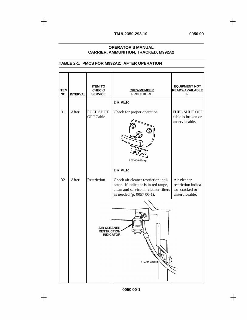
TM 9-2350-293-10 0050 00
0050 00-1
TABLE 2-1. PMCS FOR M992A2: AFTER OPERATION
ITEMNO. INTERVAL
ITEM TOCHECK/
SERVICECREWMEMBERPROCEDURE
EQUIPMENT NOTREADY/AVAILABLE
IF:
DRIVER
31 After FUEL SHUT Check for proper operation. FUEL SHUT OFFOFF Cable cable is broken or
unserviceable.
DRIVER
32 After Restriction Check air cleaner restriction indi- Air cleanercator. If indicator is in red range, restriction indica-clean and service air cleaner filters tor cracked oras needed (p. 0057 00-1). unserviceable.
OPERATOR'S MANUALCARRIER, AMMUNITION, TRACKED, M992A2

TABLE 2-1. PMCS FOR M992A2: AFTER OPERATION (continued) 0050 00
TM 9-2350-293-10
0050 00-2
ITEMNO. INTERVAL
ITEM TOCHECK/
SERVICECREWMEMBER
PROCEDURE
EQUIPMENT NOTREADY/AVAILABLE
IF:
CREWMEMBER
33 After Upper Rear Check upper rear door dump valveDoor Dump to make sure that it is closedValve (turned fully clockwise).
CREWMEMBER
34 After Lower Open lower rear door (p. 0027Rear 00-8). Operate handle severalDoor times to make sure there is no free
play and lock does not close with-out actuating it. If lock closes orthere is excessive free play inhandle, notify Unit maintenance.

TABLE 2-1. PMCS FOR M992A2: AFTER OPERATION (continued) 0050 00
TM 9-2350-293-10
0050 00-3
COMMANDER
a. Disassemble, clean, and lightlylubricate machine gun. PerformPMCS IAW TM 9-1005-213-10.
ITEMNO. INTERVAL
ITEM TOCHECK/
SERVICECREWMEMBERPROCEDURE
EQUIPMENT NOTREADY/AVAILABLE
IF:
CAUTION
Never pull back boltassembly with the safety on"S." The safety assemblywill be damaged.
b. Reassemble machine gun andcheck for ease of operation.
DRIVER
36 After Auxiliary Open APU front door and checkPower Unit APU engine oil level. Add oil to(APU) bring level up to full (F) mark onOil Level dipstick. Add or drain as needed.
35 After 0.50-Cal. M2 Check to see that machineMachine Gun gun is clear of ammunition
and barrel is free ofobstructions.
WARNING

DRIVER
37 After APU Fuel Turn MASTER switch and APU Any leak is found.Filters FUEL SHUT OFF switch to ON.
Drain primary fuel filter firstand then secondary fuel filter untilcontaminants are removed. TurnAPU FUEL SHUT OFF switch andMASTER switch to OFF. Inspectfuel lines and hoses for damage,leaks, and loose connections.
TABLE 2-1. PMCS FOR M992A2: AFTER OPERATION (continued) 0050 00
ITEMNO. INTERVAL
ITEM TOCHECK/
SERVICECREWMEMBER
PROCEDURE
TM 9-2350-293-10
0050 00-4
EQUIPMENT NOTREADY/AVAILABLE
IF:

DRIVER
38 After APU Engine Check to see that air passages areAir Passages free of dirt and debris. Inspect for
clogging in louvers in front andside doors. Open front of APUand inspect fan for dirt, debris, ordamage.
DRIVER
39 After Final Drive a. Inspect left and right final a. Any U-jointU-Joints drive U-joints for presence and quick-disconnectand Quick security of lacing wire on quick- bolt is loose,Disconnects disconnect bolts. missing, or not
laced.
b. Check final drives for oil leaks. b. Class III leakfound.
40 After Transmission Check oil level; level should beOil Level within the OPERATING RANGE
stamped on dipstick. Add oil(p. 0078 00-3) as required.
TABLE 2-1. PMCS FOR M992A2: AFTER OPERATION (continued) 0050 00
ITEMNO. INTERVAL
ITEM TOCHECK/
SERVICECREWMEMBERPROCEDURE
EQUIPMENT NOTREADY/AVAILABLE
IF:
TM 9-2350-293-10
0050 00-5

NOTE
New transmissions are deliv-ered with preservative PE-10-1.Until first scheduled oil change,maintain proper oil level byadding OE/HDO or OEA.
DRIVER
41 After Engine Oil NOTELevel
Make engine oil level check withvehicle on level ground ifpossible. Oil level will takeapproximately 20 minutes tostabilize in engine crankcase.After 20 minutes, check oil level;it should be within the L - Frange stamped on dipstick.
TABLE 2-1. PMCS FOR MODEL M992A2 (continued) 0050 00
ITEMNO. INTERVAL
ITEM TOCHECK/
SERVICECREWMEMBERPROCEDURE
EQUIPMENT NOTREADY/AVAILABLE
IF:
TM 9-2350-293-10
0050 00-6

CREWMEMBER
42 After Track Adjus- Check for bent or broken track Either track ad-ter Cylinder adjuster cylinder assemblies. juster cylinderAssemblies assembly is bent,
Track adjusters have reached their broken, or beyondmaximum extended limit at 3-1/2 maximum limits.inches (8.89 cm).
43 After Track Tension Perform same check as on p. 004900-18.
TABLE 2-1. PMCS FOR M992A2: AFTER OPERATION (continued) 0050 00
ITEMNO. INTERVAL
ITEM TOCHECK/
SERVICECREWMEMBER
PROCEDURE
EQUIPMENT NOTREADY/AVAILABLE
IF:
TM 9-2350-293-10
0050 00-7

DRIVER/CREWMEMBER44 After Sprocket
Wheels a. Check sprocket wheels for a. Any sprocketcracked, broken, or missing teeth, wheel tooth isloose or missing sprocket cap cracked, broken,screws and self-locking nuts, and or missing. Anyloose or missing sprocket hub to sprocket capfinal drive self-locking bolts. screws or self-
locking nuts aremissing or broken.Any sprocket hubto final drive self-locking nuts orself-locking boltsare missing orbroken.
TABLE 2-1. PMCS FOR M992A2: AFTER OPERATION (continued) 0050 00
ITEMNO. INTERVAL
ITEM TOCHECK/
SERVICECREWMEMBERPROCEDURE
EQUIPMENT NOTREADY/AVAILABLE
IF:
TM 9-2350-293-10
0050 00-8

44 After Sprocket NOTEWheels(continued) • Only two sprocket wheel teeth
have wear indicators.
• Sprocket wheel teeth wear faster on the inside. A tooth may be excessively worn, but still not show wear into wear mark.
b. Check sprocket wheel teeth for b. One or moreexcessive wear. Using a ruler, sprocket wheelmeasure from inside edge of tooth teeth worn intointo wear area. Then measure edge of wearedge distance from edge of tooth indicator, or oneto wear indicator. If the first or more sprocketmeasurement is equal to or greater wheel teeth show-than the second, sprocket wheel ing excessivewear is excessive. Notify Unit wear.maintenance.
TABLE 2-1. PMCS FOR M992A2: AFTER OPERATION (continued) 0050 00
ITEMNO. INTERVAL
ITEM TOCHECK/
SERVICECREWMEMBERPROCEDURE
EQUIPMENT NOTREADY/AVAILABLE
IF:
TM 9-2350-293-10
0050 00-9

DRIVER/CREWMEMBER
45 After Roadwheels a. Check to make sure mounting a. Two or moreand Idler nuts are secure. idler wheelWheels mounting nuts
missing. Threeor more road-wheel mountingnuts on same hubmissing.
b. Check for loss of rubber, pitting, b. Any missing,shrinking, and separation of rubber bent, warped, orfrom metal. cracked roadwheel
or idler wheel.Separation of 1inch (2.54 cm) ofrubber from sur-face around 3/4 ofroadwheel and/orchunking thatcauses metal-to-metal contactbetween road-wheel and track.
c. Check for elongation of mount- c. Mounting holesing holes. are elongated on
any wheel.
NOTE
Relief valves are located on backof roadwheel and idler hubs andshould be checked for slippage.
d. Check roadwheel hub forgrease seepage.
TABLE 2-1. PMCS FOR M992A2: AFTER OPERATION (continued) 0050 00
ITEMNO. INTERVAL
ITEM TOCHECK/
SERVICECREWMEMBER
PROCEDURE
EQUIPMENT NOTREADY/AVAILABLE
IF:
TM 9-2350-293-10
0050 00-10

TABLE 2-1. PMCS FOR M992A2: AFTER OPERATION (continued) 0050 00
ITEMNO. INTERVAL
ITEM TOCHECK/
SERVICECREWMEMBERPROCEDURE
EQUIPMENT NOTREADY/AVAILABLE
IF:
TM 9-2350-293-10
0050 00-11

TABLE 2-1. PMCS FOR M992A2: AFTER OPERATION (continued) 0050 00
TM 9-2350-293-10
0050 00-12
DRIVER/CREWMEMBER
WARNING
Check all hubs carefully. Hubsmay be hot. Failure to heedthis warning may result ininjury to personnel.
a. Check for overheated wheel a. Wheel hub ishubs. After operation, touch all overheating.hubs cautiously for noticeabletemperature difference betweencomponents. An overheated hubindicates a malfunction, inadequatelubrication, or damaged bearing.
NOTE
If shock absorber is operatingproperly, it should be warmerthan the hull area around it.
b. Check lower end of shock b. Shockabsorber cautiously, and check for absorber brokentemperature difference between or missing.hull area and shock absorber. Ifoverheating occurs, notify Unitmaintenance.
c. Turn shock absorber from side c. Shockto side. If shock absorber moves, absorberupper end is damaged. Notify Unit moves from sidemaintenance. to side.
ITEMNO. INTERVAL
ITEM TOCHECK/
SERVICECREWMEMBERPROCEDURE
EQUIPMENT NOTREADY/AVAILABLE
IF:
46 After Wheel Hubsand ShockAbsorbers

DRIVER/COMMANDER
47 After Track Shoes NOTEand Bushings
Worn bushings are very difficultto locate. They will cause trackpin to appear off-center. A trackshoe with a worn bushing mayhave protruding track pin andunusual gaps between twoadjacent shoes.
a. Check track shoes for damaged a. Any track shoetrack pins and any unusual or un- with worn bush-even gaps between adjacent track ing. Any bushingshoes, indicating worn bushings. deemed un-
serviceable. Anytrack shoe bent,cracked, or brok-en. Any track pinbent, broken, ormissing.
b. Check track shoe for damage, b. Any track shoeincluding cracked or broken shoe body bent, broken,body; bent, broken, or missing or cracked. Anycenter guides; and chunked or track pin broken,missing roadwheel pad rubber. bent, or missing.Report damaged track to Unitmaintenance. Replace worn ormissing track shoe pads and nuts(p. 0058 00-12).
TABLE 2-1. PMCS FOR M992A2: AFTER OPERATION (continued) 0050 00
ITEMNO. INTERVAL
ITEM TOCHECK/
SERVICECREWMEMBERPROCEDURE
EQUIPMENT NOTREADY/AVAILABLE
IF:
TM 9-2350-293-10
0050 00-13

TABLE 2-1. PMCS FOR M992A2: AFTER OPERATION (continued) 0050 00
TM 9-2350-293-10
0050 00-14
DRIVER/COMMANDER
48 After Track End Check for loose, missing, or worn Any missing orConnectors track end connectors and bolts, cracked track endand Center track center guides, track pads, and connectors, miss-Guides track shoes. ing center guides,
or missing bolts.DRIVER
ITEMNO. INTERVAL
ITEM TOCHECK/
SERVICECREWMEMBER
PROCEDURE
EQUIPMENT NOTREADY/AVAILABLE
IF:

49 After Torsion Bars Check for bent, broken, or missing Torsion bar orand Road- roadwheel arms and torsion bars. roadwheel arm iswheel Arms With crowbar, try to lift each road- bent, broken, or
wheel. If any roadwheel comes up missing.easily, you have a broken or miss-ing torsion bar. Report any brokenor missing torsion bars to Unitmaintenance.
TABLE 2-1. PMCS FOR M992A2: AFTER OPERATION (continued) 0050 00
ITEMNO. INTERVAL
ITEM TOCHECK/
SERVICECREWMEMBER
PROCEDURE
EQUIPMENT NOTREADY/AVAILABLE
IF:
TM 9-2350-293-10
0050 00-15/16 blank
END OF WORK PACKAGE


TM 9-2350-293-10
OPERATOR'S MANUALCARRIER, AMMUNITION, TRACKED, M992A2
51 Weekly Chemical DRIVER/CREWMEMBERAgentDetector Unit
50 Weekly Hydraulic With MASTER switch turned on,Fluid Level check hydraulic fluid level gage
to make sure needle is on F. Ifnecessary, add hydraulic oil(p. 0078 00-22) through remotefill cap to bring level up to F mark.
Service detector unit IAW TM3-6665-225-12. Replacereservoir fluid and change airfilter only as needed. PerformPMCS IAW TM 3-6665-225-12.
0051 00
ITEMNO. INTERVAL
ITEM TOCHECK/
SERVICECREWMEMBERPROCEDURE
EQUIPMENT NOTREADY/AVAILABLE
IF:
TABLE 2-1. PMCS FOR M992A2: WEEKLY AND MONTHLYCHECKS AND SERVICES (continued)
WARNING
NBC-contaminated filtersmust be handled usingadequate precautions andmust be disposed of bytrained personnel.
0051 00-1

TM 9-2350-293-10
52 Weekly Nuclear, a. Remove air inlet cover. WithBiological, MASTER switch turned to ON,or Chemical turn VFPS (NBC) power switch(NBC) to ON. Check motor for smoothSystem Air operation. Check air outlets forPurifier airflow. Inspect filter assembly
for dents, cracks, secure mount-ing, and missing parts.
b. Check operation of NBCheaters. Turn VFPS (NBC) powerswitch to ON. Turn air heateron and check to see that greenlight illuminates (p. 0030 00-21).
ITEMNO. INTERVAL
ITEM TOCHECK/
SERVICECREWMEMBERPROCEDURE
EQUIPMENT NOTREADY/AVAILABLE
IF:
TABLE 2-1. PMCS FOR M992A2:WEEKLY AND MONTHLY CHECKS AND SERVICES (continued) 0051 00
0051 00-2

TM 9-2350-293-10
DRIVER/CREWMEMBER
53 Weekly Lights a. Check driving lights by turningon driving lights switch (p. 003300-13). Depress high-beam switchto make sure lights operate prop-erly on high and low beams.
b. Check HI BEAM indicator lightand MASTER WARNING in-dicator light.
NOTE
Driver will turn on lights andcrewmember will check foroperation.
c. Check stoplights and taillightsto see that they operate properly.Make sure lights brighten duringbraking.
d. Check blackout drive lights:
• Set main light switch lever to BO DRIVE.
e. Check dome lights.
ITEMNO. INTERVAL
ITEM TOCHECK/
SERVICECREWMEMBERPROCEDURE
EQUIPMENT NOTREADY/AVAILABLE
IF:
TABLE 2-1. PMCS FOR M992A2:WEEKLY AND MONTHLY CHECKS AND SERVICES (continued) 0051 00
0051 00-3

TM 9-2350-293-10
DRIVER
54 Weekly Bilge Pump CAUTION
• Do not run bilge pump formore than one minute dry,or more than 15 minuteswet without starting engine.
• Do not ford if bilge pump isinoperative or missing.
Check operation of bilge pump.If pump is dry, feel air outlet whenpump is running.
DRIVER
55 Weekly Batteries WARNING
Do not smoke, use openflame, make sparks, orcreate other ignitionsources around batteries.If a battery is giving offgas, it can explode andcause injury to personnel.
ITEMNO. INTERVAL
ITEM TOCHECK/
SERVICECREWMEMBERPROCEDURE
EQUIPMENT NOTREADY/AVAILABLE
IF:
TABLE 2-1. PMCS FOR M992A2:WEEKLY AND MONTHLY CHECKS AND SERVICES (continued) 0051 00
a. Check electrolyte level. Elec- A battery istrolyte level must be about 1/2 missing or un-inch over top of plates. Some serviceable orbatteries have lips inside, or in- engine will notdicators, to show where the crank. Any cableelectrolyte level should be. If or terminal iselectrolyte is low, add distilled loose. Anywater to bring electrolyte to proper battery is brokenlevel. If water is added or fluid or cracked.
0051 00-4

TM 9-2350-293-10
is boiling and the outside temper-ature drops to near or below thefreezing point, run the vehicleengine for 15 minutes to allow thewater to mix the electrolyte.
ITEMNO. INTERVAL
ITEM TOCHECK/
SERVICECREWMEMBERPROCEDURE
EQUIPMENT NOTREADY/AVAILABLE
IF:
TABLE 2-1. PMCS FOR M992A2:WEEKLY AND MONTHLY CHECKS AND SERVICES (continued) 0051 00
b. Make sure the vent holes oncaps are open to permit escape ofgases; also, make sure caps arescrewed on tightly.
0051 00-5

TM 9-2350-293-10
TABLE 2-1. PMCS FOR M992A2:WEEKLY AND MONTHLY CHECKS AND SERVICES (continued) 0051 00
d. Make sure a light coat of GAAgrease is applied and covers allterminals and posts after clampingdown battery. Keep grease frombetween posts and terminals.
55 Weekly Batteries c. Inspect terminals, posts, clamps,(continued) cables, and battery hold-downs and
battery boxes for corrosion. Ifcorrosion is present, have Unitmaintenance clean and coat allclamps, hold-downs, and batteryboxes, except posts and terminals.
CAUTION
To reduce battery damage,do not remove batteriesfrom equipment batteryboxes, except duringscheduled maintenance orduring battery replacement.Battery replacement will beperformed only by Unitmaintenance personnel.
ITEMNO. INTERVAL
ITEM TOCHECK/
SERVICECREWMEMBERPROCEDURE
EQUIPMENT NOTREADY/AVAILABLE
IF:
0051 00-6

TM 9-2350-293-10
e. Make sure rubber grommets arein place to keep cables from beingcut on the edge of holes.
f. Further battery information thatpertains to this subject matter canbe found in TM 9-6140-200-14.
DRIVER
56 Weekly Front and Check front and rear slave cableRear Slave receptacle connectors and capsCable for damage, burned-out condition,Receptacle and corrosion (two locations).Connectors
ITEMNO. INTERVAL
ITEM TOCHECK/
SERVICECREWMEMBERPROCEDURE
EQUIPMENT NOTREADY/AVAILABLE
IF:
TABLE 2-1. PMCS FOR M992A2:WEEKLY AND MONTHLY CHECKS AND SERVICES (continued) 0051 00
0051 00-7

TM 9-2350-293-10
57 Weekly Doors, Check hatch and door seals for Driver's orHatches, looseness, tears, or deterioration. commander'sand Latches Make sure hatches and doors lock hatch door will
securely in both open and closed not lock, open,positions. and/or close.
Rear door will notopen or close or ismisaligned. Anyhatch or door ismissing.
DRIVER
58 Weekly Tow Pintle Check tow pintle for proper opera-tion. Pull back spring arm. Makesure pintle opens. Close pintle.Make sure pintle locks close. In-spect pintle for loose mountingscrews.
ITEMNO. INTERVAL
ITEM TOCHECK/
SERVICECREWMEMBERPROCEDURE
EQUIPMENT NOTREADY/AVAILABLE
IF:
TABLE 2-1. PMCS FOR M992A2:WEEKLY AND MONTHLY CHECKS AND SERVICES (continued) 0051 00
0051 00-8
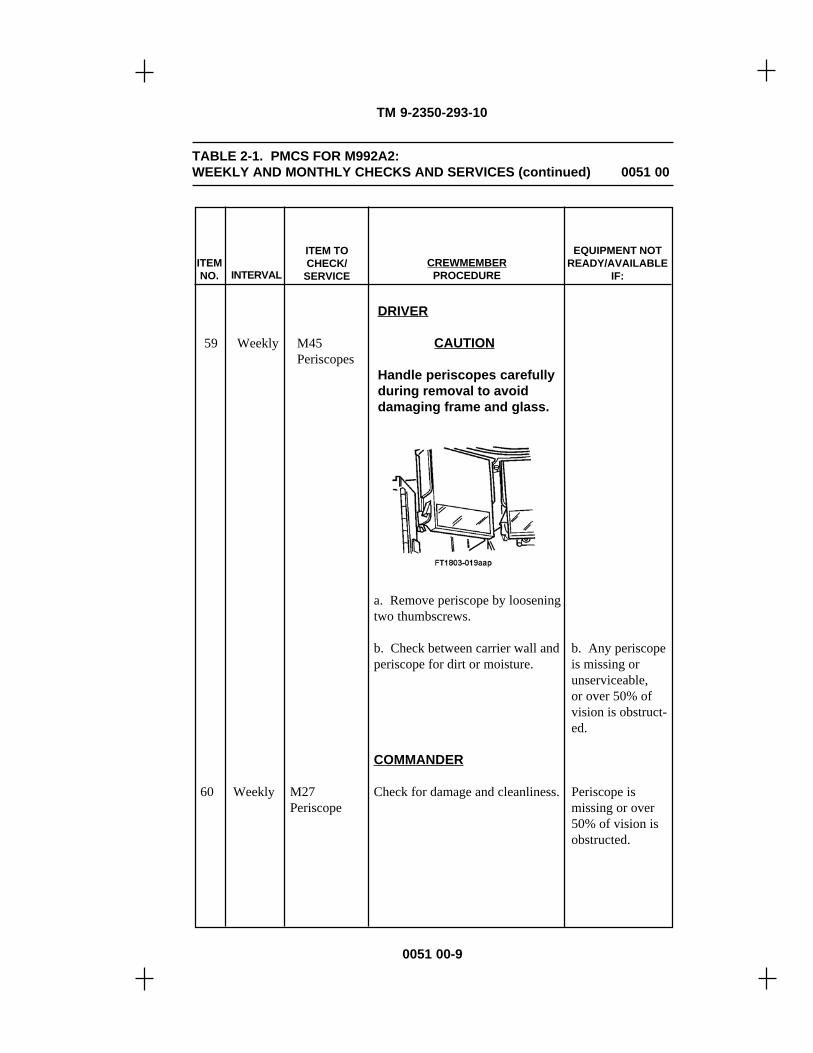
TM 9-2350-293-10
DRIVER
59 Weekly M45 CAUTIONPeriscopes
Handle periscopes carefullyduring removal to avoiddamaging frame and glass.
a. Remove periscope by looseningtwo thumbscrews.
b. Check between carrier wall and b. Any periscopeperiscope for dirt or moisture. is missing or
unserviceable,or over 50% ofvision is obstruct-ed.
COMMANDER
60 Weekly M27 Check for damage and cleanliness. Periscope isPeriscope missing or over
50% of vision isobstructed.
ITEMNO. INTERVAL
ITEM TOCHECK/
SERVICECREWMEMBERPROCEDURE
EQUIPMENT NOTREADY/AVAILABLE
IF:
TABLE 2-1. PMCS FOR M992A2:WEEKLY AND MONTHLY CHECKS AND SERVICES (continued) 0051 00
0051 00-9

TM 9-2350-293-10
TABLE 2-1. PMCS FOR M992A2:WEEKLY AND MONTHLY CHECKS AND SERVICES (continued) 0051 00
61 Weekly PersonnelHeater
a. Start and operate heater(p. 0033 00-2 or 0033 00-3). Ifheater does not start, notify Unitmaintenance.
b. Check crew/driver duct outletsfor steady warm-air output. Ifthere is no warm-air output, shutoff heater (p. 0033 00-3 or 003300-4) and notify Unitmaintenance.
WARNING
• If heater operates im-properly, fuel may over-flow, causing danger offire or explosion.
• Be alert during heateroperation for exhaustodors or signs of ex-posure to carbon mon-oxide. Carbon monoxidecan kill you. If yoususpect that carbonmonoxide is present, shutoff heater and ventilatevehicle.
• Explosive/flammablematerials are a fire hazard.Do not store aerosol cans,solvents, fuel, etc.,anywhere inside vehicle.Stow ammunition andpowder in authorizedstowage racks.
ITEMNO. INTERVAL
ITEM TOCHECK/
SERVICECREWMEMBERPROCEDURE
EQUIPMENT NOTREADY/AVAILABLE
IF:
0051 00-10

TM 9-2350-293-10
TABLE 2-1. PMCS FOR M992A2:WEEKLY AND MONTHLY CHECKS AND SERVICES (continued) 0051 00
c. Drain fuel filter.
(1) Remove right front canistercompartment shield (p. 006700-1).
(2) Place suitable containerunder filter and push drainbutton to drain water fromfilter.
d. Check personnel heater for d. Any fuel leaksigns of damage and fuel leaks. found.
e. Check all heater air outlets forobstructions.
f. Check all tubes, fuel filter, fuel f. Any fuel leakpump, and hoses for air and fuel found.leaks by smelling and looking athull floor under heater area.
ITEMNO. INTERVAL
ITEM TOCHECK/
SERVICECREWMEMBERPROCEDURE
EQUIPMENT NOTREADY/AVAILABLE
IF:
0051 00-11
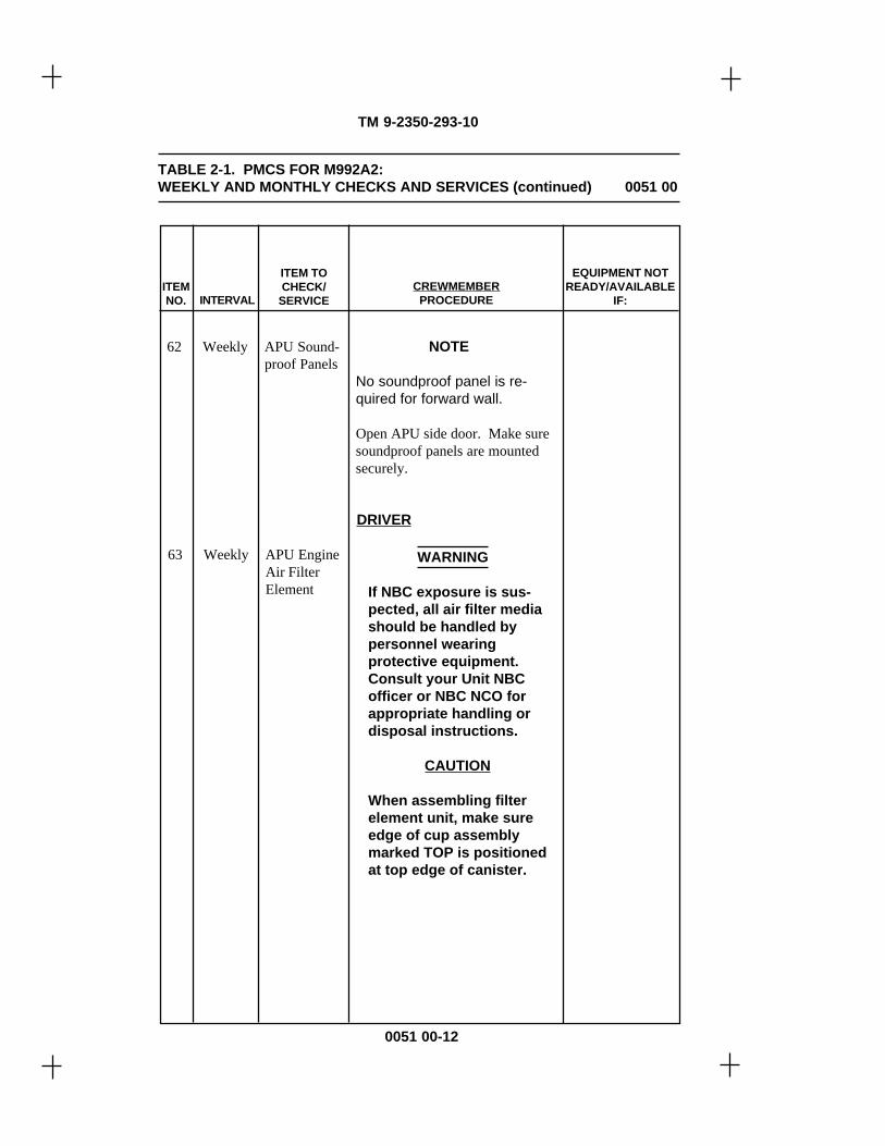
TM 9-2350-293-10
62 Weekly APU Sound- NOTEproof Panels
No soundproof panel is re-quired for forward wall.
Open APU side door. Make suresoundproof panels are mountedsecurely.
DRIVER
63 Weekly APU EngineAir FilterElement
WARNING
If NBC exposure is sus-pected, all air filter mediashould be handled bypersonnel wearingprotective equipment.Consult your Unit NBCofficer or NBC NCO forappropriate handling ordisposal instructions.
CAUTION
When assembling filterelement unit, make sureedge of cup assemblymarked TOP is positionedat top edge of canister.
ITEMNO. INTERVAL
ITEM TOCHECK/
SERVICECREWMEMBERPROCEDURE
EQUIPMENT NOTREADY/AVAILABLE
IF:
TABLE 2-1. PMCS FOR M992A2:WEEKLY AND MONTHLY CHECKS AND SERVICES (continued) 0051 00
0051 00-12

TM 9-2350-293-10
Loosen filter-cap clamp eyebolt.Remove cup assembly. Removefilter wingnut and slide filter ele-ment from canister. Hold gasketend of filter element to light source.If light is not visible through ele-ment, service the element. Removerubber baffle assembly from insideof cover. Empty dust from coverand wipe inside of cover with aclean damp cloth. Install baffleassembly in cup assembly.Reassemble filter element unit.Do not operate if filter element isclogged, dirty, or missing.
ITEMNO. INTERVAL
ITEM TOCHECK/
SERVICECREWMEMBERPROCEDURE
EQUIPMENT NOTREADY/AVAILABLE
IF:
TABLE 2-1. PMCS FOR M992A2:WEEKLY AND MONTHLY CHECKS AND SERVICES (continued) 0051 00
0051 00-13

TM 9-2350-293-10
64 Weekly APU Genera- Remove filter assembly wingnut,tor Air Filter washer, and weather hood. Empty
dust from weather hood and wipeinside of cover with clean damprag. If filter assembly precleanerand element are clogged or dirty,service precleaner and filter ele-ment (p. 0062 00-4). Reassemblefilter assembly. Do not operate iffilter element is clogged, dirty, ormissing.
COMMANDER
65 Weekly Fatigue Inspect fatigue (floor) mats in(Floor) Mats crew compartment for tears.
ITEMNO. INTERVAL
ITEM TOCHECK/
SERVICECREWMEMBERPROCEDURE
EQUIPMENT NOTREADY/AVAILABLE
IF:
TABLE 2-1. PMCS FOR M992A2:WEEKLY AND MONTHLY CHECKS AND SERVICES (continued) 0051 00
0051 00-14

TM 9-2350-293-10
COMMANDER/CREWMEMBERS
66 Monthly Stowage Inspect all internal and externalAreas stowage boxes, stops, brackets,
decals, shelves, nets, and restraintsfor damage. This is the duty ofevery crewmember. Notify Unitmaintenance if any damage exists.
COMMANDER/CREWMEMBERS
67 Monthly Projectile Remove projectile rack sections Rack sectionRack from against front wall of crew/ missing. SafetySections cargo compartment (p. 0032 00-5). wire broken,
Inspect rack restraints for broken loose, or missingsafety wires and loose or missing bolts. Rack inter-bolts. Check to see that rack locking rods bent,interlocking rods are not bent and cracked, or miss-are securely installed. Check to ing. Setscrew forsee that setscrew at each locking locking handlehandle pivot is present and secure. missing. LockingInspect locking bars for security. bar will not lock.
ITEMNO. INTERVAL
ITEM TOCHECK/
SERVICECREWMEMBERPROCEDURE
EQUIPMENT NOTREADY/AVAILABLE
IF:
TABLE 2-1. PMCS FOR M992A2:WEEKLY AND MONTHLY CHECKS AND SERVICES (continued) 0051 00
0051 00-15

TM 9-2350-293-10
DRIVER/COMMANDER
68 Monthly Engine Air a. Check air filters (p. 0057 00-1).Cleaner
b. Check to see that access door b. Air cleanercloses and latches securely. doors, filterLocking handles must be properly elements, or hosesset for summer or winter. are missing. Air
cleaner doorswill not open orclose properly.Any hose or filteris torn or has ahole.
c. Blow filters out with low- c. Any evidencepressure air. Wash filters with of leakage of un-warm water if needed. If washed, filtered air intoallow filters to completely dry intake system.before reinstallation.
d. Check air filter doors, gaskets, d. Any air filterand hoses. hose, door, or
gasket is missingor damaged.
e. Set engine air cleaner systemfor summer or winter position.(p. 0000 00-xx).
ITEMNO. INTERVAL
ITEM TOCHECK/
SERVICECREWMEMBERPROCEDURE
EQUIPMENT NOTREADY/AVAILABLE
IF:
TABLE 2-1. PMCS FOR M992A2:WEEKLY AND MONTHLY CHECKS AND SERVICES (continued) 0051 00
0051 00-16

TM 9-2350-293-10
TABLE 2-1. PMCS FOR M992A2:WEEKLY AND MONTHLY CHECKS AND SERVICES (continued) 0051 00
DRIVER/COMMANDER
69 Monthly Fuel Strainer Service fuel strainer and fill capand Fill Cap (p. 0057 00-1).
70 Monthly Final Drive Remove level-check plug. Oil Any Class IIILevel Check should be level with bottom of leak exists.
opening. If not, add OE/HDO(refer to p. 0079 00-5) until oilflows from level-check plug open-ing. Clean and reinstall plug.
ITEMNO. INTERVAL
ITEM TOCHECK/
SERVICECREWMEMBERPROCEDURE
EQUIPMENT NOTREADY/AVAILABLE
IF:
END OF WORK PACKAGE
0051 00-17/18 blank

TM 9-2350-293-10

0052 00
OPERATOR'S MANUALCARRIER, AMMUNITION, TRACKED, M992A2
ENGINE COOLING SYSTEM MAINTENANCE
THIS WORK PACKAGE COVERS:Adding Coolant, Faulty Cooling System, and Draining Coolant
INITIAL SETUP:Maintenance Level
Operator/Crew
0052 00-1
ADDING COOLANT
WARNING
Steam can cause serious burns. NEVER remove radiator cap on anoverheated engine until engine has cooled.
NOTE
Overheating is caused by a faulty cooling system or low coolantlevel. Proper maintenance of cooling system will help preventoverheating.
1. Park vehicle on level ground. Lower rpm below cruising speed on an overheated engineuntil temperature drops below 185°F. If temperature continues to rise, shut downcompletely and allow 10 minutes for engine to cool before adding coolant.
TM 9-2350-293-10
2. Open radiator cap access cover (1). Place a ragover radiator cap (2), then slowly loosen cap (2) torelieve steam and pressure. When steam subsides,remove cap (2).
3. Start engine and idle. Add coolant to top of fillerneck and replace cap (2).
4. Run engine for one minute longer to eliminate anyair locks; recheck coolant level and add coolant ifnecessary.
FAULTY COOLING SYSTEM
If radiator is clogged or dirty, notify Unit maintenance.

0052 00-2
DRAINING COOLANT
1. Monitor engine temperature on ENGINE WATER TEMP gage, and allow engine to coolto below 185°F.
2. Place vehicle on an incline, nose down, to facilitate coolant draining.
3. Remove three screws (5) and washers (4) and access cover (1) from bottom of vehicle.
4. Using a 9/16-inch socket head screw key, remove coolant drain plug (3) from radiator.Drain coolant into suitable container.
5. Slowly open valve (2).
6. Slowly remove radiator cap from radiator.
7. Close valve (2), replace plug (3) in radiator, and refill radiator with coolant.
8. Place vehicle on level ground and recheck coolant level.
9. Install access cover (1) on bottom of vehicle using three screws (5) and washers (4).
ENGINE COOLING SYSTEM MAINTENANCE (continued) 0052 00
COOLANT TEMPERATURE RANGES
-65°F to -40°F ................ Arctic-type antifreeze (Item 2, p. 0077 00-2)-40°F to +80°F ............... Antifreeze (Item 3 or 4, p. 0077 00-2)Above +80°F ................. Corrosion resistant coating (22-1/2 oz per vehicle) (Item 14,
p. 0077 00-5)
END OF WORK PACKAGE
TM 9-2350-293-10

TM 9-2350-293-10 0053 00
OPERATOR'S MANUALCARRIER, AMMUNITION, TRACKED, M992A2
SERVICING OF FUEL SYSTEM
INITIAL SETUP:Maintenance Level
Operator/Crew
0053 00-1
WARNING
Diesel fuel is FLAMMABLE. DO NOT smoke in vicinity while performingservicing operations.
1. Open two drain cocks (1 and 2) on primary and secondary fuel filters to removewater and dirt. Place container under drain cocks.
2. When clear fuel is visible, close two drain cocks.
NOTE
• After primary and secondary fuel filters have been drained, purge airfrom fuel system by turning on FUEL PRIME switch for one minuteprior to starting engine.
• Fuel tanks hold 135 gallons of fuel. Before draining, provide enoughcontainer capacity to hold fuel to be drained.

TM 9-2350-293-10
0053 00-2
SERVICING OF FUEL SYSTEM (continued) 0053 00
3. When necessary, remove water and dirt from fuel tanks as follows:
a. Remove three screws (5) and washers (6) and access cover (4) from bottom of vehicle.
b. Using adjustable wrench, remove fuel tank plug (3) from fuel tank drain.
c. When clear fuel is visible, replace fuel tank plug (3) in fuel tank drain.
d. Install access cover (4) on bottom of vehicle using three screws (5) and washers (6).
NOTE
After operation, keep fuel tanks full to minimize condensation.
END OF WORK PACKAGE

0054 00
OPERATOR'S MANUALCARRIER, AMMUNITION, TRACKED, M992A2
REFUELING
INITIAL SETUP:Maintenance Level
Operator/Crew
0054 00-1/2 blank
WARNING
Diesel fuel is FLAMMABLE. DO NOT smoke within 50 feet of vehiclewhile refueling.
1. Shut off engine.
2. Open fuel cap access door (1).
3. Clean any debris from compartment andaround fuel cap prior to removing fuel cap.
4. Remove fuel cap slowly. Make sure fuelstrainer is properly placed in mouth of fillerneck.
NOTE
Do not lay fuel hose acrossvehicle.
5. Fill to a level six inches below top of fillerneck.
6. Replace fuel cap and close access door (1).
END OF WORK PACKAGE
TM 9-2350-293-10


TM 9-2350-293-10 0055 00
OPERATOR'S MANUALCARRIER, AMMUNITION, TRACKED, M992A2
FUEL FILL STRAINER AND FILL CAP MAINTENANCE
INITIAL SETUP:Maintenance Level
Operator/Crew
0055 00-1
1. Using hinged socket wrench handle and 9/16-inch socket, remove eight screws (5),lockwashers (4), and washers (3) and access cover (2) from hull.
2. Unscrew fill cap (1) from fuel fill strainer (6).
3. Make sure fill cap (1) is securely chained to strainer (6). If chain is damaged, notify Unitmaintenance.
WARNING
Diesel fuel is flammable. Do not perform this procedure near fire, flame,or sparks. Injury or death to personnel could result.
4. Pull strainer (6) from access opening.
5. Check strainer (6) for rips, excessive clogging, or other unserviceable conditions. Ifstrainer (6) is unserviceable, notify Unit maintenance.

TM 9-2350-293-10
0055 00-2
WARNING
Drycleaning solvent P-D-680 is toxic and flammable. Always wearprotective goggles and gloves, and use only in a well-ventilated area.Avoid contact with skin, eyes, and clothes, and DO NOT breathe vapors.DO NOT use near open flame or excessive heat.
6. Remove breather cap (7) from fill cap (1). Clean breather cap (7) with drycleaning solvent(Item 17, p. 0077 00-3).
7. Apply thin coating of grease (Item 24, p. 0077 00-4) to mating surfaces of breather cap(7) and fill cap (1). Install breather cap (7) in fill cap (1).
8. Install strainer (6) in access opening. Install fill cap (1) on strainer (6).
FUEL FILL STRAINER AND FILL CAP MAINTENANCE (continued) 0055 00
NOTE
Notify Unit maintenance if lockwashers are unserviceable.
9. Using hinged socket wrench handle and 9/16-inch socket, install access cover (2) on hullwith eight screws (5), lockwashers (4), and washers (3).
END OF WORK PACKAGE

TM 9-2350-293-10 0056 00
OPERATOR'S MANUALCARRIER, AMMUNITION, TRACKED, M992A2
SERVICING OF BATTERIES
THIS WORK PACKAGE COVERS:Loose Connections, Electrolyte Level, Corrosion, and Unserviceable Batteries
INITIAL SETUP:Maintenance Level
Operator/Crew
0056 00-1
WARNING
Lead-acid batteries can explode. Do not smoke, have open flames, ormake sparks around a battery, especially if the caps are off. If a batteryis gassing, it can explode and cause injury to personnel.
LOOSE CONNECTIONS
1. Connectors should be tight and all the way down on battery posts (refer to TM 9-6140-200-14).
2. Battery hold-downs should be tight, but not so tight as to damage battery case.
3. If bolt threads are corroded so as to prevent a tight hold, notify Unit maintenance forreplacement.
4. If cables or terminals are loose or broken, notify Unit maintenance.

TM 9-2350-293-10
0056 00-2
SERVICING OF BATTERIES (continued) 0056 00
ELECTROLYTE LEVEL
1. Clean off battery caps before removing. Do not allow dirt or foreign matter to get intobattery cells.
2. To allow gases to escape from cells, keep vent holes in battery caps clean.
3. Electrolyte level must not drop below top of battery plates. If this condition exists, fillwith distilled water to cover plates.
CORROSION
WARNING
Battery corrosion is an acid and will eat holes in your clothing or burnyour skin. Wash any acid off skin immediately.
1. Corrosion tends to build up on battery posts, terminals, and cables and may damagecables and terminals. If corrosion is found, notify Unit maintenance.
NOTE
Make sure battery caps are tight and no cracks are visible in batterycase.
2. Clean top of battery with a damp cloth and wipe dry.
UNSERVICEABLE BATTERIES
CAUTION
Complete discharge of batteries will lessen battery life and, in freezingweather, will burst battery case. Avoid running batteries down.
If batteries fail, notify Unit maintenance (refer to TM 9-6140-200-14).
END OF WORK PACKAGE

0057 00
OPERATOR'S MANUALCARRIER, AMMUNITION, TRACKED, M992A2
AIR CLEANER MAINTENANCE
INITIAL SETUP:Maintenance Level
Operator/Crew
0057 00-1
WARNING
If NBC exposure is suspected, all air filter media will be handled bypersonnel wearing full NBC protective equipment. Consult your unitNBC officer or NBC NCO for appropriate handling or disposal instructions.
Depending on conditions, air cleaner must be removed periodically for cleaning. Loss inengine power, an overheating engine, or excessive black exhaust may indicate need for morefrequent cleaning. If yellow sleeve of air cleaner restriction indicator has climbed into redzone, air cleaner is restricted and air filters must be checked.
1. Park vehicle on level ground.
2. Shut off engine (p. 0018 00-1).
3. Remove all projectiles from right projectile rackassembly (p. 0032 00-4).
4. Remove canisters from stowage box on top of rightprojectile rack assembly.
5. Move right projectile rack assembly toward rear ofvehicle (p. 0032 00-5).
6. Remove right access door (3) by pulling down locking latch (2) and lifting door.
CAUTION
Do not pull up left door too far as this will cause binding and damage to doorwhen removing.
7. Remove left access door (1) by pulling down locking latch (4), pulling door up slightly,and sliding door to right.
TM 9-2350-293-10

0057 00-2
AIR CLEANER MAINTENANCE (continued) 0057 00
8. Pull down locking handles (5). Push two air filters (6) in, lift,and pull out from air cleaner box.
WARNING
Compressed air used for cleaning purposesshould not exceed 30 psi (206.8 kPa). Usecompressed air only with effective chip-guardingand personal protective equipment (e.g., goggles/shield, gloves). Failure to do this may result ininjury to personnel.
9. Clean air filters (6) with compressed air. (Emergency clean byrapping bottom or sides of air filter against flat surface. Do notstrike open edge or sealing edge.)
10. Clean air filter compartments with damp rags (Item 43, p. 007700-6).
11. Clean air duct into air filter box with damp rags (Item 43, p.0077 00-6) as far as possible.
12. Check seal (7) on right and left access doors (3 and 1) fordamage or unservicable condition. If seal is damaged or inunservicable condition, notify Unit maintenance.
13. Replace air filters (6); align with outlet gaskets to assureproper sealing, and secure locking handles (5).
TM 9-2350-293-10

14. Slide right and left access doors (3 and 1) on air cleaner. Secure doors by pulling lockinglatches (4 and 2) down and then up.
15. Reset air cleaner restriction indicator (8) by pushing up on reset button (located onbottom of cylinder).
16. Start engine (p. 0012 00-1). If yellow sleeve in indicator (8) climbs into red zone, notifyUnit maintenance.
17. Install right projectile rack assembly (p. 0032 00-9).
0057 00-3/4 blank
AIR CLEANER MAINTENANCE (continued) 0057 00
TM 9-2350-293-10
END OF WORK PACKAGE


TM 9-2350-293-10 0058 00
OPERATOR'S MANUALCARRIER, AMMUNITION, TRACKED, M992A2
TRACK MAINTENANCE
THIS WORK PACK COVERS:Checking Track Tension, Increasing Track Tension, Decreasing Track Tension,Disconnecting Track, Installing Track, Connecting Track, Removing Track Shoe,Removing Track Shoe from Stowage, Stowing Track Shoe, Installing Track Shoe,Removing Track Shoe Pads, and Installing Track Shoe Pads
INITIAL SETUP:Maintenance Level Personnel Required
Operator/Crew Two
0058 00-1
CHECKING TRACK TENSION
1. Move vehicle forward and backward severaltimes on level ground, stopping withoutapplying brakes.
2. Measure distance from top of thirdroadwheel (third from drive sprocket) totrack. If distance is more than 3/8 inch(0.95 cm) or less than 1/4 inch (0.64 cm),track tension needs adjustment.
INCREASING TRACK TENSION
Pump grease into clean fitting (2) on track adjuster (1) until correct tension is obtained.
CAUTION
When increasing track tension, donot let track adjuster extend beyond3-1/2 inches (8.89 cm) or adjuster willbind in extended position and willrequire force to collapse.
NOTE
If track sag cannot be taken up, decrease track tension, remove trackshoe, and adjust.

TM 9-2350-293-10
DECREASING TRACK TENSION
WARNING
Lubricant is under high pressure.Loosen bleed plug slowly to avoidinjury to personnel.
TRACK MAINTENANCE (continued) 0058 00
0058 00-2
Open bleed plug (1) on track adjuster and reduce pressure until tension is adjusted. Tightenplug (1) and wipe away excess grease.
DISCONNECTING TRACK
NOTE
At least two people are required to disconnect and connect track.
1. Position track disconnection point midway between No. 7 roadwheel (5) and idler wheel(1).
2. Shut off vehicle engine (p. 0018 00-1 ), and block track with logs or rocks. Do not setparking brake.
3. Decrease track tension.
4. Using 3/4-inch drive socket wrench and1-1/8 inch socket, remove two bolts (3)from two end connectors (2) on trackshoe (4).

TM 9-2350-293-10
0058 00-3
TRACK MAINTENANCE (continued) 0058 00
DISCONNECTING TRACK (continued)
5. Install straight pin (6) in end connector puller (7). Install end connector puller (7) throughbolt hole in end connector (2). Puller must rest flat against end connector (2), and straightpin (6) must engage bolt hole on both sides of end connector (2) so bolts of end connectorpuller (7) engage track link pins (10). Tighten or loosen straight pin (6) until endconnector puller (7) is properly adjusted.
CAUTION
• Tighten bolts on end connector puller evenly, so end connector ispulled evenly off track link pins. Failure to do this can result in damageto puller and track link pins.
• When tapping end connector puller with hammer, strike bolts squarelyto avoid mushrooming the heads of bolts and damaging puller.
NOTE
To help loosen end connectors, tap bolts of end connector puller withhammer while moving or removing end connector.
6. Using end connector puller (7), 3/4-inch drive, socket wrench, and 1-1/2 inch socket,move end connector (2) about 1 inch away from track shoe (4). If bolts on end connectorpuller (7) bind, tap end connector puller bolts (8) with hammer.
7. Install track connecting fixture (9) on two track link pins (10).

TM 9-2350-293-10
TRACK MAINTENANCE (continued) 0058 00
DISCONNECTING TRACK (continued)
8. Using end connector puller (7), remove end connector (2) from two track link pins (10).If end connector (2) becomes cocked during removal, remove end connector puller (7)and tap end connector (2) with hammer until end connector (2) is straight on track linkpins (10). Reinstall end connector puller (7), and continue to remove end connector (2).
9. Repeat steps 5 through 8 on end connector (2) on inside of track.
WARNING
Release tension on track connecting fixtures evenly. Track is undertension and can move suddenly, causing severe injury to personnel.
10. Remove two track connecting fixtures (9) from four track link pins (10).
INSTALLING TRACK
0058 00-4
1. Lay out track (80 shoes per side) in front ofvehicle in straight line directly ahead of, andtouching, first roadwheel.
2. Start engine ( p. 0012 00-1), and slowly driveonto track to point where enough track shoesto cover drive sprocket extend past centerline of first roadwheel.
3. Stop engine (p. 0018 00-1); leave parkingbrake off.

TM 9-2350-293-10
TRACK MAINTENANCE (continued) 0058 00
INSTALLING TRACK (continued)
4. Block opposite track with blocks.
5. Place an end connector (1) on end of track. Using crowbar, lift end of track over drivesprocket until end connectors (1) mesh with drive sprocket.
6. Start engine (p. 0012 00-1); remove blocks from track. Place shift lever in R1. Movevehicle back slowly, allowing track to rest on roadwheels and lifting up on end of trackto prevent it from getting caught between roadwheels.
7. Stop engine when two track connecting fixtures (3) can be connected to two track linkpins (2) on both sides of track. Connect track.
0058 00-5

TM 9-2350-293-10
TRACK MAINTENANCE (continued) 0058 00
CONNECTING TRACK
WARNING
Track is very heavy. Keep hands and feet from beneath track while it isbeing lifted.
1. Using crowbar, lift track end (1) until it is close enough to other end of track that two trackconnecting fixtures (2) can be installed.
2. Install two track connecting fixtures (2) on track, and tighten until one end connector(4) will fit over two track link pins (3). If necessary, reposition track connecting fixtures(2) (one at a time) as shown.
NOTE
Track can be maneuvered by lifting with crowbar or pushing againstinside of track to bow it out.
3. Maneuver track until end connector (4) can be installed over two track link pins (3) oninside of track. Tap end connector (4) with hammer to install over two track link pins (3).
0058 00-6
4. Install one end connector (4) on two track link pins (3) on outside of track.
5. Remove two track connecting fixtures (2) and logs or rocks from track.
6. Tap two end connectors (4) with hammer to seat end connectors (4) against track.

TM 9-2350-293-10
0058 00-7
CONNECTING TRACK (continued)
7. Install two bolts (5) in two end connectors(4).
8. Adjust track tension (pp. 0058 00-1 and0058 00-2).
9. Mark replaced end connectors (4).
10. Drive vehicle at a speed not to exceed 10miles per hour for a short distance,alternating right and left steers.
TRACK MAINTENANCE (continued) 0058 00
11. Stop vehicle and visually inspect for any end connectors that may have shifted. If anyend connectors have shifted, reposition. Tighten any bolts (5) that have been repositioned.Notify Unit maintenance to torque bolts between 380 and 420 lb-ft (518 and 570 N•m)wet at earliest opportunity.
NOTE
• Notify Unit maintenance to retorque end connector bolts after 50miles.
• If track is new, remove one track shoe after 50 miles.
REMOVING TRACK SHOE
NOTE
• At least two persons are required to replace a track shoe.
• If available, use penetrating oil on bolts on track shoe.
1. Position track shoe (3) to be removed midwaybetween No. 7 roadwheel (1) and idler wheel(2).
2. Shut off vehicle engine (p. 0018 00-1), andblock track with blocks. Do not set parkingbrake.

TM 9-2350-293-10
REMOVING TRACK SHOE (continued)
WARNING
Lubricant is under high pressure. Loosen bleed plug slowly to avoidinjury to personnel.
3. Decrease track tension (p. 0058 00-2).
4. Using 3/4-inch drive socket wrench and 1-1/8 inch socket, remove two bolts (9) fromtwo end connectors (8) on track shoe (3).
5. Install straight pin (4) in end connector puller (5). Install end connector puller (5)through bolt hole in end connector (8). Puller must rest flat on end connector (8), andstraight pin (4) must engage bolt hole on both sides of end connector (8) so end connectorpuller bolts (6) engage track link pins (7). Tighten or loosen straight pin (4) until endconnector puller (5) is properly adjusted.
TRACK MAINTENANCE (continued) 0058 00
0058 00-8
CAUTION
• Tighten bolts on end connector puller evenly, so end connector ispulled evenly off track link pins. Failure to do this can lead to damageto puller and track link pins.
• When tapping end connector puller with hammer, strike bolts squarelyto avoid mushrooming the heads of bolts and damaging puller.
NOTE
To help loosen end connectors, tap bolts of end connector puller withhammer while moving or removing end connector.
6. Using end connector puller (5), 3/4-inch drive socket wrench, and 1-1/2 inch socket,move end connector (8) about 1 inch away from track shoe (3). If bolts on end connectorpuller (5) bind, tap end connector puller bolts (6) with hammer.

TM 9-2350-293-10
TRACK MAINTENANCE (continued) 0058 00
0058 00-9
REMOVING TRACK SHOE (continued)
7. Install track connecting fixture (10) on two track link pins (7).
8. Using end connector puller (5), 3/4-inch socket wrench, and 1-1/2 inch socket, removeend connector (8) from two track link pins (7). If end connectors (8) become cockedduring removal, remove end connector puller (5) and tap end connector (8) with hammeruntil end connector (8) is straight on track link pins (7). Install end connector puller (5),and continue to remove end connector (8).
9. Repeat steps 5 through 8 on end connector (8) on inside of track.
WARNING
Release tension on track connecting fixtures evenly.Track is under tension and can move suddenly, causingsevere injury to personnel.
10. Remove two track connecting fixtures (10) from ends of track.
11. Repeat steps 4, 5, 6, and 8 on two endconnectors (8) securing track shoe (3)to track.
12. Remove track shoe (3) from track.

TM 9-2350-293-10
TRACK MAINTENANCE (continued) 0058 00
0058 00-10
REMOVING TRACK SHOE FROM STOWAGE
Remove two screws (1), lockwashers (2), washers (3), and retaining straps (4) and track shoe(5) from battery access door (6).
STOWING TRACK SHOE
Install track shoe (5) on battery access door (6) with two retaining straps (4), washers (3),lockwashers (2), and screws (1).
INSTALLING TRACK SHOE
1. Install end connector (4) on track link pin (2) on track end (1).
2. Position new track shoe (5) on track end(1).
3. Lift end of new track shoe (5) until tracklink pin (3) will fit into end connector(4). Tap end connector (4) with hammeruntil it seats against new track shoe (5).
4. Install end connector (4) on two tracklink pins (2 and 3) on opposite side oftrack end (1) and track shoe (5). Tap endconnector (4) with hammer until it seatsagainst track shoe (5).

TM 9-2350-293-10
TRACK MAINTENANCE (continued) 0058 00
0058 00-11
INSTALLING TRACK SHOE (continued)
WARNING
Track is very heavy. Keep hands and feet from beneath track while it isbeing lifted.
NOTE
An assistant is needed to lift track end.
5. Using crowbar, lift track end (1) until it is close enough to other end of track so that twotrack connecting fixtures (6) can be installed.
6. Install two track connecting fixtures (6) on track, and tighten until one end connector(4) will fit over two track link pins (7). If necessary, reposition track connecting fixtures(6) (one at a time) as shown.
NOTE
Track can be maneuvered by lifting with crowbar or pushing againstinside of track to bow it out.
7. Maneuver track until end connector (4) can be installed over two track link pins (7) oninside of track. Tap end connector (4) with hammer to install over two track link pins(7).
8. Install one end connector (4) on two track link pins (7) on outside of track.
9. Remove two track connecting fixtures (6) and logs or rocks from track.

TM 9-2350-293-10
TRACK MAINTENANCE (continued) 0058 00
INSTALLING TRACK SHOE (continued)
10. Tap two end connectors (4) with hammerto seat end connectors (4) against track.
11. Install four bolts (8) in four end connectors(4).
12. Adjust track tension (pp. 0058 00-1 and0058 00-2).
13. Mark replaced end connectors (4).
14. Drive vehicle at a speed not to exceed 10miles per hour for a short distance,alternating right and left steers.
15. Stop vehicle and visually inspect for any end connectors that may have shifted. If anyend connectors have shifted, reposition. Tighten any bolts (8) that have been repositioned.Notify Unit maintenance to torque bolts between 380 and 420 lb-ft (515 and 570 N•m)wet at earliest opportunity.
REMOVING TRACK SHOE PADS
Using breaker bar and 15/16-inch socket, remove nut (1) and track shoe pad (3) from track
shoe (2).
INSTALLING TRACK SHOE PADS
NOTE
When installing track shoe pads,avoid creating a “hill and valley”profile. Isolated high points will wearquickly. Adjacent pads should bethe same height. Do not install padsin an irregular profile; shuffle pads tomaintain a smooth profile.
0058 00-12
1. Install track shoe pad (3) and nut (1) on track shoe (2). Tighten nut (3) using breaker barand 15/16-inch socket.
2. Notify Unit maintenance to torque nut (1) between 110 and 150 lb-ft (149 and 202 N•m)at earliest opportunity.
END OF WORK PACKAGE

0059 00
OPERATOR'S MANUALCARRIER, AMMUNITION, TRACKED, M992A2
CONVEYOR SPEED ADJUSTMENT
INITIAL SETUP:Maintenance Level
Operator/Crew
0059 00-1/2 blank
NOTE
• Flow-control valve on hydraulic control panel regulates operatingspeed of the conveyor. Flow-control valve is manually adjustable.
• Do not let pressure rise to above 800 psi, or APU generator will notoperate.
1. To increase speed of conveyor, turn flow-control valve (1) counterclockwise.
2. To decrease speed of conveyor, turn flow-control valve (1) clockwise.
TM 9-2350-293-10
END OF WORK PACKAGE


0060 00
OPERATOR'S MANUALCARRIER, AMMUNITION, TRACKED, M992A2
UPPER REAR DOOR FLOW-CONTROL VALVE ADJUSTMENT
INITIAL SETUP:Maintenance Level
Operator/Crew
0060 00-1/2 blank
TM 9-2350-293-10
END OF WORK PACKAGE
WARNING
Never operate upper rear door until door travel area is clear of personnel.Door may strike personnel, causing severe injury.
NOTE
The upper rear door is most prone to erratic operation during the firstthree seconds of closing. The flow-control valve is designed tosmooth door closing.
To adjust:
1. Activate hydraulic system (p. 0026 00-1).
2. Open upper rear door (p. 0027 00-9).
3. Turn flow-control valve (1) counterclockwiseuntil fully open.
4. While closing door (p. 0027 00-11), slowly turnflow-control valve (1) clockwise until door closessmoothly.
5. Open door (p. 0027 00-9) and repeat step 4. Continue to operate and adjust flow-controlvalve (1) until door operates smoothly for entire closing cycle.


0061 00
OPERATOR'S MANUALCARRIER, AMMUNITION, TRACKED, M992A2
CONVEYOR CHAIN MAINTENANCE
THIS WORK PACKAGE COVERS:Conveyor Chain Pad Replacement, Chain Repair, and Chain Tension Adjustment
INITIAL SETUP:Maintenance Level
Operator/Crew
0061 00-1
TM 9-2350-293-10
WARNING
Keep hands clear of conveyor hinges during maintenance procedures.
CONVEYOR CHAIN PAD REPLACEMENT
NOTE
• Replace chain pad(s) when pad is bent or when metal that coulddamage projectile bands is exposed.
• It is not necessary to remove chain link(s) to replace damagedconveyor pad(s).
1. Turn off hydraulic system.
2. Use conveyor manual crank to move damaged pad (2) to bottom side of conveyor.
3. Insert chisel between pad (2) and plate (1).Tap with hammer to cut four rivets (3). Removerivets (3) using a hammer and punch, andremove pad (2).

CONVEYOR CHAIN PAD REPLACEMENT (continued)
4. Using four new rivet and nail assemblies (5) and rivet gun (4), install new pad(s) (2) asfollows:
TM 9-2350-293-10
CONVEYOR CHAIN MAINTENANCE (continued) 0061 00
a. Spread rivet gun (4) handles.
b. Insert rivet and nail assemblies (5) into rivetgun (4) as shown, pointed end first.
c. Place rivet end of nail through hole of pad(2) and plate (1).
d. While holding pad (2) against plate (1) withrivet and nail assembly (5) and rivet gun (4),repeatedly squeeze rivet gun handlestogether until rivet pops from nail.
e. Spread rivet gun (4) handles and removenail.
f. Repeat steps a through e for each pad holeuntil all replacement pads are installed.
CHAIN REPAIR
NOTE
It is not necessary to break conveyor chain to replace damagedconveyor pad.
1. Turn off hydraulic system.
2. Use conveyor manual crank to move damaged portion of chain to bottom side ofconveyor.
0061 00-2

CONVEYOR CHAIN MAINTENANCE (continued) 0061 00
TM 9-2350-293-10
CHAIN REPAIR (continued)
3. Relieve chain tension.
4. Remove any damaged link (2) by removing two cotter pins (1) or by using chain breaker(3).
5. Make sure chain is properly meshed with drive sprocket (4) and idler sprocket (5).
6. Reconnect chain using chain link provided in chain repair kit. Secure link with twocotter pins provided.
7. Adjust chain tension.
0061 00-3

0061 00-4
TM 9-2350-293-10
CHAIN TENSION ADJUSTMENT
CAUTION
Screws are secured by nuts located internally. Nuts must be held inposition while screws are loosened. If this precaution is not taken,damage to equipment may result.
1. Loosen each of two takeup plates (2) on bothsides of conveyor by loosening three screws(3) on each plate.
2. Loosen or tighten rod-end adjusting nuts (1)on both sides to move takeup plates (2) forwardor backward.
CAUTION
Adjust tension evenly on both sides of sprocket.
3. Adjust tension so that conveyor chain pads (5) hang evenly with bottom of chain-tensionindicator (4). If conveyor chain pads (5) hang no lower than bottom of indicator (4) orno higher than scribed line on indicator (4), no adjustment is necessary.
4. Secure two takeup plates (2) by tightening three screws (3) on each takeup plate (2).
5. Activate hydraulic system and operate conveyor in both directions to check for properoperation.
END OF WORK PACKAGE
CONVEYOR CHAIN MAINTENANCE (continued) 0061 00

0062 00
OPERATOR'S MANUALCARRIER, AMMUNITION, TRACKED, M992A2
AUXILIARY POWER UNIT (APU) MAINTENANCE
THIS WORK PACKAGE COVERS:Draining Fuel Filters, Servicing APU Air Cleaner, and Servicing APU Air Filter
INITIAL SETUP:Maintenance Level
Operator
0062 00-1
TM 9-2350-293-10
DRAINING FUEL FILTERS
1. Open APU side door. Locate two APU fuel filters (1) at inside rear wall of APUcompartment.
2. Hold a glass or other small container beneath drain-hose end (2) of each filter (1).
3. Open each drain cock, starting with filter at rear, and allow contaminants to drain fromfilters.
4. Close drain cocks.
5. Inspect fuel from each filter (1) for signs of water or other contaminants. Report excessiveamounts to Unit maintenance.
6. Close and secure APU side door.

TM 9-2350-293-10
AUXILIARY POWER UNIT (APU) MAINTENANCE (continued) 0062 00
0062 00-2
SERVICING APU AIR CLEANER
1. Open APU compartment side door.
2. Loosen air filter housing clamp (1) toremove dust cap assembly (2).
WARNING
If NBC exposure is suspected, all air filter media should be handled bypersonnel wearing protective equipment. Consult your unit NBC officeror NBC NCO for appropriate handling or disposal instructions.
3. Remove baffle (4) from dustcap (3).
4. Empty dust cap (3).
5. Reinstall baffle (4).
6. Remove wingnut (5) from airfilter housing (7).
7. Remove filter element (6) from air filter housing (7).
8. If filter element (6) is torn, notify Unit maintenance.

AUXILIARY POWER UNIT (APU) MAINTENANCE (continued) 0062 00
TM 9-2350-293-10
0062 00-3
SERVICING APU AIR CLEANER (continued)
WARNING
Compressed air used for cleaning purposes should not exceed 30 psi(206.8 kPa). Use only with effective chip-guarding and personal protectiveequipment (e.g., goggles/shield, gloves). Failure to do this can result ininjury to personnel.
9. If dirty or clogged, clean filter element (6) with low-pressure compressed air directed toinside of filter element (6).
10. Wipe inside of air filter housing (7) with clean, damp rag (Item 43, p. 0077 00-6). Inspectoutside of hoses for holes and tears.
11. Place filter element (6) in air filter housing (7).
12. Install wingnut (5) in air filter housing (7).
NOTE
When installing cap, make sure outer edge of cap marked TOP islocated at top of air cleaner.
13. Install dust cap assembly (2) and secure air filter housing clamp (1).

AUXILIARY POWER UNIT (APU) MAINTENANCE (continued) 0062 00
TM 9-2350-293-10
SERVICING APU AIR FILTER
1. Open APU compartment side door.
2. Remove wingnut (1) and washer (2) from weather hood (3).
WARNING
If NBC exposure is suspected, all air filter media should be handled bypersonnel wearing protective equipment. Consult your unit NBC officeror NBC NCO for appropriate handling and disposal instructions.
3. Remove weather hood (3) from filter element (4) centrifugal housing (5).
4. Empty dirt and debris from weather hood (3).
5. Remove filter element (4) from centrifugal housing (5).
6. Remove precleaner (6) from filter element (4).
7. If dirty or clogged, clean precleaner (6) and filter element (4) with clean rag (Item 43, p.0077 00-6) in solution of water and cleaning compound (Item 8, p. 0077 00-2).
8. Wipe inside of weather hood (3) with clean, damp rag (Item 43, p. 0077 00-6).
9. Install precleaner (6) on filter element (4).
10. Install filter element (4) in centrifugal housing (5).
0062 00-4
END OF WORK PACKAGE
11. Install weather hood (3) on filter element(4) with washer (2) and wingnut (1).

0063 00
OPERATOR'S MANUALCARRIER, AMMUNITION, TRACKED, M992A2
AUTOMATIC FIRE EXTINGUISHER SYSTEM (AFES) MAINTENANCE
INITIAL SETUP:Maintenance Level
Operator
0063 00-1/2blank
TM 9-2350-293-10
TEST AND ALARM (T/A) PANEL OR REMOTE STATUS INDICATOR (RSI)LAMP REPLACEMENT
1. Remove lens cover (2) from lamp (1) to be replaced.
2. Remove and discard burned-out lamp (1).
3. Install new lamp (1) (Item 31, p. 0075 00-9).
4. Install lens cover (2).
OPTICAL FIRE SENSING ASSEMBLY MAINTENANCE
Use lens paper (Item 40, p. 0077 00-6) to gently cleanlenses (1) on all Optical Fire Sensing Assemblies(OFSAs) (2).
END OF WORK PACKAGE


0064 00
OPERATOR'S MANUALCARRIER, AMMUNITION, TRACKED, M992A2
DECAL MAINTENANCE
INITIAL SETUP:Maintenance Level
Operator
0064 00-1/2blank
TM 9-2350-293-10
DECAL REPLACEMENT
WARNING
Drycleaning solvent P-D-680 is toxic and flammable. Always wearprotective goggles and gloves, and use only in a well-ventilated area.Avoid contact with skin, eyes, and clothes, and DO NOT breathe vapors.DO NOT use near open flame or excessive heat.
1. Lift up one corner of old decal. Slowly peel decal from surface. If decal rips or tears, usea rag and drycleaning solvent to help loosen sticky substance or adhesive backing. Scrubdecal from surface. Dry surface using a rag (Item 43, p. 0077 00-6). Discard decal.
NOTE
Surface area must be clean and dry before attaching new decal.
2. Remove protective backing from new decal. Position decal on surface. Using a dry rag,press decal into position starting from its center. Press outward to remove any air bubbles.
END OF WORK PACKAGE


0065 00
OPERATOR'S MANUALCARRIER, AMMUNITION, TRACKED, M992A2
TIEDOWN WEBBING MAINTENANCE
INITIAL SETUP:Maintenance Level
Operator
0065 00-1/2blank
TM 9-2350-293-10
WARNING
Duffle bag shelves are heavy. To avoid serious injury, stand clear of shelfwhen it is being deployed.
1. Release buckle clamp (3), allowing duffle bag shelf (4) to deploy. Pull tiedown (2) fromaround upper bar (1) at top of hull.
2. Turn in tiedown (2) and any unserviceable hardware.
3. Install replacement tiedown (2) with buckle clamp (3) facing upward, so that running endof tiedown (2) enters buckle from lower side.
4. Insert tiedown (2) gradually around upperbar (1) at top of hull. Raise shelf (4) tostowed position. Install tiedown (2) aroundbox on shelf (4). Insert end of tiedown (2)through buckle clamp (3) and pull untiltight.
END OF WORK PACKAGE


0066 00
OPERATOR'S MANUALCARRIER, AMMUNITION, TRACKED, M992A2
RESTRAINING STRAP MAINTENANCE
INITIAL SETUP:Maintenance Level
Operator
0066 00-1/2blank
TM 9-2350-293-10
END OF WORK PACKAGE
NOTE
The following procedure refers to restraining straps for lower and topshelves, conveyor crank, and canister compartment.
1. Release buckle (1) and pull strap (2) out of welded loop (3).
2. Turn in strap (2) and any unserviceable hardware.
NOTE
Install replacement strap with running end on top.
3. Insert new strap (2) gradually through loop (3).Insert end of strap (2) through buckle (1) andpull until tight.


0067 00
OPERATOR'S MANUALCARRIER, AMMUNITION, TRACKED, M992A2
RIGHT FRONT CANISTER COMPARTMENT SHIELD REPLACEMENT
INITIAL SETUP:Maintenance Level
Operator
0067 00-1/2 blank
TM 9-2350-293-10
END OF WORK PACKAGE
1. To remove right front canister compartment shield:
a. Remove two screws (6), four washers (4), and two lockwashers (3) and nuts (2) fromshelf assembly (1).
b. Remove shield (5) from shelf assembly (1).
2. To install right front canister compartment shield:
a. Position shield (5) on shelf assembly (1).
b. Install two screws (6), four washers (4), and two new lockwashers (3) and nuts (2) tosecure shield (5) to shelf assembly (1).


0068 00
OPERATOR'S MANUALCARRIER, AMMUNITION, TRACKED, M992A2
MOUNTED WATER RATION HEATER (MWRH) MAINTENANCE
THIS WORK PACKAGE COVERS:Removing the MWRH and Installing the MWRH
INITIAL SETUP:Maintenance Level
Operator
0068 00-1
TM 9-2350-293-10
REMOVING THE MWRH
CAUTION
Before removing the MWRH, make sure vehicle MASTER switch is inOFF position.
1. Make sure MWRH control switch (6) is in OFF position. Disconnect 90-degreeconnector (7) from the MWRH (1).
2. Disconnect mounting strap (4) from the MWRH (1).
3. Remove three wingnuts (3) and washers (2) from the MWRH (1).
4. Remove the MWRH (1) from mounting bracket (5).

END OF WORK PACKAGE
INSTALLING THE MWRH
CAUTION
Before installing the MWRH, make sure vehicle MASTER switch is inOFF position.
1. Place the MWRH (1) in mounting bracket (5) with controls facing user.
2. Secure the MWRH (1) to mounting bracket (5) using three washers (2) and wingnuts(3).
3. Connect mounting strap (4) and adjust until snug against the MWRH (1).
NOTE
Route power cable over MWRH mounting bracket before connectingto the MWRH.
4. Make sure MWRH control switch (6) is in OFF position. Connect 90-degree connector(7) to the MWRH (1).
MOUNTED WATER RATION HEATER (MWRH)MAINTENANCE (continued) 0068 00
0068 00-2

0069 00
OPERATOR'S MANUALCARRIER, AMMUNITION, TRACKED, M992A2
PREPARATION OF EQUIPMENT FOR SHIPMENT
THIS WORK PACKAGE COVERS:Removal of Preservatives Prior to Shipment, Loading, Blocking, Blocks, EndCleats, Track Inside Cleats, Side Cleats, Track Blocks, Hold-Down Rods, andTransportation
INITIAL SETUP:Maintenance Level
Operator
0069 00-1
TM 9-2350-293-10
When shipping the M992A2, the officer in charge of preparing the shipment will beresponsible for furnishing the materiel in serviceable condition, properly cleaned, processed,packaged, and packed. Transport the M992A2 in accordance with TM 55-2350-267-14.
REMOVAL OF PRESERVATIVES PRIOR TO SHIPMENT
Personnel removing vehicle from storage for shipment must not remove preservatives otherthan to make sure the materiel is complete and serviceable. If preservatives have been removed,they must be restored to the prescribed level of preservation prior to shipment.
LOADING
When truck loading or rail loading the vehicle, the machine gun mount and the precisionlightweight global positioning system receiver (PLGR) antenna must be removed.
CAUTION
Height and width of vehicle, when prepared for rail transportation, mustnot exceed limitations prescribed for particular railway lines. Wheneverpossible, local transportation officers must be consulted about limitationsof particular railroad lines to be used for movement in order to avoiddelays, dangerous conditions, or damage to equipment.
When vehicle is shipped by rail, every precaution must be taken to see that it is properly loadedand blocked and securely fastened to flatcar floor.
Inspect flatcar prior to loading. Make sure flatcar is in suitable condition to carry loads safely.

PREPARATION OF EQUIPMENT FOR SHIPMENT (continued) 0069 00
TM 9-2350-293-10
LOADING (continued)
Prepare flatcar for loading by removing debris, previous blocking, nails, and other obstructions.Inspect flatcar for loose or broken floor planks. If found unsatisfactory, reject flatcar for use.
If suitable hoisting equipment, permanent loading ramps, and handling equipment are notavailable for loading or unloading materiel, improvised runways, ramps, and spanningplatforms can be constructed.
Loading must be governed by the capacity and length of flatcars available at the time ofshipment, as well as requirements of bills of lading and shipping instructions.
Position vehicle as far from brake wheel end of flatcar as space permits. Provide minimumclearance of four inches below and six inches above, behind, and to each side of flatcar brakewheel.
BLOCKING
All blocking instructions specified herein are minimum requirements and are in accordancewith the Association of American Railroads Pamphlet, Section No. 6 (Rules Governing theLoading of Department of Defense Materiel on Open-Top Cars). Additional blocking maybe added at the discretion of the officer in charge.
BLOCKS
Construct four chock blocks: two to fit the angle between the tracks and car deck at the frontof the vehicle, and two to fit the angle between the tracks and car deck at the rear of the vehicle. Using lumber 1-5/8 inches thick, make chock blocks 12 inches wide and a minimum of 18 incheshigh. Nail the pieces together with 20-penny nails. Place one chock block against the frontof each track and against the rear of each track. Toenail chock blocks to car floor with 40-pennynails.
END CLEATS
Place one end cleat (2 x 4 x 12 in., eight required) against end of chock block and secure to cardeck with 30-penny nails. Place upper cleat on top of lower cleat and secure to lower cleatwith 30-penny nails.
0069 00-2

END OF WORK PACKAGE
PREPARATION OF EQUIPMENT FOR SHIPMENT (continued) 0069 00
0069 00-3/4 blank
TM 9-2350-293-10
TRACK INSIDE CLEATS
Place track inside cleats (6 x 6 in., 14 ft. long, two required) along inside of left and right tracks.Nail to car floor with 30-penny nails, one about every 12 inches.
SIDE CLEATS
Locate one cleat (2 x 3 x 10 in., eight required) against inside and outside of each chock block.Secure each to car deck with 20-penny nails.
TRACK BLOCKS
Cut blocks (24 required) to conform with shape of roadwheels. Install blocks between insideand outside roadwheels on tracks. Place wedges under each block to ensure snug fit againstroadwheel, if necessary. Nail 2 x 4 inch-cleat (as long as required) across tops of track blocksto prevent track blocks from sliding out of position.
HOLD-DOWN RODS
Thread both ends of hold-down rod (1 ¼ in. diameter, as long as required). Insert one end ofhold-down rod through lifting eye on front of vehicle. Bend rod and insert other end throughstake pocket on opposite side of flatcar. Repeat operation with second rod and lifting eye onfront of vehicle, and with two rods on rear of vehicle.
TRANSPORTATION
When transporting the M992A2 by any means other than railroad flatcar, transport inaccordance with TM 55-2350-267-14.


CHAPTER 5
AUTOMATIC FIRE EXTINGUISHING SYSTEM (AFES)
TM 9-2350-293-10


0070 00
THIS WORK PACKAGE COVERS:Characteristics, Capabilities, and Features
INITIAL SETUP:Maintenance Level
Operator
NOTE
A videotape explanation of the AFES system is also available. Referto tape number 709876/TVT 5-34, Fire Extinguishing Systems forthe M992A2 Field Artillery Ammunition Support Vehicle.
CHARACTERISTICS
The automatic fire extinguishing system (AFES) is an automatic electrical system that, whenactivated, provides fire-extinguishing capability for the engine and crew compartments. Itconsists of test and alarm (T/A) panels, Optical Fire Sensing Assemblies (OFSAs), andassociated equipment.
Automatic electrical operation will sense and discharge an agent to extinguish hydrocarbonfires. The crew system provides an automatic electrical second-shot capability, should thefire continue burning or a second fire occur.
Manual electrical operation must be activated by the crew to discharge the fire-extinguishingagent. The crew system second-shot manual electrical activation is available if the firecontinues to burn. That system must be manually activated by a crew member.
These systems will not activate unless the crew and engine T/A panel AFES MAINT/AFESPOWER ON switches are in the horizontal AFES POWER ON normal operational position.
0070 00-1
TM 9-2350-293-10
OPERATOR'S MANUALCARRIER, AMMUNITION, TRACKED, M992A2
AFES EQUIPMENT DESCRIPTION

AFES EQUIPMENT DESCRIPTION (continued) 0070 00
0070 00-2
TM 9-2350-293-10
CAPABILITIES
AFES Engine Compartment:
• An automatic electrical function allows detection and discharge of an agent to extinguishhydrocarbon fires.
• A manual discharge backup to the electrical function that enables the operator toelectrically discharge an agent into the engine compartment when the automatic systemdoes not function and a fire is detected.
AFES Crew Compartment:
• An automatic electrical function allows detection and discharge of an agent to extinguishhydrocarbon fires. There is a second-shot discharge capability (for use after 5 seconds ifanother fire ignites) that discharges a second set of fire extinguishers.
• A manual electrical discharge function enables the crew to electrically discharge an agentinto the crew or engine compartment when the automatic electrical function fails to workand a fire is detected.
• A manual electrical discharge capability allows for a second-shot capability (after 5seconds if another fire ignites) that discharges a second set of fire extinguishers.
• During automatic or manual discharge, the ventilation door opens automatically and theventilator turns on 10 seconds after activation.
FEATURES
Controls and Indicators for Engine AFES
Green POWER ON LampLamp lights when AFES is powered on.POWER ON lamp remains lit for 2-4 hours after vehicle MASTER switch is turned off.
Green PASS TEST LampLamp lights for 4-6 seconds following a successful Built-In Test Equipment ( BITE) test.
Amber FAULT LampLamp flickers at start of system test. Lamp lights when BITE detects a fault and stayslit until fault is corrected.
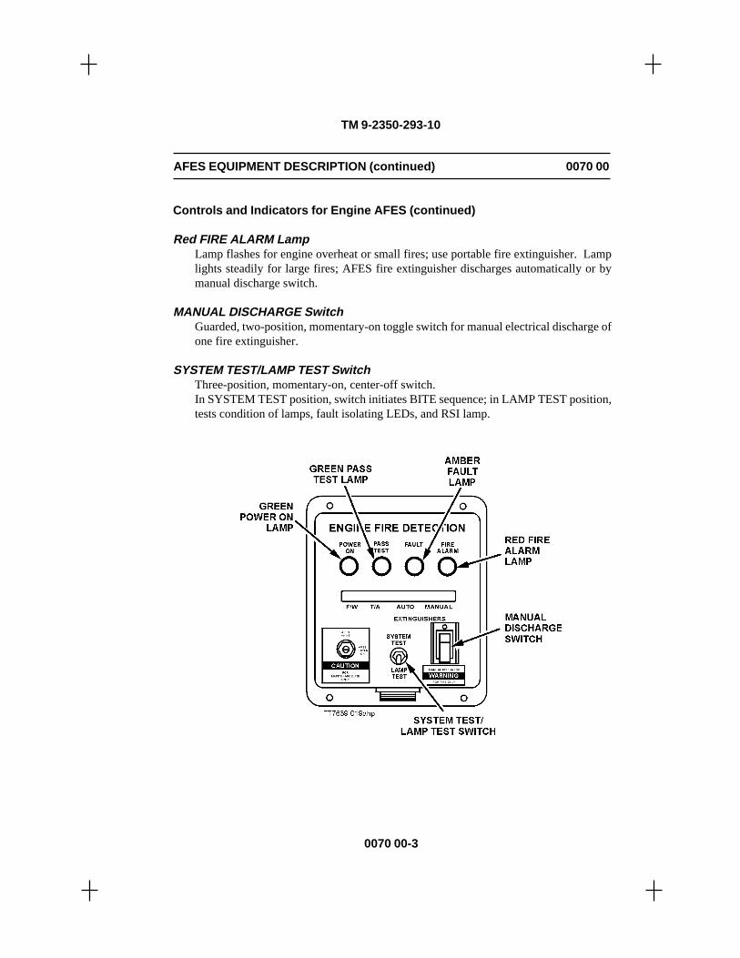
0070 00-3
TM 9-2350-293-10
Controls and Indicators for Engine AFES (continued)
Red FIRE ALARM LampLamp flashes for engine overheat or small fires; use portable fire extinguisher. Lamplights steadily for large fires; AFES fire extinguisher discharges automatically or bymanual discharge switch.
MANUAL DISCHARGE SwitchGuarded, two-position, momentary-on toggle switch for manual electrical discharge ofone fire extinguisher.
SYSTEM TEST/LAMP TEST SwitchThree-position, momentary-on, center-off switch.In SYSTEM TEST position, switch initiates BITE sequence; in LAMP TEST position,tests condition of lamps, fault isolating LEDs, and RSI lamp.
AFES EQUIPMENT DESCRIPTION (continued) 0070 00

0070 00-4
TM 9-2350-293-10
Controls and Indicators for Engine AFES (continued)
Fault Isolation LEDsIf FAULT lamp lights during BITE, fault isolating LEDs will also light to indicate whichcomponent(s) is nonoperational and requires fault correction. The four LEDs are:
AFES EQUIPMENT DESCRIPTION (continued) 0070 00
F/W ..................................... Fire WireT/A ...................Test and Alarm PanelAUTO ........... Fire extinguisher No. 1MANUAL..... Fire extinguisher No. 2
LEDs will not light if vehicle batterypower is low.
CAUTION
AFES MAINT/AFES POWER ON switch isto be used by authorized Unit and DirectSupport maintenance personnel only.
AFES MAINT/AFES POWER ON SwitchTwo-position, screwdriver-activated, rotary switch.
Vertical position (AFES MAINT): Power off, AFESdeenergized. Maintenance can be safely performed. Lockingpins must be installed in fire extinguisher No. 2 valveactuator guard to prevent accidental discharge. Check No.1 extinguisher pin.
Horizontal position (AFES POWER ON): Power on. Normaloperational position. AFES extinguishers capable ofautomatic discharge. Locking pins must be removed fromengine fire extinguisher No. 2 valve actuator guard.
Red Remote Status Indicator (RSI) LightLight flashes in crew compartmentduring an engine overheat or smallfire; light illuminates steadily during alarge engine fire. Normally, light isnot lit.

0070 00-5
TM 9-2350-293-10
AFES EQUIPMENT DESCRIPTION (continued) 0070 00
Controls and Indicators for Crew AFES
Green POWER ON LampLamp lights when AFES is powered on.POWER ON lamp remains lit for 2-4 hours after vehicle MASTER switch is turned off.
Green PASS TEST LampLamp lights for 4-6 seconds following a successful BITE test.
Amber FAULT LampLamp flickers at start of system test. Lamp lights when BITE detects a fault and stayslit until fault is corrected.
Red FIRE ALARM LampLamp flashes for engine overheat or small fires; use portable fire extinguisher. Lamplights steadily for large fires; AFES fire extinguisher discharges automatically or bymanual discharge switch.
MANUAL DISCHARGE SwitchGuarded, two-position, momentary-on toggle switch manually and electrically dischargesthree extinguishers. After 5 seconds a second set of three extinguishers can also bedischarged.
SYSTEM TEST/LAMP TEST SwitchThree-position, momentary-on, center-off switch.
In SYSTEM TEST position, switch initiates BITE sequence; in LAMP TEST position,tests condition of lamps and fault isolating LEDs.

Controls and Indicators for Crew AFES (continued)
Vehicles 1 Through 344
Fault Isolation LEDs:If the FAULT lamp lights during BITE, fault isolating LEDs will also light to indicatewhich component(s) is nonoperational and requires fault correction. The ten LEDs are:
TM 9-2350-293-10
AFES EQUIPMENT DESCRIPTION (continued) 0070 00
FIRE 1 ......... OFSA No. 1 DET 2 ......... OFSA No. 2
3 ......... OFSA No. 34 ......... OFSA No. 4
FIRE 1 ......... Extinguisher No. 1EXT 2 ......... Extinguisher No. 2
3 ......... Extinguisher No. 34 ......... Extinguisher No. 4
0070 00-6
SCEA .... Standard ControlElectronic Amplifier
T/A ........ Test and Alarm Panel
LEDs will not light if battery is low.
AFES MAINT/AFES POWER ON Switch: Vehicles 1 Through 344
CAUTION
AFES MAINT/AFES POWER ON switch is to be used byauthorized Unit and Direct Supportmaintenance personnel only.
Two position, screwdriver-activated rotary switch.
Vertical position (AFES MAINT): Power off. AFESdeenergized. Maintenance can be safely performed. Lockingpins must be installed on crew fire extinguishers No. 3 andNo. 4 valve actuator guards to prevent accidental discharge.Check other extinguisher pins.
Horizontal position (AFES POWER ON): Power on. Normaloperational position. AFES extinguishers capable of automaticdischarge. Locking pins must be removed from crew fireextinguishers No. 3 and No. 4.

TM 9-2350-293-10
AFES EQUIPMENT DESCRIPTION (continued) 0070 00
0070 00-7/8 blank
Controls and Indicators for Crew AFES (continued)
Vehicles 345 and Above
Fault Isolation LEDs:If the FAULT lamp lights during BITE, fault isolating LEDs will also light to indicatewhich component (s) is nonoperational and requires fault correction. The 11 LEDs are:
1 ....... OFSA No. 1FIRE 2 ....... OFSA No. 2DET 3 ....... OFSA No. 3
4 ....... OFSA No. 4
1 ....... Extinguisher No. 12 ....... Extinguisher No. 2
FIRE 3 ....... Extinguisher No. 3EXT 4 ....... Extinguisher No. 4
5 ....... Extinguisher No. 56 ....... Extinguisher No. 6
SCEA .... Standard ControlElectronic Amplifier
LEDs will not light if battery is low.
AFES MAINT/AFES POWER ON Switch: Vehicles 345 and Above
CAUTION
AFES MAINT/AFES POWER ON switch is to be used byauthorized Unit and Direct Support maintenancepersonnel only.
Two-position, screwdriver-activated rotary switch.
Vertical position (AFES MAINT): Power off. AFES de-energized.Maintenance can be safely performed. Locking pins must beinstalled on crew fire extinguishers No. 3 and No. 4 valve actuatorguards to prevent accidental discharge. Check other extinguisherpins.
Horizontal position (AFES POWER ON): Power on. Normaloperational position. AFES extinguishers capable of automaticdischarge. Locking pins must be removed from crew fireextinguishers No. 3 and No. 4.
END OF WORK PACKAGE


0071 00
THIS WORK PACKAGE COVERS:Engine AFES Components, Crew AFES Components, and Automatic FireExtinguishing System Manual Discharge System (AFES/MDS) Components
INITIAL SETUP:Maintenance Level
Operator
0071 00-1
TM 9-2350-293-10
OPERATOR'S MANUALCARRIER, AMMUNITION, TRACKED, M992A2
AFES COMPONENT LOCATION
ENGINE AFES COMPONENTS
1. Engine Fire Extinguisher No. 12. Lanyard Cable Pull Handle (Exterior)3. Actuator Assembly4. Engine Test and Alarm (T/A) Panel5. Fire Extinguisher Wiring Harness W46. Halon Distribution System7. Thermal Detection System

AFES COMPONENT LOCATION (continued) 0071 00
0071 00-2
TM 9-2350-293-10
ENGINE AFES COMPONENTS (continued)
The engine AFES activates automatically when the thermal detection system detects enginefires. Engine AFES components are described on pages 0071 00-2 through 0071 00-4.
Engine T/A Panel
• The T/A panel provides status lights and switches and contains the electronic circuitrynecessary to automatically monitor the engine AFES.
• The T/A panel monitors the thermal sensing element (fire wire) and activates one of theengine fire extinguishers when an engine fire is detected.
• When an engine fire is detected, the red FIRE ALARM indicator on the T/A panel andthe red ENGINE FIRE indicator on the remote status indicator (RSI) in the crewcompartment light.
• The T/A panel is also equipped with a red-guarded, two-position MANUAL DISCHARGEtoggle switch that allows the driver to discharge the two engine fire extinguishers.
• The engine AFES contains Built-In Test Equipment (BITE) that automatically monitorsthe status of AFES components.
• BITE permits the driver to check the status of AFES components for normal operation.

0071 00-3
TM 9-2350-293-10
AFES COMPONENT LOCATION (continued) 0071 00
ENGINE AFES COMPONENTS (continued)
Thermal Detection System
• The thermal detection system consists of fire-sensing elements and couplings loopedthroughout the engine compartment.
• The fire-sensing elements detect engine overheat conditions and fires.
• When the system detects an engine overheat condition, the engine T/A panel FIREALARM lamp and the RSI ENGINE FIRE lamp flash.
• When the system detects an engine fire, both indicator lamps light and the systemautomatically activates the engine automatic fire extinguisher.

0071 00-4
TM 9-2350-293-10
AFES COMPONENT LOCATION (continued) 0071 00
ENGINE AFES COMPONENTS (continued)
Remote Status Indicator (RSI)
• The RSI is a red light that warns personnel in the crew compartment of engine overheatand fires.
• The RSI ENGINE FIRE warning light and the red FIRE ALARM lamp on the engineT/A panel light at the same time.
Fire Extinguishers
• The fire extinguishers consist of steel cylinders filled with Halon and equipped with aquick-release valve assembly.
• AFES cylinders contain Halon fire suppressant pressurized with dry nitrogen for use onhydrocarbon fuel fires only.
• The engine compartment has two fire extinguishers, each weighing 10 pounds. One fireextinguisher interfaces with the thermal detection system through the enginecompartment T/A panel. It activates automatically when the thermal detection systemsenses an engine fire. The second fire extinguisher is dedicated to the AFES manualdischarge system (AFES/MDS). It is activated by pulling one of the lanyard cable pullhandles. One is located on the outside of the vehicle near the driver's hatch, and the otheris located in the driver's compartment.

0071 00-5
TM 9-2350-293-10
AFES COMPONENT LOCATION (continued) 0071 00
CREW AFES COMPONENTS
The crew AFES activates automatically when one of four OFSAs detects hydrocarbon fuelfires. Crew AFES components are described on pages 0071 00-7 through 0071 00-12.
Vehicles S/N 1 Through 344
1. Crew T/A Panel2. Standard Control Electronic Amplifier (SCEA)3. Optical Fire Sensing Assembly (OFSA)4. OFSA Cable Assembly W15. Crew Fire Extinguisher No. 26. Crew Fire Extinguisher No. 37. Crew Fire Extinguisher No. 18. Crew Fire Extinguisher Cable Assembly W39. Crew Fire Extinguisher 4*
10. SCEA Cable Assembly W2
* Activated either by crew AFES or by AFES/MDS

TM 9-2350-293-10
AFES COMPONENT LOCATION (continued) 0071 00
CREW AFES COMPONENTS (continued)
Vehicles S/N 345 and Above
1. Crew T/A Panel2. SCEA3. OFSA4. OFSA Cable Assembly W15. Crew Fire Extinguisher No. 66. Crew Fire Extinguisher No. 27. Crew Fire Extinguisher No. 58. Crew Fire Extinguisher No. 3*9. Crew Fire Extinguisher 1
10. Crew Fire Extinguisher Cable Assembly W311. Crew Fire Extinguisher No. 4*12. SCEA Cable Assembly W2
* Activated either by crew AFES or by AFES/MDS
0071 00-6

TM 9-2350-293-10
AFES COMPONENT LOCATION (continued) 0071 00
CREW AFES COMPONENTS (continued)
Crew T/A Panel
• The T/A panel provides status lamps and switches and contains the electronic circuitrynecessary to monitor the crew AFES.
• The T/A panel interfaces with the SCEA and the OFSA.
• The crew AFES has BITE, which automatically monitors the status of components andallows crew members to test the components for normal operation.
• A red-guarded, two-position MANUAL DISCHARGE toggle switch permits the crew tomanually discharge crew compartment fire extinguishers.
0071 00-7

TM 9-2350-293-10
AFES COMPONENT LOCATION (continued) 0071 00
CREW AFES COMPONENTS (continued)
CAUTION
Do not use high-pressure water when cleaning AFES components.Moisture will contaminate electrical connections, which will result infailure of the system.
OFSA
• OFSA consists of four sensor units located in the crew compartment, each using threeinfrared (IR) wave bands designed to detect hydrocarbon fuel fires.
• OFSA does not detect sunlight, electrical discharges, lamps, flashes, fragmentation, orradiation from warheads or other battlefield activity.
• OFSA units are housed in individual shock-resistant aluminum casings mounted onbrackets.
• OFSA units have BITE, which internally tests each unit for normal operation. BITEindicates a fault in the OFSA by lighting an LED on the T/A panel.
• The four OFSA units provide complete coverage of the crew compartment.
0071 00-8

TM 9-2350-293-10
AFES COMPONENT LOCATION (continued) 0071 00
0071 00-9
CREW AFES COMPONENTS (continued)
SCEA
• Processes input signals from OFSA units when hydrocarbon fuel fire is detected.
• If the fire is large, the SCEA lights the FIRE ALARM lamp on the crew compartmentT/A panel and activates the three fire extinguishers.
• If a large fire continues, or a second large fire occurs, the SCEA activates the remainingcrew compartment fire extinguishers.
• If the OFSA detects a small fuel fire, the SCEA signals the T/A panel and the FIREALARM lamp on the T/A panel flickers. The crew uses a portable fire extinguisher oractivates the MANUAL DISCHARGE switch on the T/A panel to put out the small fire.
• The SCEA contains BITE, which internally tests the unit for normal operation.
• An LED on the T/A panel lights to indicate a fault in the SCEA unit.

CREW AFES COMPONENTS (continued)
Fire Extinguishers (Vehicles S/N 1 Through 344)
• The crew AFES has four 10-pound automatic fire extinguishers.
• The fire extinguishers consist of steel cylinders filled with Halon 1301 and are equippedwith a quick-release valve assembly.
• The cylinders contain Halon fire suppressant pressurized with dry nitrogen for use onhydrocarbon fuel fires only.
• Crew AFES fire extinguishers discharge automatically when the SCEA receives anelectrical pulse from an OFSA unit, or manually when a crewmember operates theMANUAL DISCHARGE switch on the crew T/A panel.
• When the crew AFES activates, the ventilator blower automatically turns to the exhaustmode eight seconds after extinguisher discharge, and the ventilation door opensautomatically.
TM 9-2350-293-10
AFES COMPONENT LOCATION (continued) 0071 00
0071 00-10

TM 9-2350-293-10
AFES COMPONENT LOCATION (continued) 0071 00
0071 00-11
CREW AFES COMPONENTS (continued)
Fire Extinguishers (Vehicles S/N 345 and Above)
• The crew AFES has six 7-pound automatic fire extinguishers.
• The fire extinguishers consist of steel cylinders filled with Halon 1301 and are equippedwith a quick-release valve assembly.
• The cylinders contain Halon fire suppressant pressurized with dry nitrogen for use onhydrocarbon fuel fires only.
• Crew AFES fire extinguishers discharge automatically when the SCEA receives anelectrical pulse from an OFSA unit, or manually when a crewmember operates theMANUAL DISCHARGE switch on the crew T/A panel.
• When the crew AFES activates, the ventilator blower automatically turns to the exhaustmode eight seconds after extinguisher discharge, and the ventilation door opensautomatically.

TM 9-2350-293-10
AFES COMPONENT LOCATION (continued) 0071 00
0071 00-12
CREW AFES COMPONENTS (continued)
• Two crew and one engine compartment AFES fire extinguishers may be discharged fromoutside the vehicle by pulling the lanyard cable pull handle located near the driver's hatchor the pull handle located in the driver's compartment.
NOTE
Two portable fire extinguishers are also located in the crewcompartment and are separate from the AFES. One portable fireextinguisher is located on the lower rear door, and the second islocated on the left side of the crew compartment on the APU wall.These portable fire extinguishers may be used as needed on fueland electrical fires.
PORTABLE FIRE EXTINGUISHERON APU WALL
PORTABLE FIRE EXTINGUISHERON LOWER REAR DOOR

TM 9-2350-293-10
AFES COMPONENT LOCATION (continued) 0071 00
0071 00-13
AFES/MDS COMPONENTS
1. Engine Fire Ext. No. 22. Actuator Assembly3. Lanyard Cable Pull Handle (Exterior)4. Lanyard Cable Pull Handle (Driver's Compartment)

TM 9-2350-293-10
AFES COMPONENT LOCATION (continued) 0071 00
AFES/MDS COMPONENTS (continued)
WARNING
If handle retaining clip has velcro attached, remove velcro. Handlesecured with velcro could hinder ability to quickly activate AFES/MDS.Failure to follow this warning may result in severe injury or death topersonnel and destruction of equipment.
The AFES/MDS allows the crew to manually activate one engine and two crew compartmentfire extinguishers. The AFES/MDS components are described below.
ACTUATOR ASSEMBLY: The assembly controls and protects the mechanical cablingconnecting the fire extinguishers to two lanyard cable pull handles. It is equipped with anelectric sensor that opens the ventilation door when the exterior lanyard cable pull handle ispulled.
LANYARD CABLE PULL HANDLE (EXTERIOR): Located outside the vehicle near thedriver's hatch, the handle mechanically activates one engine and two crew compartment fireextinguishers. A crew member must exert a 25-pound pull to break the sealed safety wire onthe handle and must pull the handle out as far as possible to discharge the extinguishers. Thesafety wire prevents unauthorized/accidental discharge of the AFES/MDS.
LANYARD CABLE PULL HANDLE (DRIVER'S COMPARTMENT): Located on the leftwall in the driver's compartment, the handle mechanically activates one engine compartmentfire extinguisher. A crew member must pull forward on the handle to break the sealed safetywire and discharge the extinguisher. This prevents unauthorized/accidental discharge of theAFES/MDS.
0071 00-14

TM 9-2350-293-10
AFES COMPONENT LOCATION (continued) 0071 00
AFES/MDS COMPONENTS (continued)
0071 00-15/16 blank
Fire Extinguishers
• The AFES/MDS has three fire extinguishers. The one for engine fires can be activatedonly by using either lanyard cable pull handle. The other two AFES/MDS fire extinguishers,located in the crew compartment, can be activated automatically by the SCEA or byactivating the MANUAL DISCHARGE switch.
• All fire extinguishers will not activate at the same time when a crew member pulls eitherlanyard cable pull handle. Handle must be pulled to fullest extension to dischargeextinguishers.
• The fire extinguishers consist of steel cylinders filled with Halon 1301 and are equippedwith a quick-release valve assembly.
• The cylinders contain Halon fire suppressant pressurized with dry nitrogen for use onhydrocarbon fuel fires only.
END OF WORK PACKAGE


0072 00
OPERATOR'S MANUALCARRIER, AMMUNITION, TRACKED, M992A2
AFES OPERATIONAL CHECKS
THIS WORK PACKAGE COVERS:Automatic Built-In Test Equipment (BITE) Test Cycle, Engine AFES IndicatorsPower-On Operation, and Crew AFES Indicators Power-On Operation
INITIAL SETUP:Maintenance Level
Operator
0072 00-1
TM 9-2350-293-10
NOTE
Operational checkout is the same for engine and crew.
This Work Package describes, locates, and illustrates the controls and instruments of theM992A2 AFES. The location and function of all controls must be learned before operatingthe vehicle.
AUTOMATIC BUILT-IN TEST EQUIPMENT (BITE) TEST CYCLE
Key Control or Indicator Function
Turn MASTERswitch to ON.
1 POWER ON Lamp Lamp is lit.
2 PASS TEST Lamp Lights for 4-6 secondsafter successful BITE test.

Key Control or Indicator Function
3 FAULT Lamp Lamp is lit:
Perform Lamp/LED test.Replace Lamp/LED.Perform system test.
FAULT lamp or LED remains lit:
Notify Unit Maintenance.
4 FIRE ALARM Lamp Lamp flickers:
Small engine fire or engine overheat exists.Investigate and use portable fire extinguisher,if required.
Lamp is lit:
Large engine fire exists.Automatic discharge should occur. Lamp willgo out when fire is out. If lamp stays lit,evacuate vehicle and notify Unit maintenance.
AUTOMATIC BUILT-IN TEST EQUIPMENT (BITE) TEST CYCLE (continued)
TM 9-2350-293-10
AFES OPERATIONAL CHECKS (continued) 0072 00
0072 00-2

AFES OPERATIONAL CHECKS (continued) 0072 00
TM 9-2350-293-10
0072 00-3
ENGINE AFES INDICATORS POWER-ON OPERATION
NOTE
The engine AFES detects and indicates fire automatically, but thesystem may not automatically extinguish all fires. The driver shouldcontinually monitor the engine test and alarm (T/A) panel duringvehicle operation, watching for the following indications, and shouldbe prepared to take emergency action.
Key Control or Indicator Function
1 POWER ON Lamp Lamp is lit:
Lamp should remain lit throughout operation.If lamp goes out during operation, troubleshootAFES (p. 0047 00-18).
2 PASS TEST Lamp Lights 4-6 seconds after successful completion ofBITE test.
3 FAULT Lamp Lamp is not lit:
No action is required.
Lamp is lit (amber):
Notify Unit maintenance.

TM 9-2350-293-10
0072 00-4
AFES OPERATIONAL CHECKS (continued) 0072 00
ENGINE AFES INDICATORS POWER-ON OPERATION (continued)
4 FIRE ALARM Lamp Lamp is not lit:
No action required.
Lamp flickers:
Small fire or engine overheat exists. Investigateand use portable fire extinguisher, if required.
Lamp is lit (red):
Large fire exists in engine compartment.Automatic discharge should occur. Lamp willgo out when fire is extinguished. If lamp stayslit, evacuate vehicle and notify Unitmaintenance.
Key Control or Indicator Function

AFES OPERATIONAL CHECKS (continued) 0072 00
0072 00-5
TM 9-2350-293-10
ENGINE AFES INDICATORS POWER-ON OPERATION (continued)
In addition to the indicators on the engine T/A panel, a remote status indicator (RSI) (5) ismounted on the crew compartment ceiling to alert crew to an engine fire. An ENGINE FIRElight (6) also comes on whenever a large engine fire exists. During lamp test on vehiclesS/N 1 through 344, this light will not come on. During lamp test on vehicles S/N 345 andabove, this light will come on. During normal operation, this light will not come on.
Ventilation blower turns to exhaust mode and ventilation door opens automatically whenHalon discharges.

AFES OPERATIONAL CHECKS (continued) 0072 00
TM 9-2350-293-10
CREW AFES INDICATORS POWER-ON OPERATION
NOTE
The crew AFES detects and indicates fire automatically, but thesystem may not automatically extinguish all fires. The crew shouldcontinually monitor the crew T/A panel and the RSI during vehicleoperation, watching for the following indications, and must be preparedto take emergency action.
0072 00-6
Key Control or Indicator Function
1 POWER ON Lamp Lamp is lit:
Lamp should remain lit throughout operation.If lamp goes out during operation, troubleshootthe AFES (p. 0047 00-18).
2 PASS TEST Lamp Lights for 4-6 seconds after successful BITE test.

AFES OPERATIONAL CHECKS (continued) 0072 00
TM 9-2350-293-10
CREW AFES INDICATORS POWER-ON OPERATION (continued)
0072 00-7
Key Control or Indicator Function
3 FAULT Lamp Lamp is not lit:
No action is required.
Lamp is lit (amber):
Notify Unit maintenance.

AFES OPERATIONAL CHECKS (continued) 0072 00
TM 9-2350-293-10
CREW AFES INDICATORS POWER-ON OPERATION (continued)
0072 00-8
END OF WORK PACKAGE
Key Control or Indicator Function
4 FIRE ALARM Lamp Lamp is not lit:
No action is required.
Lamp flashes (red):
Small fire exists in crew compartment.Extinguish fire using portable fire extinguisher.
Lamp is lit (red):
Large fire exists in crew compartment.Automatic discharge should occur. Evacuatevehicle after discharge. Lamp will go out when

0073 00
OPERATOR'S MANUALCARRIER, AMMUNITION, TRACKED, M992A2
AFES EMERGENCY PROCEDURES
THIS WORK PACKAGE COVERS:AFES Manual Discharge–Engine Compartment Fires and AFES ManualDischarge–Crew Compartment Fires
INITIAL SETUP:Maintenance Level
Operator
0073 00-1
TM 9-2350-293-10
AFES MANUAL DISCHARGE–ENGINE COMPARTMENT FIRES
During normal AFES operation, the AFES will discharge an agent to extinguish fires.
The driver must be alert to manually discharge extinguishers if the automatic systemmalfunctions.
NOTE
For small fires, use portable fire extinguishers.
Use the following procedures if the automatic feature of the AFES malfunctions:
1. Lift MANUAL DISCHARGE switchguard (4), then press switch up andrelease. FAULT lamp (1) and AUTOLED (3) will light, signifyingextinguisher has discharged. FIREALARM lamp (2) will go out when fireis extinguished.

TM 9-2350-293-10
AFES EMERGENCY PROCEDURES (continued) 0073 00
0073 00-2
AFES MANUAL DISCHARGE–ENGINE COMPARTMENT FIRES (continued)
WARNING
Not all emergency fire extinguisher bottles will manually discharge atthe same time. A second shot will occur five seconds later. Stay awayfrom nozzles to avoid severe injury to personnel.
2. The following procedures must be followed if the fire does not go out:
• Turn vehicle MASTER switch to OFF.
• Pull FUEL SHUT OFF handle until engine stops.
• If electrical power is not available or if AFES malfunctions, driver must pull themanual discharge system (MDS) lanyard cable pull handle (5) located on the leftside of the driver's compartment, or pull the MDS lanyard cable pull handle (6)located outside the vehicle near the driver's hatch.

AFES EMERGENCY PROCEDURES (continued) 0073 00
TM 9-2350-293-10
0073 00-3
AFES MANUAL DISCHARGE–CREW COMPARTMENT FIRES
During normal AFES operation, the automatic system will discharge an agent toextinguish fires.
The crew must be alert to manually discharge extinguishers if the automatic systemmalfunctions.
NOTE
For small fires, use portable fire extinguishers.
Use the following procedures if the automatic feature of the AFES malfunctions:
1. Lift MANUAL DISCHARGE switch guard (4), then press switch up and release.FAULT lamp (1) and FIRE EXT LEDs (3) will light, signifying extinguishers havedischarged. If fire is not extinguished after 5 seconds, again press switch up and releaseto discharge second set of fire extinguishers. FIRE ALARM lamp (2) will go off whenfire is extinguished. Vent door automatically opens and ventilation fan turns on.
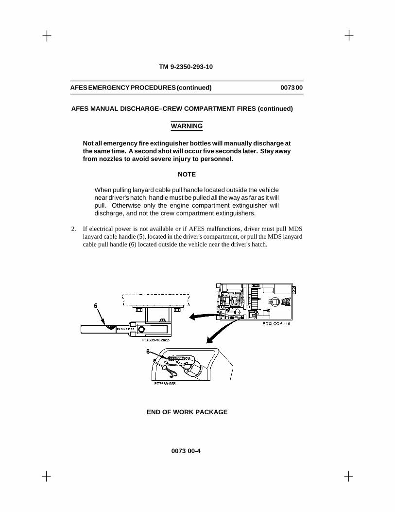
AFES MANUAL DISCHARGE–CREW COMPARTMENT FIRES (continued)
WARNING
Not all emergency fire extinguisher bottles will manually discharge atthe same time. A second shot will occur five seconds later. Stay awayfrom nozzles to avoid severe injury to personnel.
NOTE
When pulling lanyard cable pull handle located outside the vehiclenear driver's hatch, handle must be pulled all the way as far as it willpull. Otherwise only the engine compartment extinguisher willdischarge, and not the crew compartment extinguishers.
2. If electrical power is not available or if AFES malfunctions, driver must pull MDSlanyard cable handle (5), located in the driver's compartment, or pull the MDS lanyardcable pull handle (6) located outside the vehicle near the driver's hatch.
TM 9-2350-293-10
AFES EMERGENCY PROCEDURES (continued) 0073 00
0073 00-4
END OF WORK PACKAGE

CHAPTER 6
SUPPORTING INFORMATION
TM 9-2350-293-10


Scope
This Work Package lists all forms, field manuals, technical manuals, regulations, pamphlets,bulletins, miscellaneous publications, and videotapes referenced in this manual, as well asother pertinent publications.
Forms
Recommended Changes to Publications and Blank Forms..........................DA Form 2028Recommended Changes to Equipment Technical Publications ............... DA Form 2028-2Equipment Inspection and Maintenance Worksheet ....................................DA Form 2404Motor Vehicle Accident Report ........................................................................ SF Form 91Product Quality Deficiency Report ................................................................. SF Form 368
Field Manuals
NBC Protection ........................................................................................................ FM 3-4NBC Decontamination ............................................................................................. FM 3-5First Aid for Soldiers ............................................................................................ FM 21-11Driver Selection, Training and Supervision, Track Combat Vehicles ................. FM 21-17Manual for the Track Combat Vehicle Driver ................................................... FM 21-306Browning Machine Gun, Caliber .50 HB, M2 ..................................................... FM 23-65Basic Cold Weather Manual ................................................................................. FM 31-70Northern Operations ............................................................................................. FM 31-71
Technical Manuals
Operator's and Organizational Maintenance Manual: For Alarm,Chemical Agent, Automatic: Portable, Manpack, M8 (NSN 6665-00-935-6955) Fixed Emplacement, M10 (6665-00-169-1446) forTrucks, Utility: 1/4-Ton, M11 (6665-00-169-1447); for Truck:3/4-Ton, M12 (6665-00-169-1448); for Truck: 2 1/2-Ton, M13(6665-00-169-1449); for Full-Tracked, Armored PersonnelCarriers and Recovery Vehicles, M14 (6665-00-169-1450);for Carrier, Comand and Reconnaissance, Armored,M15 (6665-00-169-1451) with Power Supply for Truck,Utility: 1/4-Ton, M16 (6665-00-169-1452); withPower Supply for Truck: 3/4-Ton, M17 (6665-00-169-1453) and with Power Supply for Truck: 2-1/2 Ton,M18 (6665-00-169-1454) .............................................................. TM 3-6665-225-12
OPERATOR'S MANUALCARRIER, AMMUNITION, TRACKED, M992A2
REFERENCES
TM 9-2350-293-10 0074
0074 00-1

TM 9-2350-293-10
REFERENCES (continued) 0074 00
0074 00-2
Technical Manuals (continued)
Operator's Manual for Machine Guns, Caliber .50; Browning, M2,Heavy Barrel Flexible, W/E (NSN 1005-00-322-9715)(EIC: 4AG) ................................................................................ TM 9-1005-213-10
Operator's Manual for Rifle, 5.56 MM, M16A2 W/E (NSN 1005-01-128-9936) (EIC: 4GM; Rifle, 5.56 MM, M16A3 (1005-01-357-5112); Rifle, 5.56 MM, M16A4 (1005-01-383-2872)(EIC: 4F9); Carbine, 5.56 MM, M4 W/E (1005-01-231-0973)(EIC: 4FJ); Carbine, 5.56 MM, M4A1 (1005-01-382-0953)(EIC: 4GC) ................................................................................... TM 9-1005-319-10
Hand Receipt: Carrier, Ammunition, Tracked,M992A2 ................................................................................. TM 9-2350-293-10-HR
Operator's Manual for Howitzer, Medium, Self-Propelled:155MM, M109A6 (NSN 2350-01-305-0028) .............................. TM 9-2350-314-10
Operator's Manual: Towbar, Motor Vehicle ....................................... TM 9-4910-496-10Operator's, Unit, Direct Support and General Support
Maintenance Manual for Lead-Acid Storage Batteries ................. TM 9-6140-200-14Operator's and Unit Maintenance Manual Including Repair
Parts and Special Tools List for Heater, Water and Ration(HWR) (NSN 7310-01-387-1305) ......................................... TM 10-7310-241-12&P
Operations and Maintenance Manual for Satellite SignalsNavigation Sets AN/PSN-11 (NSN 5825-01-374-6643)and AN/PSN-11(V)1 (5825-01-395-3513) ................................. TM 11-5825-291-13
Operator's Manual for Vehicular Intercommunication Set,AN/VIC-3(V) .............................................................................. TM 11-5830-263-10
Destruction of Conventional Ammunition and ImprovedConventional Munitions (ICM) to Prevent Enemy Use .....................TM 43-0002-33
Painting Instructions for Army Materiel ......................................................... TM 43-0139Transportability Guidance: Carrier, Cargo, Full-Tracked: 7-Ton,
Amminition, M992 (NSN 2350-01-110-4660) FieldArtillery Ammunition Support Vehicle (FAASV) ................... TM 55-2350-267-14
Procedures for Destruction of Tank-Automotive Equipmentto Prevent Enemy Use ........................................................................... TM 750-244-6
Regulations, Pamphlets, Bulletins
The Army Publishing and Printing Program ...................................................... AR 25-30Prevention of Motor Vehicle Accidents ........................................................... AR 385-55Consolidated Index of Army Publications and Blank Forms .................... DA Pam 25-30Functional Users Manual for The Army Maintenance
Management System (TAMMS) ..................................................... DA Pam 738-750

END OF WORK PACKAGE
Cold Injury ....................................................................................................... TB MED 81Occupational and Environmental Health Prevention, Treatment
and Control of Heat Injury ...................................................................... TB MED 507
Miscellaneous Publications
Army Medical Department Expendable/Durable Items ..................................... CTA 8-100Expendable/Durable Items (Except: Medical, Class V, Repair
Parts and Heraldic Items) .......................................................................... CTA 50-970Fire Extinguishing Systems for the M992A2 Field Artillery
Ammunition Support Vehicle (Videotape) ...................... Tape No. 709876/TVT 5-34
REFERENCES (continued) 0074 00
0074 00-3/4 blank


TM 9-2350-293-10
0075 00-1
.
INTRODUCTION
Scope
This Work Package lists COEI and BII for the M992A2 to help you inventory the items forsafe and efficient operation of equipment.
General
The COEI and BII information is divided into the following lists:
Components of End Item (COEI). This listing is for information purposes only and is notauthority to requisition replacements. These items are part of the M992A2. As part of theend item, these items must be with the end item whenever it is issued or transferred betweenproperty accounts. Items of COEI are removed and packaged separately for transportationor shipment only when necessary. Illustrations are furnished to help you find and identifythe items.
Basic Issue Items (BII). These essential items are required in order to place the M992A2 inoperation, to operate it, and to perform emergency repairs. Although shipped separatelypackaged, BII must be with the M992A2 during operation and when it is transferred betweenproperty accounts. Listing these items is your authority to request/requisition them forreplacement based on authorization of the end item by the Table of Organization andEquipment (TOE)/Modification Table of Organization and Equipment (MTOE). Illustrationsare furnished to help you find and identify the items.
Explanation of Columns in the COEI List and BII List
Column (1) – ILLUS. NUMBER. Gives you the number of the item illustrated.
Column (2) – NATIONAL STOCK NUMBER. Identifies the stock number of the item tobe used for requisitioning purposes.
Column (3) – DESCRIPTION, CAGEC, and PART NUMBER. Identifies the Federal itemname (in capital letters) followed by a minimum description when needed. The stowagelocation of COEI and BII is also located in this column. The last line below the descriptionis the CAGEC (Commercial and Government Entity Code) (in parentheses) and the partnumber.
OPERATOR'S MANUALCARRIER, AMMUNITION, TRACKED, M992A2
COMPONENTS OF END ITEM (COEI) AND BASIC ISSUE ITEMS (BII) LISTS
0075 00

TM 9-2350-293-10
0075 00-2
COEI AND BII LISTS (continued) 0075 00
INTRODUCTION (continued)
Explanation of Columns (continued)
Column (4) – U/M [Unit of Measure]. Indicates the physical measurement or count of theitem as issued per the national stock number shown in column (2).
Column (5) – QTY. RQR. Indicates the quantity required.
COEI LIST

TM 9-2350-293-10
0075 00-3
COEI AND BII LISTS (continued) 0075 00
COEI LIST (continued)
1 5830-01-449-2251 AN/VIC-3(V) INTERCOMMUNICA- SET 1TION (at crew positions)(80063) A3210688
2 1025-01-202-0418 ARM, ADAPTER ASSEMBLY (machine EA 1gun mount)(19200) 12011777
3 3990-01-179-9141 BINDER, LOAD HOIST (in crew EA 1compartment)(79805) 1100020
4 2590-01-220-0123 LIFTING FIXTURE (in crew EA 1(compartment)(19207) 12333570
5 1005-00-704-6650 MOUNT, MACHINE GUN, CALIBER EA 10.50 (on commander's cupola)(19204) 7046650
6 1240-01-319-8995 PERISCOPE, ARMORED VEHICLE, EA 1M27 (at commander's cupola)(19200) 12357792
7 6650-01-418-6658 PERISCOPE, ARMORED VEHICLE, EA 3M45 (at driver's hatch)(19207) 12370033
(1)ILLUS.
NUMBER
(2)NATIONAL STOCK
NUMBER
(5)QTY.RQR.
(4)
U/M
(3)DESCRIPTION,
CAGEC, AND PART NUMBER
Table 1. Components of End Item List

TM 9-2350-293-10
0075 00-4
COEI AND BII LISTS (continued) 0075 00
BII LIST
Table 2. Basic Issue Items List
1 5935-00-322-8959 ADAPTER, CONNECTOR CABLE EA 2(in satchel tool bag)(19207) 11677570
2 4930-00-204-2550 ADAPTER, GREASE GUN (on greasegun) EA 1(19207) 5349744
3 2540-00-670-2459 BAG ASSEMBLY, PAMPHLET (under EA 1right-hand rear canister compartment)(19207) 11676920
4 5140-00-473-6256 BAG, TOOL, SATCHEL (under right- EA 1hand rear canister compartment)(34623) 11655979
5 2540-00-906-4741 BOX ASSEMBLY, SPARE BULB (in EA 1driver's compartment)(19207) 10870949
(1)ILLUS.
NUMBER
(2)NATIONAL STOCK
NUMBER
(5)QTY.RQR.
(4)
U/M
(3)DESCRIPTION,
CAGEC, AND PART NUMBER

TM 9-2350-293-10
0075 00-5
COEI AND BII LISTS (continued) 0075 00
Table 2. Basic Issue Items List (continued)
BII LIST (continued)
6 5120-01-179-8995 BREAKER, CHAIN (in satchel tool bag) EA 1(19207) 12330762
7 6150-01-248-9555 CABLE ASSEMBLY, POWER (under EA 1right-hand rear canister compartment)(19207) 11682336-6
8 CAN, WATER, MILITARY, 5-GALLON EA 4(three on front exterior cargo compart-ment, one on lower rear door)(81349) MIL-C-43613
7240-00-089-3827 TYPE-1 (tan)7240-01-365-5317 TYPE-2 (green)
9 3020-00-231-8732 CONNECTING LINK ASSEMBLY, EA 2COUPLING (in satchel tool bag)(73433) D40-2CL
10 5340-01-179-8994 CRANK, HAND (in satchel tool bag) EA 1(19207) 12333374
11 5120-00-224-1390 CROWBAR (on top plate of cargo EA 1compartment, exterior, left of comman-der's cupola)(80064) 1833244
(1)ILLUS.
NUMBER
(2)NATIONAL STOCK
NUMBER
(5)QTY.RQR.
(4)
U/M
(3)DESCRIPTION,
CAGEC, AND PART NUMBER

TM 9-2350-293-10
0075 00-6
COEI AND BII LISTS (continued) 0075 00
Table 2. Basic Issue Items List (continued)
BII LIST (continued)
12 5110-00-595-8229 CUTTER, WIRE ROPE (in satchel tool EA 1bag)(19207) 11655981
13 5120-00-243-7326 EXTENSION, SOCKET WRENCH, EA 11/2-INCH DRIVE, 5 INCHES (in satcheltool bag)(95683) 41B306
14 5120-00-227-8074 EXTENSION, SOCKET WRENCH, EA 11/2-INCH DRIVE, 10 INCHES (insatchel tool bag)(19207) 11655788-1
15 4210-01-388-7854 EXTINGUISHER, FIRE (CO2) (one on EA 2
interior of lower rear door, one on rearAPU compartment bulkhead)(58536) A52471-1-S
16 5110-00-156-0059 FILE, HAND (in satchel tool bag) EA 1(19204) 41F1030
17 6545-00-922-1200 FIRST AID KIT (in stowage box) EA 1(64616) SC C-6545-IL VOL 2
(1)ILLUS.
NUMBER
(2)NATIONAL STOCK
NUMBER
(5)QTY.RQR.
(4)
U/M
(3)DESCRIPTION,
CAGEC, AND PART NUMBER

TM 9-2350-293-10
0075 00-7
COEI AND BII LISTS (continued) 0075 00
(1)ILLUS.
NUMBER
(2)NATIONAL STOCK
NUMBER
(5)QTY.RQR.
(4)
U/M
(3)DESCRIPTION,
CAGEC, AND PART NUMBER
18 5120-00-605-3926 FIXTURE, TRACK (on exterior of front EA 2cargo compartment, right of driver's hatch)(19207) 8741739
19 6230-00-264-8261 FLASHLIGHT (one at driver's position, EA 2one at commander's position)(21108) MX-991/4
20 7510-01-065-0166 FOLDER, EQUIPMENT RECORD EA 1(in pamphlet bag)(81349) MIL-F-43986
21 5120-01-355-2052 HAMMER, HAND (in satchel tool bag) EA 1(55719) BPN32A
22 5340-01-199-9941 HANDLE EXTENSION, PROJECTILE EA 1LOCK (under right-hand rear canistercompartment)(19207) 12351610
23 5120-00-249-1076 HANDLE, SOCKET WRENCH, EA 13/4-INCH DRIVE (in satchel tool bag)(80064) 1940708
Table 2. Basic Issue Items List (continued)
BII LIST (continued)

TM 9-2350-293-10
0075 00-8
COEI AND BII LISTS (continued) 0075 00
(1)ILLUS.
NUMBER
(2)NATIONAL STOCK
NUMBER
(5)QTY.RQR.
(4)
U/M
(3)DESCRIPTION,
CAGEC, AND PART NUMBER
24 5120-00-236-7590 HANDLE, SOCKET WRENCH, EA 1HINGED, 1/2-INCH DRIVE (in satcheltool bag)(19207) 11655786-1
25 5120-01-179-8997 HOOK, CARTRIDGE REMOVER EA 1(in satchel tool bag)(19207) 12333373
26 5120-00-240-5300 KEY, SOCKET HEAD SCREW, EA 13/16-INCH HEX (in satchel tool bag)(94697) A05522-011
27 5120-00-240-5274 KEY, SOCKET HEAD SCREW, EA 15/16-INCH HEX (in satchel tool bag)(55719) AW1O
28 5120-00-198-5390 KEY, SOCKET HEAD SCREW, EA 13/8-INCH HEX (in satchel tool bag)(80064) 1940722
29 5120-00-224-2510 KEY, SOCKET HEAD SCREW, EA 15/8-INCH HEX (in satchel tool bag)(74445) 57036
Table 2. Basic Issue Items List (continued)
BII LIST (continued)

TM 9-2350-293-10
0075 00-9
COEI AND BII LISTS (continued) 0075 00
(1)ILLUS.
(2)NATIONAL STOCK
(5)QTY.
(4)(3)DESCRIPTION,
30 5180-01-388-7855 KIT, PULLER, CONNECTOR, TRACK EA 1(in satchel tool bag)(19207) 57K3156, which consists of:
PIN, THREADED (see item 42)
PULLER BOLT (see item 45)
31 6240-00-266-9940 LAMP, INCANDESCENT (in spare EA 3lamp box)(96906) MS25231-1829
32 5980-01-296-2793 LIGHT-EMITTING DIODE (LED) EA 2(in spare lamp box)(19207)12360890-3
33 3020-01-251-7713 LINK, ROLLER CHAIN CONVEYOR EA 5(in satchel tool bag)(76474) C2060H
34 4930-00-766-3545 LUBRICATION GUN, HAND EA 1(in satchel tool bag)(36251) 102758
Table 2. Basic Issue Items List (continued)
BII LIST (continued)

TM 9-2350-293-10
0075 00-10
(1)ILLUS.
NUMBER
(2)NATIONAL STOCK
NUMBER
(5)QTY.RQR.
(4)
U/M
(3)DESCRIPTION,
CAGEC, AND PART NUMBER
35 TM 9-2350-293-10 MANUAL, OPERATOR'S EA 1(in pamphlet bag)
36 8415-01-092-0039 MITTEN, HEAT PROTECTION EA 2(in satchel tool bag)(81349) MIL-M-11199
37 4930-00-262-8868 OILER, HAND (in satchel tool bag) EA 1(72798) 328
38 5340-01-269-9345 PADLOCK SET (in satchel tool bag) EA 1(96906) MS 21313-53
39 8345-00-174-6865 PANEL MARKER (in satchel tool bag) EA 2(64067) 8345-00-174-6865
40 6650-01-418-6658 PERISCOPE, ARMORED VEHICLE, EA 1M45 (in driver's stowage box)(19207) 12370033
COEI AND BII LISTS (continued) 0075 00
Table 2. Basic Issue Items List (continued)
BII LIST (continued)

TM 9-2350-293-10
0075 00-11
COEI AND BII LISTS (continued) 0075 00
41 5315-00-829-1480 PIN, COTTER (in satchel tool bag) EA 5(96906) MS24665-208
42 5315-01-412-5332 PIN, THREADED (on puller) EA 1(19207) 12438988
43 5340-01-158-7062 PLATE, MENDING, CONVEYOR PAD EA 5(in satchel tool bag)(19207) 12376413
44 5120-00-239-8251 PLIERS (in satchel tool bag) EA 1(72368) 1950
45 5306-01-388-5186 PULLER BOLT (on puller) EA 2(19207) 12447293
46 5320-01-193-6934 RIVET, BLIND, 0.188-INCH DIA (in EA 20satchel tool bag)(19207) 12351907-1
47 5120-01-367-3873 RIVET GUN, PIN (in satchel tool bag) EA 1(55719) HP2
(1)ILLUS.
NUMBER
(2)NATIONAL STOCK
NUMBER
(5)QTY.RQR.
(4)
U/M
(3)DESCRIPTION,
CAGEC, AND PART NUMBER
Table 2. Basic Issue Items List (continued)
BII LIST (continued)

TM 9-2350-293-10
0075 00-12
48 5120-00-596-8502 SCREWDRIVER, FLAT TIP (in satchel EA 1tool bag)(96906) MS15221-2
49 4030-01-397-7347 SHACKLE (in satchel tool bag) EA 1(19207) 12438986
50 2540-01-381-2587 SHROUD ASSEMBLY, DOOR (under EA 1right rear canister racks)(19207) 12447290
51 5120-00-237-0984 SOCKET, SOCKET WRENCH, EA 11/2-INCH, 1/2-INCH DRIVE (in satcheltool bag)(95683) 41W3007
52 5120-00-189-7932 SOCKET, SOCKET WRENCH, EA 19/16-INCH, 1/2-INCH DRIVE (in satcheltool bag)(05506) ST-1218
53 5120-00-189-7985 SOCKET, SOCKET WRENCH, EA 13/4-INCH, 1/2-INCH DRIVE (in satcheltool bag)(19207) 11677025-4
(1)ILLUS.
NUMBER
(2)NATIONAL STOCK
NUMBER
(5)QTY.RQR.
(4)
U/M
(3)DESCRIPTION,
CAGEC, AND PART NUMBER
COEI AND BII LISTS (continued) 0075 00
Table 2. Basic Issue Items List (continued)
BII LIST (continued)

TM 9-2350-293-10
0075 00-13
COEI AND BII LISTS (continued) 0075 00
Table 2. Basic Issue Items List (continued)
BII LIST (continued)
54 5120-00-189-7946 SOCKET, SOCKET WRENCH, EA 15/8-INCH, 1/2-INCH DRIVE (in satcheltool bag)(05506) ST-1220
55 5120-00-189-7934 SOCKET, SOCKET WRENCH, 17/8-INCH, 1/2-INCH DRIVE (in satcheltool bag)(19207) 1167025-5
56 5120-00-935-7425 SOCKET, SOCKET WRENCH, EA 115/16-INCH, 1/2-INCH DRIVE (insatchel tool bag)(30106) A-30
57 5120-00-189-7927 SOCKET, SOCKET WRENCH, EA 11-INCH, 1/2-INCH DRIVE (in satcheltool bag)(19207) 11677025-7
58 5120-00-239-0021 SOCKET, SOCKET WRENCH, EA 11-1/8 INCH, 3/4-INCH DRIVE (insatchel tool bag)(34871) FAC01027
59 5120-00-235-5871 SOCKET, SOCKET WRENCH, EA 11-1/4 INCH, 3/4-INCH DRIVE (insatchel tool bag)(28265) 3105A
60 5120-00-293-0094 SOCKET, SOCKET WRENCH, EA 11-1/2 INCH, 3/4-INCH DRIVE (insatchel tool bag)(26848) 47148
(1)ILLUS.
NUMBER
(2)NATIONAL STOCK
NUMBER
(5)QTY.RQR.
(4)
U/M
(3)DESCRIPTION,
CAGEC, AND PART NUMBER

TM 9-2350-293-10
0075 00-14
61 2540-00-653-7589 TARPAULIN (under right-hand rear EA 1canister compartment)(19207) 6537589
62 2530-01-346-9233 TRACK SHOE ASSEMBLY, T-154 EA 4(exterior left-hand top front hull andbattery access doors)(19207) 12268550-1
63 5110-00-221-1499 NIPPERS, END CUTTING (in satchel EA 1tool bag)(80204) B107.11M
64 4010-01-041-9752 WIRE ROPE ASSEMBLY, SINGLE EA 1LEG, 15-FOOT (on exterior surface offront cargo compartment plate)(19207) 7360553-1
65 5120-00-240-5328 WRENCH, ADJUSTABLE, 8-INCH EA 1(in satchel tool bag)(92878) 11655778-3
66 5120-00-264-3796 WRENCH, ADJUSTABLE, 12-INCH EA 1(in satchel tool bag)(19207) 11655778-5
COEI AND BII LISTS (continued) 0075 00
(1)ILLUS.
NUMBER
(2)NATIONAL STOCK
NUMBER
(5)QTY.RQR.
(4)
U/M
(3)DESCRIPTION,
CAGEC, AND PART NUMBER
END OF WORK PACKAGE
Table 2. Basic Issue Items List (continued)
BII LIST (continued)

.
INTRODUCTION
Scope
This Work Package lists additional items you are authorized for the support of the M992A2.
General
This list identifies items that do not have to accompany the M992A2 and do not have to beturned in with it. These items are all authorized to you by CTA 50-970.
Explanation of Columns in the AAL
Column (1) – NATIONAL STOCK NUMBER. Identifies the stock number of the item tobe used for requisitioning purposes.
Column (2) – DESCRIPTION, CAGEC [Commercial and Government Entity Code], ANDPART NUMBER. Identifies the Federal item name (in all capital letters) followed by aminimum description when needed. The last line below the description is the CAGEC (inparentheses) and the part number.
Column (3) – U/M [Unit of Measure]. Indicates the physical measurement or count of theitem as issued, per the national stock number shown in column (1).
Column (4) – QTY. RECM. Indicates the quantity recommended.
OPERATOR'S MANUALCARRIER, AMMUNITION, TRACKED, M992A2
ADDITIONAL AUTHORIZATION LIST (AAL)
0076 00
0076 00-1
TM 9-2350-293-10

ADDITIONAL AUTHORIZATION LIST (continued) 0076 00
(1) (2) (3) (4)NATIONAL STOCK DESCRIPTION, QTY.
NUMBER CAGEC, AND PART NUMBER U/M RECM.
4930-00-288-1511 ADAPTER, GREASE GUN EA 1 (36251) 120349
5895-01-119-9900 AMPLIFIER, POWER SUPPLY GROUP EA 1OG-174 VRC (37695) 706672-801
5110-00-293-2336 AX, SINGLE BIT EA 16150925
5120-00-526-6044 BAR, PINCH EA 1 (19204) 5266044
6135-00-450-3528 BATTERY, NONRECHARGEABLE, DRY EA 1(81349) BA3517U
6135-00-930-0030 BATTERY, NONRECHARGEABLE, DRY EA 4(80058) BA3030U
2540-00-906-4741 BOX, ACCESSORIES STOWAGE EA 1(19207) 10870949
5140-00-261-4994 CARRIER, TOOL EA 1(19207) 11655787
1290-00-824-7245 CASE, FUSE SETTER EA 1(19200) 8247245
6665-01-105-5623 CHEMICAL AGENT ALARM, M8A1(81361) C5-15-8800 EA 1
5110-00-236-3272 CHISEL, COLD, HAND EA 1(80244) GGG-C-313 TY4 CL1
4230-01-133-4124 DECONTAMINATION APPARATUS, M13 EA 1(81361) E5-51-527
0076 00-2
TM 9-2350-293-10

ADDITIONAL AUTHORIZATION LIST (continued) 0076 00
6665-01-133-4964 DETECTOR KIT, M256 EA 1
5120-00-227-8079 EXTENSION, SOCKET WRENCH, EA 116-INCH, 3/4-INCH DRIVE(55719) L122
5120-00-273-9208 EXTENSION, SOCKET WRENCH, EA 13-INCH, 3/4-INCH DRIVE(55719) L32
5110-00-241-9160 FILE, HAND EA 1(19204) 41F1572
5120-00-900-6097 HAMMER, HAND EA 1(80244) GGG-H-86 TY10 CL1
5120-00-288-6574 HANDLE, MATTOCK PICK EA 2(19207) 11677021
5120-00-241-3142 HANDLE, SOCKET WRENCH, T-SLIDING EA 1 (55719) 510
5120-00-249-1071 HANDLE, SOCKET WRENCH, EA 1NUT SPEEDER(58536) A-A-2166
5120-00-230-6385 HANDLE, SOCKET WRENCH, RATCHET EA 1 (80064) 14U1502
5120-00-099-8544 HANDLE, SOCKET WRENCH, T-SLIDING EA 1(34871) FAC01022
5110-00-222-0457 HATCHET, CLAW EA 1(80244) GGG-H-131 TYB
0076 00-3
TM 9-2350-293-10
(1) (2) (3) (4)NATIONAL STOCK DESCRIPTION, QTY.
NUMBER CAGEC, AND PART NUMBER U/M RECM.

ADDITIONAL AUTHORIZATION LIST (continued) 0076 00
5120-00-224-4659 KEY, SOCKET HEAD SCREW, EA 11/4-INCH, HEX(80064) 1940720
5120-00-240-5292 KEY, SOCKET HEAD SCREW, EA 11/8-INCH, HEX(55719) AW4
5120-00-198-5392 KEY, SOCKET HEAD SCREW, EA 15/32-INCH, HEX(16786) P848000210
5120-00-242-7410 KEY, SOCKET HEAD SCREW, EA 13/32-INCH, HEX(92674) BA27077-4
5120-01-108-1729 MAINTENANCE KIT, CBR EQUIPMENT, EA 1 M273(81361) D5-15-8194
5120-00-243-2395 MATTOCK, PICK W/O HANDLE EA 1(19207)11677022
7310-01-387-1305 MOUNTED WATER RATION HEATER EA 1(MWRH)(98308) MIL-H-44466
5120-00-194-9458 PICK, DIGGING, RAILROAD W/O HANDLE EA 1(58536) A-A-338
5315-00-861-1473 PIN, LOCK EA 1(19206) 8767184
5120-00-223-7397 PLIERS, SLIP JOINT, COMB. SLIP JOINT, EA 1W/CUTTER(8Z799) PL-8
0076 00-4
TM 9-2350-293-10
(1) (2) (3) (4)NATIONAL STOCK DESCRIPTION, QTY.
NUMBER CAGEC, AND PART NUMBER U/M RECM.

ADDITIONAL AUTHORIZATION LIST (continued) 0076 00
5825-01-374-6643 PRECISION LIGHTWEIGHT GLOBAL EA 1POSITIONING SYSTEM (GPS) RECEIVER(PLGR)(80058) AN/PSN-11
5120-00-293-0791 PUNCH, DRIVE PIN EA 1(80244) TY8 CLA 5T1SZ5
5820-01-879-9260 RADIO SET EA 1(35643) AN/PRC 68
4933-00-796-4537 ROLL ASSEMBLY, TOOL EA 1(19207) 7964537)
5120-00-234-5223 RULE, STEEL MACHINIST'S EA 1(57163) C604R-6
5120-00-236-2127 SCREWDRIVER, FLAT TIP, 3-INCH EA 1(89905) 133690-10
5120-00-278-1283 SCREWDRIVER, FLAT TIP, 6-INCH EA 1(19207) 41S1104
5120-00-227-7338 SCREWDRIVER, FLAT TIP, 5-INCH EA 1(77948) D339
5120-00-188-8450 SHOVEL, HAND, GENERAL PURPOSE, EA 1LG HANDLE(80244) TY4 CLB ST1SZ2
5120-00-293-3336 SHOVEL, HAND EA 1(19207) 11655784
5120-00-189-7931 SOCKET, SOCKET WRENCH, 1-7/16 INCH, EA 13/4-INCH DRIVE(58536) A-A-1394
0076 00-5
TM 9-2350-293-10
(1) (2) (3) (4)NATIONAL STOCK DESCRIPTION, QTY.
NUMBER CAGEC, AND PART NUMBER U/M RECM.

ADDITIONAL AUTHORIZATION LIST (continued) 0076 00
5120-00-189-7930 SOCKET, SOCKET WRENCH, 1-3/8 INCH, EA 13/4-INCH DRIVE(19204) TKEX 3BU
5120-00-232-5681 SOCKET, SOCKET WRENCH, 1-5/16 INCH, EA 13/4-INCH DRIVE(34871) FAC0140
5120-00-189-7913 SOCKET, SOCKET WRENCH, 1-1/16 INCH, EA 11/2-INCH DRIVE(05506) ST-1234
5130-00-221-8007 SOCKET, SOCKET WRENCH, 9/16-INCH, EA 11/2-INCH DRIVE(47805) IP180
5120-00-189-7924 SOCKET, SOCKET WRENCH, 7/16-INCH, EA 11/2-INCH DRIVE, MANUAL(05506) ST-1214
5130-00-221-8005 SOCKET, SOCKET WRENCH, 7/16-INCH, EA 11/2-INCH DRIVE, POWER(05506) IM140
5120-00-189-7911 SOCKET, SOCKET WRENCH, 3/8-INCH, EA 11/2-INCH DRIVE(8Z799) ST-812
5120-00-189-7914 SOCKET, SOCKET WRENCH, 1-1/8 INCH, EA 11/2-INCH DRIVE(05506) ST-1230
7310-01-310-5155 STOVE, MULTIFUEL BURNER EA 1(81349) MIL-S-44344
0076 00-6
TM 9-2350-293-10
(1) (2) (3) (4)NATIONAL STOCK DESCRIPTION, QTY.
NUMBER CAGEC, AND PART NUMBER U/M RECM.

ADDITIONAL AUTHORIZATION LIST (continued) 0076 00
5120-00-269-7971 UNIVERSAL JOINT SOCKET, 1/2-INCH EA 1DRIVE(53711) 5166189
4010-00-202-2425 WIRE ROPE ASSEMBLY (10-FOOT) EA 1(19207) 7360553
5120-00-277-7025 WRENCH, OPEN END, 15/16 X 1 INCH EA 1(19207) 11655789-5
5120-00-187-7130 WRENCH, OPEN END, 13/16 X 7/8 INCH EA 1(03914) 26-133
5120-00-224-3102 WRENCH, OPEN END, 5/8 X 3/4 INCH EA 1(58536) A-A-1356
5120-00-293-2134 WRENCH, OPEN END, 9/16 X 11/16 INCH EA 1(19207) 5323330
5120-00-187-7123 WRENCH, OPEN END, 7/16 X 1/2 INCH EA 1(14674) E1416
5120-00-277-2307 WRENCH, OPEN END, 5/16 X 3/8 INCH EA 1(95683) 41W1176-10
5120-00-264-3777 WRENCH, SPANNER, ADJUSTABLE EA 1FACE PIN(8Z799) 484
5120-00-277-9076 WRENCH, SPANNER, ADJUSTABLE EA 1HOOK(19207) 5218469
END OF WORK PACKAGE
0076 00-7/8 blank
TM 9-2350-293-10
(1) (2) (3) (4)NATIONAL STOCK DESCRIPTION, QTY.
NUMBER CAGEC, AND PART NUMBER U/M RECM.


.
INTRODUCTION
Scope
This Work Package lists expendable and durable items that you will need to operate andmaintain the M992A2. This listing is for information only and is not authority to requisitionthe listed items. These items are authorized to you by CTA 50-970, Expendable/DurableItems (Except: Medical, Class V, Repair Parts and Heraldic Items), or CTA 8-100, ArmyMedical Department Expendable/Durable Items.
Explanation of Columns
Column (1) – ITEM NUMBER. This number is assigned to the entry in the list and isreferenced in the narrative instructions to identify the item (e.g., "Use cleaning compound,Item 7, WP 0077 00)."
Column (2) – LEVEL. This column identifies the lowest level of maintenance that requiresthe listed item: C = Operator/Crew.
Column (3) – NATIONAL STOCK NUMBER. This is the national stock number assignedto the item, which you can use to requisition it.
Column (4) – ITEM NAME, DESCRIPTION, CAGEC [Commercial and Government En-tity Code], AND PART NUMBER. This column provides the other information you needto identify the item.
Column (5) – U/M [Unit of Measure]. This code shows the physical measurement or countof an item: BE (bale), CN (can), DR (drum), EA (each), GL (gallon), HD (hundred), KT (kit),LB (pound), OZ (ounce), PG (package), PT (pint), QT (quart), RL (roll), and TU (tube).
OPERATOR'S MANUALCARRIER, AMMUNITION, TRACKED, M992A2
EXPENDABLE AND DURABLE ITEMS LIST
0077 00
0077 00-1
TM 9-2350-293-10

EXPENDABLE AND DURABLE ITEMS LIST 0077 00
0077 00-2
(1) (2) (3) (4) (5)ITEM NATIONAL ITEM NAME, DESCRIPTION,
NUMBER LEVEL STOCK NUMBER CAGEC, AND PART NUMBER U/M
1 C 8040-00-262-9025 ADHESIVE 8-0Z TUBE OZ(81349) MMM-A-1617
2 C 6850-01-441-3218 ANTIFREEZE, 1-GAL. CAN GL(58536) A-A-52624
3 C 6850-01-441-3221 ANTIFREEZE, 5-GAL. CAN GL(58536) A-A-52624
4 C 6850-01-441-3248 ANTIFREEZE, 55-GAL. DRUM DR (58536) A-A-52624
5 C 9150-01-054-6453 CLEANER, LUBRICANT AND PTPRESERVATIVE,1-PT SPRAY BOTTLE,(81349) MIL-PRF-63460
6 C 6850-00-598-7328 CLEANING COMPOUND, KTENGINE COOLING SYSTEM(81349) MIL-C-10597
7 C 6850-00-227-1887 CLEANING COMPOUND, QTOPTICAL LENS, 1-QT BOTTLE(58536) A-A-59199
8 C 6850-00-224-6665 CLEANING COMPOUND, CNSOLVENT, 5-GAL. CAN(81349) MIL-PRF-11090
9 C 6850-00-224-6657 CLEANING COMPOUND, CNRIFLE BORE, 8-OZ CAN(81349) MIL-PRF-372
10 C 6850-00-224-6663 CLEANING COMPOUND, GLRIFLE BORE, 1-GAL. CAN(81349) MIL-PRF-372
TM 9-2350-293-10

EXPENDABLE AND DURABLE ITEMS LIST (continued) 0077 00
(1) (2) (3) (4) (5)ITEM NATIONAL ITEM NAME, DESCRIPTION,
NUMBER LEVEL STOCK NUMBER CAGEC, AND PART NUMBER U/M
0077 00-3
11 C 5350-00-221-0872 CLOTH, ABRASIVE, 50 SHEETS PG(80204) ANSI B74.18
12 C 5610-00-141-7838 COATING COMPOUND, CNNONSLIP, 1-GAL. CAN(58536) A-A-59166
13 C 8030-00-231-2345 CORROSION PREVENTIVE CNCOMPOUND, 1-GAL. CAN(81349) MIL-C-16173 GRADE 1
14 C 8030-00-065-0957 CORROSION RESISTANT COAT- QTING, CHEMICALLY TREATED,1-QT BOTTLE(81349) MIL-C-81706
15 C 6850-01-039-3842 DEICING-DEFROSTING AND CNANTI-ICING FLUID, 5-GAL. CAN,TYPE 2(81349) MIL-A-8243
16 C 6550-01-310-1677 DISTILLED WATER, REAGENT, PG4-GAL.(07TA6) C4350-1A
17 C 6850-00-281-3061 DRYCLEANING SOLVENT, OZ4-OZ CAN(58536) A-A-59601
18 C 6850-00-664-5685 DRYCLEANING SOLVENT, QT1-QT CAN(81346) ASTM D 235 TY1
19 C 8010-00-527-2050 ENAMEL GLOSS, BLACK, GL1-GAL. CAN(58536) A-A-2962A
TM 9-2350-293-10

0077 00-4
(1) (2) (3) (4) (5)ITEM NATIONAL ITEM NAME, DESCRIPTION,
NUMBER LEVEL STOCK NUMBER CAGEC, AND PART NUMBER U/M
20 C 8010-00-527-2053 ENAMEL GLOSS, BLACK, QT1-QT CAN(58536) A-A-2962A
21 C 8010-00-664-7653 ENAMEL, GLOSS, WHITE, 1-GAL. GLCAN(81348) TT-E-489
22 C 8010-01-088-0094 ENAMEL, SEMIGLOSS, QTOLIVE DRAB, 1-QT CAN(81348) TT-E-485
23 C 8010-00-297-2105 ENAMEL, SEMIGLOSS, OLIVE GLDRAB, 1-GAL. CAN(81348) TT-E-485
24 C 9110-00-391-7813 FUEL, JELLIED ALCOHOL, CN2.625-OZ CAN(50616) 4006
25 C 9150-01-197-7693 GREASE, AUTOMOTIVE AND OZARTILLERY (GAA),14-OZ CARTRIDGE(81349) MIL-PRF-10924
26 C 9150-01-197-7690 GREASE, AUTOMOTIVE AND LBARTILLERY (GAA), 1.75-LB CAN(98308) MIL-PRF-10924
27 C 9150-01-197-7689 GREASE, AUTOMOTIVE AND LBARTILLERY (GAA), 6.5-LB CAN(98308) MIL-PRF-10924
28 C 9150-01-326-5424 GREASE, MOLYBDENUM OZDISULFIDE, 14-OZ CARTRIDGE(39428) 1062K57
EXPENDABLE AND DURABLE ITEMS LIST (continued) 0077 00
TM 9-2350-293-10

0077 00-5
(1) (2) (3) (4) (5)ITEM NATIONAL ITEM NAME, DESCRIPTION,
NUMBER LEVEL STOCK NUMBER CAGEC, AND PART NUMBER U/M
29 C 9150-00-935-9808 HYDRAULIC FLUID, GLPETROLEUM BASE, 1-GAL. CAN(98308) MIL-PRF-6083
30 C 9150-00-189-6727 LUBRICATING OIL, ENGINE QT10W, 1-QT CAN(81349) MIL-PRF-2104
31 C 9150-00-186-6668 LUBRICATING OIL, ENGINE GL10W, 5-GAL. CAN(81349) MIL-PRF-2104
32 C 9150-00-402-4478 LUBRICATING OIL, ENGINE, QT1-QT CAN(81349) MIL-L-46167
33 C 9150-00-402-2372 LUBRICATING OIL, ENGINE, CN5-GAL. CAN(81349) MIL-PRF-46167
34 C 9150-00-186-6681 LUBRICATING OIL, ENGINE QT30W, 1-QT CAN(81349) MIL-PRF-2104
35 C 9150-00-188-9858 LUBRICATING OIL, ENGINE GL30W, 5-GAL. CAN(81349) MIL-PRF-2104
36 C 9150-00-231-2361 LUBRICATING OIL, GENERAL QTPURPOSE, 1-QT CAN(81349) MIL-PRF-3150
37 C 9150-00-231-6689 LUBRICATING OIL, GENERAL QTPURPOSE, 1-QT CAN(81348) VV-L-800
EXPENDABLE AND DURABLE ITEMS LIST (continued) 0077 00
TM 9-2350-293-10

0077 00-6
(1) (2) (3) (4) (5)ITEM NATIONAL ITEM NAME, DESCRIPTION,
NUMBER LEVEL STOCK NUMBER CAGEC, AND PART NUMBER U/M
EXPENDABLE AND DURABLE ITEMS LIST (continued) 0077 00
38 C 9150-00-231-2356 LUBRICATING OIL, GENERAL CNPURPOSE, 5-GAL. CAN(81349) MIL-PRF-3150
39 C 9150-00-231-9062 LUBRICATING OIL, GENERAL GLPURPOSE, 5-GAL. CAN(81348) VV-L-800
40 C 6640-00-285-4694 PAPER, LENS HD(81348) NNN-P-40
41 C 9150-00-250-0926 PETROLATUM, TECHNICAL, CN1.75-LB CAN(81348) VV-P-236
42 C 9150-00-250-0933 PETROLATUM, TECHNICAL, CN7.5-LB CAN(81348) VV-P-236
43 C 7920-00-205-1711 RAG, WIPING, 50-LB BALE BE(81348) DDD-R-30
44 C 8030-00-159-8176 SEALING COMPOUND, TU3-OZ TUBE(81349) MIL-S-45180
45 C 8030-00-252-3391 SEALING COMPOUND, TU11-OZ TUBE(80064) 1756371
46 C 8030-00-889-3535 TAPE, ANTISEIZING, RL1/2-INCH WIDE(58536) AA58092-2-2
TM 9-2350-293-10

0077 00-7/8 blank
(1) (2) (3) (4) (5)ITEM NATIONAL ITEM NAME, DESCRIPTION,
NUMBER LEVEL STOCK NUMBER CAGEC, AND PART NUMBER U/M
EXPENDABLE AND DURABLE ITEMS LIST (continued) 0077 00
47 C 8010-00-242-2089 THINNER, PAINT PRODUCTS, CN1-GAL. CAN(58536) A-A-2904
48 C 8010-00-558-7026 THINNER, PAINT PRODUCTS, EA5-GAL. PAIL(58536) A-A-2904
TM 9-2350-293-10


NOTE
All instructions contained in this appendix are mandatory.
0078 00
OPERATOR'S MANUALCARRIER, AMMUNITION, TRACKED, M992A2
LUBRICATIONS INSTRUCTIONS
SCOPE
The "Lubrication Instructions" supporting information consists of two work packages:0078 00 and 0079 00. These work packages list all Operator/Crew lubrication instructionsto be performed on the M992A2. Intervals (on condition or hard time) and the related man-hour times are based on normal operation. The man-hour time specified is the time you needto do all services prescribed for a particular interval. Decrease the intervals if your lubricantsare contaminated or if you are operating equipment under adverse conditions, includinglonger than usual operating hours. The intervals may be extended during periods of lowactivity. If extended, adequate preservation precautions must be taken.
On-condition (OC) intervals shall be determined by the Army Oil Analysis Program(AOAP) laboratory and shall apply unless otherwise notified. Hard-time intervals will applyin the event AOAP support is unavailable.
WARNING
Drycleaning solvent P-D-680 is toxic and flammable. Wearprotective goggles and gloves; use only in a well-ventilatedarea; avoid contact with skin, eyes, and clothes; and do notbreathe vapors. Keep away from heat or flame. Never smokewhen using drycleaning solvent. Failure to follow this warningmay result in injury or death to personnel.
TM 9-2350-293-10
0078 00-1
Clean all fittings and areas around lubrication points with drycleaning solvent (Item 14,Appendix D), or equivalent, before lubricating equipment. After lubrication, wipe offexcess oil or grease to prevent accumulation of foreign matter.

LUBRICATION INSTRUCTIONS (continued) 0078 00
SCOPE (continued)
The lubrication servies to be performed on the M992A2 are as follows:
1. Transmission Oil Level Check2. Speedometer Adapter Housing3. Final Drive Universal Joints4. Final Drive Breathers5. Main Engine Crankcase Oil Level6. Onan Model DJEAM Auxiliary Power Unit (APU) Chaincase Oil Level Check7. Onan Model DJEAM Auxiliary Power Unit (APU) Crankcase Oil Level Check8. Hatz Model 2 G 40 Auxiliary Power Unit (APU) Chaincase Oil Level Check9. Hatz Model 2 G 40 Auxiliary Power Unit (APU) Crankcase Oil Level Check
10. Hydraulic Reservoir Level Check11. Conveyor Drive and Idler Sprocket Bearings12. Canister Compartment Restraint Bars13. Driver’s Seat Moving Parts14. Roadwheel Arms15. Idler Wheel Housing16. Roadwheel and Idler Wheel Hubs17. Final Drive Level Check18. Final Drive Drain and Refill19. Towing Pintle20. Track Adjuster21. Door Hold-Open Latches22. Towing Cable23. Transmission/Main Engine AOAP Sampler Valves24. Main Engine Crankcase Drain25. Oil Can Points
These lubrications services are described on the following pages in the order listedabove.
TM 9-2350-293-10
0078 00-2

LUBRICATIONS INSTRUCTIONS (continued) 0078 00
1. TRANSMISSION OIL LEVEL CHECK
INTERVAL MAN-HOURS*
D 0.3
A 0.1
25 H or 30 D 0.1
TM 9-2350-293-10
0078 00-3
* The man-hour time specified is the time you need to do all the services prescribed.

LUBRICATIONS INSTRUCTIONS (continued) 0078 00
1. TRANSMISSION OIL LEVEL CHECK (continued)
– KEY –
WARNING
While performing engine warm-up, make sure personnel standwell clear of vehicle. Vehicle may move suddenly, causingsevere injury or death to personnel.
CAUTION
Do not check oil with engine running. Do not overfill.
OE/HDO(MIL-PRF-2104)LUBRICATINGOIL, InternalCombustionEngine, TacticalService
OEA(MIL-L-46167)LUBRICATINGOIL, InternalCombustionEngine, Arctic
Lubricants Intervals+40°F to -65°F(+4°C to -54°C)
+40°F to -10°F(+4°C to -23°C)
Above 15°F(Above -9°C)
Capacities
Intervals are asfollows: H - Hour
D - Day; Daily A - Annually
Intervals are basedon normal hours ofoperation andmoderate operatingconditions.
Expected Temperatures
Transmission48 qt
(45.43 L)OE/HDO15W40
OE/HDO15W40
OEA
TM 9-2350-293-10
0078 00-4
NOTE
• Make sure vehicle is parked on level ground beforechecking transmission oil level.

LUBRICATIONS INSTRUCTIONS (continued) 0078 00
1. TRANSMISSION OIL LEVEL CHECK (continued)
• Transmission and engine contain preservative oil uponreceipt. Preservative engine oils PE1 and PE2 areidentical to engine oil OE-40, except they contain apreservative additive. PE1 and PE2 will be used in thesame manner as the regularly used engine oil OE-40.PE1 and PE2 will also be used in the transmission untilthe first scheduled 2000-mile or semiannual oil change.
TM 9-2350-293-10
0078 00-5
Check oil level before starting engine. Oil level indicator must be within “OPERATINGRANGE” stamped on dipstick and filler cap (1). Add or drain oil (see key for required type)as required. Block vehicle tracks. With brakes applied and transmission in fourth gear, runengine at 1600-1900 rpm to warm the transmission oil. When transmission oil temperaturegage reads over 180°F, run engine at 1200-1600 rpm for one to three minutes withtransmission in neutral (N). After this period of time, oil temperature should stabilizebetween 180°F and 220°F. Stop engine, wait three to five minutes, then check oil level.

INTERVAL MAN-HOURS*
S 0.1
GAA (MIL-PRF-10924)GREASE, Automo-tive and Artillery
Lubricants Intervals+40°F to -65°F(+4°C to -54°C)
+40°F to -10°F(+4°C to -23°C)
Above 15°F(Above -9°C)
Intervals are asfollows: S - Semiannually
Intervals are basedon normal hours ofoperation andmoderate operatingconditions.
Expected Temperatures
All Temperatures
TM 9-2350-293-10
0078 00-6
LUBRICATIONS INSTRUCTIONS (continued) 0078 00
2. SPEEDOMETER ADAPTER HOUSING (continued)
* The man-hour time specified is the time you need to do all the services prescribed.
–KEY–

LUBRICATIONS INSTRUCTIONS (continued) 0078 00
2. SPEEDOMETER ADAPTER HOUSING (continued)
TM 9-2350-293-10
0078 00-7
3. FINAL DRIVE UNIVERSAL JOINTS
NOTE
Dotted leader line on the illustration indicates that lubricationis required on both sides of the vehicle.

LUBRICATIONS INSTRUCTIONS (continued) 0078 00
3. FINAL DRIVE UNIVERSAL JOINTS (continued)
Lubricate two fittings (1) on each side of vehicle with GAA. Rotate universal joints to rachfittings.
TM 9-2350-293-10
0078 00-8
GAA (MIL-PRF-10924)GREASE, Automo-tive and Artillery
Lubricants Intervals+40°F to -65°F(+4°C to -54°C)
+40°F to -10°F(+4°C to -23°C)
Above 15°F(Above -9°C)
Intervals are asfollows: S - Semiannually
Intervals are basedon normal hours ofoperation andmoderate operatingconditions.
Expected Temperatures
All Temperatures
* The man-hour time specified is the time you need to do all the services prescribed.
– KEY –
INTERVAL MAN-HOURS*
S 0.3

LUBRICATIONS INSTRUCTIONS (continued) 0078 00
4. FINAL DRIVE BREATHERS
NOTE
Dotted leader line on the illustration indicates that lubricationis required on both sides of the vehicle.
INTERVAL MAN-HOURS*
S 0.4
OE/HDO(MIL-PRF-2104)LUBRICATING OIL,Internal CombustionEngine, TacticalService
Lubricants Intervals+40°F to -65°F(+4°C to -54°C)
+40°F to -10°F(+4°C to -23°C)
Above 15°F(Above -9°C)
Intervals are asfollows: S - Semiannually
Intervals are basedon normal hours ofoperation andmoderate operatingconditions.
Expected Temperatures
* The man-hour time specified is the time you need to do all the services prescribed.
–KEY–
OE/HDO15W40
OE/HDO15W40
OEA
TM 9-2350-293-10
0078 00-9

LUBRICATIONS INSTRUCTIONS (continued) 0078 00
4. FINAL DRIVE BREATHERS (continued)
WARNING
Drycleaning solvent P-D-680 is toxic and flammable. Wearprotective goggles and gloves; use only in a well-ventilatedarea; avoid contact with skin, eyes, and clothes; and do notbreathe vapors. Keep away from heat or flame. Never smokewhen using drycleaning solvent. Failure to follow this warningmay result in injury or death to personnel.
Remove both breathers (1). Clean with drycleaning solvent. Dry, dip in oil, and install (seekey for required oil type).
5. MAIN ENGINE CRANKCASE OIL LEVEL
TM 9-2350-293-10
0078 00-10

LUBRICATIONS INSTRUCTIONS (continued) 0078 00
5. MAIN ENGINE CRANKCASE OIL LEVEL (continued)
OE/HDO(MIL-PRF-2104)LUBRICATINGOIL, InternalCombustionEngine, TacticalService
OEA(MIL-L-46167)LUBRICATINGOIL, InternalCombustionEngine, Arctic
Lubricants
Intervals
+40°F to -65°F(+4°C to -54°C)
+40°F to -10°F(+4°C to -23°C)
Above 15°F(Above -9°C)
Capacities
Intervals are asfollows: H - Hour D - Day; Daily A - Annually
Intervals are basedon normal hours ofoperation andmoderate operatingconditions.
Expected Temperatures
EngineCrankcase
27 qt(25.55 L)
OE/HDO15W40
OE/HDO15W40
OEA
INTERVAL MAN-HOURS*
D 0.2
A 0.1
*The man-hour time is the time you need to do all the services prescribed.
–KEY–
WARNING
While performing engine warm-up, make sure personnel standwell clear of vehicle. Vehicle may move suddenly, causingsevere injury or death to personnel.
CAUTION
Do not check oil when engine is running. Do not overfill.
TM 9-2350-293-10
0078 00-11

LUBRICATIONS INSTRUCTIONS (continued) 0078 00
5. MAIN ENGINE CRANKCASE OIL LEVEL (continued)
NOTE
• Make sure vehicle is parked on level ground beforechecking transmission oil level.
• Transmission and engine contain preservative oil uponreceipt. Preservative engine oils PE1 and PE2 areidentical to engine oil OE-40, except they contain apreservative additive. PE1 and PE2 will be used in thesame manner as the regularly used engine oil OE-40.PE1 and PE2 will also be used in the transmission untilthe first scheduled 2000-mile or semiannual oil change.
Before starting engine, open oil level access door (1) and check to ensure that oil level is atleast to, or above, the low (L) mark on the dipstick. If not, add oil to bring level to above Lmark on dipstick (see key for required oil type). Check for hydrostatic lock. Start engine.Warm up engine to normal operating temperature. Stop engine and wait three to five minutes.Check oil level again. If oil is within OPERATING RANGE (between L and the full [F] markon the dipstick), do not add oil. If oil level is below the L mark, add oil to within upper limitsof OPERATING RANGE on dipstick (see key for required oil type). Main engine oil fillcap (2) is in engine compartment.
NOTE
After an overnight stand, oil level may be from 3/4 to 1 inchabove F mark on the dipstick. This is not abnormal.However, if oil level is more than 1 inch above the F markhave engine checked for internal coolant or fuel oil leaks.
TM 9-2350-293-10
0078 00-12

LUBRICATIONS INSTRUCTIONS (continued) 0078 00
6. ONAN MODEL DJEAM AUXILIARY POWER UNIT (APU)CHAINCASE OIL LEVEL CHECK
INTERVAL MAN-HOURS*
S 0.2
A 0.1
*The man-hour time is the time you need to do all the services prescribed.
TM 9-2350-293-10
0078 00-13

OE/HDO(MIL-PRF-2104)LUBRICATINGOIL, InternalCombustionEngine, TacticalService
Lubricants
Intervals
+40°F to -65°F(+4°C to -54°C)
+40°F to -10°F(+4°C to -23°C)
Above 15°F(Above -9°C)
Capacities
Intervals are asfollows: H - Hour
D - Day; Daily A - Annually
Intervals are basedon normal hours ofoperation andmoderate operatingconditions.
Expected Temperatures
EngineCrankcase
1 qt(0.98 L)
OE/HDO15W40
OE/HDO15W40
OEA
LUBRICATIONS INSTRUCTIONS (continued) 0078 00
WARNING
APU chaincase oil is hot after operation. Make sure chaincaseoil is cool before checking oil level.
CAUTION
Do not check oil when engine is running. Do not overfill.
6. ONAN MODEL DJEAM AUXILIARY POWER UNIT (APU)CHAINCASE OIL LEVEL CHECK (continued) (continued) (continued) (continued) (continued)
– KEY –– KEY –– KEY –– KEY –– KEY –
NOTE
Make sure vehicle is parked on level ground before checkingAPU chaincase oil level.
TM 9-2350-293-10
0078 00-14

LUBRICATIONS INSTRUCTIONS (continued) 0078 00
6. ONAN MODEL DJEAM AUXILIARY POWER UNIT (APU)CHAINCASE OIL LEVEL CHECK (continued) (continued) (continued) (continued) (continued)
Open side APU access door. Unscrew and remove oil level dipstick (1) and wipe with cleanrag. Reinsert dipstick (1) and remove it again. Observe oil level indicated on dipstick (1). Ifoil level reads below full (F) mark, remove APU chaincase oil fill cap (2) and add oil untillevel rises to F mark (see key for required oil type). Install APU chaincase oil fill cap (2).Install dipstick (1), screw it down, and hand-tighten.
TM 9-2350-293-10
0078 00-15

LUBRICATIONS INSTRUCTIONS (continued) 0078 00
7. ONAN MODEL DJEAM AUXILIARY POWER UNIT (APU)CRANKCASE OIL LEVEL CHECK
INTERVAL MAN-HOURS*
D 0.1
A 0.1
*The man-hour time is the time you need to do all the services prescribed.
TM 9-2350-293-10
0078 00-16

LUBRICATIONS INSTRUCTIONS (continued) 0078 00
7. ONAN MODEL DJEAM AUXILIARY POWER UNIT (APU)CRANKCASE OIL LEVEL CHECK (continued) (continued) (continued) (continued) (continued)
–KEY––KEY––KEY––KEY––KEY–
OE/HDO(MIL-PRF-2104)LUBRICATINGOIL, InternalCombustionEngine, TacticalService
OEA(MIL-L-46167)LUBRICATINGOIL, InternalCombustionEngine, Arctic
Lubricants
Intervals
+40°F to -65°F(+4°C to -54°C)
+40°F to -10°F(+4°C to -23°C)
Above 15°F(Above -9°C)
Capacities
Intervals are asfollows: H - Hour
D - Day; Daily A - Annually
Intervals are basedon normal hours ofoperation andmoderate operatingconditions.
Expected Temperatures
APUCrankcase
3-1/2 qt(3.31L)
OE/HDO15W40
OE/HDO15W40
OEA
CAUTION
Do not check oil when engine is running. Do not overfill.
NOTE
Make sure vehicle is parked on level ground before checkingAPU chaincase oil level.
Open front APU access door. Unscrew andremove oil level dipstick (2) and wipe withclean rag. Reinsert dipstick (2) and removeit again. Observe oil level indicated ondipstick (2). If oil level reads below full (F)mark, remove APU crankcase oil fill cap(1) and add oil until level rises to F mark(see key for required oil type). Install APUcrankcase oil fill cap (1). Install dipstick(2), screw it down, and hand-tighten.
TM 9-2350-293-10
0078 00-17

LUBRICATIONS INSTRUCTIONS (continued) 0078 00
8. HATZ MODEL 2 G 40 AUXILIARY POWER UNIT (APU)CHAINCASE OIL LEVEL CHECK
INTERVAL MAN-HOURS*
S 0.2
A 0.1
*The man-hour time is the time you need to do all the services prescribed.
TM 9-2350-293-10
0078 00-18

LUBRICATIONS INSTRUCTIONS (continued) 0078 00
8. HATZ MODEL 2 G 40 AUXILIARY POWER UNIT (APU)CHAINCASE OIL LEVEL CHECK (continued) (continued) (continued) (continued) (continued)
–KEY––KEY––KEY––KEY––KEY–
OE/HDO(MIL-PRF-2104)LUBRICATINGOIL, InternalCombustionEngine, TacticalService
Lubricants
Intervals
+40°F to -65°F(+4°C to -54°C)
+40°F to -10°F(+4°C to -23°C)
Above 15° F(Above -9°C)
Capacities
Intervals are asfollows: S - Semiannually A - Annually
Intervals are basedon normal hours ofoperation andmoderate operatingconditions.
Expected Temperatures
APUChaincase
1 qt(0.98L)
OE/HDO15W40
OE/HDO15W40
OEA
WARNING
APU chaincase oil is hot after operation. Make sure chaincaseoil is cool before checking oil level.
CAUTION
Do not check oil when engine is running. Do not overfill.
NOTE
Make sure vehicle is parked on level ground before checkingAPU chaincase oil level.
TM 9-2350-293-10
0078 00-19

LUBRICATIONS INSTRUCTIONS (continued) 0078 00
8. HATZ MODEL 2 G 40 AUXILIARY POWER UNIT (APU)CHAINCASE OIL LEVEL CHECK (continued) (continued) (continued) (continued) (continued)
Open side APU access door. Unscrew and removeoil level dipstick (1) and wipe with clean rag. Reinsertdipstick (1) and remove it again. Observe oil levelindicated on dipstick (1). If oil level reads below full(F) mark, remove APU chaincase oil fill cap (2) andadd oil until level rises to F mark (see key forrequired oil type). Install APU chaincase oil fill cap(2). Install dipstick (1), screw it down, and hand-tighten.
9. HATZ MODEL 2 G 40 AUXILIARY POWER UNIT (APU)CRANKCASE OIL LEVEL CHECK
TM 9-2350-293-10
0078 00-20

LUBRICATIONS INSTRUCTIONS (continued) 0078 00
9. HATZ MODEL 2 G 40 AUXILIARY POWER UNIT (APU)CRANKCASE OIL LEVEL CHECK (continued) (continued) (continued) (continued) (continued)
INTERVAL MAN-HOURS*
D 0.1
A 0.1
*The man-hour time is the time you need to do all the services prescribed.
–KEY–
OE/HDO(MIL-PRF-2104)LUBRICATINGOIL, InternalCombustionEngine, TacticalService
OEA(MIL-L-46167)LUBRICATINGOIL, InternalCombustionEngine, Arctic
Lubricants
Intervals
+40°F to -65°F(+4°C to -54°C)
+40°F to -10°F(+4°C to -23°C)
Above 15°F(Above -9°C)
Capacities
Intervals are asfollows: D - Day; Daily A - Annually
Intervals are basedon normal hours ofoperation andmoderate operatingconditions.
Expected Temperatures
APUCrankcase
3-1/2 qt(25.55 L)
OE/HDO15W40
OE/HDO15W40
OEA
CAUTION
Do not check oil when engine is running. Do not overfill.
NOTE
Make sure vehicle is parked on level ground before checkingAPU chaincase oil level.
TM 9-2350-293-10
0078 00-21

LUBRICATIONS INSTRUCTIONS (continued) 0078 00
9. HATZ MODEL 2 G 40 AUXILIARY POWER UNIT (APU) CRANKCASE OIL LEVEL CHECK (continued) (continued) (continued) (continued) (continued)
Open side APU access door. Remove oil leveldipstick (1) and wipe with clean rag. Reinsertdipstick (1) and remove it again. Observe oillevel indicated on dipstick (1). If oil levelreads below full (F) mark, remove APUcrankcase oil fill cap (2) and add oil until levelrises to F mark (see key for required oil type).Install APU crankcase oil fill cap (2) anddipstick (1).
10. HYDRAULIC RESERVOIR LEVEL CHECK
INTERVAL MAN-HOURS*
D 0.1
A 0.1
*The man-hour time is the time you need to do all the services prescribed.
TM 9-2350-293-10
0078 00-22

LUBRICATIONS INSTRUCTIONS (continued) 0078 00
10. HYDRAULIC RESERVOIR LEVEL CHECK (continued)
CAUTION
Take necessary precautions to prevent entry of contaminantsinto hydraulic system.
NOTE
• Make sure vehicle is parked on level ground beforechecking hydraulic reservoir level.
• An assistant is needed for this procedure.
TM 9-2350-293-10
0078 00-23
–KEY–
OHT (MIL-PRF-6083)HYDRAULICFLUID, Petro-leum Base,Preservative,HydraulicEquipment
Lubricants
Intervals
+40°F to -65°F(+4°C to -54°C)
+40°F to -10°F(+4°C to -23°C)
Above 15°F(Above -9°C)
Capacities
Intervals are asfollows: D - Day; Daily A - Annually
Intervals are basedon normal hours ofoperation andmoderate operatingconditions.
Expected Temperatures
HydraulicReservoir
18-1/2 gal.(69.8 L)
All Temperatures

LUBRICATIONS INSTRUCTIONS (continued) 0078 00
10. HYDRAULIC RESERVOIR LEVEL CHECK (continued)
Turn MASTER switch to ON and check fluid level gage (1), located on hydraulic controlpanel. Gage pointer should read within green range. If fluid level is low, open top middledoor (3) and remove hydraulic reservoir fill cap (2). While assistant monitors fluid level ongage, add OHT until fluid level rises to full (F) mark on gage.
TM 9-2350-293-10
0078 00-24

LUBRICATIONS INSTRUCTIONS (continued) 0078 00
11. CONVEYOR DRIVE AND IDLER SPROCKET BEARINGS
NOTE
Dotted leader lines on the illustration indicate that lubricationis required on both sides of the vehicle.
INTERVAL MAN-HOURS*
S 0.1
*The man-hour time is the time you need to do all the services prescribed.
TM 9-2350-293-10
0078 00-25

LUBRICATIONS INSTRUCTIONS (continued) 0078 00
11. CONVEYOR DRIVE AND IDLER SPROCKET BEARINGS (continued)
–KEY–
GAA (MIL-PRF-10924)GREASE, Automo-tive and Artillery
Lubricants Intervals+40°F to -65°F(+4°C to -54°C)
+40°F to -10°F(+4°C to -23°C)
Above 15°F(Above -9°C)
Intervals are asfollows: S - Semiannually
Intervals are basedon normal hours ofoperation andmoderate operatingconditions.
Expected Temperatures
All Temperatures
Use a grease gun to inject GAA into the two idler sprocket grease fittings (1) and into the twodriver sprocket grease fittings (2) until grease begins to seep from bearing block (3).
TM 9-2350-293-10
0078 00-26

LUBRICATIONS INSTRUCTIONS (continued) 0078 00
12. CANISTER COMPARTMENT RESTRAINT BARS
INTERVAL MAN-HOURS*
S 0.1
*The man-hour time is the time you need to do all the services prescribed.
–KEY–
GAA (MIL-PRF-10924)GREASE, Automotiveand Artillery
Lubricants Intervals+40°F to -65°F(+4°C to -54°C)
+40°F to -10°F(+4°C to -23°C)
Above 15°F(Above -9°C)
Intervals are asfollows: S - Semiannually
Intervals are basedon normal hours ofoperation andmoderate operatingconditions.
Expected Temperatures
All Temperatures
TM 9-2350-293-10
0078 00-27

LUBRICATIONS INSTRUCTIONS (continued) 0078 00
12. CANISTER COMPARTMENT RESTRAINT BARS (continued)
Unhook restraint bar straps from eyes (2). Remove restraint bars (1) and apply light coat ofGAA to sliding portions of bars (3). Install restraint bars (1). Hook restraint bar straps toeyes (2).
13. DRIVER'S SEAT MOVING PARTS
TM 9-2350-293-10
0078 00-28

LUBRICATIONS INSTRUCTIONS (continued) 0078 00
13. DRIVER'S SEAT MOVING PARTS (continued)
INTERVAL MAN-HOURS*
S 0.1
*The man-hour time is the time you need to do all the services prescribed.
–KEY–
GAA (MIL-PRF-10924)GREASE, Automo-tive and Artillery
Lubricants Intervals+40°F to -65°F(+4°C to -54°C)
+40°F to -10°F(+4°C to -23°C)
Above 15°F(Above -9°C)
Intervals are asfollows: S - Semiannually
Intervals are basedon normal hours ofoperation andmoderate operatingconditions.
Expected Temperatures
All Temperatures
Brush GAA on vertical shaft (1),horizontal shaft (3), pivot points ofseat-adjusting lever (2), and backrestpost (4).
TM 9-2350-293-10
0078 00-29/30 blank


TM 9-2350-293-10
0079 00-1
LUBRICATIONS INSTRUCTIONS (continued) 0079 00
14. ROADWHEEL ARMS
NOTE
• All instructions contained in this appendix are mandatory.
• The "Lubrication Instructions" supporting informationconsists of two work packages: 0078 00 and 0079 00.
• Dotted leader lines on the illustration indicate that lubricationis required on both sides of the vehicle.
*The man-hour time is the time you need to do all the services prescribed.
–KEY–
GAA (MIL-PRF-10924)GREASE, Automo-tive and Artillery
Lubricants Intervals+40°F to -65°F(+4°C to -54°C)
+40°F to -10°F(+4°C to -23°C)
Above 15°F(Above -9°C)
Intervals are asfollows:S - Semiannually
Intervals are basedon normal hours ofoperation andmoderate operat-ing conditions.
Expected Temperatures
All Temperatures
INTERVAL MAN-HOURS*
S 0.8

TM 9-2350-293-10
0079 00-2
LUBRICATIONS INSTRUCTIONS (continued) 0079 00
14. ROADWHEEL ARMS (continued)
Use a grease gun to inject GAA into the 14 roadwheel arm and pivot bearing housing greasefittings (2) until grease begins to seep from relief valve (1).
15. IDLER WHEEL HOUSING
NOTE
Dotted leader lines on the illustration indicate that lubricationis required on both sides of the vehicle.

TM 9-2350-293-10
0079 00-3
LUBRICATIONS INSTRUCTIONS (continued) 0079 00
15. IDLER WHEEL HOUSING (continued)
INTERVAL MAN-HOURS*
A 0.9
Use a grease gun to inject GAA into the two idler wheel housing grease fittings (1) untilgrease begins to seep from around fittings (1).
*The man-hour time is the time you need to do all the services prescribed.
–KEY–
GAA (MIL-PRF-10924)GREASE, Automo-tive and Artillery
Lubricants Intervals+40°F to -65°F(+4°C to -54°C)
+40°F to -10°F(+4°C to -23°C)
Above 15°F(Above -9°C)
Intervals are asfollows: A - Annually
Intervals are basedon normal hours ofoperation andmoderate operat-ing conditions.
Expected Temperatures
All Temperatures

TM 9-2350-293-10
0079 00-4
LUBRICATIONS INSTRUCTIONS (continued) 0079 00
16. ROADWHEEL AND IDLER WHEEL HUBS
*The man-hour time is the time you need to do all the services prescribed.
–KEY–
INTERVAL MAN-HOURS*
D 1.0
A 1.9
GAA (MIL-PRF-10924)GREASE, Automotiveand Artillery
Lubricants Intervals+40°F to -65°F(+4°C to -54°C)
+40°F to -10°F(+4°C to -23°C)
Above 15° F(Above -9°C)
Intervals are asfollows:D - DailyA - Annually
Intervals are basedon normal hours ofoperation andmoderate operat-ing conditions.
Expected Temperatures
All Temperatures
Roadwheel and Idler WheelHubs (Check level. Usegrease gun.) (See key andthe instructions thatfollow.)
Roadwheel and IdlerWheel Hubs (Usegrease gun.) (Seekey and the instruc-tions that follow.)
NOTE
Dotted leader lines on the illustration indicate that lubricationis required on both sides of the vehicle.

TM 9-2350-293-10
0079 00-5
LUBRICATIONS INSTRUCTIONS (continued) 0079 00
16. ROADWHEEL AND IDLER WHEEL HUBS (continued)
Check roadwheel and idler wheel hubs (1) dailyafter operation for overheating or Class III leaks.Make sure lubricant is at proper level by usinggrease gun to inject GAA into 16 grease fittings (3)on roadwheel and idler wheel hubs (1) until greaseseeps from relief valves (2). Annually, use a greasegun to inject GAA into grease fittings (3) untilclean grease seeps from relief valves (2).
17. FINAL DRIVE LEVEL CHECK
NOTE
Dotted leader lines on the illustration indicate that lubricationis required on both sides of the vehicle.

TM 9-2350-293-10
0079 00-6
* The man-hour time is the time you need to do all the services prescribed.
INTERVAL MAN-HOURS*
M 0.2
LUBRICATIONS INSTRUCTIONS (continued) 0079 00
17. FINAL DRIVE LEVEL CHECK (continued)
OE/HDO(MIL-PRF-2104)LUBRICATINGOIL, InternalCombustionEngine, TacticalService
OEA(MIL-L-46167)LUBRICATINGOIL, InternalCombustionEngine, Arctic
Lubricants
Intervals
+40°F to -65°F(+4°C to -54°C)
+40°F to -10°F(+4°C to -23°C)
Above 15°F(Above -9°C)
Capacities
Intervals are asfollows: M - Monthly
Intervals are basedon normal hours ofoperation andmoderate operat-ing conditions.
Expected Temperatures
EngineCrankcase
2 qt(1.8 L)
OE/HDO15W40
OE/HDO15W40
OEA
–KEY–
NOTE
Make sure vehicle is parked on level ground before checking finaldrive oil level.
Remove both level-check plugs (1). Oil should be level with bottom of opening. If not, addoil until it flows from the plug opening (see key for required oil type). Clean and install level-check plugs (1).

TM 9-2350-293-10
0079 00-7
LUBRICATIONS INSTRUCTIONS (continued) 0079 00
18. FINAL DRIVE DRAIN AND REFILL
NOTE
Dotted leader lines on the illustration indicate that lubricationis required on both sides of the vehicle.
* The man-hour time is the time you need to do all the services prescribed.
INTERVAL MAN-HOURS*
S 0.3

TM 9-2350-293-10
0079 00-8
LUBRICATIONS INSTRUCTIONS (continued) 0079 00
18. FINAL DRIVE DRAIN AND REFILL (continued)
OE/HDO(MIL-PRF-2104)LUBRICATINGOIL, InternalCombustionEngine, TacticalService
OEA(MIL-L-46167)LUBRICATINGOIL, InternalCombustionEngine, Arctic
Lubricants
Intervals
+40°F to -65°F(+4°C to -54°C)
+40°F to -10°F(+4°C to -23°C)
Above 15°F(Above -9°C)
Capacities
Intervals are asfollows: S - Semiannually
Intervals are basedon normal hours ofoperation andmoderate operat-ing conditions.
Expected Temperatures
EngineCrankcase
2 qt(1.8 L)
OE/HDO15W40
OE/HDO15W40
OEA
–KEY–
After operation, remove both level-check plugs(1) and both drain plugs (2). Clean and installdrain plugs (2). Add oil at level-check plugopening (see key for required oil type). Cleanand install level-check plugs (1).
NOTE• Make sure vehicle is parked on level ground before check-
ing final drive oil level.
• Notify Unit maintenance if you find pieces of metal stuckto the magnetic drain plugs.

TM 9-2350-293-10
0079 00-9
*The man-hour time is the time you need to do all the services prescribed.
–KEY–
LUBRICATIONS INSTRUCTIONS (continued) 0079 00
19. TOWING PINTLE
INTERVAL MAN-HOURS*
S 0.3
Lubricate three fittings (1) with GAA.
GAA (MIL-PRF-10924)GREASE, Automo-tive and Artillery
Lubricants Intervals+40°F to -65°F(+4°C to -54°C)
+40°F to -10°F(+4°C to -23°C)
Above 15°F(Above -9°C)
Intervals are asfollows:S - Semiannually
Intervals are basedon normal hours ofoperation andmoderate operat-
Expected Temperatures
All Temperatures

TM 9-2350-293-10
0079 00-10
LUBRICATIONS INSTRUCTIONS (continued) 0079 00
20. TRACK ADJUSTER
NOTE
Dotted leader lines on the illustration indicate that lubricationis required on both sides of the vehicle.
INTERVAL MAN-HOURS*
M 0.8
* The man-hour time is the time you need to do all the services prescribed.

TM 9-2350-293-10
0079 00-11
LUBRICATIONS INSTRUCTIONS (continued) 0079 00
20. TRACK ADJUSTER (continued)
–KEY–
GAA (MIL-PRF-10924)GREASE, Automo-tive and Artillery
Lubricants Intervals+40°F to -65°F(+4°C to -54°C)
+40°F to -10°F(+4°C to -23°C)
Above 15°F(Above -9°C)
Intervals are asfollows:M - Monthly
Intervals are basedon normal hours ofoperation andmoderate operat-ing conditions.
Expected Temperatures
All Temperatures
WARNING
Lubricant is under high pressure. Loosen bleed plug slowly to avoidinjury.
CAUTIONWhen increasing track tension, do not let adjuster extend beyond 3-1/2 inches. Adjuster will bind in extended position and will requireforce to collapse.
Check track adjuster. Pump GAA into fitting (2) to increase tension.
Slowly open pressure bleed plug (1) to decrease track tension.

TM 9-2350-293-10
0079 00-12
LUBRICATIONS INSTRUCTIONS (continued) 0079 00
21. DOOR HOLD-OPEN LATCHES
INTERVAL MAN-HOURS*
S 1.2
* The man-hour time is the time you need to do all the services prescribed.
–KEY–
GAA (MIL-PRF-10924)GREASE, Automotiveand Artillery
Lubricants Intervals+40°F to -65°F(+4°C to -54°C)
+40°F to -10°F(+4°C to -23°C)
Above 15°F(Above -9°C)
Intervals are asfollows:S - Semiannually
Intervals are basedon normal hours ofoperation andmoderate operat-ing conditions.
Expected Temperatures
All Temperatures

TM 9-2350-293-10
0079 00-13
LUBRICATIONS INSTRUCTIONS (continued) 0079 00
21. DOOR HOLD-OPEN LATCHES (continued)
Lubricate one fitting (1) on each hold-open latch with a hand grease gun until grease seepsout around pin. Latches are located at driver’s hatch, personnel side door, left canister door,right canister door, and dog doors.
22. TOWING CABLE

TM 9-2350-293-10
0079 00-14
LUBRICATIONS INSTRUCTIONS (continued) 0079 00
22. TOWING CABLE (continued)
INTERVAL MAN-HOURS*
S 1.2
* The man-hour time is the time you need to do all the services prescribed.
–KEY–
CT (MIL-C-16173)CORROSIONPREVENTIVECOMPOUND
Lubricants Intervals+40°F to -65°F(+4°C to -54°C)
+40°F to -10°F(+4°C to -23°C)
Above 15°F(Above -9°C)
Intervals are asfollows:S - Semiannually
Intervals are basedon normal hours ofoperation andmoderate operat-ing conditions.
Expected Temperatures
All Temperatures
WARNING
Drycleaning solvent P-D-680 is toxic and flammable. Wearprotective goggles and gloves; use only in a well-ventilated area;avoid contact with skin, eyes, and clothes; and do not breathevapors. Keep away from heat or flame. Never smoke when usingdrycleaning solvent. Failure to follow this warning may result ininjury or death to personnel.
Clean towing cable (1) with drycleaningsolvent and coat with corrosion preventivecompound.

TM 9-2350-293-10
0079 00-15
LUBRICATIONS INSTRUCTIONS (continued) 0079 00
23. TRANSMISSION/MAIN ENGINE AOAP SAMPLER VALVES
INTERVAL MAN-HOURS*
OC 0.5
* The man-hour time is the time you need to do all the services prescribed.
–KEY–Intervals
Intervals are as follows:OC - on condition, or every 25 hours of operation or 30 days
Intervals are based on normal hours of operation and moderateoperating conditions.
Obtain oil sample from transmission and main engine through AOAP sampler valve afterevery 25 hours of operation or every 30 days, whichever comes first.

TM 9-2350-293-10
0079 00-16
LUBRICATIONS INSTRUCTIONS (continued) 0079 00
24. MAIN ENGINE CRANKCASE DRAIN
INTERVAL MAN-HOURS*
OC 0.5
OE/HDO(MIL-PRF-2104)LUBRICATINGOIL, InternalCombustionEngine, TacticalService
OEA(MIL-L-46167)LUBRICATINGOIL, InternalCombustionEngine, Arctic
Lubricants
Intervals
+40°F to -65°F(+4°C to -54°C)
+40°F to -10°F(+4°C to -23°C)
Above 15°F(Above -9°C)
Capacities
Intervals are asfollows: OC - on condition,or every 25 hours ofoperation or 30 days
Intervals are basedon normal hours ofoperation andmoderate operat-ing conditions.
Expected Temperatures
EngineCrankcase
38 qt(35.9 L)
OE/HDO15W40
OE/HDO15W40
OEA
–KEY–
* The man-hour time is the time you need to do all the services prescribed.

TM 9-2350-293-10
0079 00-17
LUBRICATIONS INSTRUCTIONS (continued) 0079 00
24. MAIN ENGINE CRANKCASE DRAIN (continued)
WARNING
Drycleaning solvent P-D-680 is toxic and flammable. Wearprotective goggles and gloves; use only in a well-ventilated area;avoid contact with skin, eyes, and clothes; and do not breathevapors. Keep away from heat or flame. Never smoke when usingdrycleaning solvent. Failure to follow this warning may resultin injury or death to personnel.
NOTE
• Make sure vehicle is parked on level ground beforechecking transmission oil level.
• When operating in extremely cold temperatures usingOEA, this is a semiannual check.
Remove three screws (6) and washers(5), cover plate (4), and gasket (3) frombottom of vehicle, and remove drainplug (2) and packing (1) from enginecrankcase. After oil is drained, cleandrain plug (2) with drycleaning solvent.Install drain plug (2) and packing (1),cover plate (4), and gasket (3) on bottomof vehicle with three screws (6) andwashers (5). Remove oil fill cap (7) andrefill crankcase with oil to L (low) markon dipstick.

TM 9-2350-293-10
0079 00-18
LUBRICATIONS INSTRUCTIONS (continued) 0079 00
25. OIL CAN POINTS
In the illustrations that follow, oil can points are indicated by arrows. Lubricatethe oil can points semiannually with seasonal grade oil OE/HDO (MIL-PRF-2104)or OEA (MIL-L-46167). Clean lubrication points and wipe off excess lubricant.Back Door Latch and Hinges, and Intervehicular Cable Receptacle (Vehicles S/N 1 Through
344)Back Door Latch and Hinges, andIntervehicular Cable Receptacle
(Vehicles S/N 345 and Above)
Personnel Side Door Latches (InsideOnly) and Hinges
Personnel and Canister Side DoorLatches (Inside Only) and Hinges(Vehicles S/N 1 Through 344)

TM 9-2350-293-10
0079 00-19
LUBRICATIONS INSTRUCTIONS (continued) 0079 00
25. OIL CAN POINTS (continued)
Personnel and Canister Side DoorLatches (Inside Only) and Hinges(Vehicles S/N 345 and Above)
APU Front and Side Door Latchesand Hinges
Fire Extinguisher Box Door Latch andHinges (Vehicles S/N 345 and Above)
Top Middle Door Latch (InsideOnly) and Top Door Hinges

TM 9-2350-293-10
0079 00-20
LUBRICATIONS INSTRUCTIONS (continued) 0079 00
25. OIL CAN POINTS (continued)
Machine Gun Cradle Locking Pins
Security Latch for Driver's Hatch Door
Driver's Hatch Cover OperatingLever and Security Latch
Hinges and Latches for Grillesand Covers, and Hatch Pin
Tow Cable Mounting Brackets

TM 9-2350-293-10
0079 00-21
LUBRICATIONS INSTRUCTIONS (continued) 0079 00
25. OIL CAN POINTS (continued)
Commander's Cupola Hatch Door Hinge,Periscope Cover Hinge, and Machine GunPintle Support
Crew Seat Hinges (NOTE: Not allseats are shown; however, all must belubricated.)
Telephone Cable Reel
Driver's Seat Moving Parts
Driver's Periscope Retaining Latches

TM 9-2350-293-10
0079 00-22
LUBRICATIONS INSTRUCTIONS (continued) 0079 00
25. OIL CAN POINTS (continued)
Fuel Filler Access Cover and Latch(Inside Only)
Radiator Filler Access Cover
Steering Shaft Bushing andSteering Control Linkage
In the illustrations that follow, oil can points are indicated by arrows. Lubricate the oilcan points semiannually with a few drops of lubricant and preservative cleaner (MIL-PRF-63460) on rod and bearing; wipe off excess lubricant.
Brake Control Linkage

TM 9-2350-293-10
0079 00-23
LUBRICATIONS INSTRUCTIONS (continued) 0079 00
25. OIL CAN POINTS (continued)
Accelerator and Throttle Controls
Transmission ShiftingControl Linkage

TM 9-2350-293-10
0079 00-24
LUBRICATIONS INSTRUCTIONS (continued) 0079 00
25. OIL CAN POINTS (continued)
In the illustrations that follow, oil can points are indicated by arrows. Lubricate the oilcan points semiannually with seasonal grade oil OE/HDO (MIL-PRF-2104) or OEA(MIL-L-46167). Clean lubrication points and wipe off excess lubricant.
Projectile Rack Pivot Points
Duffle Bag Shelf Hinges (Three onLeft, Four on Right)
Commander's Cupola Hatch DoorLock and Periscope Retaining Latches

TM 9-2350-293-10
0079 00-25
LUBRICATIONS INSTRUCTIONS (continued) 0079 00
25. OIL CAN POINTS (continued)
Commander's Footsteps
Upper Rear Door Pivot Points
Commander's Seat Moving Parts

TM 9-2350-293-10
0079 00-26
LUBRICATIONS INSTRUCTIONS (continued) 0079 00
25. OIL CAN POINTS (continued)
Conveyor Moving Parts
NOTE
Dotted leader lines on the illustration indicate that lubricationis required on both sides of the equipment.
END OF WORK PACKAGE

INDEX-1
.
OPERATOR'S MANUALCARRIER, AMMUNITION, TRACKED, M992A2
INDEX
Subject WP Sequence No. – Page No.
AAbbreviations and acronyms ..................................................................... 0001 00-2Accelerator pedal, description ................................................................... 0010 00-1Access cover, description .......................................................................... 0010 00-1Accessory control box ............................................................................... 0010 00-5Additional Authorization List ................................................................... 0076 00-1Adjustments
Commander's seat ............................................................................... 0022 00-3Conveyor chain tension ...................................................................... 0061 00-4Conveyor speed .................................................................................. 0059 00-1Track tension ...................................................................................... 0058 00-1Upper rear door flow-control valve ................................................... 0060 00-1
Air cleaner, APU ....................................................................................... 0062 00-2Air cleaner, main engine
Maintenance ....................................................................................... 0057 00-1Operation ............................................................................................ 0028 00-1Preventive maintenance checks and services (PMCS), monthly ..... 0051 00-16
Air cleaner restriction indicator, main engineDescription ....................................................................................... 0010 00-22Preventive maintenance checks and services (PMCS), after ............. 0050 00-1
Air purifier control box, ventilated face piece system (VFPS)Air purifier ........................................................................................ 0033 00-20On/off switch, description ................................................................ 0010 00-20Power indicator lamp, description .................................................... 0010 00-20Theory of operation ............................................................................ 0006 00-1
Air purifier unit, M2A2 (VFPS)Air purifier ........................................................................................ 0033 00-20Operation .......................................................................................... 0033 00-19Preventive maintenance checks and services (PMCS), weekly ......... 0051 00-2Theory of operation ............................................................................ 0006 00-1
AppendixesAdditional Authorization List ............................................................ 0076 00-1Components of End Item and Basic Issue Items List ........................ 0075 00-1Expendable and Durable Items List ................................................... 0077 00-1Lubrication Instructions ..................................................................... 0078 00-1References .......................................................................................... 0074 00-1
APU GEN switch, description ................................................................... 0010 00-7
TM 9-2350-293-10

INDEX-2
INDEX (continued)
Subject WP Sequence No. – Page No.
Assembly and preparation for use ............................................................. 0011 00-1Automatic fire extinguishing system (AFES)
Component location ........................................................................... 0071 00-1Controls and indicators ...................................................................... 0070 00-5
Description .................................................................................. 0071 00-5Operation ..................................................................................... 0071 00-7Preventive maintenance checks and services (PMCS), before ... 0049 00-8
Crew AFESDescription ......................................................................................... 0070 00-1Emergency operation procedures ....................................................... 0073 00-1Engine AFES
Description .................................................................................. 0070 00-1Operation ..................................................................................... 0071 00-2Preventive maintenance checks and services (PMCS), before ... 0049 00-4
Lamp replacement .............................................................................. 0063 00-1Manual discharge system
Description ................................................................................ 0071 00-13Operation ................................................................................... 0071 00-14Preventive maintenance checks and services (PMCS), before ... 0049 00-4
Troubleshooting ............................................................................... 0047 00-18Auxiliary power unit (APU)
Air cleaner .......................................................................................... 0062 00-2Control box, description ..................................................................... 0010 00-7Engine exhaust outlet ......................................................................... 0002 00-2Engine oil level check ...................................................................... 0049 00-22Engine oil pressure gage .................................................................... 0010 00-8Maintenence ....................................................................................... 0062 00-1Operation ............................................................................................ 0025 00-1Preventive maintenance checks and services (PMCS)
During ....................................................................................... 0049 00-22Weekly ...................................................................................... 0051 00-12
Theory of operation ............................................................................ 0004 00-1Troubleshooting, engine ................................................................... 0047 00-10
BBacking the vehicle
With one on-board guide .................................................................... 0019 00-2With two or more ground guides ....................................................... 0019 00-1
Ballistic shield directional control valveDescription ....................................................................................... 0010 00-13Operation (emergency procedures) .................................................... 0044 00-5Theory of operation ............................................................................ 0009 00-3
TM 9-2350-293-10

INDEX-3
INDEX (continued)
Subject WP Sequence No. – Page No.
Basic Issue Items (BII) .............................................................................. 0075 00-4Batteries
Location and description ....................................................................................Preventive maintenance checks and services (PMCS), weekly ......... 0051 00-4Servicing ............................................................................................. 0056 00-1Troubleshooting ................................................................................. 0047 00-6
Bilge pumpOperation ......................................................................................... 0021 00-1/2Preventive maintenance checks and services (PMCS), weekly ......... 0051 00-4Troubleshooting ................................................................................. 0047 00-9
Brake lock handle ...................................................................................... 0010 00-1Brake pedal ................................................................................................ 0010 00-2Brakes, PMCS (during) ........................................................................... 0049 00-21Brake, vehicle (foot or lock handle) ...................................... 0010 00-1, 0010 00-2,
0016 00-4, 0018 00-1
C
C-12357/VRC individual control (intercom) .......................................... 0010 00-21CD 82/VRC master control box .............................................................. 0010 00-21Center guides, PMCS (after) ................................................................... 0050 00-14Chemical agent detection and alarm system
Description ....................................................................................... 0033 00-17Maintenance ..................................................................................... 0033 00-18Operation .......................................................................................... 0033 00-18Preventive maintenance checks and services (PMCS), weekly ......... 0051 00-1Theory of operation ............................................................... 0008 00-1/2 blank
Commander's cupolaLocation and description .................................................................... 0023 00-2Operation ............................................................................... 0023 00-1/2 blank
Commander's seatAdjustment ......................................................................................... 0022 00-3Deployment ........................................................................................ 0022 00-1Location and description .................................................................... 0022 00-6Stowing............................................................................................... 0022 00-4
Communication equipment ....................................................................... 0033 00-6Components of End Item and Basic Issue Items List ................................ 0075 00-1
Basic Issue Items (BII) ....................................................................... 0075 00-4Components of End Item (COEI) ...................................................... 0075 00-3
TM 9-2350-293-10

INDEX-4
INDEX (continued)
Subject WP Sequence No. – Page No.
Controls and indicators, description .......................................................... 0010 00-1Crew controls and indicators .............................................................. 0010 00-6Driver's controls and indicators .......................................................... 0010 00-1Miscellaneous ................................................................................... 0010 00-22Powerpack ........................................................................................ 0010 00-24
ConveyorDescription ....................................................................................... 0010 00-17Emergency procedures ....................................................................... 0044 00-3Location and description .................................................................... 0002 00-6Operation ............................................................................................ 0030 00-1Preventive maintenance checks and services (PMCS), during ........ 0049 00-25Troubleshooting ............................................................................... 0047 00-13
Conveyor chain carrier pads, PMCS, during ............................................. 0061 00-2Conveyor chain maintenance .................................................................... 0061 00-1Conveyor chain tension
Adjustment ......................................................................................... 0061 00-4Preventive maintenance checks and services (PMCS), during ........ 0049 00-26
Conveyor chain tension indicator (PMCS), during ................................. 0049 00-26Conveyor control switch
Description ....................................................................................... 0010 00-11Theory of operation ............................................................................ 0009 00-3
Conveyor directional control valveDescription ....................................................................................... 0010 00-13Theory of operation ............................................................................ 0009 00-2
Conveyor flow-control valveDescription ......................................................................................... 0010 00-9Theory of operation ............................................................................ 0009 00-2
Conveyor manual operating crank, description ...................................... 0010 00-18Conveyor motor, theory of operation ........................................................ 0007 00-2Conveyor override safety switch, description ......................................... 0010 00-17Conveyor shroud, operation ...................................................................... 0030 00-7Coolant surge tank, location .................................................................... 0010 00-24Cooling system, engine
Cooling fans and radiator, location and description .......................... 0002 00-4Maintenance ....................................................................................... 0052 00-1
Crew controls and indicators ..................................................................... 0010 00-6Automatic fire extinguishing system (AFES) .................................... 0070 00-5
Fault isolation LEDs ................................................................... 0070 00-6Fault lamp ................................................................................... 0070 00-5Maintenance switch ..................................................................... 0070 00-6
TM 9-2350-293-10

INDEX-5
INDEX (continued)
Subject WP Sequence No. – Page No.
Manual discharge switch ............................................................. 0070 00-5Pass test lamp .............................................................................. 0070 00-5POWER ON lamp ....................................................................... 0070 00-5System test/lamp test switch ....................................................... 0070 00-5
Auxiliary power unit (APU) control box ........................................... 0010 00-7APU switch ................................................................................. 0010 00-7Engine oil pressure gage ............................................................. 0010 00-8Fuel shutoff switch ...................................................................... 0010 00-7High air temperature lamp .......................................................... 0010 00-8Low oil pressure lamp ................................................................. 0010 00-8Preheat switch ............................................................................. 0010 00-7Start switch .................................................................................. 0010 00-7
Chemical agent detection and alarm systemChemical agent alarm M42 ....................................................... 0010 00-19Chemical agent detector M43 ................................................... 0010 00-19
Conveyor .......................................................................................... 0010 00-17Conveyor override safety switch .............................................. 0010 00-17Manual operating crank ............................................................ 0010 00-18
Hydraulic control panel ...................................................................... 0010 00-9Ballistic shield directional control valve ................................... 0010 00-13Conveyor directional control valve ........................................... 0010 00-13Conveyor switch ....................................................................... 0010 00-11Flow-control valve ...................................................................... 0010 00-9Hydraulic pressure gage .............................................................. 0010 00-9Hydraulic reservoir level gage .................................................. 0010 00-11Hydraulic reservoir temperature gage ......................................... 0010 00-9Theory of operation ..................................................................... 0009 00-1
Intercommunications equipmentC-12357/VRC ........................................................................... 0010 00-21D 82/VRC.................................................................................. 0010 00-21
Miscellaneous controls and indicators ............................................. 0010 00-22Air cleaner restriction indicator ................................................ 0010 00-22Auxiliary power unit (APU) hour meter ................................... 0010 00-23Dome lights ............................................................................... 0010 00-22
Upper rear doorUpper rear door dump valve ..................................................... 0010 00-16Upper rear door mechanical lock .............................................. 0010 00-15Upper rear door switch - bottom ............................................... 0010 00-16Upper rear door switch - top ..................................................... 0010 00-15
TM 9-2350-293-10

INDEX-6
Ventilated face piece system (VFPS)Air purifier control box on/off switch ....................................... 0010 00-20Air purifier control box power indicator lamp .......................... 0010 00-20M3 heater control knob ............................................................. 0010 00-20M3 heater indicator lamp .......................................................... 0010 00-20
Crew seats, operation ................................................................................. 0024 00-1Left front seat ..................................................................................... 0024 00-1Right front double seat ....................................................................... 0024 00-2
Crew test and alarm (T/A) panelDescription ......................................................................................... 0071 00-5Operation ............................................................................................ 0072 00-6Preventive maintenance checks and services (PMCS), before .......... 0049 00-8
CVC helmet ............................................................................................. 0033 00-10
DDecal maintenance ....................................................................... 0064 00-1/2 blankDecals and nameplates .............................................................................. 0035 00-1Dome light
Description ....................................................................................... 0010 00-22Operation ............................................................................................ 0014 00-1
Door, lower rear,PMCS, after ........................................................................................ 0050 00-2
Doors, hatches, and latchesOperation ............................................................................................ 0027 00-1Preventive maintenance checks and services (PMCS), weekly ........ 0051-00-8
Doorway shroud, operation ....................................................................... 0030 00-7Driver's controls and indicators ................................................................. 0010 00-1
Accelerator pedal ................................................................................ 0010 00-1Access cover ....................................................................................... 0010 00-1Automatic fire extinguishing system (AFES) .................................... 0070 00-2Brake lock handle ............................................................................... 0010 00-1Brake pedal ......................................................................................... 0010 00-2Dome light .......................................................................................... 0010 00-2Driver's periscope storage box ........................................................... 0010 00-2Fault isolation LEDs ........................................................................... 0070 00-4Fault lamp ........................................................................ 0070 00-2, 0070 00-5Fire alarm lamp ............................................................... 0070 00-3, 0070 00-5Fuel shutoff handle ............................................................................. 0010 00-1Hand throttle ....................................................................................... 0010 00-1
INDEX (continued)
Subject WP Sequence No. – Page No.
TM 9-2350-293-10

INDEX-7
Hatch locking lever ............................................................................ 0010 00-1Hold-open latch .................................................................................. 0010 00-6Location and description .................................................................... 0010 00-4Main instrument panel ........................................................................ 0010 00-4Maintenance switch ......................................................... 0070 00-4, 0070 00-6Manual discharge switch .................................................................... 0070 00-5Master warning light .......................................................................... 0010 00-2Pass test lamp .................................................................. 0070 00-2, 0070 00-5Periscope ............................................................................................ 0010 00-2Personnel heater vent control ............................................................. 0010 00-1Portable instrument panel, driver's ..................................................... 0010 00-4POWER ON lamp ........................................................... 0070 00-2, 0070 00-5Remote status indicator ...................................................................... 0070 00-4Seat controls ....................................................................................... 0010 00-1Security lock ....................................................................................... 0010 00-2Steering wheel .................................................................................... 0010 00-2System test/lamp test switch ............................................ 0070 00-3, 0070 00-5Transmission selector handle ............................................................. 0010 00-1
Driver's cooling fanOperation ........................................................................................... 0033 00-1Troubleshooting .............................................................................. 0047 00-19
Driver's periscope storage box, description ............................................... 0010 00-2Driver's seat ............................................................................................... 0037 00-1Drive sprockets
Location and description .................................................................... 0002 00-2Preventive maintenance checks and services (PMCS), after ............. 0050 00-8
Driving lights, operation ............................................................................ 0014 00-2Driving over rough, soft, or hilly terrain ................................................... 0017 00-1Driving over unusual terrain ..................................................................... 0039 00-1Driving the vehicle .................................................................................... 0016 00-1Dump valve – upper rear door
Description ....................................................................................... 0010 00-16Operation (emergency procedures) .................................................... 0044 00-5
EEmergency procedures .............................................................................. 0044 00-1
Automatic fire extinguishing system manual dischargesystem (AFES/MDS) .................................................................. 0073 00-1
INDEX (continued)
Subject WP Sequence No. – Page No.
TM 9-2350-293-10

INDEX-8
Emergency procedures (continued)Conveyor
Electrical failure .......................................................................... 0044 00-4Hydraulic failure ......................................................................... 0044 00-3
Fire Extinguisher CO2
........................................................................ 0044 00-1Upper rear door
Electrical failure .......................................................................... 0044 00-7Hydraulic failure ......................................................................... 0044 00-5
Ventilated face piece system .............................................................. 0044 00-8Engine oil gage rod (main engine) .......................................................... 0010 00-24Engine (see Auxiliary power unit or Main engine)Equipment capabilities, features, description, and performance data ....... 0070 00-2Equipment Improvement Recommendations (EIRs) ................................ 0001 00-1Exhaust outlet
APU engine ........................................................................................ 0002 00-2Main engine ........................................................................................ 0002 00-2Personnel heater ............................................................................... 0010 00-24
FFatigue mats, PMCS (weekly) ................................................................. 0051 00-14Filler cap
Engine oil ......................................................................................... 0010 00-24Fuel ..................................................................................................... 0055 00-1Hydraulic fluid ................................................................................... 0005 00-1Radiator ......................................................................... 0010 00-24, 0052 00-1Transmission ..................................................................... 0010 00-25/26 blank
Filler cap and tube, theory of operation .................................................... 0005 00-1Filters, engine oil .................................................................................... 0010 00-25Final drive assemblies
Location and description ................................................................... 0002 00-4Preventive maintenance checks and services (PMCS), monthly .... 0051 00-17
Fire extinguisher, automatic fire extinguishing system operation ......... 0071 00-10Fire extinguisher CO
2, portable
Emergency procedures ...................................................................... 0041 00-1Operation ......................................................................................... 0033 00-15Preventive maintenance checks and services (PMCS), before ......... 0049 00-3
Fire-extinguishing lanyard cable pull handleEmergency procedures ...................................................................... 0073 00-2Location and description ............................................... 0002 00-2, 0071 00-14Preventive maintenance checks and services (PMCS), before ......... 0049 00-2
INDEX (continued)
Subject WP Sequence No. – Page No.
TM 9-2350-293-10

INDEX-9
Fluid level transmitter, theory of operation .............................................. 0005 00-1Fording ..................................................................................................... 0043 00-1Fuel gage .................................................................................................. 0010 00-3Fuel gage, PMCS (before) ...................................................................... 0049 00-18Fuel shutoff cable, PMCS (after) .............................................................. 0050 00-1Fuel shutoff handle, description ............................................................... 0010 00-1Fuel shutoff switch (APU), description .................................................... 0010 00-7Fuel system air purge pump, description ............................................... 0010 00-25Fuel system preventive maintenance checks and services
(PMCS), after .................................................................. 0050 00-1, 0050 00-4Fuel tanks, upper and lower
Location and description ................................................................... 0002 00-4Performance data ............................................................................... 0002 00-8
GGages
APU engine oil pressure gage ........................................................... 0010 00-8APU hour meter .............................................................................. 0010 00-23Battery gage ....................................................................................... 0013 00-3Engine coolant level .......................................................................... 0013 00-2Engine dipstick ................................................................................ 0010 00-24Engine oil pressure ............................................................................. 0013 00-1Fuel ................................................................................ 0013 00-2, 0049 00-18Hydraulic reservoir level ............................................. 0010 00-11, 0049 00-23Hydraulic reservoir temperature ................................... 0010 00-9, 0049 00-23Hydraulic system pressure .............................................................. 0009 00-1GTachometer ....................................................................................... 0049 00-17Transmission dipstick .................................................. 0010 00-25, 0049 00-11Transmission oil pressure .............................................. 0013 00-2, 0049 00-17Transmission oil temperature ........................................ 0013 00-2, 0049 00-17
Generator (APU), theory of operation ....................................................... 0004 00-1Generator (main engine), description ...................................................... 0010 00-24Glow plug system PMCS, before ............................................................ 0049 00-14
HHand receipt .............................................................................................. 0001 00-3Hand throttle, description .......................................................................... 0010 00-1Hatch-locking lever, description .............................................................. 0010 00-1
INDEX (continued)
Subject WP Sequence No. – Page No.
TM 9-2350-293-10

INDEX-10
HeadlampsLocation and description .................................................................... 0002 00-2Operation ............................................................................................ 0014 00-2Preventive maintenance checks and services (PMCS), weekly ......... 0051 00-3
HeatersPersonnel ......................................................................... 0033 00-2, 0047 00-9Ventilated face piece system, M3 ................................. 0006 00-1, 0033 00-19
High air temperature lamp (APU), description ......................................... 0010 00-8Hold-open latch, description ..................................................................... 0010 00-6Hour meter (APU), description ............................................................... 0010 00-23How to use this manual ......................................................................................... viiHydraulic actuators and related components, theory of operation ............ 0007 00-1Hydraulic control panel
Description ......................................................................................... 0010 00-9Location and description .................................................................... 0002 00-5Preventive maintenance checks and services (PMCS), during ........ 0049 00-23Theory of operation ............................................................................ 0009 00-1
Hydraulic fluid level check, PMCS (weekly) ........................................... 0051 00-1Hydraulic gages, PMCS (during) ............................................................ 0049 00-23Hydraulic lines and hoses, PMCS (during) ............................................. 0049 00-23Hydraulic pump ............................................................................ 0026 00-1/2 blankHydraulic reservoir
Location and description .................................................................... 0002 00-5Performance data ................................................................................ 0002 00-8Theory of operation ............................................................... 0005 00-1/2 blank
Hydraulic reservoir level gageDescription ....................................................................................... 0010 00-11Preventive maintenance checks and services (PMCS), during ........ 0049 00-23Theory of operation ............................................................................ 0009 00-3
Hydraulic reservoir temperature gageDescription ......................................................................................... 0010 00-9Preventive maintenance checks and services (PMCS), during ........ 0049 00-23Theory of operation ............................................................................ 0009 00-3
Hydraulic system main relief valve, theory of operation .......................... 0009 00-1Hydraulic system pressure gage
Description ......................................................................................... 0010 00-9Preventive maintenance checks and services (PMCS), during ........ 0049 00-23Theory of operation ............................................................................ 0009 00-2
Hydraulic system, troubleshooting .......................................................... 0047 00-13Hydrostatic lock ........................................................................................ 0012 00-4
INDEX (continued)
Subject WP Sequence No. – Page No.
TM 9-2350-293-10

INDEX-11
IIdler wheels
Location and description .................................................................... 0002 00-2Preventive maintenance checks and services (PMCS), after ........... 0050 00-10
IndicatorsAir cleaner restriction indicator ..................... 0050 00-1, 0028 00-1, 0057 00-1Conveyor chain-tension indicator ................................. 0049 00-26, 0061 00-4Coolant level warning lamp .......................................... 0049 00-18, 0013 00-2Fault lamp (AFES), crew T/A panel ............................... 0049 00-9, 0070 00-5Fault lamp (AFES), engine T/A panel ............................ 0049 00-5, 0070 00-2Fire alarm lamp (AFES), crew T/A panel .......................................... 0070 00-5Fire alarm lamp (AFES), engine T/A panel ....................................... 0070 00-3Fuel prime switch ............................................................................... 0010 00-3High air temperature lamp (APU) ...................................................... 0010 00-8Low oil pressure lamp (APU) ............................................................ 0010 00-8M3 heater indicator lamp (VFPS) .................................................... 0010 00-20Master indicator lamp...................................................... 0013 00-3, 0012 00-4Master warning lamp ..................................... 0013 00-2, 0012 00-4, 0010 00-2Pass test lamp (AFES) crew T/A panel ........................... 0049 00-9, 0070 00-5Pass test lamp (AFES) engine T/A panel ........................ 0049 00-5, 0070 00-2POWER ON lamp (AFES) crew T/A panel .................... 0049 00-9, 0070 00-5POWER ON lamp (VFPS control box) ............................................ 0010 00-20Remote status indicator (engine fire) lamp (AFES) ........................... 0070 00-4
Initial adjustment and daily checks ........................................................... 0011 00-1Intercommunications equipment
Description ....................................................................................... 0010 00-21Operation ............................................................................................ 0033 00-6Preventive maintenance checks and services (PMCS), before ........ 0049 00-15
Intercommunications individual control, C-12357/VRCDescription ....................................................................................... 0010 00-21Operation ............................................................................................ 0033 00-7
Intercommunications master control, CD 82/VRCDescription ....................................................................................... 0010 00-21Operation ............................................................................................ 0033 00-7
L
Lamp replacement, AFES ......................................................................... 0063 00-1Lanyard cable pull handle, location and description .............. 0002 00-2, 0002 00-4
INDEX (continued)
Subject WP Sequence No. – Page No.
TM 9-2350-293-10

INDEX-12
Left front charge canister stowage areaLocation and description .................................................................... 0002 00-5Restraint bars and straps ..................................................................... 0031 00-8Stowage locations ............................................................................... 0031 00-7
Left rear charge canister stowage shelvesLocation and description ................................................................... 0002 00-5Restraint bars and straps ..................................................................... 0031 00-8Stowage locations ............................................................................... 0031 00-6
Level checksAuxiliary power unit (APU) engine oil check ................................. 0049 00-22Final drive .....................................................................................................E-5Hydraulic fluid ........................................................................................... E-11Main engine coolant ........................................................................... 0049 00-3Main engine oil .................................................................................. 0050 00-6Transmission oil ................................................................................. 0050 00-5
Lights, PMCS, weekly ..........................................................................................E-3Low oil pressure lamp (APU), description ................................................ 0010 00-8Lubrication instructions ........................................................................................E-1
MM2 machine gun
Installing and removing...................................................................... 0033 00-6Location and description .................................................................... 0002 00-3Performance data ................................................................................ 0002 00-7Preventive maintenance checks and services (PMCS), after ............. 0050 00-3Preventive maintenance checks and services (PMCS), before ........ 0049 00-15
M3 heaterControl knob, description ................................................................. 0010 00-20Description ....................................................................................... 0010 00-20Indicator lamp, description ............................................................... 0010 00-20
M42 chemical agent alarmDescription ....................................................................................... 0010 00-19Theory of operation ............................................................... 0008 00-1/2 blank
M43 chemical agent detectorDescription ....................................................................................... 0010 00-19Theory of operation ............................................................................ 0008 00-1
Machine gun, M2 (see M2 machine gun)Main engine
Description ......................................................................................... 0003 00-1Location and description .................................................................... 0002 00-4
INDEX (continued)
Subject WP Sequence No. – Page No.
TM 9-2350-293-10

INDEX-13
StartingCold weather ............................................................................... 0037 00-1Theory of operation ..................................................................... 0003 00-1Usual conditions .......................................................................... 0012 00-1
Troubleshooting ................................................................................. 0047 00-2Main engine air cleaner
Maintenance ....................................................................................... 0057 00-1Preventive maintenance checks and services (PMCS), monthly ..... 0051 00-16
Main engine air cleaner restriction indicatorDescription ....................................................................................... 0010 00-22Operation ............................................................................................ 0028 00-1Preventive maintenance checks and services (PMCS), after ............. 0050 00-1
Main engine cooling systemMaintenance ....................................................................................... 0052 00-1Preventive maintenance checks and services (PMCS), before .......... 0049 00-3
Main engine exhaust outlet, location and description ............................... 0002 00-2Main engine oil filler cap, description..................................................... 0010 00-24Main engine oil filters, description ........................................... 0010 00-25/26 blankMain engine oil gage rod (dipstick)
Description ....................................................................................... 0010 00-24Preventive maintenance checks and services (PMCS), after ............. 0050 00-6
Main engine oil level check, PMCS (after) ............................................... 0050 00-6Main engine oil pressure gage, PMCS (before) ...................................... 0049 00-16Main engine primary fuel filter ............................................................... 0010 00-24Main engine secondary fuel filter ............................................................ 0010 00-25
Main engine test and alarm (T/A) panel (AFES)Description (all vehicles) ................................................................... 0070 00-2Operation ............................................................................................ 0071 00-2Preventive maintenance checks and services (PMCS), before .......... 0049 00-4
Main engine water temperature gage, PMCS (before) ............................ 0049 00-16Main instrument panel
Description ......................................................................................... 0010 00-3Preventive maintenance checks and services (PMCS), before ........ 0049 00-16
Maintenance forms and records ................................................................ 0001 00-1Maintenance procedures ............................................................................ 0052 00-1
Air cleaner maintenance ..................................................................... 0057 00-1Automatic fire extinguishing system (AFES) lamp replacement ...... 0063 00-1Auxiliary power unit (APU) maintenance ......................................... 0062 00-1Conveyor chain maintenance ............................................................. 0061 00-2
INDEX (continued)
Subject WP Sequence No. – Page No.
TM 9-2350-293-10

INDEX-14
Maintenance procedures (continued)Conveyor speed adjustment ............................................................... 0059 00-1Decal replacement .............................................................................. 0064 00-1Engine cooling system ....................................................................... 0052 00-1Mounted water ration heater (MWRH) .............................................. 0068 00-1Refueling ............................................................................................ 0054 00-1Restraining strap maintenance ........................................................... 0066 00-1Servicing of batteries .......................................................................... 0056 00-1Tiedown webbing maintenance.......................................................... 0065 00-1Track maintenance ............................................................................. 0058 00-1
MAINT switch (AFES), crew T/A panel, description .............................. 0070 00-6MAINT switch (AFES), engine T/A panel, description............................ 0070 00-4Major components, location and description ............................................ 0002 00-2
Auxiliary power unit (APU) engine exhaust outlet ............................ 0002 00-2Batteries .............................................................................................. 0002 00-4Commander's cupola .......................................................................... 0002 00-3Commander's seat ............................................................................... 0002 00-6Conveyor ............................................................................................ 0002 00-6Cooling fans and radiator ................................................................... 0002 00-4Driver's controls and indicators .......................................................... 0002 00-4Drive sprockets ................................................................................... 0002 00-2Fire extinguishing system, lanyard cable pull handle ........................ 0002 00-2Fuel tanks, upper and lower ............................................................... 0002 00-2Headlamps .......................................................................................... 0002 00-2Hydraulic control panel ...................................................................... 0002 00-5Idler wheel .......................................................................................... 0002 00-2Left front charge canister stowage area ............................................. 0002 00-5Left rear charge canister stowage shelves .......................................... 0002 00-5Machine gun ....................................................................................... 0002 00-3Main engine ........................................................................................ 0002 00-4Main engine exhaust outlet ................................................................ 0002 00-2Projectile rack assemblies .................................................................. 0002 00-6Rear NATO slave receptacle .............................................................. 0002 00-3Right front charge canister stowage shelves ...................................... 0002 00-6Right rear charge canister stowage shelves ........................................ 0002 00-6Roadwheels ........................................................................................ 0002 00-2Steering controls, driver's ................................................................... 0002 00-4Taillight/stoplight ............................................................................... 0002 00-3Tracks ................................................................................................. 0002 00-2Transmission ...................................................................................... 0002 00-5Upper rear door .................................................................................. 0002 00-3
INDEX (continued)
Subject WP Sequence No. – Page No.
TM 9-2350-293-10

INDEX-15
Manual discharge switch (AFES), crew T/A panel, description ............... 0070 00-5Manual discharge switch (AFES), engine T/A panel, description ............ 0070 00-3Manual discharge system (AFES/MDS), description ............................. 0071 00-14Master warning light, description .............................................................. 0010 00-2Mounted water ration heater (MWRH)
Maintenance ....................................................................................... 0068 00-1Operation ............................................................................................ 0033 00-1Troubleshooting ............................................................................... 0047 00-20
NNameplates and decals .............................................................................. 0035 00-1NATO slave receptacle, rear, location and description ............................. 0002 00-3NBC system (see Chemical agent detection and alarm system;
Ventilated face piece system)O
Operating auxiliary equipment .................................................................. 0033 00-1Operating doors ......................................................................................... 0027 00-1
AFES fire extinguisher box door ..................................................... 0027 00-14APU front door ................................................................................. 0027 00-14APU side door .................................................................................. 0027 00-13Battery access doors ........................................................................... 0027 00-3Canister side doors ............................................................................. 0027 00-5Commander's cupola hatch door ...................................................... 0027 00-16Dog doors ......................................................................................... 0027 00-12Driver's hatch door ........................................................................... 0027 00-14Lower rear door .................................................................................. 0027 00-8Personnel side door ............................................................................ 0027 00-4Securing against outside entry ......................................................... 0027 00-15Top middle door ................................................................................. 0027 00-5Top side doors .................................................................................... 0027 00-7Upper rear door .................................................................................. 0027 00-9
Operating lights ....................................................................................... 0033 00-13Operating main engine air cleaner system ................................................ 0028 00-1Operating personnel heater ........................................................................ 0033 00-2Operating procedures ................................................................................ 0011 00-1Operating ventilation blower ..................................................................... 0033 00-5Operation of driving lights and dome lights .............................................. 0014 00-1Operation under unusual conditions ............................................. 0036 00-1/2 blank
Driving over unusual terrain .............................................................. 0039 00-1
INDEX (continued)
Subject WP Sequence No. – Page No.
TM 9-2350-293-10

INDEX-16
Operation under unusual conditions (continued)Emergency procedures ....................................................................... 0044 00-1Fording ............................................................................................... 0043 00-1Main engine cold-weather starting ..................................................... 0037 00-1Operating in dusty or sandy environments ........................... 0042 00-1/2 blankOperating in extreme heat .................................................................. 0040 00-1Operating in humid or salty climates .................................... 0041 00-1/2 blankParking in hot weather ....................................................................... 0040 00-1Slave starting disabled vehicle using main engine ............................. 0038 00-1
Operation under usual conditions ............................................................. 0011 00-1Ammunition handling equipment ...................................................... 0029 00-1Assembly and preparation for use ...................................................... 0011 00-1Automatic fire extinguishing system (AFES) .................................... 0070 00-1Backing the vehicle ............................................................................ 0019 00-1Chemical agent detection and alarm system .................................... 0033 00-18Commander's seat ............................................................................... 0022 00-1Crew seats ........................................................................................... 0024 00-1Driving over rough, soft, or hilly terrain ............................................ 0017 00-1Driving the vehicle ............................................................................. 0016 00-1Initial adjustment and daily checks .................................................... 0011 00-1Installing and removing 0.50-caliber machine gun .......................... 0033 00-16Operating auxiliary equipment ........................................................... 0033 00-1Operating communications equipment .............................................. 0033 00-6Operating the APU ............................................................................. 0025 00-1Operating the bilge pump ................................................................... 0021 00-1Operating the conveyor ...................................................................... 0030 00-1Deploying ........................................................................................... 0030 00-1Installing shrouds ............................................................................... 0030 00-7Loading cargo ..................................................................................... 0030 00-8Shutdown and stowage ..................................................................... 0030 00-14Unloading cargo ............................................................................... 0030 00-12
Optical fire sensing assembly, theory of operation ................................... 0071 00-8
PPass test lamp (AFES)
Description, crew T/A panel .............................................................. 0070 00-5Description, engine T/A panel ........................................................... 0070 00-2
Performance data ....................................................................................... 0002 00-7Capacities ........................................................................................... 0002 00-8General ............................................................................................... 0002 00-7Performances ...................................................................................... 0002 00-8Weights and dimensions ..................................................................... 0002 00-7
INDEX (continued)
Subject WP Sequence No. – Page No.
TM 9-2350-293-10

INDEX-17
Periscope, M27Preventive maintenance checks and services (PMCS), weekly ......... 0051 00-9Removing/installing ......................................................................... 0033 00-12
Periscope, M45Description ......................................................................................... 0010 00-2Preventive maintenance checks and services (PMCS), weekly ......... 0051 00-9Removing/installing ......................................................................... 0033 00-11
Periscope stowage box, description ......................................................... 0033 00-11Personnel heater
Operation ............................................................................................ 0033 00-2Preventive maintenance checks and services (PMCS), weekly ....... 0051 00-10Troubleshooting ................................................................................ 0047 00-9
Personnel heater controls, description ....................................................... 0010 00-1Pilot check valve, theory of operation ....................................................... 0007 00-1Portable fire extinguisher operation ........................................................ 0033 00-15Portable instrument panel
Checkout procedures .......................................................................... 0013 00-1Description ......................................................................................... 0010 00-2Preventive maintenance checks and services (PMCS), before ........ 0049 00-16
PowerpackPreventive maintenance checks and services (PMCS), during ........ 0049 00-21Theory of operation ............................................................................ 0003 00-1
Powerpack controls and indicators, description ...................................... 0010 00-24Aeration detector .............................................................................. 0010 00-24AOAP drain cock ............................................................................. 0010 00-24Coolant surge tank ............................................................................ 0010 00-24Engine oil filler cap .......................................................................... 0010 00-24Engine oil filter ................................................................................. 0010 00-25Engine oil gage rod .......................................................................... 0010 00-24Engine primary fuel filter ................................................................. 0010 00-24Engine secondary fuel filter ............................................. 0010 00-25/ 26 blankFuel shutoff cable .............................................................. 0010 00-25/26 blankFuel system air purge pump assembly .............................. 0010 00-25/26 blankGenerator .......................................................................................... 0010 00-24Radiator ............................................................................................ 0010 00-24Radiator cooling fan ......................................................................... 0010 00-24Radiator filler cap ............................................................................. 0010 00-24Transmission filler cap and gage rod ................................ 0010 00-25/26 blankTransmission shift control rod .......................................... 0010 00-25/26 blankTransmission steer control rod .......................................... 0010 00-25/26 blankTransmission throttle valve rod ......................................... 0010 00-25/26 blankTransmission XTG411-4 ................................................... 0010 00-25/26 blank
INDEX (continued)
Subject WP Sequence No. – Page No.
TM 9-2350-293-10

INDEX-18
Powerpack controls and indicators, description (continued)Turbocharger air outlet ...................................................... 0010 00-25/26 blankUniversal joints ................................................................................ 0010 00-24V-8 diesel engine 8V71T (LHR/CS) ................................. 0010 00-25/26 blank
Precision lightweight global positioning system (GPS) receiver (PLGR)Operation ............................................................................................ 0033 00-6Preventive maintenance checks and services (PMCS), before ........ 0049 00-15Troubleshooting ............................................................................... 0047 00-20
Preheat switch (APU), description ............................................................ 0010 00-7Preparation for movement ......................................................................... 0016 00-2Preparation of equipment for shipment ..................................................... 0069 00-1Prestarting instructions .............................................................................. 0011 00-1Preventive maintenance checks and services (PMCS) .............................. 0048 00-1
After ................................................................................................... 0050 00-1Before ................................................................................................. 0049 00-1During ............................................................................................... 0049 00-21Monthly .............................................................................................. 0051 00-1Weekly ............................................................................................... 0051 00-1
Primary hydraulic pumpOperation ............................................................................................ 0026 00-1Theory of operation ............................................................................ 0004 00-1
Projectile rack assembliesLocation and description .................................................................... 0002 00-6Operation ............................................................................................ 0032 00-1Preventive maintenance checks and services (PMCS), monthly ..... 0051 00-15Troubleshooting ............................................................................... 0047 00-15
Projectile rack operation ............................................................................ 0032 00-1Loading and stowing projectiles ........................................................ 0032 00-3Moving projectile rack assemblies ..................................................... 0032 00-5Unloading projectiles ......................................................................... 0032 00-4
Propelling-charge stowage areas ............................................................... 0031 00-1Above racks ........................................................................................ 0031 00-7Left rear shelf areas ............................................................................ 0031 00-6Loading propelling-charge canisters .................................................. 0031 00-9On sponson ......................................................................................... 0031 00-7Restraint system ................................................................................. 0031 00-8Right front shelves ............................................................................. 0031 00-4Right rear shelves ............................................................................... 0031 00-5Stowage locations ............................................................................... 0031 00-1Unloading propelling-charge canisters ............................................ 0031 00-12
Pump, hydraulic ............................................................................ 0026 00-1/2 blank
INDEX (continued)
Subject WP Sequence No. – Page No.
TM 9-2350-293-10

INDEX-19
RRadiator
Description ...................................................................................... 0010 00-24Location and description ................................................................. 0010 00-24Maintenance ...................................................................................... 0052 00-1
Radiator capDescription ...................................................................................... 0010 00-24Maintenance ...................................................................................... 0049 00-3
Radiator cooling fansDescription ...................................................................................... 0010 00-24Location and description ................................................................. 0010 00-24Preventive maintenance checks and services (PMCS), before ......... 0049 00-3
References ................................................................................................ 0074 00-1Refueling ..................................................................................... 0054 00-1/2 blankRemote status indicator, theory of operation ........................................... 0070 00-4Removing/installing M27 periscopes ..................................................... 0033 00-12Removing/installing M45 periscopes ..................................................... 0033 00-11Reservoir, hydraulic (see Hydraulic reservoir)Restraining strap maintenance ..................................................... 0066 00-1/2 blankReturn line, hydraulic, theory of operation .............................................. 0005 00-1Right front charge canister stowage shelves
Location and description ................................................................... 0002 00-6Restraint system ................................................................................ 0031 00-8Stowage locations .............................................................................. 0031 00-1
Right rear charge canister stowage shelves .............................................. 0031 00-5Roadwheels
Location and description ................................................................... 0002 00-2Preventive maintenance checks and services (PMCS), (after) ........ 0050 00-10
Rotating commander's cupola .................................................................. 0023 00-1
SSeat controls, driver's, description ............................................................. 0010 00-1Seats, operation (see Commander's seat; Crew seats,
operation; and Driver's seat)Security lock, description ......................................................................... 0010 00-2Servicing batteries .................................................................................... 0056 00-1Servicing of fuel system ........................................................................... 0053 00-1Shifting the transmission .......................................................................... 0015 00-1Shock absorbers, PMCS (after) .............................................................. 0050 00-12Slave starting disabled vehicle using main engine ................................... 0038 00-1
INDEX (continued)
Subject WP Sequence No. – Page No.
TM 9-2350-293-10

INDEX-20
StartingAuxiliary power unit (APU) .............................................................. 0025 00-1Main engine ....................................................................................... 0012 00-1
Start switch (APU), description ................................................................ 0010 00-7Steering controls
Description ........................................................................................ 0010 00-2Location and description ................................................................... 0002 00-4Preventive maintenance checks and services (PMCS), during ....... 0049 00-21Troubleshooting ................................................................................ 0047 00-6
Stencil markings ....................................................................................... 0034 00-1Stopping the vehicle ................................................................................. 0018 00-1Stowage areas
Preventive maintenance checks and services (PMCS), monthly .... 0051 00-15Stencils .............................................................................................. 0034 00-1
Suction Lines, Hydraulic .......................................................................... 0005 00-1Switches, electrical
Bilge pump switch ............................................................................. 0021 00-1Control knob, M3 heater ................................................................. 0010 00-20Conveyor control switch ............................................... 0009 00-3, 0030 00-12Conveyor override safety switch ..................................................... 0010 00-17Dome light switches .......................................................................... 0014 00-1Fuel prime switch .............................................................................. 0012 00-5FUEL SHUTOFF switch, APU ......................................................... 0025 00-1GEN switch, APU ............................................................................. 0025 00-1Heat select switch .............................................................................. 0033 00-2Internal accent, intercommunications system .................................. 0033 00-7Light switch assembly ....................................................................... 0014 00-2Maintenance switch, AFES crew T/A panel ..................................... 0070 00-6Maintenance switch, AFES engine T/A panel .................................. 0070 00-4Manual discharge switch, AFES crew T/A panel ............................. 0070 00-5Manual discharge switch, AFES engine T/A panel .......................... 0070 00-3Master switch, vehicle ....................................................................... 0010 00-3Preheat switch, APU.......................................................................... 0025 00-2Program switch, intercommunications system .................................. 0033 00-7Push-to-talk switch, intercommunications system .......................... 0033 00-10Starter switch, vehicle ...................................................................... 0010 00-3Start switch, APU .............................................................................. 0010 00-7System test/lamp test switch, AFES ................................ 0070 00-3, 0070 00-5System transmission switch, intercommunications system.............. 0033 00-7Upper rear door switches ................................................................ 0027 00-10Ventilated face piece system control box switch ............................ 0033 00-20
INDEX (continued)
Subject WP Sequence No. – Page No.
TM 9-2350-293-10

INDEX-21
Ventilation blower switch ................................................................. 0033 00-5Volume knob, intercommunications system ................................... 0033 00-10
Symptom index, troubleshooting ............................................................. 0046 00-1System test/lamp test switch (AFES)
Description ...................................................................... 0070 00-3, 0070 00-5Preventive maintenance checks and services (PMCS), before ......... 0049 00-4
TTachometer, PMCS (before) ................................................................... 0049 00-17Taillight/stoplight
Location and description .................................................................... 0002 00-3Preventive maintenance checks and services (PMCS), weekly ......... 0051 00-3
Test and alarm (T/A) panel, AFESCrew ................................................................................................... 0071 00-7Engine................................................................................................. 0071 00-2
Test, automatic fire extinguishing system (AFES) crew T/A panel .......... 0072 00-1Test, automatic fire extinguishing system (AFES) engine T/A panel ....... 0072 00-1Theory of operation
Automatic fire extinguisher system (AFES)Auxiliary power unit (APU) ............................................................... 0004 00-1Chemical agent detection and alarm system, M42............................. 0008 00-1Crew AFES......................................................................................... 0071 00-5Engine AFES ...................................................................................... 0071 00-1Hydraulic actuators and related components ..................................... 0007 00-1Hydraulic control panel ...................................................................... 0009 00-1Hydraulic reservoir ............................................................................. 0005 00-1Manual discharge system (AFES/MDS) ............................................ 0073 00-1Powerpack .......................................................................................... 0003 00-1
Towing the vehicle .................................................................................... 0020 00-1Tow bar installation ............................................................................ 0020 00-7Tow cable installation ........................................................................ 0020 00-7Towing ............................................................................................... 0020 00-2Towing precautions ............................................................................ 0020 00-2Towing vehicle to start engine ........................................................... 0020 00-8
Tow pintle, PMCS (weekly) ...................................................................... 0051 00-8Track end connectors, PMCS (after) ....................................................... 0050 00-14Tracks
Location and description .................................................................... 0002 00-2Maintenance ....................................................................................... 0058 00-1
Tracks and suspension, troubleshooting .................................................... 0047 00-8
INDEX (continued)
Subject WP Sequence No. – Page No.
TM 9-2350-293-10

INDEX-22
Track shoes, PMCS (after) ...................................................................... 0050 00-13Track tension
Adjustment ......................................................................................... 0058 00-1Checking............................................................................................. 0058 00-1
TransmissionLocation and description .................................................................... 0002 00-5Shifting ............................................................................................... 0015 00-1Theory of operation ............................................................................ 0003 00-1Troubleshooting ................................................................................. 0047 00-5
Transmission filler cap and gage rod, description .................... 0010 00-25/26 blankTransmission oil level check, PMCS (after) .............................................. 0050 00-5Transmission oil pressure gage, PMCS (before) ..................................... 0049 00-17Transmission oil temperature gage, PMCS (before) ............................... 0049 00-17Transmission shift control rod, description ............................................. 0010 00-25Transmission shift selector, description .................................................... 0010 00-1Transmission steer control rod, description ............................. 0010 00-25/26 blankTransmission throttle valve rod, description ............................ 0010 00-25/26 blankTroubleshooting
Automatic fire extinguishing system (AFES) ...................... 0046 00- 3/4 blankAuxiliary power unit (APU) engine ................................................... 0046 00-2Batteries/generating system................................................................ 0046 00-1Bilge pump ......................................................................................... 0046 00-2Conveyor ............................................................................................ 0046 00-2Hydraulic system ................................................................................ 0046 00-2Main engine ........................................................................................ 0046 00-1Personnel heater ................................................................................. 0046 00-2Projectile racks ................................................................................... 0046 00-1Steering ............................................................................................... 0046 00-1Symptom index .................................................................................. 0046 00-1Tracks and suspension ........................................................................ 0046 00-1Transmission ...................................................................................... 0046 00-1Upper rear door .................................................................................. 0046 00-2Ventilated face piece system (VFPS) ................................................. 0046 00-2
Turbocharger air outlet, description ......................................... 0010 00-25/25 blank
UUniversal joints .......................................................................................... 0020 00-3Upper rear door (ballistic shield)
Cylinder assembly, principles of operation ........................................ 0007 00-1Directional control valve (see Ballistic shield directional control valve)
INDEX (continued)
Subject WP Sequence No. – Page No.
TM 9-2350-293-10

INDEX-23
Dump valveDescription ................................................................................ 0010 00-16Preventive maintenance checks and services (PMCS), after ...... 0050 00-2Theory of operation ..................................................................... 0007 00-1
Flow-control valve, theory of operation ............................................ 0007 00-1Mechanical safety lock ..................................................................... 0010 00-15Operation ............................................................................................ 0027 00-9Switch, bottom, description .............................................................. 0010 00-16Switch, top, description .................................................................... 0010 00-16Troubleshooting ............................................................................... 0047 00-17
VValves, hydraulic
Ballistic shield directional control valve .......................................... 0010 00-13Conveyor directional control valve .................................................. 0010 00-13Dump valve, upper rear door cylinder assembly ............................... 0007 00-1Flow-control valve, upper rear door assembly ................ 0007 00-1, 0060 00-1
Vent cap and tube, hydraulic reservoir ...................................................... 0005 00-1Ventilated face piece system (VFPS)
Description ....................................................................................... 0033 00-19Operation .......................................................................................... 0033 00-20Theory of operation ............................................................... 0006 00-1/2 blankTroubleshooting ............................................................................... 0047 00-16
Ventilation blower operation ..................................................................... 0033 00-5
WWarnings ................................................................................................................... aWheel hubs, PMCS (after) ...................................................................... 0050 00-12
INDEX (continued)
Subject WP Sequence No. – Page No.
TM 9-2350-293-10
/24 blank

INDEX-24


John Doe SSG/3 XX-XXXX
(your mailing address)
HAND RECEIPT M992A230 NOV 94TM 9-2350-293-10
3-24 Recommend adding service to fuel strainer and fill cap.

SAMPLE
CommanderUS Army Tank-automotiveand Armaments CommandATTN: AMSTA-LC-CIP-WTRock Island, IL 61299-7630

OPERATOR'S MANUAL M992A200 MONTH 2001TM 9-2350-293-10

CommanderUS Army Tank-automotiveand Armaments CommandATTN: AMSTA-LC-CIP-WTRock Island, IL 61299-7630

OPERATOR'S MANUAL M992A200 MONTH 2001TM 9-2350-293-10

CommanderUS Army Tank-automotiveand Armaments CommandATTN: AMSTA-LC-CIP-WTRock Island, IL 61299-7630

OPERATOR'S MANUAL M992A200 MONTH 2001TM 9-2350-293-10

CommanderUS Army Tank-automotiveand Armaments CommandATTN: AMSTA-LC-CIP-WTRock Island, IL 61299-7630

LINEAR MEASURE SQUARE MEASURE
1 Centimeter = 10 Millimeters = 0.01 Meters = 0.3937 Inches 1 Sq. Centimeter = 100 Sq. Millimeters = 0.155 Sq. Inches1 Meter = 100 Centimeters = 1000 Millimeters = 39.37 Inches 1 Sq. Meter = 10,000 Sq. Centimeters = 10.76 Sq. Feet1 Kilometer = 1000 Meters = 0.621 Miles 1 Sq. Kilometer = 1,000,000 Sq. Meters = 0.386 Sq. Miles
WEIGHTS CUBIC MEASURE
1 Gram = 0.001 Kilograms = 1000 Milligrams = 0.035 Ounces 1 Cu. Centimeter = 1000 Cu. Millimeters = 0.06 Cu. Inches1 Kilogram = 1000 Grams = 2.2 Lb. 1 Cu. Meter = 1,000,000 Cu. Centimeters = 35.31 Cu. Feet1 Metric Ton = 1000 Kilograms = 1 Megagram = 1.1 Short Tons
TEMPERATURELIQUID MEASURE
5/9 (°F – 32) = °C1 Milliliter = 0.001 Liters = 0.0338 Fluid Ounces 212°Fahrenheit is equivalent to 100° Celsius1 Liter = 1000 Milliliters = 33.82 Fluid Ounces 90°Fahrenheit is equivalent to 32.2° Celsius
32°Fahrenheit is equivalent to 0° Celsius 9/5°C + 32 = °F
TO CHANGE TO MULTIPLY BY
Inches ............................................... Centimeters ........................................... 2.540Feet ................................................... Meters ................................................... 0.305Yards ................................................. Meters ................................................... 0.914Miles .................................................. Kilometers ............................................. 1.609Square Inches ................................... Square Centimeters .............................. 6.451Square Feet ...................................... Square Meters ...................................... 0.093Square Yards .................................... Square Meters ...................................... 0.836Square Miles ..................................... Square Kilometers ................................ 2.590Acres ................................................. Square Hectometers ............................. 0.405Cubic Feet ......................................... Cubic Meters ......................................... 0.028Cubic Yards ...................................... Cubic Meters ......................................... 0.765Fluid Ounces ..................................... Milliliters .............................................. 29.573Pints .................................................. Liters ..................................................... 0.473Quarts ............................................... Liters ..................................................... 0.946Gallons .............................................. Liters ..................................................... 3.785Ounces .............................................. Grams ................................................. 28.349Pounds .............................................. Kilograms .............................................. 0.454Short Tons ........................................ Metric Tons ........................................... 0.907Pound-Feet ....................................... Newton-Meters ...................................... 1.356Pounds per Square Inch ................... Kilopascals ............................................ 6.895Miles per Gallon ................................ Kilometers per Liter ............................... 0.425Miles per Hour ................................... Kilometers per Hour .............................. 1.609Centimeters ....................................... Inches ................................................... 0.394Meters ............................................... Feet ....................................................... 3.280Meters ............................................... Yards ..................................................... 1.094Kilometers ......................................... Miles ...................................................... 0.621Square Centimeters .......................... Square Inches ....................................... 0.155Square Meters .................................. Square Feet ........................................ 10.764Square Meters .................................. Square Yards ........................................ 1.196Square Kilometers ............................ Square Miles ......................................... 0.386Square Hectometers ......................... Acres ..................................................... 2.471Cubic Meters ..................................... Cubic Feet ........................................... 35.315Cubic Meters ..................................... Cubic Yards .......................................... 1.308Milliliters ............................................ Fluid Ounces ......................................... 0.034Liters ................................................. Pints ...................................................... 2.113Liters ................................................. Quarts .................................................. 1.057Liters ................................................. Gallons ................................................. 0.264Grams ............................................... Ounces ................................................. 0.035Kilograms .......................................... Pounds ................................................. 2.205Metric Tons ....................................... Short Tons ........................................... 1.102Newton-Meters .................................. Pound-Feet .......................................... 0.738Kilopascals ........................................ Pounds per Square Inch ...................... 0.145Kilometers per Liter ........................... Miles per Gallon ................................... 2.354Kilometers per Hour .......................... Miles per Hour ...................................... 0.621
THE METRIC SYSTEM AND EQUIVALENTS
APPROXIMATE CONVERSION FACTORS


This fine document...
Was brought to you by me:
Liberated Manuals -- free army and government manuals
Why do I do it? I am tired of sleazy CD-ROM sellers, who take publicly available information, slap “watermarks” and other junk on it, and sell it. Those masters of search engine manipulation make sure that their sites that sell free information, come up first in search engines. They did not create it... They did not even scan it... Why should they get your money? Why are not letting you give those free manuals to your friends?
I am setting this document FREE. This document was made by the US Government and is NOT protected by Copyright. Feel free to share, republish, sell and so on.
I am not asking you for donations, fees or handouts. If you can, please provide a link to liberatedmanuals.com, so that free manuals come up first in search engines:
<A HREF=http://www.liberatedmanuals.com/>Free Military and Government Manuals</A>
– SincerelyIgor Chudovhttp://igor.chudov.com/
– Chicago Machinery Movers