technical manual - si-elektronik gmbh · technical manual installation ... 6.output for safety...
TRANSCRIPT

Technical Manual Installation InstructionsSafety NoticesProgrammingOperation
2
Congratulations
We congratulate you on your purchase of this electronic additive dosing system“Electronic Valve Protector Sequential”
of highest quality and thank you for your trust.
Using this dosing system in combination with a suitable valve protectionadditive can significantly reduce the wear of engine parts.
We recommend you read through these operating instructions carefullybefore putting this device into operation. Please observe all safety notes and
all instructions on use, connection and settings.
Note
All rights reserved. The content of this manual is the property of SI-Elektronik GmbH.Copying or reproduction of this manual or parts of it without the explicit consent of
SI-Elektronik GmbH is prohibited.Typographical and printing errors excepted. Subject to technical change.
We are not liable for any damages, loss or costs to the buyer or third parties arisingout of incorrect operation, accident or improper use, repair or connection.
Use only original replacement parts and accessories.We are also not liable for any consequential damages or loss resulting from use of
this product.
SI-Elektronik GmbHMax-Planck-Straße 5
D-63477 Maintal
3
Table of Contents
Table of Contents ........................................................................................................ 3Introduction.................................................................................................................. 4
Intended use: .......................................................................................................... 4Use in LPG driven vehicles ..................................................................................... 4
How does the Valve Protector work? .......................................................................... 5Basic functions for setting additive dosage calculation ........................................... 5
1. LPG valve timing (recommended)................................................................... 52. Revolution speed ............................................................................................ 63. Interval ............................................................................................................ 6
Additive feed line: .................................................................................................... 61. Additive jet M5 including non-return valve....................................................... 62. Additive shunt including non-return valve........................................................ 7
Electrically connecting the Valve Protector................................................................ 10Establish the following circuit connections: ........................................................... 10Connection note: ................................................................................................... 10Attention: ............................................................................................................... 10Wiring plan for relay for switching off .................................................................... 12
Installing and bringing the Electronic Valve Protector into operation:........................ 13Note....................................................................................................................... 15
Quick start instructions – Amount setting .................................................................. 16Safety Notices ........................................................................................................... 17Technical Data: ......................................................................................................... 18

4
Introduction
Intended use:
Valve Protector Sequential is an electronically controlled dosing unit comprising thefollowing components:
1. Additive tank including fill level sensor2. Electronically controlled dosing module including wiring harness3. Feed line connections4. PA hose
Check the kit for completeness when unpacking.
The intended use is for dosing suitable and approved additives in internal combustion en-gines.
Valve Protector Sequential has been developed in accordance with prevailing safetyguidelines and constructed for use in European countries.
The electronic additive dosing system Valve Protector Sequential allows volume-controlledor combustion-dependent introduction of additives or lubricants that reduce the wear of en-gine parts.
Use in LPG driven vehicles
In vehicles that do not have cylinder heads, valves or valve seats designed for running onLPG, an appropriate valve protection additive must be added into the combustion chamberby a suitable dosing apparatus in order to protect the affected components. Optimal introduc-tion and distribution of the additive is especially critical here. Most additive manufacturersspecify the recommended additive dosage in per-mille, as a ratio of the consumed quantity ofLPG (observe the additive manufacturer’s specifications for this).
The most critical factor influencing the additive’s effectiveness is the correct additive dosage,which also involves a reliable supply to the relevant engine parts. The necessary dosage forthe respective application is set using the software program.
The correct dose
Example for 1‰:
If your vehicle consumes 100 litres of LPG over a distance of 1000 km, then the optimum ad-ditive admixture dose is 100 ml.That means a distance of 5000 km will require an additive dose of 500 ml.Additive consumption is therefore a linear function of consumed LPG.Additive consumption is therefore also greater in vehicles with higher LPG consumption.This calculation is only provided as an example, and applies only to a dosage of 1‰.Always observe the additive manufacturer’s specific dosing instructions.
5
Valve Protector Sequential offers the following performancefeatures:
1. Constant or consumption-dependent additive admixture over your engine’s entire powerband
2. LPG components do not come in contact with additive3. No overdosage or underdosage4. Ideal additive distribution by sequential feed into the combustion chambers5. Additive tank fill level gauge including LED empty warning lamp6. Output for safety shutdown of the LPG system when the additive tank is empty7. Easy installation with a push-fit system8. Additive consumption only when required9. Easily refillable additive tank10. Also ideal for retrofitting11. All seals in the system made of high-grade FKM12. Low acquisition cost13. Also suitable for turbocharged engines and for direct LPG injection14. Function monitoring by self-diagnosis of all inbuilt components
Functional Design
How does the Valve Protector Sequential work?
The system consists of an additive tank and an additive dosing unit with an inbuilt electroniccontroller. The additive dose requirement can be calculated either from the LPG jet timings orfrom the revolution speed:
1. Dosage calculated from LPG valve timings
This method achieves the most precise dosing of additive with respect to the amount of fuelconsumed.The timing of any one of the LPG jets is measured via the control input of the Valve ProtectorModule (purple) and multiplied by the given number of cylinders.The longer the opening times of the jets, the more additive will be injected.Since the dosing system starts working only when the LPG system is active, no unnecessaryadditive is introduced while running on petrol.The microprocessor built into the dosing module adds up the individual timings until the setdosing threshold is reached. Then, an additive burst is triggered and the dosing calculator isreset to zero. Inbuilt electronic micro-magnetic valves distribute the additive sequentially overthe individual cylinders. In turbo vehicles, a characteristic curve in the Valve Protector adjustsfor the higher system backpressures and the resulting higher LPG quantities at the same in-jection times.

6
2. Dosage calculated from revolution speed
In engines without electronic injection, the revolution speed is the best alternative for additivedosage calculation. The speed pulses from an ignition coil or an equivalent sensor are mea-sured via the control input of the Valve Protector Module (purple). The higher the revolutionspeed, the more additive will be injected.Since the dosing system starts working only when the LPG system is active, no unnecessaryadditive is introduced while running on petrol.The microprocessor built into the dosing module adds the speed sensor pulses until the setdosing threshold is reached. Then, an additive burst is triggered and the dosing calculator isreset to zero.In turbo vehicles, a characteristic curve in the Valve Protector adjusts for the higher systembackpressures and the resulting higher LPG quantities at a higher revolution speed.
3. Dosage calculated by interval
With this function, the additive feed is triggered in a fixed timing cycle. The time to thenext additive burst can be set within a range of 1–999 seconds. This mode is in-tended for machines that operate under constant load and at steady LPGconsumption. Accordingly, the additive can also be dosed at a steady rate.The calculated additive dose is distributed evenly over all connected combustionchambers by individual magnetic valves on each cylinder.

7
Additive feed line:
The additive is fed separately into each cylinder sequentially.This has the major advantage that all cylinders are supplied with the correct quantityof additive. The following feed line connections can be used for feeding in the addi-tive.
1. Feed over M 5 threaded sleeve into the intake tube of each cylinder:
2. Feed over additive shunt into the rubber hose (NW 5-6) after the LPG jet:
3. Feed over additive shunt into the PA hose (6 mm) after the LPG jet (inline):

8
The additive tank
The additive tank holds about 600 ml of additive and is equipped with a fill level sen-sor, and gives early warning when additive has to be refilled. The tank is designed toallow easy, safe installation, and guarantees sturdy mounting. The hose connects toa pivoting quick push-on connector on the tank. The printed scale allows easy inspec-tion of the additive dosage. The tank is easy to refill through the large screw cap,even without a funnel. Since the additive tank requires a ventilation opening – locatedat the top of the cap – the 600 ml mark should not be exceeded, so that no additiveescapes while driving.
The dosing unit with sequential distributor
The dosing unit is available as 4 and 6 cylinder models, and is fully encased in acompact die-cast aluminium housing, including the controller circuit board. There areno specifications as to where it must be installed. The system monitors all micro-valves and the pump for correct function by an inbuilt pressure sensor.The line connections simply push together.
9
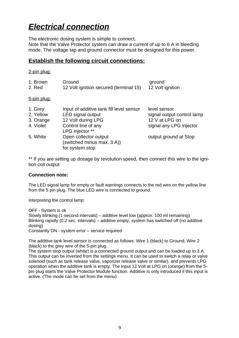
Electrical connectionThe electronic dosing system is simple to connect.Note that the Valve Protector system can draw a current of up to 6 A in bleedingmode. The voltage tap and ground connector must be designed for this power.
Establish the following circuit connections:
2-pin plug:
1. Brown Ground ground2. Red 12 Volt ignition secured (terminal 15) 12 Volt ignition
5-pin plug:
1. Grey Input of additive tank fill level sensor level sensor2. Yellow LED signal output signal output control lamp3. Orange 12 Volt during LPG 12 V at LPG on4. Violet Control line of any signal any LPG injector
LPG injector **5. White Open collector output output ground at Stop
(switched minus max. 3 A))for system stop
** If you are setting up dosage by revolution speed, then connect this wire to the igni-tion coil output
Connection note:
The LED signal lamp for empty or fault warnings connects to the red wire on the yellow linefrom the 5 pin plug. The blue LED wire is connected to ground.
Interpreting the control lamp:
OFF - System is okSlowly blinking (1-second intervals) – additive level low (approx. 100 ml remaining)Blinking rapidly (0.2 sec. intervals) – additive empty, system has switched off (no additivedosing)Constantly ON - system error – service required
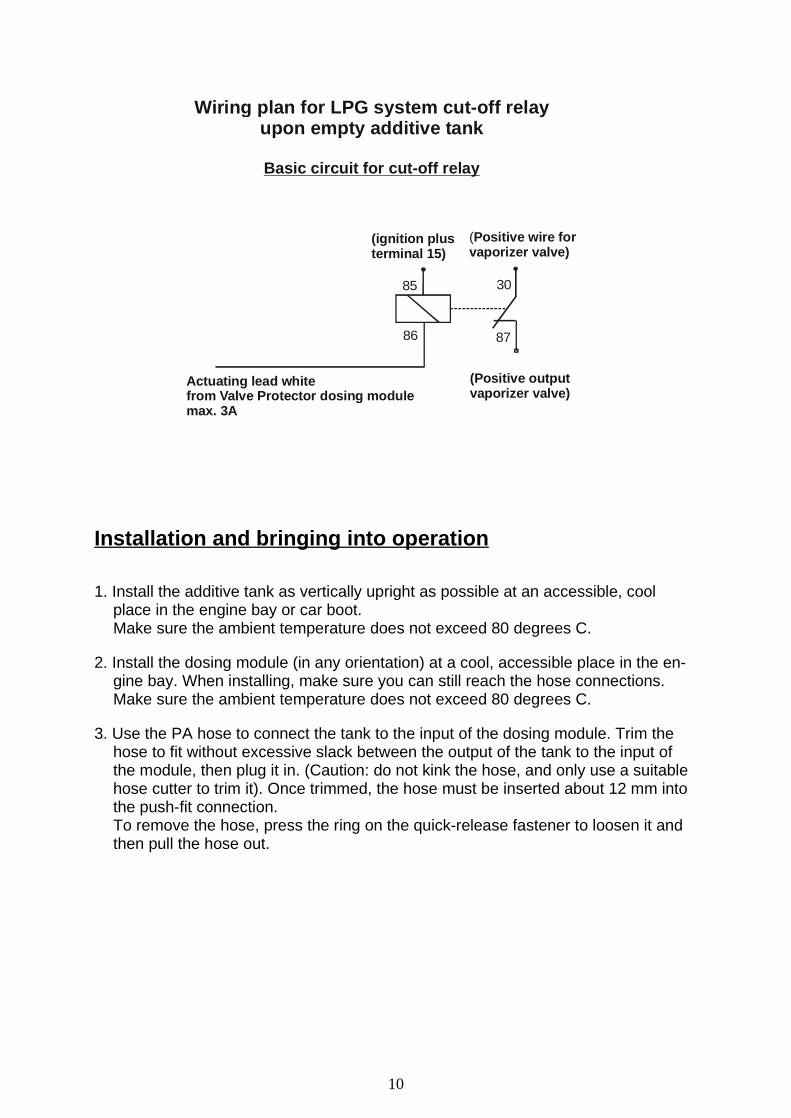
The additive tank level sensor is connected as follows: Wire 1 (black) to Ground, Wire 2(black) to the grey wire of the 5-pin plug.The system stop output (white) is a connected ground output and can be loaded up to 3 A.This output can be inverted from the settings menu. It can be used to switch a relay or valvesolenoid (such as tank release valve, vaporizer release valve or similar), and prevents LPGoperation when the additive tank is empty. The input 12 Volt at LPG on (orange) from the 5-pin plug starts the Valve Protector Module function. Additive is only introduced if this input isactive. (The mode can be set from the menu)
10
Wiring plan for LPG system cut-off relayupon empty additive tank
Basic circuit for cut-off relay
87
(Positive wire forvaporizer valve)
Actuating lead whitefrom Valve Protector dosing modulemax. 3A
(Positive outputvaporizer valve)
85 30
86
(ignition plusterminal 15)
Installation and bringing into operation
1. Install the additive tank as vertically upright as possible at an accessible, coolplace in the engine bay or car boot.Make sure the ambient temperature does not exceed 80 degrees C.
2. Install the dosing module (in any orientation) at a cool, accessible place in the en-gine bay. When installing, make sure you can still reach the hose connections.Make sure the ambient temperature does not exceed 80 degrees C.
3. Use the PA hose to connect the tank to the input of the dosing module. Trim thehose to fit without excessive slack between the output of the tank to the input ofthe module, then plug it in. (Caution: do not kink the hose, and only use a suitablehose cutter to trim it). Once trimmed, the hose must be inserted about 12 mm intothe push-fit connection.To remove the hose, press the ring on the quick-release fastener to loosen it andthen pull the hose out.

11
4. Additive feed line connections, sequential.
There are three additive feed methods to choose from.
a. Additive feed into the manifold by M5 threaded sleeve
Drill a 4.2 mm hole into the manifold beside the LPG jet.Tap an M5 thread into this hole. Screw in the additive jet, using thread sealant paste.The length of the thread can be sawn down if required. The end of the jet should nottouch the wall inside the manifold.(Caution!! No borings are allowed to get into the combustion chamber, other-wise they could cause considerable damage to the engine)Using the additive hose, connect the push-fit connector on the threaded sleeve to thecorrect output on the sequential module.Repeat this process for all cylinders.
b. Additive feed into the LPG injection hose after the LPG jet
Cut through the LPG injection hose at a suitable position after the LPG jet.Insert the additive T-piece and secure it using suitable clip collars.Using the additive hose, connect the push-fit connector of the additive shunt to thecorrect output on the sequential module. Repeat this process for all cylinders.

12
c. Additive feed for inline LPG injection with PA hose
Cut through the PA hose at a suitable position after the LPG jet.
Insert the ends of the LPG PA hose into the connections of the additive T-junction.Using the additive hose, connect the 4 mm push-fit connector of the additive shunt tothe correct output on the sequential module. Repeat this process for all cylinders.
5. Now establish all necessary electrical connections.(See wiring plan)
6. Now fill the additive tank with a suitable valve protection additive (max. 600 ml).Check the system for leaks.
7. The system bleeds itself automatically when first put into operation!!!
An air-free additive line to the sequential module is extremely important forfaultless functioning of the system. If there are any air bubbles in the additivefeed line or pump, the necessary system pressure cannot be established andmalfunctions can occur. The system therefore bleeds when it detects air bub-ble formation.Start the engine and let it idle. The system will now try to build up the necessarysystem pressure. Since there is still no additive in the pressure reservoir, after about15 seconds, the Valve Protector starts a bleeding process and draws additive. Thepositive pressure is delivered alternately to valve 1 and 2. The first time the system isoperated, and if there are long additive feed lines, it could be necessary to repeat thisprocess by switching the ignition off and on again. Once the system has bled itselfand the necessary system pressure has built up, the Valve Protector Sequential oper-ates according to the entered parameters.There should now be no air bubbles left in the additive feed lines from the additivetank to the module. It is normal for air bubbles to form after the distributor module inthe direction of the points of introduction, and this is not a fault.
Caution: Additives can cause damage to rubber or plastic parts.Immediately rinse off any escaping additive with plenty of water.

13
8. Use the programming cable on the dosing module to connect it to the USB port onyour laptop or PC system.Switch the ignition on – and now start the Valve Protector program.The Connect indicator on the Valve Protector monitor should now display the connec-tion to the dosing module
9. Now set the appropriate parameters for the vehicle in the Valve Protector program.Tips about the correct settings are given in the right field of the program.
10. While the engine is running on LPG, observe the live screen and check that it isfunctioning correctly. While the vehicle is LPG-fuelled, the injection timing monitorshould display the current injection timings of the connected jets. The pump activitymonitor should then fill up towards 100 %.When 100 % is reached, an additive dosage is triggered and the pulse monitor resetto 00. An additive dose should be made into the idle LPG mixture every 20–180 sec-onds, depending on the engine characteristics.The next activated cylinder will also be displayed.
11. The system is now fully installed and ready for operation.
Note
The quantity of additive withdrawn should be inspected after about 1000 kilometreshave been driven on LPG. Always observe the additive manufacturer’s instructionsregarding the correct dosage.
If the amount of dosed additive is too high or too low, then decrease or increase thevalue ‘Dosage’ in the Settings program window.
The specified durabilities and applications are only “reference values” and do not ab-solve the customer of his responsibility to perform his own tests or evaluation of thesuitability for the application.Please note that elastomers have a limited service life, e.g. due to aging. We there-fore recommend regular inspection and change intervals.All information provided is correct to the best of our knowledge. We make noguarantee, however, as to the correctness and completeness of this information.

14

15
Quick start instructions – Amount settingAdditonal to the PC-ProgrammingThe Electronic Valve Protector module is equipped with atouch sensor (chrome ring). This metallic chrome ring reactsto touch by finger – just like a button. On the left side wall ofthe module, an LED is installed, which indicates the variousfunctions with three colours (red-green-yellow) (see the following installationinstructions).
Step 1: Start the vehicle and activate gas operation. The dosing module is now provided with power and remainsin Set-up ready mode (LED lights up yellow) for 30 seconds.
Step 2: While the yellow LED is on, touch the metallic chrome ring with your finger until the LED lights upgreen. Then remove your finger.
Step 3: The LED now flashes x times and indicates the set amount of cylinders. You canset between 1 and 16 cylinders. To change the number of cylinders, simply tap onchrome ring with your finger until you have reached the required number or cylinders. Theflash display will always show the number of cylinders set. Once level 16 has been reached, counting starts againat 1. (Factory setting 4 cylinders)
Step 4: Once you have set the required number of cylinders, hold down your finger on the chrome ring until theLED light is red. You are now in the setting menu for dosage level setting.
Step 5: The LED now flashes x times red and displays the set dosage level. There are15 dosage levels and one level for a quick test run. (Attention: Do not run test runexcessively as otherwise too much additive is fed-in). Check the guide level table at theend of this page for the correct dosage level for your vehicle. (Factory setting level 9)To change the dosage level simply tap on to the chrome ring with your finger until the required dosage level isreached. The flash display always shows the set dosage level. After level 16, counting starts again at level 1.
Step 6: Once you have reached the desired dosage level, (see required number of flashes), touch the tubeconnection until the LED light is yellow. For venting of the module the pump can switch on or off by pressingthe chrome ring.
Step 7: Once you have reached the desired dosage level, (see required number of flashes), touch the chromering until the LED light is green. The settings are now stored and the module is in operation mode. The moduleremains in set-up ready mode (LED yellow) following each restart. If during this phase, the chrome ring is nottouched, the module automatically changes into working mode (LED green) after 30 seconds. The setting Table isonly a guide! The correct dosage must be checked after each installation and adjusted if required.
Display of LED built-in module
LED light is green: System has operating voltage but is not receiving control impulses from the gas injector.LED flashes green: System has operating voltage and is receiving control impulses from the gas injector
(operating mode)LED slowly flashes red (every second): no input from level sensor into additive tankLED quickly flashes red (every 0.25 sec.): additive depletedLED flashes yellow (every 0.5 sec.): additive is being injected
Display of LED to be installed in passenger area
LED flashes 3 times for operation control. power on controlLED flashes slowly (every second): remaining additive level reserve approx. 100 mlLED flashes quickly (every 0.25 sec.): additive depleted.
Guide level table for base amount setting per Cylinder
Level 1 2 3 4 5 6 7 8 9 10 11 12 13 14 15 16Cylinder capacity KW 4 5 7 8 10 13 16 20 26 32 40 56 64 80 112 Test
Cylinder capacity PS 5 7 10 11 14 18 22 27 35 43 54 76 87 108 152 Test
(Werkseinstellung 4 Zyl.)
(Werkseinstellung. Stufe 9)
16
Safety NoticesIntended use:
Valve Protector is an electronically controlled dosing unit comprising thefollowing components:1. Additive tank, 2. Electronically controlled dosing module, 3. Feed line connection,4. PA hose
The intended use is for dosing suitable and approved additives in internalcombustion engines.Valve Protector has been developed and constructed in accordance withprevailing safety guidelines.
It may only be used under the following conditions:
1. In technically faultless condition2. After careful leak testing3. Having been installed and brought into operation by a skilled professional4. Used only for the intended purpose5. Failure to observe the safety notices can lead to personal injury and material damage6. Electrical lines and additive lines must always be laid in such a way as to rule out da-
mage and chafing7. Observe the additive manufacturer’s safety guidelines8. Compatibility between the additive and the components through which it flows has been
checked and confirmed9. Check for correct dosage at regular intervals10. In the case of over/underdosage, have the system checked in an authorized service cen-
tre.11. Driving with incorrect dosages can cause damage to your engine and/or exhaust system.12. Rinse off any spilt additive with plenty of water13. Refill the additive tank level when it gets low14. Do not fill above the fill line15. Never mix different additives16. Use only approved and authorized additives17. Using unauthorized additives can forfeit your operating licence18. Use only original replacement parts19. The specified durabilities and applications are only “reference values” and do not absolve
the customer of his responsibility to perform his own tests or evaluation of the suitabilityfor the application. Please note that elastomers have a limited service life, e.g. due toaging. We therefore recommend regular inspection and change intervals. All informationprovided is correct to the best of our knowledge. We make no guarantee, however, as tothe correctness and completeness of this information.
20. The warranty period is 24 months from the date of purchase (against presentation of thesales slip or invoice). The warranty becomes void in the case of improper use of the de-vice, use outside the technical specifications, use of an unapproved additive, improperoperation or unauthorized interference. We are not liable for any damage resulting fromthese cases.The exemption from liability also extends to all services performed by third parties thathave not been ordered in writing by us.

17
Technical Data:Power supply: 12V DC (10V–15V)Current draw: Idle 30 mA , Pump stroke up to 6 APump pressure, max.: 5 BARPump volume/stroke: 50 μl additiveMax. power: 180 ml/hWeight: 1,250 gDimensions L/W/H: 145 mm x 95 mm x 56 mmDevice installation orientation: AnyTemperature range: -20/+85°CProtection class: IP54Sealing materials: FKM (Viton) / Elastomer with high temperature and weath-
ering resistance. Suitable for many acids, bases, fuelsand oils (including synthetic).
EC Declaration of Conformitypursuant toAnnex I to the EC Directiveon Electromagnetic Compatibility2004/108/ECSI-Elektronik GmbH declares thatProduct name: Valve Protector SequentialType: VP40127-SYear of manufacture: 2009conforms to the regulations of the abovementioned EC Guidelines.