technical manual nilar energy storage€¦ · industrial energy storage and battery solutions that...
TRANSCRIPT
Nilar Energy StorageHigh power industrial energy storage and battery solutions that are safe and environmentally friendly
Technical manual
NiMH bi-polar battery technology
E
B
A
D
C
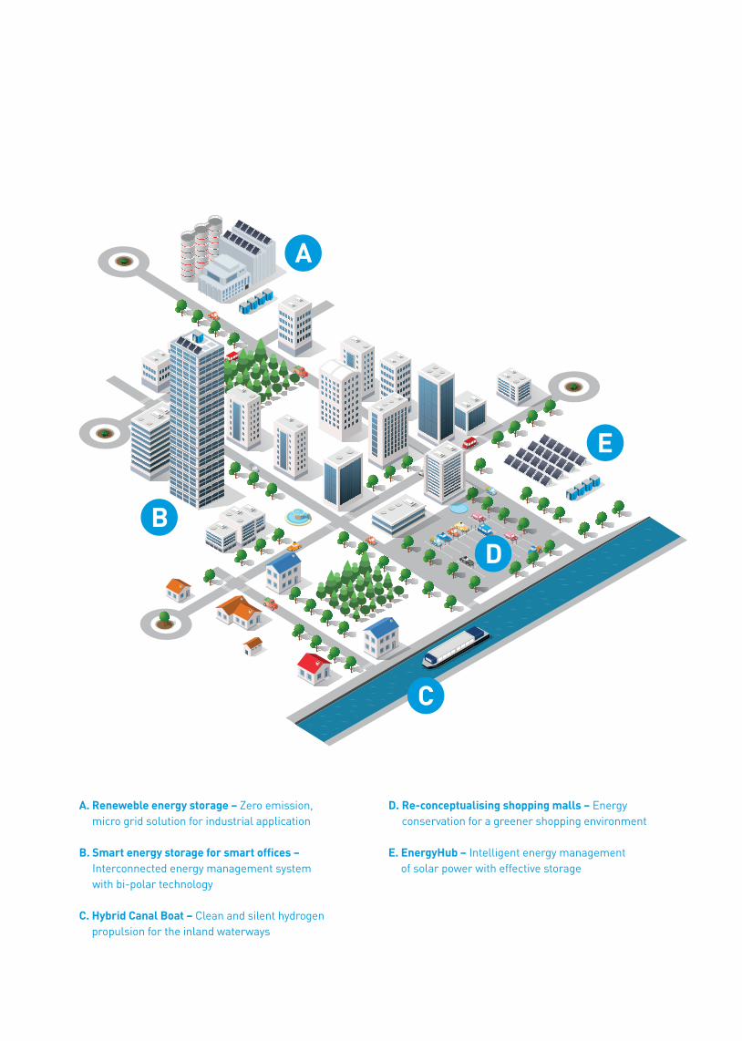
A. Reneweble energy storage – Zero emission, micro grid solution for industrial application
B. Smart energy storage for smart offices – Interconnected energy management system with bi-polar technology
C. Hybrid Canal Boat – Clean and silent hydrogen propulsion for the inland waterways
D. Re-conceptualising shopping malls – Energy conservation for a greener shopping environment
E. EnergyHub – Intelligent energy management of solar power with effective storage

3
Nilar batteries and energy storages . . . . . . . . . . 4
The 12 V Energy Module . . . . . . . . . . . . . . . . . . . . . 6
Solutions and applications . . . . . . . . . . . . . . . . . . 5
Nilar battery pack features . . . . . . . . . . . . . . . . . . 7
Operating features . . . . . . . . . . . . . . . . . . . . . . . . . 8 Discharging. . . . . . . . . . . . . . . . . . . . . . . . . . . . . . 8 Charging . . . . . . . . . . . . . . . . . . . . . . . . . . . . . . . 10 Self discharge . . . . . . . . . . . . . . . . . . . . . . . . . . . 11 Cycle life . . . . . . . . . . . . . . . . . . . . . . . . . . . . . . . 11
15-pin signal connector . . . . . . . . . . . . . . . . . . . . 11
Transport . . . . . . . . . . . . . . . . . . . . . . . . . . . . . . . . 14
Disposal . . . . . . . . . . . . . . . . . . . . . . . . . . . . . . . . . 15
Design . . . . . . . . . . . . . . . . . . . . . . . . . . . . . . . . . . 16 Pack design . . . . . . . . . . . . . . . . . . . . . . . . . . . . 17 Modular design . . . . . . . . . . . . . . . . . . . . . . . . . 18
Electrochemistry . . . . . . . . . . . . . . . . . . . . . . . . . 20
Nilar high voltage energy storage solutions . . . 22
Features . . . . . . . . . . . . . . . . . . . . . . . . . . . . . . . . . 23
Nilar high voltage energy storage systems. . . . 24 System overview. . . . . . . . . . . . . . . . . . . . . . . . . 24 Nilar High Voltage BMS . . . . . . . . . . . . . . . . . . . 25
Configuration . . . . . . . . . . . . . . . . . . . . . . . . . . . . . 26
Installation. . . . . . . . . . . . . . . . . . . . . . . . . . . . . . . 27
Nilar system components . . . . . . . . . . . . . . . . . . 28 Battery packs . . . . . . . . . . . . . . . . . . . . . . . . . . . 28 Monitoring unit . . . . . . . . . . . . . . . . . . . . . . . . . . 28 Programmable logical controller (PLC) . . . . . . 29 Circuit breaker . . . . . . . . . . . . . . . . . . . . . . . . . . 29 Fuse . . . . . . . . . . . . . . . . . . . . . . . . . . . . . . . . . . 29 Current sensor . . . . . . . . . . . . . . . . . . . . . . . . . . 29
Nilar low voltage battery systems . . . . . . . . . . . 30
Features . . . . . . . . . . . . . . . . . . . . . . . . . . . . . . . . . 31
Nilar low voltage battery solutions . . . . . . . . . . 32 System overview. . . . . . . . . . . . . . . . . . . . . . . . . 32 Nilar Low Voltage BMS . . . . . . . . . . . . . . . . . . . 33
Configuration . . . . . . . . . . . . . . . . . . . . . . . . . . . . . 34
Installation. . . . . . . . . . . . . . . . . . . . . . . . . . . . . . . 35
Battery pack range . . . . . . . . . . . . . . . . . . . . . . . . 37
Low Voltage BMS . . . . . . . . . . . . . . . . . . . . . . . . . 38 Interface connectors . . . . . . . . . . . . . . . . . . . . . 40
Chargers . . . . . . . . . . . . . . . . . . . . . . . . . . . . . . . . 41
Contents

4
Nilar provides customers with low and high voltage industrial energy storage and battery solutions that are safe and environmentally friendly. Solutions are built on modular and flexible battery packs based on the Nilar battery energy module and integrated, easy-to-use battery management systems for high and low voltage systems.
Nilar batteries and energy storages

5
Simple to use low voltage battery solutions: • Wheelchairs• Automatic guided vehicles (AGV)• Cleaning equipment• Go-carts• Telecom• Solar power• Boat drive train
Nilar bipolar batteries deliver unrivalled industrial power solutions for a number of applications across a wide range of market segments. By combining the modular and flexible Nilar battery module and integrated battery management systems, Nilar can serve customers with:
• Simple to use low voltage battery solutions• Advanced high voltage energy storage needs
Nilar provides dedicated battery management systems for modular charging of serial and parallel configurations in low voltage systems (12-24-36-48 V) and local monitoring units for high voltage systems (60-720 V). For specific applications, when the customer wants to integrate their own battery management systems, Nilar will provide algorithms and settings in cooperation with the customer.
Advanced high voltage energy storage:
• Solar and wind power• Uninterruptible power supply & telecom• Smart grid / grid support• Marine – electric ferries• EV – charging
Solutions and applications
6
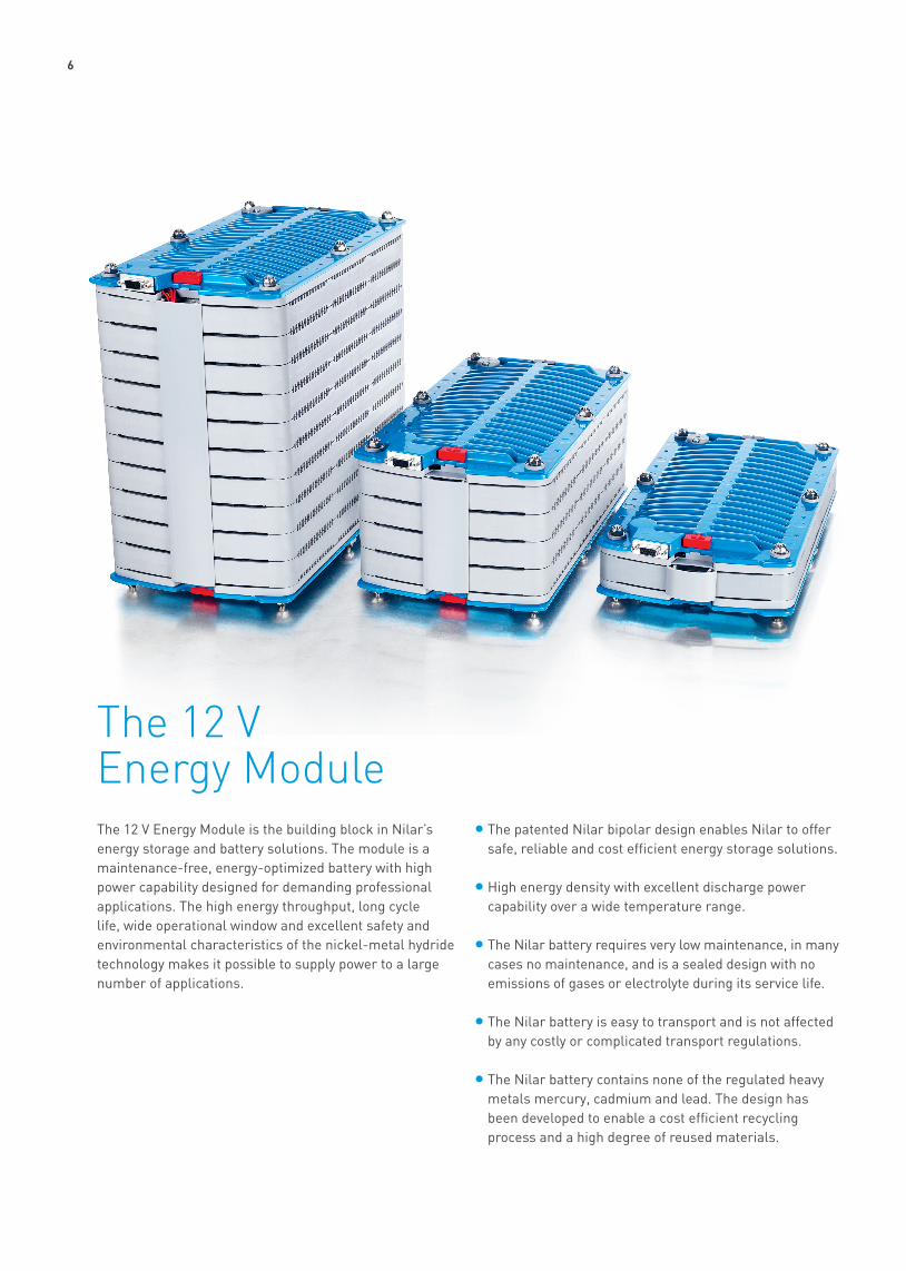
The 12 V Energy Module is the building block in Nilar’s energy storage and battery solutions. The module is a maintenance-free, energy-optimized battery with high power capability designed for demanding professional applications. The high energy throughput, long cycle life, wide operational window and excellent safety and environmental characteristics of the nickel-metal hydride technology makes it possible to supply power to a large number of applications.
• The patented Nilar bipolar design enables Nilar to offer safe, reliable and cost efficient energy storage solutions.
• High energy density with excellent discharge power capability over a wide temperature range.
• The Nilar battery requires very low maintenance, in many cases no maintenance, and is a sealed design with no emissions of gases or electrolyte during its service life.
• The Nilar battery is easy to transport and is not affected by any costly or complicated transport regulations.
• The Nilar battery contains none of the regulated heavy metals mercury, cadmium and lead. The design has been developed to enable a cost efficient recycling process and a high degree of reused materials.
The 12 V Energy Module

7
Nominal voltageThe cell voltage of a battery cell is governed by the electrochemical potentials of the active materials used in the negative and positive electrodes and the electrolyte. For the nickel-metal hydride system used in Nilar battery packs, the nominal cell voltage is 1.2 V. The smallest units in a Nilar battery pack are the 12 V modules with 10 cells assembled in series. Modules in a pack and packs are connected in series to achieve a nominal battery voltage in multiples of 12 V.
Rated capacity The battery capacity is rated in ampere-hours (Ah) and denotes the quantity of electricity a fully charged battery can deliver at a 5 h discharge to 1 V per cell at +20 °C. Modules have a capacity rating of 10 Ah. Modules in a pack and packs are connected in parallel to achieve rated battery capacity in multiples of 10 Ah.
Operating voltageTypical cell operational voltage is 1.6 V during charge to 1 V per cell at discharge corresponding to 16 to 10 V for a 12 V module.
Operating temperaturesThe batteries can be operated in temperatures from -20 °C to +50 °C.
Intermediate state of chargeBatteries can be stored or operated at an intermediate state of charge without loss of performance.
InstallationThe design is a sealed design. At normal operating conditions Nilar battery packs do not produce any emissions and require no forced ventilation to remove flammable gases generated during operation of the battery.
ReliabilityThe Nilar battery is a stable electrochemical system regarding structural integrity of its components. There is no corrosion of components resulting in premature and unpredictable critical damage to the battery or any type of sudden death. The design is shock and vibration resistant. The end-of-life characteristics of Nilar battery packs display a graceful decline in performance over the life of packs.
StorageNilar battery packs can be stored several years without loss of performance.
MaintenanceNilar battery packs use a sealed design that requires a minimum of maintenance, for many applications no maintenance at all is required.
Nilar battery pack features

8
DischargingDischarge performance After a moderate initial voltage drop the discharge voltage is stable over more than 80 % of the discharge and ends with a distinct knee at end of the useful capacity. Discharge voltage is dependent on discharge rate, temperature and the state of charge. The discharge voltage decreases with increased discharge rates and decreasing temperature. The discharge performance is affected moderately at elevated temperatures but at low temperatures the effect of temperature on discharge performance is more pronounced, mainly due to the increase in resistance at low temperatures. The discharge capacity, or the run-time to end of discharge, is mainly affected by discharge rate and temperature. Delivered capacity depends on the selected discharge cutoff voltage and decreases with increasing discharge cutoff voltage.
Test currents in this manual are expressed as multiples of the rated capacity value denoted by C. E.g. a discharge current of 2C for a Nilar battery pack with a rated capacity of 10 Ah equals 20 A.
Figure 1. Typical voltage profiles for constant current discharges with various discharge rates. Charging and discharging made at +20 °C.
15
14
13
12
11
10
9
8
0.2C
0.5C
1C
2C
3C
0% 20% 40% 60% 80% 100%Capacity
Volt
age
[V]
Figure 2. Constant current discharge with 0.2C at various temperatures. The battery was fully charged at +20 °C, acclimatized for 12 h at test temperature and then discharged.
15
14
13
12
11
10
9
8
40 °C
20 °C
0 °C
-20 °C
0% 20% 40% 60% 80% 100%Capacity
Volt
age
[V]
Operating features
9
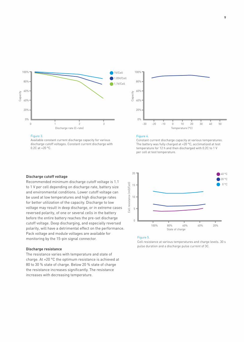
Figure 3. Available constant current discharge capacity for various discharge cutoff voltages. Constant current discharge with 0.2C at +20 °C.
100%
80%
60%
40%
20%
0%
100%
80%
60%
40%
20%
0%
1V/Cell
1.05V/Cell
1.1V/Cell
0 -30 -10-20 10 20 400 30 501 2 3Discharge rate (C-rate) Temperature (°C)
Cap
acity
Cap
acity
Figure 4. Constant current discharge capacity at various temperatures. The battery was fully charged at +20 °C, acclimatized at test temperature for 12 h and then discharged with 0.2C to 1 V per cell at test temperature.
Figure 5. Cell resistance at various temperatures and charge levels. 30 s pulse duration and a discharge pulse current of 3C.
20
15
10
5
0
40 °C
20 °C
0 °C
State of charge
Cel
l res
ista
nce
(mΩ
/Cel
l)
Discharge cutoff voltageRecommended minimum discharge cutoff voltage is 1.1 to 1 V per cell depending on discharge rate, battery size and environmental conditions. Lower cutoff voltage can be used at low temperatures and high discharge rates for better utilization of the capacity. Discharge to low voltage may result in deep discharge, or in extreme cases reversed polarity, of one or several cells in the battery before the entire battery reaches the pre-set discharge cutoff voltage. Deep discharging, and especially reversed polarity, will have a detrimental effect on the performance. Pack voltage and module voltages are available for monitoring by the 15-pin signal connector.
Discharge resistanceThe resistance varies with temperature and state of charge. At +20 °C the optimum resistance is achieved at 80 to 30 % state of charge. Below 20 % state of charge the resistance increases significantly. The resistance increases with decreasing temperature.
100% 80% 60% 40% 20%
10
ChargingNilar charging systemsNilar battery packs require optimized charge procedures and charge settings to ensure performance and service life. Constant current chargers modified to enable control from the Nilar charging system are required. Packs with modules connected in series, with a rated pack capacity of 10 Ah, can be charged with constant current chargers with specific charge termination settings that are based on pack temperature, pressure and terminal voltage. In parallel configurations packs have to be charged with electronic charge control systems controlling individual modules in the pack. The electronic charge systems offered by Nilar can be used with both serial and parallel pack configurations.
Charging with chargers and charge settings not approved by Nilar will void warranties and may damage the battery.
For specific applications, where the customer wants to integrate their own battery management systems, Nilar will provide algorithms and settings in cooperation with the customer. The following specified charge procedures and settings are presented as general charge recommendations. If the electronic charging systems developed by Nilar are not to be used please contact Nilar for detailed information on charge procedures and settings.
Low Voltage BMS • Packs with modules in series and parallel configurations• Low voltage systems 12 – 48 V• Controls charging on module level • Communicates with Nilar approved chargers to regulate
charge power
High voltage BMS • High voltage system 60 – 720 V• Communication interface with charge settings, alarm
signals and pack status indicators for large format energy storage systems
• Communicates with main control system through Programmable Logic Controller (PLC)
Recommended charge procedureThe recommended charge procedure is constant current charge with charge termination based on rate of temperature increase (dT/dt) together with a maximum allowed pressure and pack temperature. The recommended charge rate is 0.3C to dT/dt corresponding to 0.3 °C in 2 minutes. The charge procedure can be used for charging battery packs with battery pack temperature in the range of -20 °C to +40 °C. Maximum allowed pressure is 586 kPa corresponding to 85 PSI. Charging shall be terminated when the battery pack temperature reach +60 °C. A deep discharged battery pack is recharged in less than 3.5 h.
An inherent feature of the NiMH electrochemical system at constant current charging is the build-up of pressure and temperature at the end of the charge. It is therefore important to use a correct charge method to ensure sufficient performance. At low temperatures the charge rate can be limited by an increased voltage needed to charge the battery. At elevated temperatures the maximum charge rate is limited by the rise in temperature and pressure at end of charge.
For a battery in service the cells in the battery will with time reach various charge levels due to temperature gradients in the battery causing small variations in self discharge rate and impedance. The result is reduced run-time and, in extreme cases, accelerated ageing of the battery due to deep discharge of the low capacity cells in the battery. Balancing of cells in Nilar battery packs can be achieved simply by a limited overcharge allowing the low capacity cells to become fully charged. Heat generated at overcharge is detrimental to the performance and have to be considered in the charge design. Cell balancing is included in the electronic charge solutions provided by Nilar.
11
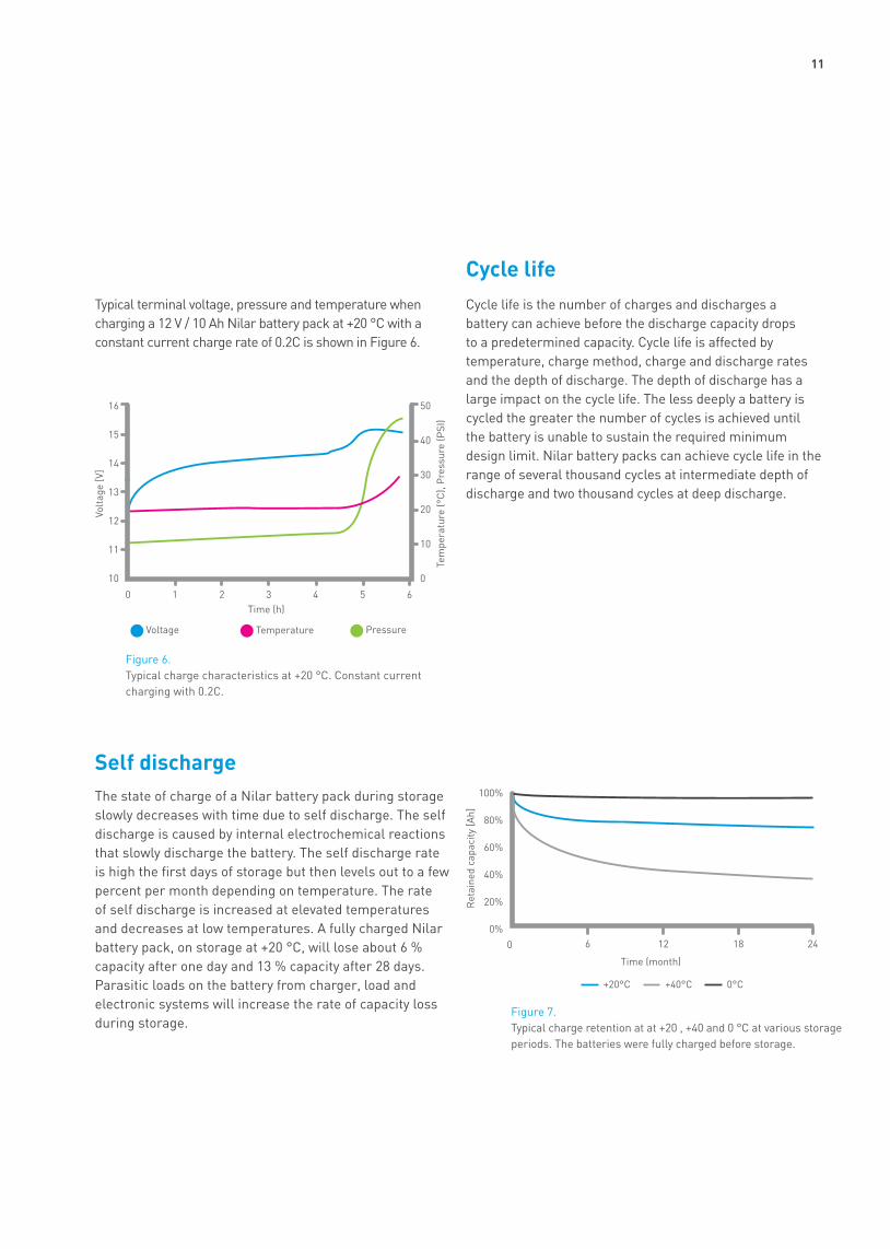
Cycle lifeCycle life is the number of charges and discharges a battery can achieve before the discharge capacity drops to a predetermined capacity. Cycle life is affected by temperature, charge method, charge and discharge rates and the depth of discharge. The depth of discharge has a large impact on the cycle life. The less deeply a battery is cycled the greater the number of cycles is achieved until the battery is unable to sustain the required minimum design limit. Nilar battery packs can achieve cycle life in the range of several thousand cycles at intermediate depth of discharge and two thousand cycles at deep discharge.
Self dischargeThe state of charge of a Nilar battery pack during storage slowly decreases with time due to self discharge. The self discharge is caused by internal electrochemical reactions that slowly discharge the battery. The self discharge rate is high the first days of storage but then levels out to a few percent per month depending on temperature. The rate of self discharge is increased at elevated temperatures and decreases at low temperatures. A fully charged Nilar battery pack, on storage at +20 °C, will lose about 6 % capacity after one day and 13 % capacity after 28 days. Parasitic loads on the battery from charger, load and electronic systems will increase the rate of capacity loss during storage.
Typical terminal voltage, pressure and temperature when charging a 12 V / 10 Ah Nilar battery pack at +20 °C with a constant current charge rate of 0.2C is shown in Figure 6.
Figure 7. Typical charge retention at at +20 , +40 and 0 °C at various storage periods. The batteries were fully charged before storage.
Time (month)
0 6 12 18 24
100%
80%
60%
40%
20%
0%
Ret
aine
d ca
paci
ty [A
h]
+20°C +40°C 0°C
Figure 6. Typical charge characteristics at +20 °C. Constant current charging with 0.2C.
16
15
14
13
12
11
10
50
40
30
20
10
0
Voltage Temperature Pressure
Time (h)
Volt
age
[V]
Tem
pera
ture
(°C
), P
ress
ure
(PSI
)
0 1 2 3 4 5 6

12
The connector for monitoring of module voltages, pack pressure and pack temperature is of type D-SUB with 15 poles and with the female socket mounted in the end-piece. To translate the pressure signal in Volt to pressure in bar equation 1 is used. U is measured DC-voltage between pin 10 and pin 15 when an external voltage of +5 V (DC) is applied between pin 5 and pin 15.
Figure 11. Connection of the D-SUB connector to the battery.
D-SUB pin configuration
1. Module 8 Voltage Tap2. Module 5 Voltage Tap3. Module 2 Voltage Tap4. Temperature signal5. +5 V Signal power6. Module 10 Voltage Tap7. Module 7 Voltage Tap8. Module 4 Voltage Tap
9. Module 1 Voltage Tap10. Pressure signal11. Module 9 Voltage Tap12. Module 6 Voltage Tap13. Module 3 Voltage Tap14. Negative Terminal Voltage Tap15. Signal GND
12345
678910
1112131415
Equation [1] p = 2.5 * U - 1.25 [bar] 1 bar ≈ 14.5 psi. 1 bar = 100 kPa
15-pin signal connector

13

14
One of the advantages with Nilar battery packs, as compared with many other battery types and especially Li ion batteries, is that UN approved packaging and marking is not required for transport by sea, road, rail and air.
No dangerous goods documentation is required when transporting Nilar battery packs by road or rail.
A dangerous goods declaration is required if batteries are transported by sea in quantities of over 100 kg in one transport unit. Nilar battery packs are then defined as dangerous goods, class 9. UN number and Proper Shipping Name are UN 3496 and Batteries, Nickel-Metal Hydride respectively.
An Air Waybill or similar is required if batteries are transported by air. Nilar battery packs are not classified as dangerous goods and belong to the entry “Batteries, dry” in the list of dangerous goods in IATA (no UN number). If an Air Waybill is used, the words ”Not Restricted” and the Special Provision number (A123) must be included in the description of the substance on the Air Waybill, according to IATA-DGR.
The safety precaution that all battery types, including Nilar battery packs, must fulfill in transportation is that the batteries must be separated from each other to prevent short-circuits and be securely packed to prevent movement that could lead to short-circuits. Terminals should be effectively insulated.
Terminal cover
In the case of transport in equipment, the battery must be disconnected and exposed terminals must be protected from short-circuits.
Please observe that special regulations apply for defective or damaged batteries that have the potential of leading to a hazardous event during transportation. Please contact local expertise or Nilar for advice regarding transport of damaged or defective batteries.
Transport

15
Environmental protection is highly prioritized by Nilar, starting at the design and development of new products, during production and process development, to end-of-life collection, disposal, and recycling. Nilar continuously works to improve all stages of the battery’s life cycle with the aim to minimize environmental impact. Nilar stays in the front line of recycling technology by participating in different research programs for recycling. The pack design is optimized for a high level of recycling of the materials and to enable cost efficient recycling processes.
In Europe handling of battery waste is regulated according to Battery directive 2006/66/EC and EU Member state national legislation. Nilar takes full responsibility for taking back our batteries and for the recycling process of our batteries. Returned batteries are systematically recycled and the materials are re-used either in new batteries or in other industries.
When your Nilar battery is ready for disposal it is recommended to send the battery to the local Nilar battery dealer or to Nilar Svenska AB.
The battery must be protected from short-circuiting during transport. Please see section regarding transport.
Never incinerate or dispose of Nilar battery packs as landfill.
Disposal
16
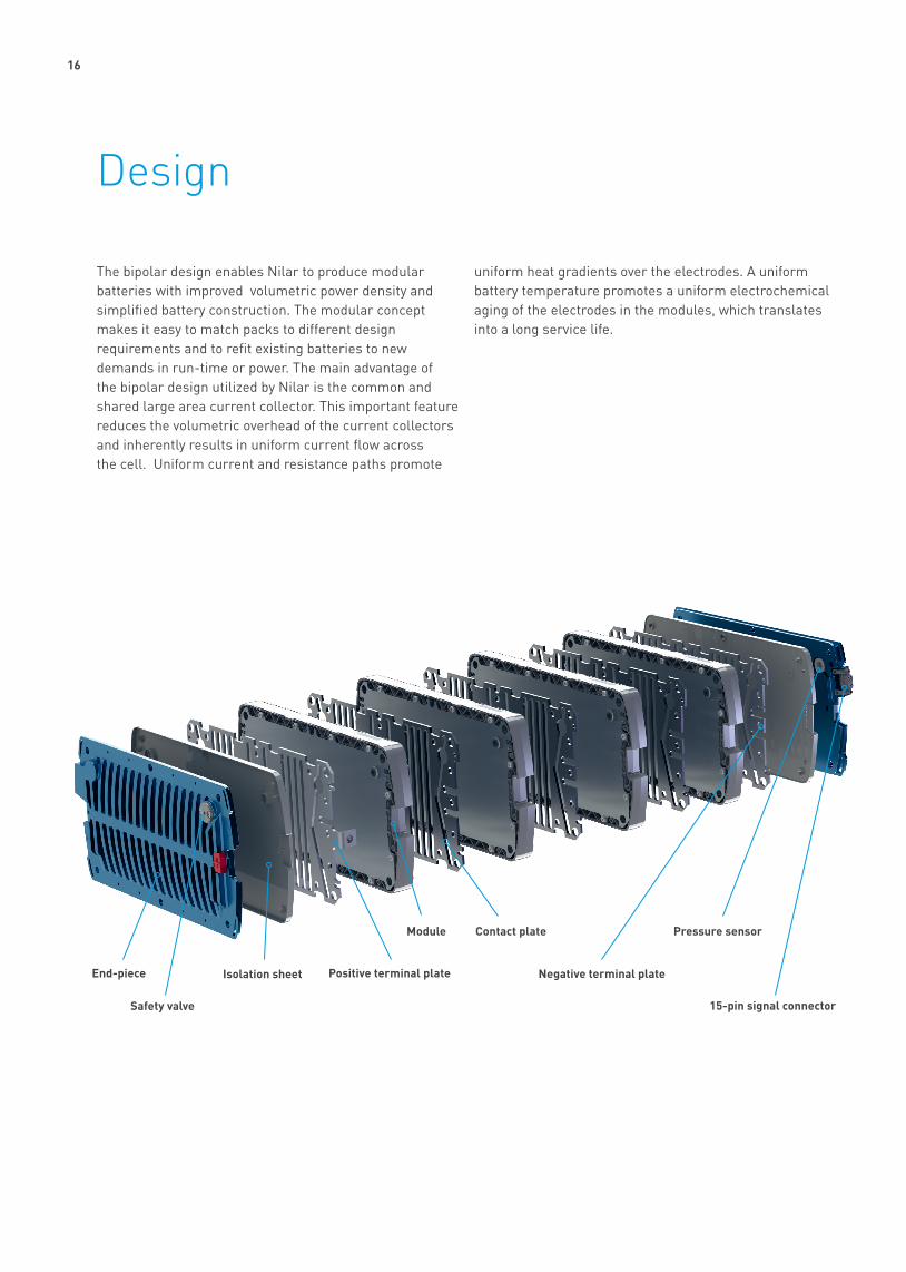
The bipolar design enables Nilar to produce modular batteries with improved volumetric power density and simplified battery construction. The modular concept makes it easy to match packs to different design requirements and to refit existing batteries to new demands in run-time or power. The main advantage of the bipolar design utilized by Nilar is the common and shared large area current collector. This important feature reduces the volumetric overhead of the current collectors and inherently results in uniform current flow across the cell. Uniform current and resistance paths promote
uniform heat gradients over the electrodes. A uniform battery temperature promotes a uniform electrochemical aging of the electrodes in the modules, which translates into a long service life.
Design
End-piece
Safety valve
Isolation sheet Positive terminal plate
Contact plateModule
Negative terminal plate
Pressure sensor
15-pin signal connector

17
Pack designThe pack design achieves a compact assembly of cells and other components required in a battery pack to meet required system voltage and run-time. A typical pack consists of 12 different types of components, assembled to a pack by a pick and place manufacturing process, followed by electrolyte filling and formation by a few cycles of charging and discharging to activate the electrochemical system in the cells.
End-pieceThere is one end-piece on each side of the pack connected with tie-rods to assure the required cell compression. Besides providing uniform cell compression over the electrode surfaces they also provide impact protection to the modules.
Safety valveNilar battery packs are fitted with one pressure valve per pack with an opening pressure of 689 kPa corresponding to 100 psi. The pressure valve is located on the end-piece with the positive terminal pillar marking. The pressure valve is only activated at abusive conditions.
Isolation sheetThe isolation sheet insulates the end-pieces from the pack voltage potential.
Terminal plateThe terminal plate is a contact plate with an integrated terminal pillar for connecting power cables to the pack. There is one positive and one negative terminal plate per pack. The terminal connector design of Nilar battery packs does not require any means of sealing between terminal and container to maintain the integrity of the electrochemical system within the cells. The design eliminates the risk of electrolyte or gas leakage through any terminal sealing.
Contact plateThe contact plate electrically connects the adjacent modules in the pack and thus eliminates the need for external connectors between modules. The design of the contact plate allows for efficient active air cooling in demanding high power applications.
ModuleModules with a rated capacity of 10 Ah are the building blocks for all Nilar battery packs. 15-pin signal connector Connector for monitoring analog signals for pack and module voltages, pack pressure (common for all cells in the pack) and pack temperature.
Design

18
Modular designThe modules are the building blocks of all packs offered by Nilar. The modules are manufactured in a fully automated pick and place manufacturing process with binders and volatile organic solvents eliminated in the process. The high quality of the modules is an inherent feature of the patented Nilar bipolar design and the state-of-the-art manufacturing process.
EPDM bushing
Biplate
Electrodes
Separator Contact plate ModuleGasket CaseCell

19
ElectrodesThe positive and negative electrodes are manufactured by a patented method for compression of dry powders without any expensive plate support material, binders or volatile organic solvents. Active materials and additives, as dry powders, are mixed with each other before being compressed in a calendar system to form continuous sheets of compressed electrode material. The sheets of active materials are cut into electrode plates. The electrode manufacturing process yields very low deviations in electrode plate dimensions, weight and capacity and are one of the main contributions to the high quality of Nilar battery packs.
SeparatorThe separator prevents electrical contact between the positive and negative electrodes in the cell while holding the electrolyte necessary for ionic transport. The separator consists of a non-woven, melt-blown, acrylic acid-grated polyolefin.
ElectrolyteThe electrolyte is a solution of potassium hydroxide and lithium hydroxide. The design is a so called starved electrolyte design with no free volume of electrolyte in the cells. All of the electrolyte volume is absorbed by the positive and negative electrodes and in the separator. The electrolyte will maintain its function over the service life of the battery and does not need to be replaced or adjusted.
BiplateThe biplates, together with the gaskets, are the means for sealing each cell. The biplates also provide electrical contact between cells. The biplates are made of thin nickel foil. Each biplate is provided with an opening to enable electrolyte filling.
GasketEach cell is surrounded by a gasket. The gasket together with the biplates provide a seal between the interior of the cell and the exterior. The hydrophobic properties of the gasket prevent the creation of electrolyte bridges between adjacent cells. Each gasket is provided with an opening to enable electrolyte filling.
CaseThe case provides impact protection to the cells in the module and prevents the gaskets from being deformed by the cell pressure. The case is made of injection molded polyamide. Openings are provided in the case for the tie rods connecting the end-pieces.

20
H
H
H
H
HH
Oh-
H2O
H
H
Negative electrode Electrolyte Positive electrode
Charger or loadDischarge
e-
e-
Charge
( - ) ( + )
Ni OHOH
Ni OHOH
Ni OHOH
Figure 12. Electrochemical principle.
M
M
M
M
M
M
M
M
M
M
M
M
Electrochemistry

21
The Nilar battery would commonly be referred to as a rechargeable nickel metal hydride (NiMH) battery. We also refer to it as a hydrogen or H-battery, due to its close overall similarity to Li-batteries. In H- and Li-batteries, hydrogen or lithium atoms, respectively, move between the electrodes when the cells are charged and discharged. In a charged H-battery, hydrogen atoms are stored in a metal alloy constituting the anode. When the cells are discharged these hydrogen atoms are transferred to the cathode via the electrolyte in the form of water molecules. The chemical energy is essentially contained in an oxygen hydrogen bond.
One major difference between the chemistries is the possibility to include a chemically based overcharge and overdischarge protection in the H-battery. This is a consequence of a water based electrolyte and that hydrogen can form gaseous hydrogen molecules and be transported in the gas space between the electrodes. When the H-battery is overcharged oxygen gas will form at the positive electrode by splitting water molecules at the cathode. In Nilar’s design, this oxygen gas can pass through the separator and be recombined again to water at the anode electrode. Thus, no net reaction takes place, but the energy input will result in increased temperature and pressure. These can be monitored and used to terminate charging. Similarly, during overdischarge hydrogen gas will evolve at the cathode but again it can be recombined to water at the anode – again resulting in heat generation and a pressure increase but no net reaction. In extreme cases of overcharge and overdischarge the recombination reaction will not be able to reduce the pressure and the safety valve will open to reduce pressure and avoid cell rupture. The cell voltage allows for a water-based electrolyte to be used. The Grotthus hydrogen hopping mechanism between water molecules in water, gives water-based electrolytes superior conductivity. This adds to safety as the electrodes can be kept well separated by robust separators.
Electrochemistry

22
Nilar high voltage energy storage solutionsNilar offers high power battery solutions that are easy to use, robust, resource efficient and have a low lifetime cost. High voltage energy storage systems from Nilar are optimised for industrial use with a nominal system voltage from 60 V up to 720 V.

23
Advanced high voltage energy storage:
• Solar and wind power• Uninterruptible power supply & telecom• Smart grid / grid support• Marine – electric ferries• EV – charging
• Service lifeHigh voltage solutions achieve 2,000 cycles with the Nilar high voltage battery management system.
• Fast charge50 % of rated capacity can be recharged in 10 minutes.
• Distributed systemNilar high voltage solutions can be distributed for optimum utilisation of available installation space.
• System voltageNilar high voltage solutions fit high voltage electronics excellently. Nominal voltages range from 60 V up to 720 V with an operating voltage window between 10 % below and 25 % above nominal voltage.
• Intermediate state of charge Batteries can be operated and stored at intermediate state of charge. Batteries can be cycled at intermediate state of charge with fast charge capability enabling short recharges when possible.
• ReliabilityThe Nilar nickel metal hydride bipolar battery design is a stable system regarding structural integrity of its components. There is no corrosion of components resulting in premature and unpredictable critical damage to the battery or any type of sudden death. The design is shock and vibration resistant. Nilar battery packs display a gradual and predictable decline in performance over life.
• MaintenanceNilar battery packs use a sealed design that requires a minimum of maintenance, and for many applications no maintenance at all is required.
Features
24
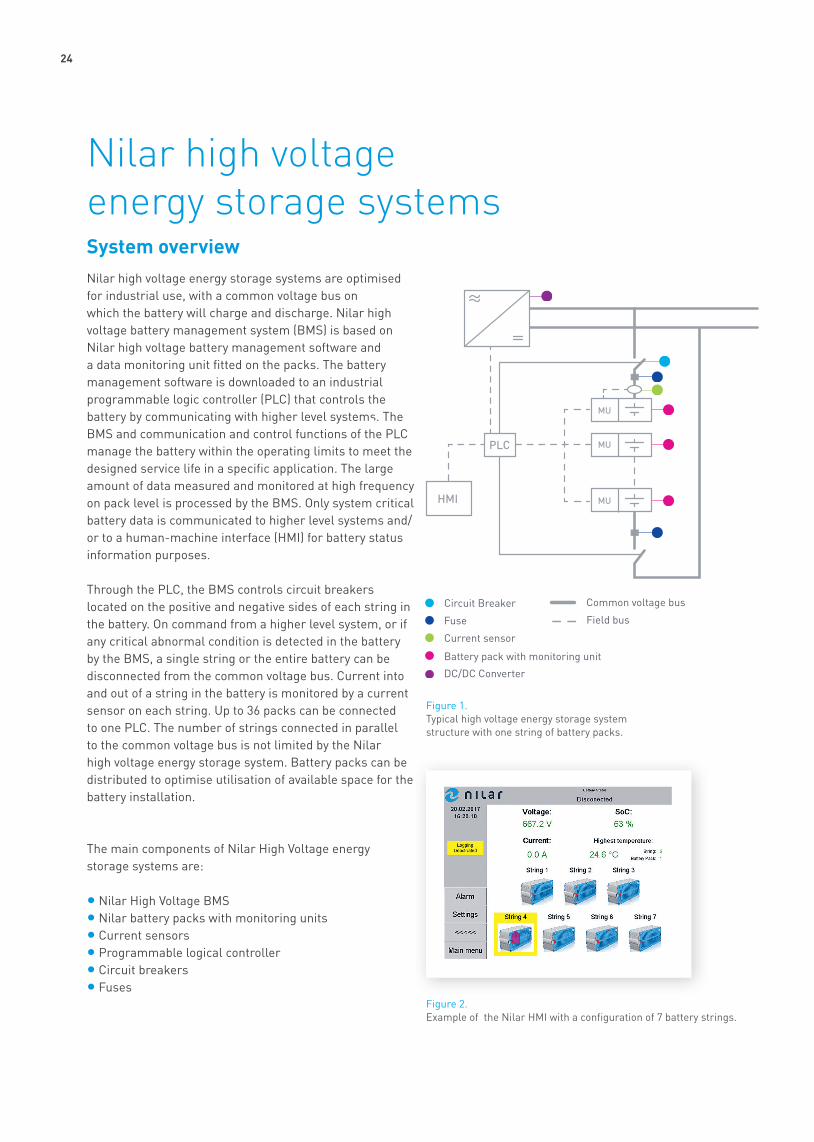
System overviewNilar high voltage energy storage systems are optimised for industrial use, with a common voltage bus on which the battery will charge and discharge. Nilar high voltage battery management system (BMS) is based on Nilar high voltage battery management software and a data monitoring unit fitted on the packs. The battery management software is downloaded to an industrial programmable logic controller (PLC) that controls the battery by communicating with higher level systems. The BMS and communication and control functions of the PLC manage the battery within the operating limits to meet the designed service life in a specific application. The large amount of data measured and monitored at high frequency on pack level is processed by the BMS. Only system critical battery data is communicated to higher level systems and/or to a human-machine interface (HMI) for battery status information purposes.
Through the PLC, the BMS controls circuit breakers located on the positive and negative sides of each string in the battery. On command from a higher level system, or if any critical abnormal condition is detected in the battery by the BMS, a single string or the entire battery can be disconnected from the common voltage bus. Current into and out of a string in the battery is monitored by a current sensor on each string. Up to 36 packs can be connected to one PLC. The number of strings connected in parallel to the common voltage bus is not limited by the Nilar high voltage energy storage system. Battery packs can be distributed to optimise utilisation of available space for the battery installation.
The main components of Nilar High Voltage energy storage systems are:
• Nilar High Voltage BMS• Nilar battery packs with monitoring units• Current sensors• Programmable logical controller• Circuit breakers• Fuses
Nilar high voltage energy storage systems
Figure 1. Typical high voltage energy storage system structure with one string of battery packs.
Figure 2. Example of the Nilar HMI with a configuration of 7 battery strings.
HMI
PLC
MU
MU
MU
Battery pack with monitoring unit

25
Condition Default limit BMS signal BMS action
Pack warm 40°C Warning No active action
Pack overheat 55°C Alarm Disconnect string
Pack pressure high 60 PSI Warning No active action
Pack over pressure 75 PSI Alarm Disconnect string
Pack pressure rise ±10 PSI/min Alarm Disconnect string
Pack pressure drop -10 PSI/10 s Alarm Disconnect string
Pack temperature low -10°C Warning No active action
Low voltage 11.5 V / module (10 cells) Warning No active action
High voltage 15.5 V / module (10 cells) Warning No active action
Low voltage 11 V / module (10 cells) Alarm Disconnect string
High voltage 16 V / module (10 cells) Alarm Disconnect string
Low state of charge 25 % Warning No active action
Low state of charge 20 % Warning Disconnect string
Low state of health 60 % Warning No active action
High ambient temperature 40°C Warning No active action
Low ambient temperature -10°C Warning No active action
Nilar High Voltage BMSNilar high voltage BMS is based on specific characteristics of Nilar battery packs and is developed to optimise utilisation of installed battery capacity and service life. The BMS will issue warnings or alarms to higher level systems when battery conditions are out of range. If critical conditions are detected in a string, the BMS will disconnect the string. The settings are optimised by Nilar depending on the system and application.
Through the PLC, Nilar high voltage BMS will issue commands to higher level systems to regulate charging. Charging is based on constant current charging with charge termination dependent on individual pack conditions. Charging to full capacity is performed with currents from 2 to 3 A per string. Full recharge from deep discharge is performed in less than 3.5 hours.
The battery can be cycled at an intermediate state of charge, with fast charge capability enabling short recharges where possible. Nilar high voltage BMS supports fast charging with a current up to 30 A per string.
10 minutes fast charge corresponds to 50 % of the rated battery capacity, providing sufficient power is available. Fast charging is enabled from 20 % state of charge and is terminated when 80 % state of charge is reached.
Figure 3. State of charge (SOC) window for fast charging.
HMI
PLC
LMU
LMU
LMU
Circuit Breaker
Fuse
Current sensor
LMU-pack
DC/DC Converter
Common voltage bus
Field bus
Low
High
Information
Application/HMI
PLC
LMU-packs
I+
I
SOC [%] 0 20 80 100
Fast charge

26
Configuration
In a common voltage bus system, with a fixed voltage window, the battery capacity required to meet the designed run time of the battery is determined by the number of strings connected in parallel on the common voltage bus. Each string increases the battery rated capacity by 10 Ah. The rated battery energy equals the rated pack energy in Wh multiplied by the number of packs in the battery.
Battery size is determined by a number of application-specific features such as voltage window, load profile, required run time and recharge opportunities. System design should also be considered. For instance, a system supported by photovoltaic arrays will require a different battery size than a hybridised system powered by a combustion engine and a battery. Charging infrastructure is also important: the number of charging stations or frequency of short recharging together with installed charger power will impact the optimum battery size.
Nominal string voltage [V] Battery pack Nominal pack voltage [V] Number of packs in series per string
60 HV 60V 10Ah 60 172 HV 72V 10Ah 72 184 HV 84V 10Ah 84 196 HV 96V 10Ah 96 1108 HV 108V 10Ah 108 1120 HV 120V 10Ah 120 1144 HV 72V 10Ah 72 2168 HV 84V 10Ah 84 2180 HV 60V 10Ah 60 3192 HV 96V 10Ah 96 2216 HV 108V 10Ah 108 2240 HV 120V 10Ah 120 2252 HV 84V 10Ah 84 3288 HV 96V 10Ah 96 3300 HV 60V 10Ah 60 5324 HV 108V 10Ah 108 3336 HV 84V 10Ah 84 4360 HV 120V 10Ah 120 3384 HV 96V 10Ah 96 4420 HV 84V 10Ah 84 5432 HV 108V 10Ah 108 4480 HV 120V 10Ah 120 4540 HV 108V 10Ah 108 5576 HV 96V 10Ah 96 6588 HV 84V 10Ah 84 7600 HV 120V 10Ah 120 5648 HV 108V 10Ah 108 6672 HV 96V 10Ah 96 7
720 HV 120V 10Ah 120 6
Table 1. Nominal string voltage as a function of pack size and number of packs in series.

27
Installation
A typical battery installation is shown in Figure 4. Battery packs are installed by laying on one of the long sides with the monitoring unit facing outwards for easy access during installation. Battery packs are secured to the support structure with screws and brackets.
The footprint of a typical 600 VDC installation with an installed energy of 48 kWh is shown in Figure 6. Strings are installed horizontally with 5 battery packs, of type HV 120V 10Ah, connected in series in each string. 8 strings connected in parallel on the common voltage bus equals a rated battery capacity of 80 Ah, corresponding to 48 kWh. Dimensions in Figure 6 are based on a battery pack type HV 120V 10Ah.
Figure 4. Typical battery installation.
Figure 5. Cabinet with installed PLC, circuit breakers and fuses.
Figure 6. Typical dimensions of a 600 VDC installation with an installed energy of 48 kWh.
28
Nilar system components
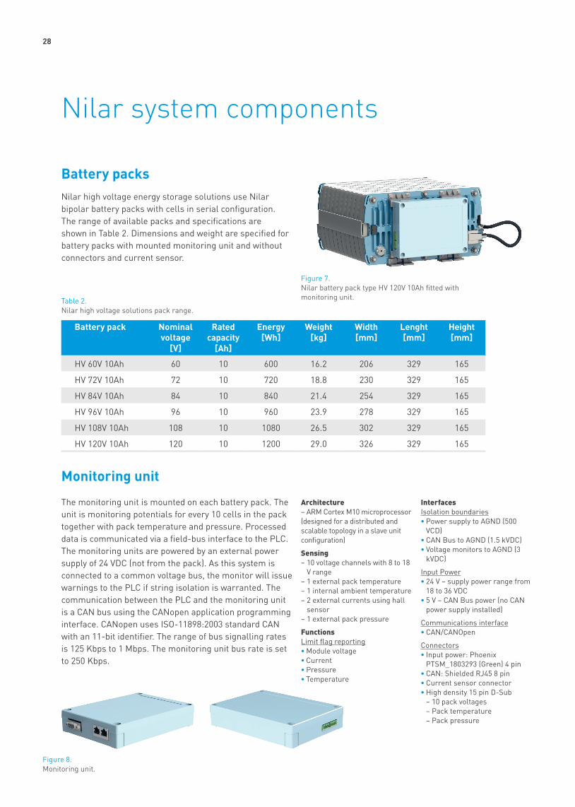
Battery packsNilar high voltage energy storage solutions use Nilar bipolar battery packs with cells in serial configuration. The range of available packs and specifications are shown in Table 2. Dimensions and weight are specified for battery packs with mounted monitoring unit and without connectors and current sensor.
Monitoring unit
The monitoring unit is mounted on each battery pack. The unit is monitoring potentials for every 10 cells in the pack together with pack temperature and pressure. Processed data is communicated via a field-bus interface to the PLC. The monitoring units are powered by an external power supply of 24 VDC (not from the pack). As this system is connected to a common voltage bus, the monitor will issue warnings to the PLC if string isolation is warranted. The communication between the PLC and the monitoring unit is a CAN bus using the CANopen application programming interface. CANopen uses ISO-11898:2003 standard CAN with an 11-bit identifier. The range of bus signalling rates is 125 Kbps to 1 Mbps. The monitoring unit bus rate is set to 250 Kbps.
Architecture – ARM Cortex M10 microprocessor (designed for a distributed and scalable topology in a slave unit configuration)
Sensing– 10 voltage channels with 8 to 18
V range– 1 external pack temperature– 1 internal ambient temperature– 2 external currents using hall
sensor– 1 external pack pressure
FunctionsLimit flag reporting• Module voltage• Current• Pressure• Temperature
InterfacesIsolation boundaries• Power supply to AGND (500
VCD)• CAN Bus to AGND (1.5 kVDC)• Voltage monitors to AGND (3
kVDC)
Input Power• 24 V – supply power range from
18 to 36 VDC• 5 V – CAN Bus power (no CAN
power supply installed)
Communications interface• CAN/CANOpen
Connectors• Input power: Phoenix
PTSM_1803293 (Green) 4 pin• CAN: Shielded RJ45 8 pin• Current sensor connector• High density 15 pin D-Sub
– 10 pack voltages – Pack temperature – Pack pressure
Figure 7. Nilar battery pack type HV 120V 10Ah fitted with monitoring unit.
Battery pack Nominal voltage
[V]
Rated capacity
[Ah]
Energy [Wh]
Weight [kg]
Width [mm]
Lenght [mm]
Height [mm]
HV 60V 10Ah 60 10 600 16.2 206 329 165
HV 72V 10Ah 72 10 720 18.8 230 329 165
HV 84V 10Ah 84 10 840 21.4 254 329 165
HV 96V 10Ah 96 10 960 23.9 278 329 165
HV 108V 10Ah 108 10 1080 26.5 302 329 165
HV 120V 10Ah 120 10 1200 29.0 326 329 165
Figure 8. Monitoring unit.
Table 2. Nilar high voltage solutions pack range.

29
Programmable logical controller (PLC)Nilar uses an Eaton PLC type XC200 as a master node for the distributed monitoring units. Other types of PLC are available on request. The PLC is programmed with Nilar high voltage BMS software for management of the battery and interaction with higher level systems. Up to 36 monitoring units can be connected to one PLC. The XC200 series modular PLCs are of scalable design and support integration in modern communication systems. This allows for energy storage systems with more than 36 battery packs by use of additional PLCs.
Circuit breakerTwo circuit breakers per string are required to enable disconnection of the string from the common voltage bus. The circuit breakers are hardwired to and controlled by the PLC. Circuit breakers can be provided on request.
FuseTwo fuses per string are recommended, one on the negative and one on the positive side and located close to the string. Fuses can be provided on request.
Current sensorThe current sensor provided by Nilar is an automotive grade current transducer of type DHAB S/44 produced by LEM. It has galvanic isolation between the primary circuit (high power) and the secondary circuit (electronic circuit). The open loop transducers use a Hall-effect integrated circuit. There is one current sensor per string, mounted on the battery pack on the negative side of the string.
Figure 9. Eaton XC200 PLC.
Figure 10. Battery pack with mounted current sensor.
Figure 11. Location of current sensor.
Figure 12. Current sensor.
• On board 14 I/O points • Locally expandable with up to
15 XIOC modules• On board RS-232 serial
interface• On board CANopen interface• On board Ethernet
• Integrated web server• On board high speed counter
inputs• On board encoder inputs• Ethernet, CANopen, PROFIBUS
DP, easyNet and Suconet K communications
• Good accuracy for high and low current range
• Good linearity• Low thermal offset drift• Low thermal sensitivity drift• Hermetic package• Low voltage application
• Unipolar + 5 V DC power supply• Primary current measuring
range up to ± 20 A • Operating temperature range: -
40 to + 125 °C• 2 measuring ranges for
increased accuracy.
Current sensor
I+
I

30
Nilar low voltage battery systemsNilar low voltage battery systems are based on the specific characteristics of Nilar low voltage battery packs. They are developed for optimal utilization of the battery capacity and service life. Nilar offers low voltage battery systems with nominal voltages from 12 to 48 V.
31
Features
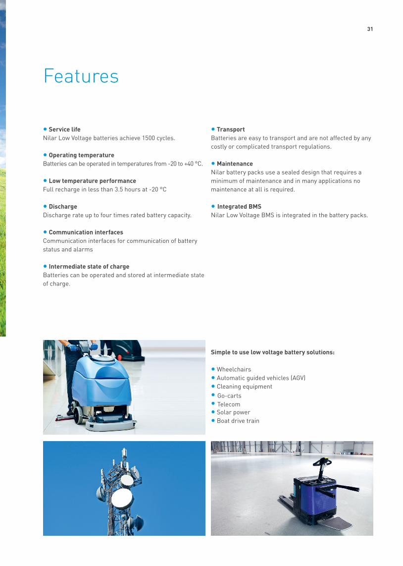
• Service lifeNilar Low Voltage batteries achieve 1500 cycles.
• Operating temperatureBatteries can be operated in temperatures from -20 to +40 °C.
• Low temperature performanceFull recharge in less than 3.5 hours at -20 °C
• DischargeDischarge rate up to four times rated battery capacity.
• Communication interfacesCommunication interfaces for communication of battery status and alarms
• Intermediate state of chargeBatteries can be operated and stored at intermediate state of charge.
• Transport Batteries are easy to transport and are not affected by any costly or complicated transport regulations.
• Maintenance Nilar battery packs use a sealed design that requires a minimum of maintenance and in many applications no maintenance at all is required.
• Integrated BMSNilar Low Voltage BMS is integrated in the battery packs.
Simple to use low voltage battery solutions:
• Wheelchairs• Automatic guided vehicles (AGV)• Cleaning equipment• Go-carts• Telecom• Solar power• Boat drive train
32
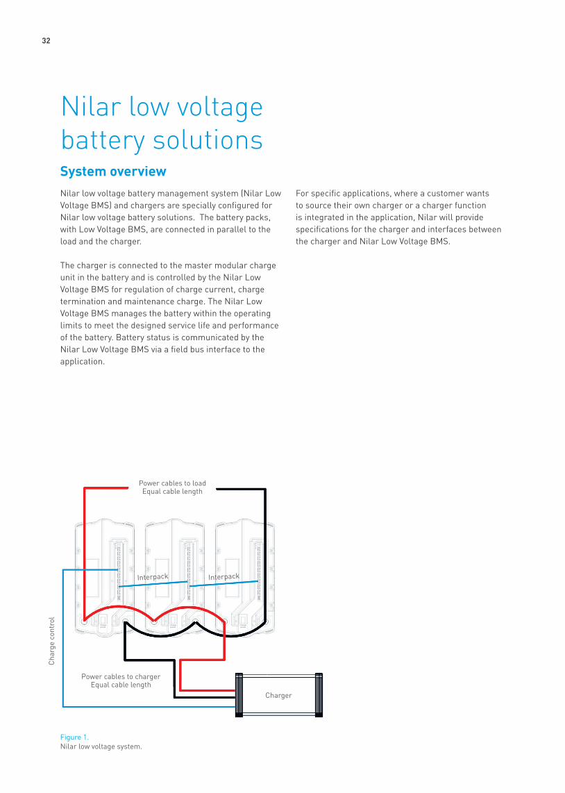
System overviewNilar low voltage battery management system (Nilar Low Voltage BMS) and chargers are specially configured for Nilar low voltage battery solutions. The battery packs, with Low Voltage BMS, are connected in parallel to the load and the charger.
The charger is connected to the master modular charge unit in the battery and is controlled by the Nilar Low Voltage BMS for regulation of charge current, charge termination and maintenance charge. The Nilar Low Voltage BMS manages the battery within the operating limits to meet the designed service life and performance of the battery. Battery status is communicated by the Nilar Low Voltage BMS via a field bus interface to the application.
For specific applications, where a customer wants to source their own charger or a charger function is integrated in the application, Nilar will provide specifications for the charger and interfaces between the charger and Nilar Low Voltage BMS.
Nilar low voltage battery solutions
Figure 1. Nilar low voltage system.
Power cables to loadEqual cable length
Cha
rge
cont
rol
Interpack Interpack
Charger
Power cables to chargerEqual cable length
33
Nilar Low Voltage Battery Management SystemNilar Low Voltage Battery Management System (BMS) is based on specific characteristics of Nilar low voltage battery packs and is developed to optimize utilization of installed battery capacity and service life. The Nilar Low Voltage BMS monitors the condition of the battery and communicates the battery condition and alarms, via a field bus. The Nilar Low Voltage BMS manage charging and discharging of the battery to keep the battery within the optimum operation limits and to maintain the battery capacity balance. Charge and discharge is disabled by the Nilar Low Voltage BMS if the battery condition is out of operating limits and if any critical condition is detected in the battery pack.
Nilar Low Voltage BMS supports discharge rates up to four times the rated battery capacity. The BMS disconnects the battery when fully discharged to prevent deep discharge. Charging is based on constant current charging with charge termination dependent on individual string conditions within the battery packs. After the battery packs are fully charged the Nilar Low Voltage BMS maintains the state of charge by a pulsed maintenance charge. This keeps the state of charge in the range of 90 to 100 %.
The Nilar Low Voltage BMS automatically goes into sleep mode if the charger is disconnected and the battery is not discharged for a period of time. The Nilar Low Voltage BMS wakes up if discharged or the charger is reconnected. Sleep mode can also be activated by the on/off switch. With the on/off switch in off mode the Nilar Low Voltage BMS is protected against external short circuit. When in operation the Nilar Low Voltage BMS protects the modular charge unit from harmful power loads and external short circuit by disconnecting the battery.
Battery status and alarms are communicated by the CANOpen and Modbus RTU application programming interfaces. The information communicated by the default settings are:
• Mode – Charging – Maintenance charge – Discharging – Idle – Fault
• Battery status – State of charge – Battery terminal current – Battery terminal voltage
• Warnings

34
Configuration
Battery packs with the same rated battery pack capacity and nominal voltage can be connected in parallel to achieve the required battery capacity. The range of battery configurations are shown in Table 1. Multiple battery packs can be connected in parallel. Battery packs can not be connected in series.
Nominal voltage [V] Battery capacity [Ah] [Wh]
Battery pack Number of packs connected in parallel
24 10 240 LV 24V 10Ah 1
24 20 480 LV 24V 20Ah 124 30 720 LV 24V 30Ah 124 40 960 LV 24V 40Ah 124 50 1200 LV 24V 50Ah 124 60 1440 LV 24V 60Ah 124 80 1920 LV 24V 40Ah 224 100 2400 LV 24V 50Ah 224 120 2880 LV 24V 60Ah 224 150 3600 LV 24V 50Ah 324 180 4320 LV 24V 60Ah 348 10 480 LV 48V 10Ah 148 20 960 LV 48V 20Ah 148 30 1440 LV 48V 30Ah 148 40 1920 LV 48V 20Ah 248 60 2880 LV 48V 30Ah 248 90 4320 LV 48V 30Ah 3
Table 1. Range of battery configurations.
35
Installation
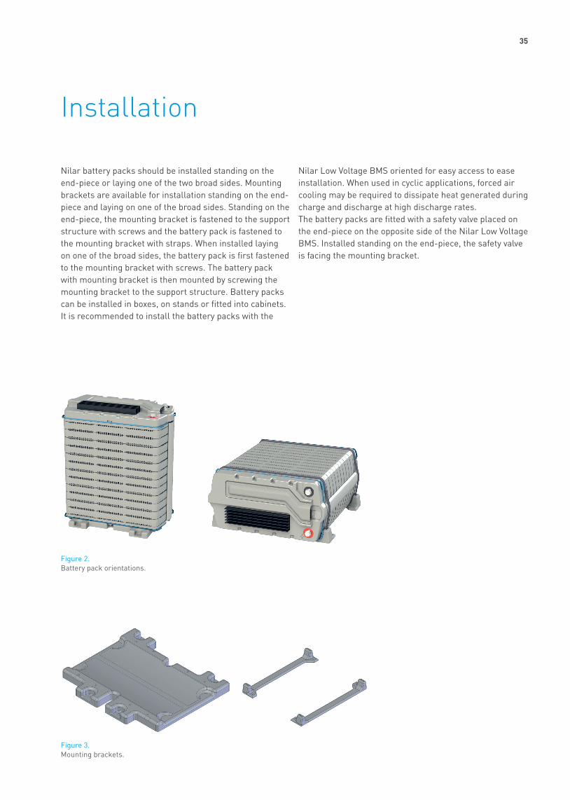
Nilar battery packs should be installed standing on the end-piece or laying one of the two broad sides. Mounting brackets are available for installation standing on the end-piece and laying on one of the broad sides. Standing on the end-piece, the mounting bracket is fastened to the support structure with screws and the battery pack is fastened to the mounting bracket with straps. When installed laying on one of the broad sides, the battery pack is first fastened to the mounting bracket with screws. The battery pack with mounting bracket is then mounted by screwing the mounting bracket to the support structure. Battery packs can be installed in boxes, on stands or fitted into cabinets. It is recommended to install the battery packs with the
Nilar Low Voltage BMS oriented for easy access to ease installation. When used in cyclic applications, forced air cooling may be required to dissipate heat generated during charge and discharge at high discharge rates. The battery packs are fitted with a safety valve placed on the end-piece on the opposite side of the Nilar Low Voltage BMS. Installed standing on the end-piece, the safety valve is facing the mounting bracket.
Figure 3. Mounting brackets.
Figure 2. Battery pack orientations.

36
Figure 4. Safety valve.
Safety valveThe battery packs are connected in parallel to the charger through the junction box as shown in Figure 5. The Low Voltage BMS units in a multi pack installation communicates with each other by the inter-pack communication cables. The inter pack communication cables are connected to the Low Voltage BMS in a daisy chain by connecting to interface 3 and 4. The master BMS is connected to the charger by the charger control cable. Battery packs are connected in parallel by connecting the negative battery pack terminals on the Low Voltage BMS units with cables and connecting the positive battery pack terminals on the Low Voltage BMS with cables. The load is connected to the battery by connecting the load to the positive- and negative- battery pack terminals on one of the battery packs. It is recommended to have the on/off switch on the Low Voltage BMS in the off position during installation and turn them on after the installation is competed. Up to eight battery packs can be connected to one charger.
Figure 5. Electrical installation.
Charger
Charger control cable
Battery pack
Junction box
Inter-pack communication cable
Charge power cable

37
Battery pack range
Nilar offers the following range of battery packs with the Low Voltage BMS. Dimensions and weight are specified for battery packs with Low Voltage BMS unit excluding cables and connectors.
Table 2. Battery pack dimensions.
Figure 6. Dimensions.Width
Hei
ght
Length
Nilar battery pack Nominal Voltage
Rated pack capacity
Max discharge rate
Dimensions Weight
Width Length HeightV Ah A mm mm mm kg
LV 24 V 10Ah 24 10 20 165 329 116 9.30LV 24 V 20Ah 24 20 40 165 329 165 14.48LV 24 V 30Ah 24 30 60 165 329 214 19.70LV 24 V 40Ah 24 40 80 165 329 263 24.85LV 24 V 50Ah 24 50 100 165 329 312 30.04LV 24 V 60Ah 24 60 120 165 329 361 35.22LV 48 V 10Ah 48 10 10 165 329 164 14.50LV 48 V 20Ah 48 20 20 165 329 261 24.87LV 48 V 30Ah 48 30 30 165 329 358 35.25LV-H 24 V 10Ah 24 10 40 165 329 116 9.55LV-H 24 V 20Ah 24 20 80 165 329 165 14.73LV-H 24 V 30Ah 24 30 120 165 329 214 19.95LV-H 24 V 40Ah 24 40 160 165 329 263 25.10LV-H 24 V 50Ah 24 50 200 165 329 312 30.29LV-H 24 V 60Ah 24 60 240 165 329 361 35.50LV-H 48 V 10Ah 48 10 20 165 329 164 14.75LV-H 48 V 20Ah 48 20 40 165 329 261 25.12LV-H 48 V 30Ah 48 30 60 165 329 358 35.50

38
There are two versions of the Low Voltage BMS, standard and high discharge rate. The high discharge rate version is fitted with a heat sink to dissipate heat generated in the electronics when discharging with high discharge rates.
The Low Voltage BMS is an electronic control system for Nilar low voltage battery packs. The Low Voltage BMS is factory mounted on the battery pack. Cells are connected in series in to strings to achieve the nominal voltage of the battery pack and the strings are connected in parallel in the battery pack to achieve the rated capacity. The Low Voltage BMS measures voltage, temperature and current on string level and battery pack pressure. These signals provide reference for battery management algorithms and diagnostic information regarding battery condition. The Low Voltage BMS has six channels for control of up to six battery strings per battery pack. The design allows the Nilar Low Voltage BMS to disconnect individual strings or the entire battery pack on charging and discharging. The Low Voltage BMS is powered from the battery. The Low Voltage BMS is fitted with electronic fuses protecting the electronic circuits from external short circuit. With the on/off switch in off position the battery pack terminals on the Low Voltage BMS is disconnected from battery power and the electronics is put on sleep mode to minimize parasitic load on the battery.
Low Voltage BMS
Figure 7. Low Voltage BMS unit. Standard and high discharge rate.

39
Figure 8. Description of modular charge unit.
Architecture• ARM Cortex M10 microprocessor designed for a
distributed and scalable topology in a master slave unit configuration
Sensing• 6 battery string voltage channels• 6 battery string temperature channels• 6 battery string current channels• 1 battery pack pressure channel• 1 internal ambient temperature channel• 1 battery pack voltage channel
InterfacesInput power• Powered by battery pack
Charger control• 0 – 5 V analog output• +5 V from charger
Communication interfaces• Modbus RTU• CAN Open• Inter-pack communication• Digital in• Digital out
Charge power• Plus and minus from charger
Battery pack terminals• Positive- and negative battery pack terminals• M8 x 13 mm
Service• Nilar service interface
On/off switch
Positive battery pack terminal
CANRS485RS232
Negative battery pack terminal
On/Off switch
Current sensor
Voltage sensor
Pressure sensor
Temperature sensor
Charge control+ 5 VDC0–5 VDCGround
MOSFET’s
Fuse 40 A
Battery pack string
I
U
P
T
I
U
P
T
Controller
Positive battery pack terminal
CANRS485RS232
Negative battery pack terminal
On/Off switch
Current sensor
Voltage sensor
Pressure sensor
Temperature sensor
Charge control+ 5 VDC0–5 VDCGround
MOSFET’s
Fuse 40 A
Battery pack string
I
U
P
T
I
U
P
T
Controller
Positive battery pack terminal
CANRS485RS232
Negative battery pack terminal
On/Off switch
Current sensor
Voltage sensor
Pressure sensor
Temperature sensor
Charge control+ 5 VDC0–5 VDCGround
MOSFET’s
Fuse 40 A
Battery pack string
I
U
P
T
I
U
P
T
Controller

40
On/Off switch
Negative battery pack terminal M8 x 13 mm
Interface connectors
Charge power connector
Positive battery pack terminal M8 x 13 mm
Interface connectors
Figure 9. Interface connectors.
Interface Connector
1 CAN in Molex Mini-Lock 53375-0410, 4 pin
2 CAN out Molex Mini-Lock 53375-0410, 4 pin
3 Inter-pack communication connector in, for communication between battery packs connected in parallel
4 Inter-pack communication connector out, for communication between battery packs connected in parallel
5 Modbus RTU (RS485) Molex Mini-Lock 53375-0410, 4 pin
6 Charger control Molex Mini-Lock 53375-0310, 3 pin
7 Digital in x 2 Molex Mini-Lock 53375-0310, 3 pin2 digital input
8 Digital out x 2 Molex Mini-Lock 53375-0410, 4 pin2 relay out puts, 1 A 60 VDC
9 Nilar service connector
10 RS232 Molex Mini-Lock 53375-0310, 3 pin
11 Charge power Hirose DF60-2P-10.16DS, 2 pinPositive and negative power cables from charger
Table 3. Interface connectors. Number 1 located closest to the charge power connector.

41
Table 4. Charger selection table.
The chargers provided by Nilar are from Primepower and have been adapted to suite Nilar low voltage battery systems. The chargers are controlled by Nilar Low Voltage BMS for regulation of charge current. The chargers are delivered with charge cables and a signal cable for communication with Nilar Low Voltage BMS. The signal cable is connected to the master modular charge unit in the battery. The type of charger to be used for a specific battery capacity is shown in Table 4. Charger specifications are shown in Table 5.
For specific applications, where a customer wants to source their own charger or a charger function is integrated in the application, Nilar will provide specifications for the charger and interfaces between the charger and Nilar Low Voltage BMS.
Nominal voltage [V] Battery capacity [Ah] Charger LV Charger
24 10 240 LV Charger 24V 800W24 20 480 LV Charger 24V 800W24 30 720 LV Charger 24V 800W24 40 960 LV Charger 24V 800W24 50 1200 LV Charger 24V 800W24 60 1440 LV Charger 24V 800W24 80 1920 LV Charger 24V 1600W24 100 2400 LV Charger 24V 1600W24 120 2880 LV Charger 24V 1600W24 150 3600 LV Charger 24V 3200W24 160 3840 LV Charger 24V 3200W24 180 4320 LV Charger 24V 3200W24 200 4800 LV Charger 24V 3200W24 240 5760 LV Charger 24V 3200W24 300 7200 LV Charger 24V 3200W48 10 480 LV Charger 24V 3200W48 20 960 LV Charger 48V 800W48 30 1440 LV Charger 48V 800W48 40 1920 LV Charger 48V 800W48 60 2880 LV Charger 48V 1600W48 90 4320 LV Charger 48V 1600W48 120 5760 LV Charger 48V 3200W48 150 7200 LV Charger 48V 3200W48 180 8640 LV Charger 48V 3200W48 210 10080 LV Charger 48V 3200W48 240 11520 LV Charger 48V 3200W
41
Figure 10. Nilar charger.
Chargers

42
LV Charger 24V 800W LV Charger 24V 1600W LV Charger 24V 3200WLV Charger 48V 800W LV Charger 48V 1600W LV Charger 48V 3200W
Input Voltage 200-250 VAC, 50 Hz 200-250 VAC, 50 Hz 230-264 VAC, 50 Hz
Maximum current consumption from mains 4.5 A 9 A 16 A
Maximum charge voltage 36 V / 72 V 36 V / 72 V 36 V / 72 VMaximum charge current 20 A / 15 A 20 A /30 A 20 A / 68 AMaximum charge power 800 W 1600 W 3200 WBattery charge cable RK Twin 2 x 6 mm2 RK Twin 2 x 10 mm2 RK Twin 2 x 50 mm22
Battery charge cable length 2 m 2 m 2 mModular charge unit cable length 1.5 m 1.5 m 1.5 m
Modular charge unit cable connector RJ-connector RJ-connector RJ-connector
Power cable AC 1.5 m 1.5 m 1.5 mIngress protection class IP20 IP20 IP20
Electrical safety standard EN 60950-1:2001 EN 60950 EN60 335-2-29
EN 60950-1EN 60335-2-29
EN 60335-1EN50366
EMC standard EN 55022BEN 55022BEN50081-1EN50082-2
EN 55022B
Approvals CE CE 93/68/EECReversed polarity protection Yes Yes YesShort circuit protection Yes Yes YesOperating temperature range -25 °C to +50 °C -25 °C to +50 °C -25 °C to +50 °CStorage temperature range -55 °C to + 85 °C -55 °C to +85 °C -55 °C to +85 °CDimensions (H x L x W) 73 x 220 x 112 mm 85 x 267 x 135 mm 250 x 400 x 80 mmWeight 1.55 kg 1.9 kg 7.1 kg
Table 5. Charger specifications.

43
Notes

Nilar Doc. No.: 73-F003-R02www.nilar.com
Nilar AB Headquarters and Sales
Stockholmsvägen 116 B SE-187 30 Täby Sweden Phone: +46 (0)8 768 00 00 Email: [email protected]
Nilar AB R&D and Production
Bönavägen 55 Box 8020 SE-800 08 Gävle Sweden Phone: +46 (0)26 960 90 Email: [email protected]
Nilar Inc. Sales USA
Suite 525, 10800 E. Bethany Drive Aurora, CO 80014 USA Phone: +1 720 446 0169 Email: [email protected]