technical iso/tr report 12748 - iteh standards store
TRANSCRIPT
© ISO 2015
Natural Gas — Wet gas flow measurement in natural gas operationsGaz naturel — Mesurage du débit de gaz humide dans les opérations de gaz naturel
TECHNICAL REPORT
ISO/TR12748
Reference numberISO/TR 12748:2015(E)
First edition2015-10-15
iTeh STANDARD PREVIEW(standards.iteh.ai)
ISO/TR 12748:2015https://standards.iteh.ai/catalog/standards/sist/91df86a9-d46d-4926-b341-
5117a600021c/iso-tr-12748-2015

ISO/TR 12748:2015(E)
ii © ISO 2015 – All rights reserved
COPYRIGHT PROTECTED DOCUMENT
© ISO 2015, Published in SwitzerlandAll rights reserved. Unless otherwise specified, no part of this publication may be reproduced or utilized otherwise in any form or by any means, electronic or mechanical, including photocopying, or posting on the internet or an intranet, without prior written permission. Permission can be requested from either ISO at the address below or ISO’s member body in the country of the requester.
ISO copyright officeCh. de Blandonnet 8 • CP 401CH-1214 Vernier, Geneva, SwitzerlandTel. +41 22 749 01 11Fax +41 22 749 09 [email protected]
iTeh STANDARD PREVIEW(standards.iteh.ai)
ISO/TR 12748:2015https://standards.iteh.ai/catalog/standards/sist/91df86a9-d46d-4926-b341-
5117a600021c/iso-tr-12748-2015
ISO/TR 12748:2015(E)
Foreword ........................................................................................................................................................................................................................................viIntroduction ..............................................................................................................................................................................................................................vii1 Scope ................................................................................................................................................................................................................................. 12 Terms and Definitions .................................................................................................................................................................................... 13 Symbols .......................................................................................................................................................................................................................104 Objectives of wet gas flow measurement .................................................................................................................................13
4.1 Common production scenarios .............................................................................................................................................. 144.2 Production allocation ..................................................................................................................................................................... 154.3 Flow assurance aspects ................................................................................................................................................................ 164.4 WGFM considerations .................................................................................................................................................................... 164.5 Reliability in remote WGFM installations ..................................................................................................................... 16
5 Flow regimes ..........................................................................................................................................................................................................175.1 Horizontal wet gas flow regimes .......................................................................................................................................... 17
5.1.1 Stratified flow .................................................................................................................................................................. 185.1.2 Slug flow ............................................................................................................................................................................... 185.1.3 Annular mist flow .........................................................................................................................................................18
5.2 Vertical up wet gas flow regimes .......................................................................................................................................... 185.2.1 Churn flow ..........................................................................................................................................................................185.2.2 Annular mist flow .........................................................................................................................................................19
5.3 Vertical down wet gas flow regimes .................................................................................................................................. 195.4 Inclined flow........................................................................................................................................................................................... 195.5 Examples of wet gas flow regimes ...................................................................................................................................... 195.6 Flow regime maps ............................................................................................................................................................................. 205.7 Different wet gas flow parameters...................................................................................................................................... 215.8 Water in wet gas flow ..................................................................................................................................................................... 21
6 Wet gas flow metering principles .....................................................................................................................................................226.1 General ........................................................................................................................................................................................................ 226.2 In-Line wet gas flow meters ..................................................................................................................................................... 23
6.2.1 Single-phase gas flow meter with correction factor ......................................................................236.2.2 Two-phase wet gas flow meter ......................................................................................................................... 246.2.3 Multiphase wet gas flow meter ........................................................................................................................ 24
6.3 Single-phase gas differential pressure meters with wet gas flow ............................................................246.3.1 DP Meter design influence on wet gas over-reading .....................................................................256.3.2 Lockhart-Martinelli parameter influence on DP meter wet gas
flow over-reading .........................................................................................................................................................256.3.3 Gas to liquid density ratio influence on DP meter wet gas flow over-reading ........256.3.4 Gas densiometric Froude number influence on DP meter wet gas
flow over-reading .........................................................................................................................................................266.3.5 DP meter orientation influence on DP meter wet gas flow over-reading ....................266.3.6 Influence of β on DP meter wet gas flow over-reading ................................................................286.3.7 Fluid property influence on DP meter wet gas flow over-reading.....................................286.3.8 Meter size/diameter influence on DP meter wet gas flow over-reading .....................286.3.9 Applying DP meter wet gas flow correlations .....................................................................................28
6.4 General discussion on DP meter wet gas correlations ......................................................................................296.4.1 Wet gas flow performance characterization vs. published wet gas correlations ..296.4.2 Horizontally-installed orifice plate meter ...............................................................................................296.4.3 Horizontally-installed Venturi meter ..........................................................................................................316.4.4 Horizontally-installed cone meter ................................................................................................................. 32
6.5 Generic two-phase wet gas meter designs ................................................................................................................... 336.5.1 Multiple single-phase meters in series ......................................................................................................336.5.2 Differential pressure meter classical DP/permanent pressure loss wet
gas meters ...........................................................................................................................................................................35
© ISO 2015 – All rights reserved iii
Contents Page
iTeh STANDARD PREVIEW(standards.iteh.ai)
ISO/TR 12748:2015https://standards.iteh.ai/catalog/standards/sist/91df86a9-d46d-4926-b341-
5117a600021c/iso-tr-12748-2015
ISO/TR 12748:2015(E)
6.5.3 Fast response sensor system .............................................................................................................................. 366.6 Multiphase wet gas flow meters ........................................................................................................................................... 37
6.6.1 Trace water metering with multiphase wet gas flow meters .................................................386.6.2 Multiphase wet gas flow meter subsystems .........................................................................................386.6.3 Phase fraction device choices ............................................................................................................................ 396.6.4 Gas volume fraction vs. gas void fraction measurement ............................................................416.6.5 Semi-empirical multiphase flow calculation — Slip model .....................................................416.6.6 PVT (pressure volume temperature) models ......................................................................................426.6.7 Multiphase wet gas flow meter required fluid property inputs ...........................................426.6.8 Multiphase wet gas flow meter phase fraction measurement ..............................................426.6.9 Measurement of water salinity ......................................................................................................................... 436.6.10 Multiphase wet gas flow meter redundant subsystems and diagnostics.....................436.6.11 Selection of multiphase wet gas flow meter technologies ........................................................44
6.7 Wet gas flow meter performance testing ...................................................................................................................... 446.8 Virtual metering system (VMS) ............................................................................................................................................. 45
7 DP Meter Wet Gas Correlation Practical Issues .................................................................................................................457.1 DP meter wet gas flow installation issues .................................................................................................................... 46
7.1.1 Liquid flow rate estimation techniques ....................................................................................................467.1.2 Monitoring wet gas liquid loading with a DP meter downstream port .........................47
8 Design and Installation Considerations ....................................................................................................................................498.1 Design considerations.................................................................................................................................................................... 49
8.1.1 Meter orientation and fluid flow .....................................................................................................................498.1.2 Meter location relative to other piping components .....................................................................508.1.3 Use of two-phase flow rate and composition maps ........................................................................508.1.4 Fluid sampling.................................................................................................................................................................528.1.5 Redundancy and external environmental considerations ........................................................528.1.6 Security ................................................................................................................................................................................. 538.1.7 Cost and project schedule implications ....................................................................................................54
8.2 Performance specifications ....................................................................................................................................................... 548.3 Wet gas flow measurement uncertainty ........................................................................................................................ 55
8.3.1 Uncertainty evaluation methodologies .....................................................................................................558.3.2 Additional factors affecting wet gas flow measurement uncertainty .............................558.3.3 Expressing uncertainty of wet gas flow rates ......................................................................................56
9 Testing, Verification and Calibration ............................................................................................................................................569.1 Meter orientation ............................................................................................................................................................................... 569.2 Comments on flow regimes and mixers ......................................................................................................................... 579.3 Installation requirements ........................................................................................................................................................... 579.4 Wet gas flow characterization tests — Single-phase DP meter baselines ........................................579.5 Wet gas flow facility operational considerations ...................................................................................................58
9.5.1 Test facility operational issues — Achieving thermodynamic equilibrium ...............589.5.2 Test facility operational issues — Phase flow rate stability ....................................................609.5.3 Test facility operational issues — Witnessing of tests .................................................................61
9.6 Meter testing in a wet gas flow facility ............................................................................................................................ 6210 Operational and Field Verification Issues ...............................................................................................................................65
10.1 Laboratory reference vs. field hydrocarbon flow composition estimates ........................................6610.2 Laboratory reference vs. field calibration of phase fractions ......................................................................6610.3 Comparisons of multiphase wet gas flow meter and single-phase meter requirements ....66
10.3.1 The challenge of supplying multiphase wet gas flow fluid properties ...........................6610.3.2 Confidential slip models ......................................................................................................................................... 67
10.4 The importance of correct fluid property predictions ......................................................................................6710.4.1 The importance of gas properties when metering small liquid flow rates ................7010.4.2 Preparation for fluid property variations during meter service .........................................7110.4.3 Fluid property sensitivity investigation....................................................................................................71
10.5 The benefit of an initial wet gas flow facility test ...................................................................................................7310.6 Line size limitations for some multiphase meters ................................................................................................7310.7 In situ wet gas flow meter verification ........................................................................................................................... 73
iv © ISO 2015 – All rights reserved
iTeh STANDARD PREVIEW(standards.iteh.ai)
ISO/TR 12748:2015https://standards.iteh.ai/catalog/standards/sist/91df86a9-d46d-4926-b341-
5117a600021c/iso-tr-12748-2015
ISO/TR 12748:2015(E)
10.7.1 Reconciliation factors and meter output confidence ....................................................................7410.8 Operation and maintenance ..................................................................................................................................................... 74
10.8.1 System redundancy and diagnostics ...........................................................................................................7410.8.2 Operating WGFM diagnostics ............................................................................................................................ 75
10.9 Miscellaneous operational issues ........................................................................................................................................ 7610.9.1 Wet gas flow and DP transmitters ................................................................................................................. 7610.9.2 Software and fluid property update procedures ...............................................................................7710.9.3 Long term trending comparisons with test facility/factory characterization .........77
11 Common Field Issues ....................................................................................................................................................................................7711.1 Inefficient separator systems .................................................................................................................................................. 7711.2 Separator systems — An adverse environment for single-phase meters .........................................78
11.2.1 Separator Outlet deployment ............................................................................................................................ 7911.2.2 Gas Measurement at the separator outlet ...............................................................................................7911.2.3 Liquid Turbine Meter ................................................................................................................................................8011.2.4 Practical limitations of wet gas flow metering with separator technology ...............80
11.3 Wet gas flow meter practical problems .......................................................................................................................... 8111.3.1 Considerations for wet gas flow metering ..............................................................................................8111.3.2 The adverse effects of contamination, hydrates, scale, and salts ........................................8211.3.3 Theoretical, laboratory and actual wet gas flow conditions ...................................................8411.3.4 Undisclosed WGFM calculation procedures ..........................................................................................8411.3.5 Differential pressure measurement and wet gas flows ...............................................................8511.3.6 Problems due to lack of long time operating experience of WGFMs ...............................86
Annex A (informative) WGFM design checklist.......................................................................................................................................87Annex B (informative) Wet gas parameters equations ...................................................................................................................89Bibliography .............................................................................................................................................................................................................................90
© ISO 2015 – All rights reserved v
iTeh STANDARD PREVIEW(standards.iteh.ai)
ISO/TR 12748:2015https://standards.iteh.ai/catalog/standards/sist/91df86a9-d46d-4926-b341-
5117a600021c/iso-tr-12748-2015
ISO/TR 12748:2015(E)
Foreword
ISO (the International Organization for Standardization) is a worldwide federation of national standards bodies (ISO member bodies). The work of preparing International Standards is normally carried out through ISO technical committees. Each member body interested in a subject for which a technical committee has been established has the right to be represented on that committee. International organizations, governmental and non-governmental, in liaison with ISO, also take part in the work. ISO collaborates closely with the International Electrotechnical Commission (IEC) on all matters of electrotechnical standardization.
The procedures used to develop this document and those intended for its further maintenance are described in the ISO/IEC Directives, Part 1. In particular the different approval criteria needed for the different types of ISO documents should be noted. This document was drafted in accordance with the editorial rules of the ISO/IEC Directives, Part 2 (see www.iso.org/directives).
Attention is drawn to the possibility that some of the elements of this document may be the subject of patent rights. ISO shall not be held responsible for identifying any or all such patent rights. Details of any patent rights identified during the development of the document will be in the Introduction and/or on the ISO list of patent declarations received (see www.iso.org/patents).
Any trade name used in this document is information given for the convenience of users and does not constitute an endorsement.
For an explanation on the meaning of ISO specific terms and expressions related to conformity assessment, as well as information about ISO’s adherence to the WTO principles in the Technical Barriers to Trade (TBT), see the following URL: Foreword — Supplementary information.
The committee responsible for this document is ISO/TC 193, Natural Gas, Subcommitte SC 3, Upstream Area.
vi © ISO 2015 – All rights reserved
iTeh STANDARD PREVIEW(standards.iteh.ai)
ISO/TR 12748:2015https://standards.iteh.ai/catalog/standards/sist/91df86a9-d46d-4926-b341-
5117a600021c/iso-tr-12748-2015

ISO/TR 12748:2015(E)
Introduction
Oil and gas companies started developing Wet Gas Flow Meters (WGFMs) and Multiphase Flow Meters (MPFMs) through extensive R&D activities in the late 1980s. During this period, WGFMs and MPFMs were typically perceived as two distinct technologies for different applications: MPFMs were designed for liquid continuous flow conditions and WGFMs were designed for gas continuous flow conditions. In recent years, however, the operating range of these two technologies has increasingly overlapped, blurring the distinction between a WGFM and MPFM. As wet gas flow is presently considered a subset of multiphase flow, a WGFM is an MPFM that specializes in gas-dominant multiphase flow conditions. In this Technical Report, such technologies will be referred to as WGFMs.
There are many factors that contributed in the decision to replace a separator with a WGFM, with each application warranting careful consideration. A well-designed and maintained separator working within an appropriate flow condition range should produce accurate flow measurements. A primary concern for oil and gas companies was to reduce costs by replacing complex and bulky test separators, as well as to further simplify the upstream infrastructure, in particular for offshore and subsea projects. WGFMs typically require lower capital1) and operational2) expenditures than fully equipped test separators. More savings in CapEx may be achieved by omitting dedicated test lines in satellite developments. In addition, there is a significant benefit for offshore developments, in terms of weight and space conservation, by using the much smaller footprint of WGFMs.
Due to various operational problems, a conventional test separator does not continuously provide accurate and reliable well test data, giving only relevant information when the well is switched to the test separator. With the use of WGFMs testing well production more frequently or even continuously becomes possible. WGFM developments and extensive testing over the last two decades have resulted in WGFM technology that is a viable alternative to a test separator. Modern WGFMs now offer continuous well monitoring (per installation on individual wells).
WGFM technology is an attractive option for multiphase wet gas flow measurement. Over the last two decades, some WGFMs have been developed from prototypes into very mature, robust, advanced, and field-proven measurement devices, increasing their application scope. Although originally intended for use mainly in reservoir and well production allocations, WGFMs have evolved into a technology that spans even fiscal product allocation. In the latter case, the output of a WGFM is used to determine money transactions between operating companies or between an operating company and a host government.
This Technical Report focuses on the measurement of wet gas flow, i.e. terminology, models, and principles, and the design, implementation, testing, and operation of WGFMs.
1) Capital expenditure (CapEx) or costs for purchasing and installing a WGFM/MPFM includes all hardware to operate the WGFM (data transmission, verification facilities, sampling arrangements, etc.)2) Operating expenditure (OpEx) or costs to operate a WGFM/MPFM (maintenance, verification processes, sampling for fluid properties, etc.)
© ISO 2015 – All rights reserved vii
iTeh STANDARD PREVIEW(standards.iteh.ai)
ISO/TR 12748:2015https://standards.iteh.ai/catalog/standards/sist/91df86a9-d46d-4926-b341-
5117a600021c/iso-tr-12748-2015

iTeh STANDARD PREVIEW(standards.iteh.ai)
ISO/TR 12748:2015https://standards.iteh.ai/catalog/standards/sist/91df86a9-d46d-4926-b341-
5117a600021c/iso-tr-12748-2015
Natural Gas — Wet gas flow measurement in natural gas operations
1 Scope
This Technical Report describes production flow measurement of wet natural gas streams with WGFMs in surface and subsea facilities. Wet natural gas streams are gas-dominated flows with liquids like water and/or hydrocarbon liquids3) (see 2.67 for a detailed definition). This Technical Report defines terms/symbols, explains the various concepts, and describes best practices of wet gas flow meter design and operation. It addresses metering techniques, testing, installation, commissioning, and operation practices such as maintenance, calibration, and verification. It also provides a theoretical background of this comprehensive, challenging and still evolving measurement technology.
There are four general methods in measuring wet natural gas flow. Each approach is detailed below.
— Single-phase gas flow meter with correction factor: Uses a single-phase gas flow meter (often a conventional gas flow metering device) with a correction factor for the effect of liquid on the metering system. In these cases, the liquid flow rate required to determine the correction factor, should be estimated from an external source.
— Two-phase WGFM: The gas and liquid (both water and hydrocarbon liquid combined) flow rates are predicted with no additional external information regarding the liquid flow rate required. This is generally known as a two-phase WGFM and will be referred to in this Technical Report simply as WGFM.
— WGFM: A flow meter that measures the gas and liquid flow rates, and also the gas, water and hydrocarbon liquid ratios (or “phase fractions”) with no external information required regarding the liquid flow rate.
— Phase separation/Measurement after phase separation: This traditional and conventional method of wet gas flow metering uses a two- or three-phase separator with single-phase flow meters measuring the outgoing single-phase flows.
The first three of these methods, which emerged in the last two decades, may be described as in-line wet gas flow metering, i.e. wet gas flow measurement is executed with WGFMs without separating the gas and liquid phases. This Technical Report discusses in detail these first three methods. Several best practice documents have already been issued to describe, among other topics, wet gas flow measurement[9][10][11][12].
The last method is more conventional and describes wet gas flow measurement after the gas and liquid phases have been separated. Wet gas meters can be used in multiphase flow metering systems that utilize partial separation technologies. This method is only briefly discussed in this Technical Report.
2 Terms and Definitions
For the purposes of this document, the following terms and definitions apply.
2.1adjustmentact of altering an instrument’s performance in any way, e.g. software, mechanical or electrical modifications, in order for the instrument’s indication to match the reference values indicated by a test stand
3) In this Technical Report, the term hydrocarbon liquid includes both oil and condensed hydrocarbons.
TECHNICAL REPORT ISO/TR 12748:2015(E)
© ISO 2015 – All rights reserved 1
iTeh STANDARD PREVIEW(standards.iteh.ai)
ISO/TR 12748:2015https://standards.iteh.ai/catalog/standards/sist/91df86a9-d46d-4926-b341-
5117a600021c/iso-tr-12748-2015
ISO/TR 12748:2015(E)
2.2calibrationset procedure under specified conditions where the output/performance of an instrument is checked against a reference, usually a test stand
Note 1 to entry: The result of calibration determines the deviation between the instrument indication and the references. This deviation can assign an uncertainty value to the measurand and could indicate a requirement for an adjustment.
2.3capacitancethe ability of a body to store an electrical charge
Note 1 to entry: Any object that can be electrically charged exhibits capacitance (e.g. a parallel-plate capacitor).
2.4composition mapmap with water liquid ratio or WLR (2.63) along the horizontal axis (0 % ≤ WLR ≤ 100 %) and gas volume fraction or GVF (2.22) along the vertical axis (0 % ≤ GVF ≤ 100 %); used to show WGFM operating envelopes and/or well trajectories (2.65)
Note 1 to entry: The combination of a two-phase flow rate map (2.59) and a composition map is beneficial to evaluate WGFM applications. See 8.1.3.
2.5conductivityability of a material to conduct electrical current
Note 1 to entry: In isotropic material, conductivity is also the reciprocal of resistivity, sometimes called specific conductance.
2.6density ratioDRratio of gas density to liquid density at line conditions, or
DR = ρ ρg l
Note 1 to entry: In multiphase wet gas flows, the liquid density is typically considered to be the density of a homogenous mix of liquid components. See Formula (6).
2.7dry gasfluid that is solely in a gaseous phase
Note 1 to entry: The mix of fluid components flowing may cause the gas to have a finite relative humidity but the flow at the flow meter is only in a gaseous phase.
2.8emulsioncolloid substance consisting of water and hydrocarbon liquid mixes
Note 1 to entry: Emulsions can be water continuous or hydrocarbon liquid continuous, as these have different characteristics.
2.9equation of stateEoSequations that relate the properties of a given substance to its thermodynamic condition
2 © ISO 2015 – All rights reserved
iTeh STANDARD PREVIEW(standards.iteh.ai)
ISO/TR 12748:2015https://standards.iteh.ai/catalog/standards/sist/91df86a9-d46d-4926-b341-
5117a600021c/iso-tr-12748-2015
ISO/TR 12748:2015(E)
2.10film thicknessthickness of the liquid film in annular flow
2.11flow regimeflow patternphysical dispersion of phases of a two-phase flow (either wet gas or multiphase) in a conduit
Note 1 to entry: For a particular case of wet gas flow, the flow regime descriptions usually discuss gas and liquid interaction only, with no individual mention of water and hydrocarbon liquid.
2.12flow qualitydryness fractiongas mass fractionGMFxratio of the gas mass flow rate to the total mass flow rate, or
x m
m m
g
g l
= =
+
GMF
.
. .
Note 1 to entry: In multiphase wet gas flows, the liquid flow rate is typically considered to be the sum of the liquid components (for example, hydrocarbon liquids, water and liquid chemical inhibitors).
2.13flow regime (pattern) mapgraph describing the wet gas flow regime across a range of flow conditions
Note 1 to entry: There is no agreed form for flow regime maps, and different maps can use different parameters on the graph axes. Gas and liquid superficial velocities are common choices. Flow regime maps are almost always created from experimental observation, and sometimes include theoretical considerations.
Note 2 to entry: to entry : Flow regime transitional boundaries/regions should be taken as approximations.
2.14fluidany substance that continuously deforms under a continuous infinitesimal sheer force.
2.15foamsmixture of gas and liquids, where the gas is held in a liquid structure
Note 1 to entry: With wet gas, this tends to be more prevalent with gas/water flows than gas/liquid hydrocarbon flows due to the higher interfacial tension of water compared with that of liquid hydrocarbons.
2.16free liquidliquid components in a wet gas flow that are in a liquid form, not including evaporated liquid held as vapour state with the gaseous component of flow.
2.17gamma rayselectromagnetic radiation of a kind arising from the radioactive decay of an atomic nucleus
2.18gasgaseous component of a wet gas flow, which includes any liquid vapour with relative humid gases
© ISO 2015 – All rights reserved 3
iTeh STANDARD PREVIEW(standards.iteh.ai)
ISO/TR 12748:2015https://standards.iteh.ai/catalog/standards/sist/91df86a9-d46d-4926-b341-
5117a600021c/iso-tr-12748-2015
ISO/TR 12748:2015(E)
2.19gas densiometric Froude numbersquare root of the ratio of the gas flow inertia (if it were to flow alone) to the liquid’s weight, or
FrU
ggsg= =
Superficial Gas Inertia Force
Liquid Gravity Force DD
m
A gDg
l g
g
g l g
ρ
ρ ρ ρ ρ ρ−=
−1
( )
2.20gas expansion factorterm used to indicate the volume change in gas between two different conditions, which may include standard conditions
2.21gas to oil ratioGORratio of gas to hydrocarbon liquid volume flow rate
Note 1 to entry: GORs are stated at standard conditions, but may commonly use different units (e.g. sm3/sm3 or MMscf/bbls) resulting in different numerical values.
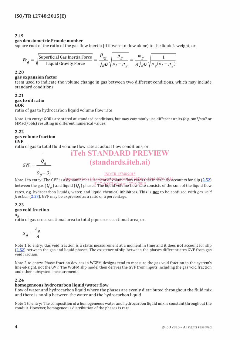
2.22gas volume fractionGVFratio of gas to total fluid volume flow rate at actual flow conditions, or
GVF =
+
�Q
Q Q
g
g l
. .
Note 1 to entry: The GVF is a dynamic measurement of volume flow rates that inherently accounts for slip (2.52) between the gas ( �Qg ) and liquid ( �Ql ) phases. The liquid volume flow rate consists of the sum of the liquid flow rates, e.g. hydrocarbon liquids, water, and liquid chemical inhibitors. This is not to be confused with gas void fraction (2.23). GVF may be expressed as a ratio or a percentage.
2.23gas void fractionαgratio of gas cross sectional area to total pipe cross sectional area, or
α ggA
A=
Note 1 to entry: Gas void fraction is a static measurement at a moment in time and it does not account for slip (2.52) between the gas and liquid phases. The existence of slip between the phases differentiates GVF from gas void fraction.
Note 2 to entry: Phase fraction devices in WGFM designs tend to measure the gas void fraction in the system’s line-of-sight, not the GVF. The WGFM slip model then derives the GVF from inputs including the gas void fraction and other subsystem measurements.
2.24homogeneous hydrocarbon liquid/water flowflow of water and hydrocarbon liquid where the phases are evenly distributed throughout the fluid mix and there is no slip between the water and the hydrocarbon liquid
Note 1 to entry: The composition of a homogeneous water and hydrocarbon liquid mix is constant throughout the conduit. However, homogeneous distribution of the phases is rare.
4 © ISO 2015 – All rights reserved
iTeh STANDARD PREVIEW(standards.iteh.ai)
ISO/TR 12748:2015https://standards.iteh.ai/catalog/standards/sist/91df86a9-d46d-4926-b341-
5117a600021c/iso-tr-12748-2015
ISO/TR 12748:2015(E)
2.25infraredelectromagnetic radiation with longer wavelengths than visible light
2.26intermittent flowunsteady flow, where the GVF varies with time, e.g. slug flow
2.27line conditions (actual, process, or operating conditions)thermodynamic conditions of the fluid passing through the meter, i.e. the fluid conditions at line (metering device) pressure and temperature
2.28liquid densiometric Froude numbersquare root of the ratio of the liquid flow inertia (if it were to flow alone) to the liquid’s weight, or
Fr Ul = =
Superficial Liquid Inertia Force
Liquid Gravity Force
__
( )sl l
l g
l
l l ggD
m
A gD
ρ
ρ ρ ρ ρ ρ−=
−1
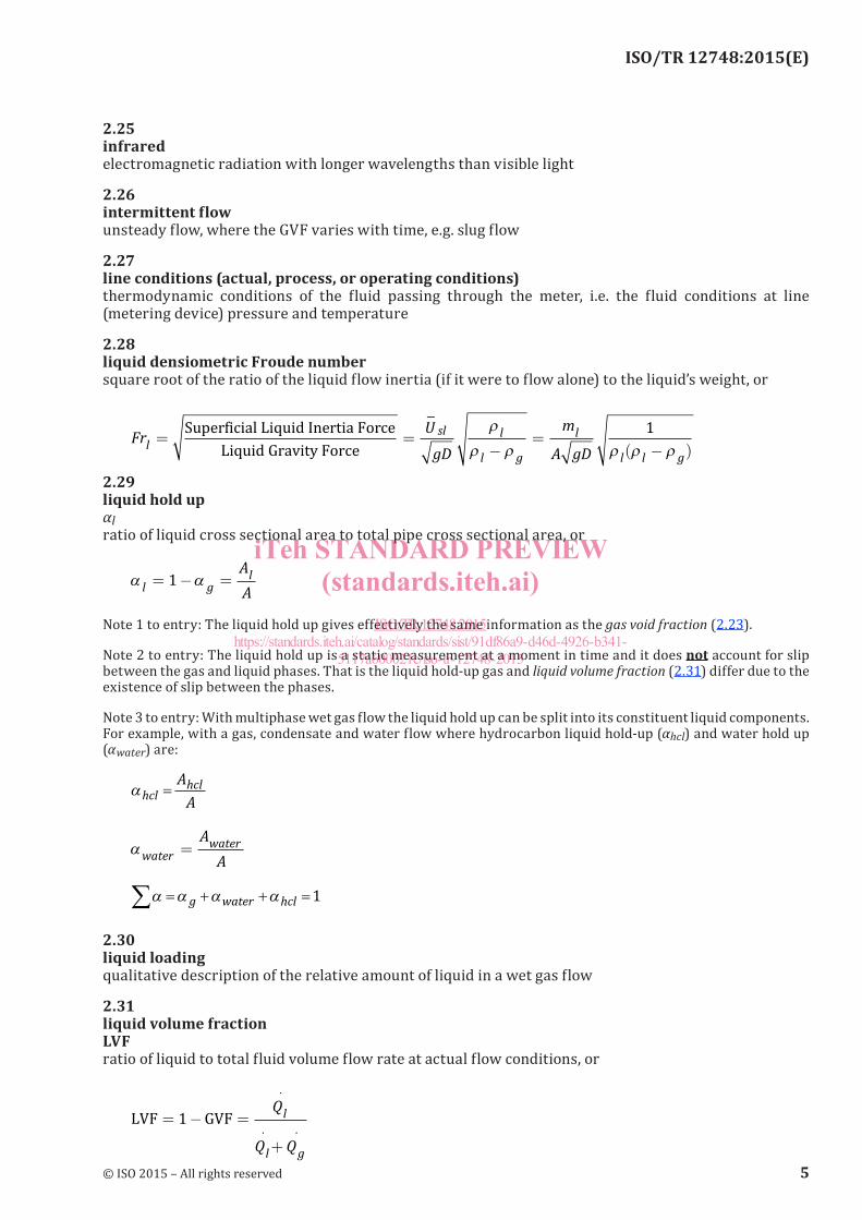
2.29liquid hold upαlratio of liquid cross sectional area to total pipe cross sectional area, or
α αl glA
A= − =1
Note 1 to entry: The liquid hold up gives effectively the same information as the gas void fraction (2.23).
Note 2 to entry: The liquid hold up is a static measurement at a moment in time and it does not account for slip between the gas and liquid phases. That is the liquid hold-up gas and liquid volume fraction (2.31) differ due to the existence of slip between the phases.
Note 3 to entry: With multiphase wet gas flow the liquid hold up can be split into its constituent liquid components. For example, with a gas, condensate and water flow where hydrocarbon liquid hold-up (αhcl) and water hold up (αwater) are:
αhclhclAA
=
αwaterwaterAA
=
α α α α= + + =∑ g water hcl 1
2.30liquid loadingqualitative description of the relative amount of liquid in a wet gas flow
2.31liquid volume fractionLVFratio of liquid to total fluid volume flow rate at actual flow conditions, or
LVF GVF= − =
+
1Q
Q Q
l
l g
.
. .
© ISO 2015 – All rights reserved 5
iTeh STANDARD PREVIEW(standards.iteh.ai)
ISO/TR 12748:2015https://standards.iteh.ai/catalog/standards/sist/91df86a9-d46d-4926-b341-
5117a600021c/iso-tr-12748-2015
ISO/TR 12748:2015(E)
Note 1 to entry: The LVF is a dynamic measurement of volume flow rates that inherently accounts for slip between the gas ( �Qg ) and liquid ( �Ql ) phases. The liquid volume flow rate consists of the sum of the liquid flow rates (for example, hydrocarbon liquids, water, and liquid chemical inhibitors). This is not to be confused with liquid hold up (2.29). LVF may be expressed as a ratio or a percentage.
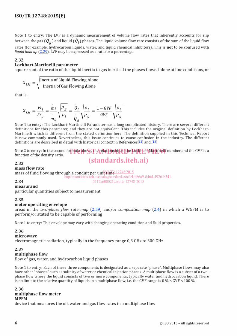
2.32Lockhart-Martinelli parametersquare root of the ratio of the liquid inertia to gas inertia if the phases flowed alone at line conditions, or
XLM =Inertia of Liquid Flowing Alone
Inertia of Gas Flowing AAlone
that is:
XFrFr
m
m
Q
Q
GVFGVFLM
l
g
l
g
g
l
l
g
l
g
l
g= = = =
−.
.
.
.
ρ
ρ
ρ
ρ
ρ
ρ1
Note 1 to entry: The Lockhart-Martinelli Parameter has a long complicated history. There are several different definitions for this parameter, and they are not equivalent. This includes the original definition by Lockhart-Martinelli which is different from the stated definition here. The definition supplied in this Technical Report is now commonly used. Nevertheless, this issue continues to cause confusion in the industry. The different definitions are described in detail with historical context in References[12] and.[13]
Note 2 to entry: In the second formula above, the relationship of the Lockhart-Martinelli number and the GVF is a function of the density ratio.
2.33mass flow ratemass of fluid flowing through a conduit per unit time
2.34measurandparticular quantities subject to measurement
2.35meter operating envelopeareas in the two-phase flow rate map (2.59) and/or composition map (2.4) in which a WGFM is to perform/or stated to be capable of performing
Note 1 to entry: This envelope may vary with changing operating condition and fluid properties.
2.36microwaveelectromagnetic radiation, typically in the frequency range 0,3 GHz to 300 GHz
2.37multiphase flowflow of gas, water, and hydrocarbon liquid phases
Note 1 to entry: Each of these three components is designated as a separate “phase”. Multiphase flows may also have other “phases” such as salinity of water or chemical injection phases. A multiphase flow is a subset of a two-phase flow where the liquid consists of two or more components, typically water and hydrocarbon liquid. There is no limit to the relative quantity of liquids in a multiphase flow, i.e. the GVF range is 0 % < GVF < 100 %.
2.38multiphase flow meterMPFMdevice that measures the oil, water and gas flow rates in a multiphase flow
6 © ISO 2015 – All rights reserved
iTeh STANDARD PREVIEW(standards.iteh.ai)
ISO/TR 12748:2015https://standards.iteh.ai/catalog/standards/sist/91df86a9-d46d-4926-b341-
5117a600021c/iso-tr-12748-2015

ISO/TR 12748:2015(E)
2.39multiphase/phase fraction devicedevice that measures the phase area fractions of the individual phases of a multiphase flow
Note 1 to entry: These devices tend to measure the area occupied by a particular phase across a given cross-sectional area. This is not the same information as the phase volume flow rate ratios due to the existence of a slip (2.52).
2.40oil continuous liquidoil external emulsionliquid flow consisting of the two “phases”, hydrocarbon liquid and water, where the hydrocarbon liquid phase encases the water phase suspended in water droplets in the hydrocarbon liquid phase
2.41operating envelopesee 2.35
2.42over-readingratio of a single-phase gas flow meter’s erroneous gas mass flow rate prediction (i.e. the “apparent gas mass flow rate”) to the actual dry gas mass flow rate
Note 1 to entry: In the case of DP devices, this is often approximated to the square root of the wet gas to dry gas DP ratio.
2.43permittivitymeasure of the ability of a dielectric medium to be electrically polarized when exposed to an electric field
2.44phaseused in WGFM applications to describe each of the three components gas, water and hydrocarbon liquid. Other components such as glycol and methanol can also be referred to as “phases”
2.45phase flow rateamount (in mass or volume) of a specific phase passing a referenced point in the conduit per unit time
2.46phase mass fractionratio of the mass flow rate of one phase to the total mass flow rate
2.47production envelopecollection of possible well production trajectories (gas flow rates and liquid flow rates) over time in the two-phase flow rate map (2.59), see Figure 23
2.48relative humidityratio of water liquid vapour present in a gaseous fluid relative to the maximum (or saturated) amount of water liquid vapour possible for that given gaseous fluid to hold at a given thermodynamic condition
2.49Reynolds numberReratio of the inertial to viscous forces, or
Re = =ρµ πµU D m
D.
.4 �
© ISO 2015 – All rights reserved 7
iTeh STANDARD PREVIEW(standards.iteh.ai)
ISO/TR 12748:2015https://standards.iteh.ai/catalog/standards/sist/91df86a9-d46d-4926-b341-
5117a600021c/iso-tr-12748-2015