technical information nivotester ftc625 - axon …h literature/tis/menu/docs/tis/level... · to a...
TRANSCRIPT
TI 370F/00/en
Technical Information
Nivotester FTC625 Level limit switchWith Intrinsically Safe Signal Circuit for Connectionto a Capacitance Sensor
Applications
• Level limit detection in tanks containing liquids and silos containing bulk solids. For capacitance level probes, which may also be applied in hazardous areas of category ATEX II (1) GD
• Overspill protection for tanks containing flammable or non-flammable fluids hazardous to water
• Dry running protection for pumps
Your benefits
• Intrinsically safe signal circuit [EEx ia] IIC for using sensors in hazardous areas
• Calibration using operating keys• High functional safety thanks to:
– Fail-safe PFM technology– Cable monitoring up to sensor with EC27Z– Checkable relay function
• Compact housing for easy series mounting on a standard DIN rail in the cabinet
• Pluggable terminal blocks make wiring easy• RS485 interface for connection, e.g. by Fieldgate
technology, for remote monitoring• RS232 diagnosis socket with connection to, for
example, ToF Tool for reading out data • Can be used also with EC16Z and EC17Z• Cyclical self-monitoring with EC27Z• Protection against maloperation and manipulation
– Every change in the switch setting triggers a red LED signal and a fault message
• Full- or empty push button calibration
Nivotester FTC625
2
Table of contents
Function and system design. . . . . . . . . . . . . . . . . . . . . 3Measuring principle . . . . . . . . . . . . . . . . . . . . . . . . . . . . . . . . . . . 3Measuring system . . . . . . . . . . . . . . . . . . . . . . . . . . . . . . . . . . . . . 5
Input . . . . . . . . . . . . . . . . . . . . . . . . . . . . . . . . . . . . . . 6Measured variable . . . . . . . . . . . . . . . . . . . . . . . . . . . . . . . . . . . . 6Measuring range . . . . . . . . . . . . . . . . . . . . . . . . . . . . . . . . . . . . . . 6Input signal . . . . . . . . . . . . . . . . . . . . . . . . . . . . . . . . . . . . . . . . . 6
Output . . . . . . . . . . . . . . . . . . . . . . . . . . . . . . . . . . . . . 6Output signal . . . . . . . . . . . . . . . . . . . . . . . . . . . . . . . . . . . . . . . . 6Signal on alarm . . . . . . . . . . . . . . . . . . . . . . . . . . . . . . . . . . . . . . 6Galvanic isolation . . . . . . . . . . . . . . . . . . . . . . . . . . . . . . . . . . . . . 6Overvoltage category as per EN 61010 . . . . . . . . . . . . . . . . . . . . . 6Protection class . . . . . . . . . . . . . . . . . . . . . . . . . . . . . . . . . . . . . . 6
Power supply. . . . . . . . . . . . . . . . . . . . . . . . . . . . . . . . 7Electrical connection . . . . . . . . . . . . . . . . . . . . . . . . . . . . . . . . . . 7Supply voltage . . . . . . . . . . . . . . . . . . . . . . . . . . . . . . . . . . . . . . . 7Power consumption . . . . . . . . . . . . . . . . . . . . . . . . . . . . . . . . . . . 7
Operating conditions (installation conditions) . . . . . . . 8Installation instructions . . . . . . . . . . . . . . . . . . . . . . . . . . . . . . . . . 8
Operating conditions (environmental conditions) . . . . 9Installation location . . . . . . . . . . . . . . . . . . . . . . . . . . . . . . . . . . . 9Permitted ambient temperatures . . . . . . . . . . . . . . . . . . . . . . . . . . 9Climatic and mechanical application class . . . . . . . . . . . . . . . . . . . 9Degree of protection . . . . . . . . . . . . . . . . . . . . . . . . . . . . . . . . . . . 9Electromagnetic Compatibility (EMC) . . . . . . . . . . . . . . . . . . . . . . 9
Mechanical construction . . . . . . . . . . . . . . . . . . . . . . 10Design, dimensions . . . . . . . . . . . . . . . . . . . . . . . . . . . . . . . . . . 10Weight . . . . . . . . . . . . . . . . . . . . . . . . . . . . . . . . . . . . . . . . . . . . 11Materials . . . . . . . . . . . . . . . . . . . . . . . . . . . . . . . . . . . . . . . . . . 11Terminals . . . . . . . . . . . . . . . . . . . . . . . . . . . . . . . . . . . . . . . . . . 11
Human interface . . . . . . . . . . . . . . . . . . . . . . . . . . . . 12Display elements . . . . . . . . . . . . . . . . . . . . . . . . . . . . . . . . . . . . 12Operating elements . . . . . . . . . . . . . . . . . . . . . . . . . . . . . . . . . . 12Operating concept . . . . . . . . . . . . . . . . . . . . . . . . . . . . . . . . . . . 12Remote operation . . . . . . . . . . . . . . . . . . . . . . . . . . . . . . . . . . . . 13
Certificates and approvals . . . . . . . . . . . . . . . . . . . . . 14CE mark . . . . . . . . . . . . . . . . . . . . . . . . . . . . . . . . . . . . . . . . . . 14Ex approval . . . . . . . . . . . . . . . . . . . . . . . . . . . . . . . . . . . . . . . . 14Type of protection . . . . . . . . . . . . . . . . . . . . . . . . . . . . . . . . . . . 14Overspill protection . . . . . . . . . . . . . . . . . . . . . . . . . . . . . . . . . . 14Other standards and regulations . . . . . . . . . . . . . . . . . . . . . . . . . 14
Ordering information. . . . . . . . . . . . . . . . . . . . . . . . . 14Nivotester FTC625 . . . . . . . . . . . . . . . . . . . . . . . . . . . . . . . . . . 14
Accessories . . . . . . . . . . . . . . . . . . . . . . . . . . . . . . . . 15Protective housing . . . . . . . . . . . . . . . . . . . . . . . . . . . . . . . . . . . 15Cable . . . . . . . . . . . . . . . . . . . . . . . . . . . . . . . . . . . . . . . . . . . . . 15
Supplementary Documentation . . . . . . . . . . . . . . . . . 15System Information (SI) . . . . . . . . . . . . . . . . . . . . . . . . . . . . . . . 15Technical Information (TI) . . . . . . . . . . . . . . . . . . . . . . . . . . . . . 15Operating Instructions (KA) . . . . . . . . . . . . . . . . . . . . . . . . . . . . 16Certificates . . . . . . . . . . . . . . . . . . . . . . . . . . . . . . . . . . . . . . . . 16
Nivotester FTC625
3
Function and system design
Measuring principle Function
Probe and tank (or ground tube/counterpotential) form a capacitor whose capacitance changes with the level of the product. The electronic insert converts the capacitance change into a frequency change, which switches the output relay in the Nivotester FTC625.
Signal transmission
The Nivotester FTC625 limit switch's intrinsically safe signal input is galvanically isolated from the mains and from the output. The Nivotester supplies the capacitance sensor with power via a two-wire cable with direct current and receives a frequency from it which signals whether the level limit has been reached or not. Here, the transmitter superimposes current pulses (PFM signals) with a pulse width of approx. 200 µs and an amperage of approx. 10 mA on the supply current.
Signal analysis
The Nivotester analyses the frequency and switches the output relay for the level alarm. The switching state of the relay is displayed on the front panel of the Nivotester by means of a yellow light emitting diode (left).
Fail-safe circuit
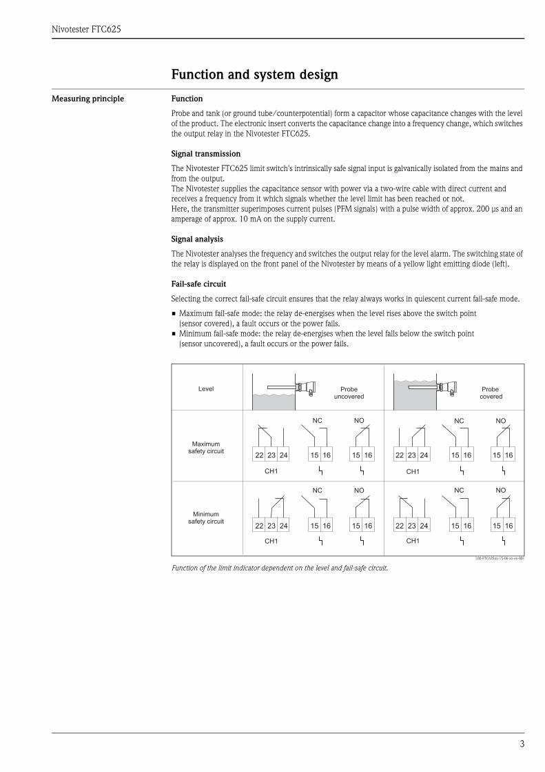
Selecting the correct fail-safe circuit ensures that the relay always works in quiescent current fail-safe mode.
• Maximum fail-safe mode: the relay de-energises when the level rises above the switch point (sensor covered), a fault occurs or the power fails.
• Minimum fail-safe mode: the relay de-energises when the level falls below the switch point (sensor uncovered), a fault occurs or the power fails.
L00-FTC625xx-15-06-xx-en-001
Function of the limit indicator dependent on the level and fail-safe circuit.
15 16 15 16
15 16 15 1622 23 24
22 23 24
22 23 24
22 23 2415 16 15 16
15 16 15 16
CH1
NC NO
CH1
NC NO
CH1
NC NO
CH1
NC NO
Probeuncovered
Probecovered
Level
Maximumsafety circuit
Minimumsafety circuit
Nivotester FTC625
4
Function monitoring
To increase operational safety, the Nivotester is equipped with a function monitoring facility. A fault is displayed by the red light emitting diode and de-energises the relay for the level alarm and the alarm relay. A fault is indicated if the Nivotester does not receive any more current pulses. This occurs, for example, when:
• there is a short-circuit• the signal line to the sensor is interrupted• the sensor electronics are defective• the Nivotester's input switching is defective
Permanent function monitoring is implemented by the EC27Z electronic insert. Here, the Nivotester sends a test pulse to the EC27Z, which then returns it. This occurs in one second cycles. If the frequency measurement is interrupted, the Nivotester triggers the alarm.
In order to ensure that in some applications a limit indication is not signalled before a fault message, the Nivotester is equipped with a switchable alarm priority (only in conjunction with EC27Z).
After calibration, every further change to the device configuration de-energises the relay. A fault message is signalled via the red LED.
Calibration key (red)
Calibration is carried out automatically by means of operating keys. This makes setting via rotary switches inapplicable.
Additional switch functions
• An adjustable switching delay of 0 ... 45 s allows for the relay to be switched with a delay when covering or uncovering the probe. In the opposite direction, each switching delay is 0.2 s.
• A 16-stage switch point shift allows for safe system operation even when using media that are prone to build-up.
The test/correction key (green):
• allows for a function check of the output relay and alarm relay.• confirms a change in the operating mode - e.g. by changing the switching delay after initial calibration.
This enables a correction of the operating mode without requiring recalibration. The changed settings are saved by pressing the operating key.
Diagnosis plug (RS232)
The RS232 interface serves as a PC interface and enables on-site operation using a laptop in conjunction with a ToF Tool.
RS485 interface
The RS485 interface enables, for example, connection to a Fieldgate, with which remote monitoring can also be performed via the Internet. This remotely monitors the probe frequency, for example in order to receive a message by e-mail should build-up occur and to initiate a new calibration.
Nivotester FTC625
5
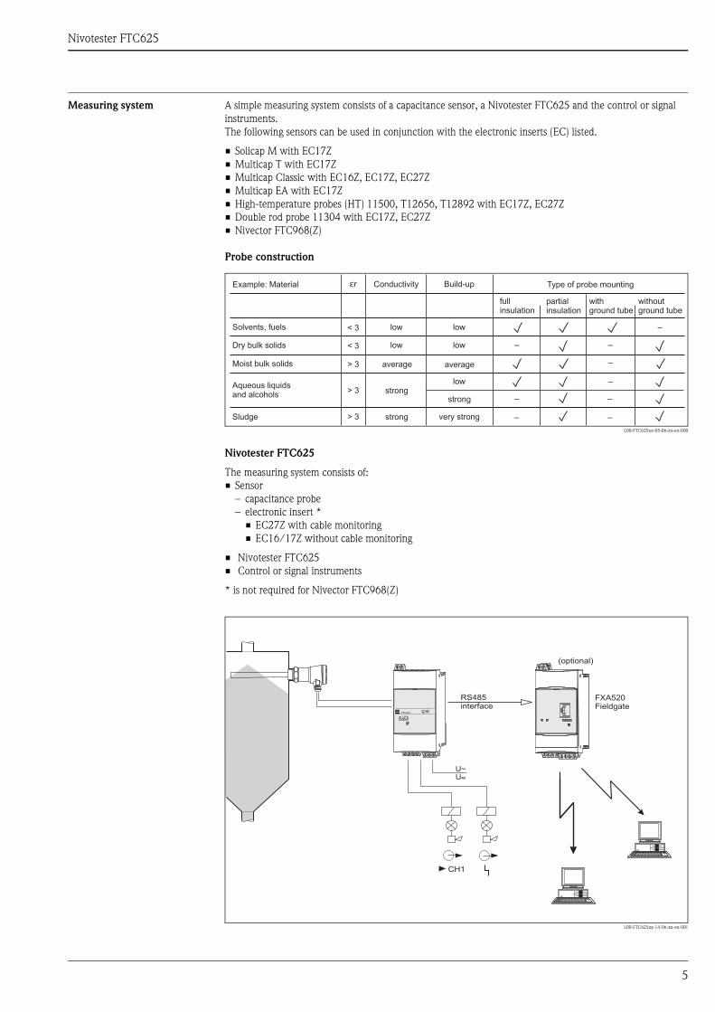
Measuring system A simple measuring system consists of a capacitance sensor, a Nivotester FTC625 and the control or signal instruments. The following sensors can be used in conjunction with the electronic inserts (EC) listed.
• Solicap M with EC17Z• Multicap T with EC17Z• Multicap Classic with EC16Z, EC17Z, EC27Z• Multicap EA with EC17Z• High-temperature probes (HT) 11500, T12656, T12892 with EC17Z, EC27Z• Double rod probe 11304 with EC17Z, EC27Z• Nivector FTC968(Z)
Probe construction
Nivotester FTC625
The measuring system consists of:• Sensor
– capacitance probe– electronic insert *
• EC27Z with cable monitoring• EC16/17Z without cable monitoring
• Nivotester FTC625• Control or signal instruments
* is not required for Nivector FTC968(Z)
L00-FTC625xx-14-06-xx-en-001
L00-FTC625xx-05-06-xx-en-000
–
–
–
–
–
–
–
–
–
< 3
εr
< 3
> 3
> 3
> 3Sludge
Aqueous liquidsand alcohols
Moist bulk solids
Dry bulk solids
Solvents, fuels low
Conductivity Build-up Type of probe mounting
fullinsulation
partialinsulation
withground tube
withoutground tube
Example: Material
low
low low
average average
stronglow
strong
strong very strong
U~U–~
CH1
FTC625T
RS485interface
FXA520Fieldgate
(optional)
Nivotester FTC625
6
Input
Measured variable The limit signal is generated at minimum or maximum level, depending on the selection
Measuring range The measuring range is dependent on the mounting location of the probes.
Input signal • FTC625 input: galvanically isolated from power supply and output• Type of protection: intrinsic safety [EEx ia] IIC• Connectable sensors:
Solicap M with EC17ZMulticap T with EC17ZMulticap Classic with EC16Z, EC17Z, EC27ZMulticap EA with EC17ZHigh-temperature probes (HT) 11500, T12656, T12892 with EC17Z, EC27ZDouble rod probe 11304 with EC17Z, EC27ZNivector FTC968(Z)
• Sensor's power supply: from Nivotester FTC625 • Connecting cable: two-wire, screening not required, except for strong electromagnetic interferences
(see also page 6)• Cable resistance: max. 25 Ω per wire• Signal transmission: pulse-frequency modulation (PFM)
Output
Output signal • Relay output: a potential-free change-over contact for the level alarm• RS485 interface for connection to, for example, Fieldgate (remote monitoring)• Quiescent current fail-safe circuit: minimum/maximum fail-safe mode can be selected using the DIL switch• Alarm relay: potential-free change-over contact for fault indication, only two contacts made
(NC or NO contact)• Switching delay: 0...45 s
relay switches when covering or uncovering the probe, depending on the setting• Switching capacity of relay contacts:
U~ maximum 253 VI~ maximum 2 AP~ maximum 500 VA at cos ϕ ≥ 0.7
U- maximum 40 VI- maximum 2 AP- maximum 80 W
• Service life: at least 105 switching cycles at maximum contact load• Function indicator: light emitting diodes for operation/communication, level alarm, fault and level signal
(lights up as long as the probe is covered)
Signal on alarm Limit relay de-energised; fault indication via red LED, alarm relay de-energised
Galvanic isolation All input and output channels and relay contacts are galvanically safe isolated from each other.When making a simultaneous connection from the power supply circuit to the function's extra-low voltage or to the alarm relay's contacts, safe galvanic isolation is guaranteed up to a voltage of 150 V AC.
Overvoltage category as per EN 61010
II
Protection class II (double or increased insulation)
Nivotester FTC625
7
Power supply
Electrical connection Terminal blocks
The removable terminal blocks are isolated after intrinsically safe connections (top of device) and non-intrinsically safe connections (bottom of device). Furthermore, the terminal blocks are also colour-coded. Blue is for the intrinsically safe area and grey for the non-intrinsically safe area. These distinctions allow for safe cable routing.
Sensor connection
(To the upper, blue terminal blocks).Use a usual commercial instrument cable or multi-core cable for measuring purposes for the two-wire connecting cable between the Nivotester FTC625 and the sensor. Cable resistance of maximum 25 Ω per wire.If strong electromagnetic interferences have to be expected, e.g. from machines or radios, a screened cable must be used. Only connect the screening to the grounding connection in the sensor, not to the Nivotester.
Using the sensor in hazardous areas
Compliance with the national explosion protection regulations for the design and routing of the intrinsically safe signal cable is mandatory.High-reliability values for capacitance and inductance are contained in Safety Instructions XA 195F.
Connection of signal and control instruments
(To the lower, grey terminal blocks) The relay function must be observed dependent on the level and fail-safe circuit.If a device with high inductance (e.g. contactor, solenoid valve, etc.) is connected, a spark suppressor must be added to protect the relay contact.
Supply voltage connection
(To the lower, grey terminal blocks)For voltage versions, see the Ordering information.A fuse (T 200mA) is built in to the power supply circuit, so that it is not necessary to pre-connect a fine-wire fuse. The Nivotester is equipped with reverse polarity protection.
Supply voltage Alternating current version (AC):
• Voltage ranges: 85...253 V, 50/60 Hz
Direct current version (DC):
• Voltage range: 20...30 V AC / 20...60 V DC• Power supply direct current: maximum 100 mA • Permitted residual ripple within the tolerance: Uss = maximum 2 V
Power consumption AC version
maximum 6.0 VA
DC version
maximum 2.0 W (at Umin 20 V)
Nivotester FTC625
8
Operating conditions (installation conditions)
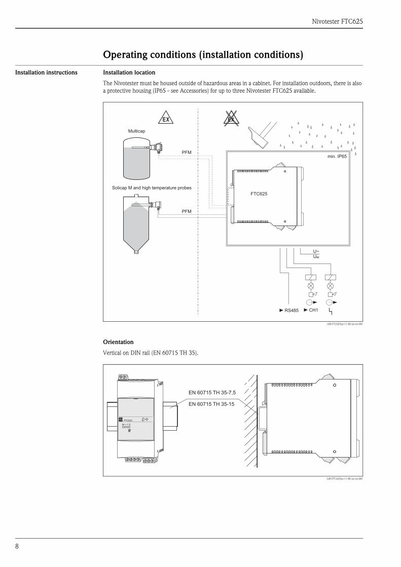
Installation instructions Installation location
The Nivotester must be housed outside of hazardous areas in a cabinet. For installation outdoors, there is also a protective housing (IP65 - see Accessories) for up to three Nivotester FTC625 available.
L00-FTC625xx-11-06-xx-en-001
Orientation
Vertical on DIN rail (EN 60715 TH 35).
L00-FTC625xx-11-06-xx-xx-001
EX EX
PFM
PFM
U~U–~
CH1
FTC625
RS485
min. IP65
Solicap M and high temperature probes
Multicap
EN 60715 35-7,5
EN 60715 35-15
TH
TH
FTC625T
Nivotester FTC625
9
Operating conditions (environmental conditions)
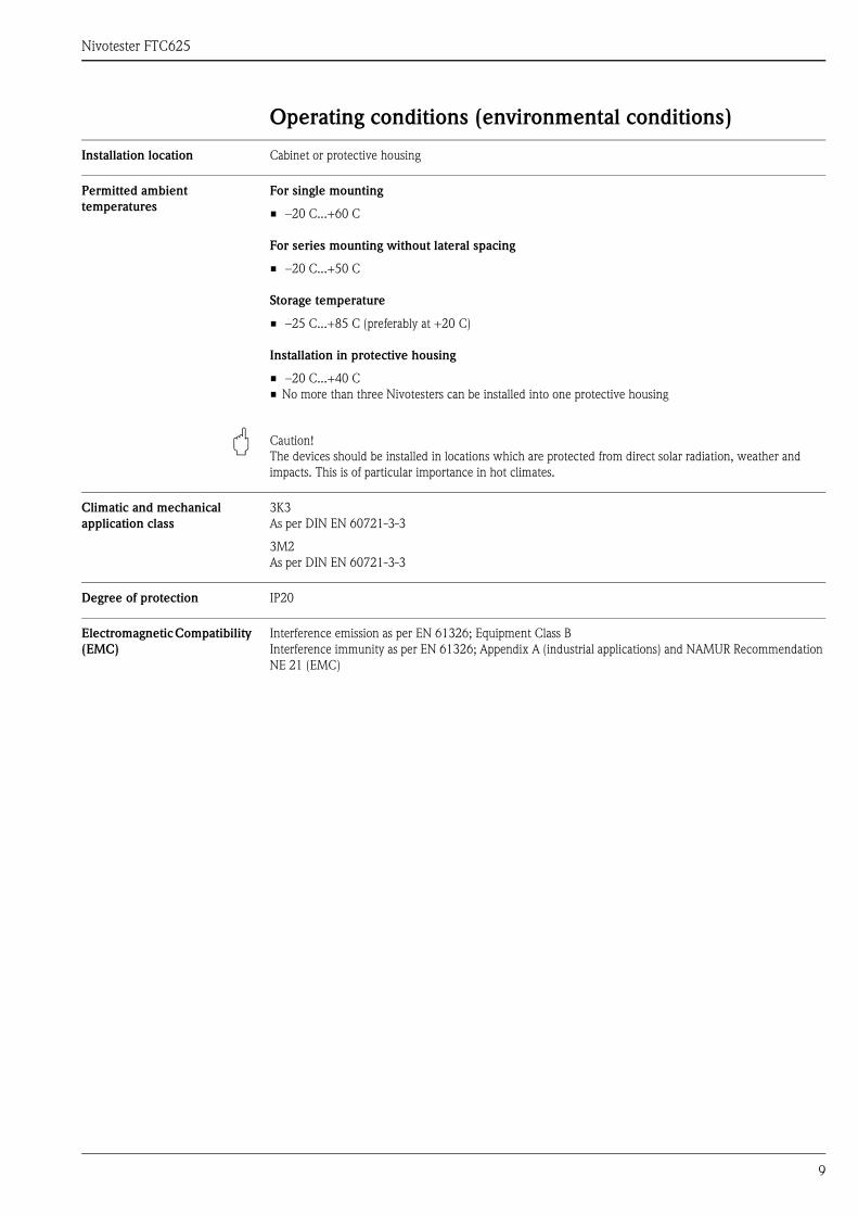
Installation location Cabinet or protective housing
Permitted ambient temperatures
For single mounting
• –20 C...+60 C
For series mounting without lateral spacing
• –20 C...+50 C
Storage temperature
• –25 C...+85 C (preferably at +20 C)
Installation in protective housing
• –20 C...+40 C• No more than three Nivotesters can be installed into one protective housing
" Caution! The devices should be installed in locations which are protected from direct solar radiation, weather and impacts. This is of particular importance in hot climates.
Climatic and mechanical application class
3K3As per DIN EN 60721-3-3
3M2As per DIN EN 60721-3-3
Degree of protection IP20
Electromagnetic Compatibility (EMC)
Interference emission as per EN 61326; Equipment Class BInterference immunity as per EN 61326; Appendix A (industrial applications) and NAMUR Recommendation NE 21 (EMC)
Nivotester FTC625
10
Mechanical construction
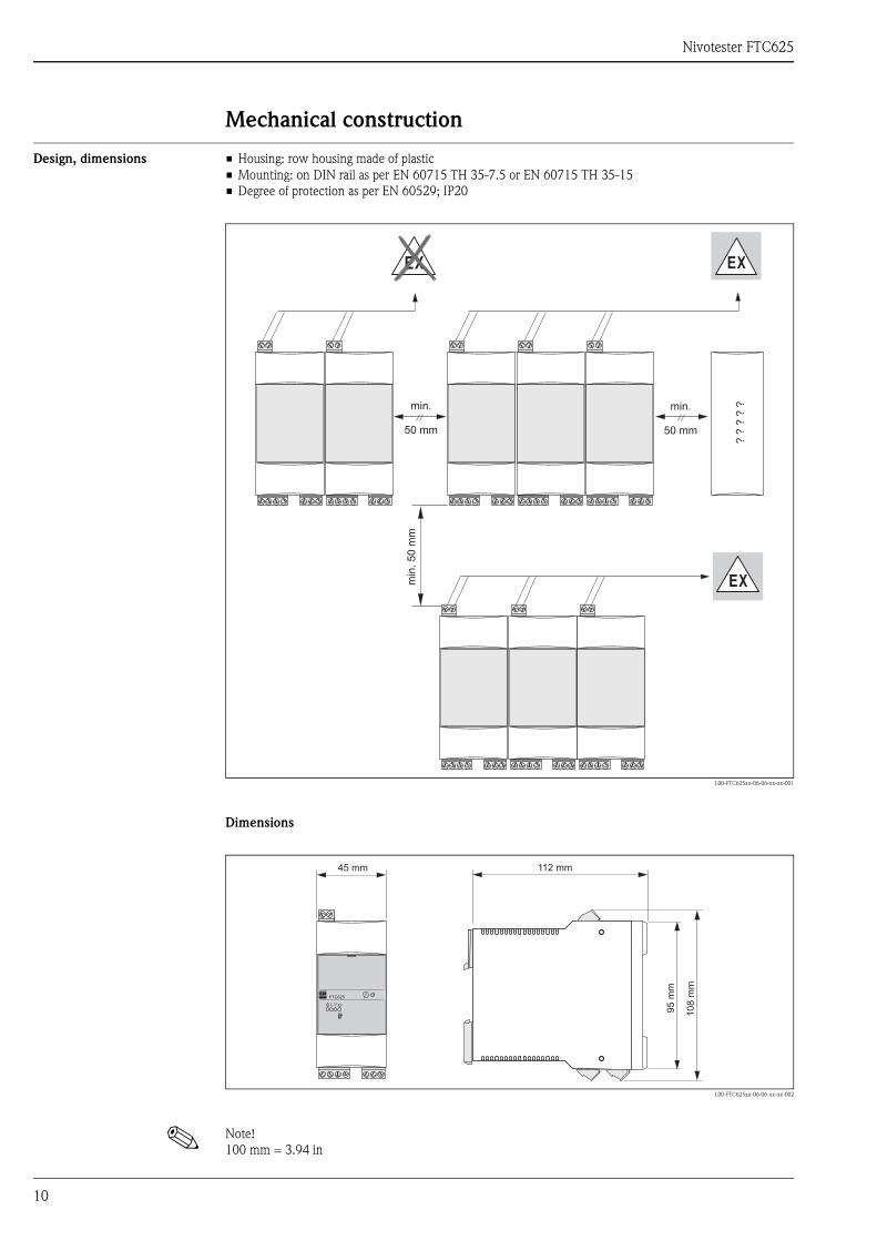
Design, dimensions • Housing: row housing made of plastic• Mounting: on DIN rail as per EN 60715 TH 35-7.5 or EN 60715 TH 35-15• Degree of protection as per EN 60529; IP20
L00-FTC625xx-06-06-xx-xx-001
Dimensions
L00-FTC625xx-06-06-xx-xx-002
! Note! 100 mm = 3.94 in
min
.5
0m
mmin.
50 mm
min.
50 mm
??
??
?
EX
EX
EX
112 mm
95
mm
108
mm
45 mm
FTC625T
Nivotester FTC625
11
Weight approx. 250 g
Materials Housing
• Polycarbonate Colour: light grey, RAL 7035
Front cover
• Polypropylene PPNColour: blue
Fixing bracket (for securing on the DIN rail)
• Polyamide PA6 Colour: black, RAL 9005
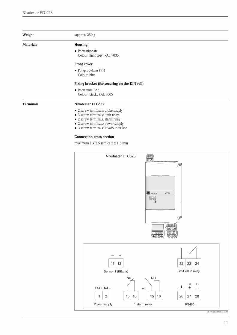
Terminals Nivotester FTC625
• 2 screw terminals: probe supply• 3 screw terminals: limit relay• 2 screw terminals: alarm relay• 2 screw terminals: power supply• 3 screw terminals: RS485 interface
Connection cross-section
maximum 1 x 2.5 mm or 2 x 1.5 mm
L00-FTC625xx-04-06-xx-en-001
Nivotester FTC625
L1/L+ N/L–
RS485
A B
+ –
– +
22 23 24
26 27 28
11 12
15 16 15 161 2
1 2 15
16
22
23
24
26
27
28
11
12
FTC625T
NC NO
Sensor 1 (EEx ia) Limit value relay
Power supply 1 alarm relay
or
Nivotester FTC625
12
Human interface
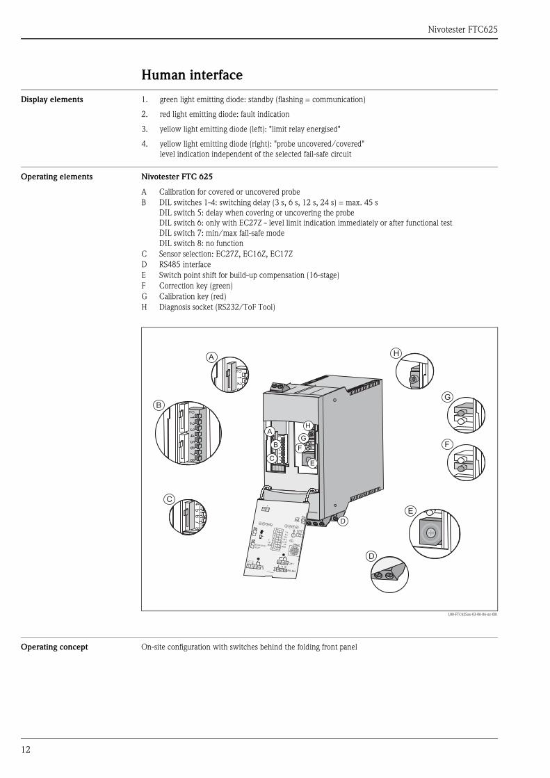
Display elements 1. green light emitting diode: standby (flashing = communication)
2. red light emitting diode: fault indication
3. yellow light emitting diode (left): "limit relay energised"
4. yellow light emitting diode (right): "probe uncovered/covered"level indication independent of the selected fail-safe circuit
Operating elements Nivotester FTC 625
L00-FTC625xx-03-06-06-xx-001
Operating concept On-site configuration with switches behind the folding front panel
A Calibration for covered or uncovered probeB DIL switches 1-4: switching delay (3 s, 6 s, 12 s, 24 s) = max. 45 s
DIL switch 5: delay when covering or uncovering the probeDIL switch 6: only with EC27Z - level limit indication immediately or after functional test DIL switch 7: min/max fail-safe modeDIL switch 8: no function
C Sensor selection: EC27Z, EC16Z, EC17ZD RS485 interface E Switch point shift for build-up compensation (16-stage)F Correction key (green)G Calibration key (red)H Diagnosis socket (RS232/ToF Tool)
12
34
56
78
ON
A
B
C
H
G
D
F
E
RS 485
22 23 24
11 12
2826 27
CH1
15 16
N
1 2
L1L+ L-
- +
A B
1
2
3
4
5
6
7
8
3 s6 s
12 s24 s
S
FPMAX
tMIN
LP
T
OffsetEC16/ EC17EC27
2
1
2
1
12
ON
A1
23
45
67
8ON
B
45
67
8
C
D
E
F
G
H
Nivotester FTC625
13
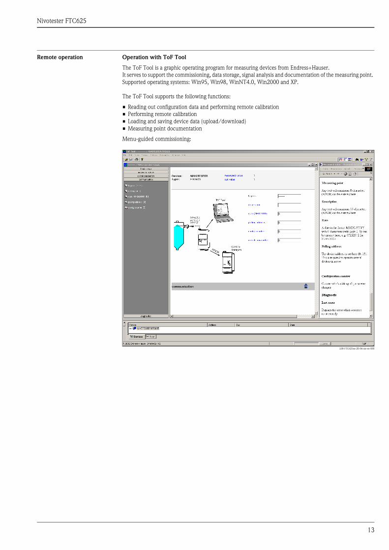
Remote operation Operation with ToF Tool
The ToF Tool is a graphic operating program for measuring devices from Endress+Hauser.It serves to support the commissioning, data storage, signal analysis and documentation of the measuring point. Supported operating systems: Win95, Win98, WinNT4.0, Win2000 and XP.
The ToF Tool supports the following functions:
• Reading out configuration data and performing remote calibration• Performing remote calibration• Loading and saving device data (upload/download)• Measuring point documentation
Menu-guided commissioning:
L00-FTC625xx-20-06-xx-en-000
Nivotester FTC625
14
Certificates and approvals
CE mark The Nivotester meets all the statutory requirements arising from EC directives.Endress+Hauser confirms the successful testing of the device by affixing the CE symbol.
Ex approval Endress+Hauser Sales Centers provide information about the currently available versions for use in hazardous areas (ATEX EEx ia IIC; FM IS; CSA IS) All the relevant data for explosion protection is contained in separate Ex documentation(see: Supplementary Documentation), which can be requested.
Type of protection [EEx ia] IIC
Overspill protection WHG
Other standards and regulations
Other standards and regulations which were complied with during the conception and development of the Nivotester FTC625.
• EN 60529Degrees of protection provided by enclosures (IP code)
• EN 61010Safety requirements for electrical equipment for measurement, control and laboratory use
• EN 61326Interference emission (Equipment Class B), interference immunity (Appendix A - industrial applications)
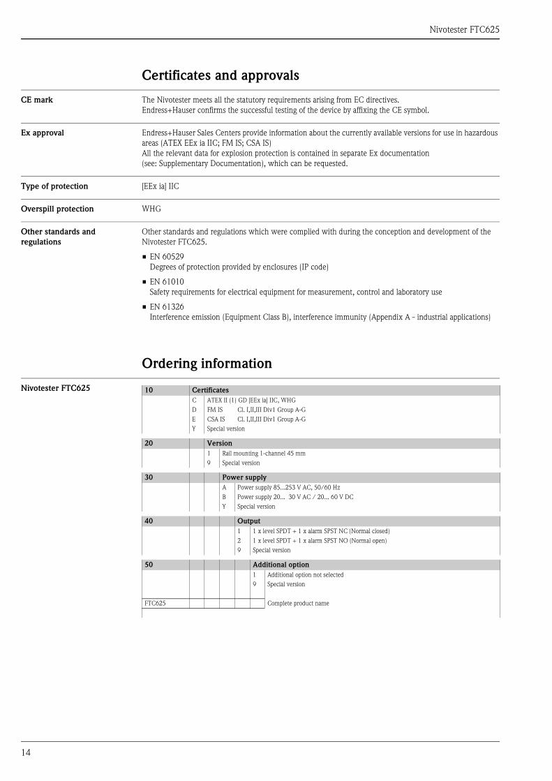
Ordering information
Nivotester FTC625 10 CertificatesC ATEX II (1) GD [EEx ia] IIC, WHGD FM IS Cl. I,II,III Div1 Group A-GE CSA IS Cl. I,II,III Div1 Group A-GY Special version
20 Version1 Rail mounting 1-channel 45 mm 9 Special version
30 Power supplyA Power supply 85...253 V AC, 50/60 HzB Power supply 20... 30 V AC / 20... 60 V DCY Special version
40 Output1 1 x level SPDT + 1 x alarm SPST NC (Normal closed)2 1 x level SPDT + 1 x alarm SPST NO (Normal open)9 Special version
50 Additional option1 Additional option not selected 9 Special version
FTC625 Complete product name
Nivotester FTC625
15
Accessories
Protective housing The protective housing in protection class IP66 is equipped with an integrated DIN rail and closed by a transparent cover, which can also be lead-sealed.
Dimensions:
W: 180 / H: 182 / D: 165
Technical Data:
• Ingress protection (EN 60529): IP66• Lower housing section: fibre-glass reinforced polycarbonate, grey• Upper housing section: polycarbonate, transparent• Cover screws: PA, 4 pieces, 2 of which are sealing• Seal: PU seal• Top-hat rail (EN 50022): galvanized• Cable entries: 5 pieces M 20x1,5
• Part number: 52010132
Cable Cable for connecting the Nivotester FTC625 to a PC (RS232/3.5 mm jack plug)
• Part number: 52013982(included in delivery)
Supplementary Documentation
System Information (SI) • Capacitance level measurementSI 001F/00
Technical Information (TI) Capacitance measuring devices
• Solicap MFTC51, FTC52, FTC53TI 362F/00
• Multicap T (America)DC12TA, DC11/16/21/26TAN, DC11/16/21/26TASTI 239F/00
• Multicap T (Europe)DC12TE, DC11/16/21/26TEN, DC11/16/21/26TESTI 240F/00
• Multicap ClassicDC11 TI 169F/00
• Multicap ClassicDC16 TI 096F/00
• Multicap ClassicDC21TI 208F/00
• High-temperature probe (HT)11500ZMTI 161F/00
• High-temperature probe (HT)T12656TI 117F/00
• High-temperature probe (HT)T12892TI 118F/00
Nivotester FTC625
• Double rod probe11304ZTI 052F/00
• NivectorFTC968, FTC968ZTI 037F/00
Electronic inserts
• EC16ZTI 170F/00
• EC17ZTI 268F/00
• EC27ZTI 269F/00
Protective housing
• Protective housingTI 367F/00
Fieldgate
• FXA320, FXA520TI 369F/00
Operating Instructions (KA) • NivotesterFTC625 KA 194F/00
Certificates ATEX:
• NivotesterFTC625XA 195F/00
WHG (DIBt):
• NivotesterFTC625ZE 211F/00
International Head Quarter
Endress+Hauser
GmbH+Co. KG
Instruments International
Colmarer Str. 6
79576 Weil am Rhein
Deutschland
Tel. +49 76 21 9 75 02
Fax +49 76 21 9 75 34 5
www.endress.com
TI370F/00/en/02.04SL/FM+SGML 6.0 ProMoDo