technical information deltatop dp61d, dp62d, dp63d · technical information deltatop dp61d, dp62d,...
TRANSCRIPT

TI425P/00/en/10.07
Technical Information
DeltatopDP61D, DP62D, DP63DDifferential pressure flow measurement with
Pitot tubes and Deltabar differential pressure transmitter
The universal measuring system for steam, gases and liquids
Application
• Flow measurement of gases, steam and liquids
• nominal diameters from DN 40 to DN 12000
• medium temperatures from -200 °C (-328 °F) to
1000 °C (1830 °F)
• pressure up to 420 bar (6300 psi)
• Compliant to DGRL 97/23/EC
• NACE compliant materials
Deltabar differential pressure transmitter
• Approvals for hazardous area:
ATEX, FM, CSA
• Relevant safety aspects: SIL
• Connection to all common process control systems:
Profibus, HART, Foundation Fieldbus
Your benefits
• selectable according to the application:
– operational compact version: minimizes installation
costs
– modular remote version: for demanding process
conditions (high temperature, high pressure) and
difficult installation conditions
• optimized for minimum pressure loss and highest
accuracy
• Deltabar differential pressure transmitter ready
adjusted
• display configured for flow rate, differential pressure or
0...100%
• suited for bidirectional measurements
• robust design; no moving parts
Deltatop DP61D, DP62D, DP63D
Table of Contents
Function and System Design . . . . . . . . . . . . . . . . . . . . 3 Deltatop DA62V: Shut-Off Valve (accessory) . . . . . . . 48
Measuring principle . . . . . . . . . . . . . . . . . . . . . . . . . . . . . . . . . . . 3
Flow calculation . . . . . . . . . . . . . . . . . . . . . . . . . . . . . . . . . . . . . . 4
Sizing and optimization . . . . . . . . . . . . . . . . . . . . . . . . . . . . . . . . 5
Selection and sizing tool "Applicator" . . . . . . . . . . . . . . . . . . . . . . 5
Sizing sheet - Data Sheet . . . . . . . . . . . . . . . . . . . . . . . . . . . . . . . 5
Selecting the differential pressure transmitter and the measuring cell
5
Temperature and pressure compensation . . . . . . . . . . . . . . . . . . . 6
Split range (expansion of the measuring range) . . . . . . . . . . . . . . . 8
Flow measurements in liquids . . . . . . . . . . . . . . . . . . . . . . . . . . . . 9
Flow measurement in gases . . . . . . . . . . . . . . . . . . . . . . . . . . . . . 9
Flow measurement in steam . . . . . . . . . . . . . . . . . . . . . . . . . . . . 10
Mounting positions . . . . . . . . . . . . . . . . . . . . . . . . . . 11
Versions . . . . . . . . . . . . . . . . . . . . . . . . . . . . . . . . . . . . . . . . . . . 11
Flow direction . . . . . . . . . . . . . . . . . . . . . . . . . . . . . . . . . . . . . . 11
Gas measurements . . . . . . . . . . . . . . . . . . . . . . . . . . . . . . . . . . . 11
Liquid measurements . . . . . . . . . . . . . . . . . . . . . . . . . . . . . . . . . 12
Steam measurements . . . . . . . . . . . . . . . . . . . . . . . . . . . . . . . . . 13
Installation and process conditions . . . . . . . . . . . . . . 14
Up- and downstream lengths . . . . . . . . . . . . . . . . . . . . . . . . . . . 14
Homogeneity . . . . . . . . . . . . . . . . . . . . . . . . . . . . . . . . . . . . . . . 14
Temperature, Pressure . . . . . . . . . . . . . . . . . . . . . . . . . . . . . . . . 14
Reynolds number . . . . . . . . . . . . . . . . . . . . . . . . . . . . . . . . . . . . 15
Temperature limits of the materials applied . . . . . . . . . . . . . . . . . 16
Pressure-temperature curves for flanges according to EN1092-1:2001
. . . . . . . . . . . . . . . . . . . . . . . . . . . . . . . . . . . . . . . . . . . . . . . . . . 18
Pressure-temperature curves for flanges according to ANSI B16.5-
2003 . . . . . . . . . . . . . . . . . . . . . . . . . . . . . . . . . . . . . . . . . . . . . 20
Mechanical construction . . . . . . . . . . . . . . . . . . . . . . 22
Probe profile/probe length . . . . . . . . . . . . . . . . . . . . . . . . . . . . . 22
Typical configurations . . . . . . . . . . . . . . . . . . . . . . . . . . . . . . . . . 23
Dimensions/weight . . . . . . . . . . . . . . . . . . . . . . . . . . . . . . . . . . 24
Process connection, Mounting nozzle . . . . . . . . . . . . . . . . . . . . . 28
Mounting nozzle extension . . . . . . . . . . . . . . . . . . . . . . . . . . . . 28
End support . . . . . . . . . . . . . . . . . . . . . . . . . . . . . . . . . . . . . . . . 28
Differential pressure connection . . . . . . . . . . . . . . . . . . . . . . . . . 29
Integrated temperature sensor . . . . . . . . . . . . . . . . . . . . . . . . . . 31
Overview of the product structures . . . . . . . . . . . . . . 32
Ordering information. . . . . . . . . . . . . . . . . . . . . . . . . 34
Product structure
Deltatop DP61D . . . . . . . . . . . . . . . . . . . . . . . . . . . . . . . . . . . . . 34
Product structure
Deltatop DP62D . . . . . . . . . . . . . . . . . . . . . . . . . . . . . . . . . . . . . 38
Product structure
Deltatop DP63D . . . . . . . . . . . . . . . . . . . . . . . . . . . . . . . . . . . . . 43
Accessories . . . . . . . . . . . . . . . . . . . . . . . . . . . . . . . . 47
Overview . . . . . . . . . . . . . . . . . . . . . . . . . . . . . . . . . . . . . . . . . . 47
2
Version: Valve
(DA62V-6...) . . . . . . . . . . . . . . . . . . . . . . . . . . . . . . . . . . . . . . . 48
Version: Gate valve
(DA62V-7...) . . . . . . . . . . . . . . . . . . . . . . . . . . . . . . . . . . . . . . . 50
Version: Ball valve
(DA62V-5...) . . . . . . . . . . . . . . . . . . . . . . . . . . . . . . . . . . . . . . . 50
Product structure
DA62V . . . . . . . . . . . . . . . . . . . . . . . . . . . . . . . . . . . . . . . . . . . 51
Deltatop DA62C: Condensate Pot (accessory) . . . . . . 52
Dimensions . . . . . . . . . . . . . . . . . . . . . . . . . . . . . . . . . . . . . . . . 52
Weight . . . . . . . . . . . . . . . . . . . . . . . . . . . . . . . . . . . . . . . . . . . 52
Product structure . . . . . . . . . . . . . . . . . . . . . . . . . . . . . . . . . . . . 53
Deltatop DA63M: Manifold (accessory) . . . . . . . . . . . 54
Usage . . . . . . . . . . . . . . . . . . . . . . . . . . . . . . . . . . . . . . . . . . . . 54
Version: 3-valve, forged . . . . . . . . . . . . . . . . . . . . . . . . . . . . . . . 55
Version: 3-valve, milled . . . . . . . . . . . . . . . . . . . . . . . . . . . . . . . 56
Version: 5-valve, milled, vent . . . . . . . . . . . . . . . . . . . . . . . . . . . 57
Version: 5-valve, forged, purge valve . . . . . . . . . . . . . . . . . . . . . 58
Version: 5-valve HT, forged, purge valve . . . . . . . . . . . . . . . . . . 59
Version: 3-valve, forged, IEC61518, both side . . . . . . . . . . . . . . 60
Version: 5-valve, forged, IEC61518, both side, vent . . . . . . . . . . 61
Product structure DA63M . . . . . . . . . . . . . . . . . . . . . . . . . . . . . 62
Deltatop DA62P: Purge Unit . . . . . . . . . . . . . . . . . . . 63
Usage . . . . . . . . . . . . . . . . . . . . . . . . . . . . . . . . . . . . . . . . . . . . 63
Systemaufbau . . . . . . . . . . . . . . . . . . . . . . . . . . . . . . . . . . . . . . . 63
Mounting . . . . . . . . . . . . . . . . . . . . . . . . . . . . . . . . . . . . . . . . . 63
Triggering . . . . . . . . . . . . . . . . . . . . . . . . . . . . . . . . . . . . . . . . . 63
Technical data . . . . . . . . . . . . . . . . . . . . . . . . . . . . . . . . . . . . . . 64
Dimensions . . . . . . . . . . . . . . . . . . . . . . . . . . . . . . . . . . . . . . . . 65
Product structure DA62P . . . . . . . . . . . . . . . . . . . . . . . . . . . . . . 65
Oval flange adapter PZO for Deltabar S . . . . . . . . . . . 66
Dimensions . . . . . . . . . . . . . . . . . . . . . . . . . . . . . . . . . . . . . . . . 66
Product structure PZO . . . . . . . . . . . . . . . . . . . . . . . . . . . . . . . . 66
Sizing Sheet - Data Sheet . . . . . . . . . . . . . . . . . . . . . . 67
Instructions for the completion of the sizing sheet - data sheet . . 69
Endress+Hauser

Deltatop DP61D, DP62D, DP63D
Function and System Design
Measuring principle
P01-DOxxx-15-00-00-xx-002
The front of the pitot tube is exposed to the static pressure pstat plus the dynamic pressure pdyn. The back of the
tube is exposed only to the static pressure pstat. The resulting differential pressure Δp can be used to calculate
the flow rate Q.
The relationship between flow rate (Q) and differential pressure (Δp) is given by a square root function:
P01-DOxxxxx-15-xx-xx-xx-008
Downstream of the Pitot tube the static pressure pstat is reduced by the permanent pressure loss Δω. With Pitot
tubes this pressure loss Δω is much less significant than with other primary elements.
+ +– –
�p
p +pdyn stat pstat
pΔQ ~
Endress+Hauser 3

Deltatop DP61D, DP62D, DP63D
Flow calculation According to the continuity law derived by Bernoulli and the energy equation, the sum of the pressure energy
and the potential and kinetic energy of a flowing fluid inside a pipe and in conditions of stationary and
frictionless flow is the same at any time and in any part of the pipe:
pstat + pdyn = const.
From this law, the following flow equations can be derived:
Volumetric flow for gases under standard conditions
Volumetric flow for gases under operating conditions
Mass flow for gases and steam
Mass flow for liquids
Volumetric flow for liquids
Expansion factor
Definition of the symbols
Symbol Quantity Unit
Δp Differential pressure at the probe profile Pa
ρn Medium density at standard conditions kg/m3
ρb Medium density at operating conditions kg/m3
ε Expansion factor 1
A Cross sectional area of the pipe m2
b Width of the probe profile perpendicular to the flow direction m
k k-factor of the Pitot tube 1
κ Isentropic exponent of the gas1)
1) The isentropic exponent is: 1,66 for monoatomic gases; 1,4 for diatomic gases; 1,3 for triatomic gases
1
Pb Operating pressure Pa
Pn Absolute pressure of the gas at standard conditions Pa
Qm Mass flow kg/s
Qv Volumetric flow m3/s
Qvn Volumetric flow at standard conditions m3/s
Tb Temperature of the gas at operating conditions K
Tn Temperature of the gas at standard conditions K
Zb Real gas factor at operating conditions 1
Zn Real gas factor at standard conditions 1
2 p�
�Q = k A �
vn
Pb Z Tnn
Pn Z Tbbn
2 p�
�Q = k A �
vb
2 p� �mk A �
bQ =
2 p� �mk A
bQ =
2 p�
�Q = k A
vb
�p
�� =
Pb � A
2 b1 -
2
0.31424 - 0.09484{( ( {
4 Endress+Hauser

Deltatop DP61D, DP62D, DP63D
Sizing and optimization The exact relationship between differential pressure, flow and pressure loss is described by the k-factor which
depends on the shape and size of the Pitot tube.
The k-factors of the Deltatop Pitot tubes have been determined and verified in elaborate sample calibrations.
Every Pitot tube is shipped with a calculation. The differential pressure, pressure loss, application limits and
further parameters are calculated based on the cusotmer specifications. For this purpose a form (Sizing Sheet -
Data Sheet, see page 67) has to be completed. The user doesn’t need to be involved in the complicated sizing
calculations.
Selection and sizing tool
"Applicator"
The Applicator software of Endress+Hauser is a convenient selection and sizing tool for planning processes (for
details see the booklet IN013F). Applicator of Endress+Hauser may be used free of charge both via the Internet
and in form of a CD. You can order the CD version online quite conveniently.
http://www.products.endress.com/applicator
Applicator Sizing Flow
The "Applicator Sizing Flow" module calculates all necessary data for the selected primary device:
• Differential pressure
• Pressure loss
• Measuring uncertainty
• k-factor
• Upstream and downstream straight lengths
• Pressure ratings
• Medium parameters
Additional options
• Sizing Sheet - Data Sheet
• Calculation sheet
• Determination of the mounting position
Sizing sheet - Data Sheet To ensure that the Deltatop measuring point exactly matches the requirements of the process, the completed
Sizing Sheet - Data Sheet (see page 67) has to be attached to the order.
Endress+Hauser uses the data of this form to determine the optimum configuration of the measuring point.
The Sizing sheet - Data sheet can be generated by the "Applicator" selection and sizing tool.
Selecting the differential
pressure transmitter and the
measuring cell
If they are ordered together with the primary element, it is possible to order the Deltabar differential pressure
transmitter with a suitable measuring cell and calibration even without knowing the complete calculation data.
In this case code "78" or "88" ("prepared for Deltatop") has to be selected in the "nominal range" feature of the
Deltabar. The code "88" for PMD75 must only be selected for static pressures above 160 bar. Also, code "8"
("adjusted for Deltatop") has to be selected in the "calibration" feature.
The best suitable measuring cell will be selected by Endress+Hauser according to the calculation results for the
Pitot tube. The differential pressure transmitter will be delivered completely configured and preadjusted to the
calculated values.
This allows easy and convenient ordering and commissioning of the measuring point even for the less
experienced user.
Endress+Hauser 5

Deltatop DP61D, DP62D, DP63D
Temperature and pressure
compensation
Calculation of the compensated volume or mass flow
• for steam:
by the Energy Manager RMS621 from Endress+Hauser;
for details see Technical Information TI092R
• for all media:
by the Flow and Energy Manager RMC621 from Endress+Hauser;
for details see Technical Information TI098R
• for all media:
by a PLC;
in this case the compensation calculation has to be programmed by the user.
Separate process connections
Two additional probes are required for temperature
and pressure compensation:
• An absolute pressure sensor
This sensor must be mounted on the upstream side
of the Pitot tube.
• A temperature probe
In order to avoid disturbances of the flow profile,
this probe must be mounted on the downstream
side of the Pitot tube. The minimum distance between the Pitot tube and the temperature probe is 3D.(D: diameter of the pipe)
P01-DPPxxxxx-15-xx-xx-xx-007
1: absolute pressure probe
2: Pitot tube and differential pressure transmitter
3: temperature probe
4: evaluation unit
1 2 3
4
RMC621RMC621
Endress+HauserEndress+Hauser
�p Tp
3D
Combined process connection for absolute and
differential pressure and for the temperature
An adapter (e.g. oval flange PZO, see page 66) can be
used to screw a pressure transmitter or a pressure
sensor into the Deltabar flange.
The absolute pressure sensor must be mounted at the
"+" side of the Deltabar.
Deltatop DP62D and DP63D are available in a
version with integrated Pt100 temperature probe.
P01-DPPxxxxx-14-xx-xx-xx-002
1: Deltabar
2: Probe fo absolute pressure
3: Pt100 temperature probe
ENDRESS+HAUSERCERABAR T
1
2
3
6 Endress+Hauser

Deltatop DP61D, DP62D, DP63D
Calculation formula for the temperature and pressure compensation
At first the starting point for the compensation has to be defined. The starting point is the calculation sheet,
which accompanies every primary element. On the calculation sheet, layout data can be found for a specific
operating condition (pressure and temperature).
The relationship between flow and differential pressure is described by a square root function:
for the mass flow (or volume flow at normal or standard conditions)
and
for the volume flow
where
ρ = the density of the medium.
If the current output of the Deltabar transmitter is set to flow values, the square root function is already
implemented. Otherwise the square root function must be computed externally, e.g. in a PLC. Please make
sure that the square root function is not applied twice.
Whenever the real operating conditions differ from the conditions used in the calculation sheet, the density of
the gas will change and thus also the calculated flow rate will change according to the above-mentioned
formula.
where
P = absolute pressure
T = absolute temperature (K)
Z = compressibility factor
1 = operating condition according to the calculation sheet
2 = actually measured operating condition
The compensation can now be computed as follows:
for the mass flow (or volume flow at standard conditions)
for the volume flow
The compressibility factor Z can be neglected if its value is close to 1. If the compressibility factor is to be
included in the compensation, the value must be determined according to the actually measured pressure and
temperature. Compressibility factors are available in the corresponding literature in tables or graphs or can be
calculated, e.g. using the Soave-Redlich-Kwong procedure.
2 p� �mQ =
2 p��Q =
v
� �=2 1
P
P
T
T
Z
Z2 1 1
1 2 2
Q = Q2 1
P
P
T
T
Z
Z2 1 1
1 2 2
Q = Q2 1
P
P
T
T
Z
Z1 2 2
2 1 1
Endress+Hauser 7

Deltatop DP61D, DP62D, DP63D
Split range (expansion of the
measuring range)
The square root function has a very steep slope in the vicinity of the zero point. Therefore, the measuring range
is limited from below, which results in a measuring dynamics of typically 6:1 (max. 12:1).
If the differential pressure is high enough, it is possible to increase the dynamics by connecting multiple
differential pressure transmitters with different measuring ranges.
The following Endress+Hauser instruments can be used to evaluate the measuring signals simultaneously:
• Energy Manager RMS621 (see Technical Information TI092R)
• Flow and Energy Manager RMC621 (see Technical Information TI098R)
! Note!
The maximum available measuring range depends on the differential pressure available.
! Note!
The same method can be used to implement redundant measurements.
Example
P01-DPPxxxxx-15-xx-xx-xx-008
10 360
300
1800
Q
10
300
Q
50
Δp
Δp
RMC621
Endress+Hauser
8 Endress+Hauser
Deltatop DP61D, DP62D, DP63D
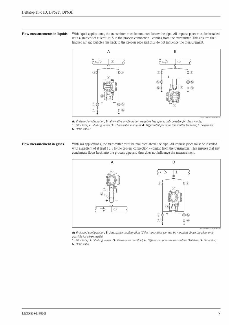
Flow measurements in liquids With liquid applications, the transmitter must be mounted below the pipe. All impulse pipes must be installed
with a gradient of at least 1:15 to the process connection - coming from the transmitter. This ensures that
trapped air and bubbles rise back to the process pipe and thus do not influence the measurement.
P01-DPxxxxxx-11-xx-xx-xx-005
A: Preferred configuration; B: alternative configuration (requires less space; only possible for clean media)
1: Pitot tube; 2: Shut-off valves; 3: Three-valve manifold; 4: Differential pressure transmitter Deltabar; 5: Separator;
6: Drain valves
Flow measurement in gases With gas applications, the transmitter must be mounted above the pipe. All impulse pipes must be installed
with a gradient of at least 15:1 to the process connection - coming from the transmitter. This ensures that any
condensate flows back into the process pipe and thus does not influence the measurement.
P01-DPxxxxxx-11-xx-xx-xx-006
A: Preferred configuration; B: Alternative configuration (if the transmitter can not be mounted above the pipe; only
possible for clean media)
1: Pitot tube; 2: Shut-off valves ; 3: Three-valve manifold; 4: Differential pressure transmitter Deltabar; 5: Separator;
6: Drain valve
+ –
1
2
3
4
5
6
2
5
+ –
1
2
3
5
6
2
4
5
A B
6
6
+ –
1
2
3
4
A
1
3
2
B
4
+ –5
6
5
6
2
Endress+Hauser 9
Deltatop DP61D, DP62D, DP63D
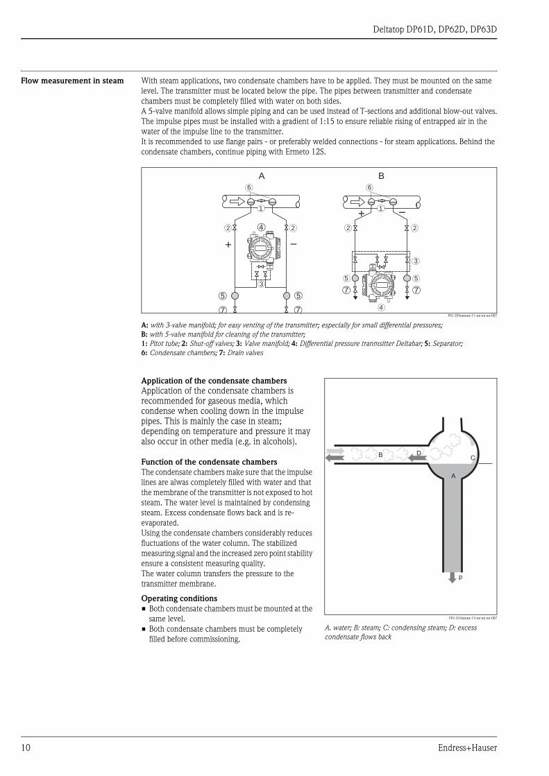
Flow measurement in steam With steam applications, two condensate chambers have to be applied. They must be mounted on the same
level. The transmitter must be located below the pipe. The pipes between transmitter and condensate
chambers must be completely filled with water on both sides.
A 5-valve manifold allows simple piping and can be used instead of T-sections and additional blow-out valves.
The impulse pipes must be installed with a gradient of 1:15 to ensure reliable rising of entrapped air in the
water of the impulse line to the transmitter.
It is recommended to use flange pairs - or preferably welded connections - for steam applications. Behind the
condensate chambers, continue piping with Ermeto 12S.
P01-DPxxxxxx-11-xx-xx-xx-007
A: with 3-valve manifold; for easy venting of the transmitter; especially for small differential pressures;
B: with 5-valve manifold for cleaning of the transmitter;
1: Pitot tube; 2: Shut-off valves; 3: Valve manifold; 4: Differential pressure tranmsitter Deltabar; 5: Separator;
6: Condensate chambers; 7: Drain valves
+ –
4
3
5
6
5
2
1
2➃
+ –
➄
➆
➄
6
1
2 2
3
➆
A B
➆ ➆
Application of the condensate chambers
Application of the condensate chambers is recommended for gaseous media, which condense when cooling down in the impulse pipes. This is mainly the case in steam; depending on temperature and pressure it may also occur in other media (e.g. in alcohols).
Function of the condensate chambers
The condensate chambers make sure that the impulse
lines are alwas completely filled with water and that
the membrane of the transmitter is not exposed to hot
steam. The water level is maintained by condensing
steam. Excess condensate flows back and is re-
evaporated.
Using the condensate chambers considerably reduces
fluctuations of the water column. The stabilized
measuring signal and the increased zero point stability
ensure a consistent measuring quality.
The water column transfers the pressure to the
transmitter membrane.
Operating conditions
• Both condensate chambers must be mounted at the
same level.
• Both condensate chambers must be completely
filled before commissioning.
P01-DOxxxxx-15-xx-xx-xx-007
A. water; B: steam; C: condensing steam; D: excess
condensate flows back
A
B CD
p
10 Endress+Hauser

Deltatop DP61D, DP62D, DP63D
Mounting positions
Versions Compact version
With the compact version of the Deltatop, the Pitot tube, the manifold and the transmitter are delivered readily
mounted. Additional piping and additional valves are not required. Thus, leakage problems are eliminated.
Remote version
With the remote version of the Deltatop, the Pitot tube, the manifolds, the shut-off valves and the transmitter
are delivered separately and must be mounted on-site. This version is recommended:
• for high process temperatures which make a direct mounting of the transmitter impossible.
• if due to shortage of space the transmitter can not be mounted directly at the Pitot tube.
Flow direction • The flow direction is marked by an arrow on the flange plate (compact version) or on the probe head (remote
version).
• "Mounting left" and "Mounting right" refer to the flow direction.
For compact instruments, which are mounted from above or from below, the instrument is shipped in a way
that the transmitter is mounted at the left or right side, respectively (with respect to the flow direction).
For steam versions, which are mounted laterally, the condensate chambers and the transmitter are mounted
on the left or right side, respectively (with respect to the flow direction).
• For compact versions the transmitter is always mounted in a way such that the display can be read in the
specified mounting position and needs not to be rotated.
Gas measurements
compact; vertical1) compact; horizontal2) remote; vertical remote; horizontal
flow upwards
DP6xD-CV...
P01-DP61Dxxx-11-00-00-xx-001
mounting left
DP6xD-CB...
P01-DP61Dxxx-11-00-00-xx-007
upwards/downwards
DP6xD-BW...
P01-DP61Dxxx-11-00-00-xx-013
top/bottom
DP6xD-BD...
P01-DP61Dxxx-11-00-00-xx-016
flow downwards
DP6xD-CU...
P01-DP61Dxxx-11-00-00-xx-002
mounting right
DP6xD-CC...
P01-DP61Dxxx-11-00-00-xx-008
1) recommended housing version for the Deltabar S: T14 (for use of the Deltabar Display)
2) recommended housing version for the Deltabar S: T15 (for use of the Deltabar Display)
Endress+Hauser 11

Deltatop DP61D, DP62D, DP63D
Liquid measurements
compact; vertical1) compact; horizontal2) remote; vertical remote; horizontal
flow upwards
DP6xD-EV...
P01-DP61Dxxx-11-00-00-xx-001
mounting left
DP6xD-EB...
P01-DP61Dxxx-11-00-00-xx-009
upwards/downwards
DP6xD-DW...
P01-DP61Dxxx-11-00-00-xx-014
top/bottom
DP6xD-DD...
P01-DP61Dxxx-11-00-00-xx-017
flow downwards
DP6xD-EU...
P01-DP61Dxxx-11-00-00-xx-002
mounting right
DP6xD-EC...
P01-DP61Dxxx-11-00-00-xx-010
1) recommended housing version for the Deltabar S: T14 (for use of the Deltabar Display)
2) recommended housing version for the Deltabar S: T15 (for use of the Deltabar Display)
12 Endress+Hauser
Deltatop DP61D, DP62D, DP63D
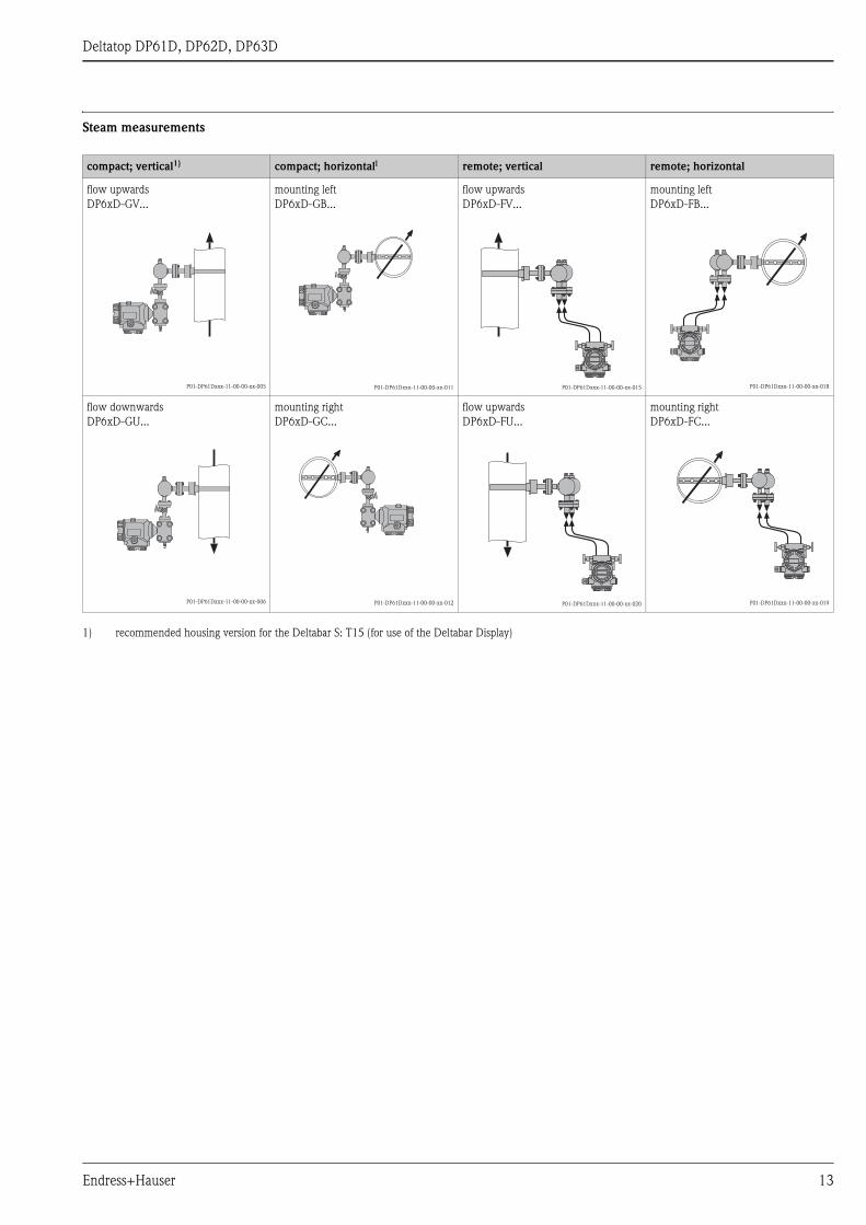
Steam measurements
compact; vertical1) compact; horizontal1 remote; vertical remote; horizontal
flow upwards
DP6xD-GV...
P01-DP61Dxxx-11-00-00-xx-005
mounting left
DP6xD-GB...
P01-DP61Dxxx-11-00-00-xx-011
flow upwards
DP6xD-FV...
P01-DP61Dxxx-11-00-00-xx-015
mounting left
DP6xD-FB...
P01-DP61Dxxx-11-00-00-xx-018
flow downwards
DP6xD-GU...
P01-DP61Dxxx-11-00-00-xx-006
mounting right
DP6xD-GC...
P01-DP61Dxxx-11-00-00-xx-012
flow upwards
DP6xD-FU...
P01-DP61Dxxx-11-00-00-xx-020
mounting right
DP6xD-FC...
P01-DP61Dxxx-11-00-00-xx-019
1) recommended housing version for the Deltabar S: T15 (for use of the Deltabar Display)
Endress+Hauser 13

Deltatop DP61D, DP62D, DP63D
Installation and process conditions
Up- and downstream lengths In order to ensure a homogeneous flow profile it is necessary to mount the Pitot tube in a sufficient distance to
narrowings or bends of the pipe. The required upstream and downstream lengths for different types of obstacles
are summarized in the following table:
Examples (schematic)
P01-DPxxxxxx-11-xx-xx-xx-008
1: upstream length; 2: downstream length;
a: 90° bend; b: valve, open; c: 2x90° bend
! Note!
The requirments concerning the pipe according to ISO5167 have to be met (weld seams, roughness etc).
Homogeneity The fluid must be homogeneous. No changes of the state of aggregation (liquid, gas, steam) may occur.
The pipe must always be completely filled.
Temperature, Pressure
Temperature and pressure may not be subject to large fluctuations.
If required, a temperature and pressure compensation must be applied for gases and steam (see page 6).
Type of obstacle Min. upstream length Min. downstream length
90° bend 7 x D 3 x D
2x90° bend
in the same plane
9 x D 3 x D
2x90° bend
in perpendicular planes
17 x D 4 x D
concentric reducer 7 x D 3 x D
concentric expander 7 x D 3 x D
ball/gate valve, fully open 24 x D 4 x D
D: Inner pipe diameter
1 2
a
b
c
Compact version Remote version
max. temperature • for gases and liquids:
200°C (390 °F)
• for steam:
300 °C (570 °F)
• with standard material:
approx. 500 °C (930 °F)
• with special material:
approx. 1000 °C (1830 °F)
max. pressure 420 bar (6000 psi)
14 Endress+Hauser

Deltatop DP61D, DP62D, DP63D
Reynolds number A turbulent flow is required for differential pressure flow measurement. The Reynolds number Re determines
whether the flow is laminar or turbulent. Re is a non-dimensional parameter which describes the dependency
of the flow on the velocity, the internal diamter of the tube as well as the medium density and viscosity. For a
reliable measurement with Pitot tubes the minimum Reynolds number is Re ≥ 3150.
! Note!
The Reynolds number and the application limits are calculated by the Applicator selection and sizing tool.
Endress+Hauser 15
Deltatop DP61D, DP62D, DP63D
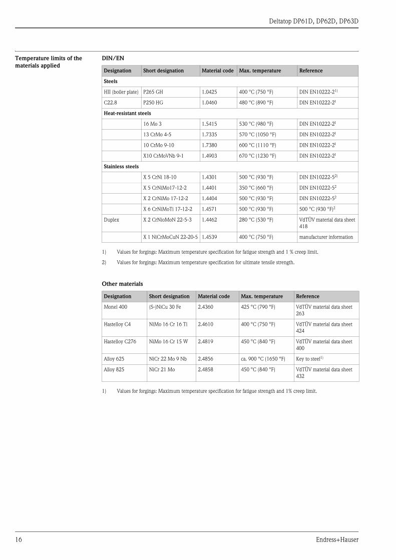
Temperature limits of the
materials applied
DIN/EN
Other materials
Designation Short designation Material code Max. temperature Reference
Steels
HII (boiler plate) P265 GH 1.0425 400 °C (750 °F) DIN EN10222-21)
1) Values for forgings: Maximum temperature specification for fatigue strength and 1 % creep limit.
C22.8 P250 HG 1.0460 480 °C (890 °F) DIN EN10222-21
Heat-resistant steels
16 Mo 3 1.5415 530 °C (980 °F) DIN EN10222-21
13 CrMo 4-5 1.7335 570 °C (1050 °F) DIN EN10222-21
10 CrMo 9-10 1.7380 600 °C (1110 °F) DIN EN10222-21
X10 CrMoVNb 9-1 1.4903 670 °C (1230 °F) DIN EN10222-21
Stainless steels
X 5 CrNi 18-10 1.4301 500 °C (930 °F) DIN EN10222-52)
2) Values for forgings: Maximum temperature specification for ultimate tensile strength.
X 5 CrNiMo17-12-2 1.4401 350 °C (660 °F) DIN EN10222-52
X 2 CrNiMo 17-12-2 1.4404 500 °C (930 °F) DIN EN10222-52
X 6 CrNiMoTi 17-12-2 1.4571 500 °C (930 °F) 500 °C (930 °F)2
Duplex X 2 CrNioMoN 22-5-3 1.4462 280 °C (530 °F) VdTÜV material data sheet
418
X 1 NiCrMoCuN 22-20-5 1.4539 400 °C (750 °F) manufacturer information
Designation Short designation Material code Max. temperature Reference
Monel 400 (S-)NiCu 30 Fe 2.4360 425 °C (790 °F) VdTÜV material data sheet
263
Hastelloy C4 NiMo 16 Cr 16 Ti 2.4610 400 °C (750 °F) VdTÜV material data sheet
424
Hastelloy C276 NiMo 16 Cr 15 W 2.4819 450 °C (840 °F) VdTÜV material data sheet
400
Alloy 625 NiCr 22 Mo 9 Nb 2.4856 ca. 900 °C (1650 °F) Key to steel1)
1) Values for forgings: Maximum temperature specification for fatigue strength and 1% creep limit.
Alloy 825 NiCr 21 Mo 2.4858 450 °C (840 °F) VdTÜV material data sheet
432
16 Endress+Hauser

Deltatop DP61D, DP62D, DP63D
ASME/AISI/ASTM
Plastics
! Note!
All temperature specifications are only guide values. The temperature limits have to be checked in each case.
Depending on the pressure and the medium, they may strongly deviate from these values.
Designation Short designation Material code Max. temperature Reference
Steels
C-Si A105 K03504 425 °C (790 °F) ASME B16.51)
1) Values for flanges: Maximum recommended temperature for permanent use or maximum temperature specification
of the pressure-temperature ratings.
Heat-resistant steels
C-1/2Mo A182 Gr. F1 K12822 465°C (860 °F) ASME B16.51
1 1/4Cr-1/2Mo-Si A 182 Gr. F11 Cl.2 K11572 590 °C (1090 °F) ASME B16.51
2 1/4Cr-1Mo A 182 Gr. F22 Cl.3 K21590 590 °C (1090 °F) ASME B16.51
Stainless steels
18Cr-8Ni A 182 Gr. F304 S30400 538 °C (1000 °F) ASME B16.51
16Cr-12Ni-2Mo A 182 Gr. F316 S31600 538 °C (1000 °F) ASME B16.51
16Cr-12Ni-2Mo A 182 Gr. F316L S31603 450 °C (840 °F) ASME B16.51
22Cr-5Ni-3Mo-N A 182 Gr. F51 S31803 315 °C (600 °F) ASME B16.51
A 182 Gr. F904L N08904 375 °C (700 °F) ASME B16.51
Designation Short designation Max. temperature Reference
PVC polyvinyl chloride up to approx. 70 °C (150 °F) manufacturer specification
PP polypropylene up to approx. 90 °C (190 °F) manufacturer specification
PE polyethylene up to approx. 80 °C (170 °F) manufacturer specification
PVDF polyvinylidene fluoride up to approx. 130 °C (260 °F) manufacturer specification
PTFE polytetrafluorethylene up to approx. 150 °C (300 °F) manufacturer specification
Endress+Hauser 17

Deltatop DP61D, DP62D, DP63D
Pressure-temperature curves
for flanges according to
EN1092-1:2001
PN100 /PN63
P01-DOxxxxxx-05-xx-xx-xx-006
PN40 /PN25
P01-DOxxxxxx-05-xx-xx-xx-005
0
20
40
60
80
100
120
0 50 100 150 200 250 300 350 400 450 500 550T (°C)
P (bar)
C22.8 / PN100
16Mo3 / PN100
316L / PN100
C22.8 / PN63
16Mo3 / PN63
316L / PN63
0
5
10
15
20
25
30
35
40
45
0 50 100 150 200 250 300 350 400 450 500 550T (°C)
P (bar)
C22.8 / PN40
16Mo3 / PN40
316L / PN40
C22.8 / PN25
16Mo3 / PN25
316L / PN25
18 Endress+Hauser

Deltatop DP61D, DP62D, DP63D
PN16 / PN10
P01-DOxxxxxx-05-xx-xx-xx-004
! Note!
The values for 316L refer to the 0,2% yield strength.
0
2
4
6
8
10
12
14
16
18
0 50 100 150 200 250 300 350 400 450 500 550T (°C)
P (bar)
C22.8 / PN16
16Mo3 / PN16
316L / PN16
C22.8 / PN10
16Mo3 / PN10
316L / PN10
Endress+Hauser 19
Deltatop DP61D, DP62D, DP63D
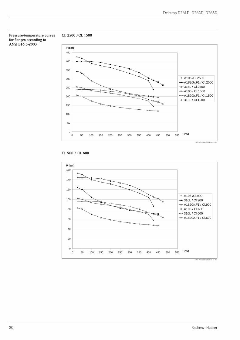
Pressure-temperature curves
for flanges according to
ANSI B16.5-2003
Cl. 2500 /Cl. 1500
P01-DOxxxxxx-05-xx-xx-xx-003
Cl. 900 / Cl. 600
P01-DOxxxxxx-05-xx-xx-xx-002
0
50
100
150
200
250
300
350
400
450
0 50 100 150 200 250 300 350 400 450 500 550T (°C)
P (bar)
A105 /Cl.2500
A182Gr.F1 / Cl.2500
316L / Cl.2500
A105 / Cl.1500
A182Gr.F1 / Cl.1500
316L / Cl.1500
0
20
40
60
80
100
120
140
160
0 50 100 150 200 250 300 350 400 450 500 550T (°C)
P (bar)
A105 /Cl.900
316L / Cl.900
A182Gr.F1 / Cl.900
A105 / Cl.600
316L / Cl.600
A182Gr.F1 / Cl.600
20 Endress+Hauser

Deltatop DP61D, DP62D, DP63D
Cl. 300 /Cl. 150
P01-DOxxxxxx-05-xx-xx-xx-001
! Note!
The values for 316L refer to the 0,2% yield strength.
0
10
20
30
40
50
60
0 50 100 150 200 250 300 350 400 450 500 550T (°C)
P (bar)
A105 /Cl.300
A182Gr.F1 / Cl.300
316L / Cl.300
A105 / Cl.150
A182Gr.F1 / Cl.150
316L / Cl.150
Endress+Hauser 21
Deltatop DP61D, DP62D, DP63D
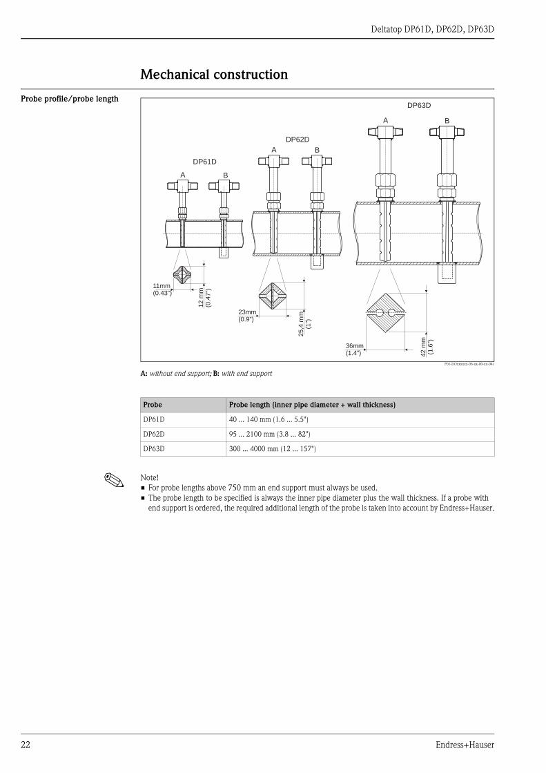
Mechanical construction
Probe profile/probe length
P01-DOxxxxxx-06-xx-00-xx-041
A: without end support; B: with end support
! Note!
• For probe lengths above 750 mm an end support must always be used.
• The probe length to be specified is always the inner pipe diameter plus the wall thickness. If a probe with
end support is ordered, the required additional length of the probe is taken into account by Endress+Hauser.
DP61D
DP62D
DP63D
A
A
A
B
B
B
11mm(0.43”)
12
mm
(0.4
7”)
23mm(0.9”)
25,4
mm
(1”)
36mm(1.4”) 4
2m
m(1
.6”)
Probe Probe length (inner pipe diameter + wall thickness)
DP61D 40 ... 140 mm (1.6 ... 5.5")
DP62D 95 ... 2100 mm (3.8 ... 82")
DP63D 300 ... 4000 mm (12 ... 157")
22 Endress+Hauser

Deltatop DP61D, DP62D, DP63D
Typical configurations
P01-DOxxxxxx-06-xx-00-xx-026b
For steam in horizontal pipes; mounting right
Dimensions in mm (inch)
P01-DOxxxxxx-06-xx-00-xx-024
For liquids and gases in horizontal pipes; with cutting ring
connection
P01-DOxxxxxx-06-xx-00-xx-025
For liquids and gases in vertical pipes; with cutting ring
connection
FIELDTERMINALS
FIELDTERMINALS
+ –
~28
0(~
11
)
~ 200(~ 7.9)
40
(1.5
7)
a = 110 (4.3)b = 40 (1.57)
a
b
~130(~5.1)
127(5)
P01-DOxxxxxx-06-xx-00-xx-027
For steam in vertical pipes
+ –
Endress+Hauser 23

Deltatop DP61D, DP62D, DP63D
Dimensions/weight Dimensions of the compact version
P01-DOxxxxxx-06-xx-00-xx-028
Dimensions of the remote version
P01-DOxxxxxx-06-xx-00-xx-029
H1
H2
WD
H3
H4
H7
H5
H6
1
2
3
D1
D2
SW 1
H1
H2
WD
H3
H4
H7
H5
H6
1 2 3
D1
D2
SW 1
Probe D1
[mm (inch)]
D2
[mm (inch)]
Flange m Cutting ring n End support o
H1
[mm (inch)]
H2
[mm (inch)]
H4
[mm (inch)]
H5
[mm (inch)]
H6
[mm (inch)]
SW1
[mm (inch)]
H7
[mm (inch)]
DP61D 18 (0.71) 12 (0.47) 180 (7.1) 80 (3.1) 130 (5.1) 48 (1.9) 10 (0.39) 27 (1.1) 40 (1.6)
DP62D 35 (1.4) 25 (0.98) 227 (8.9) 127 (5.0) 148 (5.8) 68 (2.7) 15 (0.59) 45 (1.8) 65 (2.6)
DP63D 47 (1.9) 42 (1.7) 150 (5.9) 168 (6.6) 60 (2.4) 15 (0.59) 58 (2.3) 60 (2.4)
24 Endress+Hauser
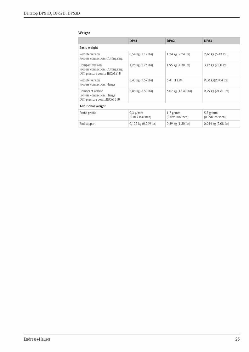
Deltatop DP61D, DP62D, DP63D
Weight
DP61 DP62 DP63
Basic weight
Remote version
Process connection: Cutting ring
0,54 kg (1.19 lbs) 1,24 kg (2.74 lbs) 2,46 kg (5.43 lbs)
Compact version
Process connection: Cutting ring
Diff. pressure conn.: IEC61518
1,25 kg (2.76 lbs) 1,95 kg (4.30 lbs) 3,17 kg (7,00 lbs)
Remote version
Process connection: Flange
3,43 kg (7.57 lbs) 5,41 (11.94) 9,08 kg(20.04 lbs)
Comopact version
Process connection: Flange
Diff. pressure conn.:IEC61518
3,85 kg (8.50 lbs) 6,07 kg (13.40 lbs) 9,79 kg (21,61 lbs)
Additional weight
Probe profile 0,3 g/mm
(0.017 lbs/inch)
1,7 g/mm
(0.095 lbs/inch)
5,7 g/mm
(0.296 lbs/inch)
End support 0,122 kg (0.269 lbs) 0,59 kg (1.30 lbs) 0,944 kg (2.08 lbs)
Endress+Hauser 25
Deltatop DP61D, DP62D, DP63D
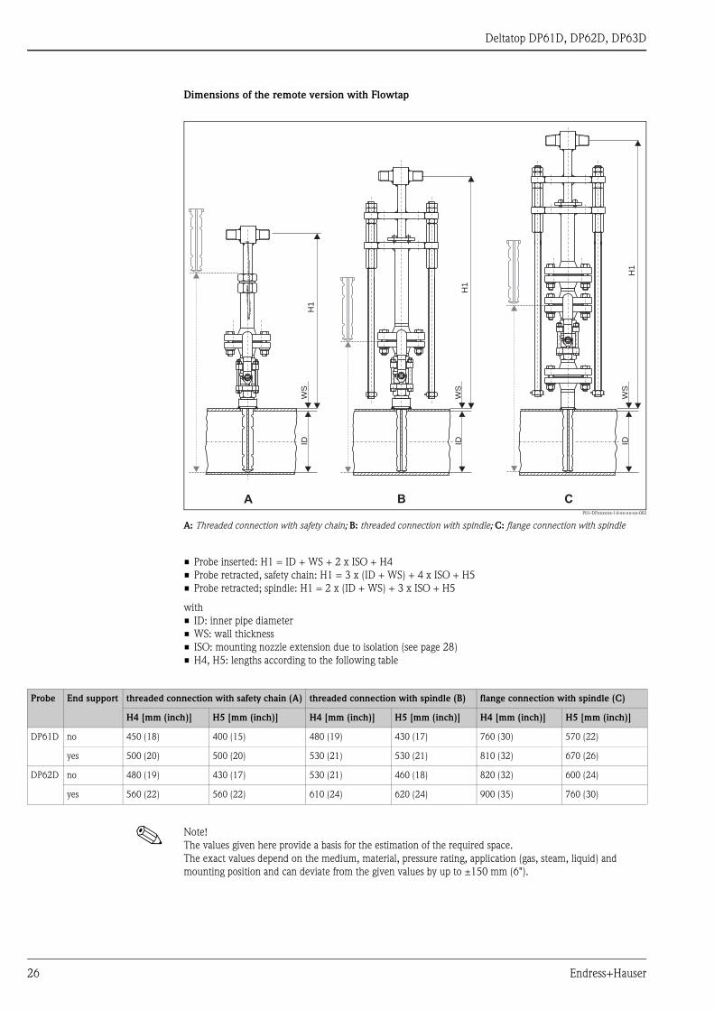
Dimensions of the remote version with Flowtap
P01-DPxxxxxx-14-xx-xx-xx-002
A: Threaded connection with safety chain; B: threaded connection with spindle; C: flange connection with spindle
• Probe inserted: H1 = ID + WS + 2 x ISO + H4
• Probe retracted, safety chain: H1 = 3 x (ID + WS) + 4 x ISO + H5
• Probe retracted; spindle: H1 = 2 x (ID + WS) + 3 x ISO + H5
with
• ID: inner pipe diameter
• WS: wall thickness
• ISO: mounting nozzle extension due to isolation (see page 28)
• H4, H5: lengths according to the following table
! Note!
The values given here provide a basis for the estimation of the required space.
The exact values depend on the medium, material, pressure rating, application (gas, steam, liquid) and
mounting position and can deviate from the given values by up to ±150 mm (6").
A B C
H1
IDW
S
H1
IDW
S
H1
IDW
S
Probe End support threaded connection with safety chain (A) threaded connection with spindle (B) flange connection with spindle (C)
H4 [mm (inch)] H5 [mm (inch)] H4 [mm (inch)] H5 [mm (inch)] H4 [mm (inch)] H5 [mm (inch)]
DP61D no 450 (18) 400 (15) 480 (19) 430 (17) 760 (30) 570 (22)
yes 500 (20) 500 (20) 530 (21) 530 (21) 810 (32) 670 (26)
DP62D no 480 (19) 430 (17) 530 (21) 460 (18) 820 (32) 600 (24)
yes 560 (22) 560 (22) 610 (24) 620 (24) 900 (35) 760 (30)
26 Endress+Hauser

Deltatop DP61D, DP62D, DP63D
Dimensions of the compact version with Flowtap
P01-DPxxxxxx-14-xx-xx-xx-001
A: Threaded connection with safety chain; B: threaded connection with spindle; C: flange connection with spindle
• Probe inserted: H1 = ID + WS + 2 x ISO + H4
• Probe retracted, safety chain: H1 = 3 x (ID + WS) + 4 x ISO + H5
• Probe retracted; spindle: H1 = 2 x (ID + WS) + 3 x ISO + H5
with
• ID: inner pipe diameter
• WS: wall thickness
• ISO: mounting nozzle extension due to isolation (see page 28)
• H4, H5: lengths according to the following table
! Note!
The values given here provide a basis for the estimation of the required space.
The exact values depend on the medium, material, pressure rating, application (gas, steam, liquid) and
mounting position and can deviate from the given values by up to ±150 mm (6").
A B C
H1
IDW
S
H1
IDW
S
Probe End support threaded connection with safety chain (A) threaded connection with spindle (B) flange connection with spindle (C)
H4 [mm (inch)] H5 [mm (inch)] H4 [mm (inch)] H5 [mm (inch)] H4 [mm (inch)] H5 [mm (inch)]
DP61D no 450 (18) 400 (15) 480 (19) 430 (17) 760 (30) 570 (22)
yes 500 (20) 500 (20) 530 (21) 530 (21) 810 (32) 670 (26)
DP62D no 480 (19) 430 (17) 530 (21) 460 (18) 820 (32) 600 (24)
yes 560 (22) 560 (22) 610 (24) 620 (24) 900 (35) 760 (30)
Endress+Hauser 27
Deltatop DP61D, DP62D, DP63D
Process connection, Mounting
nozzle
The features 40 ("Process connection") and 70 ("Mounting nozzle) of the product structure must always be
selected in a suitable combination:
Mounting nozzle extension
End support
Process connection
Mounting nozzle
Pressure rating feature 40
"Process Connection"
feature 70
"Mounting nozzle"
Standard versions
A: Cutting ring PN40 A** A**
B: Flange connectionPN40 ... PN250 (EN) C** C**
Cl.300 ... Cl. 1500 (ANSI) G** G**
Flowtap versions for exchange of the Pitot tube during the ongoing process
C: Flowtap with safety chain PN6 QA* QA*
D: Flowtap with spindlePN16 QD* QD*
PN40 QE* QE*
E: Flowtap with flange and spindle PN63 QL* QL*
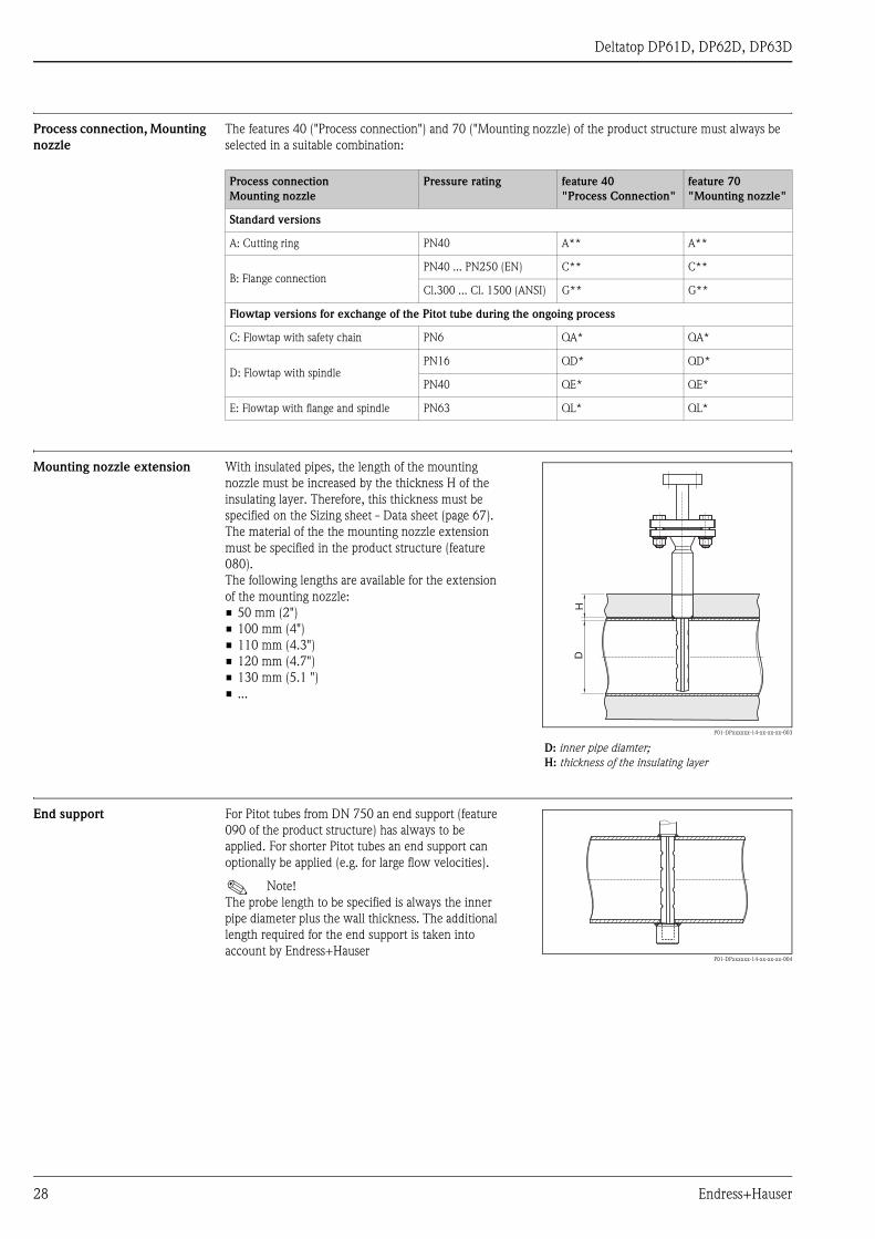
With insulated pipes, the length of the mounting
nozzle must be increased by the thickness H of the
insulating layer. Therefore, this thickness must be
specified on the Sizing sheet - Data sheet (page 67).
The material of the the mounting nozzle extension
must be specified in the product structure (feature
080).
The following lengths are available for the extension
of the mounting nozzle:
• 50 mm (2")
• 100 mm (4")
• 110 mm (4.3")
• 120 mm (4.7")
• 130 mm (5.1 ")
• ...
P01-DPxxxxxx-14-xx-xx-xx-003
D: inner pipe diamter;
H: thickness of the insulating layer
HD
For Pitot tubes from DN 750 an end support (feature
090 of the product structure) has always to be
applied. For shorter Pitot tubes an end support can
optionally be applied (e.g. for large flow velocities).
! Note!
The probe length to be specified is always the inner
pipe diameter plus the wall thickness. The additional
length required for the end support is taken into
account by Endress+HauserP01-DPxxxxxx-14-xx-xx-xx-004
28 Endress+Hauser

Deltatop DP61D, DP62D, DP63D
Differential pressure
connection
Differential pressure connection for the remote version
For the remote version, the following connections are available for the impulse line between the individual
components:
P01-DOxxxxx-15-xx-xx-xx-020
! Note!
The differential pressure connection is selected in feature 100 of the product structure.
No. Outlet
(from the primary
element)
Inlet
(to the accessory)
Application/Remarks
1 welding connection
14/21,3/24 mm
welding connection
14/21,3/24 mm
for highly demanding applications; permanent joint
2 G½ DIN 19207 G½ DIN 19207 + 2 flanges1)
1) The flanges are included in the scope of delivery of the accessory.
detachable; especially suited for steam
3 MNPT½ FNPT½ simple mounting; not suited for steam
4 pipe 12 mm Cutting ring (Ermeto 12S) simple mounting; easily disconnectable; not suited
for steam
5 flange DN15 flange DN15 disconnectable joint; especially suited for steam
1
2
3
4
5
Endress+Hauser 29

Deltatop DP61D, DP62D, DP63D
Differential pressure connection for the compact version (IEC61518)
P01-DOxxxxx-15-xx-xx-xx-014
Standard connection for differential pressure transmitter (oval flanges or flange plate); dimensions in mm (inch)
P01-DPxxxxxx-14-xx-xx-xx-005
Cranked version (for humid gas); dimensions in mm (inch)
41.3
(1.6
)
74 (2.9)
75
(3)
50
(2)
75 (3)
30 Endress+Hauser
Deltatop DP61D, DP62D, DP63D
Integrated temperature sensor
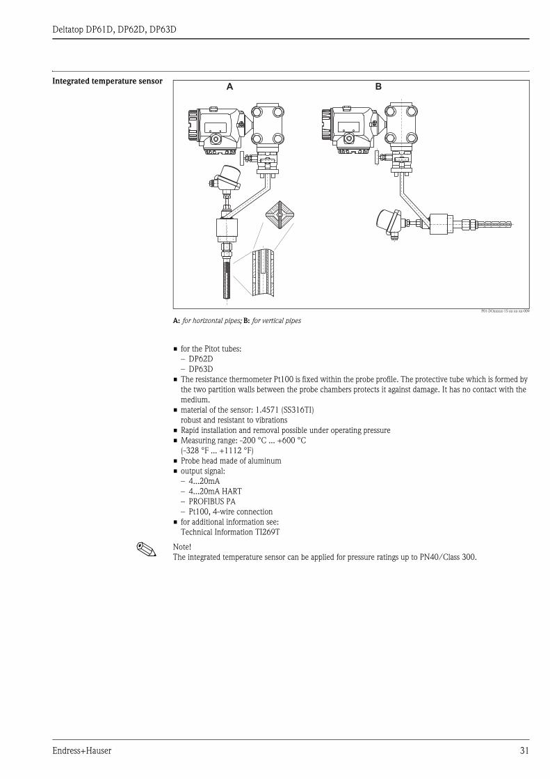
P01-DOxxxxx-15-xx-xx-xx-009
A: for horizontal pipes; B: for vertical pipes
• for the Pitot tubes:
– DP62D
– DP63D
• The resistance thermometer Pt100 is fixed within the probe profile. The protective tube which is formed by
the two partition walls between the probe chambers protects it against damage. It has no contact with the
medium.
• material of the sensor: 1.4571 (SS316TI)
robust and resistant to vibrations
• Rapid installation and removal possible under operating pressure
• Measuring range: -200 °C ... +600 °C
(-328 °F ... +1112 °F)
• Probe head made of aluminum
• output signal:
– 4...20mA
– 4...20mA HART
– PROFIBUS PA
– Pt100, 4-wire connection
• for additional information see:
Technical Information TI269T
! Note!
The integrated temperature sensor can be applied for pressure ratings up to PN40/Class 300.
A B
Endress+Hauser 31

Deltatop DP61D, DP62D, DP63D
Overview of the product structures
Feature Name Description valid for
DP
61
D
DP
62
D
DP
63
D
Primary element
10 Application; Version • Application: "Gas", "Liquid" oder "Steam"
• Version: "remote" oder "compact"
See chapter "Mounting positions" (page 11).
x x x
20 Pipe; Orientation • Pipe: "Horizontal", "Vertical"
• Orientation:
– "left", "right", "top/bottom" for horizontal pipes
– "upwards", "downwards", "upwards/downwards" for vertical pipes
See chapter mounting positions (page 11).
x x x
40 Process Connection Defines the size, type and material of the process connection:
• cutting ring (see page 24)
• flange (see page 24)
• flowtap (see pages 26/27)
For the temperature limits of the materials see page 16.
x x x
60 Probe Length Defines the length of the prob in mm. The probe length is the sum of the inner pipe
diameter plus the wall thickness of the pipe.
For Flowtap versions it must also be specified if the pressure rating is above PN 6
x x x
70 Mounting Nozzle Defines the type, size, pressure rating and material of the mounting nozzle.
The selection must match the selected process connection (feature 40).
For the temperature limits of the materials see page 16.
x x x
80 Extension Mounting Nozzle Defines the length and material of the mounting nozzle extension.
The extension of the mounting nozzle is required for insulated pipes (see page 28).
Possible lengths: 50 mm, 100 mm, 110 mm, 120 mm, 130 mm, ...
! Note!
The selected material must match the selection in feature 70 "mounting nozzle".
! Note!
"Not selected" means that no mounting nozzle extension is required (= 0 mm).
x x x
90 End Support Defines the material of the end support (see page 28).
! Note!
"Not selected" means that the order does not contain an end support.
x x x
100 Diff Pressure Connection; Seal Defines:
• the type of differential pressure connection (see page 29).
• the material of the seal at the differential pressure connection
x x x
110 Temperature sensor Pt100 Defines the type and communication interface of the integrated Pt 100 temperature
sensor (4-wire connection, 4-20 mA analog signal, HART, PROFIBUS PA).
For details see page 31.
! Note!
"Not selected" means that no temperature sensor is integrated.
x x
32 Endress+Hauser

Deltatop DP61D, DP62D, DP63D
Feature Name Description valid for
DP
61
D
DP
62
D
DP
63
D
Accessory: Condensate Chambers
200 2x Condens. Chamber Mat.;
Volume; PN
Defines:
• the material of the condensate chambers
• the volume of the condensate chambers
• the pressure rating of the condensate chambers
For details see page 52.
! Note!
If "not selected" is chosen, no condensate chambers are included in the order. In this
case "not needed" has to be selected in the features 210 to 230.
x x x
210 Filling Cap Condens. Chamber Defines the type of filling cap (see page 52). x x x
220 Inlet Defines the inlet (from the process) of the condensate chamber (see page 29). x x x
230 Outlet Defines the outlet of the condensate chamber (see page 29). x x x
Accessory: Shut-off valve
250 2 x Shut-Off Valve; Gasket Defines:
• the type of shut-off valve
• the material of the gasket
For details see page 48.
! Note!
If "not selected" is chosen, no shut-off valves are included in the order. In this case "not
needed" has to be selected in the features 260 to 280.
x x x
260 Material Shut-Off Valve Defines the material of the shut-off valve.
For the temperature limits of the materials see page 16.
x x x
270 Inlet Shut-Off Valve Defines the inlet (from the process) of the shut-off valve (see page 29). x x x
280 Outlet Shut-Off Valve Defines the outlet of the shut-off valve (see page 29). x x x
Accessory: Manifold
300 Manifold Version Defines the manifold version (see page 54 ff.)
! Note!
If "not selected" is chosen, no manifold is included in the order. In this case "not
needed" has to be selected in the features 310 to 330.
x x x
310 Gasket Manifold Defines the material of the gasket of the manifold.
For the temperature limits of the materials see page 16.
x x x
320 Process Connection Manifold Defines the process connection of the manifold (see page 29). x x x
330 Seal Manifold, Screws Defines:
• The material of the seal between the manifold and the transmitter
• The size of the manifold screws
For the temperature limits of the materials see page 16.
" Caution!
The manifold screws must be selected in accordance with the Deltabar differential
pressure transmitter.
x x x
Differential pressure transmitter
450 DP-Transmitter Deltabar Defines if a Deltabar differentail pressure transmitter is included in the order. x x x
Additional options
500 Add. Option Orifice These features are used to define additional characteristics of the respective
components (e.g. material inspection certificates).
The features are optional, which means:
• It is not necessary to select an option in these features.
• Multiple options can be selected in these features.
x x x
520 Add. Option Condens. Chamber x x x
530 Add. Option Shut-Off Valve x x x
540 Add. Option Manifold x x x
550 Add. Option General x x x
Endress+Hauser 33

Deltatop DP61D, DP62D, DP63D
Ordering information
Product structure
Deltatop DP61D10 Application; Version
B Gas; remote
C Gas; compact
D Liquid; remote
E Liquid; compact
F Steam; remote
G Steam; compact
Y special version, to be specified
20 Pipe; Orientation
B Horizontal; left
C Horizontal; right
D Horizontal; top/bottom
V Vertical; upwards
U Vertical; downwards
W Vertical; upwards/downwards
Y special version, to be specified
40 Process connection
Cutting ring
ABB pipe > cutting ring, PN40, 316Ti
EN flanges
CEB DN25 PN40 B1, 316Ti
CGB DN25 PN100 B2, 316Ti
CHB DN25 PN160 E, 316Ti
CJB DN25 PN250 E, 316Tii
ANSI flanges
GBB 1" Cl.300 RF, 316Ti
GCB 1" Cl.600 RF, 316Ti
GEB 1" Cl.1500 RF, 316Ti
GJB 1" Cl.600 RTJ, 316Ti
GLB 1" Cl.1500 RTJ, 316Ti
Flowtap
QAB Flowtap PN6, 316Ti + safety chain
QDB Flowtap PN16, 316Ti + spindle
QEB Flowtap PN40, 316Ti + spindle
QLB Flowtap PN63, 316Ti + flange + spindle
Y99 special version, to be specified
60 Probe length (Pipe ID + Wall thickness)
A2 mm 316Ti
D2 mm 316Ti, Flowtap PN6
G2 mm 316Ti, Flowtap >PN6
Y9 special version, to be specified
70 Mounting Nozzle
Cutting ring
AAA cutting ring, PN40, steel
AAB cutting ring, PN40, 316Ti
EN flanges
CEA DN25 PN40 B1, steel
CEB DN25 PN40 B1, 316Ti
CGA DN25 PN100 B2, steel
CGB DN25 PN100 B2, 316Ti
CGF DN25 PN100 B2, 16Mo3
CHA DN25 PN160 E, steel
CHB DN25 PN160 E, 316Ti
CHF DN25 PN160 E, 16Mo3
CJA DN25 PN250 E, steel
CJB DN25 PN250 E, 316Ti
CJF DN25 PN250 E, 16Mo3
ANSI flanges
GBA 1" Cl.300 RF, steel
GBB 1" Cl.300 RF, 316Ti
GBF 1" Cl.300 RF, 16Mo3
GCA 1" Cl.600 RF, steel
GCB 1" Cl.600 RF, 316Ti
GCF 1" Cl.600 RF, 16Mo3
34 Endress+Hauser

Deltatop DP61D, DP62D, DP63D
GEA 1" Cl.1500 RF, steel
GEB 1" Cl.1500 RF, 316Ti
GEF 1" Cl.1500 RF, 16Mo3
GJA 1" Cl.600 RTJ, steel
GJB 1" Cl.600 RTJ, 316Ti
GJF 1" Cl.600 RTJ, 16Mo3
GLA 1" Cl.1500 RTJ, steel
GLB 1" Cl.1500 RTJ, 316Ti
GLF 1" Cl.1500 RTJ, 16Mo3
Flowtap
QAA Flowtap PN6, steel + safety chain
QAB Flowtap PN6, 316Ti + safety chain
QDA Flowtap PN16, steel + spindle
QDB Flowtap PN16, 316Ti + spindle
QEA Flowtap PN40, steel + spindle
QEB Flowtap PN40, 316Ti + spindle
QLA Flowtap PN63, steel + flange + spindle
QLB Flowtap PN63, 316Ti + flange + spindle
Miscellaneous
XAX not selected
Y99 special version, to be specified
80 Extension Mounting Nozzle
A mm, carbon steel
B mm, 316Ti
C mm, 16Mo3
1 not selected
9 special version, to be specified
90 End Support
A Carbon steel
B 316Ti
C 16Mo3
1 not selected
2 Prepared for end support
9 special version, to be specified
100 Diff. Pressure Connection; Seal
B IEC61518; PTFE
C IEC61518; FKM
D IEC61518 cranked, humid gas; PTFE
E IEC61518 cranked, humid gas; FKM
H Tap, MNPT1/2; w/o
K Tap, pipe 12mm; w/o
N Tap, welding conn. 21,3mm; w/o
T Tap, G1/2 DIN19207; w/o
U Flange DN15; w/o
Y special version, to be specified
200 2x Condens. Chamber Mat.; Volume; PN
1 not selected
2 HII (265 GH); 300cm3; PN100
4 316Ti; 300cm3; PN100
9 special version, to be specified
210 Filling Cap Condens. Chamber
A not needed
B NPT1/2
Y special version, to be specified
220 Input Condens. Chamber
A not needed
D Flange DN15
E Welding conn. 21,3mm
V G1/2 DIN19207 steel + 2x flange
W G1/2 DIN19207 stainl. steel + 2x flange
Y special version, to be specified
230 Output Condens. Chamber
A not needed
E Welding conn. 21,3mm
70 Mounting Nozzle
Endress+Hauser 35

Deltatop DP61D, DP62D, DP63D
N Tap, G1/2 DIN19207
T MNPT1/2
Y special version, to be specified
250 2x Shut-Off Valve
1 not selected
5 Ball valve
6 Valve
7 Gate valve
9 special version, to be specified
260 Material Shut-Off Valve
A not needed
B Steel
D 316Ti
E 316
F 316L
Y special version, to be specified
270 Input Shut-Off Valve
A not needed
B Cutting ring (Ermeto 12S)
C FNPT 1/2
E Welding conn. 21,3mm
V G1/2 DIN19207 steel + 2x flange
W G1/2 DIN19207 stainl. steel + 2x flange
Y special version, to be specified
280 Output Shut-Off Valve
A not needed
B Cutting ring (Ermeto 12S)
C FNPT1/2
L Welding conn. 14mm
Y special version, to be specified
300 Manifold Version
111 not selected
AA1 3 valve, steel, forging
AA2 3 valve, 316Ti, forging
AB1 3 valve, steel, milled
AB2 3 valve, 316L, milled
BB1 5 valve, steel, milled, vent
BB2 5 valve, 316L, milled, vent
CA1 5 valve, steel, forging, purge valve
CA2 5 valve, 316Ti, forging, purge valve
DA2 5 valve HT, 316Ti, forging, purge valve
KA2 3 valve, 316Ti, forging, IEC61518, both side
LA2 5 valve, 316Ti, forging, IEC61518 both side, vent
YY9 special version, to be specified
310 Gasket Manifold
A not needed
B PTFE, 200 °C
Y special version, to be specified
320 Process Connection Manifold
A not needed
B FNPT1/2
C Cutting ring (Ermeto 12S)
D Welding conn. 14mm
E IEC61518
Y special version, to be specified
330 Seal Manifold; Screws
A not needed
B PTFE; UNF7/16, max PN420
C PTFE; M10, max PN160
D Viton; UNF7/16, max PN420
E Viton; M10, max PN160
F Viton; M12, max PN420
Y special version, to be specified
230 Output Condens. Chamber
36 Endress+Hauser
Deltatop DP61D, DP62D, DP63D
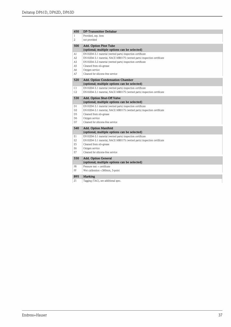
450 DP-Transmitter Deltabar
1 Provided, sep. item
2 not provided
500 Add. Option Pitot Tube
(optional; multiple options can be selected)
A1 EN10204-3.1 material (wetted parts) inspection certificate
A2 EN10204-3.1 material, NACE MR0175 (wetted parts) inspection certificate
A3 EN10204-3.2 material (wetted parts) inspection certificate
A5 Cleaned from oil+grease
A6 Oxygen service
A7 Cleaned for silicone-free service
520 Add. Option Condensation Chamber
(optional; multiple options can be selected)
C1 EN10204-3.1 material (wetted parts) inspection certificate
C2 EN10204-3.1 material, NACE MR0175 (wetted parts) inspection certificate
530 Add. Option Shut-Off Valve
(optional; multiple options can be selected)
D1 EN10204-3.1 material (wetted parts) inspection certificate
D2 EN10204-3.1 material, NACE MR0175 (wetted parts) inspection certificate
D5 Cleaned from oil+grease
D6 Oxygen service
D7 Cleaned for silicone-free service
540 Add. Option Manifold
(optional; multiple options can be selected)
E1 EN10204-3.1 material (wetted parts) inspection certificate
E2 EN10204-3.1 material, NACE MR0175 (wetted parts) inspection certificate
E5 Cleaned from oil+grease
E6 Oxygen service
E7 Cleaned for silicone-free service
550 Add. Option General
(optional; multiple options can be selected)
F8 Pressure test + certificate
FF Wet calibration <300mm, 3-point
895 Marking
Z1 Tagging (TAG), see additional spec.
Endress+Hauser 37

Deltatop DP61D, DP62D, DP63D
Product structure
Deltatop DP62D10 Application; Version
B Gas; remote
C Gas; compact
D Liquid; remote
E Liquid; compact
F Steam; remote
G Steam; compact
Y special version, to be specified
20 Pipe; Orientation
B Horizontal; left
C Horizontal; right
D Horizontal; top/bottom
V Vertical; upwards
U Vertical; downwards
W Vertical; upwards/downwards
Y special version, to be specified
40 Process Connection
Cutting ring
ABB Pipe > cutting ring, PN40, 316Ti
EN flanges
CPB DN32 PN40 B1, 316Ti
DGB DN40 PN100 B2, 316Ti
DGF DN40 PN100 B2, 16Mo3
DHB DN40 PN160 E, 316Ti
DHF DN40 PN160 E, 16Mo3
DJB DN40 PN250 E, 316Ti
DJF DN40 PN250 E, 16Mo3
ANSI flanges
GPB 1-1/2" Cl.300 RF, 316Ti
GQB 1-1/2" Cl.600 RF, 316Ti
GQF 1-1/2" Cl.600 RF, 16Mo3
GSB 1-1/2" Cl.1500 RF, 316Ti
GSF 1-1/2" Cl.1500 RF, 16Mo3
GWB 1-1/2" Cl.600 RTJ, 316Ti
GWF 1-1/2" Cl.600 RTJ, 16Mo3
G0B 1-1/2" Cl.1500 RTJ, 316Ti
G0F 1-1/2" Cl.1500 RTJ, 16Mo3
Flowtap
QAB Flowtap PN6, 316Ti + safety chain
QDB Flowtap PN16, 316Ti + spindle
QEB Flowtap PN40, 316Ti + spindle
QLB Flowtap PN63, 316Ti + flange + spindle
Y99 special version, to be specified
60 Probe Length (Pipe ID + Wall Thickness)
B2 mm, 316Ti, w/o end support
C2 mm, 316Ti, end support
C3 mm, 16Mo3, end support
E2 mm 316Ti, Flowtap PN6 w/o end support
F2 mm 316Ti, Flowtap PN6 + end support
H2 mm 316Ti, Flowtap >PN6 w/o end support
K2 mm 316Ti, Flowtap >PN6 + end support
Y9 special version, to be specified
70 Mounting Nozzle
Cutting ring
AAA cutting ring, PN40, steel
AAB cutting ring, PN40, 316Ti
EN flanges
CPA DN32 PN40 B1, steel
CPB DN32 PN40 B1, 316Ti
CPF DN32 PN40 B1, 16Mo3
DGA DN40 PN100 B2, steel
DGB DN40 PN100 B2, 316Ti
DGF DN40 PN100 B2, 16Mo3
DHA DN40 PN160 E, steel
DHB DN40 PN160 E, 316Ti
DHF DN40 PN160 E, 16Mo3
38 Endress+Hauser
Deltatop DP61D, DP62D, DP63D
DJA DN40 PN250 E, steel
DJB DN40 PN250 E, 316Ti
DJF DN40 PN250 E, 16Mo3
ANSI flanges
GPA 1-1/2" Cl.300 RF, steel
GPB 1-1/2" Cl.300 RF, 316Ti
GPF 1-1/2" Cl.300 RF, 16Mo3
GQA 1-1/2" Cl.600 RF, steel
GQB 1-1/2" Cl.600 RF, 316Ti
GQF 1-1/2" Cl.600 RF, 16Mo3
GSA 1-1/2" Cl.1500 RF, steel
GSB 1-1/2" Cl.1500 RF, 316Ti
GSF 1-1/2" Cl.1500 RF, 16Mo3
GWA 1-1/2" Cl.600 RTJ, steel
GWB 1-1/2" Cl.600 RTJ, 316Ti
GWF 1-1/2" Cl.600 RTJ, 16Mo3
G0A 1-1/2" Cl.1500 RTJ, steel
G0B 1-1/2" Cl.1500 RTJ, 316Ti
G0F 1-1/2" Cl.1500 RTJ, 16Mo3
Flowtap
QAA Flowtap PN6, steel + safety chain
QAB Flowtap PN6, 316Ti + safety chain
QDA Flowtap PN16, steel + spindle
QDB Flowtap PN16, 316Ti + spindle
QEA Flowtap PN40, steel + spindle
QEB Flowtap PN40, 316Ti + spindle
QLA Flowtap PN63, steel + flange + spindle
QLB Flowtap PN63, 316Ti + flange + spindle
Miscellaneous
XAX not selected
Y99 special version, to be specified
80 Extension Mounting Nozzle
A mm, carbon steel
B mm, 316Ti
C mm, 16Mo3
1 not selected
9 special version, to be specified
90 End Support
A carbon steel
B 316Ti
C 16Mo3
1 not selected
2 prepared for end support
9 special version, to be specified
100 Diff. Pressure Connection; Seal
B IEC61518; PTFE
C IEC61518; FKM
D IEC61518 cranked, humid gas; PTFE
E IEC61518 cranked, humid gas; FKM
H tap, MNPT1/2; w/o
K tap, pipe 12mm; w/o
N tap, welding conn. 21,3mm; w/o
P tap, welding conn. 24mm; w/o
T tap, G1/2 DIN19207; w/o
U flange DN15; w/o
Y special version, to be specified
110 Temperature Sensor Pt100
A not selected
B 4-20mA, max 600°C
C 4-20mA HART, max 600°C
D PROFIBUS PA, max 600°C
E Terminal Block 4-wire, max 600°C
Y special version, to be specified
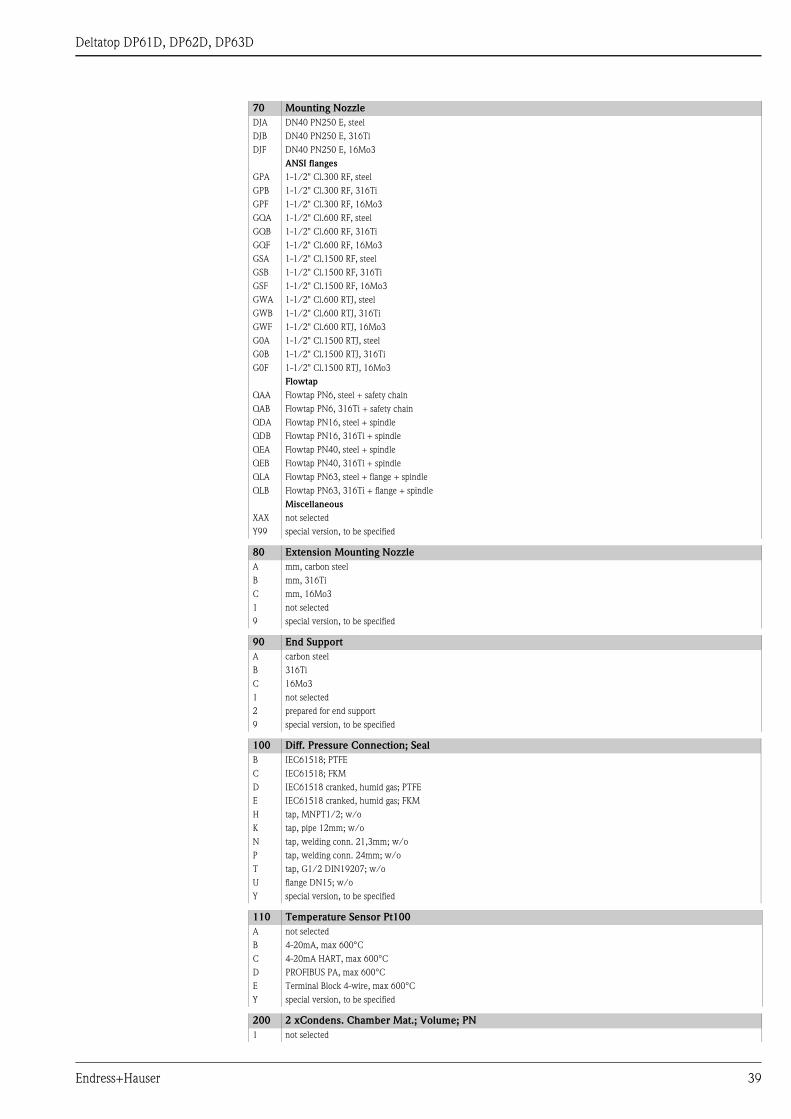
200 2 xCondens. Chamber Mat.; Volume; PN
1 not selected
70 Mounting Nozzle
Endress+Hauser 39

Deltatop DP61D, DP62D, DP63D
2 HII (265 GH); 300cm3; PN100
4 316Ti; 300cm3; PN100
6 16Mo3; 300cm3; PN100
7 16Mo3; 20cm3; PN250
9 special version, to be specified
210 Filling Cap Condens. Chamber
A not needed
B NPT1/2
Y special version, to be specified
220 Input Condens. Chamber
A not needed
D Flange DN15
E Wwelding conn. 21,3mm
G Welding conn. 24mm
V G1/2 DIN19207 steel + 2x flange
W G1/2 DIN19207 stainl. steel + 2x flange
Y special version, to be specified
230 Output Condens. Chamber
A not needed
E Welding conn. 21,3mm
G Welding conn. 24mm
N Tap, G1/2 DIN19207
T MNPT1/2
Y special version, to be specified
250 2x Shut-Off Valve
1 not selected
5 Ball valve
6 Valve
7 Gate valve
9 special version, to be specified
260 Material Shut-Off Valve
A not needed
B Steel
D 316Ti
G 16Mo3
E 316
F 316L
Y special version, to be specified
270 Input Shut-Off Valve
A not needed
B Cutting ring (Ermeto 12S)
C FNPT 1/2
E Welding conn. 21,3mm
G Welding conn. 24mm
V G1/2 DIN19207 steel + 2x flange
W G1/2 DIN19207 stainl. steel + 2x flange
Y special version, to be specified
280 Output Shut-Off Valve
A not needed
B Cutting ring (Ermeto 12S)
C FNPT1/2
L welding conn. 14mm
Y special version, to be specified
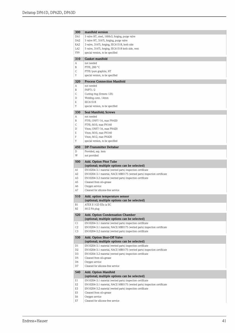
300 manifold version
111 not selected
AA1 3 valve, steel, forging
AA2 3 valve, 316Ti, forging
AB1 3 valve, steel, milled
AB2 3 valve, 316L, milled
BB1 5 valve, steel, milled, vent
BB2 5 valve, 316L, milled, vent
CA1 5 valve, steel, forging, purge valve
CA2 5 valve, 316Ti, forging, purge valve
200 2 xCondens. Chamber Mat.; Volume; PN
40 Endress+Hauser
Deltatop DP61D, DP62D, DP63D
DA1 5 valve HT, steel, 16Mo3, forging, purge valve
DA2 5 valve HT, 316Ti, forging, purge valve
KA2 3 valve, 316Ti, forging, IEC61518, both side
LA2 5 valve, 316Ti, forging, IEC61518 both side, vent
YY9 special version, to be specified
310 Gasket manifold
A not needed
B PTFE, 200 °C
C PTFE/pure graphite, HT
Y special version, to be specified
320 Process Connection Manifold
A not needed
B FNPT1/2
C Cutting ring (Ermeto 12S)
D Welding conn. 14mm
E IEC61518
Y special version, to be specified
330 Seal Manifold; Screws
A not needed
B PTFE; UNF7/16, max PN420
C PTFE; M10, max PN160
D Viton; UNF7/16, max PN420
E Viton; M10, max PN160
F Viton; M12, max PN420
Y special version, to be specified
450 DP-Transmitter Deltabar
D Provided, sep. item
W not provided
500 Add. Option Pitot Tube
(optional; multiple options can be selected)
A1 EN10204-3.1 material (wetted parts) inspection certificate
A2 EN10204-3.1 material, NACE MR0175 (wetted parts) inspection certificate
A3 EN10204-3.2 material (wetted parts) inspection certificate
A5 Cleaned from oil+grease
A6 Oxygen service
A7 Cleaned for silicone-free service
510 Add. option temperature sensor
(optional; multiple options can be selected)
B1 ATEX II 1GD EEx ia IIC
B2 M12 PA plug
520 Add. Option Condensation Chamber
(optional; multiple options can be selected)
C1 EN10204-3.1 material (wetted parts) inspection certificate
C2 EN10204-3.1 material, NACE MR0175 (wetted parts) inspection certificate
C3 EN10204-3.2 material (wetted parts) inspection certificate
530 Add. Option Shut-Off Valve
(optional; multiple options can be selected)
D1 EN10204-3.1 material (wetted parts) inspection certificate
D2 EN10204-3.1 material, NACE MR0175 (wetted parts) inspection certificate
D3 EN10204-3.2 material (wetted parts) inspection certificate
D5 Cleaned from oil+grease
D6 Oxygen service
D7 Cleaned for silicone-free service
540 Add. Option Manifold
(optional; multiple options can be selected)
E1 EN10204-3.1 material (wetted parts) inspection certificate
E2 EN10204-3.1 material, NACE MR0175 (wetted parts) inspection certificate
E3 EN10204-3.2 material (wetted parts) inspection certificate
E5 Cleaned from oil+grease
E6 Oxygen service
E7 Cleaned for silicone-free service
300 manifold version
Endress+Hauser 41

Deltatop DP61D, DP62D, DP63D
550 Add. Option General
(optional; multiple options can be selected)
F8 Pressure test + certificate
FF Wet calibration <300mm, 3-point
895 Marking
Z1 Tagging (TAG), see additional spec.
42 Endress+Hauser
Deltatop DP61D, DP62D, DP63D
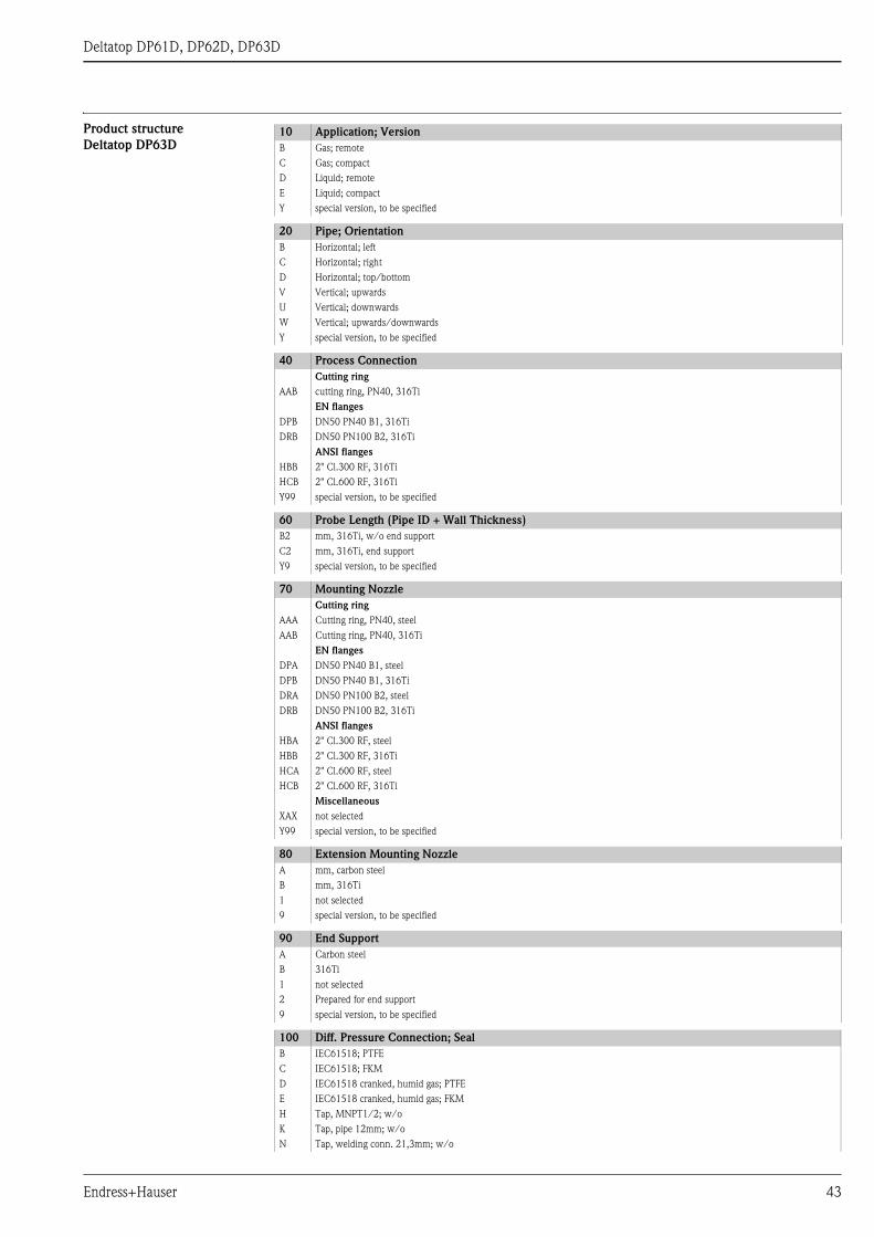
Product structure
Deltatop DP63D10 Application; Version
B Gas; remote
C Gas; compact
D Liquid; remote
E Liquid; compact
Y special version, to be specified
20 Pipe; Orientation
B Horizontal; left
C Horizontal; right
D Horizontal; top/bottom
V Vertical; upwards
U Vertical; downwards
W Vertical; upwards/downwards
Y special version, to be specified
40 Process Connection
Cutting ring
AAB cutting ring, PN40, 316Ti
EN flanges
DPB DN50 PN40 B1, 316Ti
DRB DN50 PN100 B2, 316Ti
ANSI flanges
HBB 2" Cl.300 RF, 316Ti
HCB 2" Cl.600 RF, 316Ti
Y99 special version, to be specified
60 Probe Length (Pipe ID + Wall Thickness)
B2 mm, 316Ti, w/o end support
C2 mm, 316Ti, end support
Y9 special version, to be specified
70 Mounting Nozzle
Cutting ring
AAA Cutting ring, PN40, steel
AAB Cutting ring, PN40, 316Ti
EN flanges
DPA DN50 PN40 B1, steel
DPB DN50 PN40 B1, 316Ti
DRA DN50 PN100 B2, steel
DRB DN50 PN100 B2, 316Ti
ANSI flanges
HBA 2" Cl.300 RF, steel
HBB 2" Cl.300 RF, 316Ti
HCA 2" Cl.600 RF, steel
HCB 2" Cl.600 RF, 316Ti
Miscellaneous
XAX not selected
Y99 special version, to be specified
80 Extension Mounting Nozzle
A mm, carbon steel
B mm, 316Ti
1 not selected
9 special version, to be specified
90 End Support
A Carbon steel
B 316Ti
1 not selected
2 Prepared for end support
9 special version, to be specified
100 Diff. Pressure Connection; Seal
B IEC61518; PTFE
C IEC61518; FKM
D IEC61518 cranked, humid gas; PTFE
E IEC61518 cranked, humid gas; FKM
H Tap, MNPT1/2; w/o
K Tap, pipe 12mm; w/o
N Tap, welding conn. 21,3mm; w/o
Endress+Hauser 43

Deltatop DP61D, DP62D, DP63D
T Tap, G1/2 DIN19207; w/o
U Flange DN15; w/o
Y special version, to be specified
110 Temperature Sensor Pt100
A not selected
B 4-20mA, max 600°C
C 4-20mA HART, max 600°C
D PROFIBUS PA, max 600°C
E Terminal Block 4-wire, max 600°C
Y special version, to be specified
200 Condens. Chamber Mat.; Volume; PN
1 not selected
2 HII (265 GH); 300cm3; PN100
4 316Ti; 300cm3; PN100
9 special version, to be specified
210 Filling Cap Condens. Chamber
A not needed
B NPT1/2
Y special version, to be specified
220 Input Condens. Chamber
A not needed
D Flange DN15
E Welding conn. 21,3mm
V G1/2 DIN19207 steel + 2x flange
W G1/2 DIN19207 stainl. steel + 2x flange
Y special version, to be specified
230 Output Condens. Chamber
A not needed
E Welding conn. 21,3mm
N Tap, G1/2 DIN19207
T MNPT1/2
Y special version, to be specified
250 2x Shut-Off Valve
1 not selected
5 Ball valve
6 Valve
7 Gate valve
9 special version, to be specified
260 Material Shut-Off Valve
A not needed
B Steel
D 316Ti
E 316
F 316L
Y special version, to be specified
270 Input Shut-Off Valve
A not needed
B Cutting ring (Ermeto 12S)
C FNPT 1/2
E Welding conn. 21,3mm
V G1/2 DIN19207 steel + 2x flange
W G1/2 DIN19207 stainl. steel + 2x flange
Y special version, to be specified
280 Output Shut-Off Valve
A not needed
B Cutting ring (Ermeto 12S)
C FNPT1/2
L Welding conn. 14mm
Y special version, to be specified
300 Manifold Version
111 not selected
AA1 3 valve, steel, forging
100 Diff. Pressure Connection; Seal
44 Endress+Hauser

Deltatop DP61D, DP62D, DP63D
AA2 3 valve, 316Ti, forging
AB1 3 valve, steel, milled
AB2 3 valve, 316L, milled
BB1 5 valve, steel, milled, vent
BB2 5 valve, 316L, milled, vent
CA1 5 valve, steel, forging, purge valve
CA2 5 valve, 316Ti, forging, purge valve
DA2 5 valve HT, 316Ti, forging, purge valve
KA2 3 valve, 316Ti, forging, IEC61518, both side
LA2 5 valve, 316Ti, forging, IEC61518 both side, vent
YY9 special version, to be specified
310 Gasket Manifold
A not needed
B PTFE, 200 °C
Y special version, to be specified
320 Process Connection Manifold
A not needed
B FNPT1/2
C Cutting ring (Ermeto 12S)
D Welding conn. 14mm
E IEC61518
Y special version, to be specified
330 Seal Manifold; Screws
A not needed
B PTFE; UNF7/16, max PN420
C PTFE; M10, max PN160
D Viton; UNF7/16, max PN420
E Viton; M10, max PN160
F Viton; M12, max PN420
Y special version, to be specified
450 DP-Transmitter Deltabar
D Provided, sep. item
W not provided
500 Add. Option Pitot Tube
(optional; multiple options can be selected)
A1 EN10204-3.1 material (wetted parts) inspection certificate
A2 EN10204-3.1 material, NACE MR0175 (wetted parts) inspection certificate
A5 Cleaned from oil+grease
A6 Oxygen service
A7 Cleaned for silicone-free service
510 Add. Option Temperature Sensor
(optional; multiple options can be selected)
B1 ATEX II 1GD EEx ia IIC
B2 M12 PA plug
520 Add. Option Condensation Chamber
(optional; multiple options can be selected)
C1 EN10204-3.1 material (wetted parts) inspection certificate
C2 EN10204-3.1 material, NACE MR0175 (wetted parts) inspection certificate
530 Add. Option Shut-Off Valve
(optional; multiple options can be selected)
D1 EN10204-3.1 material (wetted parts) inspection certificate
D2 EN10204-3.1 material, NACE MR0175 (wetted parts) inspection certificate
D5 Cleaned from oil+grease
D6 Oxygen service
D7 Cleaned for silicone-free service
540 Add. Option Manifold
(optional; multiple options can be selected)
E1 EN10204-3.1 material (wetted parts) inspection certificate
E2 EN10204-3.1 material, NACE MR0175 (wetted parts) inspection certificate
E5 Cleaned from oil+grease
E6 Oxygen service
E7 Cleaned for silicone-free service
300 Manifold Version
Endress+Hauser 45

Deltatop DP61D, DP62D, DP63D
550 Add. Option General
(optional; multiple options can be selected)
F8 Pressure test + certificate
895 Marking
Z1 Tagging (TAG), see additional spec.
46 Endress+Hauser

Deltatop DP61D, DP62D, DP63D
Accessories
Overview The following accessories are available for the differential-pressure flow measurement with Pitot tubes:
• DA62V: Shut-off valves (see page 48)
• DA62C: Condensate pots (see page 52)
• DA63M: Manifold (see page 54)
• DA62P: Purge unit (see page 63)
Condensate pots, shut-off valves and the manifold can be ordered together with the Pitot tube. They are
contained in the product structures DP61D, DP62D and DP63D.
Alternatively, they can be ordered via their own product sturctures. The product structures are listed in the
following chapters.
The purge unit can only be ordered through its own product structure.
Endress+Hauser 47
Deltatop DP61D, DP62D, DP63D
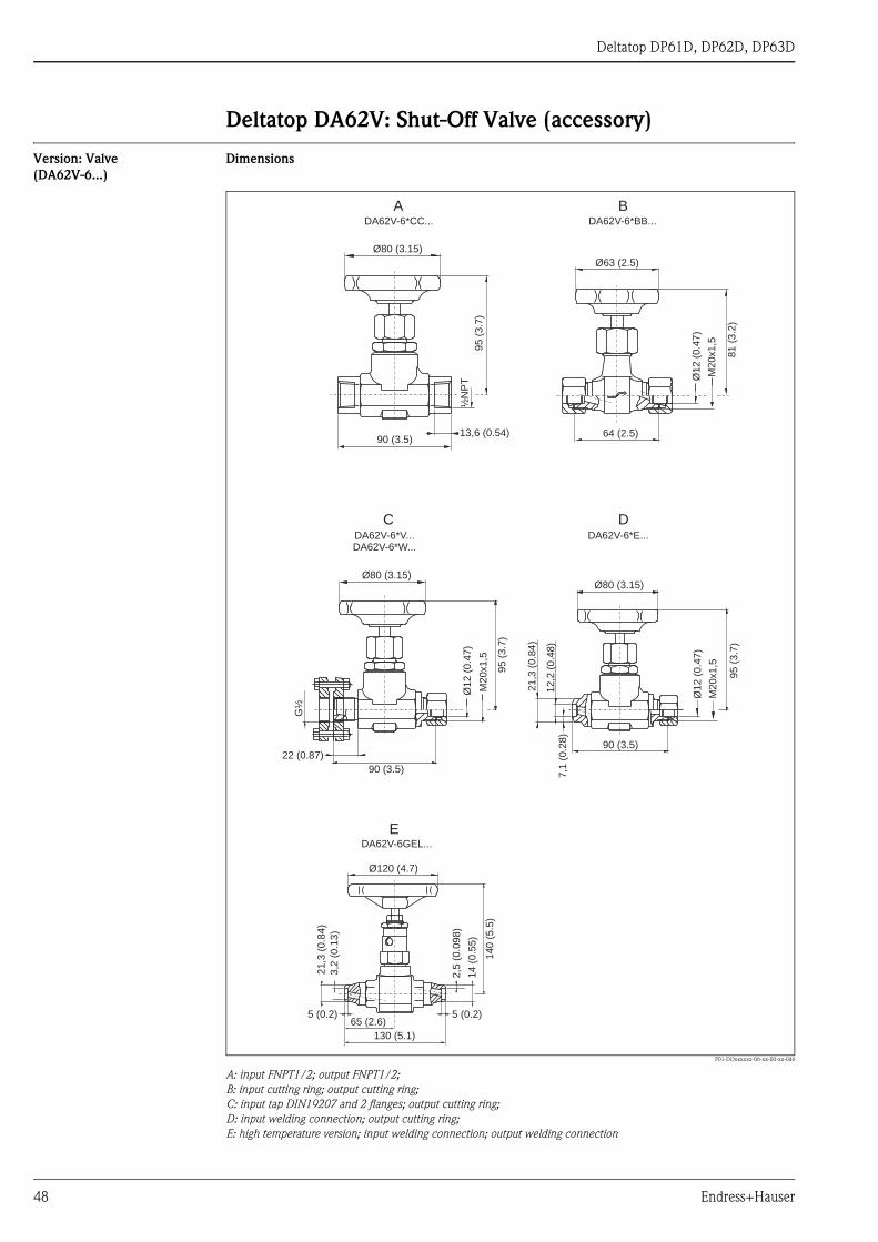
Deltatop DA62V: Shut-Off Valve (accessory)
Version: Valve
(DA62V-6...)
Dimensions
P01-DOxxxxxx-06-xx-00-xx-046
A: input FNPT1/2; output FNPT1/2;
B: input cutting ring; output cutting ring;
C: input tap DIN19207 and 2 flanges; output cutting ring;
D: input welding connection; output cutting ring;
E: high temperature version; input welding connection; output welding connection
Ø80 (3.15)
95
(3.7
)
½N
PT
13,6 (0.54)90 (3.5)
Ø63 (2.5)
81
(3.2
)
64 (2.5)
Ø1
2(0
.47
)
M2
0x1
,5
Ø80 (3.15)
95
(3.7
)
M2
0x1
,5
Ø1
2(0
.47
)
90 (3.5)
G½
22 (0.87)
Ø80 (3.15)
95
(3.7
)
M2
0x1
,5
Ø1
2(0
.47
)
90 (3.5)
21
,3(0
.84
)
12
,2(0
.48
)7
,1(0
.28
)
Ø120 (4.7)
14
0(5
.5)
5 (0.2)
14
(0.5
5)
2,5
(0.0
98
)
21
,3(0
.84
)
3,2
(0.1
3)
5 (0.2)65 (2.6)
130 (5.1)
A B
C D
E
DA62V-6*CC... DA62V-6*BB...
DA62V-6*V...DA62V-6*W...
DA62V-6*E...
DA62V-6GEL...
48 Endress+Hauser
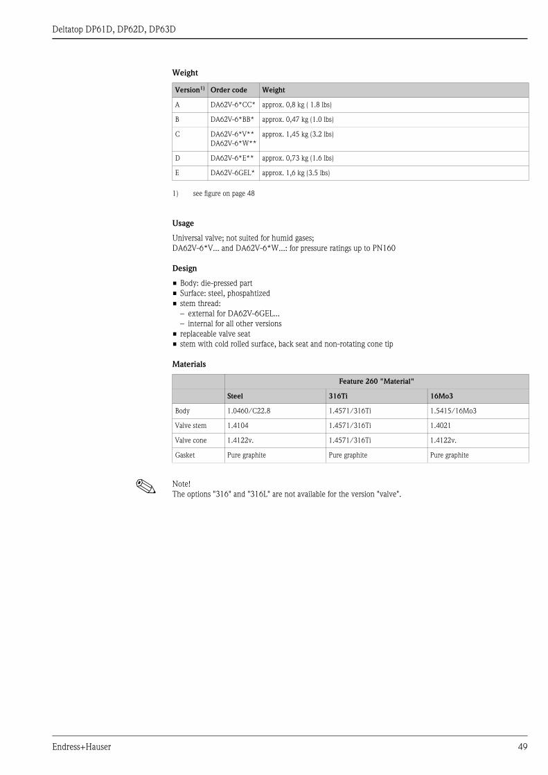
Deltatop DP61D, DP62D, DP63D
Weight
Usage
Universal valve; not suited for humid gases;
DA62V-6*V... and DA62V-6*W...: for pressure ratings up to PN160
Design
• Body: die-pressed part
• Surface: steel, phospahtized
• stem thread:
– external for DA62V-6GEL...
– internal for all other versions
• replaceable valve seat
• stem with cold rolled surface, back seat and non-rotating cone tip
Materials
! Note!
The options "316" and "316L" are not available for the version "valve".
Version1)
1) see figure on page 48
Order code Weight
A DA62V-6*CC* approx. 0,8 kg ( 1.8 lbs)
B DA62V-6*BB* approx. 0,47 kg (1.0 lbs)
C DA62V-6*V**
DA62V-6*W**
approx. 1,45 kg (3.2 lbs)
D DA62V-6*E** approx. 0,73 kg (1.6 lbs)
E DA62V-6GEL* approx. 1,6 kg (3.5 lbs)
Feature 260 "Material"
Steel 316Ti 16Mo3
Body 1.0460/C22.8 1.4571/316Ti 1.5415/16Mo3
Valve stem 1.4104 1.4571/316Ti 1.4021
Valve cone 1.4122v. 1.4571/316Ti 1.4122v.
Gasket Pure graphite Pure graphite Pure graphite
Endress+Hauser 49
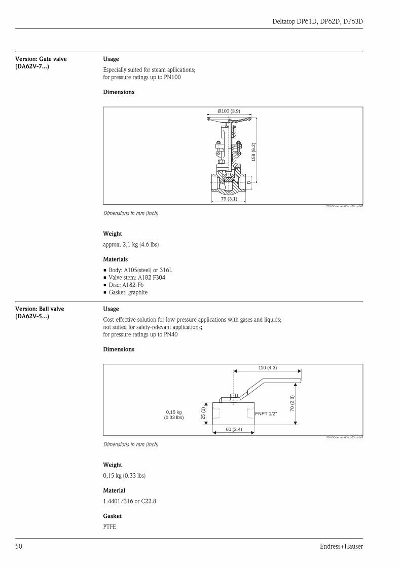
Deltatop DP61D, DP62D, DP63D
Version: Gate valve
(DA62V-7...)
Usage
Especially suited for steam apllications;
for pressure ratings up to PN100
Dimensions
P01-DOxxxxxx-06-xx-00-xx-042
Dimensions in mm (inch)
Weight
approx. 2,1 kg (4.6 lbs)
Materials
• Body: A105(steel) or 316L
• Valve stem: A182 F304
• Disc: A182-F6
• Gasket: graphite
Version: Ball valve
(DA62V-5...)
Usage
Cost-effective solution for low-pressure applications with gases and liquids;
not suited for safety-relevant applications;
for pressure ratings up to PN40
Dimensions
P01-DOxxxxxx-06-xx-00-xx-043
Dimensions in mm (inch)
Weight
0,15 kg (0.33 lbs)
Material
1.4401/316 or C22.8
Gasket
PTFE
79 (3.1)
D1
58
(6.2
)
Ø100 (3.9)
FNPT 1/2”
60 (2.4)
25
(1)
110 (4.3)
70
(2.8
)
0,15 kg(0.33 lbs)
50 Endress+Hauser
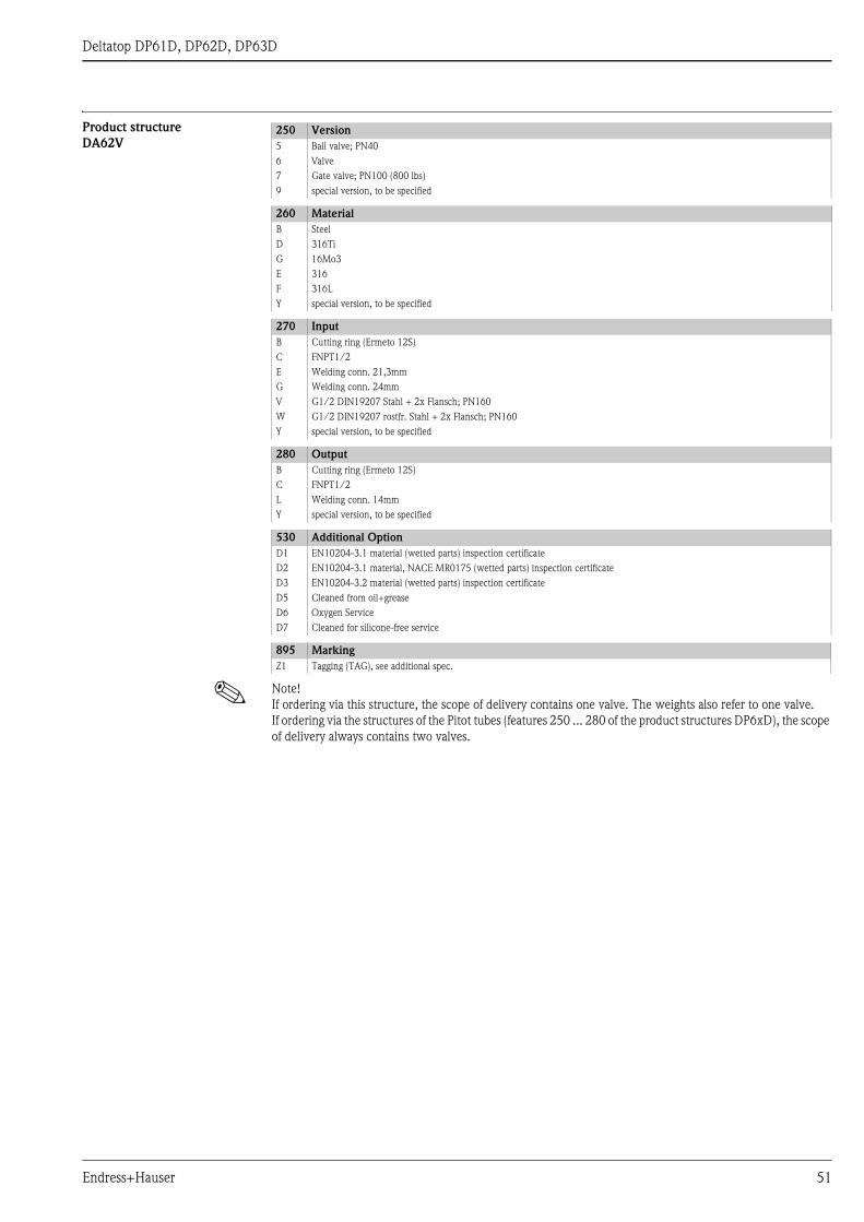
Deltatop DP61D, DP62D, DP63D
Product structure
DA62V
! Note!
If ordering via this structure, the scope of delivery contains one valve. The weights also refer to one valve.
If ordering via the structures of the Pitot tubes (features 250 ... 280 of the product structures DP6xD), the scope
of delivery always contains two valves.
250 Version
5 Ball valve; PN40
6 Valve
7 Gate valve; PN100 (800 lbs)
9 special version, to be specified
260 Material
B Steel
D 316Ti
G 16Mo3
E 316
F 316L
Y special version, to be specified
270 Input
B Cutting ring (Ermeto 12S)
C FNPT1/2
E Welding conn. 21,3mm
G Welding conn. 24mm
V G1/2 DIN19207 Stahl + 2x Flansch; PN160
W G1/2 DIN19207 rostfr. Stahl + 2x Flansch; PN160
Y special version, to be specified
280 Output
B Cutting ring (Ermeto 12S)
C FNPT1/2
L Welding conn. 14mm
Y special version, to be specified
530 Additional Option
D1 EN10204-3.1 material (wetted parts) inspection certificate
D2 EN10204-3.1 material, NACE MR0175 (wetted parts) inspection certificate
D3 EN10204-3.2 material (wetted parts) inspection certificate
D5 Cleaned from oil+grease
D6 Oxygen Service
D7 Cleaned for silicone-free service
895 Marking
Z1 Tagging (TAG), see additional spec.
Endress+Hauser 51

Deltatop DP61D, DP62D, DP63D
Deltatop DA62C: Condensate Pot (accessory)
Dimensions Volume: 300 cm3
P01-DOxxxxxx-06-xx-00-xx-044
Dimensions in mm (inch)
Volume: 20 cm3
P01-DOxxxxxx-06-xx-00-xx-045
Dimensions in mm (inch)
Weight
13
5(3
5.4
)
40
(1.6
)
21
,3(0
.84
)3
,6(0
.14
)
65 (2.6)
110 (4.3)
35
(1.4
)
21,3(0.84)
3,6 (0.14)
45 (1.8)
23
(0.9
)
42
(1.7
)
Volume Weight
300 cm3 approx. 1,4 kg (3.1 lbs)
20 cm3 approx. 1,4 kg (3.1 lbs)
52 Endress+Hauser
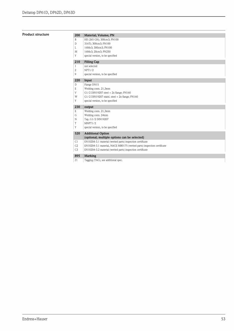
Deltatop DP61D, DP62D, DP63D
Product structure 200 Material; Volume; PN
B HII (265 GH); 300cm3; PN100
D 316Ti; 300cm3; PN100
L 16Mo3; 300cm3; PN100
M 16Mo3; 20cm3; PN250
Y special version, to be specified
210 Filling Cap
1 not selected
2 NPT1/2
9 special version, to be specified
220 Input
D Flange DN15
E Welding conn. 21,3mm
V G1/2 DIN19207 steel + 2x flange; PN160
W G1/2 DIN19207 stainl. steel + 2x flange; PN160
Y special version, to be specified
230 output
E Welding conn. 21,3mm
G Welding conn. 24mm
N Tap, G1/2 DIN19207
T MNPT1/2
Y special version, to be specified
520 Additional Option
(optional; multiple options can be selected)
C1 EN10204-3.1 material (wetted parts) inspection certificate
C2 EN10204-3.1 material, NACE MR0175 (wetted parts) inspection certificate
C3 EN10204-3.2 material (wetted parts) inspection certificate
895 Marking
Z1 Tagging (TAG), see additional spec.
Endress+Hauser 53
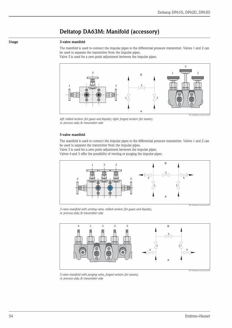
Deltatop DP61D, DP62D, DP63D
Deltatop DA63M: Manifold (accessory)
Usage 3-valve manifold
The manifold is used to connect the impulse pipes to the differential pressure transmitter. Valves 1 and 2 can
be used to separate the transmitter from the impulse pipes.
Valve 3 is used for a zero point adjustment between the impulse pipes.
P01-DOxxxxxx-14-xx-xx-xx-014
left: milled version (for gases and liquids); right: forged version (for steam);
A: process side; B: transmitter side
5-valve manifold
The manifold is used to connect the impulse pipes to the differential pressure transmitter. Valves 1 and 2 can
be used to separate the transmitter from the impulse pipes.
Valve 3 is used for a zero point adjustment between the impulse pipes.
Valves 4 and 5 offer the possibility of venting or purging the impulse pipes.
P01-DOxxxxxx-14-xx-xx-xx-015
5-valve manifold with venting valve, milled version (for gases and liquids);
A: process side; B: transmitter side
P01-DOxxxxxx-14-xx-xx-xx-016
5-valve manifold with purging valve, furged version (for steam);
A: process side; B: transmitter side
B
A
1 2
31
1
2
23
3
B
A
1 2
3
4 5
1 3 2
4 5
B
A
1 2
3
14 3 2 5
4 5
54 Endress+Hauser
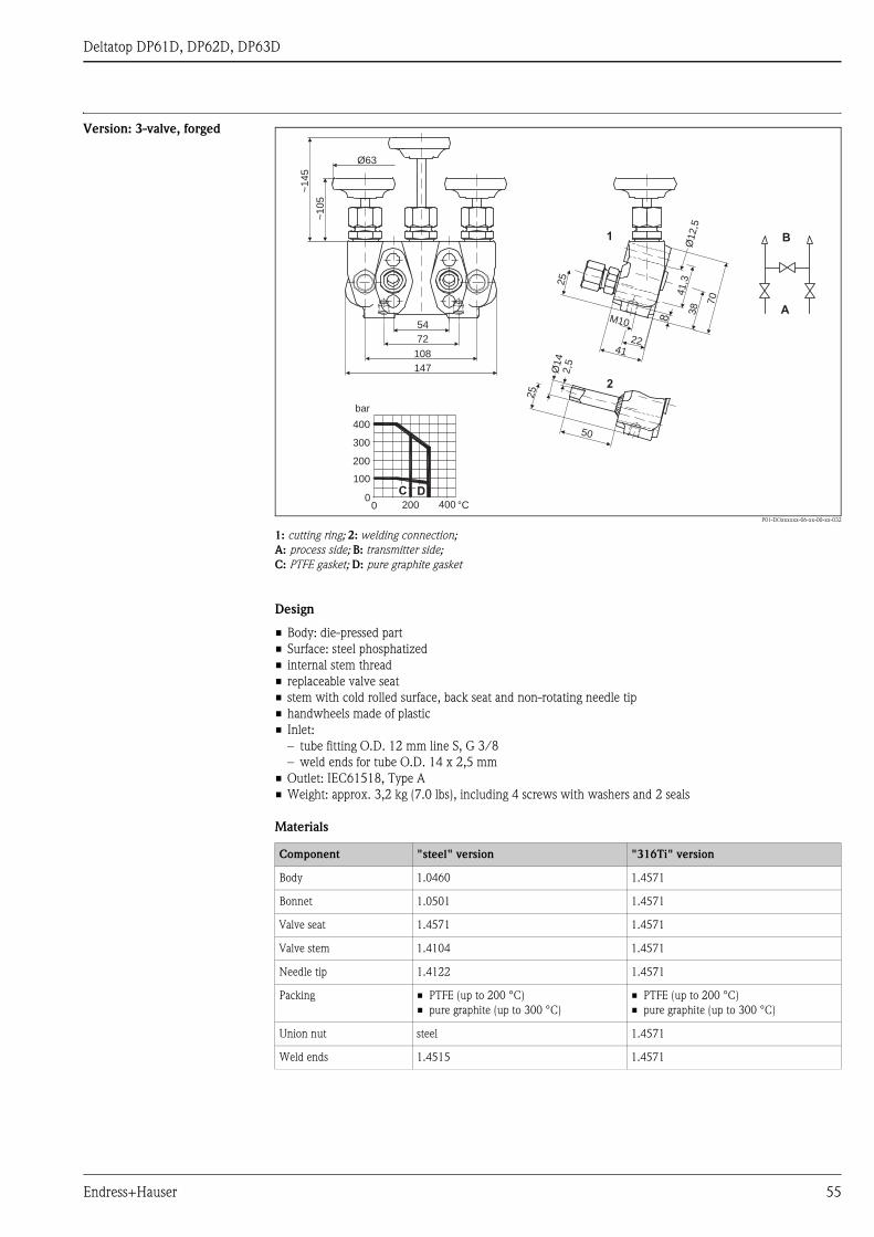
Deltatop DP61D, DP62D, DP63D
Version: 3-valve, forged
P01-DOxxxxxx-06-xx-00-xx-032
1: cutting ring; 2: welding connection;
A: process side; B: transmitter side;
C: PTFE gasket; D: pure graphite gasket
Design
• Body: die-pressed part
• Surface: steel phosphatized
• internal stem thread
• replaceable valve seat
• stem with cold rolled surface, back seat and non-rotating needle tip
• handwheels made of plastic
• Inlet:
– tube fitting O.D. 12 mm line S, G 3/8
– weld ends for tube O.D. 14 x 2,5 mm
• Outlet: IEC61518, Type A
• Weight: approx. 3,2 kg (7.0 lbs), including 4 screws with washers and 2 seals
Materials
54
72
108
147
~14
5
~1
05
Ø63
25
4122
M10 8
38
704
1,3
Ø12,5
2,5
Ø14
25
50
1
2
A
B
0 200 400 °C0
100
200
300
400
bar
C D
Component "steel" version "316Ti" version
Body 1.0460 1.4571
Bonnet 1.0501 1.4571
Valve seat 1.4571 1.4571
Valve stem 1.4104 1.4571
Needle tip 1.4122 1.4571
Packing • PTFE (up to 200 °C)
• pure graphite (up to 300 °C)
• PTFE (up to 200 °C)
• pure graphite (up to 300 °C)
Union nut steel 1.4571
Weld ends 1.4515 1.4571
Endress+Hauser 55
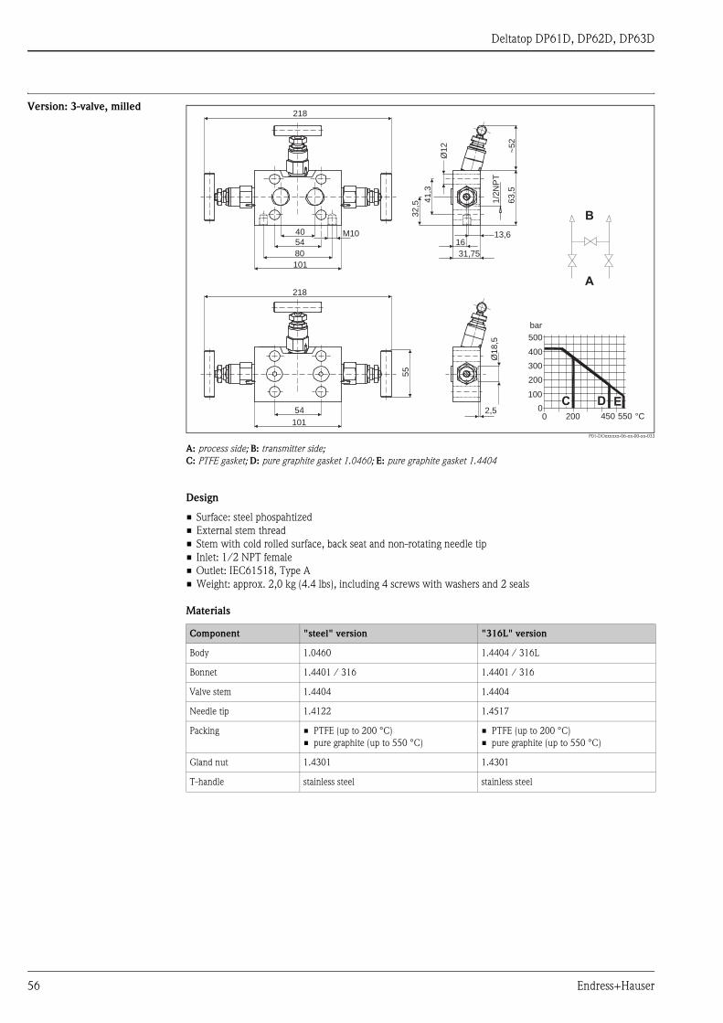
Deltatop DP61D, DP62D, DP63D
Version: 3-valve, milled
P01-DOxxxxxx-06-xx-00-xx-033
A: process side; B: transmitter side;
C: PTFE gasket; D: pure graphite gasket 1.0460; E: pure graphite gasket 1.4404
Design
• Surface: steel phospahtized
• External stem thread
• Stem with cold rolled surface, back seat and non-rotating needle tip
• Inlet: 1/2 NPT female
• Outlet: IEC61518, Type A
• Weight: approx. 2,0 kg (4.4 lbs), including 4 screws with washers and 2 seals
Materials
218
40
54
80
101
M10
55
218
54
101
13,616
31,75
32
,5
41
,3
Ø1
2
~5
26
3,5
1/2
NP
TØ
18
,5
2,5
A
B
0 200 450 550 °C0
100
200
300
400
500
bar
DC E
Component "steel" version "316L" version
Body 1.0460 1.4404 / 316L
Bonnet 1.4401 / 316 1.4401 / 316
Valve stem 1.4404 1.4404
Needle tip 1.4122 1.4517
Packing • PTFE (up to 200 °C)
• pure graphite (up to 550 °C)
• PTFE (up to 200 °C)
• pure graphite (up to 550 °C)
Gland nut 1.4301 1.4301
T-handle stainless steel stainless steel
56 Endress+Hauser

Deltatop DP61D, DP62D, DP63D
Version: 5-valve, milled, vent
P01-DOxxxxxx-06-xx-00-xx-034
A: process side; B: transmitter side; C: vent
D: PTFE gasket; E: pure graphite gasket 1.0460; F: pure graphite gasket 1.4404
Usage
Gas and liquid applications
Design
• Surface: steel phosphatized
• external stem thread
• stem with cold rolled surface, back seat and non-rotating needle tip
• Inlet: 1/2 NPT female
• Outlet: IEC61518, Type A
• Weight: approx. 3,3 kg (7.3 lbs), including 4 screws with washers and 2 seals
Materials
115
55
5480
105149
173~289
M10 16
13,6
31,75
1/2
NP
T
24
37
,5
1/4NPT
63
,5
41
,3
32
,5
Ø1
2
~5
2
A
B
C C
D E F
0 200 450 550 °C0
100
200
300
400
500
bar
Component "steel" version "316L" version
Body 1.0460 1.4404 / 316L
Bonnet 1.4401 / 316 1.4401 / 316
Valve stem 1.4404 1.4404
Needle tip 1.4122 1.4571
Packing • PTFE (up to 200 °C)
• pure graphite (up to 550 °C)
• PTFE (up to 200 °C)
• pure graphite (up to 550 °C)
Gland nut 1.4301 1.4301
T-handle stainless steel stainless steel
Screw plug 1.0501 1.4404
Endress+Hauser 57
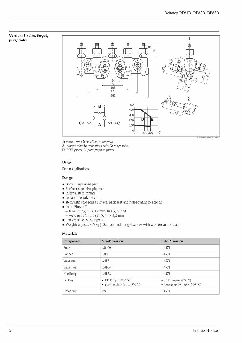
Deltatop DP61D, DP62D, DP63D
Version: 5-valve, forged,
purge valve
P01-DOxxxxxx-06-xx-00-xx-035
1: cutting ring; 2: welding connection;
A: process side; B: transmitter side; C: purge valve;
D: PTFE gasket; E: pure graphite gasket
Usage
Steam applications
Design
• Body: die-pressed part
• Surface: steel phosphatized
• internal stem thread
• replaceable valve seat
• stem with cold rolled surface, back seat and non-rotating needle tip
• Inlet/Blow-off:
– tube fitting, O.D. 12 mm, line S, G 3/8
– weld ends for tube O.D. 14 x 2,5 mm
• Outlet: IEC61518, Type A
• Weight: approx. 4,6 kg (10.2 lbs), including 4 screws with washers and 2 seals
Materials
54
72
108
175
252
51
7
8
38 50
25
41,3
Ø12,5
M10
2241
2,5
Ø14
25
50
2
1
A
B
C C
0
100
200
300
400
0 200 300 °C
bar
D E
Component "steel" version "316L" version
Body 1.0460 1.4571
Bonnet 1.0501 1.4571
Valve seat 1.4571 1.4571
Valve stem 1.4104 1.4571
Needle tip 1.4122 1.4571
Packing • PTFE (up to 200 °C)
• pure graphite (up to 300 °C)
• PTFE (up to 200 °C)
• pure graphite (up to 300 °C)
Union nut steel 1.4571
58 Endress+Hauser

Deltatop DP61D, DP62D, DP63D
Version: 5-valve HT, forged,
purge valve
P01-DOxxxxxx-06-xx-00-xx-036
A: process side; B: transmitter side; C: purge valve; D: PTFE gasket; E: pure graphite gasket
Usage
High temperature steam applications
Design
• Body: die-pressed part
• Surface: steel phosphatized
• Manifold: internal stem thread
• Purge valves: external stem thread
• replaceable valve seat
• Stem with cold rolled surface, back seat and non-rotating needle tip
• Inlet: butt weld end for tube O.D. 14 x 2,5 mm
• Outlet manifold: IEC61518, Type A
• Outlet purge valve: tube fitting O.D. 12 mm
• Weight: approx. 5,6 kg (12.4 lbs), including 4 screws with washers and 2 seals
Materials
d
170
230
11
30
22
41
50
L
5
21
,5
43
14
2
77
12,5
M1054
72
8
41
,3
A
B
C C
0
100
200
300
400
bar
0 200 550 °C
D E
Component "steel" version "316Ti" version
manifold purge valve manifold purge valve
Body 1.0460 1.5415 1.4571 1.4571
Bonnet 1.0501 1.7709 1.4571 1.4571
Valve seat 1.4571 1.4021 1.4571 1.4571
Valve stem 1.4104 1.4021 1.4571 1.4571
Needle tip 1.4122 1.4122 1.4571 1.4571
Packing PTFE pure graphite PTFE pure graphite
Union nut steel - 1.4571 -
Gland nut - 2.0550 - 1.4301
Endress+Hauser 59

Deltatop DP61D, DP62D, DP63D
Version: 3-valve, forged,
IEC61518, both side
P01-DOxxxxxx-06-xx-00-xx-037
A: process side; B: transmitter side; C: purge valve;
D: PTFE gasket; E: pure graphite gasket 1.0450; F: pure graphite gasket 1.4404
Usage
for the compact version of Deltatop
Design:
• Body: die-pressed part
• Surface: steel phosphatized
• External stem thread
• Stem with cold rolled surface, back seat and non-rotating needle tip
• Inlet: turned groove ∅18,5 acc. to IEC61518
• IEC61518, Type A
• Weight: approx. 2,2 kg (4.9 lbs), including 4 screws with washers and 2 seals
Materials
54
~201
12
1421325180
13,6
41
,3
61
~8
2
55
M8
Ø18
,5
A
B
C C
0
100
200
300
400
500
bar
0 200 450 550 °C
D E F
Component "steel" version "316Ti" version
Body 1.0460 1.4404 /316L
Bonnet 1.4401 /316 1.4401 /316
Valve stem 1.4404 1.4404
Needle tip 1.4122 1.4571
Packing • PTFE (up to 200 °C)
• pure graphite (up to 550 °C)
• PTFE (up to 300 °C)
• pure graphite (up to 550 °C)
Gland nut 1.4301 1.4301
T-handle stainless steel stainless steel
60 Endress+Hauser

Deltatop DP61D, DP62D, DP63D
Version: 5-valve, forged,
IEC61518, both side, vent
P01-DOxxxxxx-06-xx-00-xx-038
A: process side; B: transmitter side; C: vent;
D: PTFE gasket; E: pure graphite gasket 1.0460; F: pure graphite gasket 1.4404
Usage
for the compact version of Deltatop
Design
• Body: die-pressed part
• External stem thread
• Stem with cold rolled surface, back seat and non-rotating needle tip
• Inlet: turned groove ∅18,5 acc. to IEC61518
• Outlet (to transmitter): IEC61518, Type A
• Outlet (test/vent): 1/4 NPT female with screw plug
• Weight: approx. 3,3kg (7.3 lbs), including 4 screws with washers and 2 seals
Materials
~1
32
54
~229
12
14
35
95
41
,3
60
30
13,6
Ø1
8,5
A
B
C C
0
100
200
300
400
500
bar
0 200 450 550 °C
D E F
Component Material
Body 1.4404 / 316L
Bonnet 1.4401 / 316
Valve stem 1.4404
Needle tip 1.4571
Packing • PTFE (up to 200 °C)
• pure graphite (up to 550 °C)
Gland nut 1.4301
T-handle stainless steel
Screw plug 1.4404
Endress+Hauser 61

Deltatop DP61D, DP62D, DP63D
Product structure DA63M 300 Version
AA1 3 valve, steel, forging
AA2 3 valve, 316Ti, forging
AB1 3 valve, steel, milled
AB2 3 valve, 316L, milled
BB1 5 valve, steel, milled, vent
BB2 5 valve, 316L, milled, vent
CA1 5 valve, steel, forging, purge valve
CA2 5 valve, 316Ti, forging, purge valve
DA1 5 valve HT, steel, 16Mo3, forging, purge valve
DA2 5 valve HT, 316Ti, forging, purge valve
KA1 3 valve, steel, forging, IEC61518, both side
KA2 3 valve, 316Ti, forging, IEC61518, both side
LA2 5 valve, 316Ti, forging, IEC61518 both side, vent
YY9 special version, to be specified
310 Gasket
B PTFE, 200°C/392°F
C PTFE/pure graphite, HT
Y special version, to be specified
320 Process Connection
B FNPT1/2
C Cutting ring (Ermeto 12S)
D Welding conn. 14mm
E IEC61518
Y special version, to be specified
330 Seals; Screws
B PTFE; UNF7/16, max PN420
C PTFE; M10, max PN160
D Viton; UNF7/16, max PN420
E Viton; M10, max PN160
F Viton; M12, max PN420
Y special version, to be specified
540 Additional Option
(optional, multiple options can be selected)
E1 EN10204-3.1 material (wetted parts) inspection certificate
E2 EN10204-3.1 material, NACE MR0175 (wetted parts) inspection certificate
E3 EN10204-3.2 material (wetted parts) inspection certificate
E5 Cleaned from oil+grease
E6 Oxygen service
E7 Cleaned for silicone-free service
895 Marking
Z1 Tagging (TAG), see additional spec.
62 Endress+Hauser
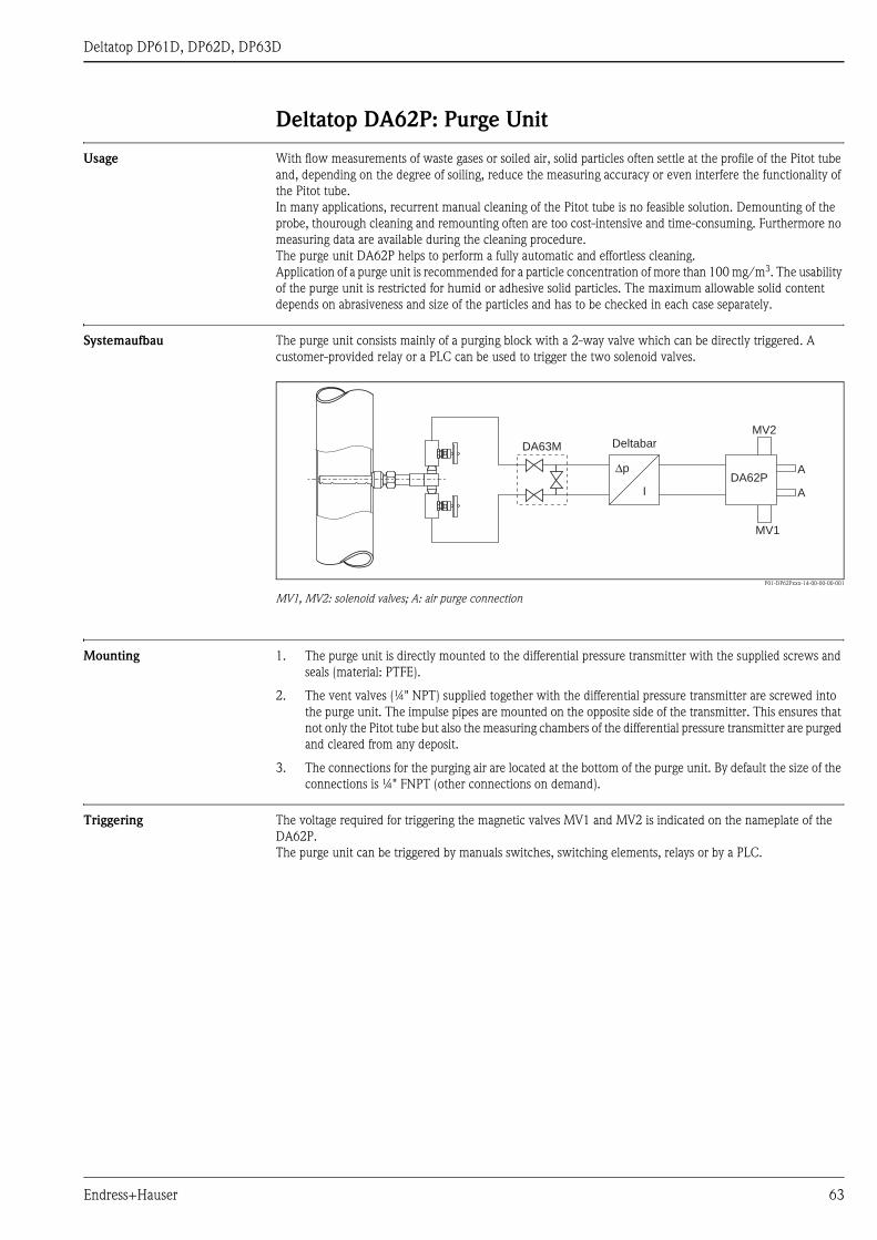
Deltatop DP61D, DP62D, DP63D
Deltatop DA62P: Purge Unit
Usage With flow measurements of waste gases or soiled air, solid particles often settle at the profile of the Pitot tube
and, depending on the degree of soiling, reduce the measuring accuracy or even interfere the functionality of
the Pitot tube.
In many applications, recurrent manual cleaning of the Pitot tube is no feasible solution. Demounting of the
probe, thourough cleaning and remounting often are too cost-intensive and time-consuming. Furthermore no
measuring data are available during the cleaning procedure.
The purge unit DA62P helps to perform a fully automatic and effortless cleaning.
Application of a purge unit is recommended for a particle concentration of more than 100 mg/m3. The usability
of the purge unit is restricted for humid or adhesive solid particles. The maximum allowable solid content
depends on abrasiveness and size of the particles and has to be checked in each case separately.
Systemaufbau The purge unit consists mainly of a purging block with a 2-way valve which can be directly triggered. A
customer-provided relay or a PLC can be used to trigger the two solenoid valves.
P01-DP62Pxxx-14-00-00-00-001
MV1, MV2: solenoid valves; A: air purge connection
Mounting 1. The purge unit is directly mounted to the differential pressure transmitter with the supplied screws and
seals (material: PTFE).
2. The vent valves (¼" NPT) supplied together with the differential pressure transmitter are screwed into
the purge unit. The impulse pipes are mounted on the opposite side of the transmitter. This ensures that
not only the Pitot tube but also the measuring chambers of the differential pressure transmitter are purged
and cleared from any deposit.
3. The connections for the purging air are located at the bottom of the purge unit. By default the size of the
connections is ¼" FNPT (other connections on demand).
Triggering The voltage required for triggering the magnetic valves MV1 and MV2 is indicated on the nameplate of the
DA62P.
The purge unit can be triggered by manuals switches, switching elements, relays or by a PLC.
Δp
I
Deltabar
DA62P
MV1
MV2
DA63M
A
A
Endress+Hauser 63

Deltatop DP61D, DP62D, DP63D
Technical data
Type of valve 2-way valve, directly triggered
Medium air
Operating mode normally closed
Pipe connection ¼" NPT
Mounting position arbitrary
Nominal diameter • Non-Ex area: 3 mm (0.12")
• ATEX: 2 mm (0.08 ")
flow coefficient Kv approx. 0,23 m3/h
Difference of operating
pressure
• Non-Ex area: max. 6 bar (87 psi)
• ATEX: max. 5 bar (72 psi)
Overall height of lift 1 mm (0.04")
Leak rate bubble tight
Temperature of medium • Non-Ex area: -10 ... +90 °C (14 ... +194 °F)
• ATEX: -10 ... +100 °C (14 ... 212 °F) for temperature class T6
Ambient temperature • Non-Ex area: max 55 °C (131 °F)
• ATEX: -30 ... +60 °C (-22 ... +140 °F) for single mounting
Material of valve chamber • anodically oxidized aluminium
• stainless steel
Material of inner parts stainless steel
Material of seals FPM
Nominal voltage • 230 VAC, 50 Hz
• 115 V AC, 50 Hz
• 24 VDC
Protection class for the ATEX version : EEx M II 2G/Dn T4; EEx EM II 2G/D T4
(PTB 00 ATEX 2129X)
On-time 100 %
Type of protection IP65
Electrical connection • Non-Ex area: according to DIN 43650
• ATEX: expansion-fit cable (3000 mm)
Power consumption • Non-Ex area: 21 VA AC (pick up); 12 VA / 8W (operation)
• ATEX: 7 W
Weight approx. 2,7 kg
64 Endress+Hauser

Deltatop DP61D, DP62D, DP63D
Dimensions
P01-DA62Pxxx-06-00-00-00-001
A: Vent valves ¼"NPT; B: Purge air connections ¼"FNPT (max. 3,5 bar [50 psi])
Product structure DA62P
228 (9.0)
114 (4.5)
58
(2.3
)4
0(1
.6)
70
(2.8
)
A A
B B
400 Approval
A non-hazardous area
B ATEX II 2G EEx m II T4
Y special version, to be specified
410 Power Supply
1 230V 50Hz
2 115V 50Hz
3 24VDC
9 special version, to be specified
420 Material Body Material
1 Aluminium
2 316Ti
9 special version, to be specified
430 Seals; Screws
B PTFE; UNF7/16
C PTFE; M10
D Viton; UNF7/16
E Viton; M10
F Viton; M12
Y special version, to be specified
550 Additional Option
(optional; several options can be selected)
FG Varistor, spark quenching
FH Varistor + LED, spark quenching
F1 EN10204-3.1 material (wetted parts) inspection certificate
F5 oil+grease free
F7 Cleaned for silicone-free service
F6 Oxygen service
F8 Pressure test + certificate
895 Marking
Z1 Tagging (TAG), see additional spec.
Endress+Hauser 65
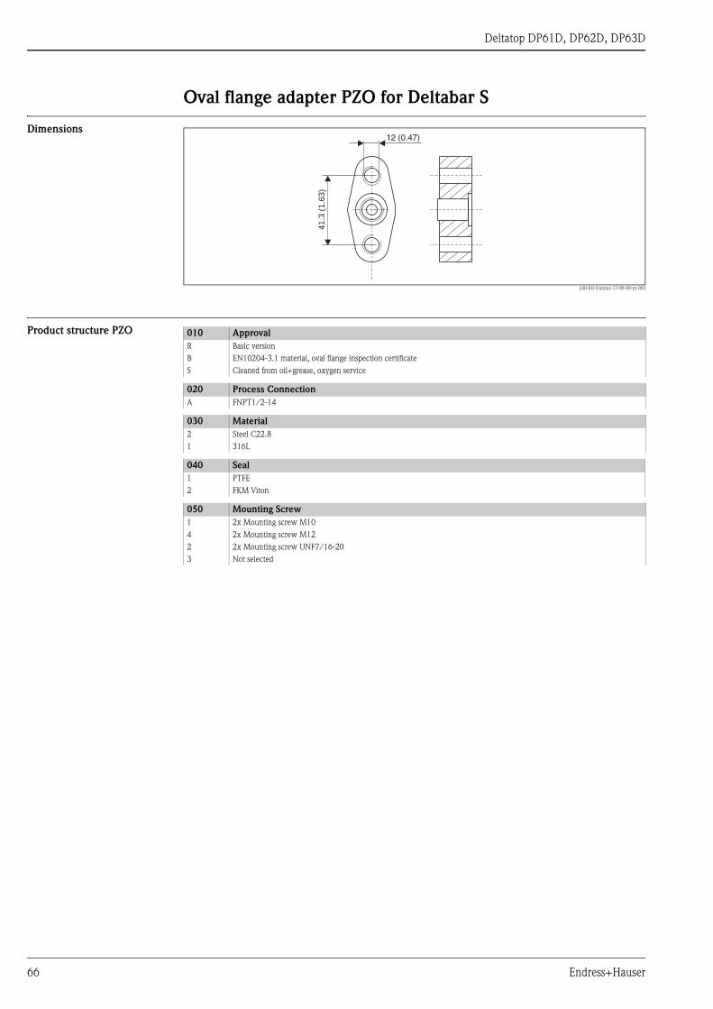
Deltatop DP61D, DP62D, DP63D
Oval flange adapter PZO for Deltabar S
Dimensions
L00-EH-Dummy-17-00-00-yy-003
Product structure PZO4
1.3
(1.6
3)
12 (0.47)
010 Approval
R Basic version
B EN10204-3.1 material, oval flange inspection certificate
S Cleaned from oil+grease, oxygen service
020 Process Connection
A FNPT1/2-14
030 Material
2 Steel C22.8
1 316L
040 Seal
1 PTFE
2 FKM Viton
050 Mounting Screw
1 2x Mounting screw M10
4 2x Mounting screw M12
2 2x Mounting screw UNF7/16-20
3 Not selected
66 Endress+Hauser

Deltatop DP61D, DP62D, DP63D
Sizing Sheet - Data Sheet
FLOWDATA3-EN
Sizing Sheet - data sheet / Pitot Tube Sheet 1/2Fields marked with * are mandatory to be filled-in
Project:
Customer: Project-No.: Contact partner:
Order code Order no.* Position(s) *
Primary element
Transmitter
Tag:
Medium: * Status * Gas Liquid Steam
Pressure * For gauge pressure the ambient pressure is additionally required if different from sea level.
absolute gauge ambient pressure:
Only for gases: The values for requested flow resp. density of the medium are based on the following conditions:
operating normal standard (acc. to reference conditions)
Flow rate * Reference temp.:
Density * Reference pressure:
*
Pressure: *
Temperature: *
The sizing will be based on the maximum requested flow and nominal pressure and temperature.
The maximum requested flow will be set as upper range value.
1) For clearly specified fluids (e.g. water or air) those entries are not mandatory.
2) For gases only. If there are no values available the sizing will be based on standard values or the ideal gas law.
Flowmeter
Nominal width: * Pressure rating:*
Pipe (round) * Rectangular duct
Inner diameter (DI): Duct height (H) :
Wall thickness (S): Duct width (W) :
Isolation thickness: Wall thickness (S):
Pipe material: Isolation thickness:
Pipe material:
The exact specification of the internal dimensions and wall thickness is absolutely necessary.
Nominal widths of DIN pipes DNxxx are not sufficient. Nominal widths of ANSI pipes including schedules according to ASME are sufficient.
Temperature transmitter not applicable for DP61D
without temperature sensor PT100 sensor with 4…20mA transmitter
PT100 sensor without transmitter Lower range value
Upper range value
Order Code
unit
Main Parameter
Operating Conditions
unit
Requested flow:
Mounting position s. sheet 2Pipe dimensions *
Additional Data
unitunit
unit
Isentropic index: 1,2)
unit *
Density: 1)
Viscosity: 1)
Z-factor: 1,2)
minimum nominal maximum
SDii SDii
Endress+Hauser 67

Deltatop DP61D, DP62D, DP63D
FLOWDATA4-EN
Sh
eet
2/
2
mou
nte
d lef
t
mou
nte
d r
igh
t
upw
ards
dow
nw
ards
mou
nte
d lef
t
mou
nte
d r
igh
t
upw
ards
dow
nw
ards
above
/ o
n t
op
bel
ow
/ a
t bott
om
upw
ards/
dow
nw
ards
upw
ards/
dow
nw
ards
mou
nte
d lef
t
mou
nte
d r
igh
t
mou
nte
d lef
t
mou
nte
d r
igh
t
upw
ards
dow
nw
ards
upw
ards
dow
nw
ards
Gas:
Ste
am
:
Siz
ing S
heet
- M
ou
nti
ng P
osi
tion
/ P
itot
Tu
be
rem
ote
, vert
ical
rem
ote
, h
ori
zon
tal
com
pact
, vert
ical
com
pact
, h
ori
zon
tal
com
pact
, vert
ical
com
pact
, vert
ical
Liq
uid
:
rem
ote
, vert
ical
com
pact
, h
ori
zon
tal
com
pact
, h
ori
zon
tal
rem
ote
, vert
ical
rem
ote
, h
ori
zon
tal
rem
ote
, h
ori
zon
tal
68 Endress+Hauser
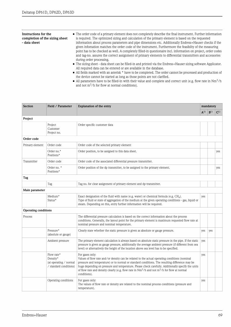
Deltatop DP61D, DP62D, DP63D
Instructions for the
completion of the sizing sheet
- data sheet
• The order code of a primary element does not completely describe the final instrument. Further information
is required. The optimized sizing and calculation of the primary element is based on the requested
information about process parameters and pipe dimensions etc. Additionally Endress+Hauser checks if the
given infomation matches the order code of the instrument. Furthermore the feasibilty of the measuring
point has to be checked as well. A completely filled-in questionaire incl. information on project, order codes
and tag-no. assures the correct assignment of primary elements to differential transmitters and accessories
during order processing.
• The sizing sheet - data sheet can be filled-in and printed via the Endress+Hauser sizing software Applicator.
All required data can be entered or are available in the database.
• All fields marked with an asterisk * have to be completed. The order cannot be processed and production of
the device cannot be started as long as those points are not clarified.
• All parameters have to be filled-in with their value and complete and correct unit (e.g. flow rate in Nm3/h
and not m3/h for flow at normal conditions).
Section Field / Parameter Explanation of the entry mandatory
A1) B1) C1)
Project
Project
Customer
Project no.
Order specific customer data
Order code
Primary element Order code Order code of the selected primary element
Order no.*
Positions*
Order position, to be assigned to this data sheet. yes
Transmitter Order code Order code of the associated differential pressure transmitter.
Order no. *
Positions*
Order position of the dp transmitter, to be assigned to the primary element. yes
Tag
Tag Tag no. for clear assignment of primary element and dp-transmitter.
Main parameter
Medium*
Status*
Exact designation of the fluid with name (e.g. water) or chemical formula (e.g. CH4).
Type of fluid or state of aggregation of the medium at the given operating conditions - gas, liquid or
steam. Depending on this, entry further information will be required.
yes
Operating conditions
Process The differential pressure calculation is based on the correct information about the process
conditions. Generally, the layout point for the primary element is maximum requested flow rate at
nominal pressure and nominal temperature.
Pressure*
(absolute or gauge)
Clearly state whether the static pressure is given as absolute or gauge pressure. yes yes
Ambient pressure The primary element calculation is always based on absolute static pressure in the pipe. If the static
pressure is given as gauge pressure, additionally the average ambient pressure (if different from sea
level) or alternatively the height of the location above sea level has to be specified.
yes
Flow rate*
Density*
(at operating / normal
/ standard conditions)
For gases only:
Values of flow rate and/or density can be related to the actual operating conditions (nominal
pressure and temperature) or to normal or standard conditions. The resulting difference may be
huge depending on pressure and temperature. Please check carefully. Additionally specify the units
of flow rate and density clearly (e.g. flow rate in Nm3/h and not m3/h for flow at normal
conditions).
yes
Operating conditions For gases only:
The values of flow rate or density are related to the nominal process conditions (pressure and
temperature).
yes
Endress+Hauser 69

Deltatop DP61D, DP62D, DP63D
Normal conditions For gases only:
The values of flow rate or density are related to normal conditions (pressure and temperature).:
Pressure: 101,325 kPa abs.
Temperature: 0°C (273,15 K)
yes
Standard conditions
(acc. to reference
conditions)
For gases only:
The values of flow rate or density are related to standard conditions (pressure and temperature):
Pressure: 101,325 kPa abs. (14,696psi abs.)
Temperature: 0°C (59 °F)
If there are other reference conditions to be considered, the values for those conditions have to be
clearly specified.
yes
Reference temp. Reference temperature at standard conditions yes
Reference pressure Reference pressure at at standard conditions yes
Req. flow Specification of the desired measuring range (minimum ... maximum) and of the operating point
(nominal). The measuring dynamics is typically between 1:3 and 1:6 (minimum : maximum). A
measuring dynamics of more than 1:10 usually requires cascading (split range) of several differential
pressure transmitters (see page 8). Too large measuring dynamics between the nominal and the
maximum flow can result in an increased measuring uncertainty at the operating point and should
be avoided.
yes yes
Pressure Static pressure in the pipe upstream (plus side) of the primary element. yes yes
Temperature Temperature of the fluid at the primary element. yes yes
Fluid properties Clearly defined liquids and gases like steam, oxygen, nitrogen, pure water or ethanol do not require
further entries of fluid properties. All necessary information about these data is easily accessible in
the relevant literature.Mixtures (e.g. natural gas) or brand names (e.g. Shell motor oil) do not
provide sufficient information for the calculation. More information is required. If the fluid
properties of a mixture are not clear, a list of ingredients and their composition can be attached to
this datasheet for clarification.The Endress+Hauser sizing tool Applicator provides a large medium
database with all necessary fluid properties for a big variety of fluids.
Density The density is an essential input value of the flow calculation. This field must be completed in case
of mixtures and brand names.
yes
Viscosity The influence of the viscosity value on the calculation is normally very small but the Reynolds No. is
a function of the viscosity. This may be a limiting factor fo the measurement expecially with highly
viscous liquids.
yes
Z-Factor For gases only:
The compressibility factor Z does have an influence on the density especially at higher pressure
and/or higher temperature. If the density is given at normal or standard conditions this may have a
quite big impact on the calculation result. If this value is not available, the calculation will be done
with the factor set to 1 or, in case of clear defined mixtures, with a factor calculated or estimated
from the ingredients.
yes
Isentropic index For gases only:
The isentropic index (or specific heat ratio) is required for the calculation of the expansion factor. If
the value is not available, the calculation will be done with standard values:
1,65 for monoatomic gases (e.g. Helium He)
1,4 for diatomic gases (e.g. nitrogen N2)
1,28 for triatomic gases (e.g. carbon dioxide CO2)
yes
Flowmeter
Nominal width* Nominal width of the pipe according to the relevant standards, e.g. DN200 (DIN) or 8" (ASME) yes
Pressure rating* Pressure rating of the selected connection (e.g. flange) according to the relevant standard, e.g.
PN40 (DIN) or Cl.600lbs (ASME).
yes
Pipe dimensions
Pipe (round) /
Rectangular duct
Selection fo the type of the duct. Only one option can be selected yes
Section Field / Parameter Explanation of the entry mandatory
A1) B1) C1)
70 Endress+Hauser

Deltatop DP61D, DP62D, DP63D
Inner diameter (DI) Mean inner diameter of the pipe. The precise inner diameter of the pipe is the basis of the
differential pressure calulation and determines the length of the probe in the pipe. Incorrect
specifications when ordering nresult in corresponding measuring errors or may cause that the probe
can not be mounted properly or can not be mounted at all. The inner diameter of the pipe is equal
to the length of the probe in the pipe. However, the inner diameter is NOT equal to the nominal
diameter. A pipe of the nominal diamter DN200 according to ISO may have inner diameters
between 194 mm and 215 mm depending on the pressure rating. For pipes according to ASME,
specification of the nominal diameter and the schedule No. is sufficient.
yes yes
Duct height (H) /
Duct width (W)
With rectangular ducts the inner pipe diameter is replaced by the inner dimensions of the duct
(height and width). From these dimensions the cross-sectional area is calulated, which is needed for
the differential pressure calculation. The Pitot tube is usually mounted parallel to the longer side of
the rectangular duct. Therefore, this dimension determines the length of the Pitot tube in the pipe.
Incorrect specifications in the order result in corresponding measuring errors or may cause that the
probe can not be mounted properly or can not be mounted at all.
Wall thickness (S) The wall thickness fo the duct is added to the total length of the Pitot tube. Precise specification is
essential.
yes
Isolation thickness Thickness of a possible thermal isolation of the pipe or of other covering shells. The isolation
thickness is added to the length of the neck of the probe. A missing specification may cause that the
Pitot tube can not be mounted properly (see page 28).
Pipe material Specification of the correct pipe material. The selected material of the mounting components should
match the pipe material in order to ensure weldability.
yes
Additional Data
Temperature
tranmsitter*
Temperature sensors can only be integrated into the device types DP62D and DP63D and for
pressure ratings up to PN40 (300lbs).
without temperature
sensor
An integrated temperature sensor is not required. yes
PT100 sensor without
transmitter
A PT100 temperature sensor is required, however without transmitter yes
PT100 sensor with
4...20mA transmitter
When selecting a PT100 sensor with 4...20mA transmitter, it is essential to specify the desired
measuring range.
yes
Mounting position
Mounting position A suitable mouting position in accordance with the situation on site can be chosen by marking the
check box below the pictogram. The chosen mouting position has to match the order code.
Endress+Hauser will check if there are any order code exclusions.
yes
1) A: mandatory for differential pressure calculation;
B: mandatory for instrument selection (material, pressure rating etc.);
C: mandatory for order processing (assignment of devices)
Section Field / Parameter Explanation of the entry mandatory
A1) B1) C1)
Endress+Hauser 71

Instruments International
Endress+HauserInstruments International AGKaegenstrasse 24153 ReinachSwitzerland
Tel. +41 61 715 81 00Fax +41 61 715 25 [email protected]
TI425P/00/en/10.07
FM+SGML 6.0 ProMoDo