technical information center u....
TRANSCRIPT

EVALUATION OF MECHANICAL EXCAVATION SYSTEMS FOR OIL SHALE MINING
Final Technical Report
By Levent Ozdemir Russell J. Miller William R. Sharp
July 1983
Work Performed Under Contract No. AC20-82LC10962
Colorado School of Mines Golden, Colorado
TECHNICAL INFORMATION CENTER U. S. DEPARTMENT OF ENERGY
DOEjLC/10962-1 (DE83016121 )

DISCLAIMER
This report was prepared as an account of work sponsored by an agency of the United States Government. Neither the United States. Government nor any agency thereof, nor any of their employees, makes any warranty, express or implied, or assumes any legal liability or responsibility for the accUracy, completeness"or usefulness of any information, apparatus, product, or process disclosed, or represents that its ulle would not infringe privately owned rights. Reference herein to any s~c commercial· product" process, or servIce by trade name, .. trademark, mal1ufacturer, orot~erwise does n<;rt,n~arily ~Stitute or imply its e~orsement, recommendation, or favoring by the UJI~ed States Government' or lI!Iy agency thereof. The views andopiriions of authors: expresseCIhCl"Cindonot'necessilrilys!ate or reflect those or the United States Govetnnlent or any !IgencYthereof~
This report has been reproduced directly from the best available copy.
Available from the National Technical Information Service, U. S. Department of Commerce, Springfield, Virginia 22161.
Price: Printed Copy A08 Microfiche AOI
Codes are used for pricing all publications. The code is determined by the number of pages in the publication. Information pertaining to. the pricing codes can be found in the current issues of the following publications, which are generally available in most libraries: Energy Research Abstracts (ERA); Government Reports Announcements and Index (GRA and I); Scientific and Technical Abstract Reports (STAR); .and publiCation NTIS-PR-360 available from NTIS at the above address. !'f.
,p/"- ~..t~" -.' r
to" I I I

EVALUATION OF MECHANICAL EXCAVATION SYSTEMS FOR OIL SHALE MINING
Final Technical Report
By
Levent Ozdemir Russell J. Miller William R. Sharp
July 1983
Contract No. DE-AS20-82LC-10962
Colorado School of Mines Excavation Engineering and Earth Mechanics Institute
Golden, Colorado 80401
DOE/Le/l0962-1 (DE83016121 )
Distribution Category UC-91

•

ABSTRACT
This report presents the result of an investigation into evaluating
the technical and economic feasibility of applying mechanical excavation
techniques to oil shale mining. The study was funded by the Department
of Energy, Laramie Technology Center. Based on the findings of this
investigation, it was concluded that mechanical excavation systems offer
a great potential for oil shale mining in term~ of high production and
reduced costs compared to conventional methods. While some of the systems
I
evaluated can be applied to oil shale economica,lly in their present stage
of development, others require additional impro!vements to ensure maximum
benefit and applicability for various aspects o:f oil shale mining operations.
It is also suggested that current mine design approaches may need to be I
modified to gain maximum advantage from potenti~l utilization of mechanical
excavation techniques.
i

I.
II.
III.
IV.
V.
VI.
VII.
TABLE OF CONTENTS
Page
INTRODUCTION. . . . . . . . . . . . . . . . 1
EVALUATION OF MECHANICAL EXCAVATION SYSTEMS FOR OIL SHALE MINING. 5
LABORATORY PHYSICAL PROPERTY AND CUTTING TESTS. .15
ECONOMIC EVALUATION .58
CONCLUSIONS • • 76 . RECOMMENDATIONS .79
REFERENCES. .80
APPENDICES. .81
Appendix A - Pictures of laboratory cutting tests in oil shale.
Appendix B - The theoretical relationship for calculating the penetration per revolution for a sharp disc cutter.
Appendix C - Penetration vs machine thrust for varied machine/ rock parameters.
Appendix D - Cost evaluation.
Appendix E - Minutes of conference on "Mechanical Excavation of Oil Shale" held at the Earth Mechanics, Institute, Colorado School of Mines on May 25, 1982.
ii
• . .,

LIST OF FIGURES
No.
1. Oil Shale - Density. . •. • .,
2. Oil Shale - Brazilian Tensile Strength
3. Oil Shale - Uniaxial Compressive Strength.
4. Oil Shale - Young's Modulus.
5. Oil Shale - Poisson's Ratio.
6. Oil Shale - Multifailure Triaxial Shear Strength
7. Linear Cutting Tests for Oil Shale
B. Linear Cutter Sieve Results.
9. Linear Cutter Sieve Results.
10. Linear Cutter Sieve Results.
11. Linear Cutter Sieve Results.
12. Linear Cutter Sieve Results.
13. Linear Cutter Sieve Results.
14. Real Time Machine 'J1hrust and Penetration
15. Real Time Machine RPM and Torque
16. Test 1 - Penetration
17. Test 1 - Thrust.
lB. Test 1 - Torque.
19. Test 1 - RPM ••
20. Test 2 - Penetration
21. Test 2 - Thrust.
22. Test 2 - Torque.
23. Test 2 - RPM •
24. Test 3 - Penetration
25. Test 3 - Thrust.
26. Test 3 - Torque.
iii
Page
16
17
IB
19
20
21
24
31
32
33
34
35
36
40
41
45
46
47
4B
49
50
51
52
53
54
55

LIST OF FIGURES (Cont.)
No. Page
27. Test 3 - RPM ••••••.••. .56
28. Thrust vs Torque for Oil Shale. .57
29. Penetration Rate vs Hachine Thrust. .64
30. H.P. vs Penetration Rate. .65
31. Comparison of Theoretical Penetration Rates vs Rock Strength. .69 t
32. Cost Comparison for Conventional Mining & Tunnel Boring Machine .71
33. Cost Sensitivity Comparison of Conventional vs Mechanical
Fragmentation • • • • • . . . . . . .72
34. Relative Sensitivity of Problem Parameters. .74
.-
iv

LIST OF TABLES
No. Page
l. Oil Shale Cutting - Test Results. .25
2. Oil Shale Cutting - Test Results. .26
3. Oil Shale Cutting - Test Results. .27
4. Oil Shale Cutting - Test Results. .28
~ 5. Oil Shale Cutting - Test Results. .29
6. Oil Shale Cutting - Test Results. .30 ~..;
7. Rotary Cutting Tests Performed. .39
8. Rotary Cutter Test Results. .42
9. Rotary Cutter Test Results. .43
10. Rotary Cutter Test Results. .44
11. Sample Problem. . . . . . . .67
v


..
I. INTRODUCTION
The needs for new energy sources and oil shale's potential role in
satisfying our nation's energy requirements are well documented. The
concern here is how to best facilitate the removal and processing of
the vast amounts of oil shale required for the envisioned industry.
The production rate often implied for a mature shale oil industry is
one million barrels of synthetic crude oil per day (BPD). This level of
productIon would require mining over one and a half million tons of oil
shale per day. To be able to take advantage of ,economies of scale, it is
estimated that individual projects will have to operate at a minimum
capacity of 50,000 BPD, with many having much higher levels of production. ,
It is evident that even the "small" oil shale op~rations will be faced
with the removal and handling of massive amounts of material, both before
and after processing. True in situ approaches wpuld mitigate this problem,
but that method has not been successffil to date .. The more feasible modified
in situ approach still requires the excavation a~d removal of very large ,
'. tonnages of material for development and the gen~ration of void volume.
For surface retorting operations, it is con$idered feasible to provide
the required retort feed from an underground roo$ and pillar mining operation,
although for a 50 , OOO-BPD· plant, the mine would ie larger than any current !
underground mine • Obviously, requirements for d~velopment, production !
headings, equipment, skilled labor, and material ,handling would be formidable.
Even open-pit mining faces requirements of simil4r magnitude, although more
experience exists in large-scale pit operations.
Under the constraints of current mining app~oaches and prejudices,
the costs of producing shale oil have kept ahead ,of world oil prices. It ,
would appear that it is time to consider new mining approaches or improvements '.
1

2
to existing methods that would better suit the scale of operations and the
particular characteristics of oil shale. With that in mind, the purpose
of this report is to evaluate the applicability of mechanical excavation
to oil shale; identify available machine types that are best suited to
various aspects of the mining operation; provide production and cost
estimates to allow a benefit analysis; present preliminary comments on the
configuration of an "ideal"dil shale mining machine; and establish the
background information necessary for conceptualizing and evaluating new
mining techniques using mechanical excavation equipment.
There are two separate aspects of a mining operation to which mechanical
excavation equipment would be applicable: development and production.
Since the needs of each can be quite different, it is important to consider
them separately in evaluating the suitability of mechanical excavation.
For underground mining, the evidence suggests that development headings
using full-face boring machines could actually progress fast·er than conventional
drill and blast, apparently at lower cost. This is not the only advantage;
factors such as a· more stable opening, uniform muck size, ease of muck
handling, better ventilation, less equipment, increased safety, and a reduced
manpower requirement would seem to make development by machine very attractive.
As full-face machines are not as flexible, it would be advantageous to use
development drives as long as possible in order to use the machines most
effectively. Partial~face machines can also be considered for development.
While their advance rate is considered to be less, the other advantages are
similar to the full-face machines,·and are definitely significant.
In a production mode, it is admittedly difficult to compete with
large-scale blasting in terms of costs for breaking rock. If, however,
the side benefits of mechanical excavation are taken into account, there is
an excellent chance that overall costs will be reduced. Considering, for
•
. .

3
example, an underground room and pillar mine, several advantages can be
identified: (1) reduced damage to roof and pillars, which will permit a
significantly higher extraction ratio, improved safety, and better ventilation;
(2) controlled, uniformly sized muck, minimizing or eliminating crushing,
improving material handling, and providing an optimum feedstock for certain
retorts; (3) ideally suited for integration with :a continuous material handling
system such as belts, a factor which has its own iadvantages in being continuous,
clean, and not requiring large numb.ers of trucks iand attendant maintenance,
safety, and ventilation considerations; (4) contfnuous in nature, not requiring
delays for blasting, mucking, sealing, and fumes iremoval; also eliminates the
variety of equipment associated with cyclic drill and blast, reduces or
eliminates the need for surge points in the systep1, and allows smoother
production planning; and (5) can be easily adapte'idto selective mining where
zones of desired grade can be mined sequentially br low-grade material can
be diverted for in-mine disposal.
Several of the advantages of mechanical excai'ration for an underground
mine should also be applicable to a surface opera~ion. Obviously, continuous
operation, uniform muck size, belt haulage, and tre ability to selectively
mine are attractive alternatives for potential su~face oil shale mines.
Currently, it is believed that there are no machi*,es capable of competing
with available large-scale pit mining concepts. ~owever, data concerning
rock-cutting tools and preliminary conceptualizat~ons strongly indicate that
machines could be designed and constructed to greatly increase the efficiency
of an open-pit operation. In particular, the abitity to improve average
grade through selective mining has been shown to dramatically improve
potential returns, even to the point where increa~ed mining costs could be ,
tolerated to effect such improved average grade. A similar conclusion seems
valid for underground mining as well.

4
This report presents the results of an investigation designed to evaluate
the technical and economic feasibility of applying mechanical excavation methods
to oil shale mining. The study was divided into three major phases: (1) a
detailed literature review of current mechanical excavation systems was under
taken to identify current equipment for potential application to mining of
oil shale, both for development and production work; (2) a series of labora
tory linear and rotary cutting tests were performed to provide a data base
for evaluation of the.cuttability of oil shale by various cutting tools and
techniques; and (3) an economic analysis was undertaken to determine the cost
savings that can be realized by utilizing mechanical excavation techniques in
preference of conventional drill and blast methods. The findings of all three
phases of investigation are presented and discussed in this report. Also
included in the Appendices are the minutes of a conference on "Mechanical
Excavation of Oil Shale" which was held at the Colorado School of Mines on
May 25, 1982.
!
:

5
II. EVALUATION OF MECHANICAL EXCAVATION SYSTEMS FOR OIL SHALE MINING
As part of this effort, both presently ava~lab1e and potential mechanical
excavation systems were evaluated for their potential for mining oil shale.
Capabilities, requirements, production rates, applications, and cost were
assessed for each machine type. Following is a discussion cf the various
,- mechanical excavation systems which were evalua~ed. . Continuous Miners
Both the ripper- and drum-type continuous miners utilize drag-type
cutter bits to break the rock. Depending on the rock type and particular
application, the cutter bits are either plow-type or conical (point-attack).
The conical bits are generally preferred for cutting harder materials and can
withstand larger shock loads. When used on continuous miners, the conical bits
rotate in their holder blocks and become self-sharpening. Both types of bits
are fitted with carbide tips brazed into the bit body.
Continuous miners are high-production machines with relatively low
capital costs. Because of the crawler mounting9' they are quite mobile and
can drive 90-degree crosscuts and negotiate shatp turns. There is easy access
to the cutting drum and to the face being cut. !Bits can be inspected and changed
with minimal effort. Roof supports, if needed, can be installed immediately
behind the machine.
The major disadvantage of the continuous miner is the limitation on
the amount of force that can be supplied to the cutting drum. The machines
are not braced against the roof or the side wa1]s and therefore the machine's
weight provides the sole reaction force for the :cutting operation. Because
of this, their application is limited to mining 're1ative1y soft rock. However,
heavier and more powerful machines have been bu~lt in recent years for cutting
harder material such as iron ore. Several manufiacturers have ongoing design
and development programs that will JilToduce contii,nuous miners for application

6
to harder rock.
Boring Type Continuous Miners
The boring-miners utilize twin rotors, each with three cutting arms,
a drum cutter, and a cutter trim chain for cutting an ovaloid opening. The
cutting action is similar to trepanning and produces larger cuttings than other
continuous miners. The cutting is accomplished with drag-bit cutter bits
mounted on the rotors, the drum, and the trim chain. The machine is crawler
mounted, providing the reaction force for the cutting action. The cuttings
are collected and transported behind the machine with a chain conveyor. The
largest machines built to date cut a face area 4 meters high and 6 meters wide
with an installed power of 15 HP. These machines, which are used in mining
potash, weigh as much as 205 tons.
Boom Type Continuous Miner
The steadily increasing application of roadheaders to the mining field
is due to the several advantages they offer over standard drum-type and boring
type continuous miner. The roadheaders can cut harder material than the
continuous miners because the machine power is concentrated over a smaller
number of bits. They produce less dust and can negotiate steep grades and
tight crosscuts. The machine operation is quite flexible and permits cutting
any size and shape cross-section (circular, horseshoe, arched, rectangular).
The cutter boom is easily accessible and therefore can be inspected and replaced
with minimal effort. Because of the smooth cutting action, the integrity of the
roof strata is not disturbed, resulting in savings in roof-support requirements.
Furthermore, if needed, roof supports can be installed at the face.
The major shortcoming of roadheaders relates to the production tate they
can achieve. These machines are part-face excavators; that is, only a portion
of the full-face can be cut at a given time. Therefore, they cannot match
the production capacities of full-face machines, such as TBMs or boring-type
continuous miners. In recent years, however, major improvements have been

..
7
made to increase the production capacity of roadheaders. High production rates
have been attained with new, heavier machines with large cutterheads or machines
with multiple cutting booms.
Undercutting Boring Hachine
Unlike TBHs, which attack the rock face frontally and cause rock
breakage through a combination of compressive-sh~ar-tensile failure, the Hini
and Hidi Fullfacers undercut the rock by creating a groove about 20 centimeters
behind the face and breaking the rock out to the face. The rotating cutterhead
is mounted on a horizontal axis at right angles to the tunnel axis. At
the start of a new cutting cycle, the cutterhead is in a downward tuck position.
As the cycle proceeds, the cutterhead is swung upward at an angle of 155 degrees
from its downward position. The cutterhead rotates at about two RPHs and
undercuts the rock using 8 to 14 peripherally fitted drag-bit cutter tools.
After it has moved to its maximum "up" position, the cutterhead starts to
return to initial downward position, still rotating and. directing muck into
the flight-chain conveyor at tunnel invert. The ,downward movement requires
about two minutes. No cutting occurs during dowqward movement. After the
cutterhead returns to its start position, the mashine is advanced forward and
the cutterhead resumes its upward swing action, ~aking another undercut approx
imately 20 centimeters behind the face. During the cut cycle, which usually
lasts about three to ten minutes depending on roqk hardness, the contractor
has time to haul muck and move back behind the machine .
Slot Hachine
Basically, the Slot Hachine works on the same principle as a tunnel-boring
machine (TBH) with the main difference being the ipositioning of the cutterhead.
Unlike a TBH, where the cutterhead rotates about la horizontal axis, the cutter
head of the Slot Hachine rO.tates on a vertical aXiis. This results in a
rectangular rather than a circular bo:r:e and is usi,ed in cutting a mine floor.
8
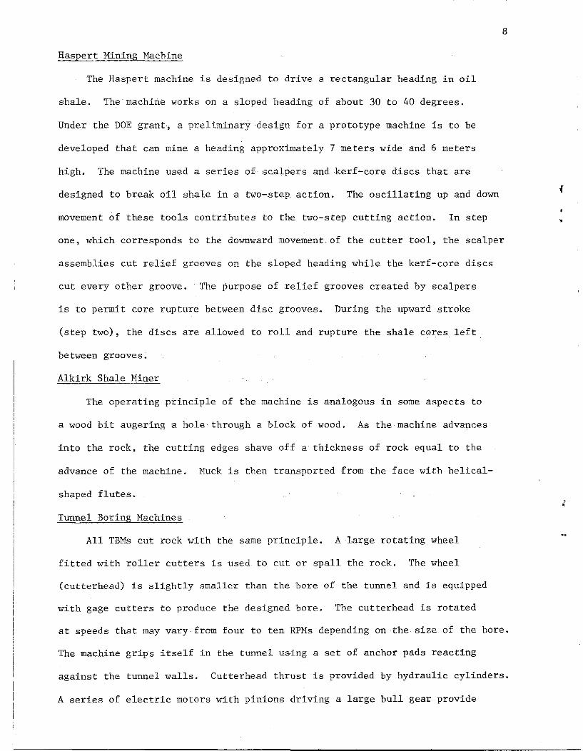
Haspert Mining Mac~ine
The Haspert machine is designed to drive a rectangular heading in oil
shale. The machine works on a sloped heading of about 30 to 40 degrees.
Under the DOE grant, a preliminary design for a prototype machine is to be
developed that can mine a heading approximately 7 meters wide and 6 meters
high. The machine used a series of scalpers and kerf-core discs that are
designed to break oil shale in a two-step_ action. The oscillating up and down
movement of these tools contributes to the two-step cutting action. In step
one, which corresponds to the downward movement of the cutter tool, the scalper
assemblies cut relief grooves on the sloped heading while the kerf-core discs
cut every other groove. The purpose of relief grooves created by scalpers
is to permit core rupture between disc grooves. During the upward stroke
(step two), the discs are allowed to roll and rupture the shale cores left
between grooves.
Alkirk Shale Miner
The operating principle of the machine is analogous in some aspects to
a wood bit augering a hole-through a block of wood. As the machine advances
into the rock, the cutting edges shave off a thickness of rock equal to the
advance of the machine. Muck is then transported from the face with helical-
shaped flutes.
Tunnel Boring Machines
All TBMs cut rock with the same principle. A large rotating wheel
fitted with roller cutters is used to cut or spall the rock. The wheel
(cutterhead) is slightly smaller than the bore of the tunnel and is equipped
with gage cutters to produce the designed bore. The cutterhead is rotated
at speeds that may vary from four to ten RPMs depending on the size of the bore.
The machine grips itself in the tunnel using a set of anchor pads reacting
against the tunnel walls. Cutterhead thrust is provided by hydraulic cylinders.
A series of electric motors with pinions driving a large bull gear provide
•
, ,

the required torque for rotating and cutting.
Mobile Miner
The mobile miner is a new machine concept that is currently under
development by the Robbins Company, the world's largest manufacturer of
tunnel-boring machines. Because of its propriet,ary nature, very little
information is available about the design and o~eration of this machine.
Through discussions with the Robbins Company, enough has been learned to
allow an analysis of its applicability to mining oil shale. The machine
uses disc cutters mounted on a rotating moveabl~ head. It can be considered
a partial-face machine,combiningthe mobility,flexibility, and light
weight of continuous miners and roadheaders, and providing the hard rock
capability and long cutter life of disc cutters.
Rectangular Boring Machine
A new concept in mine drifting machinery is presently in the research
and development (R&D) stage in Harrison-Western ',s engineering department.
The R&D group of Harrison-Western, under the direction of Larry Snyder, is
developing a machine to excavate rectangular mine entries and haulage ways
in hard rock. Combining existing technology with innovative machine design
has led to this new concept in mining machinery.
The concept is similar to the slot machine idiscussed earlier where a
typical TBM cutterhead has been turned on its s:Lde and rotates about a
9
nearly vertical axis. By using cutters on the t;op of the cutterhead a blind
entry can be excavated with a nearly rectangular: shape. This approach provides
the high productivity of a full-face machine wh:i!le creating a more desirable
rectangular entry for oil shale mining.
Based on the above presented literature re~iew of mechanical excavation
systems for oil shale mining application, the foil lowing conclusions were
drawn:

10
(1) The envisioned oil shale industry will require the removal and handling
of massive amounts of material, even for "small" mines.
(2) To make shale oil production competitive, it would appear that it is
time to consider new mining approaches or improvements to existing methods
that would better suit the scale of operation required for, and the particular
characteristics of, oil shale.
(3) Mechanical excavation techniques offer significant potential benefit
to the oil shale industry, and should be evaluated for optimal selection of
appropriate technologies.
(4) There are two separate aspects of a mining operation to which mechanical
excavation would be applicable: development and production. The two. appli-
cations need to be considered separately when evaluating the suitability of
mechanical excavation.
(5) For development headings, mechanical excavation offers the potential
for lower costs and higher advance rates. In addition, factors such as a
more stable opening, uniform· muck size, ease of muck handling, better venti-
lation, increased safety, and reduced manpower and equipment 'requirements
should make development by machine very attractive.
(6) Although admittedly it does not compete well with drill and blast,
mechanical excavation in production for an underground mine offers current,
and particularly future, significant benefits. Some of these advantages
include: (a) reduced damage to roof and pillars, which will permit a
significantly higher extraction ratio, improved safety, and better ventila-
tion; (b) uniform, controlled muck size, minimizing or elimination crushing,
improving material handling, and providing an optimum feedstock for certain
retorts; (c) ideally suited for integration with a continuous material hand-
. ling system such as belts, which has its own advantages in being continuous,
clean, and not requiring large numbers of trucks and attendant maintenance,
safety, and ventialtion requirements; (d) continuous in nature, and not
, ..

11
requiring delays for blasting, mucking ,scaling, and fumes removal; also
eliminates the variety of equipment associated with cyclic drill and blast,
reduces or eliminates the need for surge points in the system, and allows
smoother production planning; and (e) can be easily adapted to selective
mining, where zones of desired grade can be mined sequentially, or low-grade
material can be diverted for in-mine disposal.
(7) Many of the advantages of mechanical excavation for an underground mine
should also be applicable to a surface operation. Continuous operation,
uniform muck size, belt haulage, and the ability to selectively mine should
be attractive alternatives for surface oil shale mfnes. In particular, the
ability to improve average grade through selective mining has been shown to
dramatically improve potential returns, even to the point where increased
mining costs could be tolerated to effect such impr!oved average grade.
(8) Extensive theoretical and experimental investigations, both here and
abroad, provide an excellent base for evaluating the potential performance
of individual machines, and for determining actual capabilities rather than
relying on some times overly optimistic manufacturers' claims.
(9) Rock cutting tools corne in a wide variety of sizes, shapes, and styles.
These cutters, however, can be grouped into two major categories: Drag-'bit
cutters, using a milling or ripping action; and roller cutters, using a
crushing and chipping action. Drag-bit cutters are usually used in softer
.- formations, whereas roller cutters are best suited to harder, more brittle
rock types.
(10) Oil shale tends to span the range between properties best suited for
drag-bit cutting, up to strengths and hardnesses that generally dictate a
roller-cutter approach. With rock properties in this crossover range, it
becomes critical to evaluate the relative characteristics of the various
cutter types in making a decision as to the most appropriate mechanical /
excavation system for oil shale.

(ll) Drag-bit cutter forces increase ,nearly linearly with penetration.
Efficiency,or energy per unit volume of rock, improves with depth until
a critical depth is reached. For each pick type and rock there is an optimum
depth of cut per pass.
(12) Pick cutter spacings and lacing pattern dramatically affect machine
cutting efficiency,Knowing the pick type and rock properties, it 'is possible
to identify proper pick placement for optimum performance.
(13) Pick rake angles can be selected for use in oil shale so as to balance
pick loads, increase efficiency, alid minimize wear.
(14) Cutting speed seems to have only a limited effect on pick performance,
but can adversely affect pick life because of heat dissipation problems at
higher speeds.
(15) For 'planer:...type bits, in which ai~edge of a given width makes up the
cutting edge, the ~idth and shape of that edge control cutter forces and
efficiency;' Using this type of bit and its configuration depends on the type
of rock to be cut. Actual trials are about the onlY'wayto evaluate the
efficiency of these bits.
(16) For drag-bit cutting, cutter wear develops more rapidly ,and ,greatly
influences overall'efficiency. Even small amounts of wear can cause large
increases 'in pick forces required for a give'n penetration.
(17) Mhennew, the wedge bit is more ef1ficie,nt than a point-attack bit,
but as wear progresses, point-attact bits quickly become more efficient, and
may actually experience a reduction in required pick force's.
(18)'The use of water jets in conjunction with drag-bit cutters looks,
promising for'extending the range of rock types suitable for drag-bit cutting,
increasing ef:ficiency, and reducing wear.
(19) The most efficient type of roller cutter, and' the only one recommended"
is the single disc cutter with a continuous edge.
12
:

.'
13
(20) ~ile roller-cutter forces do increase with increasing penetration,
efficiency of cutting also improves. No limit to this effect has been found,
indicating depths of cut should be the maximum allowed by cutter-bearing
capacity.
(21) As for drag-bit cutters, spacing was found to have a dramatic effect
on cutting efficiency of roller cutters. There is,an optimum range of
cutter spacing related to the achievable penetrati~n.
(22) Roller-cutter edge angle affects penetrationf and therefore, efficiency.
Strength and wear considerations will, however, pr9bably dictate the choice
of edge angle.
(23) Roller-cutter diameter has only a small effect on cutter forces required
for a given penetration. However, bearing capacit~ increases significantly
with increased cutter diameter, thus higher penetr1tiOns are attainable,
resulting in increased efficiency.
(24) Cutting velocity was seen to have little or *0 effect on roller-cutter
performance, and need only be limited to prevent oYerheating.
(25) For roller cutters operating at efficient sp~cings, edge wear, unlike
for drag-bit cutters, did not significantly affecticutter performance.
(26) The presence of foliation or other planes of:weakness can greatly
affect the cutting efficiency of both roller- and 4rag-bit cutting. The
most efficient direction to cut is perpendicular t~ the planes of weakness,
with up to a threefold reduction in forces observeq in some cases for this
direction of cut. Since oil shale is characterizeq by significant planes of
weakness along its varve structure, a machine design that would take advantage ,
of this preferential direction of cutting would be highly advantageous.
(27) Cutterhead shape has an effect on cutting efficiency and stability,
with an optimum possible for each machine and cutt~r type. !
(28) Full-face machines, where the cutterhead is in contact with the entire ,
cross section to be cut, generally have a higher p~oduction rate. They
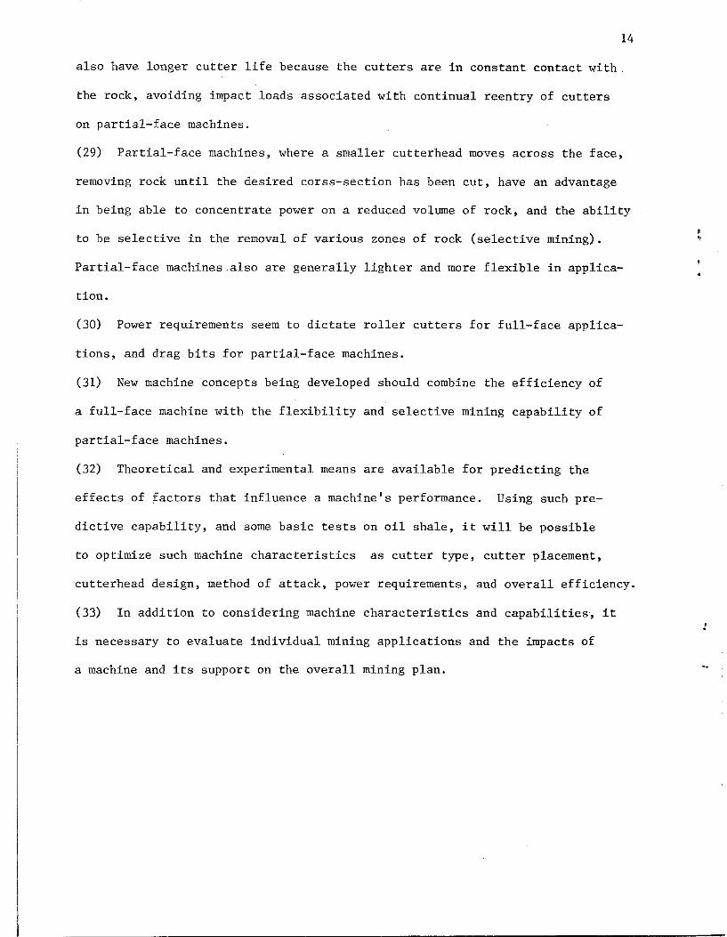
14
also have longer cutter life because the cutters are in constant contact with.
the rock, avoiding impact loads associated with continual reentry of cutters
on partial-face machines.
(29) Partial-face machines, where a smaller cutterhead moves across the face,
removing rock until the desired corss-section has been cut, have an advantage
in being able to concentrate power on a reduced volume of rock, and the ability
to be selective in the removal of various zones of rock (selective mining).
Partial-face machines also are generally lighter and more flexible in applica
tion.
(30) Power requirements seem to dictate roller cutters for full-face applica
tions, and drag bits for partial-face machines.
(31) New machine concepts being developed should combine the efficiency of
a full-face machine with the flexibility and selective mining capability of
partial-face machines.
(32) Theoretical and experimental means are available for predicting the
effects of factors that influence a machine's performance. Using such pre
dictive capability, and some basic tests on oil shale, it will be possible
to optimize such machine characteristics as cutter type, cutter placement,
cutterhead design, method of attack, power requirements, and overall efficiency.
(33) In addition to considering machine characteristics and capabilities, it
is necessary to evaluate individual mining applications and the impacts of
a machine and its support on the overall mining plan.
15
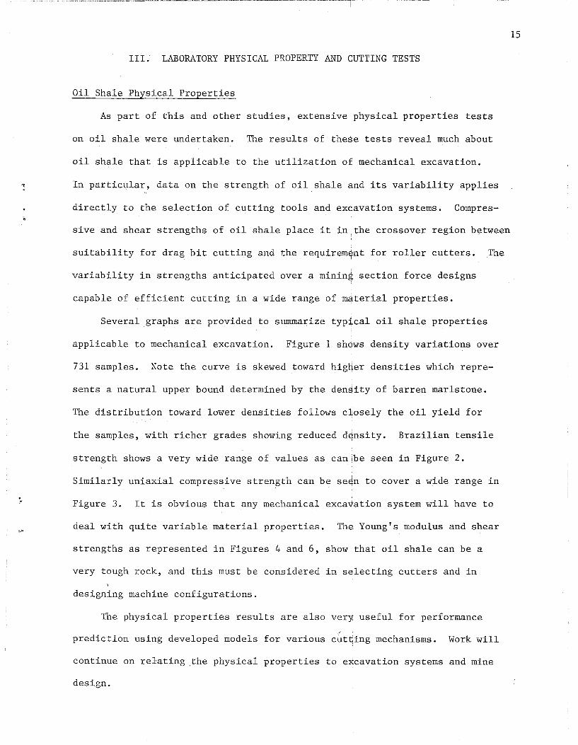
III. LABORATORY PHYSICAL PROPERTY AND CUTTING TESTS
Oil Shale Physical Properties
As part of this and other studies, extensive physical properties tests
on oil shale were undertaken. The results of these tests reveal much about
oil shale that is applicable to the utilization of mechanical excavation.
In particular, data on the strength of oil shale and its variability applies
directly to the selection of cutting tools and excavation systems. Compres-
sive and shear strengths of oil shale place it in the crossover region between
suitability for drag bit cutting and the requirem~nt for roller cutters. The
variability in strengths anticipated over a mining section force designs
capable of efficient cutting in a wide range of m4terial properties.
Several graphs are provided to summarize typ~cal oil shale properties
applicable to mechanical excavation. Figure 1 shows density variations over
731 samples. Note the curve is skewed toward higijer densities which repre-
sents a natural upper bound determined by the den~ity of barren marls tone.
The distribution toward lower densities follows c~osely the oil yield for
the samples, with richer grades showing reduced d~nsity. Brazilian tensile
strength shows a very wide range of values as canibe seen in Figure 2.
Similarly uniaxial compressive strength can be se~n to cover a wide range in
Figure 3. It is obvious that any mechanical exca~ation system will have to
deal with quite variable material properties. Th~ Young's modulus and shear
strengths as represented in Figures 4 and 6, show that oil shale can be a
very tough rock, and this must be considered in selecting cutters and in
designing machine configurations.
The physical properties results are also very useful for performance
/
prediction using developed models for various cut~ing mechanisms. Work will
continue on relating .the physical properties to excavation systems and mine
design.

16
o
,..,..,
L{)
I:D CD r--
.... ..... .... "J (V) ~
(\.1 0 t""- II II 11 II
I • <
::;6 0
W 1\ Lr>
Cl Z
I'J
a: Cl W l-:L (f) Z
l.{) , (\J
~ Ir~ H Ul Z
"" ...... >=l
"" p::
"" ::0 °c t:> ~
,0 I
H , . ( )
~ :0:: '(-"J .. -:-Ul ....
..:l ..L
~ (...!:) 0
tD r--

LJ.J C') 0::1: ~-
:~
(1)
U·.I
<:1"-
W('!-,-CJ u: LLJ CL
nJ
.-.
J L::.I_ ... _. __
I
(I. DO
~
r , 3i}.OO
'.11..-A', ~ " ....
FIGURE 2
OIL SHALE - BRAZILIAN TENSILE STRENGTH
MERN = 1031.97 ,
STO OEV = 473.17
N = 732
.- I GO.OG 90.00
p~; I f I I
120.00 150.00 180.00 ~lO
240.00 ,..... "
J

FIGURE 3
OIL SHALE - UNIAXIAL COMPRESSIVE STRENGTH
w
If:l
"7
llJ (,9 cr 1-----,. .. :.-llJ ,'., (-)
CC LLJ LL
0_1 r- 1
0.00 30.00 60.00
'[ ....
NERN = 10876.19
5TD DEV = 4798.79
N = 520
1 90.00 1._ 0-- 1 ill 1_ co. 00 I SO 0 _ 1 n P '::.; III 0 ~ . U 1 8 0 . (1 0 -~.,. -"---i . c.. I,.'JU )'1'~ iIl-L- .)"wJ I-' CD

r- C\J ....... .... C\J -
J II II
> w 0
Z c: 0 lJ.J I-L (f)
00 ::> ...:l ::> Cl
~ 00 -
"'" 0 z ~ ::> p:: 0
8 >< H r...
~ ...:l ;J 00
...:l H 0
"
..
01
en ....... II)
II
Z
8 8 1> 3~tJ1N3J!:Eld
o Co
0 Co
r-
0 Co
CD
0 Co
LJ)
19
oCD Co I
';'!J<! !J<!
0 .,.......
X 0 ...... Co tr:J ;'0...
0 Co
('\J
0 Co
~-~----Io o
00

0 (t",
Co
II
Z 0::1: UJ z:
0 1-1 H
~ til
~ U"I til
til ~. H
~ 0 p.,
c.!l 1-1 I ~
~
~ til
,..:l 1-1 0
I
Oi
(\1 ..... on ...... Co If)
II II
:> I..!..J Cl
Cl I-If) z
I
8 g \7 "J C) W I ~.J"] .-; U"] I ~ '_ .1_' .J... i \ ...J ._' t...,J ....J (::J
I
2
o r.o
0 If')
0
20
0° ~ ...... • J-
CC
'-

['--
.. £0 LtJ C~I
0:
z w C_) u=~·
-w--"CL
('<,
'"\1
-. I n
", ~A
FIGURE 6
OIL SHALE - MuLTIFAILURE TRIAXIAL SHEAR STRENGTH
J~
MEAN = 3464.29
STO DEV = 1526.04
N = 131
Co [_~ +- ----r---' I -,- I I' I I I
0.00 10.00 20.00 10.00 40.00 ~O.OO 60.0070.00 80.00 PSI :*:10 N .....

22
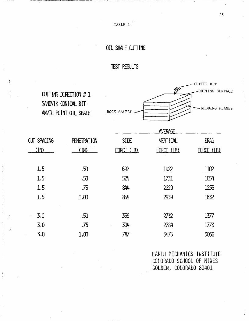
Linear Cutting Tests
To determine the effect of direction of cut, and to evaluate various
cutting tools" several tests were performed on oil shale of approximately
30 gpt using the full,-scale linear cutting machine available at the Earth
Mechanics Institute, colorado School of Mines. Cutters used included a
Sandvik long shank concial bit as used in trials at Colony oil shale mine,
t and a Robbins disc cutter with both a 75 degree cutting edge and a constant ,
cross section type cutting edg,e. Three directions of cut relative to the
bedding planes or varve structure were used for these tests. The main
objective was to determine the effect of bedding direction on the cuttability
of oil shale. A representation of the three directions is provided in
Figure 7.
For each bedding direction, an extensive series of tests was undertaken
both with conical bit and the disc cutter. Tests were carried out at various
cutter spacings and penetrations while the cutting speed was held constant
at 10 in/sec. Each test consisted of a series of four or five passes over
the rock surface ,with the tool, with each pass containing an average of ten
cuts. At the completion of each pass, the cuttings were collected for sieve
analysis. 'Visual observations were made of the chipping mechanism during
cutting.
The results of the linear cutting tests are presented in Tables 1
through 6. Several pictures of the cutting tests are given in Appendix A.
Although there is considerable scatter in the results due to the variability
of oil shale (grade varied from 10 to 35 gpt with an average of 30 gpt) ,
several trends are apparent. As expected, all three components of cutter
forces; side, vertical and drag increase with increased penetration and/or
spacing between cuts. A dramatic difference in cutting forces relative to
direction being cut is evident, with direction number 1 being by far the
easiest. This particular direction of cutting allows fracture propogation

along bedding planes, requiring minimal effort for the cutter to remove the
interlying material between adjacent cuts. It is obvious that any design
of mechanical equipment for mining oil shale should take advantage of this
directional cutting property which oil shale exhibits. It is also apparent
that pick cutters are more efficient for a given thrust, but require greater
drag forces, meaning higher torque requirements on a machine.
To determine chip size distribution, sieve arialyses were performed on
the cuttings generated from each test. The results confirmed the observations I
and the conclusions drawn from cutter force data. As can be seen in Figures 8
and 9 cutting in direction 1 resulted in larger chips and fewer fines for ,
both the Sandvik pick and the Robbins disc cutter.' It was also found that I
the pick cutters generated larger chips and less flines, with more airborne
dust, however. Figure 10 shows little effect of d!epth of cut on particle
size distribution, and only a slight effect of doU!bling the spacing can be
seen from Figure 11. The relative differences in !size distributions, and I
therefore, efficiency, between pick cutter and dislc cutter can be clearly
seen in Figures 12 and 13. Where fines may be a p~oblem, or if a specific
23
muck size is desired, the selection of cutters andl spacing may become critical.
An important factor which must be considered ~n the selection of an
I
appropriate cutting tool for oil shale mining is the bit wear. Due to the I
limited amount of cutting, no quantitative analysi~ of bit wear could be
accomplished from the tests conducted as part of this study. Although the
conical bit is found to be more efficient in terms! of cutting performance !
and chip size, it suffers a higher degree of wear ~han disc type cutters
I
and therefore, may not be applicable for mechanica~ excavation of lower
grade, harder oil shale formations. It is obviousi that the bit wear should
be included in any final analysis leading to the. selection of a particular
type of cutting bit to be utilized on a mechanical I excavation system for
oil shale mining.

FIGURE 7 24
LIffAR CUllING TESTS FOR OIL SHALE
CurrING DIRECTION # 1
ROCK SAMPLE""""""'" -----
CUTTING DIRECTION #2
CurrING DIRECTION # 3
____ CUTTER BIT
CUTTING SURFACE
BEDDI NG PLANES
EARTH t1ECHAN I CS I NSTI TUTE COLORADO SCHOOL OF rUNES GOLDEtL COLORADO 80401
ClflTING DII£CTlOO # 1
SANDVIK aJHCAI... BIT
,dMIIL romr OIL SHALE
cur SPACING
<IN)
1,5 1,5
1.5
1.5
3,0 3,0 3.0
PENEfRATIOO <IN)
,~
.~
.75 1.00
.~
.75 1,00
25
TABLE 1
OIL SHALE ClflTING
lEST RESULTS
_____ CUTTER BIT
CUTTING SURFACE
BEDDING PLANES ROCK SAMPLE _____ _
SIDE
FORCE (LB)
692
524
844
854
359
304
787
AVERAGE
VERTICAL
FORCE (LB)
1922 1731 2220
2939
2732 2784
5475
DRAG
FORCE CUD
1102 1054
1256
1632
l377
l773
m
EARTH ME CHAN I CS I NST ITUTE COLORADO SCHOOL OF MINES GOLDE[~J COLORADO 80401

currING DIRECTlOO # 1
SJlNDVI K CONIC ALB IT
COLCNY OIL SHAI£
cur SPACING (IN)
3.0 3.0 3.0
PENETRATIOO (IN)
.50
.75
1.00
26
TABLE 2
OIL SHAI£ CUTTING
lEST RESULTS
CUTTING SURFACE.
BEDDING PLANES
ROCK SAMPLE"'-- ---
SHI FOR(I (LB)
l31
76
6
AVERAGE
VERTICAL FOR(I (I.B)
2036
)147 4192
DRAG FOR(I (LB)
976
1945 2112
EARTH f'IECHAN I CS I NST I TUTE COLORADO SCHOOL OF MINES GOLDEN, COlORADO 80401

,
. , I
CUTTING DIRECfIOO # 2
SftlIDVI K COOl CAL BIT
AWIL AJINT OIL SHALf
cur SPACING <IN)
1,5 1.5
1.5
PENETPATIOO <IN)
,25
,35 ,SO
TABLE 3
OIL SHALE CUTTING
lEST IBULTS
ROCK SAMPLE'-
SHI: FORCE (LB)
'. AVEPAGE
VERTICAL .FORCE (LB)
1770
2412 3(1)5
27
_____ CUTTER BIT
CUTTING SURFACE
BEDDING PLANES
DPAG FORCE (LB)
852
876
1299
EARTH MECHANICS INSTITUTE COLORADO SCHOOL OF NINES G0LDEN~ COLORADO 80401 ,

CUTTING DI~CTlOO # 3
SPNDV I K COO I CAL BIT
ftNVIL FDINT OIL SHALE
CUT SPACING <IN)
1.5
1.5
1.5
3.0 3.0 3.0
PENETAATIOO <IN)
.~
.75 1.00
.~
.75 1.00
TABLE 4
OIL SHALE CUTTING
1EST RESULTS
ROCK SAMPLE ~
SHE FORCE (UD
187 194 lED
52 428
714
AVERAGE
VERTICAL FORCE. CLB)
4073 342l
2728
940
2059
2619
28
CUTTING SURFACE ,
BEDDING PLANES
DAAG
FORCE ·(LB)
2163
2098
1658
834 1405 2011
EARTH MECHAN I CS I NSTI TUTE COLORADO SCHOOL OF MINES GOLDEfL COLORADO 80401

:.
.'
CUTTING DIRECTION #- 2
J2 IN. - 7rfJ DISC CUTTER
MNIL FUINT OIL SHALE
CUT SPACING <IN)
1.5 1.5
3.0 3.0 3.0 3.0 3.0 3.0
PENETRATION <IN)
.25
.S)
.25
.25
.9:1
.50
.9:1
.50
TABLE 5
OIL SHALE CUTTING
TEST RESULTS
ROCK SAMPLE __
SIll
FORCE (LB)
3303
5119
711 1190 2858 3125 1879 1697
FORCE. (LB)
24345 'E>73
9588 15255 27587 29566 27464 21572
29
__ CUTTER BIT
CUTTING SURFACE
BEDDING PLANES
DRAG FORCE (LB)
2095
3001
848
1540
3842
4165 3707 2918
EARTH 11ECHAN I CS I NST ITUTE [OLORADO SCHOOL OF MINES GOLDEtL COLORADO 30401

I
I
I I i I
TABLE 6
OIL SHALE CUTTING
lEST RESULTS
CUTTING DII£CTION # 1
]2/1 DIA. - COOSTANT CROSS-SECTION DISC cum:R
COLOO OIL SHALE
CUT SPACING
n~}
3.0 3.0 3.0
PENErRATIOO {IN}
.25
. !Xl
.75
ROCK SAMPLE--
SIlI FORCE {LB}
320
419 l.j()3
8VERAGE
VERTICAL FORCE (LB}
l3358 2l3)2
32~4
30
__ CUTTER BIT
CUTTING SURFACE
BEDDING PLANES
DRAG FORCE (LB)
]281
. 3008
4638
EARTH ~lECI-IAN I CS I NST ITUTE COLORADO SCHOOL OF MINES GOLDEi~J COLORADO 30401
• ,
:
1 _____________________________ _

100
90
6J 80 :z: ........ c::t:
~ 70
~
~ 60
u 50 t-I!
40
30
20
10
100,000
~ ).
10 ,000
FIGURE 8
LINEAR ClITlER SIEVE RESULTS
_ CUTTER BIT
,,.,;,,
EARTH MECHANICS INSTITUTE COLORADO SCHOOL OF mNES GOLDEN. COLORADO a0401
SANINIK PICK x = CUTTING DIRECTION # 1
SPACING l.SO" PENElRATlON .SO"
o = CUTTING DIRECTION # 2
SPACING 1.SO" PENElRATlON • SO"
~ = CUTTING DIRECTION # 3 ---------------
SPACING l.SO" PENETRATION .SO"
ROCK SAMPLE -1"-= i§ CUTTING SURFACE ~
BEDDING PLANES ~ ~ CUTTING DIRECTION # 1
1,000
r£SH SIZE IN MICRONS
CUTTING DIRECTION # 2 CUTTING DIRECTION #3
lOO w ,...
10

:lI=:":-':;:"; _.~:.;_~."",,,~ .• '''-"lC,C,=,,,,",,,,,.~. ___ , ___ =_ ~~ __ _
100
Cl W
90
::; 80 <t: t::i c:t:: 70 w >-....... ~ 60 ---l = ::E
a 50 II-!:
40
30
20
10
o 100,000 10,000
:
FIGURE 9
LINEAR CUTTER SIEVE RESULTS
EARTH MECHANICS INSTITUTE -COLORADO SCHOOL OF MINES
GOLDEN. COLORADO 80401
ROBBINS DISK x =CUTIING DIRECTION # 2
SPACING 3" PENETRATION .25" (ANVIL)
ROBBINS DISK o = CUTTING DIRECTION # 1
SPACING 3" PENETRATION .25" (COLONY)
_CUTTER BIT CUTTING SURFACE ~
ROCK SAMPLE -L ~ BEDDING PLANES ~ CUTTING DIRECTION # 1 CUTTING DIRECTION # 2
1,000 100 \::l0
MESH SIZE IN MICRONS
, ..

Q lJ.J
100
90
:::; 80 « IlJ.J
c:: 70 lJ.J > -!;;: 60 --l =>
~ 50 u ~
40
30
20
10
o 100.000
·'
FIGURE 10
LINEAR CUTTER SIEVE RESULTS
10.000 LOOO MESH SIZE IN MICRONS
d
EARTH MECHANICS INSTITUTE COLORADO SCHOOL OF MINES GOLDEN. COLORADO 80401
SANDVIK PICK x = CUlTING DIRECTION # 1
SPACING LSD" PENETRATION .50"
o = CUlTING DIRECTION # 1
SPACINf, 1. 50" PENETRATION .75"
A = CUlTING DIRECTION # 1
SPACING LSD" PENETRATION 1.00"
_ CUTTER BIT ...... V' ,,-CUTTING SURFACE
ROCK SAMPLE -§1§ . ,i, ,-
BEDDING PLANES
CuTTING DI~ECTION # 1 1000 10
w w

~-;---..,,----.---~--::--=~~-
100
~ I.LJ
90
~80 cr l:;:j Q::; 70 w >-....... ~60 -I :::J
~50 u II-\:
40
30
20
10
100~000 10~000
f h
FIGURE 11
LINEAR cum:R SIEVE RESULTS
LOOO
MESH SIZE IN MICRONS
EARTH MECHANICS INSTITUTE COLORADO SCHOOL OF mNES GOLDEN~ COLORADO 30401
~MIJWIV PICK x = cvtrlN(rDIRECTION # 1
SPACING 1. 50" PENETRATION .50"
o = CUTIING-DlRECTION" # 1
SPACING 3.00" PENETRATION .50"
ROCK SAMPLE -~ BEDDING PLANES
CUTTING DIRECTION # 1
100
.-.,
10 w ..,.

100
~ Li..J
90
~80 ~ c::: 70 Li..J >-...... f- 60 :5 = :E:
B50 ~
40
30
20
10
o lOO~OOO
", "
lO~OOO
FIGURE 12
LINEAR CUTTER SIEVE RESULTS
l~OOO
MESH SIZE IN MICRONS
d
EARTH MECHANICS INSTITUTE COLORADO SCHOOL OF MII~ES GOLDEN~ COLORADO 30401
SANDVIK PICK x = SPACING 1.50"
PENETRATION .25" eUTTINGDIRECTION # 2
ROBBINS DISK 0= SPAc-tNG 1. 50"
PENETRATION .25" CUTTING DIRECTION # 2
ROCK SAMPLE-- BEDDING PLANES
CUTTING DIRECTION # 2
]00 10 w lJ1
! i
I
I I

1"""
100
90 G:l ~80 c:c ~ UJ
e:::; 70 UJ > ...... ~60 :s = ~
i350 ~
40
30
20
10
o IOD} 000 10}DOD
~'" t ...
.--.~--.~- -,------- --- ---~-,------- .
FIGURE 13
LINEAR CUTTER SIEVE RESULTS
EARTH MECHAN I CS I NSTI TUTE COLORADO SCHOOL OF MII~ES GOLDEN} COLORADO .30401
SANDVIK PICK x =CUfTING DIRECTION # 1
SPACING 3/1 PENETRATION .75" (ANVIL)
ROBBINS DISK o = aIITING DIRECTION # 1
3/1 SPACING _ PENETRATION .75/1 (COLONY)
_ CUTTER BIT
V ~ so- CUTTING SURFACE
ROCK SAMPLE-g
CUTTING DIRECTION # 1
LOOO 100 MESH SIZE IN MICRONS
.~
10 "" '"

Rotary Cutting Tests
As a culmination of this program, several tests were run in oil shale
on the EMI drill rig using a boom miner cutterhead provided by Dosco. The
large block of oil shale used was characteristically banded with grades of
10 to 40 gpt, and an average grade of 25 gpt. The sample was from the
Mahogany Zone. and should be fairly representative of the type of oil shale
which would be cut in an actual underground oil ~hale mine. The cutterhead
was fitted with Sandvik concial bits, same as thqse used in cutting trials
performed in the Colony oil shale mine. The rap~d cutting action of the head
limited the number of tests that could be run, b~t several runs at various
thrusts and rotation speeds were successful and ~rovided some very interesting
data. Table 7 shows the parameters measured and:the tests run.
Machine operation was very smooth, and the data acquisition system
worked perfectly. Samples of the data recorded 4re provided in Figures 14
and 15. It can be seen that the thrust can be held quite steady, and that
penetration occurs very evenly with some stairstepping. the torque and RPM
can be seen to oscillate around a mean as the piq.ks alternately slip-stick
while cutting the rock.
Tables 8, 9, and 10 summarize the data in terms of means, standard
deviations, and inter-variable correlations. Piytures of the drill rig and
the cutterhead are given in Appendix A. To provide a "feel" for the data, I
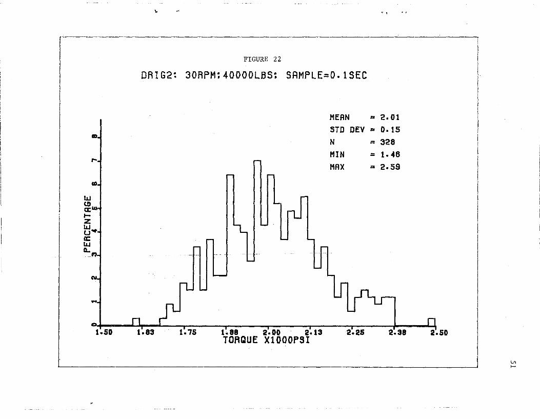
the distributions were plotted and are shown in ~igures 16 through 27. These
figures represent penetration, thrust, torque, a*d RPM for three different
tests; tests varied from 15 to 30 RPH and 20,000:to 40,000 Ibs. thrust. Data
was collected at the rate of 10 data points per ~econd. Total duration of
the tests varied from 30 to 40 seconds. The sha~e of the distributions are·
as expected with the penetration being uniform a4d the other parameters having
normal (bell shaped) form. Variability about thJ means is relatively small I
37

and well within the expected noise limits for the tests. Variation is due
to machine vibration and the electrical/mechanical control system itself.
The most important finding from these tests was the effect of thrust on
cutting performance. At a low thrust of 20,000 lbs., barely any rock was
38
cut as the thrust level was insufficient for individual bits to effectively
penetrate oil shale. Increasing the thrust to 40,000 lbs. dramatically
increased the penetration rate, indicating there is a critical thrust one
must exceed to obtain efficient cutting. Below this critical thrust "GLAZING"
occurs, a phenomenon which results in very little cutting accompanied with
extensive heat build-up on the bits. This is exactly what was observed in
previous field tests, where insufficient machine thrust resulted in glazing
and rapid bit wear. The exact level of this threshold thrust will depend
on the type, shape, cutters, and size of the machine being used. Current
machine thrusting capabilities are considered inadequate, and modifications
in machine weight or in anchoring mechanisms will be required. A more thorough
analysis of individual cutter forces, penetration, and spacing effects should
allow the development of relationships to predict the cutterhead forces
required for efficient cutting for each machine type.
Another encouraging result of the laboratory tests was the excellent
correlation between torque and applied thrust. Figure 28 shows this result
and indicates a correlation coefficient of 0.95.
A test was attempted at 60,000 lbs. of thrust, with dramatic cutting
rates, but torque drive motor power peaks apparently disrupted the computer,
resulting in loss of cutting data. The unit performed well with no damage to
the picks and very little heat build-up. It would appear that as large a
depth of cut as possible is the most effective approach for both optimal
penetration rates and reduced unit costs.
"'

39
TABLE 7
Rotary Cutting Tests Performed:
Test No. 1 - Machine Thrust: 20,000 1bs. , C1;ltterhead RPM: 15
Test No. 2 - Machine Thrust: 40,000 1bs. , Cmtterhead RPM: 15
Test No. 3 - Machine Thrust: 40,000 ,
1bs. , C1.!Itterhead RPM: 30
Test No. 4 - Machine Thrust: 60,000 1bs. , Cutterhead RPN: 30 ,
Test Parameters Neasured:
Thrust
Torque
Penetration
RPN

Machine Thrust: 40,000 Ibs.
Cutterhead RPM: 15
u :--·-·-r~l--r· - I '--I ' i -1--llr-r 1r-- I- -----1+---' -, ..... I
~j~I~-I;I-rl~l~I-J~ ~~j=-tllt~l:i --1-, Ili-I--ll-m .-.. -- ___ Lt= .::::ti 7 +-- I -
:-r--~I:I~-i:~=l---f~i~=-~=l~_ . , r-- -!Il~,--:--~; \- ... L,..~
~IJ~T -=r~L ' I I I I
1~-t~J~tHRP& TI
-i--i-dl-i I ' .. ~
I , .... ,
- i r
, ' --I
•• 1
I ,
i I I....".i.
~ "
FIGURE 14
. .
i _ I.
'(,-~
~
., .

\. ~-,
FIGURE 15
Machine Thrust: 40,000 Ibs.
Cutterhead RPM: 15
. . . l __ ~_ • _I_._.L~-l ___ _ ~,
" ~ . .)
--,'
..,..
......
I I
I I i I I I ! I

Machine Thrust: 40,000 lbs. Cutterhead RPM = 15
Number of Observations: 358 Number of Variables: 4
1.00E-05 1.00E-05
F-level for Inclusion: F-level for Deletion:
Channel
o - Penetration
1 - Thrust
2 - Torque
3 - RPM
Mean
2.4294039E+Ol
3.5574429E+Ol
2. 2614923E+00
1.2637653E+Ol
Chan Vs Chan
( 0)
( 0)
( 0)
( 1)
( 1)
( 2)
( 1)
( 2)
( 3)
( 2)
( 3)
( 3)
TABLE 8
Std. Dev.
1.0158316E+00
1. 40684 77E+OO
2.2926547E-Ol
2. 1844356E+00
CorrelationCoef.
0.028166
0.174427
0.020118
0.382525
-0.095864
-0.419522
SY = 5.9649654E+01
Correlation with Variable 3
0.020118
-0.095864
-0.419522
1.000000
42
t

43
TABLE 9
Machine Thrust: 40,000 lbs. Cutterhead RPM = 30
Number of Observations: 330 Number of Variables: 4 F-level for Inclusion: 1.00E-05 F-level for Deletion: 1.00E-05
Correlation with Channel Mean Std. DejV. Variable 3
o - Penetration 2. 8967804E+01 1. 6071804E.+00 0.013583
1 - Thrust 3. 3341087E+01 1.0813646E+00 -0.135659
2 - Torque 2.0146928E+00 1.5866214E-01 -0.352241
3 - RPM 2.8907360E+01 2. 4413338E+00 1.000000
Chan Vs Chan Correlation Ooef.
( 0) ( 1) -0.172158
( 0) ( 2) 0.008836
( 0) ( 3) 0.013583
( 1) ( 2) 0.488912
( 1) ( 3) -0.135659
( 2) ( 3) -0.352241
SY = 6.6664688E+Ol

TABLE 10
Machine Thrust: 20,000 lbs. Cutterhead RPM = 15
Number of .Observations: Number of Variables: F-level for Inclusion: F-level for Deletion:
Channel·
403 4 1.00E-05 1.00E-05
Mean
0 - Penetra~iort· 3. 1998840E+01
1 - Thrust 1. 7602695E+01 .
2 - Torque 1. 1573719E+00
3 - RPM 1. 4259145E+01
Chan Vs Chan
( 0) ( 1)
( 0) ( 2)
( 0) ( 3)
( 1) ( 2)
( 1) ( 3)
( 2) ( 3)
Std. Dev.
1. 3845161E-Or
3.IQ71839E-Ol
1. 1166510E-01
1. 2307043E+00
Correlation Coef.
-0.336291
-0.557167
0.015920
0.561543
-0.076681
-0.261409
SY = 3.3606434E+01
44
Correlation with , Variable 3
. 0.015920
-0.076681
-0.261409
1.000000

r I
I I
" it" ~I .. Ji.J
FIGURE 16
DRIG1: 15RPM:40000LBS; SAMPlE=O.l SEC.
MEAN = 24.29 STO DEV = 1.02 N = 358
MIN n = 22.24 MAX = 26.07
°1 i 2 3 i ish L 21.00 21.75 2 .50 2 .25 2~.00 2~.75 2 .50 2.25 24
I i i I
I I I I I
I I
I
"'" \JI

r-----I \
I I I I
FIGURE 17
DRIG1: 15RPM:40000LBS: SAMPLE=O.l SEC.
MEAN = 35.47 src DEV = 1.22 N
MIN MAX
= 350 = 31.58 = 41.95
01 I I I Y Y hJ Y, 3i.oo 3G~OO 3tOO 3~.OO 3§.OO 3h.oo S ,
THRUST Xl000LBS
.... ,,~
"
J -I'-0\

I I
I
!
I
I
I
I I !
I I I
....
t'?,
IU (.!) a: tz IU u a:N IU Q..-
\, .. ".. .#
FIGURE 18
DRIG1: 15RPMc40000LBS; SAMPL~=O.l SEC.
2~05 2~20 2~35 TORQUE Xl000PSI
MEAN = 2.25 SrD DEV = 0.21 N
MIN MAX
= 350 = 1.51 = 3.04
I i ,
,j:'
"
I

o o •
o o ~----~------r-----~-----'------~-----r----~' OCD
L-_________________ ,--_____________ ._ ....
48

I
lIJ CD a: tZ lIJ U IE: lIJ
-11..--N
\,
FIGURE 20
DRIG2: 30RPM;40000LBS; SAMPLE=O.l SEC
MEAN :: 28.97 SrD DEV :: 1.61 N = 330
MIN = 25.95 MAX :: 31.91
2'7.75 28.00 3D.25 PENETRATION. IN
"" ,,"-J
3;C.OO
..,. \C

II I t
I I J
I
I I
FIGURE·21
DRIG2: ~OAPM;4000DLBS: SRMPLE=O.l SEC.
MEAN = 33.41 STO DEV = 0.85 N = 328 MIN = 24.19 MAX = 35.10
,
.25 38.00
I "" ~ .• "
\J1 o
I ! i
I I 1 {
I
" " " .
FIGURE 22
DRIG2: 30RPM~40000LBS; SAMPLE=O.lSEC
MEAN = 2.01 STD DEV = 0.15 N = 328
MIN = 1.46 MAX == 2.59
01 II I 'I iii iii I 1
1.50 1.83 1.75 1.88 2.00 2.13 2.25 2.38 2.50 TORQUE Xl000PSI
1
I
I I
I
I I i
I
U1 >-'
I !
I

,;~,--~i~~.:C;,- -,.-
. FIGURE 23
DRIG2: 30RPM:40000LBS: SAMPLE=O.lSEC.
MEAN = 28.93 STD DEV = 2.41 N = 329 MIN = 21.86 MAX = 35.05
32.50
~ ... ·C-\
\.11 N·

i
I
I
I I I
I I
I , !
I I
w t!) a: t-CD, Z' W u a:: weD 0:-'-
..
FIGURE 24
DRIG3: 15RPM;20oboLBS: SAMPL~=O.lSEG
MEAN = 32.00 STD DEV ... 0.14 N = 403 MIN = 31.54 MAX = 32.32
". , n.,.
32.50
Ln W
J

II ....
FIGURE 25
DAI G3~ 1 SRPM; 20000LBS; SAMPLE=O. 1 SEC
MEAN = 17.58
STD DEV = 0.25 N = 393 MIN = 16.29 MAX = 19.22
, ~ ~ ..:..~,'
lJ1 -I>-

I-I
... . , "
"--------------------------""-----------------,
FIGURE 26
DR1G3: 15 RPM:20000LBS; SAMPLE=O.1 SEC
MEAN = 1.15
STD DEV = 0.09 N = 390 MIN = 0.96
MAX = 1.68
&:I I I
0.80 i 0;'88
Lr1 Lr1
I
I I I
I I I

I FIGURE 27 .
DAIG3: 15APM:20000LBS; SRMPLE=O.lSEC
MEAN .. 14.25 STD DEV .. 1.22 N .. 402 MIN .. 10.99 MAX .. 17.58
13.13 1'1.00 1'1.88 15.75 RPM
V1 ~)
'"
, '" ¥ " \.-4

.... C/)
o o · C')
." ~ •
N
o C')
• N
Q..." Om O. 0-
..... ".~ ~.-" "'--~
FIGURE 28
THRUST VS TORQUE FOR OIL SHALE
~ ~ ~ +~ +
SLOPE = 0.059 YO = 0.109 C COEF = 0.949
C\b.oo 1~.25 2h.50 25.75 2~.OO 3h.25 35.50 3b.75 4h.oo THRUST X1000LBS
V1
"

IV. ECONOMIC EVALUATION
Objective
Mechanical boring machines are generally not used routinely in hard rock
mining operations due to the initial capital investment and the lack of
experience and acceptance. Oil shale will offer a good opportunity to
show the economic potential of mechanical excavation. The objective of the
economic evaluation was to develop preliminary evaluation criteria for compar
ing a mechanical excavation system to conventional drill and blast methods.
This work is part of a continuing effort to improve the understanding of
how mechanical excavation systems behave in a mining environment. The
58
greatest potential for mechanical fragmentation machines will be in providing
low cost mine access drifts from the production areas to the surface facilities.
Cost of providing development openings in oil shale will require the
knowledge of many machine/rock parameters such as rock type, machine power,
penetration rate, cutter life, maintenance schedule, etc. Capital investment,
labor requirements, and project scheduling will all play an important role
in defining the economics of the overall project.
Knowledge of the cost sensitivity of different project parameters
will improve the overall success of any particular tunneling project if
this information is incorporated into an effective management plan. Acknow
ledging the problems of defining reliable cost estimates for an untested
machine in oil shale, this section gives some general guidelines for anticipated
trends and problems plus the software needed to quickly reexamine the economics
as new technology evolves.
Introduction
Despite the many advantages of using tunnel boring machines (TBM),
drill and blast is normally preferred in most mining applications. The
trade~offs between the two systems of rock fragmentation are numerous,

59
highly interactive, and tedious to compute manually. As part of this study,
an attempt was made to integrate the theoretical equations for predicting
the performance of a tunnel boring machine (TBM) with the necessary economic
parameters for aiding in decision making. Of particular interest is the
development of a software package developed for a desk top computer system
enabling an individual to interactively change problem parameters quickly to
learn the relative importance of user selected parameters. Graphic options
also allow the engineer to quickly plot desired results. All the programs
and software discussed in this report can be fully implemented on a micro-
computer.
Several mechanical fragmentation models are available for implementation
on large main frame computers. Some of the models are quite complex and
detailed. The primary goal of the EMI cost model was to develop a model which
could integrate the design parameters of the tunnel boring machine with the
principle factors controlling the costs. Detail was of less importance than
simplicity. No attempt was made to integrate the fragmentation system with,
for example, the materials handling or ground sQPport systems. As most openings
in oil shale will be temporary in nature and due to the relative competence
of the oil shale, the cost of ground support will be smaller than fragmenting
the rock. In any case, the cost of ground support and material handling will
be higher for a drill and blast system compared to mechanical fragmentation.
No two mining projects can be compared directly because of the large
number of factors which must be considered in the design stages. However,
the universal criteria used for comparative purposes between mining projects
is normally rate of advance or cost. Such factors as labor costs, labor
productivity, geologic uniqueness, and political environment will, at times,
make even comparison of costs and advance rates meaningless.
The actual conditions existing at a particular site are the criteria
which will dictate the machine design, rate of advance, and the economic

60
consequences. Site factors may be classified as follows:
rock characteristics and properties,
g.eologic conditions,
tunnel geometry.
Predicting the maximum rate of advance of a tunnel boring machine will
depend upon the following machine parameters:
machine thrust,
machine torque,
machine RPM,
cutter type and geometry,
cutterhead geometry,
cutter wear.
The cost of using a mechanical boring machine will depend upon how a
machine functions in the geologic environment and what it costs in terms
of labor, material, and equipment. No two operations will ever be equivalent,
however, the factors which determine the system's productivity will be similar
from Qne job to another. The principal factors that determine the overall
project costs are:
time required to complete project,
capital investment,
material and labor costs.
There is considerably more to driving entries with a tunnel boring
machine than measuring a few rock properties, designing a machine, defining
a few costs, and letting a computer program define the "best way." The
intent of the technique discussed herein is not to replace the engineer, but
rather to help him or her to be more productive by being able to quickly
calculate alternative designs in a shorter time frame.
In selecting a tunnel boring machine not all design and cost factors are
of equal importance, therefore engineering design efforts should be proportional

61
to their potential reduction in cost or improvement in benefit.
Computer Models
as part of this program, a series of computer programs have·been developed
for evaluating the ec.onomics of various mining subsystems, including:
1) fragmentation - drilling and blasting;
2) fragmentation- tunnel boring machine with disk cutters;
3) material handling - cyclical;
4) ground support;
5) ventilation;
6) subsystems design.
All of these programs are designed to stand alone, however, they may be used
collectively to evaluate a total system. The tunnel boring machine fragmenta-
tion program only looks at the actual rock breakage and does not include
the materials handling, ventilation, ground control and support subsystem.
The basic premise upon which the economic ~ost/performance was derived
is the machine-rock performance equations devel~ped at the Earth Mechanics
Institute based on previous research in rock cutting. One may choose to
ignore the predictive equations and enter directly a penetration rate and
machine horsepower, however, this does eliminate one of the most important
design portions of the model. Given in Appendi¥ A at the conclusion of
this report are the equations used for calculat~ng penetration and horsepower
used in this discussion.
Following is a list of the equations used in the economic model itself:
Project life
T TL
p ~< RPM * C1 * HR * A ,~ U + SU
where
T = project life, (days)
TL tunnel length, (length)
SU time to set up machine, ,(days)

p = penetration rate, Length/rpm)
RPM = revolutions per minute
Cl conversion factor
HR hours worked/day
A = TBM availability
U = TBM utilization
The product A*U*lOO should equal percent time machine is at maximum thrust
Labor cost
LC = L * HR * T
where
LC = total labor cost for project
L = labor cost/hr
Material costs
where
and
where
and
MT = CT + PT + Ml * TL + M2 * T * HR * A * U
MT total cost of meterials for project
CT cutter cost, ($)
PT power costs ($)
Ml = cost of materials, ($/length)
M2 cost of materials ($!TBM) (cutting) hours
CT = CN * CC * T * HR * A * U CL
CC cost of one cutter disk ($)
CL cutter life (hours)
PT = HP * C2 * PC * T * HR * A * U EF
62
• ,.

where
HP horsepower
C2 conversion factor
PC power cost ($/kwh)
EF motor efficiency
Equipment costs
TBMC = total cost of the machine :for the project
Project cost per unit length:
TCPF =
where
TBMC + MT + 1T T1
TCPF = total project cost per unit length
Problem Sensitivity
Ability to change and rerun a problek quickly gives one the opportunity
to investigate how small or large changes in specific parameters will affect
the overall results. It should be remembered that any two projects will vary
significantly from what is presented here; thus, generalizations should not
be concluded from what is presented herein. All of the values used in the
63
examples presented in this report are taken to be realistic in 1982 US dollars.
They do not represent any particular project andiare generated only for
illustration purposes used in this report.
Rock properties and penetration
Figure 29 is a plot of the thrust versus penetration with a 10% variation
in rock strength properties. Figure 30 is a plot of the horsepower requirements
for a desired penetration. Of importance is the sensitivity of the penetration
rate to variations in rock strengths. If, for example, in the problem given
in Figure 1 at 200,000 lbs. of thrust, the rock strength drops 10% from
30,000 psi to 27,000 psi, then the penetration r~te will increase from 2.30
ft/hr to 2.43 ft/hr. This represents an increase in penetration of 20%. It
may be concluded that a 1% decrease in rock stre~gth will yield a 2% increase

a: ::r:
" I-I..L
W(Y') Ier: 0::
:z: o ........ ru Ia: a: Iw :z:
FIGURE29: PENETRATION RATE VS MACHINE THRUST
COMPRESSIVE STRENGTH (PSI) 30000
SHEAR STRENGTH (PSI 1 3000
CUTTERHEAO DIA. (IN) 84
NUMBER CUTTERS 16
CUTTER ANGLE (DEGREES) 90
CUTTER DIAMETER (IN) 12
CUTTERHEAD (RPM) 9
ROCK VARIATION (/0) 10
01 ~ o 40 80 120 160 200
MACHINE THRUST(LBS) ~103 280 240
,.;'" • r ..
320
'" .0-

a: w ::s: C)
IL
a 00 C\J
a CD -a
wC\J cnee C)
:c o 0:00 WOO
:c a: w lt::;)00 w~
, '. i... ... ~ i
FIG U R E 30.: H. P. V 5 PEN E T R R TID N R R T E
COMPRESSIVE STRENGTH (PSI) 30000
SHEAR STRENGTH (PSI) 3000
CUTTERHEAD DIA. (IN) 84
NUMBER CUTTERS 16
CUTTER ANGLE (DEGREES) 90
CUTTER DIAMETER (IN) 12
CUTTERHEAD (RPM) 9
ROCK VARIATION (X) 10
00;1---------,---------,---------,---------,----____ -, ________ -, ________ -, ________ -. 1.50 2.50 3.50 4.50 5~50 6~50 7.50 8.50
PENETRATION RATE (FT/HR) '" V1

in any calculation for the problem as defined in Figure29. It should be
obvious that care should be exercised when defining rock strength using the
computer model.
Appendix B gives a set of computer plots for a variation of machine
configurations.
Problem parameters
To illustrate how the model was used, Table 11 gives a set of user
defined parameters used in this report to show how the various problem
parameters interact one with another.
Following are the basic assumptions used to compile the data used in
Table ~l. In the following the abbreviation D & B is used to denote drilling
and blasting.
Basic conditions:
only the fragmentation subsystem is considered, costs d9 not
include:
material handling
ground support
support services
overhead, amortization, etc.
Tunnel definition:
length:
Shape:
geology:
Rock properties:
20,000 ft.
TBM - 12 ft. diameter - circular D&B - 10.6xl0.6 ft. -~rectangular
ideal
rock density 2.3
compressive strength: 15,000 psi
shear strength: 1,500 psi
66
•
I
i I ~

Ta.b lE!' 11
*** INPUT **1
__ * GENERAL PARAMETERS '" ROCK DENSITY HOURS/DAY DAYS/YEAR TUNNEL LENGTH
2.30 TUNNEL DIAMETER <IN) 24. 00 COl'lPRESS STREN (PSI) 255.0 SHEAR STRENGTH (PSI)
(FTl 20000 SET UP TIME
*** I"IACHINE CUTTERS TOTAL NUI"IBER OF
CUTTER ANGLE DIAMETER OF CUTTER RPt'j
PARAMETERS 1** 24 THRUST
MOTOR EFFICIENCY
LABOR CUTTER MATERIAL
<DEG) (IN)
*** COST ($/HR) ($/EA) ($/FT>
90 UTILIZATION 17.5 AVAILABILITY 8.0 CUTTER LIFE
0.90 MOTOR HOURS
PARAMETERS *** 210.00 325.00
7.20
POWER I"IACHINE t1ATERIAL
*** RESULTS 1** LABOR I"IATERIAL
$/FT 33.9 18.3 $/HR 210.0 113.5
TOTAL 677041 366001
ADVANCE FT/HR MAXIMUM ADVANCE FT/HR AVERAGE DAYS TO COMPLETE PROJECT TOTAL TONS TOTAL MACHINE HOURS /. MACHINE UTILIZED
Conversions
EQUIPMENT
105.0 651.4
2100000
16.6 8.0
134.3 162317
1202 20.0
1 LB force = 4.45 Newtons 1 PSI stress = 6400 pascals 1 IN length = 2.54 centimeters 1 FT length = 0.305 meters
<DAYS)
(LBS)
(HR)
($/KW) ($)
($/HR)
TOTAL
157.2 974.9
3143040
67
144.0 15000
1500 30.0
960000 .60 .80 500
6000
0.14 2100000
0.00

Machine characteristics:
TBM:
D&B:
Costs:
24 disk cutters 17.5 in. cutter diameter 90 degree cutting angle on cutter 960,000 lb. machine thrust 8 rpm 500 hours of cutter life 0.8 machine availability 0.6 machine util:ization
1.5 powder factor 7.2 ft. depth of round 7 hours to complete cycle 0.8 equipment availability 0.8 equipment utilization
equipment:
TBM - $2,100,000 (TBM only)
D&B - $300,000 (drill jumbo)
Materials:
Labor:
TBM - $325 per cutter - $.14 per KWH - $7.20 per ft., misc.
D&B - powder $0.50 per lb. - $7.20 per ft., misc.
TBM - $40/hour/man - 5 men for 15 shifts production - 9 men for 1 shift maintenance
D&B - $40/hour/man - 2.5 men for production and maintenance
Equipment utilization
The importance of the rock strength upon penetration rate is perhaps
better illustrated in Figure 31. Figure 31 shows the influence that rock
strength of 10,000 psi, the penetration rate decreases rapidly. As is evident
68

. . o o o ....... 0 XC")
. :z: I,LJ a: J<nlJ)
. 0-L a u
-
THRUST = 960000 LBS
NUMBER: CUTTERS = 24 ,
TBM DIAMETER = 12 FT
+ 1007. UTIL THEOR~TICAL x 507. UTIL THEORE~ICAL o ACTUAL
O+---------------~--~-------~~I--------------~I o 10 20 30 PENETRRTION. FT/HR
FIGURE31: COMPARISON OF THEO~ETICAL PENETRATION
RATES VERSUS ROCK STRENGTH
69

in this figure, the actual rates achieved under field conditions are
approximately only 40% of the estimated theoretical penetration rates.
This is not a totally unexpected result, because the actual time a machine
is cutting is normally less than 50% of the time during a project life. Thus,
a .05 point gain in machine utilization may be directly translated into a
greater than 5% increase in rate of advance for most operations (especially
if actual cutting time is less than 50%). For example, increasing machine
cutting time from 25% to 30% will actually shorten the time of the tunneling
project by 20%.
It should be remembered that these curves will be valid indicators
only under the best of conditions. For example, with decreased rock strength
ground control problems will most likely increase and become a limiting factor
to the rate at which an opening can be successfully advanced. Rate at which
material can be removed from the TBM must also be considered. Other environ
mental factors such as water, temperature, gases, etc. can pose problems
which can significantly affect the advance rate of a mechanical excavator.
TBM versus conventional
Another area of concern to many decision makers is the trade-offs
70
between tunnel boring machines and conventional drill 'and blasting. Figure32
shows the cost per meter of driving a tunnel of varied lengths using the two
methods. All factors being equal (this is not normally the situation) for
tunnels of less than 20,000 ft. the actual cost per meter of advance is much
cheaper using conventional drilling and blasting. As the length of excavation
or tunneling increases, as would be true in a mining environment, TBMs are
more cost effective. This is primarily due to the relationship between
capital investment and operating costs for the two alternatives. This fact
is graphically shown in Figure 33. If the cost of capital is high, one may
wish to take what is presented here one step further by considering the cash
flow.

•
lLL ....... -\f't
Ien a u
00 (D + TUNNEL BORING MRCHINE
x DRILL RND BLRST
o 20 40 60 TUNNEL LENGTH. FT Xi00G
FIGURE32: COST COMPRRISON FOR CONVENTIONRL
MINING RND TUNNEL BORING MRCHNE (TBM J
71

I-en a u
--.J a: I-a
o o
-
1-0 ,In 1-0 en CJ U
--.J ce I-........ a..-ce u
o <::>
72
+ EQUIPMENT/TOTAL COST MECHANICAL x EQUIPMENT/TOTAL COST CONVENTIONAL
.+-------------.-------------.-------~----. o 0 20 40 60
TUNNEL LENGTH. FT XIOOG
FIGURE 33: COST SENSITIVITY COMPRRISON OF
CONVENTIONRL VERSUS MECHRNICRL FRRGMENTRTION
• ·
• ·

Parameter sensitivity
If each variable is allowed to change by a fixed quantity and the
problem rerun each time, we may get an idea of those factors which have the
greatest impact on the overall results. Using the parameter values given
in this report, a 10% parameter change (taken one at a time) will yield a
reduction in overall project cost between a maximum of $210,000 and a minimum
of $1,600. Ranking the parameters from most important to least impact on
the results gives the plot shown in Figure 34. As illustrated by this example,
more effort should be allocated to the cost assumed for the tunnel boring
machine itself compared to, for example, the rock properties. Relatively
speaking, the cost of the tunnel boring machine is 4.47 times as important as
the rock properties.
Verification of Results
Verification of the penetration equation has been tested on red granite,
marble, and limestone in the laboratory and under field conditions and agree
ment has been between 5 to 10% between predicted and actual. Expected
correlation for the costs then should be within plus or minus 20% depending
upon the experience of the user. Predicting costs is an art. How close a
prediction will be to reality for a particular prbject will depend upon the
validity of the assumptions.
Appendix C contains a statistical evaluation of some data collected by
RMC, Inc. In a 1971 study titled "Tunneling Cost Analysis," of interest is
the large variation in costs between projects. However, there is a definite
relationship between the rock properties, tunnel ,length, tunnel diameter, and
costs. Interpretation of results is left to the reader.
Summary
The basic economic model discussed in this report is an inexpensive tool
based upon sound engineering for testing alternative machine designs in an
73

FIGURE34: RELATIVE SENSITIVITY OF PROBLEM PARAMETERS
FACTORS RANKED BY RELATIVE SENSITIVITY
REPRESENTS lOX CHANGE IN PARAMETER
z .~~ ~ ~ w "'~"" _" ., ,:' ··0·· 's <'" ,v >: "'u ,',' 'vv 'v '" 0 d! LU '" "" 0""" <". > .,. OJ .,., ,." i!!." ~~" 00 ···z·.·. ",v </" <". ",- ','~,,', i!! ~,,~ "iv" <L "~or"~"~ <," ,~ '> "'~ *' ~" ::E ",u"" <, , ,,'v R) <c ",'_
~C:> ~ <, ~4,.
v'0 <v~ 'V~ ~" ..... v'" ~ ,-,'V ~~ n..' '\,~<v ~ ",g;",\"""""" <c'" ,,<' S 'I,'> " l" I
if)
o u
~«; «'- ~ ~~ ~<t.; 'V~ I?" ~ Q\S ... 'V-<"':' .'}.~-:S
,>"" '\ I?\ .~ ~ v
PROBLEM PARAMETER
• .. • l"
., ---- - --~-".---~
...,
."..

75
oil shale environment. In the design stages, these programs can give insight
into where the major efforts are going to have to be placed to improve advance
rates and/or reduce costs. Comparison of several different possible changes
in an existing mining operation can quickly be evaluated on a computer to
rank the alternative changes based upon their potential economic benefit.
Economics do suggest that TBMs can provide a iesser cost fragmentation
system when compared to drilling and blasting in oil shale. There are still
a lot of unknowns, such as the economies of scale to be gained for large
oil shale mines, the wear of cutter disks in oil s~ale, the machine utilization
in a working environment, etc.

V. CONCLUSIONS
A number of conclusions can be drawn from this investigation relative
to mechanical excavation applied to oil shale.
1. The physical properties of oil shale are fairly well understood. As
76
applies to mechanical excavation, the range of strengths observed places oil
shale in the region of crossover between suitability for drag bit cutters and
the requirement for roller cutters. Also the variability in physical properties
over an anticipated mining section demand that an oil shale excavator be
able to operate c:v~r the wide range of rock properties present. An under
standing of the rock physical properties also means that existing performance
prediction models can be used effectively to evaluate mechanical excavation
systems and estimate their production rates.
2. Linear cutting tests were effective in determining the forces required to
efficiently cut oil shale. The effects of cutting direction were dramatic and
must be considered in estimating production and in machine design. The
ease of cutting in a direction perpendicular to the bedding or varve structure
suggests a machine designed to take advantage of this directional property
would represent a significant improvement in efficiency. from these preliminary
tests it appears drag bit type cutters are more efficient in terms of fragment
size and minimum fines. Disc cutting has the advantage of le~s dust and longer
cutter life.
3. Rotary Cutting tests in oil shale using a Dosco boom head with long
shank conical bits demonstrated that an excavation system can be successfully
evaluated in the laboratory. Excellent correlations between machine parameters
and performance were observed. The laboratory tests support the conclusion
that a minimum thrust or force per cutter is required for effective cutting.
This is borne out by experiences in the field where roadheader type machines
have been tried in oil shale. Generally the light weight of the machines have

77
prevented sufficient thrust to the cutters to allow efficient cutting. This
results in glazing of the oil shale, excess heat buildup and rapid wear of the
cutters. It is evident that as deep a cut as possible needs to be attained
resulting in higher production and lower cutter costs.
4. An evaluation of mechanical excavation applied to oil shale revealed a
significant need and many potential benefits. It ~s felt there are two
distinct areas of. applicability, development and production mining, which must
be considered separately. Mechanical excavation a1'so offers potential benefits
to an open pit oil shale mining operation.
Full-face machines offer higher production rates, but lack of mobility
may restrict their application only to development. Partial-face machines,
such as roadheaders, are generally very maneuverab1fe but may be limited in
attainable production rates. New machine concepts being developed should
combine the efficiency of a full-face machine with the flexibility and
selective mining capability of partial-face machin~s.
A technique was developed for ranking machine capabilities and pe.rformance
to determine the relative applicability to oil shale mining. Considering cur
rent technology, tunnel boring machines, slot machines, and rectangular boring
machines appear to be best suited for the long dri-yes envisaged for development
work. In terms of immediate application, full-face machines using disc cutters
remain the best choice because of their high produ~tion rates and proven concept.
For future applications in development work, full-face mach.ines still remain
a good choice, but anticipated improvements in machine design and size also
make the boom-type miner attractive for development. For a production
application using existing technology, boom-type miners, continuous miners,
and the mobile miner appeared most favorable. These machines ranked only
marginally above drill and blast, suggesting the pGlssibility that a synergistic
combination of mechanical excavation with drill ami' blast may, for the present,
be an optimum approach. The future potential for riIechanical excavation in
-_~_ ~ ____ .~_~ ____ •• _,._,... _____ ~ __ .~u _ ________________ _

78
production is excellent. As larger, more specific machines are developed for
production, mechanical excavation is expected to dominate. Boom-type miners,
continuous miners, and the mobile miner have the best potential, mainly
because of mobility and flexibility. Two full-face machines, the rectangular
boring machine and the slot machine, show considerable potential as mining
systems adapt to take advantage of their high production rates and low costs,
while compensating for their reduced mobility.

79
VI. RECOMMENDATIONS
The conclusions of this study are felt to be valid for the informa-
tion available from literature review and the results of laboratory
cutting tests. Yet most of the machines evaluated have never cut oil
shale. It is therefore, felt that cutting performance of each system
I
evaluated should be verified through additional laporatory tests of
various cutters and cutting patterns before any final conclusions are
drawn as to the best mechanical excavation systems; to pursue for their
potential application to oil shale mining. Toward this end, the fol-
lowing areas are recommended for further research:,
*1. Linear cutting test of various cutters ati different spacing
and penetrations at several bedding orie~tations.
*2. Full scale laboratory tests on drill rig and the rotary cutting
machine to evaluate cutterhead design (shape, spacing, muck
handling, temperature, wear, power, forces, etc.).
3. Determining design principles for optimu~ performances.
4. Estimate productivity and applicability.
5. Economic comparisons.
6. New mine design approaches to take advantage of the benefits
Ii
of mechanical excavation.
t 7. Investigate application of water jets or other assisting mechanisms.
8. Total system evaluation to include cutting, material handling,
retorting, disposal, backfill, roof and pillar stability and
overall economics.
*These equipment are currently available at the Earth Mechanics Institute,
Colorado School of Mines.

VII. REFERENCES
l. Brockway, P. E., 1982, "Tunnel Boring }fachine or Drill and Blast," 14th Canadian Rock Mechanics Symposium, 1982.
2. DesLauriers, John A., 1981, "Machine Mining for Rock Tunnels," 1981 RETC Proceedings, Vol. 1.
3. Hibbard, R. R., et aI, 1971, "Hardrock Tunneling System Evaluation and Computer Simulation," PB-733667, l30 pp.
4. Kennedy, E.IR., 1981, "Tunnel Boring Machine Application - the Kerchoff 2 Underground Hydroelectric Power Plant," Robbins Co.
5. McFeat-Smith, Ian, and Tarkoy, Peter J., 1979, "Assessment of Tunnel Boring Machine Performance," Tunnels and Tunnelling.
6. Ozdemir, Levent, 1973, "Mechanical Tunnel Boring Prediction and Machine Design," National Science F,oundation, 313 pp.
7. Sharp, W. R., and Douglas, E. L., 1982, "Development of an Interactive Graphics Station for Mining Applications," 17th APCOM Symposium, AIME, pp. 327:-33l.
8. Spittel, 1. A. and Wilyard, J. C., 1971, "Tunneling Cost Analysis," Grant No. DOT-FR-00040, for U. S. Department of Transportation, NTIS.
9.' Wheby, F. T., and Cikanek, E. M., 1973, "A Computer Program for Estimating Costs of Tunneling (COSTUN)," PB-228740, October, for U.S. Dept. of Transportation, NTIS, Virginia.
80
" i
•

81
APPENDIX A
Pictures of laboratory cutting tests in oil shale


A-I
•
Large Linear Cutting Machine Used for Testing Conical Bit and Disc Cutter in Oil Shale. !

A-2
Conical Bit Mounted on Linear Cutter.

A-3
r
Conical Bit Testing for Oil Shale Bedding Direction No.1.

A-4
•
Chips Produced from Cutting in Bedding Direction No.1.

A-5
. .
Chips Produced from Conical Bit Tests for Bedding Direction No. 1

A-6
Disc Cutter Testing for Bedding Direction No.1.

Peru!,Trctriort _ 35
..::::>pacl"n;:t /.50
~t;-gj/c~/Or +0 .£:3e'ddln ~ p/an~
Rock Surface Produced by Conical Bit in Bedding Direction No. 2
A-7

A-8
Typical Chips for Bedding Direction No., 2 (Conical Bit)
, .
I I
, t

A-9
Disc Cutter Testing in Bedding Direction No. 2
--- ~ -~~~~-----

A-IO
Typical Chips for Bedding Direction No. 2 (Disc Cutter)

A-ll ;...:,'
:
Conical Bit Testing for Bedding Directiom No. 3
.--~----~------

A-12
Rock Surface for Bedding Direction No. 2 (Conical Bit)

A-13
:
Laboratory Drilling Rig Used for Testing Doseo Roadheader Cutting Head.

A-14
Oil Shale Sample Placed on the Drill Rig.

:
-------- -"------""----"--~
""".,. iW""'~
"~"i""i"""""".--ci"!4,y1""'
I
"." ""
The Roadheader Cutting Head with Coni~al Bits.
A-I5

Operation of Roadheader Cutting Head in Oil Shale.
,
A-16
• .

..
View of Rock Surface Created by the Roadheader Cutting Head Dressed with Conical Bits.
A-17

, ,
I· .
I, • I ~
! i
". I, t
I l
,
1 r ~ 1
I . I
I
I I I i 1

-.
APPENDIX B
The theoretical relationship for calculating the: penetration per revolution for a sharp disc cutter!.

",

;
The theoretical relationship for calculatirg the penetration per B-1 revolution for a sharp disc cutter based upon work done at the Earth Mechauics Institute, Colorado School of Mines, is as follows:
p = t 2 = (X + y)2
where t X + Y, and
X = [_ E. + jb2
+ a3 J 1/3
2 . 4 27
Y = t ~ _Jb2
+ a3
] 1/3 2 4 27
a = 2'rs Dl/2 tana/2 !:.. C - 4 Ttana/2 3
; VF b = .".~---'-"----.-
.~ C - 4 Ttana/2] Dl/2 tana/2
where definition of this variable is as follows:
VF = vertical force on the cutter (force) C = rock uniaxial compressive strength (stress) T = rock unconfined shear strength (stress) D = cutter diameter (length) a = cutter included edge angle (degrees) s = spacing of cuts (length) p = cutter penetration (length)
I The theoretical equation used to calculate ,horsepower is expressed as follows:
HP = TQ * RPl1 * 2 * 11 / C3
where
and
TQ RF *CN*TD-RF VF* tanS
(1 2 tanS = - cos 1)
~ - sin~os¢
(R -R P). ~ = ArcCos
/ C4
R CD/2
where
HP C3 TQ RF CN TD= C4
tan S = R =
CD= RPM =
horsepower cOllversion factor torque (lel~th-force) rolling force (force) number of cutters diameter of cutterhead (length) conversion factor cutting coefficient radius of cutterhead (length) cutterhead diameter (length) revolution per minute
---------~--~-~------"-------~---------------~-- --- ------- ---------
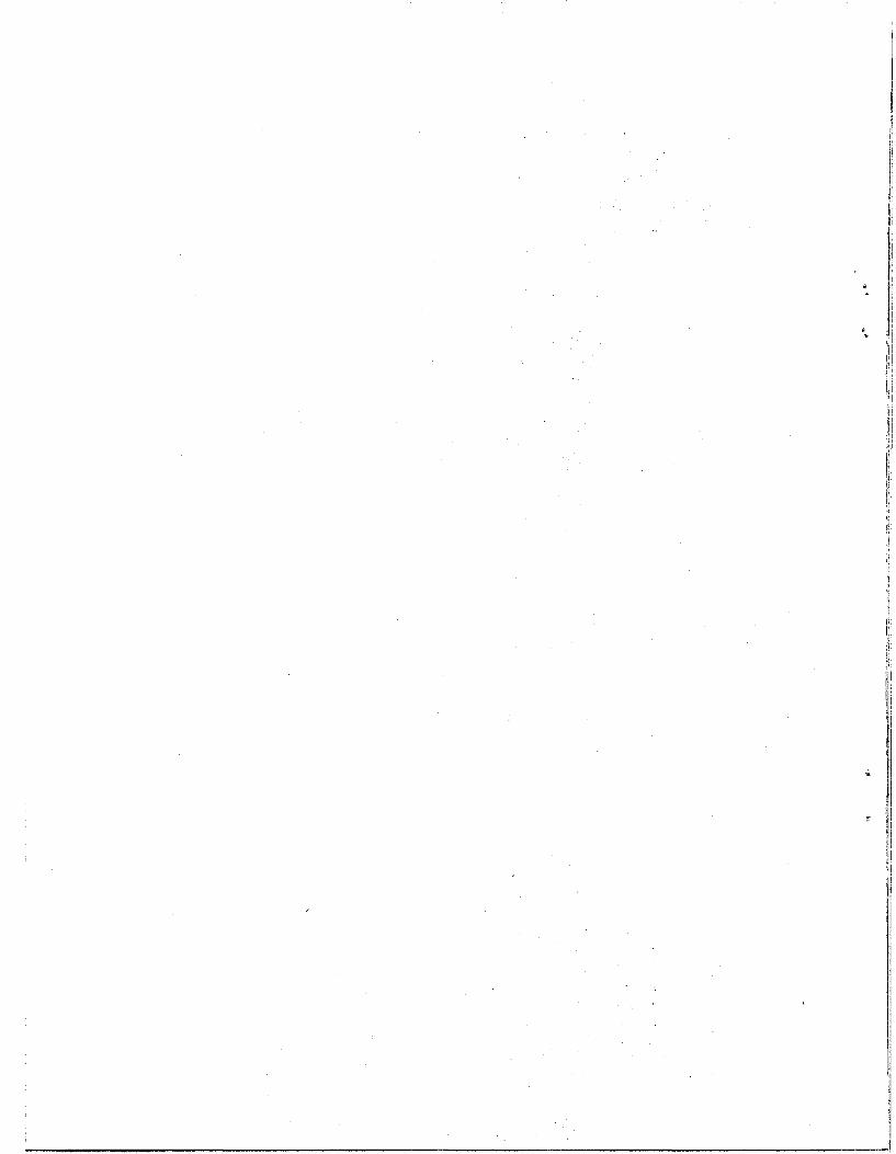
'Ii
i
__ ~ ___ I

APPENDIX C C-1
Penetration vs Machine Thrust for Varied Machine/Rock Parameters:
Machine Number Cutter Cutter Rock Strength Diameter (ft) Cutters Angle Diameter RPM Compressive Shear (psi)
C-1 10 15 90 15 8 10 ,000 1,666 ,
C-2 10 15 . 90 15 8 15,000 2,500
. C-3 , 10 15 90 15 8 20,000 3,333
C-4 20 30 90 15 5 10,000 1,666
C-5 20 30 90 15 5 15,000 2,500
C-6 20 30 90 15 5 20,000 3,333
C-7 10 15 90 15 8 10, 000 2,000
C-8 10 15 90 15 8 10,000 2,500
C-9 10 15 90 15 8 10,000 3,000
C-lO 10 15 90 15 8 10,000 3,333
C-ll 10 15 90 15 8 15,000 2,500
C-12 10 30 90 15 8 15,000 2,500
C-13 10 15 75 15 8 15,000 2,500
C-14 10 30 75 15 8 15,000 2,500
C-15 40 60 90 15 3 10 ,000 1,650

~ ... _~~O_ _~:i."--~·~·~-l>'",""",,,~_",,,,,,",,,,,,,-__ '_' ____ " '-'"
a: :c "-l-LL
z o
PENETRRTION RRTE VS MRCHINE THRUST
II) COMPRESSIVE STRENGTH (PSI) 10000 .... SHEAR STRENGTH (PSI) 1666
CUTTERHEAD DIA. (IN) 120
NUMBER CUTTERS 15
CUTTER ANGLE (DEGREES) 90
CUTTERHEAD DIAMETER (IN) " 15
CUTTERHEAD (RPM) 8
O,I--------~--------_r--------_r--------_r--------._--~----._--------._------__, 162 225 287 350
MRCHINE THRU5T(LBS)
" "'
537
.,'to I"
600 (""') I
N
.~,~---.. ,,~--

lJ') ......
C\J .--.. --c
a: :c ........ ~ LL
wen ~
a: a::: z: D ....... c.o ~ a: a: ~ w Z W(,<") D-
~l. ".,
PEN E T R.R T ION ART E V 5 MR CH I NET H AU 5 T
COMPRESSIVE STRENGTH (PSI) 15000
SHEAR STRENGTH (PSI) 2500
CUTTERHEAO OIA. (IN)" 120
NUMBER CUTTERS
CUTTER ANGLE (DEGREES)
CUTTERHEAO 0 I AMETER (I N )
CUTTERHERO (RPM)
15
90
15
8
O+I--------~------~--------_r--------r_------_r--------,_------_r------__, 537 600 225 287 350 412
MRCHINE THRUST! LB5) ~103 475 100
'!
! I i
zJ

~~i ::c ........ l-LL
z o ...... co IeI: a: IW Z WC') D-
I
PENETRRTION RRTE VS MRCHINE THRUST
COKPRESSIVE STRENGTH (PSI J 20000
SHEAR STRENGTH (PSI J 3333
CUTTERHEAO DIR. (IN) 120
NUMBER CUTTERS 15
CUTTER ANGLE (OEGREES) 90
CUTTERHERO DIRMETER (IN) 15
CUTTERHERO (RPM) 8
ch -=== 100 162 225 287 350 600 MACHINE THRU5T!LBS)
.;. ~)r, -II ,. •
.,,;;;:"-,"'==~=----="" .... - ---.-----~
(") I ~

Ln ....
C\.JI ~ .... a:: I "'-l-LL
z: o H-(O--
Ia: a:: IW z: We<) CL
" ~'t ., "
PENETRRTION RRTEVS MRCHINE THRUST
COMPRESS I VE STRENGTH (PS I ) 10000
SHEAR STRENGTH (PSI) 1666
CUTTERHERD DIA. (IN) 240
NUMBER CUTTERS 30
CUTTER ANGLE (DEGREES) 90
CUTTERHEAD DIAMETER (IN) 15
CUTTERHERD (RPM) 5
o~ 10 37 51 65 106
MACHINE THRUST(LBS) 120
n I
U1

U1 ....
~~1 ::c "'-l-LL
z o -co Ia: a: IW Z W('t) 0....
PENETRRTION RRTE V5 MRCHINE THRU5T
COMPRESS I VE STRENGTH (PS I ) 15000
SHEAR STRENGTH (PSI) 2500
CUTTERHEAD DIA. (IN) 240
NUMBER CUTTERS 30
CUTTER ANGLE (DEGREES) 90
CUTTERHEAD DIAMETER ( IN) 15
CUTTERHEAD (RPM) 5
o I ====:== '120 10 24 92 106 37 51 65 79 MRCHINE THRU5T(LB5) ~10+
~ ," ,'"
("") I
CTI

If)
-<-
C\J ~ ...... -a: ::r::
" l-LL
U-J0l_ I-a: a: z o ....... CD_
I-0: a: IW Z U-J C'"l_ 0...
,. ~ "',1. ~ •
PENETRRTION RRTE V5 MRCHINE THRUST
COMPRESSIVE STRENGTH (PSI)
SHEAR STRENGTH (PSI)
CUTTERHEAD OIA. (IN)
NUMBER CUTTERS
CUTTER ANGLE (DEGREES)
CUTTERHEAD 0 I AMETER (I N )
CUTTERHEAD (RPM J
20000
3333
240
30
90
15
5
01 , , ,=:=, , , , 10 24 37 51 65 79 92 106 120
MRCHINE THRU5T(LBS) ~104 (""') I
"-J
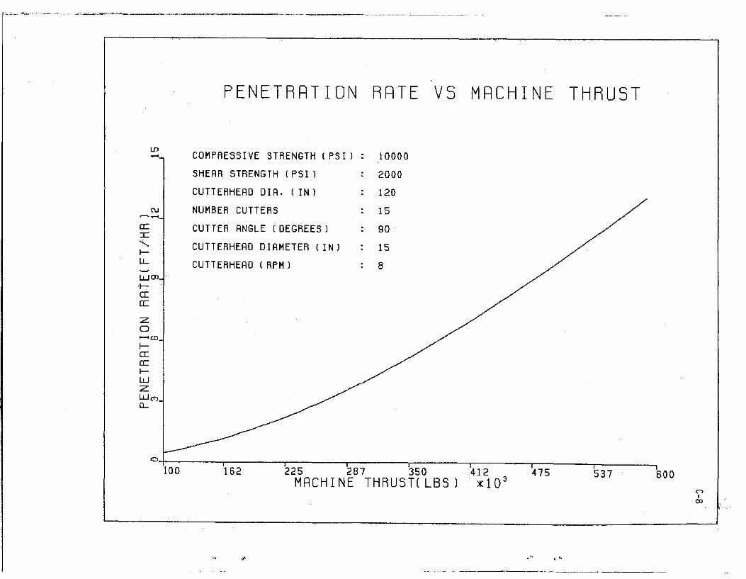
I.J') .......
~~1 ..:..... ~ l.J...
z: o ...... (0
~ a: a: ~ w z W(V) 0-
PENETRRTION RRTE VS MRCHINE THRUST
COMPRESSIVE STRENGTH (PSI) 10000
SHEAR STRENGTH (PSI) 2000
CUTTERHEAD DIA. (IN) 120
NUMBER CUTTERS 15
CUTTER ANGLE (DEGREES) 90
CUTTERHEAD DIAMETER (IN) 15
CUTTERHEAD ( RPM) 8
C~I~----~~----~~---'~~--~~-----r------'-------r-____ ~ 100 162 225 287 350 412
MRCHINE THRU5T(LBS) ~103 475 537 600
~. ",," l'"
n I
ex>

a: :c "ILL
LIJ ..-<
C\J
WC» Ia: a: :z: a ........ (0
Ia: a: Iw :z: WC') (L
, . , ' .
PENETRRTION RRTE VS MRCHINE THRUST
COMPRESSIVE STRENGTH ( PSI)
SHEAR STRENGTH (PSI)
CUTTERHEAD OIA. (IN)
NUMBER CUTTERS
CUTTER ANGLE (DEGREES)
CUTTERHEAD DIAMETER (IN)
CUTTERHEAD (RPM)
10000
2500
120
15
90
15
8
O~I--------~--------~--------~--------~---------r------~-r--------.---------, 225 287 350 412
MACHINE THRU5T(LBS 1 ~103 475 537 600 n
I
'"

tIl ....
C\J ~-a:: :c "ILL
WQ) Ia: CC
:z:: o -co Ia: a:: IW :z:: W(Y) 0....
PENETRRTION RRTE VS MRCHINETHRUST
COMPRESSIVE STRENGTH (PSI)
SHEAR STRENGTH (PSI)
CUTTERHEAD DIA. (IN)
NUMBER CUTTERS
CUTTER ANGLE (DEGREES)
CUTTERHEAD DIAMETER (IN)
CUTTERHEAD ( RPM)
10000
3000
120
15
90
15
8
o~ ----;::= 100 162
"
225 287 350 412 MACHINE THRU5T(LBS) ~103
475
,," ... "
537 600 n I
...... o
-~:-=-'~-"~~-,=, ~;,c __________ ,,-,-_. ""~~'·-r~"~'= __ .~ ___ _

LD .....
C\.I ~ ..... a:: I "ttL
LLJOl ta: CC
Z o !--I-CO-
ta:: CC IW Z LLJ(Y') (L
" <, , ,
PENETRRTION RRTE V5 MRCHINE THRUST
COMPRESSIVE STRENGTH (PSI)
SHEAR STRENGTH (PSI)
CUTTERHEAD DIA. (IN)
NUMBER CUTTERS
CUTTER ANGLE (DEGREES)
CUTTERHEAD DIAMETER (IN)
CUTTERHEAD (RPM)
10000
3333
120
15
90
15
8
<::> I ,======:=- , , , , , , 100 162 225 287 350 412 475 537 600
MACHINE THRU5T(LB5) ~103 n I .... ....

"-'"'lfu.C2: - _ :~':~--::; ;"~,..,'":,,,, .. ~:,,,~~- -_
Li1
"""'
ru ~ ..... a: :c:
'" l-LL
wen ra: cc z: o ........ co ra: a: rw z WC") 0...
10
PENETRRTION RRTE VS
COMPRESSIVE STRENGTH ( PSI) 15000
SHEAR STRENGTH (PSI) 2500
CUTTERHEAD DIA. (IN) 120
NUMBER CUTTERS 15
CUTTER ANGLE (DEGREES) 90
CUTTER DIAMETER ( IN) 15
CUTTERHEAD (RPM) 8
37 51 65 79 MACHINE THRUST(LB5) ~10'
~
92
",' . '"
THRUST
106 ("") I ...... '"

UJ
~.-<
a:: :r: "ILL
lLJO) I-0: CC
:z: o ~CD
Ia: a:: IlLJ :z: lLJ(Y) D-
, <, ••
PENETRRTION RRTEV5MRCHINE
COMPRESSIVE STRENGTH (PSI)
SHEAR STRENGTH (PSI)
CUTTERHEAD DIA. (IN)
NUMBER CUTTERS
CUTTER ANGLE (DEGREES)
CUTTERHEAD DIAMETER (IN)
CUTTERHEAD ( RPM J
15000
2500
120
30
90
15
8
.01 ,1
10 24 37 51 65 79 MACHINE THRUSTIlBS) ~104
92 106 120 (""") 1 ......
W

.--'"---.. -------------.. ,~~.--.'"' .. -.".~ .. --~-.-. ~- .. -.'-,~'.-
PENETRRTION RRTE VS MRCHINE THRUST
U") , --.C\J
~ ...... a: :r: "-le-u.. -'.
:z 0, ....... co..1' le-a: a: le-W Z W(Y) a..-
COMPRESSIVE STRENGTH (PSI) 15000
SHEAR STRENGTH (PSI) 2500
CUTTERHEAD DIA.(IN) 120
NUMBER CUTTERS 15
CUTTER ANGLE (DEGREES·) 75
CUTTERHEAD DIAMETER (IN) 15
CUTTERHEAD (RPM) 8
. ,
;.;',
( o I 'iS2 100 225 287 350 412 MACHINE THRU5T(LBS) ~103
" <' ..
SOD " I >-' -I'>

Ln' .....
C\J ~ ..... a: :c "I-LL
WO'l Ia: a:
z: o ..... (0
Ia: a: IW z: W(T) (L
"
PENETRRTION RRTE VS
COMPRESSIVE STRENGTH (PSI)
SHEAR STRENGTH tPSI)
CUTTERHEAD DIA. (IN)
NUMBER CUTTERS
CUTTER ANGLE (DEGREES)
CUTTERHEAD DIAMETER (IN)
CUTTERHEAD ( RPM)
15000
2500
120
30
75
ot~ l' •
THRUST,
O·~I------~~--~----~--------~------~~---------T---------r---------r----~--~ 10 37 51 65 79
MRCHINE THRU5TCLBS) ~104 92 106 120
" I .... U1
~,
t,

~V1 t-LL
z: o ...... C\I ta: a: ,~
w z
I
PENETRRTION RRTE V5 MRCHINE THRUST
COMPRESSIVE STRENGTH (PSI) 10000
SHEAR STRENGTH (PSI J 1650
CUTTERHEAD OIA. (IN) 480
NUMBER CUTTERS 60
CUTTER ANGLE (DEGREES) 90
CUTTERHEAD DIAMETER (IN) 15
CUTTERHEAD (RPM) 3
c 1-=="="= 10 39 67 96 125
MACHINE THRUST(LBS)
'. .- l··
("') I I-' m
"1 , : !

APPENDIX D
COST EVALUATION
D-l - Tunneling Cost Data
D-2 - Correlations Between Tunnel Parameters and Cost
D-3 - Distribution of Tunneling Costs (1970) : Total
D-4 - Distribution of Tunneling Costs (19iO): Excavation
D-5 - Distribution of Tunneling Costs (1970) : Support
D-6 - Distribution of Tunneling Costs (19~0) : Lining


Project
1
2
3
4
5
6
7
8
9
10
11
12
13
14
. .<' 15
16
17
20
21
22
23
34
Tunnel Length
Rock RQD x1000 Ft.
95 21
95 25
87 19
87 6
95 23
37 34
37 23
37 28
37 28
25 3
25 25
62 37
25 20
62 16
82 21
82 66
95 19
82 59
82 2
82 1
62 35
82 25
D-1
TUNNELING COST DATA (1)
3 YD. 1FT. Tunnel Volume
x1000 YD.3 Advance Excavation Support
199 9 248 16
432 17 266 36
88 5 191 57
37 6 227 60
446 19 227 42
381 11 440 112
385 17 607 186
486 17 424 109
399 14 313 194
94 31 691 1146
435 17 700 336
1396 37 1166 292
166 8 505 255
405 25 832 187
96 4 139 19
340 5 120 7
82 4 88 1
206 3 182 2
59 29 524 90
91 91 490 188
783 22 571 205
175 7 325 2
D-1-1
Lining Total
\61 326
5 308
35 248
46 334
70 340
165 717
266 1059
256 790
95 603
587 2426
301 1338
306 1765
84 835
519 1539
83 242
64 193
64 154
61 246
127 741
789 1468
265 1043
67 395

D-1-2
TUNNELING COST DATA (1)
Tunnel Tunnel Length Volume YD. 3/FT.
Project Rock RQD xlOOO FT. xl000 YD. 3 Advance Excavation Support Lini~ Total
35 82 17 98 6 259 0 45 304
36 82 18 151 8 260 0 64 324 .. 40 82 31 301 10 336 0 75 411
54 82 3 68 23 1177 56 593 1827
(1) Source: Tunneling Cost Analysis - RPT FRA-RT-71-73, 1971.

I '"
D-2
CORRELATION BETWEEN TUNNEL PARAMETERS AND COST (1)
~ ..... ~ rn
..c:: ~C"l ttl 0 ..... l> U ..... 00' ::J • "t:l rI) ~E-o ..-10 < ~ . 0 <lip,.. Ol>< OE-o U
0 ,..:10 :>0 "rlp,.. g E-o ..... -. ..... E-o
..-10 ..-10 p,.. ttl<J}- I-Ip,.. <lIO <lIO '- ~ 0-.
~ ~ ..... 1:: ..... C"l p..<J}-C) § .>: § >: . u §' Ja 0 >:
E-o E-o l>< ~ en
1. Rock RQD 100 -2 -25 -8 -42 -63 (2)
2. Tunnel Length -2 100 44 -40 -26 -27 x1000 FT.
3. TtlUnel Volume -25 44 x1000 YD.3
100 16 46 11
4. Advance -8 -40 YD.3/FT.
16 100. 45 33
5. Excavation -42 -26 46 45 100 44 Cost $/FT.
6, S~pport Cost -63 -27 11 33 44 100 $/FT.
7. Lining Cost -32 -42 7 80 70 54 $/FT.
B. Total Cost -54 -37 29 61 87 76 $/FT.
(1) So~rce: Tunneling Cost Analysis - RPT FRA-RT-71-73, 1971
(2) 100 implies 100% total variance explained
o implies 0% total variance explained
---- -~-----------------
..... rn 0
U . E-o
oop,.. 1::'-'r-! <J}-I::
'r-! ,..:I
-32
-42
7
80
70
54
100
88
0-2-1
..... rn Ci . UE-o
p,.. ..-1'-ttl<J}-..... 0
E-o
-54
-37
29
61
87
76
88
100

" " "
D-3: DISTRIBUTION OF TUNNELING COSTS (1970): TOTAL
TOTAL COST
MERN • 789.89 STD DEV • 813.78 N • 28 HIN • 154.00 HAX • 2428.00
O;'--~----'-~~--~--------~-------.--------~~-----r--~--~r-------~ OiOO 37.50 75.00 112.50 150.00 187.150
$/FT (1970) %10 225.00 282.50' 300.00
o I
W I
I--'
~ ~ I 'I , I ,1
! 1 :1
I I !

'.

~ " , ,
D-4: DISTRIBUTION OF TUNNELING COSTS (1970): EXCAVATION
co t'?_
N t'?_
G) N_
.... ILINl!) a:C t-N_ Z ILl Uco rc-_ I.LJ 0..
N -"'1.--
G).
.....
EXCAVATION COST
.---
'--
L-
'---
r-
'--
MEAN • "3".92 STO DEY. 291.31 N • 28 MIN MAX
• 88.00
• 11'77.00
C, !!
0.00 3S.S0 '5.00 th.so t50.00 Ih7.sS0 2bs.00 2h2.S0 3bo.00 $/FT (1970) z10 Cl
I -I'> I .....


'" ~ , ,
D-5: DISTRIBUTION OF TUNNELING COSTS (1970): TUNNEL SUPPORT
~~
(1)j---,
WID t!) .... a: IZ W U CCN WC'lI· a...
ID -.
'----,
SUPPORT COST
MERN • 138.38 STD DEV • 228.86 N a 26 MIN • 0.00 MRX .. 1146.00
Cl+-____ ~~----~----~~~----~----~------,_------~----_; 0.00 0.00 1 7 i 50 2 5.00 282.50 3 0.00
z10 CJ I
01 I .....

:

--- -------
(\I .....
co In.
CD W..,.· (!) 0:0 1-..,.. Z W U(\I a: 4"),
W 0.. ..,.
(\I,
co -. CD.
·, 'I \
D-6: DISTRIBUTION OF TUNNELING COSTS (1970): LINING
LINING COST
'----
u-
MEAN • 195.88 STD DEV • 208.58 N • 28 MIN MAX
• 5.00 • 789.00
O'+-----~~--~_r--~--~----~._----_r------~----~._----_,
0.00 7 .00 $/Ffl~'r~70 ~50.00 :c1fb"t50 225.00 2 2.50 3 0.00 CJ I
0'> I ......

:

APPENDIX E
Minutes of Conference on "Mechanical Excavation of Oil Shale" held at the
Earth Mechanics Institute, Colorado School of Mines on May 25, 1982.

:

Gene Grossman
.- Warren Johnson
Larry Snyder
Warren Harrison
David David
James L. Lane
Charles H. Rich
A. H. Scrymgeour
John N. Edl, Jr.
Wilbur I. Duvall
CONFERENCE ON "MECHANICAL EXCAVATION OF OIL SHALE"
MAY 25, 1982
EARTH MECHANICS INSTITUTE COLORADO SCHOOL OF MINES
ATTENDANCE
Mobil Oil Corporation Mining & Coal Division P. O. Box 17772 Denver, CO 80217
Mobil Research & Development Corp. P. O. Box 900 Dallas, TX 75221
Harrison Western Corp. 770 Simms Street Golden, CO 80401
Harrison Western Corp. 770 Simms Street Golden, CO 80401
Harrison Western Corp. 770 Simms Street Golden, CO 80401
Mobil Research & Deve l,opment Corp. Engineering Department P. O. Box 17772 Denver, CO 80217
Mobile Research & Development Corp. Engineering Department P. O. Box 17772 Denver, CO 80217
Mobil Oil Corporation· P. O. Box 17772 Denver, CO 80217
DOE/LETC Box 3395, University Station Laramie, WY 82071
8820 Dover Circle Lakewood, CO 80226
E-l
(303) 628-6369
(214) 333-6155
(303) 232-0363
(303) 232-0363
(303) 232-0363
(303) 628-6089
(303) 628-6038
(303) 628-6377
(307) 721-2234
(303) 233-0508


CONFERENCE ON "MECHANICAL EXCAVATION OF OIL SHALE"
MAY 25, 1982
EARTH MECHANICS INSTITUTE COLORADO SCHOOL OF MINiES
MINUTES
OPENING REMARKS AND INTRODUCTION
Dr. Ozdemir welcomed those attending the: conference, introduced
E~3
EMI staff and requested guests to give their n"anie and company represented.
Dr. Ozdemir stated that the purpose of the mee,ting is to present information
on current work performed by Earth Mechanics Ihstitute (EM!). as well as
presentations by manufacturers for development' of mechanical excavation
technology for oil shale mining.
The appl ication of mechanical excavation, technology to oil shale
does have significant potential. It is our intent to brief you on current ! i.
work and receive your inputas to the future direction of work related
to this research and development effort.
Et~I Staff will make a presentation on work the Institute is doing ,
for DOE, followed by presentati ons by the manufacturers represented. The
afternoon session will be devoted to a group discussion welcoming comments
and suggestions relating to future mechanical ~xcavation of oil shale. At
the conclusion of this discussion, visitorsane invited to visit EMI !
laboratories and view the linear cuttingtestsjin oil shale.
EMI has been doing research and developnient work in mechanical • ' " I
excavation over the last 10 years,the lastselveral years involved oil
shale,aDOE preliminary study related to the [technical and economic
feasibility of applying mechanicalextavation'~ethods for production and
;development work in oil shale:

E-4 PRESENTATION - Dr. Ozdemir
Dr. OZdemir diScussed the oil shale cutting work being performed at
EMI under funding from DOE. Tests conducted to date includeinvesti.gations
of bedding effects on cutting performance and ch.ip size using both drag and
disc type cutters. The results showed a significant effect of bedding
orientation on cutting forces and chip sizes. Best cutting performance was
obtained when the bedding was parallel to the cutting surface (Case No.1).
He suggested that a machine designed to cut oil shale should take advantage
of this effect torea1ize optimal performance in terms of production, rate
and excavation costs.
PRESENTATION -, Dr. Mi 11 er
Dr. Miller of EMI discussed the results of chip size distributions for
cutt,ing tests performed in oil shale from Anvil Points and Colony mines.
The bedding orientation was found to have a dramatic effect on chip sizes.
Larger size cuttings were obtained when oil shale was. cut perpendicular to
bedding (Cutting Direction No.1).
PRESENTATION - Mr. Sharp
Mr. Sharp briefly discussed an on going resource evaluation project
for the Piceance Basin in Colorado. Due to funding, and organi.zational
changes in DOE, this study is being terminated with emphasis to be placed
on the economics of mechanical fragmentation of oil shale. As part of
the new scope of work EMI will be working with the Los Alamos Laboratories
to help them prepare and run the "Oil Shale Mining Economics Model"
developed by Ketron . Mr. Sharp a 1 sorevi ewed the development and cap- ,
abilities of EMI's microcomputer which is capable of producing interactive
graphics for data reduction and analysis.

E-5
PRESENTATION - Jim Friant, Robbins Company
Mr. Friant stated that Robbins Company has been involved in mechanical
excavation since 1952. He said he would discuss, "what we have learned
about rock cutting in general and how it can be appl ied to oil shale;
the present status·of rock cutting technology, how we got there and how to
make this technology appl icable to your industry."
Mr. Friant began with "mining" as far back as 12,000 B.C., touched on
the Black Powder era (the Continental Railroad Was the last project using
black powder); the Hoosak Tunnel in Massachusse~ts was the first project to
use nitroglycerin based explosives; drilling and, blasting came to fore
front in the 20th Century. We are now looking t110re at mechanical mining
techniques and~etting away from explosives,.
A slide' of Col. Beaumont's machine used for the English Channel Tunnel
was shown.
Robbins started making machines with picks ,but limitations became,
apparent when cutting harder rock formations. First success irr cutting
hard rock was achieved in 1956 with the machine using both discs and picks.
The last machine combining both picks and discs was delivered in 1974.
Di scsreduce torque and will improve life of the cutter ,and thus the cost-.
(Slide presentation of various sizes of machines which have been developed).
The disc cutter came into being and was used a l:ong time before science'
caught; up to it. Robbins does not make any cutter with spacing less than
1 1/2" (carbide buttons). 'Excavation power is yjelated to rock hardness;
the curve fa 11 s off in soft rOGk j( coal) ;,-
Mecha'nicalexcavation seems to be the way mining technol'ogy will go
as its economic feasibility approaches that of explosives.
---------- ------~-.. "-~~~-~-,-----------------------------

E-6'
PRESENTATION - Larry Snyder, Harrison Western
Mr. Snyder discussed the new developments at Harrison Western.
Harrison Western primarily developes cutters for shaft sinking and tunnelling
machines. We recently set up an engineering group to design specialized
mining machinery. Three research projects are currently underway: 1) a
conceptual model of blind shaft machine; 2) a machine developed to drive
rectangular drifts; and 3) a circular tunnel boring machine that can turn
50' radius, making it more maneuverable.
Two models were on display at the conference: 1) a shaft sinking
machine which does not cut full face; 2) a rectangular machine which does
not cut a true rectangular shape, but cuts both face edge and roof simul
taneously. Some development work needs to be done before these machines
become areal ity. The problem is not cutti ng the rock, but removing the
rock.
PRESENTATION - William streeter, Exxon (Substituting for lain McKinlay)
Mr. Streeter spoke briefly of the results of cutting trials in the
Exxon Colony mine using the Dosco twin-boom cutting machine. The machine
cut over 660 tons of rock, and advanced 500 ft. during tests. Overall
machine utilization was 54%. The machine cut less than 100 hours. The
average cutting rate was 96 tons/hour; the peak cutting rate was 140 tons/hour.
Dust level is of high concern, as well as the particle size distribution. We
tried cutting in both directions with respect to bedding. Water sprays on
the machine ran about 10 gal/min. Cutting costs were higher than we had
hoped for. We are very optimistic for this type machine and believe it
will be cheaper than drill and blast.
GROUP DISCUSSION
Mobil - A. H. Scrymgeour
As far as Mobil is concerned, we are further behind than most other
, I I

E-7
companies. We are looking and evaluating, and have not yet selected a system
of mining. We are looking at other companies, to see what they are doing
and profit by their experience. We do not know what to do about mechanical
mining. We do want to keep up with new developments. We are in the
Mahogany zone, but have not selected a retort.
Union Oil - Larry Pyeatt
Next year hope to be producing 15,000 tons per day. The budget looks
good for next year. We are going to go with drilling and blasting using
front end loaders to load 50 ton off-highway trucks. We are mining 27' x
50' and coming out with a panel pickup to 33' to make 60'. Next year we
hope to start to retort at 1/10 capacity.
Tosco '- Dave Weiss
Tosco has been a supporter of mechanical mining concepts for a long
time. We don't think it has reached its full potential. Mechanical mining
has some current promise in today's time frame. We believe we are closer
than ever before to reaching full potential. I cannot add more to what
Will Streeter said. I feel the Dosco machine is further ahead than those
in other areas.
Exxon - Will Streeter
The future plans of Exxon: 1) we will be back, 2) the question is when,
3) when the project is resurrected it will be different from what it is now.
Exxon will go to belt haulage instead of trucks. Exxon will maintain some
sort of engineering staff to look at these problems. We may not see
50,000 barrels/day at startup.
Sohio - William Hawes
Sohio is not scared. We have one project going and are most agressive.
As far as our own philosophy, we are looking seriously at mechanical mining.

We think if oil shale is gOing to be a viable source of energy, we must
change our technology a lot. Mechanical mining can be a full fledged
production mining tool and perhaps eliminate drill and blast. We will
see a lot of changes. In fifteen months, Sohio has accomplished what its
neighbors did in three years. We will be pursuing research projects to
bring in mechanized mining.
Phillips - Brad Cummings
Phillips is pushing the White River project. We feel there is a
good potential for mechanical mining. We tried a Dosco, it is a good
machine and Dosco supports their machine. If we can get a machine that
E-8
will cut hard rock, we will really have a system. Ventilation is definitely
a problem. Tunnel boring machines can be used for primary openings.
Occidental - Tom Watson
Seven and eight retorts are progressing well. The production
has not done much; so we are making plans for moth balling. We are
doing trade-off study as to what degree of abandonment. We are doing lots
of paper studies. Until you can prove something you have to start out
small or lose a lot of money. We are looking at mechanical type miners. The
trial at Logan Wash fell flat because we were cutting a low grade shale,
a hard rock formation. We tried different types of bits, but we only cut
40 or 50 feet. Lots of dust was generated. (Comment Levent - for cutting
oil shale, you have to penetrate deep. )
COMMENTS
Robbins Company - Jim Friant
There are five-six tunnel borers used in this country. They are
permitted single entry with transformers ventilated. MSHA is sponsoring
permissible transformers. In connecting mines, a separate escape way
(have used 2' culvert) is required, allowing air to go across the transformer.
..

I will be happy to talk to anybody who will talk mechanical excavation
and discuss what is new and what is coming.
Head Development, Inc. - Milton Head
We are looking at the possibility of using mechanical excavation
in mining. We are going to see what we can put together.
Harrison Western - Larry Snyder
We are looking for someone that would want a machine and parti
cipate in development. I am a firm believer in mechanical excavation,
and hope the oil shale industry will pick up.
EMI - Levent Ozdemir
From our viewpoint, we have presented our research under DOE with
6-8 months left at maximum. We would like to hear from you whether you
feel such work should continue and if it does, who do you think should
continue such work? Would oil companies be interested in further work
E-9
and more research? Such work includes some laboratory initial feasibility
testing, and the development of a program starting with a research phase,
then going into prototype and field tests. Should such responsibility
be with the manufacturer?
Exxon - Will Streeter
It has to be a sharing proposition. Maybe EMI could put together
a package in which industrywide support would be feasible. EMI could
contact all interested companies, get funding and put together a package
which will satisfy everyone's needs. This might be a practical approach
considering what is happening now. I suggest you request a donation from
each company that you contact.
Phill ips - Brad Cummings
We feel there is a potential for mechanical excavation. Its
development should be the responsibility of the manufacturers. We want
_. ----------

a piece of equipment for production. Then we figure where we are and
then assess our needs for technological research. We will not put money
into it unless we know where the pieces fit. Until it is proven and fits
into our scheme, we will not go along.
Exxon - Will Streeter
E-IO
In regards to future research, Union is in a production mode. If
you could get some project developed with manufacturers backing, use Union
at Parachute and get to production scale. Utilizing material produced
and being in production mode would reduce research costs.
Robbins Company - Jim Friant
One of the problems is that by and large the equipment manufacturers
are not that big; resources are small. We are excavation specialists.
There are better people than us that know how to handle the problems
from there. The item that cuts the rock is an identifiable piece of the
system. We don't want oil companies to sponsor you entirely. I want to
know what kind of spacing and cutter geometry are optimum. Left to our
own devices, we can only do a certain amount of research on our own.
For some of our advanced techniques we see potential markets. How fast -
is a matter of time. Industry must give more financial support for the
development of mechanical excavation for oil shale mining. I would like
to see a cooperative research program, some tests in both picks and discs.
GROUP DISCUSSION
Discussion followed questioning whether a number of manufacturers
could work together. It was agreed there is a common need in knowing how
to put that mechanical device on that piece of rock. Is there any particular
test completed by EMI more important? If there is interest in looking
at mechanical excavation, the place to start is EMI. Field tests are
expensive. You will have to agree what you find in the field is supported

by our tests. In the 1 aboratory there is more control over parameters.
We are asking you as potential users, do you think such a program should
continue?
Mobil - A. H. Scrymgeour
E-ll
We are in several industry research programs. A lot depends on the
timing of a project. We feel industry must participate with manufacturers.
We suggest that a firm written proposal be put together with finite money
and go to the companies. Example - with one pa~ticipating company, X
number of dollars is needed; with two participa~ing companies, X number
of dollars is needed.
Mobil - Jim Lane
When accomplished, mechanical excavation is more than breaking
rock; it is a whole system. Thought needs to be given to rock removal.
Sohio - William Hawes
We do not want a lot of crushing in the machine. We are looking
for speed and production. You can buy crushers and put on behind.
EMI - Russell Miller
It is important to identify capabilities of mechanical excavation,
and see how it ties in with current mining plans. Look at mechanical
excavation, look at mining plans to take advant~ge of capabilities of
the machine. If we put together a systems package, it could become unwieldly.
We need first to test the capabilities of mechanical excavation.
Exxon - William Streeter
Won't you have most of the data you will need for a field test
program?
EMI - Levent Ozdemir
The amount of tests to make firm concl usio:ns would be available.

E-12
Following the conclusion of comments and discussion, a high speed
movie of EMI's lihear cutter was shown. Those persons interested were then
given a tour of EMI's laboratories and equipment.
Note: Russell Miller suggested EMI send out the summary sheet
developed for Phillips to those attending the conference to get a better
idea of what is needed.
Participants are urged to fill in these forms and return to Dr.
Ozdemir as soon as possible for 'a quantitative evaluation of everyone's
needs. Results will be used in the establishing of the mechanical research
program.
"'U.S. GOVERNMENT PRINTING OFFICE,1984 -746 -0181 2251 REGION NO. 4
. .