technical information ce4-piano - ekf homepage · this manual has been edited as carefully as...
TRANSCRIPT
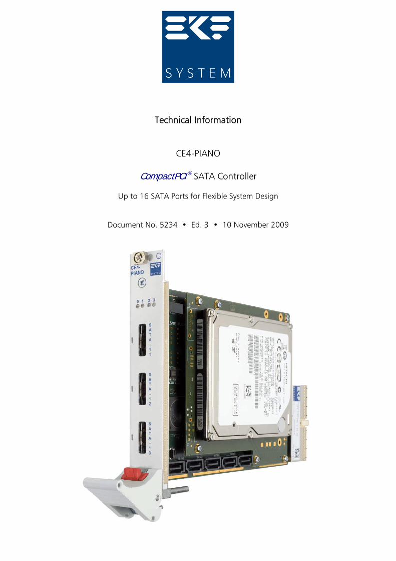
Technical Information
CE4-PIANO
CompactPCI ® SATA Controller
Up to 16 SATA Ports for Flexible System Design
Document No. 5234 • Ed. 3 • 10 November 2009
Technical Information CE4-PIANO • 16-Port CompactPCI® SATA Controller
© EKF -2- ekf.com
Contents
About this Manual . . . . . . . . . . . . . . . . . . . . . . . . . . . . . . . . . . . . . . . . . . . . . . . . . . . . . . . 3Edition History . . . . . . . . . . . . . . . . . . . . . . . . . . . . . . . . . . . . . . . . . . . . . . . . . . . . . 3Related Documents . . . . . . . . . . . . . . . . . . . . . . . . . . . . . . . . . . . . . . . . . . . . . . . . . 4Nomenclature . . . . . . . . . . . . . . . . . . . . . . . . . . . . . . . . . . . . . . . . . . . . . . . . . . . . . 4Trade Marks . . . . . . . . . . . . . . . . . . . . . . . . . . . . . . . . . . . . . . . . . . . . . . . . . . . . . . 4Legal Disclaimer - Liability Exclusion . . . . . . . . . . . . . . . . . . . . . . . . . . . . . . . . . . . . . 4Standards . . . . . . . . . . . . . . . . . . . . . . . . . . . . . . . . . . . . . . . . . . . . . . . . . . . . . . . . 5
CE4-PIANO Features . . . . . . . . . . . . . . . . . . . . . . . . . . . . . . . . . . . . . . . . . . . . . . . . . . . . . . 6Short Description . . . . . . . . . . . . . . . . . . . . . . . . . . . . . . . . . . . . . . . . . . . . . . . . . . . 7Front Panel Variations . . . . . . . . . . . . . . . . . . . . . . . . . . . . . . . . . . . . . . . . . . . . . . 11Block Diagram CE4-PIANO . . . . . . . . . . . . . . . . . . . . . . . . . . . . . . . . . . . . . . . . . . . 13Top/Bottom View Component Assembly . . . . . . . . . . . . . . . . . . . . . . . . . . . . . . . . 15Theory of Operation . . . . . . . . . . . . . . . . . . . . . . . . . . . . . . . . . . . . . . . . . . . . . . . 18Front Panel Connectors . . . . . . . . . . . . . . . . . . . . . . . . . . . . . . . . . . . . . . . . . . . . . 19On-Board Connectors . . . . . . . . . . . . . . . . . . . . . . . . . . . . . . . . . . . . . . . . . . . . . . 19CompactPCI & Rear I/O Connectors . . . . . . . . . . . . . . . . . . . . . . . . . . . . . . . . . . . . 19
Installing and Replacing Components . . . . . . . . . . . . . . . . . . . . . . . . . . . . . . . . . . . . . . . . 20Before You Begin . . . . . . . . . . . . . . . . . . . . . . . . . . . . . . . . . . . . . . . . . . . . . . . . . . 20
Warnings . . . . . . . . . . . . . . . . . . . . . . . . . . . . . . . . . . . . . . . . . . . . . . . . . . 20Caution . . . . . . . . . . . . . . . . . . . . . . . . . . . . . . . . . . . . . . . . . . . . . . . . . . . 20
Installing the Board . . . . . . . . . . . . . . . . . . . . . . . . . . . . . . . . . . . . . . . . . . . . . . . . 21Removing the Board . . . . . . . . . . . . . . . . . . . . . . . . . . . . . . . . . . . . . . . . . . . . . . . 22EMC Recommendations . . . . . . . . . . . . . . . . . . . . . . . . . . . . . . . . . . . . . . . . . . . . . 23
Technical Reference - Connectors . . . . . . . . . . . . . . . . . . . . . . . . . . . . . . . . . . . . . . . . . . . 24Caution . . . . . . . . . . . . . . . . . . . . . . . . . . . . . . . . . . . . . . . . . . . . . . . . . . . . . . . . . 24Please Note . . . . . . . . . . . . . . . . . . . . . . . . . . . . . . . . . . . . . . . . . . . . . . . . . . . . . . 24Front Panel Connectors . . . . . . . . . . . . . . . . . . . . . . . . . . . . . . . . . . . . . . . . . . . . . 25
SATA-11/12/13 eSATA Connectors . . . . . . . . . . . . . . . . . . . . . . . . . . . . . . . 25On-Board Connectors . . . . . . . . . . . . . . . . . . . . . . . . . . . . . . . . . . . . . . . . . . . . . . 26
SATA-01 Docking Header . . . . . . . . . . . . . . . . . . . . . . . . . . . . . . . . . . . . . . 26SATA-14/15/23/24/25 Cable Headers . . . . . . . . . . . . . . . . . . . . . . . . . . . . . 28SATA-21/22 Mezzanine Connector . . . . . . . . . . . . . . . . . . . . . . . . . . . . . . . 28
CompactPCI Connector Suite . . . . . . . . . . . . . . . . . . . . . . . . . . . . . . . . . . . . . . . . . 32J1 CPCI Backplane . . . . . . . . . . . . . . . . . . . . . . . . . . . . . . . . . . . . . . . . . . . . 32J2 SATA Rear I/O . . . . . . . . . . . . . . . . . . . . . . . . . . . . . . . . . . . . . . . . . . . . . 34
Schematics . . . . . . . . . . . . . . . . . . . . . . . . . . . . . . . . . . . . . . . . . . . . . . . . . . . . . . . . . . . . 36

Technical Information CE4-PIANO • 16-Port CompactPCI® SATA Controller
© EKF -3- ekf.com
About this Manual
This manual is a short form description of the technical aspects of the CE4-PIANO, required forinstallation and system integration. It is intended for the advanced user only.
Edition History
EKFDocument
Ed. Contents/Changes Author Date
Text # 5234ce4_tie.wpd
1 Technical Information CE4-PIANOEnglish, Preliminary Edition
jj 21 August 2008
2 Added photos jj 18 September2009
3 Added photos CE4-3 jj 10 November2009
Technical Information CE4-PIANO • 16-Port CompactPCI® SATA Controller
© EKF -4- ekf.com
Related Documents
The CE4-PIANO can be operated in any CompactPCI environment. However, if combined with aCPU board from EKF, some properties of the CE4-PIANO may be configurable in addition viaCPU BIOS setup. For a description of the particular EKF CPU card in use, please refer to thecorrespondent CPU user guide, available by download from www.ekf.com/c/ccpu/ccpu.html.
Nomenclature
Signal names used herein with an attached '#' designate active low lines.
Trade Marks
Some terms used herein are property of their respective owners, e.g.
< ExpressCard™: Trademark PCMCIA< PCI Express®: ® PCI-SIG< Intel, Pentium, Celeron, Pentium M, Core 2 Duo, iAMT: ® Intel< CompactPCI ® : ® PICMG< Windows 2000, Windows XP, Windows Vista: ® Microsoft< EKF, ekf system: ® EKF
EKF does not claim this list to be complete.
Legal Disclaimer - Liability Exclusion
This manual has been edited as carefully as possible. We apologize for any potential mistake.Information provided herein is designated exclusively to the proficient user (system integrator,engineer). EKF can accept no responsibility for any damage caused by the use of this manual.
Technical Information CE4-PIANO • 16-Port CompactPCI® SATA Controller
© EKF -5- ekf.com
Standards
Specifications/Standards
CompactPCI PICMG 2.0 (www.picmg.org)
PCI Local Bus PCI 2.2/2.3/3.0 Standards (PC-SIG www.pcisig.com)
SATAeSATA
http://www.sata-io.orgSerial ATA 2.5 Specification (released October 2005)Serial ATA 2.6 Specification (released February 2007)
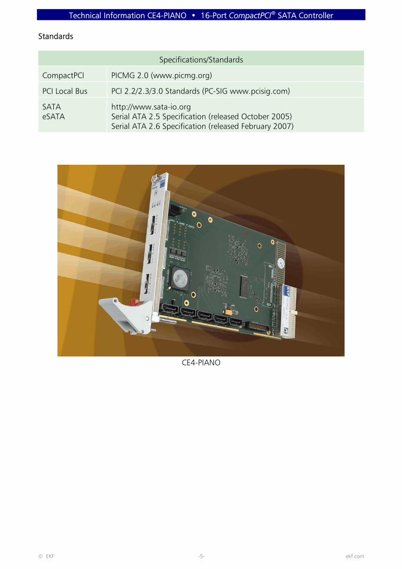
CE4-PIANO
Technical Information CE4-PIANO • 16-Port CompactPCI® SATA Controller
© EKF -6- ekf.com
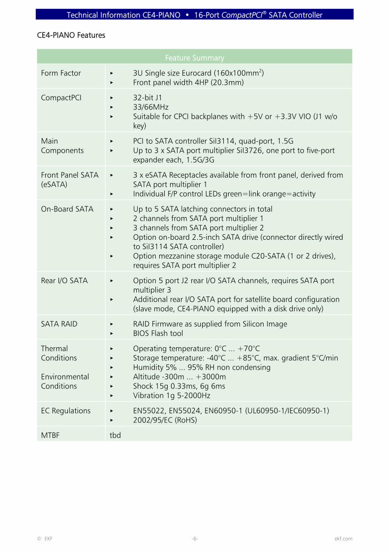
CE4-PIANO Features
Feature Summary
Form Factor < 3U Single size Eurocard (160x100mm2)< Front panel width 4HP (20.3mm)
CompactPCI < 32-bit J1< 33/66MHz< Suitable for CPCI backplanes with +5V or +3.3V VIO (J1 w/o
key)
MainComponents
< PCI to SATA controller SiI3114, quad-port, 1.5G< Up to 3 x SATA port multiplier SiI3726, one port to five-port
expander each, 1.5G/3G
Front Panel SATA(eSATA)
< 3 x eSATA Receptacles available from front panel, derived fromSATA port multiplier 1
< Individual F/P control LEDs green=link orange=activity
On-Board SATA < Up to 5 SATA latching connectors in total< 2 channels from SATA port multiplier 1< 3 channels from SATA port multiplier 2< Option on-board 2.5-inch SATA drive (connector directly wired
to SiI3114 SATA controller)< Option mezzanine storage module C20-SATA (1 or 2 drives),
requires SATA port multiplier 2
Rear I/O SATA < Option 5 port J2 rear I/O SATA channels, requires SATA portmultiplier 3
< Additional rear I/O SATA port for satellite board configuration(slave mode, CE4-PIANO equipped with a disk drive only)
SATA RAID < RAID Firmware as supplied from Silicon Image< BIOS Flash tool
Thermal Conditions
EnvironmentalConditions
< Operating temperature: 0°C ... +70°C< Storage temperature: -40°C ... +85°C, max. gradient 5°C/min< Humidity 5% ... 95% RH non condensing< Altitude -300m ... +3000m< Shock 15g 0.33ms, 6g 6ms< Vibration 1g 5-2000Hz
EC Regulations < EN55022, EN55024, EN60950-1 (UL60950-1/IEC60950-1)< 2002/95/EC (RoHS)
MTBF tbd

Technical Information CE4-PIANO • 16-Port CompactPCI® SATA Controller
© EKF -7- ekf.com
Short Description
Since SATA is todays most popular massstorage interface, the CE4-PIANO has beendeveloped to satisfy the demand for asufficient number of additional SATA ports ina CompactPCI® environment.
The CE4-PIANO is available in differentstuffing options. Bottom-of-the-range, theboard is equipped with a PCI to SATAcontroller chip and an on-board SATA harddisk (or SATA silicon state drive). Thiscombination is a straightforward massstorage solution - plug and play.
For maximum flexibility, the CE4-PIANO canbe optionally populated with up to threeSATA port multipliers in addition, eachoffering five secondary ports. The firstmultiplier is mainly used to control the frontpanel eSATA connectors, the second portmultiplier is engaged in on-board SATA, andthe third multiplier is exclusively dedicated torear I/O SATA.
Option SATA port multiplier 1: Three eSATA connectors are available fromthe front panel for external attachment ofSATA devices. Another two latching SATAconnectors are provided for in-system usagetogether with this option.
Option SATA port multiplier 2: The CE4-PIANO can carry a mezzaninestorage module (C20-SATA) with up to 2SATA hard disk drives, which allows for asimple RAID configuration. Three morelatching SATA connectors come with thisoption.
Option SATA port multiplier 3:Suitable for all situations where rear I/OSATA across J2 is required, either for backpanel connectors and/or system internalSATA connectors, by means of a rear I/Otransition module. Also useful in a scenariowhere one CE4-PIANO acts as a five portSATA master controller, with up to five bareCE4-PIANO cards as satellites (or slaves),equipped with a SATA drive only. A customspecific J2 backplane will be needed inaddition, with the CE4-PIANO master cardworking as SATA hub. The CE4-PIANO slavecards are then addressed via their sidebandSATA channel (slave port on J2, see alsoblock diagram).
Most stuffing options mentioned areconcurrently available. However, consider themaximum SATA data throughput, which issignificantly limited by the CompactPCIbackplane bandwidth, a well knownbottleneck. Hence, the maximum number of16 SATA ports on a CE4-PIANO is merelyprovided for system flexibility.
If your storage application requires highperformance SATA, EKF recommends acompletely different approach, based onmulti-lane PCI Express, realized either asCompactPCI Express card, or as a mezzaninemodule (side board) to any recent EKF CPUboard.
In either case, discuss your individual needswith EKF ([email protected]) in order to find outthe perfect solution for your application.

Technical Information CE4-PIANO • 16-Port CompactPCI® SATA Controller
© EKF -8- ekf.com
CE4-3-PIANO (with SSD)
CE4-3-PIANO (SSD removed)

Technical Information CE4-PIANO • 16-Port CompactPCI® SATA Controller
© EKF -9- ekf.com
CE4-PIANO with C20-SATA Dual Drive Mezzanine
Technical Information CE4-PIANO • 16-Port CompactPCI® SATA Controller
© EKF -10- ekf.com
©EK
Fek
f.co
m
C
E4-P
IAN
O
LED
SATA
-21-
22
SATA-01
SATA-31 toSATA-35
SATA
-25
SATA
-24
SATA
-23
SATA
-15
SATA
-14
C20
-SA
TAM
ezza
nin
eO
pti
on
2.5-
Inch
HD
D/S
SD
SATA-11 SATA-12 SATA-13
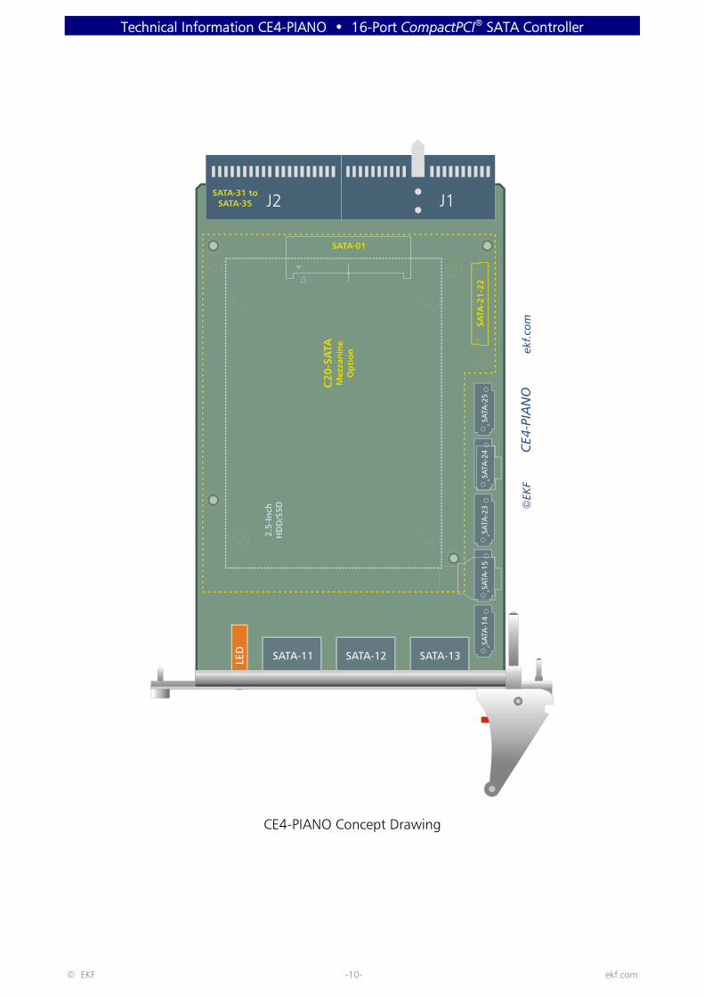
CE4-PIANO Concept Drawing
Technical Information CE4-PIANO • 16-Port CompactPCI® SATA Controller
© EKF -11- ekf.com
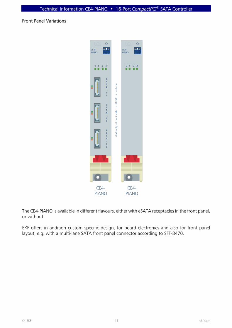
Front Panel Variations
The CE4-PIANO is available in different flavours, either with eSATA receptacles in the front panel,or without.
EKF offers in addition custom specific design, for board electronics and also for front panellayout, e.g. with a multi-lane SATA front panel connector according to SFF-8470.
CE4-PIANO
CE4-PIANO
CE4-PIANO
CE4-PIANO
draf
t on
ly -
do
not
scal
e
EK
F
ek
f.com
•©
•
SATA-13
SATA-12
SATA-11
0 01 12 23 3

Technical Information CE4-PIANO • 16-Port CompactPCI® SATA Controller
© EKF -12- ekf.com
CE4-PIANO Front Panel with eSATA Receptacles
CE4-3-PIANO Closed Front Panel

Technical Information CE4-PIANO • 16-Port CompactPCI® SATA Controller
© EKF -13- ekf.com
Block Diagram CE4-PIANO
CPCI J1RIO J2
CPCI
Back
plan
eCo
nnec
tor
Suite
PCI S
ATA
Cont
rolle
r
Opt
ion
Rear
I/O
SA
TA
Opt
ion
Fron
t Pa
nel S
ATA
SATA
Port
Mul
tiplie
r
SATA
Port
Mul
tiplie
r
Shee
t 1/
2
Sim
plifi
ed B
lock
Dia
gram
CE4-
PIA
NO
Com
pact
PCI S
ATA
Sto
rage
Ada
pter
PCI
32-b
it
Opt
ion
Mez
zani
ne M
odul
eC2
0-SA
TA
22-L
ead
Rece
ptac
le
SATA
SATA
SATA
SATA
SATA
31-3
5
SiI
3114
SiI
3726
SiI
3726
FrontPanelI/O
SATA-11 SATA-12 SATA-13O
ptio
n O
n-Bo
ard
2.5-
Inch
SA
TAH
ard
Dis
k / S
SD
SATA-01
SATA
-14
SATA
-15
© E
KF e
kf.c
om
Shee
t
2
Latc
hed
7-Le
adCo
nnec
tors

Technical Information CE4-PIANO • 16-Port CompactPCI® SATA Controller
© EKF -14- ekf.com
Opt
ion
Mez
zani
ne S
ATA
SATA
Port
Mul
tiplie
r
Hig
h Sp
eed
Mez
zani
neCo
nnec
tor
SATA
SiI
3726
SATA
-21-
22
SATA-23
SATA-25
SATA-24
© E
KF e
kf.c
omSh
eet
1
Latc
hed
7-Le
adCo
nnec
tors
C20
-SA
TASi
ngle
-/D
ual-
HD
D/S
SDM
ezza
nine
Mod
ule
FrontPanelI/O
SATA-11 SATA-12 SATA-13
CPCI J1RIO J2
Shee
t 2/
2
Sim
plifi
ed B
lock
Dia
gram
CE4-
PIA
NO
Com
pact
PCI S
ATA
Sto
rage
Ada
pter
Technical Information CE4-PIANO • 16-Port CompactPCI® SATA Controller
© EKF -15- ekf.com
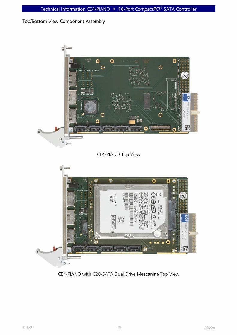
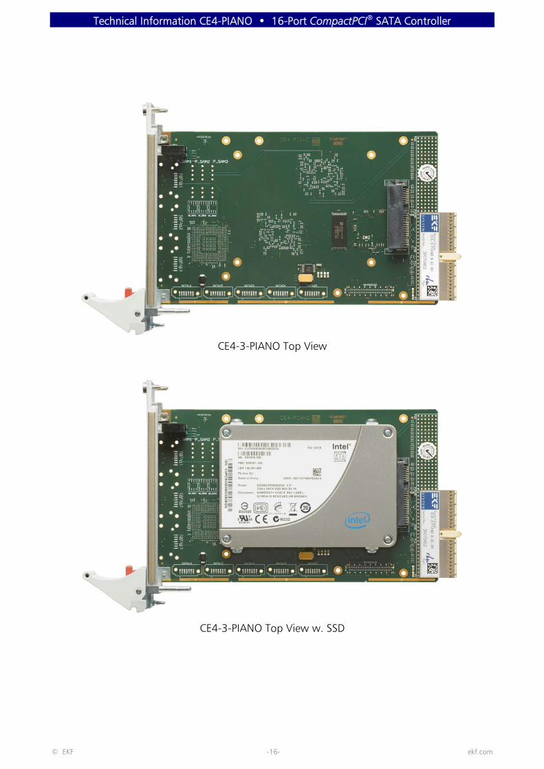
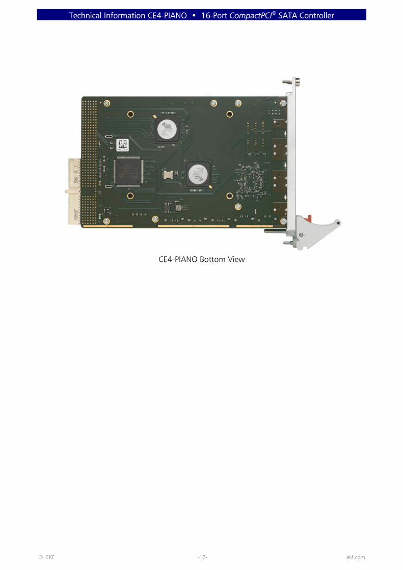
Top/Bottom View Component Assembly
CE4-PIANO Top View
CE4-PIANO with C20-SATA Dual Drive Mezzanine Top View
Technical Information CE4-PIANO • 16-Port CompactPCI® SATA Controller
© EKF -16- ekf.com
CE4-3-PIANO Top View
CE4-3-PIANO Top View w. SSD
Technical Information CE4-PIANO • 16-Port CompactPCI® SATA Controller
© EKF -17- ekf.com
CE4-PIANO Bottom View
Technical Information CE4-PIANO • 16-Port CompactPCI® SATA Controller
© EKF -18- ekf.com
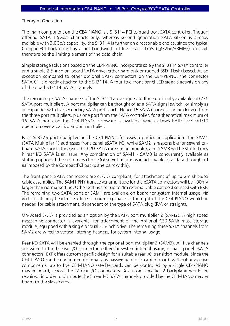
Theory of Operation
The main component on the CE4-PIANO is a SiI3114 PCI to quad-port SATA controller. Thoughoffering SATA 1.5Gb/s channels only, whereas second generation SATA silicon is alreadyavailable with 3.0Gb/s capability, the SiI3114 is further on a reasonable choice, since the typicalCompactPCI backplane has a net bandwidth of less than 1Gb/s (@32bit/33MHz) and willtherefore be the limiting element of the data chain.
Simple storage solutions based on the CE4-PIANO incorporate solely the SiI3114 SATA controllerand a single 2.5-inch on-board SATA drive, either hard disk or rugged SSD (Flash) based. As anexception compared to other optional SATA connectors on the CE4-PIANO, the connectorSATA-01 is directly attached to the SiI3114. A four-fold front panel LED signals activity on anyof the quad SiI3114 SATA channels.
The remaining 3 SATA channels of the SiI3114 are assigned to three optionally available SiI3726SATA port multipliers. A port multiplier can be thought of as a SATA signal switch, or simply asan expander with five secondary SATA ports each. Hence 15 SATA channels can be derived fromthe three port multipliers, plus one port from the SATA controller, for a theoretical maximum of16 SATA ports on the CE4-PIANO. Firmware is available which allows RAID level 0/1/10operation over a particular port multiplier.
Each SiI3726 port multiplier on the CE4-PIANO focusses a particular application. The SAM1(SATA Multiplier 1) addresses front panel eSATA I/O, while SAM2 is responsible for several on-board SATA connectors (e.g. the C20-SATA mezzanine module), and SAM3 will be stuffed onlyif rear I/O SATA is an issue. Any combination of SAM1 - SAM3 is concurrently available asstuffing option at the customers choice (observe limitations in achievable total data throughputas imposed by the CompactPCI backplane bandwidth).
The front panel SATA connectors are eSATA compliant, for attachment of up to 2m shieldedcable assemblies. The SAM1 PHY transceiver amplitude for the eSATA connectors will be 100mVlarger than normal setting. Other settings for up to 4m external cable can be discussed with EKF.The remaining two SATA ports of SAM1 are available on-board for system internal usage, viavertical latching headers. Sufficient mounting space to the right of the CE4-PIANO would beneeded for cable attachment, dependent of the type of SATA plug (R/A or straight).
On-Board SATA is provided as an option by the SATA port multiplier 2 (SAM2). A high speedmezzanine connector is available, for attachment of the optional C20-SATA mass storagemodule, equipped with a single or dual 2.5-inch drive. The remaining three SATA channels fromSAM2 are wired to vertical latching headers, for system internal usage.
Rear I/O SATA will be enabled through the optional port multiplier 3 (SAM3). All five channelsare wired to the J2 Rear I/O connector, either for system internal usage, or back panel eSATAconnectors. EKF offers custom specific design for a suitable rear I/O transition module. Since theCE4-PIANO can be configured optionally as passive hard disk carrier board, without any activecomponents, up to five CE4-PIANO satellite cards can be controlled by a single CE4-PIANOmaster board, across the J2 rear I/O connectors. A custom specific J2 backplane would berequired, in order to distribute the 5 rear I/O SATA channels provided by the CE4-PIANO masterboard to the slave cards.

Technical Information CE4-PIANO • 16-Port CompactPCI® SATA Controller
© EKF -19- ekf.com
Front Panel Connectors
SATA-11SATA-12SATA-13
External SATA (eSATA) connectors, 7-position, for shielded externalSATA cable assemblies up to 2m length, SATA port multiplier 1(SAM1)
On-Board Connectors
SATA-01 SATA Header for a 2.5-inch on-board drive, 7 + 15 position,controlled normally by the on-board SiI3114 SATA controller,configurable (stuffing option) for rear I/O SATA (satellite slaveboard)
SATA-14SATA-15
Vertical latching SATA headers for system internal usage via latchingor non-latching cable assemblies, 7-position, SATA port multiplier 1(SAM1)
SATA-21-22 Hig speed mezzanine connector suitable for attachment of theoptional available C20-SATA storage module, two SATA channels,50-position connector, SATA port multiplier 2 (SAM2)
SATA-23SATA-24SATA-25
Vertical latching SATA headers for system internal usage via latchingor non-latching cable assemblies, 7-position, SATA port multiplier 2(SAM2)
CompactPCI & Rear I/O Connectors
J1 2.00mm unkeyed Hard Metric female connector, according toCompactPCI standards, 32-Bit 33/66MHz
J2 2.00mm Hard Metric female connector, option for rear I/O SATA, 5+ 1 SATA channels, for a proprietary rear I/O transition module, orSATA over a proprietary backplane, in addition GPIO signals, SATAport multiplier 3 (SAM3)
Please note:
Not all of the connectors or other elements listed above may be present or functional on youractual CE4-PIANO board. Assembly of these connectors is highly custom specific. Discuss yourneeds (target application) with EKF before ordering, for an optimum board configuration.

Technical Information CE4-PIANO • 16-Port CompactPCI® SATA Controller
© EKF -20- ekf.com
Installing and Replacing Components
Before You Begin
Warnings
The procedures in this chapter assume familiarity with the general terminology associated withindustrial electronics and with safety practices and regulatory compliance required for using andmodifying electronic equipment. Disconnect the system from its powersource and from any telecommunication l inks, networks or modems beforeperforming any of the procedures described in this chapter. Failure todisconnect power, or telecommunication links before you open the system orperform any procedures can result in personal injury or equipment damage.Some parts of the system can continue to operate even though the power switch is in its offstate.
Caution
Electrostatic discharge (ESD) can damage components. Perform the procedures described in thischapter only at an ESD workstation. If such a station is not available, you canprovide some ESD protection by wearing an antistatic wrist strap and attaching itto a metal part of the system chassis or board front panel. Store the board onlyin its original ESD protected packaging. Retain the original packaging (antistaticbag and antistatic box) in case of returning the board to EKF for repair.

Technical Information CE4-PIANO • 16-Port CompactPCI® SATA Controller
© EKF -21- ekf.com
Installing the Board
Warning
This procedure should be done only by qualified technical personnel. Disconnect the systemfrom its power source before doing the procedures described here. Failure to disconnect power,or telecommunication links before you open the system or perform any procedures can result inpersonal injury or equipment damage.
Typically you will perform the following steps:
C Switch off the system, remove the AC power cord
C Attach your antistatic wrist strap to a metallic part of the system
C Remove the board packaging, be sure to touch the board only at the front panel
C Identify the related CompactPCI slot (peripheral slot for I/O boards, system slot for CPUboards, with the system slot typically most right or most left to the backplane)
C Insert card carefully (be sure not to damage components mounted on the bottom side ofthe board by scratching neighboured front panels)
C A card with on-board connectors requires attachment of associated cabling now
C Lock the ejector lever, fix screws at the front panel (top/bottom)
C Retain original packaging in case of return

Technical Information CE4-PIANO • 16-Port CompactPCI® SATA Controller
© EKF -22- ekf.com
Removing the Board
Warning
This procedure should be done only by qualified technical personnel. Disconnect the systemfrom its power source before doing the procedures described here. Failure to disconnect power,or telecommunication links before you open the system or perform any procedures can result inpersonal injury or equipment damage.
Typically you will perform the following steps:
C Switch off the system, remove the AC power cord
C Attach your antistatic wrist strap to a metallic part of the system
C Identify the board, be sure to touch the board only at the front panel
C Unfasten both front panel screws (top/bottom), unlock the ejector lever
C Remove any on-board cabling assembly
C Activate the ejector lever
C Remove the card carefully (be sure not to damage components mounted on the bottomside of the board by scratching neighboured front panels)
C Store board in the original packaging, do not touch any components, hold the board atthe front panel only
Warning
Do not expose the card to fire. Battery cells and other components couldexplode and cause personal injury.

Technical Information CE4-PIANO • 16-Port CompactPCI® SATA Controller
© EKF -23- ekf.com
EMC Recommendations
In order to comply with the CE regulations for EMC, it is mandatory to observe the followingrules:
C The chassis or rack including other boards in use must comply entirely with CE
C Close all board slots not in use with a blind front panel
C Front panels must be fastened to the enclosure by built-in screws
C Cover any unused front panel mounted connector with a shielding cap
C External communications cable assemblies must be shielded (shield connected only atone end of the cable)
C Use ferrite beads for cabling wherever appropriate
C Some connectors may require additional isolating parts
Reccomended Accessories
Blind CPCI FrontPanels
EKF Elektronik Widths currently available(1HP=5.08mm):with handle 4HP/8HPwithout handle2HP/4HP/8HP/10HP/12HP
Ferrit Bead Filters ARP Datacom,63115 Dietzenbach
Ordering No.102 820 (cable diameter 6.5mm)102 821 (cable diameter 10.0mm)102 822 (cable diameter 13.0mm)
Metal ShieldingCaps
Conec-Polytronic,59557 Lippstadt
Ordering No.CDFA 09 165 X 13129 X (DB9)CDSFA 15 165 X 12979 X (DB15)CDSFA 25 165 X 12989 X (DB25)

Technical Information CE4-PIANO • 16-Port CompactPCI® SATA Controller
© EKF -24- ekf.com
Technical Reference - Connectors
Caution
Some of the connectors may provide operating voltage (e.g. +12V, +5V and +3.3V) to devicesinside the system chassis, such as internal peripherals. Not all of these connectors areovercurrent protected. Do not use these connectors for powering devices external to thecomputer chassis. A fault in the load presented by the external devices could cause damage tothe board, the interconnecting cable and the external devices themselves.
Please Note
The CE4-PIANO mezzanine module may be equipped with several front panel - , on-board - andrear I/O connectors for system internal and/or external usage. Not all of these connectors may bepresent on a particular board. Be sure to specify your individual needs when ordering the CE4-PIANO board. Characteristic features and the pin assignments of each connector are describedon the following pages (connector designation in alphabetical order within the groups 'frontpanel connectors', 'on-board connectors', and 'rear I/O connectors').

Technical Information CE4-PIANO • 16-Port CompactPCI® SATA Controller
© EKF -25- ekf.com
Front Panel Connectors
SATA-11/12/13 eSATA Connectors
The CE4-PIANO can be optionally equipped with 3 front panel eSATA signal headers. TX/RXdesignation of signals are shown with respect to the SATA port multiplier 1 (SAM1). Shieldedexternal SATA cable assemblies are recommended for reliable industrial usage. A dual LED isassociated to each eSATA receptacle - green signals an established link between the CE4-PIANOand the attached device, and orange will indicate activity on a particular port.
3 x F/P eSATA #256.007.10.10 Receptacles
1 GND
2 SATA_TX+
3 SATA_TX-
4 GND
5 SATA_RX-
6 SATA_RX+
7 GND
The typical external cable length should not exceed 2m. For special applications the SAM1 SATAPHYs can be individually adjusted to compensate for signal distortions over up to 4m cablelength (stuffing option, has to be specified when ordering).
Remember that SATA is a high speed data link. Chose the minimum distance possible forlocating the external SATA device, and use high quality cable assemblies for reliable industrialoperation, such as the Molex 68782 series (EKF part no. 256.007.82.10 and 256.007.82.20).Compared to internal SATA cabling, the CE4-PIANO eSATA front panel connectors offer superiorshielding and provide EMI protection. eSATA connectors and cable harnesses used or suppliedby EKF adhere to the design specifications recommended by the Serial ATA InternationalOrganization (SATA-IO).
For experimental purposes, there are also adapter cable assemblies available from eSATA toSATA (EKF part no. 256.007.81.10).
The SATA-11/12/13 front panel connectors are assigned to the SATA port multiplier 1 (SAM1).Another two SATA channels for system internal usage are associated to SAM1 - refer to theSATA-14 and SATA-15 description.
eSA
TA R
ecep
tacl
e25
6.00
7.10
.10
• ©
EKF
• e
kf.c
om

Technical Information CE4-PIANO • 16-Port CompactPCI® SATA Controller
© EKF -26- ekf.com
On-Board Connectors
The CE4-PIANO can be equipped with several on-board connectors. These connectors areavailable as an option only, or even exclusive to each other, and therefore may not be functionalor even present on your actual board.
Assembly of these connectors is highly custom specific. Discuss your needs with EKF beforeordering, so that the optimum board configuration for your application will be chosen.
SATA-01 Docking Header
As an option, the CE4-PIANO can be equipped with an on-board 2.5-inch SATA drive, eitherhard disk (HDD), or silicon state (SSD). The 22-position SATA docking header SATA-01 allows fordirect attachment of any drive, without a cable assembly.
Signal designations RX/TX with respect to the SATA host controller. Data signals can be derivedeither from the on-board controller chip SiI3114, which situation is referred to as 'master'configuration, or optionally from the rear I/O connector J2, which is referred to as 'slave'configuration.
SATA-01 • SATA Docking Connector 15+7 • 256.022.10.01
S1 GND
S2 TX+ SATA01
S3 TX- SATA01
S4 GND
S5 RX- SATA01
S6 RX+ SATA01
S7 GND
P1 +3.3V
P2 +3.3V
P3 +3.3V
P4 GND
P5 GND
P6 GND
P7 +5V
P8 +5V
P9 +5V
P10 GND
P11 RSVD
P12 GND
P13 +12V
P14 +12V
P15 +12V
Part
No.
256
.022
.10.
01 •
SATA
Hos
t Re
cept
acle
• ©
EKF
• e
kf.c
om
Technical Information CE4-PIANO • 16-Port CompactPCI® SATA Controller
© EKF -27- ekf.com
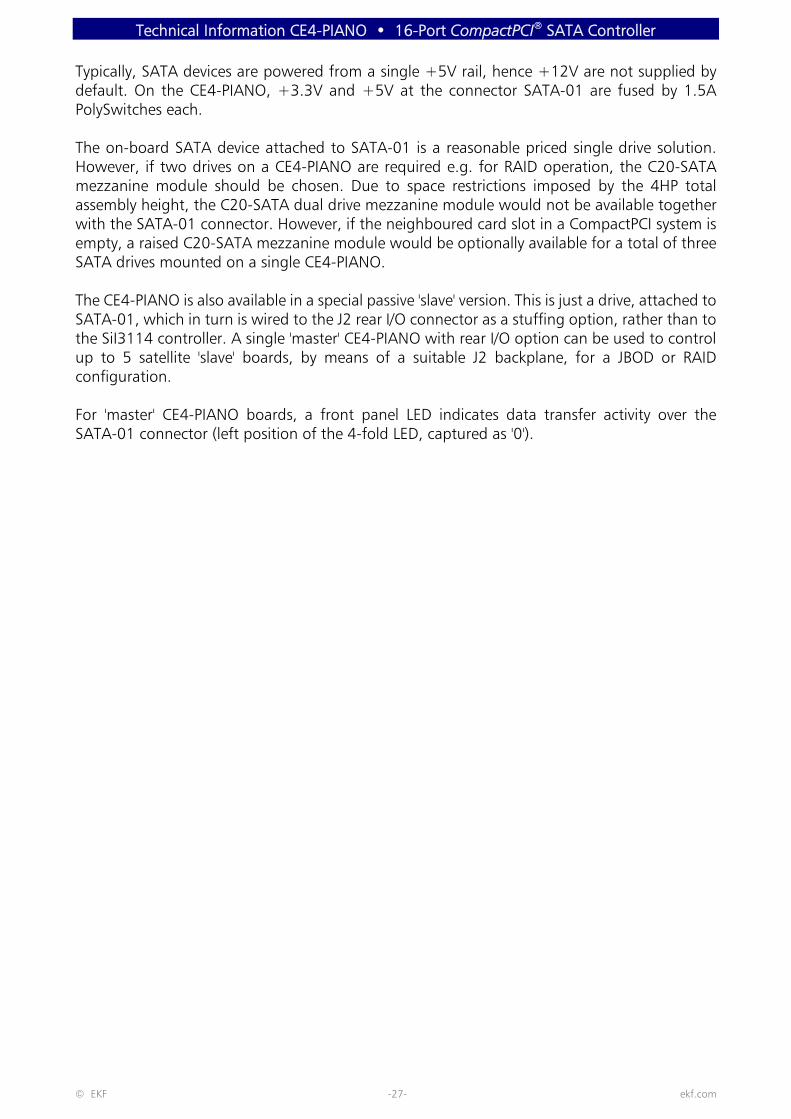
Typically, SATA devices are powered from a single +5V rail, hence +12V are not supplied bydefault. On the CE4-PIANO, +3.3V and +5V at the connector SATA-01 are fused by 1.5APolySwitches each.
The on-board SATA device attached to SATA-01 is a reasonable priced single drive solution.However, if two drives on a CE4-PIANO are required e.g. for RAID operation, the C20-SATAmezzanine module should be chosen. Due to space restrictions imposed by the 4HP totalassembly height, the C20-SATA dual drive mezzanine module would not be available togetherwith the SATA-01 connector. However, if the neighboured card slot in a CompactPCI system isempty, a raised C20-SATA mezzanine module would be optionally available for a total of threeSATA drives mounted on a single CE4-PIANO.
The CE4-PIANO is also available in a special passive 'slave' version. This is just a drive, attached toSATA-01, which in turn is wired to the J2 rear I/O connector as a stuffing option, rather than tothe SiI3114 controller. A single 'master' CE4-PIANO with rear I/O option can be used to controlup to 5 satellite 'slave' boards, by means of a suitable J2 backplane, for a JBOD or RAIDconfiguration.
For 'master' CE4-PIANO boards, a front panel LED indicates data transfer activity over theSATA-01 connector (left position of the 4-fold LED, captured as '0').
Technical Information CE4-PIANO • 16-Port CompactPCI® SATA Controller
© EKF -28- ekf.com
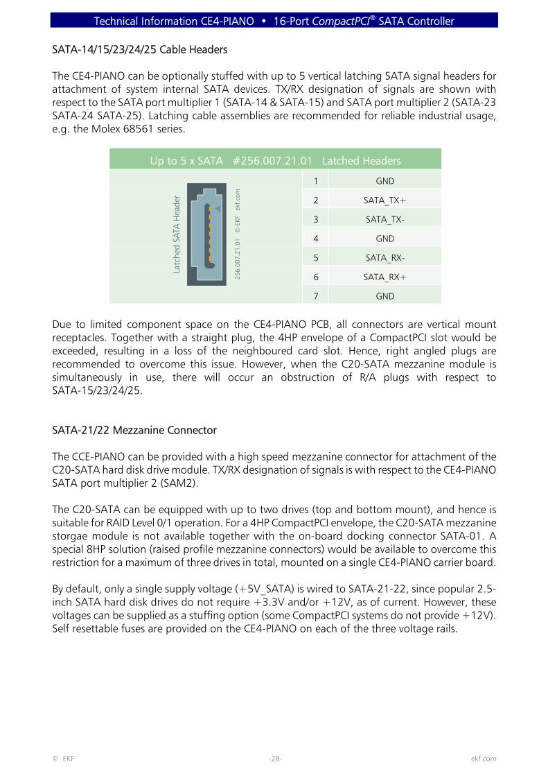
SATA-14/15/23/24/25 Cable Headers
The CE4-PIANO can be optionally stuffed with up to 5 vertical latching SATA signal headers forattachment of system internal SATA devices. TX/RX designation of signals are shown withrespect to the SATA port multiplier 1 (SATA-14 & SATA-15) and SATA port multiplier 2 (SATA-23SATA-24 SATA-25). Latching cable assemblies are recommended for reliable industrial usage,e.g. the Molex 68561 series.
Up to 5 x SATA #256.007.21.01 Latched Headers
1 GND
2 SATA_TX+
3 SATA_TX-
4 GND
5 SATA_RX-
6 SATA_RX+
7 GND
Due to limited component space on the CE4-PIANO PCB, all connectors are vertical mountreceptacles. Together with a straight plug, the 4HP envelope of a CompactPCI slot would beexceeded, resulting in a loss of the neighboured card slot. Hence, right angled plugs arerecommended to overcome this issue. However, when the C20-SATA mezzanine module issimultaneously in use, there will occur an obstruction of R/A plugs with respect toSATA-15/23/24/25.
SATA-21/22 Mezzanine Connector
The CCE-PIANO can be provided with a high speed mezzanine connector for attachment of theC20-SATA hard disk drive module. TX/RX designation of signals is with respect to the CE4-PIANOSATA port multiplier 2 (SAM2).
The C20-SATA can be equipped with up to two drives (top and bottom mount), and hence issuitable for RAID Level 0/1 operation. For a 4HP CompactPCI envelope, the C20-SATA mezzaninestorgae module is not available together with the on-board docking connector SATA-01. Aspecial 8HP solution (raised profile mezzanine connectors) would be available to overcome thisrestriction for a maximum of three drives in total, mounted on a single CE4-PIANO carrier board.
By default, only a single supply voltage (+5V_SATA) is wired to SATA-21-22, since popular 2.5-inch SATA hard disk drives do not require +3.3V and/or +12V, as of current. However, thesevoltages can be supplied as a stuffing option (some CompactPCI systems do not provide +12V).Self resettable fuses are provided on the CE4-PIANO on each of the three voltage rails.
Latc
hed
SATA
Hea
der
256.
007.
21.0
1 ©
EKF
ek
f.com

Technical Information CE4-PIANO • 16-Port CompactPCI® SATA Controller
© EKF -29- ekf.com
SATA-21-22 SATA Expansion Interface1.00mm Pitch Male Connector 2mm Height (275.90.02.068.51)
GND b1 a1 GND
b2 a2 SATA0_TXP
b3 a3 SATA0_TXN
GND b4 a4 GND
b5 a5 SATA0_RXN
b6 a6 SATA0_RXP
GND b7 a7 GND
b8 a8 SATA1_TXP
b9 a9 SATA1_TXN
GND b10 a10 GND
b11 a11 SATA1_RXN
b12 a12 SATA1_RXP
GND b13 a13 GND
b14 a14
b15 a15
GND b16 a16 GND
b17 a17
b18 a18
b19 a19
b20 a20
b21 a21
+5V_SATA b22 a22 +3.3V_SATA
+5V_SATA b23 a23 +3.3V_SATA
b24 a24
b25 a25 +12V_SATA
Notes:
< +3.3V_SATA is not connected by default - stuffing option together with 1.5A PolySwitchresettable fuse
< +5V_SATA across 1.5A PolySwitch resettable fuse< +12V_SATA is not connected by default - stuffing option together with 0.5A PolySwitch
resettable fuse< All sx pins (shield) are tied to GND< All TX/RX designations with respect to SiI3726 SATA port multiplier 2 (TX controller = RX
drive, RX controller = TX drive)
a1
s1
s9s18
s10
a25b25
b1
1.00
mm
Pitc
h H
igh
Spee
d M
ale
Conn
ecto
r
© E
KF
275.
90.0
2.06
8.51
ek
f.com

Technical Information CE4-PIANO • 16-Port CompactPCI® SATA Controller
© EKF -30- ekf.com
C20-SATA Mezzanine Module
C20-SATA Storage Module (Single or Dual Drive)
Technical Information CE4-PIANO • 16-Port CompactPCI® SATA Controller
© EKF -31- ekf.com
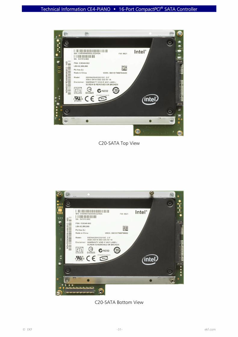
C20-SATA Top View
C20-SATA Bottom View
Technical Information CE4-PIANO • 16-Port CompactPCI® SATA Controller
© EKF -32- ekf.com
CompactPCI Connector Suite
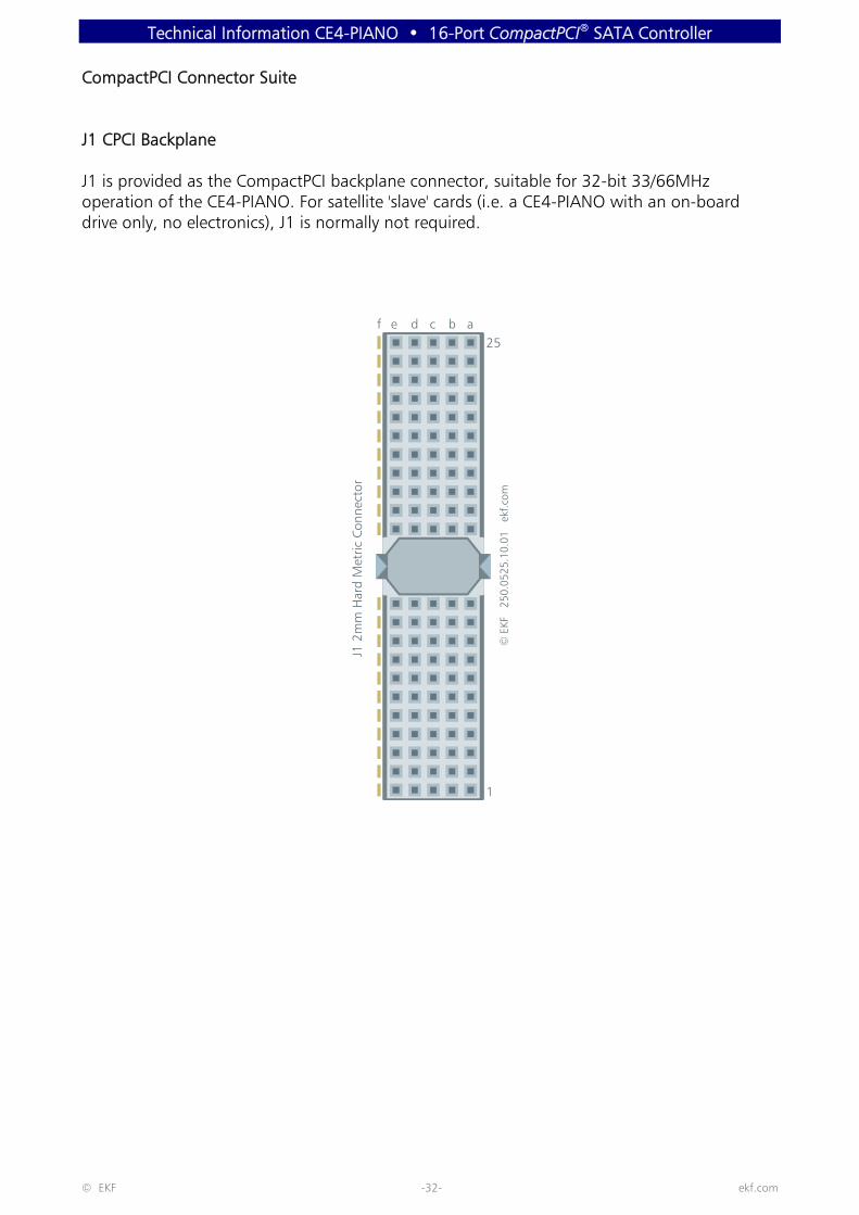
J1 CPCI Backplane
J1 is provided as the CompactPCI backplane connector, suitable for 32-bit 33/66MHzoperation of the CE4-PIANO. For satellite 'slave' cards (i.e. a CE4-PIANO with an on-boarddrive only, no electronics), J1 is normally not required.
1
25J1
2m
m H
ard
Met
ric C
onne
ctor
© E
KF
250.
0525
.10.
01
ekf.c
om
abcdef

Technical Information CE4-PIANO • 16-Port CompactPCI® SATA Controller
© EKF -33- ekf.com
#J1 A B C D E
25 +5V REQ64# ENUM# +3.3V +5V
24 AD1 +5V VI/O AD0 ACK64#
23 +3.3V AD4 AD3 +5V AD2
22 AD7 GND +3.3V AD6 AD5
21 +3.3V AD9 AD8 M66EN C/BE0#
20 AD12 GND VI/O AD11 AD10
19 +3.3V AD15 AD14 GND AD13
18 SERR# GND +3.3V PAR C/BE1#
17 +3.3V IPMB SCL IPMB SDA GND PERR#
16 DEVSEL# GND VI/O STOP# LOCK#
15 +3.3V FRAME# IRDY# BD_SEL# TRDY#
14
13 Not Keyed
12
11 AD18 AD17 AD16 GND C/BE2#
10 AD21 GND +3.3V AD20 AD19
9 C/BE3# IDSEL AD23 GND AD22
8 AD26 GND VI/O AD25 AD24
7 AD30 AD29 AD28 GND AD27
6 REQ# GND +3.3V CLK AD31
5 BRSVP1A5 BRSVP1B5 RST# GND GNT#
4 IPMB PWR HEALTHY# VI/O INTP INTS
3 INTA# INTB# INTC# +5V INTD#
2 TCK +5V TMS TDO 1 TDI 1
1 +5V -12V 2 TRST# +12V 3 +5V
1 TDO - TDI internally connected
2 -12V not in use
3 +12V typically not used

Technical Information CE4-PIANO • 16-Port CompactPCI® SATA Controller
© EKF -34- ekf.com
J2 SATA Rear I/O
As an option, the CE4-PIANO can be configured for rear I/O SATA across the connector J2. Allfive SATA channels from the SATA port multiplier 3 (SAM3) are routed to J2, either for usagetogether with a custom specific rear I/O transition module, or a custom specific SATAbackplane. As a matter of course, the rear I/O option is not suitable together with a 64-bitCompactPCI backplane, due to signal interference.
A rear I/O transition module could be designed for system internal and/or back panel externalusage of the SATA channels.
A proprietary SATA backplane would distribute the SATA channels from a 'master' CE4-PIANOslot (acting as a controller hub) to a maximum of 5 'slave' card slots, equipped with just adrive each.
Also a combined SATA backplane and transition module solution can be designed.
In addition to the SATA channels, the connector J2 provides a lot of GPIO signals, derivedfrom SAM3 (3.3V compliant).
© E
KF
250.
0522
.10.
01
ekf.c
om
1
22
J2 2
mm
Met
ric C
onne
ctor
abcdef
Technical Information CE4-PIANO • 16-Port CompactPCI® SATA Controller
© EKF -35- ekf.com
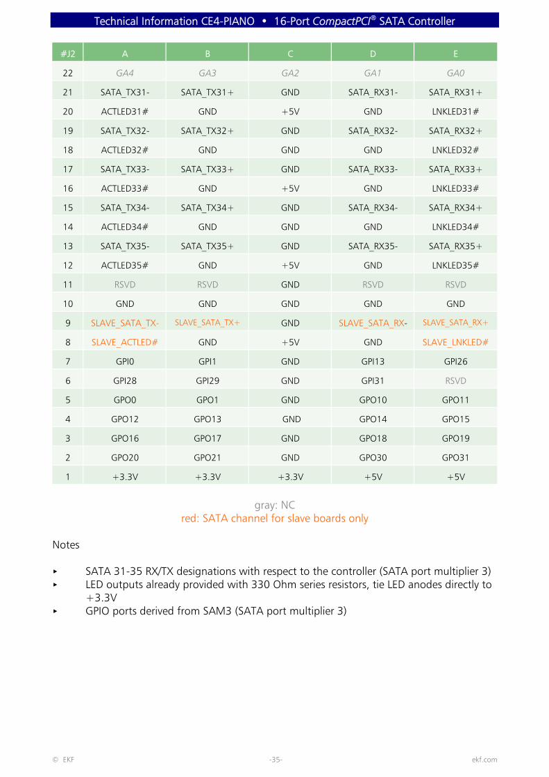
#J2 A B C D E
22 GA4 GA3 GA2 GA1 GA0
21 SATA_TX31- SATA_TX31+ GND SATA_RX31- SATA_RX31+
20 ACTLED31# GND +5V GND LNKLED31#
19 SATA_TX32- SATA_TX32+ GND SATA_RX32- SATA_RX32+
18 ACTLED32# GND GND GND LNKLED32#
17 SATA_TX33- SATA_TX33+ GND SATA_RX33- SATA_RX33+
16 ACTLED33# GND +5V GND LNKLED33#
15 SATA_TX34- SATA_TX34+ GND SATA_RX34- SATA_RX34+
14 ACTLED34# GND GND GND LNKLED34#
13 SATA_TX35- SATA_TX35+ GND SATA_RX35- SATA_RX35+
12 ACTLED35# GND +5V GND LNKLED35#
11 RSVD RSVD GND RSVD RSVD
10 GND GND GND GND GND
9 SLAVE_SATA_TX- SLAVE_SATA_TX+ GND SLAVE_SATA_RX- SLAVE_SATA_RX+
8 SLAVE_ACTLED# GND +5V GND SLAVE_LNKLED#
7 GPI0 GPI1 GND GPI13 GPI26
6 GPI28 GPI29 GND GPI31 RSVD
5 GPO0 GPO1 GND GPO10 GPO11
4 GPO12 GPO13 GND GPO14 GPO15
3 GPO16 GPO17 GND GPO18 GPO19
2 GPO20 GPO21 GND GPO30 GPO31
1 +3.3V +3.3V +3.3V +5V +5V
gray: NCred: SATA channel for slave boards only
Notes
< SATA 31-35 RX/TX designations with respect to the controller (SATA port multiplier 3)< LED outputs already provided with 330 Ohm series resistors, tie LED anodes directly to
+3.3V< GPIO ports derived from SAM3 (SATA port multiplier 3)

Technical Information CE4-PIANO • 16-Port CompactPCI® SATA Controller
Schematics
Complete circuit diagrams for this product are available for customers on request. Signing ofa non-disclosure agreement would be needed. Please contact [email protected] for details.
EKF reserves the right to refuse distribution of confidential information material for any reasonthat EKF may consider substantial.
Industrial Computers Made in Germanyboards. systems. solutions.
EKF Elektronik GmbHPhilipp-Reis-Str. 459065 HAMMGermany
Phone +49 (0)2381/6890-0Fax +49 (0)2381/6890-90
Internet www.ekf.comE-Mail [email protected]