technical guide for perle’s cisco ios style command … · technical guide for perle’s cisco...
TRANSCRIPT

Technical Guide for Perle’s Cisco IOSTM Style Command Line Interface
5500119-10

Technical Guide for Perle’s Cisco IOSTM Style Command Interface

Technical Guide for Perle’s Cisco IOSTM Style Command Line Interface
Technical Guide for Perle’s Cisco IOSTM Style
Command Line Interface
In this manual you will read about:
! Introduction to Cisco Configuration Mode! Overview of 833IS! Differences between 833IS and Cisco Products! Command Overview! Installation and Configuration of 833IS in Cisco Configuration Mode! Monitoring the 833IS! Differences between 833IS Manager and Cisco Management! Index of Supported Commands
! Login Username#
! User EXEC hostname>
! Privileged EXEChostname#
! Configuration hostname(config)#
! Interface (Ethernet, Token Ring, ISDN)hostname(config-if)#
! IP Filter Configurationhostname(config-ip-ext-na)#
! IPX Filter Configuration hostname(config-ipx-ext-na)#
! Line Interface hostname(config-line)#
! Group Configuration hostname(config-group)#
! Standard Profile Configuration hostname(config-stdUser)#
! userdb Configuration hostname(config-user)#
! Key Chain Configuration hostname(config-key-chain)#
! Router Configuration hostname(config-rr)#
Technical Guide for Perle’s Cisco IOSTM Style Command Interface 1

Introduction to Cisco Configuration Mode
! Override Standard Profile Configuration hostname(config-user-override)#
! Supported Command Set Definitions! EXEC Mode
! Global Configuration
! Group Configuration
! Interface (Ethernet, Token Ring and ISDN)
! IP Access-List Extended Configuration
! IPX Access-List Extended Configuration
! Key Chain Configuration
! Key Configuration
! Line Interface Configuration
! Override Standard-Profile Configuration
! Router Configuration
! Standard-Profile Configuration
! userdb Configuration
Introduction to Cisco Configuration ModeThe Cisco Configuration Mode is designed to allow personnel, trained in installation and configuration of CiscoTM products, to manage and configure the 833IS using the same techniques applied to similar Cisco units. Information within this manual is aimed towards people who are thoroughly trained in installations of Cisco products. For others, it is strongly recommended that you follow the standard installation and configuration procedures to manage the 833IS unit.
The Cisco Configuration Mode was designed to present a familiar model and concepts similar to Cisco products. The same procedures and commands that are used to manage the installation and configuration of a Cisco device can be used to configure and manage the 833IS. For example, access to the program storage on flash on a Cisco router is handled like a disk drive. The firmware and configuration storage on the flash on the 833IS can also be accessed like a disk drive through various Cisco commands.
Although the Cisco Configuration Mode for the 833IS is similar to managing Cisco products, there are several unique features of the 833IS that the user should be mindful of. Initial configuration of the 833IS is performed on the front panel instead of a direct serial connection to establish LAN connections. Also, the 833IS unit powers up in a factory default mode from the bootFlash volume. This volume is read-only and protects the unit from any modifications to the factory default
2 Technical Guide for Perle’s Cisco IOSTM Style Command Interface

Technical Guide for Perle’s Cisco IOSTM Style Command Line Interface
firmware files in flash memory.
Similar procedures and commands for managing the installation and configuration of Cisco products are incorporated into Cisco Configuration Mode. Familiar key sequences and Cisco commands, wherever possible, are used to manage and configure the 833IS through a Command Line Interface accessed via Telnet. Perle commands, similar in format to Cisco commands, can be used whenever Cisco commands are not applicable for configuring the 833IS unit.
In Cisco Configuration Mode, simple raw commands are required to configure the 833IS unit. However, there is no equivalent Cisco “Setup” script to initially configure the unit. Therefore, it is recommended that the 833IS Manager, a Windows-based application, be used to create an initial configuration for the 833IS. This Manager software has intelligent defaults that will meet the needs of most installations. The configuration can then be customized and updated using Cisco Configuration Mode.
Regardless of the method with which you configure the 833IS unit, you can view the statistics and current status of the 833IS via Telnet. Using standard Cisco commands and/or a Syslog server, events occurring on the 833IS can be monitored and analyzed.
Overview of 833ISThe 833IS allows Remote Users access to the LAN via telephone lines. The RemoteUsers can then access network file servers, printers, e-mail or any other servers onthe LAN. It can even act as a Dial-In gateway to another network, such as theInternet.
The 833IS unit is designed with the following features:! 10/100 Mbps Ethernet or 4/16 Mbps Token Ring LAN connection
! up to 8 ISDN, BRI lines with either ‘U’ or ‘S/T’ interface, each supporting up to 2simultaneous phone calls (analog or digital) allowing for a total of 16 simultaneouscalls.
! designed with 4 MB flash memory with a 512K bootFlash volume (ROM) and flash(Read/Write) volume.
! NVRAM on the unit has a 64K nvram volume which the “startup-config” is stored.
Technical Guide for Perle’s Cisco IOSTM Style Command Interface 3

Overview of 833IS
Similar to Cisco products the dial topology for the 833IS is illustrated by the following diagram.
Initially, the 833IS unit powers up using the bootFlash volume which contains the factory default firmware for the unit. The factory default firmware is the limited code required for the unit to function. This factory default firmware would be equivalent to Cisco’s bootstrap system software.
The flash volume is a Read/Write flash memory where versions of firmware or configuration files for the 833IS can be stored.
The 833IS can be updated by downloading a new release firmware image to the flash volume using the 833IS Manager or TFTP. The release firmware filename convention that is used for the 833IS are as follows:
pcc6600s.img :BRI Line with ‘S/T’ interfacepcc6600u.img :BRI Line with ‘U’interface
4 Technical Guide for Perle’s Cisco IOSTM Style Command Interface

Technical Guide for Perle’s Cisco IOSTM Style Command Line Interface
The startup configuration is a text file stored on the nvram volume on the 833IS. Similar to Cisco products, the “startup-config” is applied upon bootup of the unit. Downloading configuration files using the 833IS Manager will update the “startup-config” file but requires the user to reboot the unit for the configuration changes to be applied. However, through a Telnet session, any dynamic changes to the configuration are stored in the run-time configuration or “running-config” and most modifications take effect immediately. In order to save these new configuration parameters for bootup, the file must be saved to the “startup-config” file.
The 833IS can hold up to two Feature cards. The card in Slot 1 is called the System card and the card in Slot 2 is called the Expansion card. The system card is the main processing card and must be present in the 833IS in Slot 1, but the Expansion card is optional.
The 833IS has a maximum of 8 BRI lines with 4 BRI lines on the System card and optionally another 4 BRI lines on the Expansion card. Each of these interfaces are mapped to a specific number. The interface mapping is 0 based, from 0 to 7, with 0 being the first interface on the System card and 4 being the first interface on the Expansion Card in Slot 2.
The Interface dialer condenses the configuration process and applies common configuration parameters to all BRI interfaces. The 833IS’s group-asynchronous interface also applies generic configuration parameters as a single entity to all asynchronous interfaces. This method is used instead of individual configuration for each asynchronous interface on the 833IS.
Individual users can be configured and authenticated upon each dial-in connection. The user configuration can organize users based upon department and allow individual users specific privileges. User features like expiration date and inactivity timers can also be specified for each user.
Differences Between 833IS and Cisco ProductsAlthough the design concepts and dial-in topology between the 833IS and Cisco router products are similar there are specific differences that the users should be aware of.
As explained in the Overview section, the 833IS is powered up and initially has a default Factory firmware and configuration. Although various firmware versions can be stored in flash memory, the default Factory firmware is stored in the bootFlash (read-only) volume which users cannot modify. This protects the 833IS unit from any corruption to the factory firmware. For instance, if a user deletes all
Technical Guide for Perle’s Cisco IOSTM Style Command Interface 5

Differences Between 833IS and Cisco Products
firmware versions from flash volume, the 833IS will then still run in factory mode upon bootup.
Instead of initial configuration being performed over a direct serial connection, the 833IS configures IP parameters through the front panel of the unit. The 833IS is able to configure the IP Address, gateway, subnet mask and LAN speed from the front panel enabling connections to be established across the LAN (Ethernet or Token Ring). The 833IS can then be accessed by a console through a Telnet session.
Although Cisco products allow access to internal resources such as queues and buffer sizes, Perle has protected these internal resources and restricts users from modifying them to maintain the integrity and quality of the product.
The interface mapping on the 833IS differs from that on the Cisco router. The card’s BRI interfaces are 0 based from 0 to 7 (e.g. the first 4 BRI interfaces are located on card 1 mapped 0-3, the second 4 BRI interfaces are on card 2 mapped 4-7). On the 833IS, some commands that are applied to a specific interface will be applied all interfaces that reside on the card. When interactively executing some commands (i.e. isdn switch type, isdn _minitel) to a specific interface, notification messages are displayed indicating which interfaces have been modified. For example, the following command at the global configuration level will set all interfaces in the router to Northern Telecom DMS-100 switch type:
isdn switch type basic-dms100
The following commands will set the BRI interfaces 4-7 to DMS-100 and sets interfaces 0-3 to 5ESS since the interface bri 0 command applies to all interfaces residing on the same card.
isdn switch type basic-dms100
interface bri 0
isdn switch type basic-5ess
A notification message will be displayed indicating what interfaces have been modified:
“Parameter change applies to all interfaces numbered from 0-3.”
The 833IS handles WAN interfaces differently than Cisco products. Cisco configures IP parameters for each individual WAN interface on the unit. Each WAN interfaces on a Cisco product is considered an individual entity connected to a router which then routes to a device on a LAN.
6 Technical Guide for Perle’s Cisco IOSTM Style Command Interface

Technical Guide for Perle’s Cisco IOSTM Style Command Line Interface
For IP, the 833IS looks like a router between two networks. The first network iscomprised of the devices on the LAN. The second network, referred to as the"Internal WAN network", is comprised of all IP clients and routers that are dialedinto the WAN ports.
Setting up a basic 833IS IP configuration requires the following:
! Defining the network on the LAN side, and defining the address of the LANrouter port.
! Defining the network on the WAN side, and defining the address of the WANrouter port.
All clients dialed into the WAN, see the same address for this WAN router port.
! Each client dialing in requires a unique IP address. The 833IS supports multiplemethods for defining and supplying IP addresses to clients.
If a router dials in to the WAN, the 833IS can route traffic from the dial in router tothe LAN. This feature is referred to as "LAN-to-LAN". Note that it is not possibleto route from this dial in router to a client or router on the Internal WAN network.
Technical Guide for Perle’s Cisco IOSTM Style Command Interface 7

Command Overview
Command OverviewCisco commands used to configure and manage the 833IS are based upon the command structure of Cisco IOSTM version 12. Equivalent Cisco commands may have additional parameters that are not present in the 833IS version. If the additional parameters are included with the command and are executed from a file no error messages will be displayed. Depending upon the parameter entered, one of the following scenarios occurred:
• an intelligent default has been used for the additional parameter
• the command is not supported and was not executed
• the command was executed, however, the additional parameter was ignored
However, if commands are entered interactively through a Telnet session, an error message will be displayed indicating the action taken and/or corrections necessary to execute the command. Some Cisco commands may require additional Perle parameters. These Perle parameters can easily be identified as they start with a “_” (underscore) character.
The Cisco command set does not accommodate all the configuration and management features for the 833IS. Therefore, Perle commands have been developed to modify these features on the 833IS unit which are not present in a Cisco environment. The Perle commands use a similar syntax as Cisco commands but are uniquely identified by the “_” (underscore) character preceding the command. A complete set of supported Cisco and Perle commands can be found in Index of Supported Commands on page 15.
Installation and Configuration of 833IS with Cisco Configuration ModeThe 833IS unit can be configured using the 833IS Manager. It is recommended that this Windows application be used to initially setup the 833IS for standard configurations required by most installations.
Initially, the 833IS is in Factory Default mode, or simply Factory mode, and is running a factory default configuration which has all WAN interfaces disabled. The operating firmware and configuration for the 833IS must be downloaded to the Server from the 833IS Manager or through a Telnet session.
However, before the operating firmware and configuration can be downloaded the LAN parameters must be configured. In Factory Default mode, the Front Panel lets
8 Technical Guide for Perle’s Cisco IOSTM Style Command Interface

Technical Guide for Perle’s Cisco IOSTM Style Command Line Interface
you:! Set the parameters needed for communication with the Management PC or
Telnet/TFTP session! Monitor the 833IS's operation on the network to verify correct configuration and
provides information to diagnose network problems.
To navigate through the Front Panel screens the following keys are used:
Left , Right Keys
Selects a menu.
Up , Down Keys
View entries within a menu.
Enter KeyIf an item can be edited, enables the item to be edited.
ESCReturn to the previous screen.
When editing a field, the keys behave as follows:
Left , Right Keys
Selects a menu. Position the cursor to the correct editing position.
Up , Down Keys
View selections within a menu or change values at the cursor position.
Enter KeyAccept changes and exit edit mode.
ESC KeyDiscard changes and exit edit mode.
Technical Guide for Perle’s Cisco IOSTM Style Command Interface 9

Installation and Configuration of 833IS with Cisco Configuration Mode
To configure the basic IP Address:
Press
Press
To enter an IP address, press Enter to go to Edit mode.
Use to select the digit to change. Use to change the digit.
When completed, press Enter to accept the new IP Address and the 833IS unit new IP configuration takes effect immediately
Press
Enter the IP subnet mask if required. The IP subnet mask will display none if nonehas been configured. When none is displayed, the 833IS will use the default subnetfor the network class (i.e. for a Class C IP address, the IP subnet mask of255.255.255.0 will be used).
Press
Enter the IP address of the default router if required.
Manager Setup
IP Address
IP Address233.233.233.011
IP Subnet Mask255.255.255.000
Default Gateway000.000.000.000
10 Technical Guide for Perle’s Cisco IOSTM Style Command Interface

Technical Guide for Perle’s Cisco IOSTM Style Command Line Interface
Press
Set the value to match your LAN speed set to 4 or 16 Mbps for Token Ring or set toAuto, 10 or 100 Mbps for Ethernet.
Press
If you have an Ethernet interface on the card installed in slot 1, this panel may bedisplayed. Some versions of the 833IS contain a BNC Ethernet interface in additionto the RJ45 interface. For these units, you can use this panel to override the auto portdetect feature of the 833IS. Once set, the 833IS will no longer try to auto detect thisport, even after a restart of the unit. The only way to re-enable the auto detect featureis via this menu item.
Set the value to the desired port (RJ45, BNC, or Auto Detect).
Once the IP parameters have been changed, the 833IS is now running with aminimum configuration containing the new IP Address. You will be prompted tosave this configuration as the startup configuration file so it will be loaded each timethe unit is rebooted. This minimum configuration is required to establish a Telnet/TFTP session and for downloading firmware and/or configuration files.
Press
If you wish to save your configuration to NVRAM then press Enter.
LAN Speed
PortRJ45
Save Config
Save ConfigConfirm
Technical Guide for Perle’s Cisco IOSTM Style Command Interface 11

Installation and Configuration of 833IS with Cisco Configuration Mode
Press Enter again to confirm the saving of this configuration.
This configuration takes affect immediately and does not require an IPL of the833IS.
At this time you can connect to the 833IS through a Telnet session on your PC. The front panel of the unit can be used to verify that communications between the PC and the server are operational. A simple ping command to the unit’s IP Address will display the following text on the front panel of the 833IS:
This text on the front panel indicates it has received 5 ping requests from the PC with the IP Address of 172.017.006.016. If you send ping requests from the PC and do NOT receive any replies to these requests, you can check the front panel to see whether the 833IS received any of the ping requests. If the front panel does not display your PC’s IP Address, then no ping requests were received and modification to the network configuration on your PC is required in order to communicate with the unit. However, if the unit displays the IP Address of the PC originating the ping requests then the default gateway and/or subnet mask on the 833IS unit is incorrect. Changes to these IP configuration parameters can be made through the front panel for your network configuration.
Once connected to the 833IS through a Telnet session, only the necessary set of commands are available and are listed in the help of your Telnet session by executing the ? command.
At this time, you can download the operating firmware from the 833IS Manager or TFTP server. For example, with a TFTP server running on the PC with IP Address 172.17.6.16, the following command will download the new firmware image file pcc6600u.img from your PC to the flash volume on the unit:
router#copy TFTP://172.17.6.16/pcc6600u.img flash:new_firmware.img
Modification to the 833IS configuration by using various Cisco and Perle commands can now be executed through the Command Line Interface via Telnet. Configuration text files and versions of firmware can be stored in flash and accessed similar to other Cisco products.
The new firmware image can now be loaded from the flash volume using the command
router(config)# boot system flash <filename>
Ping 5172.017.006.016
12 Technical Guide for Perle’s Cisco IOSTM Style Command Interface

Technical Guide for Perle’s Cisco IOSTM Style Command Line Interface
This command is used by the router to determine which image <filename> to load at startup or when the reload command is executed.
Monitoring the 833IS In Cisco Configuration Mode, you are able to monitor statistics and the status of the 833IS. During your Telnet session, you can execute the show commands which retrieve the latest statistics and are displayed on your Telnet interface.
The 833IS can also send Event Log messages in real time to up to 4 Syslog servers concurrently. These servers can be attached to either the LAN or the WAN interfaces. Configuration of the Syslog servers can be performed through the 833IS Manager or using the following Cisco command:
logging <syslog host>
To trap specific event messages such as critical or informational events you can use the following Cisco command:
logging trap <trap level>
For further detailed information regarding the logging Cisco commands, please refer to the section Supported Command Set Definitions within this manual.
Differences between 833IS Manager and Cisco Configuration ModeThe 833IS Manager is a Windows software application design specifically to configure and manage the 833IS unit. However, the Cisco Configuration Mode provides an easy transition for personnel trained in Cisco configuration to manage and setup the 833IS. Some of the methods and procedures used by the 833IS Manager are handled differently than commands used in Cisco Configuration Mode.
In Cisco Configuration Mode, the onboard flash is treated as a disk drive. Firmware images and configuration files are written to the flash as files and are managed with TFTP commands. This allows the full capacity of the flash to be utilized with multiple configuration and firmware images. However, once files have been written to flash it cannot be erased unless the entire flash volume is erased. Although, through Cisco commands you can delete files from the flash, the files are hidden and still consume space on the flash volume. Until the entire flash is erased, the memory is still consumed by the hidden files.
Technical Guide for Perle’s Cisco IOSTM Style Command Interface 13

Differences between 833IS Manager and Cisco Configuration Mode
If configuration of the 833IS is performed using the 833IS Manager, maintenance on the flash volume is not necessary. The Manager stores a single firmware image in the flash volume and a single configuration file in the nvram volume. If the Manager detects additional files in the flash volume, a warning message is displayed and you will be given the option to erase the entire flash volume or abort the download.
When configuration is performed in Cisco Management Mode, there is not extensive checking done on the new configuration parameters. As each command is executed, the configuration changes takes effect immediately. The advantage of building up a configuration interactively is having each modification take immediate effect. However, these command actions have no validity mechanism to ensure a logical configuration is operating and not causing any disruption to the online session.
When the 833IS Manager downloads a new configuration to the 833IS it performs a validity check on the configuration file beforehand. This prevents illogical configuration parameters from being downloaded to the unit. Once a valid configuration is successfully downloaded, the unit is required to be rebooted in order for the new configuration to take effect. Unlike the dynamic interaction of the configuration of 833IS using Cisco Configuration Mode, the 833IS Manager maintains the unit’s integrity through validation methods.
Telnet is the means of modifying and managing the 833IS in Cisco Configuration Mode. Although this method is effective there are certain limitations that Telnet has, which can affect the capability of certain Cisco and Perle commands. Telnet restricts the text to characters that are supported by the 7 bit ASCII character set. This restriction prevents the ability of entering “double byte”characters used in the Japanese language and accented characters presented in many other languages. This means that user names and passwords MUST contain only characters that are available in the ASCII character set.
The 833IS Manager was designed with two language versions to handle this scenerio. This Windows based application is available in 2 versions:
1) English Single Byte Character Set version which is available for all coun-tries except Japan.
2) English Double Byte Character Set version which supports text field en-try of Japanese Kanji characters and is only available for Japan.
The Manager is able to enter, view and download accented and “double byte” characters. However, when these characters are viewed through a Telnet session they will be incorrectly displayed.
14 Technical Guide for Perle’s Cisco IOSTM Style Command Interface

Technical Guide for Perle’s Cisco IOSTM Style Command Line Interface
Index of Supported Commands
Cisco and Perle commands can be executed using a Command Line Interface through to various command modes. Within each command mode you will find an alphabetical set of supported commands allowing you to configure various components of the 833IS. This list of commands can be shown by requesting help (?) in each mode. The following diagram illustrates the paths to each command mode.
Login Username:
login............................................................................................ ......... 35
User EXEChostname>
enable ......................................................................................... ......... 32exit.............................................................................................. ......... 33help ............................................................................................. ......... 34
Technical Guide for Perle’s Cisco IOSTM Style Command Interface 15
Index of Supported Commands
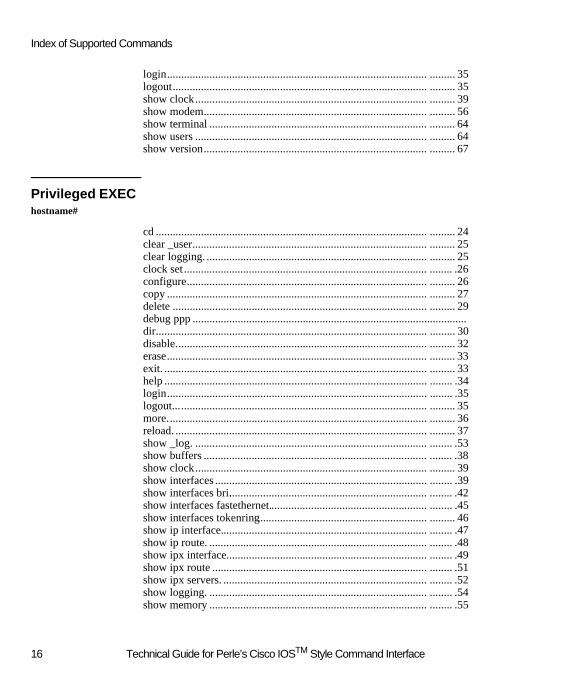
login............................................................................................ ......... 35logout.......................................................................................... ......... 35show clock.................................................................................. ......... 39show modem............................................................................... ......... 56show terminal ............................................................................. ......... 64show users .................................................................................. ......... 64show version............................................................................... ......... 67
Privileged EXEC hostname#
cd ................................................................................................ ......... 24clear _user................................................................................... ......... 25clear logging. .............................................................................. ......... 25clock set ...................................................................................... ........ .26configure..................................................................................... ......... 26copy ............................................................................................ ......... 27delete .......................................................................................... ......... 29debug ppp .................................................................................................dir................................................................................................ ......... 30disable......................................................................................... ......... 32erase............................................................................................ ......... 33exit. ............................................................................................. ......... 33help ............................................................................................. ........ .34login............................................................................................ ........ .35logout.......................................................................................... ......... 35more............................................................................................ ......... 36reload. ......................................................................................... ......... 37show _log. .................................................................................. ........ .53show buffers ............................................................................... ........ .38show clock.................................................................................. ......... 39show interfaces ........................................................................... ........ .39show interfaces bri....................................................................... ........ .42show interfaces fastethernet........................................................ ........ .45show interfaces tokenring............................................................ ......... 46show ip interface......................................................................... ........ .47show ip route. ............................................................................. ........ .48show ipx interface....................................................................... ........ .49show ipx route ............................................................................ ........ .51show ipx servers. ........................................................................ ........ .52show logging. ............................................................................. ........ .54show memory ............................................................................. ........ .55
16 Technical Guide for Perle’s Cisco IOSTM Style Command Interface

Technical Guide for Perle’s Cisco IOSTM Style Command Line Interface
show modem. ............................................................................. ........ .56show running-config................................................................... ........ .60show startup-config..................................................................... ......... 63show terminal ............................................................................. ........ .64show users. ................................................................................. ........ .64show version............................................................................... ........ .67terminal help............................................................................... ........ .69terminal history. ......................................................................... ........ .70terminal length. .......................................................................... ........ .71terminal width. ........................................................................... ........ .72undelete. ..................................................................................... ........ .72verify ............................................................................ ... .......... ........ .73
Global Configuration hostname(config)#
_assetid. ...................................................................................... ......... 75_axent-server. ............................................................................. ......... 75_axent-server spx-server............................................................. ......... 76_axent-server tcp-server.............................................................. ......... 77_bindery-server. ......................................................................... ......... 78_cardtype .................................................................................... ......... 79_database-access......................................................................... ....... ..81_frontpanel lock. ........................................................................ ....... ..83_frontpanel password.................................................................. ......... 84_group. ....................................................................................... ......... 84_nt-domain-server allow-user-specified-domain........................ ....... 105_nt-domain-server ip................................................................... ....... 105_nt-domain-server ipx................................................................. ....... 106_securid-server client-server-protocol........................................ ....... 111_securid-server encryption.......................................................... ....... 112_securid-server master-server..................................................... ....... 112_securid-server reset-node-secret................................................ ....... 113_securid-server slave-server........................................................ ....... 114_shared-database-server.............................................................. ....... 116_standard-profile......................................................................... ....... 120_userdb. ...................................................................................... ....... 121aaa authentication ppp................................................................. ......... 74banner motd................................................................................ ......... 78boot system flash......................................................................... ......... 79chat-script. .................................................................................. ......... 80enable secret ............................................................................... ......... 82
Technical Guide for Perle’s Cisco IOSTM Style Command Interface 17

Index of Supported Commands
end. ............................................................................................. ......... 83exit. ............................................................................................. ......... 33help. ............................................................................................ ......... 34hostname..................................................................................... ......... 85interface bri................................................................................. ........ .85 interface FastEthernet.................................................................. ......... 86interface TokenRing.................................................................... ......... 87ip _address user-database............................................................ ......... 89ip _dhcp-lease............................................................................. ......... 95ip _dhcp-reconnect-disable.......................................................... ......... 96ip _win-name-server.................................................................... ........ .94ip access-list extended................................................................. ......... 87ip address-pool... ........................................................................ ......... 88ip default gateway....................................................................... ......... 89ip dhcp-server ............................................................................. ......... 90ip local pool default..................................................................... ........ .91ip name-server. ........................................................................... ......... 92ip route........................................................................................ ........ .93ipx access-list extended............................................................... ......... 96ipx internal-network.................................................................... ......... 97ipx route...................................................................................... ......... 98ipx router rip. .............................................................................. ......... 99ipx routing. ................................................................................. ......... 99ipx sap......................................................................................... ....... 100isdn switch-type.......................................................................... ....... 163key chain..................................................................................... ....... 101line .............................................................................................. ....... 101logging buffered. ........................................................................ ....... 103radius-server deadtime................................................................ ....... 107radius server host......................................................................... ....... 107radius-server key......................................................................... ....... 108radius-server retransmit............................................................... ....... 109radius-server timeout................................................................... ....... 110router rip.. ................................................................................... ....... 111service password-encryption....................................................... ....... 115snmp-server chassis-id................................................................ ....... 117snmp-server community.............................................................. ...... .117snmp-server contact..................................................................... ..... ..118snmp-server host......................................................................... ..... ..119snmp-server location................................................................... ...... .120username..................................................................................... ....... 122
18 Technical Guide for Perle’s Cisco IOSTM Style Command Interface
Technical Guide for Perle’s Cisco IOSTM Style Command Line Interface
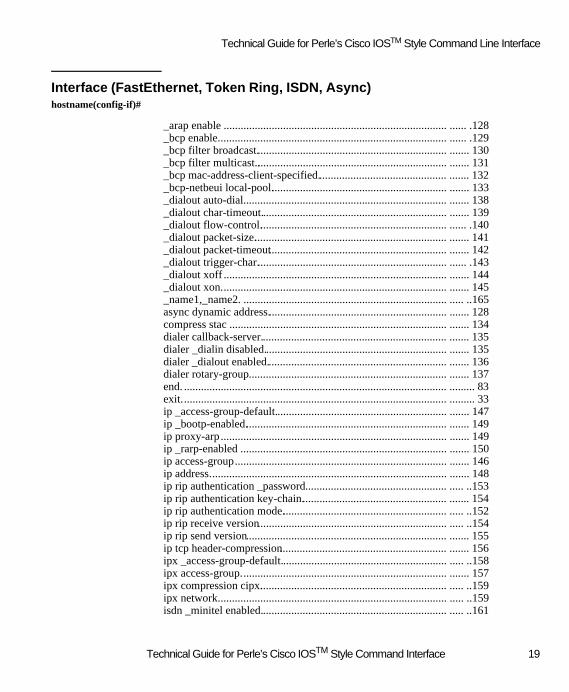
Interface (FastEthernet, Token Ring, ISDN, Async) hostname(config-if)#
_arap enable ............................................................................... ...... .128_bcp enable................................................................................. ...... .129_bcp filter broadcast.................................................................... ....... 130_bcp filter multicast..................................................................... ....... 131_bcp mac-address-client-specified.............................................. ....... 132_bcp-netbeui local-pool............................................................... ....... 133_dialout auto-dial........................................................................ ....... 138_dialout char-timeout.................................................................. ....... 139_dialout flow-control................................................................... ...... .140_dialout packet-size..................................................................... ....... 141_dialout packet-timeout............................................................... ....... 142_dialout trigger-char.................................................................... ...... .143_dialout xoff ............................................................................... ....... 144_dialout xon................................................................................ ....... 145_name1,_name2. ........................................................................ ..... ..165async dynamic address................................................................ ....... 128compress stac ............................................................................. ....... 134dialer callback-server.................................................................. ....... 135dialer _dialin disabled................................................................. ....... 135dialer _dialout enabled................................................................ ....... 136dialer rotary-group...................................................................... ....... 137end. ............................................................................................. ......... 83exit.............................................................................................. ......... 33ip _access-group-default............................................................. ....... 147ip _bootp-enabled........................................................................ ....... 149ip proxy-arp................................................................................ ....... 149ip _rarp-enabled ......................................................................... ....... 150ip access-group........................................................................... ....... 146ip address.................................................................................... ....... 148ip rip authentication _password.................................................. ..... ..153ip rip authentication key-chain.................................................... ....... 154ip rip authentication mode........................................................... ..... ..152ip rip receive version................................................................... ..... ..154ip rip send version....................................................................... ....... 155ip tcp header-compression........................................................... ....... 156ipx _access-group-default........................................................... ..... ..158ipx access-group......................................................................... ....... 157ipx compression cipx................................................................... ..... ..159ipx network................................................................................. ..... ..159isdn _minitel enabled.................................................................. ..... ..161
Technical Guide for Perle’s Cisco IOSTM Style Command Interface 19

Index of Supported Commands
isdn answer1, isdn answer 2........................................................ ....... 160isdn spid1.................................................................................... ....... 161isdn spid2.................................................................................... ....... 162isdn static-tei............................................................................... ....... 162isdn switch-type.......................................................................... ....... 163mac-address. ............................................................................... ....... 164media-type. ................................................................................. ....... 165netbios nbf. ................................................................................. ...... .166ppp _async-control...................................................................... ....... 168ppp authentication....................................................................... ...... .167ppp compression _address........................................................... ...... .168 ppp compression_protocol.......................................................... ....... 169ppp multilink .............................................................................. ....... 170ppp timeout retry ........................................................................ ....... 127ring-speed. .................................................................................. ....... 170shutdown. ................................................................................... ....... 171speed........................................................................................... ....... 171
IP Filter Configuration hostname(config-ip-ext-na)#
deny ............................................................................................ ....... 172exit. ............................................................................................. ......... 33permit.......................................................................................... ....... 173
IPX Filter Configuration hostname(config-ipx-ext-na)#
deny. ........................................................................................... ..... ..174exit. ............................................................................................. ......... 33permit.......................................................................................... ...... .175
Line Configuration hostname(config-line)#
exit. ............................................................................................. ........ .33modem _name. ........................................................................... ...... .179modem bad. ................................................................................ ...... .179script reset................................................................................... ....... 180
20 Technical Guide for Perle’s Cisco IOSTM Style Command Interface

Group Configuration
Group Configuration hostname(config-group)#
_bcp filter broadcast.................................................................... ...... .130_bcp filter multicast..................................................................... ....... 131_dialout auto-dial......................................................................... ....... 138_dialout char-timeout.................................................................. ...... .139_dialout flow-control................................................................... ..... ..140_dialout packet-size..................................................................... ...... .141_dialout packet-timeout............................................................... ....... 142_dialout trigger-char.................................................................... ....... 143_dialout xoff ............................................................................... ....... 144_dialout xon. ............................................................................... ....... 145_standard-profile......................................................................... ....... 120callback....................................................................................... ....... 123channels ...................................................................................... ..... ..124compress stac.............................................................................. ....... 134dialin.. ......................................................................................... ....... 125dialout. ........................................................................................ ....... 125exit. ............................................................................................. ........ .33ip tcp header-compression........................................................... ....... 156ipx compression cipx................................................................... ....... 159modems. ..................................................................................... ....... 126ppp _async-control...................................................................... ....... 168ppp compression _address........................................................... ....... 124ppp compression _protocol......................................................... ....... 169ppp timeout retry......................................................................... ....... 127
Standard Profile Configuration hostname(config-stdUser)#hostname(config-group-stdUser)#
Callback exclusive....................................................................... ....... 182Callback roaming........................................................................ ..... ..183Callback-rotary. .......................................................................... ...... .204exit. ............................................................................................. ....... ..33inactive. ...................................................................................... ..... ..184ip _access-group-default.............................................................. ....... 147
21 Technical Guide for Perle’s Cisco IOSTM Style Command Interface

Index of Supported Commands
ip access-group ........................................................................... ....... 146ipx _access-group-default............................................................ ....... 158ipx access-group. ........................................................................ ...... .157maximum.................................................................................... ..... ..186protocol....................................................................................... ..... ..187server-filters................................................................................ ....... 189virtual.......................................................................................... ....... 188
_userdb Configuration hostname(config-user)#
admin .......................................................................................... ....... 205department. ................................................................................. ....... 206disabled....................................................................................... ..... ..206exit. ............................................................................................. ........ .33expires. ....................................................................................... ....... 207override-standard-profile............................................................. ..... ..208
Key Chain Configuration hostname(config-key-chain)#
exit.. ............................................................................................ ......... 33key .............................................................................................. ....... 176
Router Configuation hostname(config-rr)#
exit.. ............................................................................................ ......... 33network....................................................................................... ....... 203
Key Configurationhostname(config-key-chain-key-id)#
accept-lifetime ............................................................................ ....... 176exit.. ............................................................................................ ....... ..33key-string.................................................................................... ....... 177send-lifetime............................................................................... ....... 177
22 Technical Guide for Perle’s Cisco IOSTM Style Command Interface

Override Standard Profile Configuration
Override Standard Profile Configurationhostname(config-user-override)#
Callback alternate........................................................................ ....... 181Callback roaming........................................................................ ....... 183exit.. ............................................................................................ ......... 33inactive. ...................................................................................... ....... 184ip _access-group-default.............................................................. ....... 147ip access-group. .......................................................................... ....... 146ip address .................................................................................... ....... 148ip tcp header-compression........................................................... ....... 156ipx _access-group-default............................................................ ...... .158ipx access-group. ........................................................................ ..... ..157ipx compressions ........................................................................ ....... 159l2l-auto-connect.......................................................................... ..... ..191l2l-calltype.................................................................................. ....... 194l2l-channel. ................................................................................. ....... 196l2l-id... ........................................................................................ ....... 192l2l-inactive.................................................................................. ....... 198l2l-minimum............................................................................... ....... 199l2l-password.. ............................................................................. ....... 193l2l-phone..................................................................................... ....... 195l2l-reconnect. .............................................................................. ....... 200l2l-rip send.................................................................................. ....... 201l2l-rip receive. ............................................................................ ....... 202l2l-virtual. ................................................................................... ....... 197lan-to-lan. ................................................................................... ....... 190macaddr ...................................................................................... ....... 185maximum.................................................................................... ....... 186protocol....................................................................................... ....... 187server-filters................................................................................ ....... 189virtual.......................................................................................... ....... 188
23 Technical Guide for Perle’s Cisco IOSTM Style Command Interface

Supported Command Set Definitions
Supported Command Set DefinitionsThe following Command Set includes all the Cisco and Perle commands that the 833IS supports. For an alphabetical list of all commands supported at each command level see Index of Supported Commands on page 15. Each command is described by the following format. Command: command name
Command description and function. Command descriptions use the following conventions:
Convention Description command font Command and keywords that are entered as shown< > Parameter value supplied by the user[ ] Optional parameter or keyword{ x | y | z } Select one of x or y or z.
Syntax Description: describes optional and required parameters for the com-mandDefault: default setting for the commandCommand Mode: level which the specific command is availableCommand Usage: description of command useExample: example use of commandRelated Commands: similar commands related by functionSample Display: display results
EXEC Mode
cd
Use this command to change the default file system.
cd <file system>
Syntax Description
Defaultflash:
Command ModeEXEC mode
Command UsageUse this command to change the default file system. For all file system commands that have an optional file system argument the default file system name is used.
file system This is the file system name to set as the new default
24 Technical Guide for Perle’s Cisco IOSTM Style Command Interface

EXEC Mode
Examplecd nvram:
!changes the default file system name to nvram: file system.
clear logging
To clear messages from the logging buffer, use the clear logging command.
clear logging
Syntax DescriptionNo parameters.
Command ModeEXEC
Command UsageThis command is used to clear the event log in the router.
Exampleclear logging
!clear the event log in the router
Related Commandslogging buffered
show logging
clear _user
To disconnect a user from the router. use the clear user command.
clear _user <username>
Syntax Description
Command ModeEXEC
Command UsageThis command disconnects an active user from the WAN interface. It does not clear active Telnet sessions.
Exampleclear _user user_01
! clears user "user_01".
username User to be disconnected
25 Technical Guide for Perle’s Cisco IOSTM Style Command Interface

Supported Command Set Definitions
clock set
To set the system clock on the router, use clock set command.
clock set <hh:mm:ss> <month> <day> <year>
Syntax Description
Command ModeEXEC configuration
Command UsageThis command is used to set the system clock on the router.
Exampleclock set 11:30:00 April 30 1999
!sets the system clock to 11:30 a.m. on April 30, 1999.
configure
To enter global configuration mode, use the configure command. You must be in this mode to enter global configuration com-mands.
configure
Syntax Description No parameters
Command ModeEXEC configuration
Command UsageTo enter any configuration commands you must first use this command to enter global configuration mode. Global com-mands can be entered in this mode or you can proceed to the other configuration modes (line, interface, etc.).
ExamplesIn the following example, a router is configured from the terminal:
router# configure
router(config)#
hh:mm:ss Current time in hours, minutes, and seconds.
day Current day (1-31) in the month.
month Current month (e.g. January, February, March, April, …)
year Current year (1970 - 2037)
26 Technical Guide for Perle’s Cisco IOSTM Style Command Interface

EXEC Mode
copy
To copy a file from a source to a destination use the copy command.
copy [<source file system>][<source host address>][<source file name>]
[<destination file system>][< destination host address >][< destination file name>]
Syntax Description
Command ModeEXEC mode
Command UsageThe copy command is used to copy a file from one file system to another. If the file system name is not supplied the current file system will be assumed. Use the CD command to change the current file system. If the source or destination filename or the tftp: address are left out then you will be prompted for this information. If the destination file system is a flash: file system then you will be prompted with the question "Erase file system before copying? ".
Some invalid combinations of source and destination exist. Specifically, you cannot copy:! From a running configuration to a running configuration.! From a startup configuration to a startup configuration.! From a device to the same device (for example, the copy flash: flash: command is invalid).
Some of the following prompt may be asked on a copy command:
Source filename [filename]?Type <CR> to confirm the destination filename or <CTRL-C> to abort the command or enter a new filename.
Destination filename [filename]?Type <CR> to confirm the destination filename or <CTRL-C> to abort the command or enter a new filename
Erase file system before copying?This question is only asked if the destination is a flash file system.Type <CR> or 'y' to proceed with the erase before copying the file or <CTRL-C> or 'n' to skip the erase before copying the file.
Erasing the file system filesystem will remove all files! Continue? [confirm].This question is asked to confirm that you really want to erase the flash file system.Type <CR> or 'y' to proceed with the erase before copying the file or <CTRL-C> or 'n' to skip the erase before copying the file.
Enter IP address or IPX address?This question is only asked if the source or destination file system is tftp:.Enter the IP address (format: xxx.xxx.xxx.xxx) for the tftp server orEnter the IPX address for the tftp server.format: nnnnnnnn:mmmmmmmmmmmmwhere nnnnnnnn is the network address and mmmmmmmmmmmm is the mac address
source file system This is the optional file system name for the source file
source host address This is the optional host address if the source file system is TFTP
source file name This is the optional source file name
destination file system This is the optional file system name for the destination file
destination host address This is the optional host address if the destination file system is TFTP
destination file name This is the optional destination file name
27 Technical Guide for Perle’s Cisco IOSTM Style Command Interface
Supported Command Set Definitions
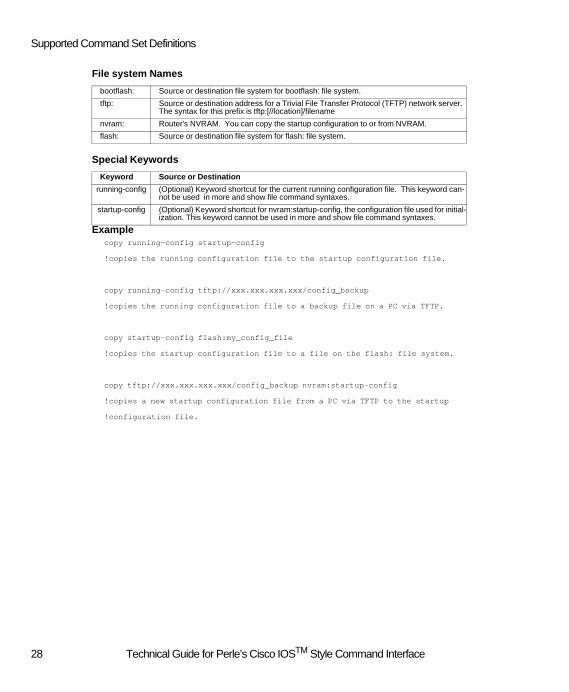
File system Names
Special Keywords
Examplecopy running-config startup-config
!copies the running configuration file to the startup configuration file.
copy running-config tftp://xxx.xxx.xxx.xxx/config_backup
!copies the running configuration file to a backup file on a PC via TFTP.
copy startup-config flash:my_config_file
!copies the startup configuration file to a file on the flash: file system.
copy tftp://xxx.xxx.xxx.xxx/config_backup nvram:startup-config
!copies a new startup configuration file from a PC via TFTP to the startup
!configuration file.
bootflash: Source or destination file system for bootflash: file system.
tftp: Source or destination address for a Trivial File Transfer Protocol (TFTP) network server. The syntax for this prefix is tftp:[//location]/filename
nvram: Router's NVRAM. You can copy the startup configuration to or from NVRAM.
flash: Source or destination file system for flash: file system.
Keyword Source or Destination
running-config (Optional) Keyword shortcut for the current running configuration file. This keyword can-not be used in more and show file command syntaxes.
startup-config (Optional) Keyword shortcut for nvram:startup-config, the configuration file used for initial-ization. This keyword cannot be used in more and show file command syntaxes.
28 Technical Guide for Perle’s Cisco IOSTM Style Command Interface

EXEC Mode
delete
Delete a file.
delete [<file system>]< file name>
Syntax Description
Command ModeEXEC mode
Command UsageUse this command to delete a file. When you delete a file on a flash: file system, the software simply marks the file as deleted, but it does not erase the file. This feature allows you to later recover a "deleted" file using the undelete command. You can delete and undelete a file up to 15 times. You will be prompted to confirm the deletion. If you use the delete command to delete a file on a non-flash file system (eg. nvram), the file is actually deleted and cannot be recovered with the undelete command.
Exampledelete my_config_file
!deletes the file my_config_file
debug ppp
Enable or disable various PPP debug information to the event log on the server.
[no] debug ppp {packet|negotiation|error|authentication|mp|cbcp}
Syntax Description
Command ModeEXEC mode
Command UsageUse the debug ppp EXEC command to display information on traffic and exhanges with the Point-to-Point Protocol (PPP). The no form of this command disables the debugging output. The output information is display in the event log on the server. By not specifying a specific option, all options are then enabled.
NOTE: By enabling debug ppp with several options, the server may experience a decrease in performance. This command should only be used to debug a particular connection and once completed should be disabled. Enabling this command can also quickly fill the event log on the server.
Example
file system This is the optional file system name for the source file.
file name This is the name of the file to be deleted.
packet Displays all ppp packets being transmitted and received
negotiation Displays PPP packets transmitted and received during PPP startup (PPP options are ne-gotiated i.e. LCP and NCP)
authentication Displays PPP authentication protocol messages
mp Display Multilink PPP protocol messages
cbcp Displays PPP callback (cbcp) protocol messages
error Displays protocol error and error statistics associated with PPP connection negotiation and operation.
29 Technical Guide for Perle’s Cisco IOSTM Style Command Interface
Supported Command Set Definitions
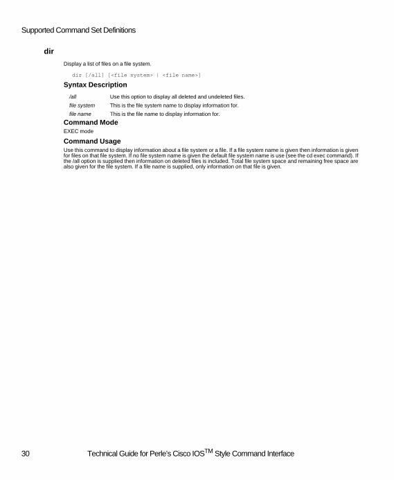
dir
Display a list of files on a file system.
dir [/all] [<file system> | <file name>]
Syntax Description
Command ModeEXEC mode
Command UsageUse this command to display information about a file system or a file. If a file system name is given then information is given for files on that file system. If no file system name is given the default file system name is use (see the cd exec command). If the /all option is supplied then information on deleted files is included. Total file system space and remaining free space are also given for the file system. If a file name is supplied, only information on that file is given.
/all Use this option to display all deleted and undeleted files.
file system This is the file system name to display information for.
file name This is the file name to display information for.
30 Technical Guide for Perle’s Cisco IOSTM Style Command Interface

EXEC Mode
Dir Field Descriptions
ExampleThe following example displays information for the flash: file system
router#dir /all flash:
Directory of flash:
1 arw- 1186970 Apr 03 2000 14:27:58 pcc-6600-s.img
2 arw- 60761 Apr 03 2000 14:28:10 file1
3 arw- 60761 Apr 03 2000 14:28:20 file2
4 arw- 60761 Apr 03 2000 14:28:26 file3
5 arw- 60761 Apr 03 2000 14:28:32 file4
6 arw- 2009 Apr 03 2000 14:53:38 [myfile.cfg]
7 arw- 2009 Apr 03 2000 15:02:22 myfile.cfg
8 arw- 29213 Apr 04 2000 14:32:24 [backup_config]
9 arw- 29152 Apr 04 2000 14:35:08 backup_config
10 arw- 1187001 Apr 05 2000 10:40:18 new_image
3389440 bytes total (2960896 bytes free)
Field Description
1 Index number of the file.
arw- Permissions. The file can be any or all of the following:
° a---archive(not used)
° r---readable
° w---writable
° h---hidden(not used)
1186970 Size of the file.
Apr 03 2000 14:27:58
Last modification date and time.
pcc-6600-s.img Filename. Deleted files are indicated by square brackets around the filename.
31 Technical Guide for Perle’s Cisco IOSTM Style Command Interface

Supported Command Set Definitions
disable
Use this command to return to the non-privileged EXEC mode from the privileged EXEC (enable) mode.
disable
Command ModeEXEC mode
Command UsageWhen the user returns to the non-privileged command mode it will be indicated by the angle bracket character (>) in the prompt.
Examplerouter#disable
router>
! return to the non-privileged EXEC mode.
enable
Use this command to enable privileged system commands.
enable
Command ModeEXEC mode
Command UsageUse this command to change to a privileged EXEC (enable) mode. If a password is configured for this mode you will be prompted to enter the password. The password is not displayed on the screen as it is entered. See the enable secret com-mand to define or remove the enable password. If no password is configured the user must have admin privileges to enter enable mode. If there is no password and the user does not have admin privileges the user will not be permitted to enter the enable mode. After the user enters the privileged command mode it will be indicated by the pound character (#) in the prompt. If the user is in the non-privileged command mode it will be indicated by the angle bracket character (>) in the prompt.
Examplerouter>enable
password:
router#
!change to enable mode.
Related Commandsenable secret
32 Technical Guide for Perle’s Cisco IOSTM Style Command Interface

EXEC Mode
erase
Use this command to erase a file system. All files are deleted and the file system is re-formated
erase <file system>
erase startup-config
Syntax Description
Command ModeEXEC mode
Command UsageUse this command to erase a file system. Files deleted with the delete command do not actually free up space in a flash file system. You must use the erase command to actually free up flash space. All files will be removed by the erase command and the file system will be re-formatted. Once erased, none of the files erased can be recovered. You can use the erase command to remove the startup-config file in two ways. Both do the same thing since startup-config is the only file allowed in the nvram: file system.
erase nvram:
erase startup-config
Examplerouter#erase flash:
Erasing the flash: file system will remove all files! Continue? [confirm] y
Erasing the flash: file system completed successfully.
! erases the flash: file system
exit
This command is used to exit any command mode.
exit
Syntax DescriptionNo parameters
Command ModeAvailable in all Command Modes
Command UsageThis command is used to exit any command mode. The exit command terminates an active session when executed from the privileged EXEC prompt.
Examplesrouter(config-if)# exit
!the user exits interface configuration mode and return
!to the global configuration mode,
file system This is the file system name for the file system to be erased.
startup-config This is the name of the startup-config file which will be erased.
33 Technical Guide for Perle’s Cisco IOSTM Style Command Interface

Supported Command Set Definitions
router(config)# exit
!then exits to the privileged EXEC mode,
router# exit
!and terminates the session.
Related Commandsend
help
Use the help command to get additional information in any command mode.
help
Syntax DescriptionNo parameters
Command ModeAll command modes.
Command UsageHelp may be requested at any point in a command by entering a question mark '?'. If nothing matches, the help list will be empty and you must backup until entering a '?' shows the available options.
Two styles of help are provided:
1. Full help is available when you are ready to enter a command argument (e.g. 'dialer ?') and describes each possible argu-ment.
2. Partial help is provided when an abbreviated argument is entered and you want to know what arguments match the input (e.g. 'dialer d?)
34 Technical Guide for Perle’s Cisco IOSTM Style Command Interface

EXEC Mode
login
Use this command to login to a session as a different user.
login
Command ModeEXEC mode
Command UsageUse this command to login to the current session as a different user. The username and password for the new user will be prompted for after the login command is entered. Once the login command is entered the current user is logged out and must enter a valid username and password to log back in. See the username and _userdb commands to define a user.
Usernames are case sensitive and may contain spaces. Leading spaces are ignored.
Username passwords are case sensitive and may contain spaces. Leading spaces are ignored.
Examplerouter>login
Username: newuser
Password:
! changes the current logged in user to the new user, as long as the correct password
! is provided.
logout
Use this command to logout the current user and to disconnect the current session.
logout
Command ModeEXEC mode
Command UsageUse this command to logout the current user and disconnect the current session.
Examplerouter>logout
Connection to host lost
!logs out the current use and disconnects the current session.
35 Technical Guide for Perle’s Cisco IOSTM Style Command Interface

Supported Command Set Definitions
more
Use this command to display a file.
more [/ascii | /binary] [<file system>][<file name>]
more [nvram:]startup-config
more running-config
Syntax Description
Command ModeEXEC mode
Command UsageUse this command to display a file. If the "/ascii" option is supplied the file is displayed as an ascii text file. If the /binary option is supplied the file is displayed in a binary hex format. If neither option is supplied then the system tries to auto detect the file type by looking at the first block of data. If any unprintable characters are encountered it is assumed to be a binary file. If the file name is not supplied it will be prompted for.
The more command can also be used to view the contents of the running-config and startup-config configuration files. When these files are displayed there are comments at the beginning of the files which tell you the last user that made changes to the configuration and the version number of the software that was used.
Examplerouter#more flash:test
test file line 1
test file line 2
test file line 3
test file line 4
last line of file test
! displays the text file called test
router#more startup-config
router#more running-config
!
! last config change at Thu Apr 6 09:05:35 2000 by perle
!
!version 07.00
/ascii Use this option to force the file to be displayed as an ascii text file
/binary Use this option to force the file to be displayed in binary hex format
file system This is the optional file system name for the file
file name This is the file name to be displayed
startup-config This is the file name for the startup-config file to be displayed
running-config This is the file name for the running-config file to be displayed
36 Technical Guide for Perle’s Cisco IOSTM Style Command Interface

EXEC Mode
!
no service password-encryption
isdn switch-type basic-net3
hostname perle
….
end
!displays the contents of the startup-config file or the running-config file
reload
To reload the firmware on a router use the reload command.
reload
Syntax Description No parameters
Command ModeEXEC mode
Command UsageThis command halts the router and reload the firmware image specified by the boot system flash command. If no filename is specified then loader searches the flash volume for a valid image file. If no valid image file can be found, the router boots with its Factory Default image located on the bootflash: volume.
Examples boot system flash PCC6600U.IMG
copy running-config startup-config
reload
!reloads the router with new firmware
Related Commands boot system flash
37 Technical Guide for Perle’s Cisco IOSTM Style Command Interface

Supported Command Set Definitions
show buffers
Use this command to obtain information about the number of buffers in the frames pool and the message pool.
show buffers
Command ModeEXEC mode
Command UsageStatistics for each pool show the total number of buffer in the pool, the lowest number of buffer the pool has been at and the current number of buffers left in the pool.
Sample DisplayThe following example displays the current buffer pool numbers.
router#show buffers
Messages (total) : 185
Messages (low) : 176
Messages (current): 183
Frames (total) : 500
Frames (low) : 381
Frames (current): 450
show buffers Field Descriptions
Field Description
Messages (total) Total number of message buffers in the router. Message buffers are used for control mes-sages
Messages (low) The low threshold for message buffers
Messages (current) Current number of message buffers in the router
Frames (total) Total number of frame buffers in the router. Frame buffers are used for data messages
Frames (low) The low threshold for frame buffers
Frames (current) Current number of frame buffers in the router
38 Technical Guide for Perle’s Cisco IOSTM Style Command Interface

EXEC Mode
show clock
Use the show clock command to display the system time.
show clock
SyntaxThis command has no arguments or keywords.
Command ModeEXEC
Sample DisplayThe following is sample output from the show clock command:
router#show clock
13:48:32 Wed Apr 05 2000
show interfaces
To display information about the router's physical interfaces, use the show interfaces command.
show interfaces
SyntaxThis command has no arguments or keywords.
Command ModeEXEC
Sample DisplayThe following is sample output from the show interfaces command. For a description of each field, please refer to the docu-mentation for show interfaces bri, show interfaces fastethernet and show interfaces tokenring.
Router#show interfaces
BRI0 is disconnected
In octets: 0
In discards: 0
In errors: 0
In unknown protocols: 0
Out octets: 0
Out discards: 0
Out errors: 0
BRI0:1 is disabled
Resource name: S1IF11
Capabilities: dialin/dialout/callback
39 Technical Guide for Perle’s Cisco IOSTM Style Command Interface

Supported Command Set Definitions
BRI0:2 is disabled
Resource name: S1IF12
Capabilities: dialin/dialout/callback
BRI1 is disconnected
In octets: 0
In discards: 0
In errors: 0
In unknown protocols: 0
Out octets: 0
Out discards: 0
Out errors: 0
BRI1:1 is disabled
Resource name: S1IF21
Capabilities: dialin
BRI1:2 is disabled
Resource name: S1IF22
Capabilities: dialin
BRI2 is disconnected
In octets: 0
In discards: 0
In errors: 0
In unknown protocols: 0
Out octets: 0
Out discards: 0
Out errors: 0
BRI2:1 is disabled
Resource name: S1IF31
Capabilities: none
BRI2:2 is disabled
Resource name: S1IF32
Capabilities: none
BRI3 is connected
In octets: 19599
In discards: 0
40 Technical Guide for Perle’s Cisco IOSTM Style Command Interface
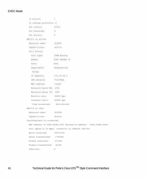
EXEC Mode
In errors: 1
In unknown protocols: 0
Out octets: 19731
Out discards: 0
Out errors: 0
BRI3:1 is active
Resource name: S1IF41
Capabilities: dialin
Call status:
Call type: ISDN Analog
Modem: S1M3 (Modem 3)
User: test
Department: Engineering
Group:
IP address: 172.16.56.3
IPX network: 75127B0A
MAC address: <none>
Resource bytes RX: 2351
Resource bytes TX: 1987
Receive rate: 26400 bps
Transmit rate: 26400 bps
Time connected: 00h:01m:43s
BRI3:2 is idle
Resource name: S1IF42
Capabilities: dialin
FastEthernet0 is connected
MAC address is 0040.028b.10f0 (burned in address - 0040.028b.10f0)
Port speed is 10 Mbps, connector is 10BaseT (RJ-45)
Bytes received: 60971193
Bytes transmitted: 1743066
Frames received: 371095
Frames transmitted: 18108
Overruns: 0
41 Technical Guide for Perle’s Cisco IOSTM Style Command Interface

Supported Command Set Definitions
show interfaces bri
Use the show interfaces bri command to display information about the router's BRI interfaces.
show interfaces bri <interface>[:channel | channel | channel end_channel ]
SyntaxDescription
Command ModeEXEC
Command UsageIf a channel number is not specified, show interfaces bri will display BRI interface statistics. To display BRI channel informa-tion, specify a channel number. If an ending channel number is also specified, information will be displayed for a range of BRI channels.
Sample DisplayThe following is sample output from the show interfaces bri command:
Router#show interfaces bri 3
BRI3 is connected
In octets: 1423
In discards: 0
In errors: 0
In unknown protocols: 0
Out octets: 1145
Out discards: 0
Out errors: 0
Router#show interfaces bri 3:1
BRI3:1 is active
Resource name: S1IF41
Capabilities: dialin
Call status:
Call type: ISDN Analog
Modem: S1M2 (Modem 2)
User: test
Department:
Group:
IP address: 172.16.56.3
interface Specifies a BRI interface. Valid interface numbers range from 0 to 7.
channel (Optional) Specifies a channel number. Valid channel numbers range from 1 to 2.
end_channel (Optional) Specifies an ending channel number. The ending channel number must be 2.
42 Technical Guide for Perle’s Cisco IOSTM Style Command Interface

EXEC Mode
IPX network: 4D3D65CB
MAC address: <none>
Resource bytes RX: 2383
Resource bytes TX: 4482
Receive rate: 26400 bps
Transmit rate: 24000 bps
Time connected: 00h:28m:31s
Router#show interface bri 0 1 2
BRI0:1 is disabled
Resource name: S1IF11
Capabilities: dialin/callback
BRI0:2 is disabled
Resource name: S1IF12
Capabilities: dialin/callback
show interfaces bri Field Descriptions (Interface statistics)
Field Description
BRI... is { connected | disconnected }
Indicates whether the interface hardware is currently active.
In octets Total number of bytes received by the D channel plus the total number of bytes received by each bearer channel. Bytes received on the bearer channels during analog calls are not counted.
In discards Number of received frames that were discarded. Buffer shortage is a possible reason for discarding received frames.
In errors Number of incoming frames that contained errors preventing them from being delivered to the link layer.
In unknown protocols Number of frames with a known TEI (Terminal Endpoint Identifier), but an unknown SAPI (Service Access Point Identifier.)
Out octets Total number of bytes transmitted by the D channel plus the total number of bytes trans-mitted by each bearer channel. Bytes transmitted on the bearer channels during analog calls are not counted.
Out discards Number of outbound frames that were discarded. Buffer shortage is a possible reason for discarding outbound frames.
Out errors Number of frames that could not be transmitted due to errors.
43 Technical Guide for Perle’s Cisco IOSTM Style Command Interface

Supported Command Set Definitions
show interfaces bri Field Descriptions (Channel statistics)
(*) - This field is only displayed for analog calls.
(**) - This field is only displayed for dial in calls.
Field Description
BRI... is { idle | connecting | con-nected | active | disabled }
Indicates the status of the channel.
Resource name Channel name
Capabilities Channel capabilities - any combination of dialin, dialout and callback capabilities, or none. If the channel that belongs to a group, this field will reflect the group capabilities. In this case, the capabilities configured for the channel will not be shown.
Call status This header and the following fields are only displayed when a call is present on the chan-nel.
Call type Type of call: ISDN Analog or ISDN Digital.
Modem (*) Name of the modem assigned to this channel, followed by the modem index in parenthe-ses.
User Name of user. Valid for dial in calls only.
Department (**) Name of the user's configured department.
Group If this channel has been assigned to a group, the group name is displayed here.
IP address (**) IP Address used by client - applicable only if IP has been negotiated for this connection.
IPX network (**) IPX Network number used by the client - applicable only if IPX has been negotiated for this connection.
MAC address (**) MAC Address used by the client.
Resource bytes Rx
For analog calls: the number of bytes received by the assigned modem since the unit was last reset.For digital calls: the number of bytes received by the bearer channel since the unit was last reset.
Resource bytes TX
For analog calls: the number of bytes transmitted by the assigned modem since the unit was last reset.For digital calls: the number of bytes transmitted by the bearer channel since the unit was last reset.
Receive rate For analog calls: the assigned modem's receive rate, in bits per second. For digital calls: the bearer channel's bandwidth (56000 bps or 64000 bps.)
Transmit rate For analog calls: the assigned modem's transmission rate, in bits per second.For digital calls: the bearer channel's bandwidth (56000 bps or 64000 bps.)
Time connected Elapsed time since the current call was established.
44 Technical Guide for Perle’s Cisco IOSTM Style Command Interface

EXEC Mode
show interfaces fasthethernet
Use the show interfaces fastethernet command to display information about the router's Fast Ethernet interface.
show interfaces fastethernet <interface>
SyntaxDescription
Command ModeEXEC
Command UsageThis command is only valid for units equipped with a Fast Ethernet interface.
Sample DisplayThe following is sample output from the show interfaces fastethernet command:
router#show interface fastethernet 0
FastEthernet0 is connected
MAC address is 0040.028b.10f0 (burned in address - 0040.028b.10f0)
Port speed is 10 Mbps, connector is 10BaseT (RJ-45)
Bytes received: 3264048
Bytes transmitted: 264457
Frames received: 19177
Frames transmitted: 3618
Overruns: 0
show interfaces fastethernet Field Description
interface Specifies a Fast Ethernet interface. Valid interface number is 0.
Field Description
FastEthernet... is { connected | discon-nected | administra-tively down }
Indicates whether the interface hardware is currently active or if it has been disabled by an administrator.
MAC address is... Configured hardware address of the interface, displayed as a triplet of four-digit hexadec-imal numbers.
Burned in address... Burned-in hardware address of the interface. This is the default hardware address.
Port speed is ... Current port speed in megabits per second
Connector is ... Cable type followed by the physical connector type in parentheses.
Bytes received Total number of bytes received by the interface since the unit was last reset.
Bytes transmitted Total number of bytes transmitted by the interface since the unit was last reset.
Frames received Total number of frames received by the interface since the unit was last reset.
Frames transmitted Total number of frames transmitted by the interface since the unit was last reset.
Overruns Number of times that heavy LAN traffic caused the interface to discard a frame. Overruns result in frames having to be retransmitted.
45 Technical Guide for Perle’s Cisco IOSTM Style Command Interface

Supported Command Set Definitions
show interfaces tokenring
Use the show interfaces tokenring command to display information about the unit's Token Ring interface.
show interfaces tokenring <interface>
SyntaxDescription
Command ModeEXEC
Command UsageThis command is only valid for routers equipped with a Token Ring interface.
Sample DisplayThe following is sample output from the show interfaces tokenring command:
router#show interfaces tokenring 0
TokenRing0 is connected
MAC address is 0040.028b.10f1 (burned in address - 0040.028b.10f1)
Port speed is 16 Mbps
Bytes received: 2604
Bytes transmitted: 521
Frames received: 4
Frames transmitted: 7
Overruns: 0
show interfaces tokenring Field Description
interface Specifies a Token Ring interface.Valid interface number is 0.
Field Description
TokenRing... is { connected | discon-nected | administra-tively down }
Indicates whether the interface hardware is currently active or if it has been disabled by an administrator.
MAC address is... Configured hardware address of the interface, displayed as a triplet of four-digit hexadec-imal numbers.
Burned in address... Burned-in hardware address of the interface. This is the default hardware address.
Port speed is ... Current port speed in megabits per second.
Bytes received Total number of bytes received by the interface since the unit was last reset.
Bytes transmitted Total number of bytes transmitted by the interface since the unit was last reset.
Frames received Total number of frames received by the interface since the unit was last reset.
Frames transmitted Total number of frames transmitted by the interface since the unit was last reset.
Overruns Number of times that heavy LAN traffic caused the interface to discard a frame. Overruns result in frames having to be retransmitted.
46 Technical Guide for Perle’s Cisco IOSTM Style Command Interface

EXEC Mode
show ip interface
To display a summary of an interface's IP information, use the show ip interface command.
show ip interface [ <type> <number> ]
SyntaxDescription
Command ModeEXEC
Command UsageThe fastethernet form of this command is only valid for units equipped with a Fast Ethernet interface. Likewise, the tokenring form of this command is only valid for units equipped with a Token Ring interface.
Sample DisplayThe following is sample output from the show ip interface command:
router#show ip interface
FastEthernet0 is connected
IP address is 172.16.56.2
Subnet mask is 255.255.0.0
IP address determined by configuration
Default gateway is 172.16.1.7
router#show ip interface fasthethernet 0
FastEthernet0 is connected
IP address is 172.16.56.2
Subnet mask is 255.255.0.0
IP address determined by configuration
Default gateway is 172.16.1.7
router#show ip interface tokenring 0
TokenRing0 is connected
IP address is 172.17.56.2
Subnet mask is 255.255.0.0
IP address determined by configuration
Default gateway is 172.17.1.7
type (Optional) Specifies that information is to be displayed for that interface type only. Valid types are fastethernet and tokenring.
number (Valid only if type is specified) Interface number.
47 Technical Guide for Perle’s Cisco IOSTM Style Command Interface

Supported Command Set Definitions
show ip interface Field Description
show ip route
To display the unit's IP routing table, use the show ip route command.
show ip route
Syntax Description This command has no arguments or keywords.
Command ModeEXEC
Sample DisplayThe following is sample output from the show ip route command:
router#show ip route
Key: User - User name for WAN router connection,
Fas - FastEthernet port, WAN - Wide Area Network port,
lpbk - loopback port, none - no port (disconnected route)
Default gateway address is 172.16.1.7
6 total IP routes
Destination Mask Gateway Hops Type Port User
----------- ---- ------- ---- ---- ---- ----
101.0.0.0 255.0.0.0 172.16.35.101 16 dynamic Fas0
127.0.0.1 255.255.255.255 0.0.0.0 0 static lpbk
172.16.0.0 255.255.0.0 0.0.0.0 1 static Fas0
172.16.56.2 255.255.255.255 0.0.0.0 0 static lpbk
192.168.0.0 255.255.255.0 172.16.5.11 4 dynamic Fas0
192.168.56.0 255.255.255.0 0.0.0.0 1 static WAN
Field Description
... is { connected | discon-nected | administratively down }
Indicates whether the interface hardware is currently active or if it has been disabled by an administrator.
IP address is ... Subnet mask is...
IP address and subnet mask assigned to this interface.
IP address determined by... Method by which the IP address was determined (configuration, BOOTP (Bootstrap Pro-tocol), RARP (Reverse Address Resolution Protocol), or default.)
Default gateway is.. Default gateway address configured for the unit.
48 Technical Guide for Perle’s Cisco IOSTM Style Command Interface
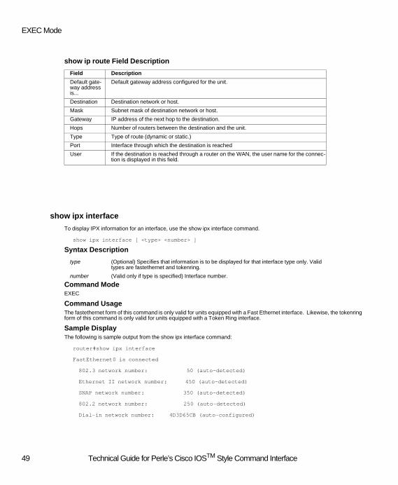
EXEC Mode
show ip route Field Description
show ipx interface
To display IPX information for an interface, use the show ipx interface command.
show ipx interface [ <type> <number> ]
Syntax Description
Command ModeEXEC
Command UsageThe fastethernet form of this command is only valid for units equipped with a Fast Ethernet interface. Likewise, the tokenring form of this command is only valid for units equipped with a Token Ring interface.
Sample DisplayThe following is sample output from the show ipx interface command:
router#show ipx interface
FastEthernet0 is connected
802.3 network number: 50 (auto-detected)
Ethernet II network number: 450 (auto-detected)
SNAP network number: 350 (auto-detected)
802.2 network number: 250 (auto-detected)
Dial-in network number: 4D3D65CB (auto-configured)
Field Description
Default gate-way address is...
Default gateway address configured for the unit.
Destination Destination network or host.
Mask Subnet mask of destination network or host.
Gateway IP address of the next hop to the destination.
Hops Number of routers between the destination and the unit.
Type Type of route (dynamic or static.)
Port Interface through which the destination is reached
User If the destination is reached through a router on the WAN, the user name for the connec-tion is displayed in this field.
type (Optional) Specifies that information is to be displayed for that interface type only. Valid types are fastethernet and tokenring.
number (Valid only if type is specified) Interface number.
49 Technical Guide for Perle’s Cisco IOSTM Style Command Interface

Supported Command Set Definitions
router#show ipx interface fastethernet 0
FastEthernet0 is connected
802.3 network number: 50 (auto-detected)
Ethernet II network number: 450 (auto-detected)
SNAP network number: 350 (auto-detected)
802.2 network number: 250 (auto-detected)
Dial-in network number: 4D3D65CB (auto-configured)
router#show ipx interface tokenring 0
Tokenring0 is connected
SNAP network number: 42 (auto-detected)
802.2 network number: 50 (auto-detected)
Dial-in network number: ADC389A6 (auto-configured)
show ipx interface Field Description
(*) - This field is only displayed when viewing IPX information for a Fast Ethernet interface.
Field Description
... is { connected | disconnect-ed | administratively down}
Indicates whether the interface hardware is currently active and if it has been disabled by an administrator.
802.3 network number (*) Network number for 802.3 (Novell-Ethernet) frames - may be configured or auto-detect-ed.
Ethernet II network number (*) Network number for Ethernet II (ARPA) frames - may be configured or auto-detected.
SNAP network number Network number for SNAP frames - may be configured or auto-detected.
802.2 network number Network number for 802.2 (SAP) frames - may be configured or auto-detected.
Dial-in network number Network number for unit's internal IPX network - may be configured or auto-configured.
50 Technical Guide for Perle’s Cisco IOSTM Style Command Interface

EXEC Mode
show ipx route
To display the contents of the IPX routing table, use the show ipx route command.
show ipx route
SyntaxThis command has no arguments or keywords.
Command ModeEXEC
Sample DisplayThe following is sample output from the show ipx route command:
router#show ipx route
8 total IPX routes
Network Hops Ticks
------- ---- -----
10 2 2
42 3 3
50 1 22
53 2 23
250 1 22
350 1 22
450 1 22
1212 2 2
show ipx route Field Description
Field Description
Network Destination network number.
Hops Number of routers between the destination network and the router's network.
Ticks Amount of time in ticks to reach the network (one tick is equal to 55 milliseconds.)
51 Technical Guide for Perle’s Cisco IOSTM Style Command Interface

Supported Command Set Definitions
show ipx servers
To display information about IPX servers discovered through Service Advertising Protocol (SAP) advertisements, use the show ipx servers command.
show ipx servers [ unsorted | { sorted [ name | net | type ] } ]
SyntaxDescription
Command ModeEXEC
Command UsageUsage examples:
Display the server list in default order:
router#show ipx servers
Display the server list in internal order:
router#show ipx servers unsorted
Display the server list in sorted order (by default sorting criteria):
router#show ipx servers sorted
Display the server list in sorted order (by type):
router#show ipx servers sorted type
DefaultIf no arguments are specified, server entries are sorted alphabetically by server name.
Sample DisplayThe following is sample output from the show ipx servers command:
router#show ipx servers
10 total IPX servers
Server Name Type Hops Network Node Address Socket
----------- ---- ---- ------- ------------ ------
0060B025AAC600CR 30C 4 A00AB00B.0060.b025.aac6:400C
00902709023106SU 3FB 4 42.0090.2709.0231:87B8
1CALL 640 4 A00AB00B.0060.97bc.8731:E885
unsorted (Optional) Display the server list in internal order.
sorted (Optional) Display the server list in sorted order.
name (Optional) Sort the server list alphabetically by server name. This is the default.
net (Optional) Sort the server list numerically by network number.
type (Optional) Sort the server list numerically by SAP service type.
52 Technical Guide for Perle’s Cisco IOSTM Style Command Interface

EXEC Mode
AR00211064PERLE 44C 3 3111A675.0000.0000.0001:8600
AS9NX399SUPPORT 44C 3 A00A.0000.0000.0001:8600
COMMUNICATIONS 67B 4 A00AB00B.0010.5a9c.e57d:0555
COMPAQ 640 2 250.0080.5fed.3aaf:E885
MARKETING 67B 4 A00AB00B.0040.c75a.655b:0555
SUPPORT 107 3 A00A.0000.0000.0001:8104
WORKGROUP 67B 2 50.00c0.a829.d76e:0555
show ipx servers Field Description
show _log
Use this command to obtain information about any errors that may have occurred while processing configuration or default files.
show _log
Command ModeEXEC mode
Command UsageDuring initialization any errors that are encountered while processing the startup-config file or the default-config file are add-ed to this error log. In addition any errors encountered while copying a file to running-config will also go in this log. This error log is kept in dynamic memory and is therefore reset whenever the router is re-booted.
Sample DisplayThe following example displays the current configuration error log.
router#copy tftp://xxx.xxx.xxx.xxx/bad.cfg running-config
router#show _log
Tftp: Unrecognized command (this is a bad command )
Field Description
Server name Name of the server.
Type SAP service type, displayed as a hexadecimal number. Service type values are defined by Novell (e.g. 4 - File server, 7 - Print server.)
Hops Number of routers between the server and the router.
Network Network on which the server is located.
Node address Node address of the server, displayed as a triplet of 4-digit hexadecimal numbers.
Socket Source socket number, displayed in hexadecimal.
53 Technical Guide for Perle’s Cisco IOSTM Style Command Interface

Supported Command Set Definitions
show logging
Use this command to obtain a display of the current event log.
show logging
Command ModeEXEC mode
Command UsageEvent messages are displayed with the most current message first.
Sample DisplayThe following example displays the current event log.
hostname# show logging
Buffer logging: level debugging, 105 messages logged
Trap logging: level informational, 18 messages logged
Apr 07 08:22:23 vty Port: 18 Logoff newuser/
Apr 06 15:46:53 vty Port: 18 Valid user logon newuser/
0/06:51-V07.00G-B01.10- hostname
Apr 06 15:46:50 vty Port: 18 Invalid password user2/
Apr 06 15:46:29 vty Port: 18 Invalid password user2/
Apr 06 15:41:44 vty Port: 18 Invalid password user2/
Apr 06 15:10:49 vty Port: 18 Logoff perle/
Apr 06 15:08:15 vty Port: 18 Valid user logon perle/
0/06:13-V07.00G-B01.10-hostname
54 Technical Guide for Perle’s Cisco IOSTM Style Command Interface

EXEC Mode
show memory
Use this command to obtain information about available memory in the router.
show memory
Command ModeEXEC mode
Command UsageInformation displayed includes statistics about total memory and free memory at the time the command is executed. This command applies to the heap memory which is allocated and deallocated dynamically by the router
Sample DisplayThe following example displays the current memory statistics.
router#show memory
Smallest free block : 52 (0x34)
Largest free block : 183360 (0x2CC40)
Total free blocks : 69 (0x45)
Total memory blocks : 2027 (0x7EB)
Total free memory : 188304 (0x2DF90)
Total memory : 8388608 (0x800000)
show memory Field Descriptions
Field Description
Smallest free block The smallest block of free memory available in the heap.
Largest free block The largest block of free memory available in the heap.
Total free blocks Total number of memory blocks in the heap
Total memory blocks
Total number of memory blocks in the router (allocated + free)
Total free memory Total free memory in the heap available for allocation
Total memory Total dynamic memory in the router (allocated + free)
55 Technical Guide for Perle’s Cisco IOSTM Style Command Interface

Supported Command Set Definitions
show modem
Use the show modem command to display modem statistics and information.
show modem [ index ]
SyntaxDescription
Command ModeEXEC
Command UsageThis command is only valid for units equipped with modems. If a modem index is not specified, summarized information for all modems will be displayed. To display detailed modem information, specify a modem index.
Sample DisplayThe following is sample output from the show modem command:
router#show modem
Key: Assigned - Assigned BRI channel/modem status,
Attmpt - Incoming attempts, Cmpltn - Incoming completions,
Fail - Incoming failures, Rtrn - Retrains
Mdm Name Assigned Attmpt Cmpltn Fail Bytes RX Bytes TX Rtrn
--- ---- -------- ------ ------ ---- -------- -------- ----
1 S1M1 <Idle> 1 1 0 2855 2053 0
2 S1M2 S1IF41 1 1 0 2350 1891 0
3 S1M3 <Idle> 0 0 0 528 104 0
4 S1M4 <Idle> 0 0 0 528 104 0
5 S1M5 <Idle> 0 0 0 528 104 0
6 S1M6 <Idle> 0 0 0 528 104 0
7 S1M7 <Idle> 0 0 0 528 104 0
8 S1M8 <Idle> 0 0 0 528 104 0
router#show modem 1
Modem 1, TTY1
Name: S1M1
Status: Idle
Incoming attempts: 1
Incoming completions: 1
Incoming failures: 0
Bytes received: 2855
index (Optional) Specifies a modem. The valid range for modem indices is 1 to 16.
56 Technical Guide for Perle’s Cisco IOSTM Style Command Interface

EXEC Mode
Bytes transmitted: 2053
Retrains: 0
Last call:
Modem modulation: ITU V.34
Receive rate: 26400 bps
Transmit rate: 26400 bps
router#show modem 2
Modem 2, TTY2
Name: S1M2
Status: Active
Incoming attempts: 1
Incoming completions: 1
Incoming failures: 0
Bytes received: 2350
Bytes transmitted: 1891
Retrains: 0
Current call:
Modem modulation: ITU V.34
Receive rate: 26400 bps
Transmit rate: 24000 bps
Call status:
Assigned channel: S1IF41 (BRI3:1)
User: test
Department: Engineering
Group:
IP address: 172.16.56.3
IPX network: 4D3D65CB
MAC address: <none>
Time connected: 00h:08m:41s
57 Technical Guide for Perle’s Cisco IOSTM Style Command Interface

Supported Command Set Definitions
show modem Field Descriptions (summary)
show modem Field Descriptions (detailed)
Field Description
Mdm Modem index.
Name Name of modem.
Assigned If a call is present on the modem, this field displays the name of the assigned BRI line resource (bearer channel). Otherwise, this field displays the modem's status (Idle, Failed, or Disabled.)
Attmpt Total number of incoming connection attempts for the modem since the unit was last re-set.
Cmpltn Number of successfully completed incoming connection attempts for the modem since the unit was last reset.
Fail Number of failed incoming connection attempts for the modem since the unit was last re-set.
Bytes Rx Number of bytes received by the modem since the unit was last reset.
Bytes Tx Number of bytes transmitted by the modem since the unit was last reset.
Retrn Number of retrains experienced on connections with the modem since the unit was last reset.
Field Description
Modem ... Modem index.
TTY ... Index of associated Terminal Controller resource.
Name Name of specified modem.
Status Modem status (Active, Idle, Failed, or Disabled.)
Incoming at-tempts
Total number of incoming connection attempts for the specified modem since the unit was last reset.
Incoming comple-tions
Number of successfully completed incoming connection attempts for the specified mo-dem since the unit was last reset.
Incoming failures Number of failed incoming connection attempts for the specified modem since the unit was last reset.
Bytes received Number of bytes received by the specified modem since the unit was last reset.
Bytes transmitted Number of bytes transmitted by the specified modem since the unit was last reset.
Retrains Number of retrains experienced on connections with the specified modem since the unit was last reset.
Last/Current Call
Modem modula-tion
Last known modulation scheme used by the specified modem (e.g. ITU V.34, ITU v.90, etc.)
Receive rate Last known receive rate for the specified modem, in bits per second.
Transmission rate
Last known transmission rate for the specified modem, in bits per second.
Call status This header and the following fields are only displayed when a call is active on the speci-fied modem.
User User's name. Valid for dial in calls only.
Department (*) Name of the user's configured department.
58 Technical Guide for Perle’s Cisco IOSTM Style Command Interface

EXEC Mode
(*) - This field is only displayed for dial in calls.
Group If the current call is associated with a group, the group name is displayed here.
IP address (*) IP Address used by the client - applicable only if IP has been negotiated for this connec-tion.
IPX network (*) IPX network number used by the client - applicable only if IPX has been negotiated for this connection.
MAC address (*) MAC Address used by the client.
Assigned Channel
Name of the BRI line resource (bearer channel) used for this call, followed by the BRI in-terface and channel index in parenthesis.
Time connected Elapsed time since call was established.
59 Technical Guide for Perle’s Cisco IOSTM Style Command Interface

Supported Command Set Definitions
show running-config
To display the contents of the unit’s running configuration file, use the show running-config command.
show running-config
SyntaxThis command has no arguments or keywords.
Command ModeEXEC
Command UsageEntering this command is equivalent to issuing more running-config from the EXEC level.
Sample DisplayThe following is a sample output from the command show running-config:
router#show running-config
! last config change at Thu Apr 20 12:00:31 2000 by user1
!<prolog>
!version 07.00
!<config>
no service password-encryption
ip default-gateway 101.104.101.1
ipx routing
isdn switch-type basic-ni1
ip _dhcp-lease 65535
username user1 password 0 user 1
username user2 password 0 user 2
ipx internal-network 1111
hostname router
60 Technical Guide for Perle’s Cisco IOSTM Style Command Interface

EXEC Mode
username me
boot system flash pcc6600s.img
!<group-async 0>
interface group-Async 0
!<dialer 0>
interface dialer 0
!<StdProfile>
_standard-profile
!<interface FastEthernet 0>
interface FastEthernet 0
ip address 101.104.88.111 255.255.0.0
ipx network _auto-detected encapsulation arpa
ipx network _auto-detected encapsulation snap
ipx network _auto-detected encapsulation sap
ipx network _auto-detected encapsulation novell-ether
!<interface TokenRing 0>
!<interface bri 0>
interface bri 0
shutdown
!<interface bri 1>
interface bri 1
shutdown
!<interface bri 2>
interface bri 2
shutdown
!<interface bri 3>
interface bri 3
shutdown
!<interface bri 4>
interface BRI 4
!<interface bri 5>
!<interface bri 6>
!<interface bri 7>
!<User user1>
_userdb user1
61 Technical Guide for Perle’s Cisco IOSTM Style Command Interface

Supported Command Set Definitions
admin
!<User user2>
_userdb user2
admin
!!Override test>
override-standard-profile
!<User>
!<RouterRip>
router rip
!<KeyChain test>
key chain test
key chain test
!<line 1 16>
line 1 16
!<User user1>
_userdb user1
admin
!<User test>
_userdb test
!!Override test>
override-standard-profile
!<User>
!<RouterRip>
router rip
!<KeyChain test>
key chain test
key chain test
!<line 1 16>
line 1 16
!<group test>
_group test
!!stdUser test>
_standard-profile
!<end>
end
62 Technical Guide for Perle’s Cisco IOSTM Style Command Interface

EXEC Mode
show startup-config
To display the contents of the unit's startup configuration file, use the show startup-config command.
show startup-config
SyntaxThis command has no arguments or keywords.
Command ModeEXEC
Command UsageEntering this command is equivalent to issuing more nvram:startup-config from the EXEC level.
Sample DisplayThe following is sample output from the show startup-config command:
router#show startup-config
!
! last config change at Tue Apr 4 15:24:51 2000 by dave
!version 07.00
isdn switch-type basic-dms100
hostname Router
banner motd gPerle 833ISg
ipx routing
no service password-encryption
ip default-gateway 172.16.1.7
ipx router rip
boot system flash pcc6600s.img
end
63 Technical Guide for Perle’s Cisco IOSTM Style Command Interface

Supported Command Set Definitions
show terminal
Use this command to obtain information about the current terminal session parameter settings.
show terminal
Command ModeEXEC mode
Command UsageUse this command to determine the settings for the current terminal session.
Sample DisplayThe following example displays the current terminal settings.
router>show terminal
Terminal length = 24
Terminal width = 80
Terminal history is enabled
Terminal history size = 30
show users
To display information about WAN-connected users, use the show users command.
show users [ <partial_name> ]
Syntax Description partial_name (Optional) Specify a partial user name.
Command ModeEXEC
Command UsageThis command does not display users that are connected to VTY ports. If a partial name is not specified, summarized infor-mation regarding all users will be displayed. To display detailed information about specific users, specify a partial user name.
Usage examples:
Display summarized information about all WAN users:
router#show users
Display detailed information about all WAN users whose names begin with "A":
router#show users A
Display detailed information about all WAN users:
router#show users ""
64 Technical Guide for Perle’s Cisco IOSTM Style Command Interface

EXEC Mode
Sample DisplayThe following is sample output from the show users command:
router#show users
User Call Type Channel Modem RX Rate TX Rate
---- --------- ------- ----- ------- -------
test ISDN Analog S1IF41 S1M2 26400 bps 24000 bps
test2 ISDN Analog S1IF42 S1M3 26400 bps 24000 bps
router#show users t
User: test
Department: Engineering
Group:
IP address: 172.16.56.3
IPX network: 4D3D65CB
MAC address: <none>
Resource bytes RX: 2383
Resource bytes TX: 4482
Receive rate: 26400 bps
Transmit rate: 24000 bps
Call type: ISDN Analog
Channel: S1IF41 (BRI3:1)
Modem: S1M2 (Modem 2)
Time connected: 00h:26m:15s
User: test2
Department: Engineering
Group:
IP address: 192.168.56.2
IPX network: 4D3D65CB
MAC address: <none>
Resource bytes RX: 2182
Resource bytes TX: 465
Receive rate: 26400 bps
Transmit rate: 24000 bps
Call type: ISDN Analog
Channel: S1IF42 (BRI3:2)
Modem: S1M3 (Modem 3)
65 Technical Guide for Perle’s Cisco IOSTM Style Command Interface
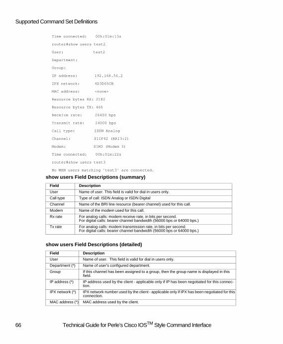
Supported Command Set Definitions
Time connected: 00h:01m:13s
router#show users test2
User: test2
Department:
Group:
IP address: 192.168.56.2
IPX network: 4D3D65CB
MAC address: <none>
Resource bytes RX: 2182
Resource bytes TX: 465
Receive rate: 26400 bps
Transmit rate: 24000 bps
Call type: ISDN Analog
Channel: S1IF42 (BRI3:2)
Modem: S1M3 (Modem 3)
Time connected: 00h:01m:22s
router#show users test3
No WAN users matching 'test3' are connected.
show users Field Descriptions (summary)
show users Field Descriptions (detailed)
Field Description
User Name of user. This field is valid for dial in users only.
Call type Type of call: ISDN Analog or ISDN Digital
Channel Name of the BRI line resource (bearer channel) used for this call.
Modem Name of the modem used for this call.
Rx rate For analog calls: modem receive rate, in bits per second. For digital calls: bearer channel bandwidth (56000 bps or 64000 bps.)
Tx rate For analog calls: modem transmission rate, in bits per second. For digital calls: bearer channel bandwidth (56000 bps or 64000 bps.)
Field Description
User Name of user. This field is valid for dial in users only.
Department (*) Name of user's configured department.
Group If this channel has been assigned to a group, then the group name is displayed in this field.
IP address (*) IP address used by the client - applicable only if IP has been negotiated for this connec-tion.
IPX network (*) IPX network number used by the client - applicable only if IPX has been negotiated for this connection.
MAC address (*) MAC address used by the client.
66 Technical Guide for Perle’s Cisco IOSTM Style Command Interface

EXEC Mode
(*) - This field is displayed for dial in users only.
(**) - This field is displayed for analog calls only.
show version
To display information about the unit's version and resources, use the show version command.
show version
Syntax Description This command has no arguments or keywords.
Command ModeEXEC
Sample DisplayThe following is sample output from the show version command:
router#show version
Perle 833IS Remote Access Server
Copyright (c) 1994-2000 Perle Systems Limited and its Suppliers.
Server name: Router
Asset ID: Lab215
Firmware version: 07.00G
BIOS version: 01.10
Server start time: 16:29:48 Tue Apr 04 2000
The server has been up for 17 hours and 31 minutes.
System image file is 'flash:pcc6600u.img'.
Resource bytes Rx
For analog calls: number of bytes received by the modem since the unit was last reset.For digital calls: number of bytes received by the bearer channel since the unit was last reset.
Resource bytes Tx
For analog calls: number of bytes transmitted by the modem since the unit was last reset.For digital calls: number of bytes transmitted by the bearer channel since the unit was last reset.
Receive rate For analog calls: modem receive rate, in bits per second.For digital calls: bearer channel bandwidth (56000 bps or 64000 bps.)
Transmit rate For analog calls: modem transmission rate, in bits per second.For digital calls: bearer channel bandwidth (56000 bps or 64000 bps.)
Call type Type of call: ISDN Analog or ISDN Digital.
Channel Name of the BRI line resource (bearer channel) used for this call, followed by the BRI in-terface and channel index in parentheses.
Modem (**) Name of the modem used for this call, followed by the modem index in parentheses.
Time connected Elapsed time since call was established.
67 Technical Guide for Perle’s Cisco IOSTM Style Command Interface

Supported Command Set Definitions
Resources:
Interface Total Enabled In Use
--------- ----- ------- ------
FastEthernet 1 1 1
BRI S/T 8 2 1
Perle DSP 8 8 1
show version Field Description
Field Description
Server name Name configured for the unit. The server name is used to identify the unit to the network (e.g. the server name appears in SAP advertisements, if IPX is configured for the unit.)
Asset ID Asset ID configured for the unit. The Asset ID is used for reference only.
Firmware version Version number of the unit's operating firmware.
BIOS version Version number of the unit's BIOS.
Server start time Date and time that the unit was last reset.
The server has been up for...
Elapsed time since the unit was last reset.
System image file is...
Name of the currently loaded system image file.
Resources Resource information appears beneath this header.
Interface Name of an interface that is present on the unit. The relationship between physical inter-faces and resources is as follows:
FastEthernet - the physical interface is counted as a resource.
TokenRing - the physical interface is counted as a resource.
BRI S/T or BRI U - each bearer channel is counted as a resource. There-fore, two resources will be counted for each physical BRI interface.
Perle DSP (modems) - each modem is counted as a resource.
Total Total number of resources for the current interface type.
Enabled Number of enabled resources for the current interface type.
In use Number of active resources for the current interface type.
68 Technical Guide for Perle’s Cisco IOSTM Style Command Interface

EXEC Mode
terminal help
Use this command to display a description of the help system.
terminal help
Command ModeEXEC mode
Command UsageUse this command to display a description of the terminal help system.
Examplerouter#terminal help
!displays a description of the help system.
Help may be requested at any point in a command by entering a question mark '?'. If nothing matches, the help list will
be empty and you must backup until entering a '?' shows the available options. Two styles of help are provided:
1. Full help is available when you are ready to enter a command argument (e.g. 'dialer ?') and describes each possible
argument.
2. Partial help is provided when an abbreviated argument is entered and you want to know what arguments match the input
(e.g. 'dialer c?'.)
69 Technical Guide for Perle’s Cisco IOSTM Style Command Interface

Supported Command Set Definitions
terminal history
Use this command to enable and disable the terminal history option and to set the size of the terminal history buffer.
terminal history [size] [<size>]
terminal no history [size] [<size>]
Syntax Description
Default30 Lines, history enabled
Command ModeEXEC mode
Command UsageUse this command without the optional <size> to enable and disable the terminal history option. Disabling the history option will not effect the size of the history buffer. If the <size> argument is specified then this command will set the size in lines of the terminal history buffer. The valid ranges for the history buffer size is 0 to 256 lines. The terminal history command pro-vides a record of commands you have entered.
History Keys
Exampleterminal history
!enable the terminal history option.
terminal no history
!disable the terminal history option
terminal history size 50
!set the terminal history buffer size to 50 lines.
terminal no history size
!reset the terminal history buffer size back to its default value (30 lines)
size This optional argument specifies the number of lines to maintain in the terminal history buffer.
Key Function
Ctrl-P or up arrow Recalls commands in the history buffer in a backward sequence, beginning with the most recent command. Repeat the key sequence to recall successively older commands.
Ctrl-N or down arrow Returns to more recent commands in the history buffer after recalling commands with Ctrl-P or the up arrow. Repeat the key sequence to recall successively more recent com-mands.
70 Technical Guide for Perle’s Cisco IOSTM Style Command Interface

EXEC Mode
terminal length
Use this command to set the number of lines on your terminal screen for the current active session.
terminal length <length>
terminal no length
Syntax Description
Default24 lines
Command ModeEXEC mode
Command UsageThe system uses this number to determine where to pause when displaying long output screens. When the output reaches the displayed lines it will pause until the user responds to let it continue. Use a length of zero to have the system not pause between output screens. Use the no version of the command to reset the terminal length back to its default value. The valid range for the terminal length is 0 to 512 lines.
Exampleterminal length 30
!set the terminal length to 30 lines between pauses.
terminal length 0
!tell the terminal not to pause.
terminal no length
!reset the terminal length back to its default value (24).
length This argument specifies the number of line to display on the current active session
71 Technical Guide for Perle’s Cisco IOSTM Style Command Interface

Supported Command Set Definitions
terminal width
Use this command to set the number of character columns on your terminal screen for your current active session.
terminal width <width>
terminal no width
Syntax Description
Default80 Characters
Command ModeEXEC mode
Command UsageUse this command to set the number of character columns to display on your terminal screen for the current active session. The system uses this number to determine where to break up long lines of output on your terminal screen. Line will not be broken up in the middle of words in the display. Use the no version of the command to reset the terminal length back to its default value.
The valid range for the terminal width is 0 to 512 character columns.
Exampleterminal width 132
!set the terminal width to 132 character columns.
terminal no width
!reset the terminal width back to its default value (80).
undelete
Use this command to recover a deleted file in a flash: file system.
undelete <fileno> <file system>
Syntax Description
Command ModeEXEC mode
Command UsageUse this command to recover a previously deleted file. This command will only work in a flash: file system. When a file is deleted in a flash: file system the file is only marked as deleted and not actually removed. This allows the ability to recover these files. The file index number, not the file name is supplied. Use the dir command to find the file index number. A file may be deleted and undeleted up to 15 times. If you undelete a file with a file name that already exists as an undeleted file then that file is first deleted before the file specified in the undelete command is recovered.
Exampleundelete 5 flash:
!recovers file number 5 in the flash: file system.
width This argument specifies the number of character columns to display on your current ac-tive session.
fileno This is the file number of the deleted flash: file to be recovered
file system This is the file system name for the file
72 Technical Guide for Perle’s Cisco IOSTM Style Command Interface
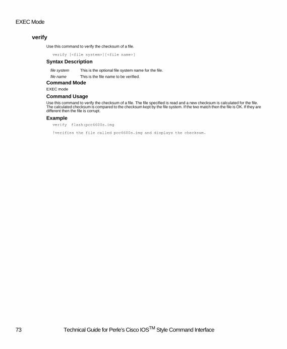
EXEC Mode
verify
Use this command to verify the checksum of a file.
verify [<file system>][<file name>]
Syntax Description
Command ModeEXEC mode
Command UsageUse this command to verify the checksum of a file. The file specified is read and a new checksum is calculated for the file. The calculated checksum is compared to the checksum kept by the file system. If the two match then the file is OK. If they are different then the file is corrupt.
Exampleverify flash:pcc6600s.img
!verifies the file called pcc6600s.img and displays the checksum.
file system This is the optional file system name for the file.
file name This is the file name to be verified.
73 Technical Guide for Perle’s Cisco IOSTM Style Command Interface

Supported Command Set Definitions
Global Configuration
aaa authentication ppp
This command is used to define the type of security method used to authenticate dial-in clients. The "no" or "default" version of the command will set the security method to "local".
aaa authentication ppp default <security method>
no aaa authentication ppp default
default aaa authentication ppp default
Syntax Description
Default"local" security
Command ModeGlobal configuration
Command UsageThis command sets the security method used to authenticate ppp, dial-in users. If local is used, the user may be authenticat-ed from the local database or from another router defined using the SUL (Shared User List) feature. Additional configuration may be required for each of the above security methods.
Exampleaaa authentication ppp default radius
! ppp dial-in users will be authenticated using a radius server
no aaa authentication ppp default
! ppp dial-in users will be authenticated using the internal
! local database
Related Commandsradius-server
ppp authentication
_bindery-server
_securid-server
_axent-server
_database-access
_shared-database-server
Security method Type of security used to authenticate the dial-up clients. The following types of security methods are supported. local internal data base radius Remote Authentication Dial-In Users Services _bindery Netware Bindery _nt-domain Windows NT _securid Security Dynamics _axent (also known as Assurenet or Digital Pathways)
74 Technical Guide for Perle’s Cisco IOSTM Style Command Interface

Global Configuration
_assetid
To specify the assetid for a router use the _assetid command. Use the no form of this command to delete the _assetid
_assetid <asset-id>
no _assetid
Syntax Description
DefaultThe asset id is not defined.
Command ModeGlobal configuration
Command UsageThis command is used to display a tracking identifier such as the serial number of the router.
Example_assetid SN012345567
!defines an asset id of SN012345567 for the router
_axent-server
This command is used to configure the parameters associated with an Axent security server.
_axent-server <protocol> <key> <id>
no _axent-server <protocol>
Syntax Description
DefaultNone.
Command ModeGlobal configuration
Command UsageThis command is used to configure some of the parameters used when an Axent security server is used. The protocol, agent key and agent id must match with the configuration on the Axent server. If the id parameter is not entered in the command, it will default to “PERLE”.
Example_axent-server tcp 12345 99999
! defines an agent "99999" using a key of "12345" and communicating with
!the security server using TCP/IP.
asset-id Text string used to describe the asset id. The asset-id can be up to 16 alphanumeric char-acters. including embedded spaces.
protocol Protocol being used to communicate with the server. Valid values are: tcp using TCP/IP spx using SPX/IPX
key a 1 -16 digit hexadecimal agent key shared with the host
id a 1 - 16 digit hexadecimal agent id shared with the host
75 Technical Guide for Perle’s Cisco IOSTM Style Command Interface

Supported Command Set Definitions
_axent-server spx-server
This command is used to configure the parameters associated with an Axent security server using the SPX/IPX protocol.
_axent-server spx-server <address> <port>
no _axent-server spx-server
Syntax Description
DefaultThe default SPX port is 4545.
Command ModeGlobal configuration
Command UsageThis command is used to configure the address information for an SPX connection. A second command can be entered to define a backup Axent server using the SPX protocol.
Example_axent-server spx-server 12345678:1234.5678.9012 2715
! defines an Axent host at ipx network of 12345678 with a mac address of 123456789012.
! The SPX socket number is being set to 2715
No _axent-server spx-server 12345678:1234.5678.9012
! removes this Axent server's configuration
address The IPX address of the Axent security host.
port The SPX socket used to communicate with the Axent host.
76 Technical Guide for Perle’s Cisco IOSTM Style Command Interface

Global Configuration
_axent-server tcp-server
This command is used to configure the parameters associated with an Axent security server using the TCP/IP protocol.
_axent-server tcp-server <address> <port>
no _axent-server tcp-server
Syntax Description
DefaultThe default TCP port is 2626.
Command ModeGlobal configuration
Command UsageThis command is used to configure the address information for a TCP connection. A second command can be entered to define a backup Axent server using the TCP protocol.
Example_axent-server tcp-server 101.101.102.14 2715
! defines an Axent host at 101.101.102.14 and overrides the default TCP port with port number
! "2715".
No _axent-server tcp-server 101.101.102.14
! removes this Axent server's configuration
address The ip address of the Axent security host.
port The TCP port used to communicate with the Axent host.
77 Technical Guide for Perle’s Cisco IOSTM Style Command Interface

Supported Command Set Definitions
banner motd
To specify a message-of-the-day(MOTD) banner use the banner motd command. Use the command with no message to delete the banner.
banner motd <c> <message> <c>
banner motd
Syntax Description
DefaultNo MOTD is specified
Command ModeGlobal Configuration
Command UsageThe MOTD banner is displayed on all terminals connected to the router.
Examplebanner motd ! Remote Access Server !
! sets a MOTD banner. The exclamation character ( ! ) is used as the delimiting character.
_bindery-server
This command is used to configure the parameters associated with the Novell Bindary server.
_bindery-server <server> <group>
no _bindery-server <server>
Syntax Description
Defaultnone
Command ModeGlobal configuration
Command UsageThis command is used to configure the parameters associated with the Bindery server. The server name is that of the Net-ware server where the Bindery resides. The group name is the Netware group to which the authorized users belong. The group is optional, if omitted, a user will be granted access based solely on the user ID and password.
Example_bindery-server sechost sales
! defines a Netware Bindery host called "sechost" and a group called "sales"
c This is the delimiting character. This character cannot be used in the banner message.
message Message text.
server Name of the Bindary server
group Name of group that the server belongs to.
78 Technical Guide for Perle’s Cisco IOSTM Style Command Interface

Global Configuration
no _bindery-server sechost
! removes "sechost" as a Novell Bindery security host for this router.
boot system flash
To specify the boot information for the router, use the boot system flash command. When the no form of this command is used the router reverts to its Factory Default image.
boot system flash <filename>
no boot system flash
Syntax Description filename Name of the image file on the flash: file system.
DefaultNo boot image file is specified.
Command ModeGlobal Configuration
Command UsageThis command is used by the router to determine which image to load at startup or when the reload command is executed. The specified filename is saved in nonvolatile random-access memory (NVRAM). When the router is powered up, the loader searches the flash: file system for a valid image file with this filename. The image is loaded and executed. When the no form of the command is used or an invalid filename is specified, the boot loader will search the flash volume for a valid image and loads one if one exists. If a valid image does not exist, then the loader uses the Factory Default image stored in the bootflash: file system.
Examplessystem boot flash PCC6600-U.IMG
!specifies the image file for the router connected to an ISDN U interface
Related Commandsreload
_cardtype
This command is strictly reserved for the 833IS Manager. Executing this command will have no effect on the server.
_cardtype <card-number> <card-name>
Syntax Description
Command ModeGlobal configuration
Command UsageThis command will have no effect on the server. If _cardtype is displayed when showing the running-config or the startup-config it indicates the configuration for the cards on the 833IS. This configuration field cannot be modified using a Command line interface.
card-number Number of the card slot (0 for system card, 1 for expansion card).
card-name Specifies the name of the card in the slot on the 833IS.
79 Technical Guide for Perle’s Cisco IOSTM Style Command Interface

Supported Command Set Definitions
chat-script
Use the chat-script command to create a script for a modem. Use the no form of this command to delete the script.
chat-script <script-name> "AT_string"
no chat-script <script-name>
Syntax Description
DefaultNo chat scripts are defined.
Command ModeGlobal configuration
Command UsageOnly modem initialization strings are supported by the chat-script command. When chatscripts are not specified the router will send a generic initialization string to each modem.This command is used by the script reset line configuration command. If the AT initialization string defined for a chat-script is added, modified, or deleted, any active call on a modem which utilizes that chat-script will be dropped.
Exampleline tty 1
script reset line1_ATstring
!chat-script is used to set the modem initialization string for a modem.
Related Commandsscript reset
script-name Name of the chat script.Up to 30 alphanumberic characters.
AT_string Specifies the AT initialization override string to be sent to the modem. This string contains up to 63 alpha numeric characters
80 Technical Guide for Perle’s Cisco IOSTM Style Command Interface

Global Configuration
_database-access
This command is used to configure the parameters associated with the SUL (Shared User List) feature.
_database-access <level>
no _database-access
default _database-access
Syntax Description
DefaultPrivate.
Command ModeGlobal configuration
Command UsageThis command is used to configure the ability for other 833 routers to access the user database configured on this router. If access is enabled for other 833 routers, a user who dials into another 833 router could be authenticated based on the fact that the user is configured on this router's user database.
Example_database-access public
! grant other routers access to the user database configured on this router.
No _database-access
! no access is sets the version to its default value of private
level Defines if this database can be accessed by other 833 routers. Valid settings are:public This database can be accessed by other 833 routersprivate This database is not accessible by other 833 routers.
81 Technical Guide for Perle’s Cisco IOSTM Style Command Interface

Supported Command Set Definitions
enable secret
Use this command to set or clear a password for the privileged EXEC mode.
enable secret [0] <new_password>
enable secret 100 <new_encrypted_password>
no enable secret
Syntax Description
DefaultNo password
Command ModeGlobal configuration
Command UsageUse this command to set or clear a password for privileged EXEC mode. The password should be entered in clear text and the system will automatically encrypt the password before putting it in the configuration file. This password is always encrypt-ed in the configuration file and there is no way to recover the password if it is forgotten. The only currently accepted encryp-tion types are zero (clear text) and 100 which is a proprietary algorithm. If no encryption type is specified it is assumed to be zero or unencrypted. Passwords are case sensitive. To clear the password use the no enable secret form of the command. The password set will be prompted for when a user tries to enter privileged EXEC mode with the enable command.
Examplerouter(config)#enable secret perle
router(config)#enable secret 0 perle
!set a password of "perle" for the privileged EXEC (enable) mode
router(config)#no enable secret
!clear any password for enable mode
Related Commandsenable
0 This optional argument specifies that the new password is not encrypted.
100 This argument specifies the encryption type for the new password. Do not use this value when entering a new password. The system will encrypt the password automatically.
new_password This argument specifies the new non-encrypted password.
new_encrypted_password This argument specifies the new encrypted password. This should not be used when en-tering a new password. The system will encrypt the password for you.
82 Technical Guide for Perle’s Cisco IOSTM Style Command Interface
Global Configuration
end
This command is used to exit any configuration mode.
end
Syntax DescriptionNo parameters
Command ModeAvailable in all configuration modes
Command UsageThis command is used to end any configuration mode.
Examplesrouter(config-if)# end
router(config)#
!the user exits the interface configuration mode and return
!to global configuration mode
Related Commandsexit
_frontpanel lock
To lock the front panel on the router, use the _frontpanel lock command. Use the no form of this command to disable this feature.
_frontpanel lock
no _frontpanel lock
Syntax Description No parameters
DefaultThe front panel is not locked.
Command ModeGlobal configuration
Command UsageThis command is used to secure access to the router's front panel LCD display. When the front panel is locked, access to the control menu is not permitted. If the front panel password is set, the front panel can be temporarily unlocked by entering the correct front panel password.
Examples _frontpanel lock
! locks the front panel on a router
Related Commands_frontpanel password
83 Technical Guide for Perle’s Cisco IOSTM Style Command Interface
Supported Command Set Definitions
_frontpanel password
To specify a password for the front panel use the _frontpanel password command. Use the no form of this command to disble this feature.
_frontpanel password [0|100] <password>
no _frontpanel password
Syntax Description
DefaultNo frontpanel password is defined.
Command ModeGlobal configuration
Command UsageThe front panel can be password protected to prevent unauthorized persons from accessing it. It is recommended that you enable the Front Panel password because it is possible to perform commands from the Front Panel that can disrupt opera-tion of the router. The front panel password is always encrypted.
Examples _frontpanel password 12345
! specifies a password of 12345 for the front panel
Related Commands_frontpanel lock
_group
This command is used to enter the group configuration mode on the router.
_group <name>
Syntax Description
Command ModeGlobal configuration
Command UsageThis command is used to enter the group configuration mode. It moves the command from "global configuration" to "group". The group mode provides for a method of defining a "group" which has a common set of parameters which differ in some way from the global settings. A group definition can override such items as; ppp, bcp, dialout and standard user profile.
password Specify the password. The password can be up to 8 numeric digits.
name The name of the group being defined.
84 Technical Guide for Perle’s Cisco IOSTM Style Command Interface

Global Configuration
hostname
To specify a name for the router use the hostname command. Use the no form of this command to remove the name.
hostname <server-name>
no hostname
Syntax Description
DefaultDefault is "router"
Command ModeGlobal configuration
Command UsageThis name is used in the command prompt when communicating with the Telnet sessions and also with the Manager.
Examples router(config)# hostname user-if-router
user-if-router(config)#
!sets the name for a router to user-if-router
interface bri
To enter the Basic Rate Interface (BRI) configuration mode use the interface bri command.
interface bri <number>
Syntax Description
DefaultNone
Command ModeGlobal configuration
Command UsageThis command is used to enter BRI interface configuration mode. In this mode, line and protocol configuration commands can be entered. BRI interfaces can be grouped using the interface dialer and dialer rotary-group commands. All Protocol configuration commands entered in the interface dialer will be inherited by the BRI interface in the rotary group.
ExampleThe following example configures BRI 0 to accept calls on both B channels using PPP with PAP authentication.
interface dialer 0
encapsulation ppp
ppp authentication pap
server-name Text string that defines the router name. The name consists of up to 16 characters includ-ing embedded spaces.
number Interface number. This number is assigned based on the number of cards installed in the router (i.e. BRI 0-3 is located on the first card, 4-7 is located on the second card). This can be displayed with the show interfaces command.
85 Technical Guide for Perle’s Cisco IOSTM Style Command Interface

Supported Command Set Definitions
interface bri 0
dialer rotary-group 0
isdn spid1 9054005060
isdn spid2 9054005061
Related Commandsinterface dialer
dialer rotary-group
show interface bri
interface FastEthernet
To configure an Ethernet interface and enter interface configuration mode, use the interface FastEthernet command.
interface FastEthernet <number >
Syntax Description
DefaultInterface number 0.
Command ModeGlobal configuration
Command UsageThis command is used to enter configuration mode for the LAN interface. Protocol specific information can be entered for the specified LAN interface.
ExampleThe following example configures IP on a LAN interface.
interface fastEthernet 0
ip address 101.101.101.100 255.255.0.0
number Interface number. Currently the router only supports 0.
86 Technical Guide for Perle’s Cisco IOSTM Style Command Interface

Global Configuration
interface TokenRing
To configure a TokenRing interface and enter interface configuration mode, use the interface TokenRing command.
interface TokenRing <number>
Syntax Description
DefaultInterface number 0.
Command ModeGlobal configuration
Command UsageThis command is used to enter configuration mode for a TokenRing LAN interface. Protocol specific information can be en-tered for the LAN interface.
ExampleThe following example configures IP on a LAN interface.
interface TokenRing 0
ip address 101.101.101.100 255.255.0.0
ip access-list extended
This command is used to enter the IP filter configuration mode on the router.
ip access-list extended <name>
no ip access-list extended <name>
Syntax Description
DefaultNone.
Command ModeGlobal configuration
Command UsageThis command is used to enter the ip, filter definition tree. This is where the user would configure the conditions which are associated with the filter.
number Interface number. Currently the router only supports 0.
name The name of the filter to be defined.
87 Technical Guide for Perle’s Cisco IOSTM Style Command Interface

Supported Command Set Definitions
ip address-pool
Defines the source used to assign ip addresses to dial in clients.
ip address-pool {dhcp-proxy-client | local }
no ip address-pool
Syntax Description
DefaultNo ip address pool is available by default.
Command ModeGlobal configuration
Command UsageThis command specifies the source of ip address for dial-up users. When an IP user dials into the router and requests an IP address, the router needs to know where to obtain the IP address. This commands will provide the router with this informa-tion. If local is specified, the user must define a local ip pool (see "ip local pool default" command). If dhcp-proxy-client is specified, the user must define the address of the dhcp server to use (see "ip dhcp-server" command).
Related Commandsip dhcp-server
ip _dhcp-reconnect-disable
ip _dhcp-lease
ip local pool default
dhcp-proxy-client
The router will satisfy requests for ip addresses from dial-up clients by requesting the ad-dress from a dhcp server.
local The router will satisfy requests for ip addresses from dial-up clients from its locally defined ip pool.
88 Technical Guide for Perle’s Cisco IOSTM Style Command Interface
Global Configuration
ip _address user-database
Allow an override of the IP address assigned to a dial-in user. This override would come from the internal user data base.
ip _address user-database
no ip _address user-database
Syntax Description
DefaultUser database override is disabled.
Command ModeGlobal configuration
Command UsageThis command is used to enable/disable the ability to override the IP address assigned to a dial-in user. This override can come from the internal user data base or an external user database (e.g. Radius).
Exampleip _address user-database
! enable the ability to override an IP address assigned to a dial-in user.
ip default-gateway
To set the IP addresses for the default gateway. Packets destined to a network or host which the router does not know how to reach are sent to this address
ip default-gateway <address>
no ip default-gateway
Syntax Description
DefaultNo default gateway is defined.
Command ModeGlobal configuration
Command UsageThe default IP gateway must be assigned an address within the same IP network number as the Ethernet interface. If no default gateway is specified, outbound packets with a destination which the router does not know how to reach will be dis-carded. If multiple commands are entered, the ip address specified on the last ip default gateway command will be used.
Exampleip default-gateway 101.101.102.1
! Assigns the default gateway ip address to 101.101.102.1
user-database Enables the user database as a valid source from which to obtain an IP address for dial-up users.
address IP address of the default gateway
89 Technical Guide for Perle’s Cisco IOSTM Style Command Interface
Supported Command Set Definitions
no ip default-gateway
! Removes the default gateway.
ip dhcp-server
To set the IP addresses of the Dynamic Host Configuration Protocol server. Use this command to define the IP address for up to four DHCP servers on your network. The NO version of the command is used to delete a DHCP entry.
ip dhcp-server <address>
no dhcp-server <address>
Syntax Description
DefaultThe router will attempt to communicate to any DHCP servers on your network by using the broadcast address of 255.255.255.255. If any DHCP servers are running on the network, they should respond to the broadcast. This allows the router to dynamically discover the DHCP servers on the network.
Command ModeGlobal configuration
Command UsageThis command defines the IP address of a DHCP server on the network. The command can be repeated up to 4 times to specify a maximum of four DHCP servers to be used. The router will attempt to obtain an address from any of the four serv-ers. Once an address is obtained for the dial-in client, it will be automatically renewed by the router indefinitely as long as the dial-up connection is maintained. The address is released by the router upon a normal termination of the dial-up connection. In the event of an abnormal termination, the address is held for the dial-up user for a period of time specified by the "ip _dhcp-lease" command. (default 20 minutes). If the user re-connects before the expiration of this time, he will be assigned the same ip address.
Exampleip dhcp-server 101.101.102.3
ip dhcp-server 101.101.102.4
! assigns the IP addresses of 101.101.102.3 and 101.101.102.4 to be used as DHCP servers.
no dhcp-server 101.101.102.3
! removes 101.101.102.3 as a DHCP server. Leaves 101.101.102.4 as an active DHCP server.
Related Commandsip address-pool dhcp-proxy-client
ip _dhcp-reconnect-disable
ip _dhcp-lease
address IP address of DHCP server
90 Technical Guide for Perle’s Cisco IOSTM Style Command Interface
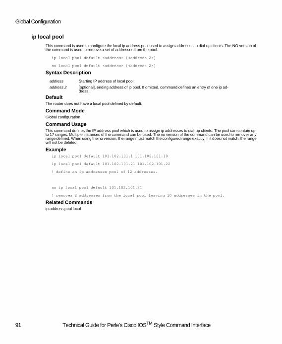
Global Configuration
ip local pool
This command is used to configure the local ip address pool used to assign addresses to dial-up clients. The NO version of the command is used to remove a set of addresses from the pool.
ip local pool default <address> [<address 2>]
no local pool default <address> [<address 2>]
Syntax Description
DefaultThe router does not have a local pool defined by default.
Command ModeGlobal configuration
Command UsageThis command defines the IP address pool which is used to assign ip addresses to dial-up clients. The pool can contain up to 17 ranges. Multiple instances of the command can be used. The no version of the command can be used to remover any range defined. When using the no version, the range must match the configured range exactly. If it does not match, the range will not be deleted.
Exampleip local pool default 101.102.101.1 101.102.101.10
ip local pool default 101.102.101.21 101.102.101.22
! define an ip addresses pool of 12 addresses.
no ip local pool default 101.102.101.21
! removes 2 addresses from the local pool leaving 10 addresses in the pool.
Related Commandsip address pool local
address Starting IP address of local pool
address 2 [optional], ending address of ip pool. If omitted, command defines an entry of one ip ad-dress.
91 Technical Guide for Perle’s Cisco IOSTM Style Command Interface

Supported Command Set Definitions
ip name-server
This command is used to define a DNS server. DNS servers are used to convert names to an ip address.
ip name-server <address> [<address 2>]
no name-server <address>
Syntax Description
DefaultNo DNS servers are defined by default.
Command ModeGlobal configuration
Command UsageThis command is used to configure the ip address of a primary and optionally a secondary DNS server. The router supplies these values to dial-up clients at connect time. The clients will use the DNS information whenever they need to convert a name to an address. (e.g. a browser may need to convert the web page address entered to its equivalent ip address).
Exampleip name-server 101.101.102.10
! defines the ip address of the DNS server to be 101.101.102.10
no ip name-server 101.101.102.10
! removes the DNS server configuration.
no ip name-server
! removes ALL DNS servers configured.
address IP address of DNS server
address 2 IP address of a secondary DNS server
92 Technical Guide for Perle’s Cisco IOSTM Style Command Interface

Global Configuration
ip route
This command is used to add an entry in the router's ip static route table.
ip route <address> <mask> {<address 2> | _user<user name>}
no ip route <address> <mask>
Syntax Description
DefaultNo routes are defined by default.
Command ModeGlobal configuration
Command UsageThis command is used to add a static route to the routing table. The gateway used to reach the destination can be specified as an ip address or a user name. If a user name is specified, the user must be defined on the router as a "lan to lan" user. A "lan to lan" user is used to define a dial-up client which is a router. If dynamic routing is enabled, before configuring a static route, enter the command "no router rip". This will suspend the processing of dynamic routes while the static routes are being updated. To resume dynamic routing, enter the command "routing rip" and specify the network to enable routing on by using the command "network n.n.n.n".
Exampleip route 1.1.0.0 255.255.0.0 101.101.102.2
! defines a route to network 1.1 via router 101.101.102.2
ip route 2.2.2.2 255.255.255.255 router1
! define a route to host 2.2.2.2 via a lan to lan user called router1.
no ip route 1.1.0.0 255.255.0.0
! removes the route to network 1.1
address Network number of destination ip address
mask Subnet mask of destination ip address
address 2 IP address of the next hop
user name The name of a "lan to lan" user defined on the router which will be the next hop.
93 Technical Guide for Perle’s Cisco IOSTM Style Command Interface

Supported Command Set Definitions
ip _win-name-server
This command is used to define a WINS server (Windows Internet Naming Service). WINS servers are used by Microsoft clients running the NetBIOS protocol.
ip _win-name-server <address> [<address 2>]
no _win-name-server <address>
Syntax Description
DefaultNo WINS servers are defined by default.
Command ModeGlobal configuration
Command UsageThis command is used to configure the ip address of a primary and optionally a secondary WINS server. The router supplies these values to dial-up clients at connect time. Dial-up Windows clients who are running the NetBIOS protocol make use of the services of a WINS server.
Exampleip _win-name-server 101.101.102.10
! defines the ip address of the WINS server to be 101.101.102.10
no ip _win-name-server 101.101.102.10
! removes the WINS server configuration.
no ip _win-name-server
! removes ALL WINS servers configured.
address IP address of WINS server
address 2 IP address of a secondary WINS server
94 Technical Guide for Perle’s Cisco IOSTM Style Command Interface

Global Configuration
ip _dhcp-lease
This command is used to set the duration of a DHCP lease. Use the "default" version of the command to restore the lease to its default value.
ip _dhcp-lease <time>
default ip _dhcp-lease
Syntax Description
DefaultThe default lease duration is 20 minutes.
Command ModeGlobal configuration
Command UsageThis command defines the lease time in minutes for an ip address obtained from a DHCP server. The lease time is automat-ically renewed by the router indefinitely as long as the dial-up connection is maintained. Upon the normal termination of a dial-up connection, the ip address is immediately released back to the DHCP server. In the event of an abnormal termination, the address is held for the dial-up user for a period of time specified by this command. (see "ip _dhcp-reconnect-disable" command). If the user re-connects before the expiration of this time, he will be assigned the same ip address.
The valid range for the lease time is 1 - 65535 minutes.
Exampleip _dhcp-lease 10
! upon an abnormal termination of a dial up client, the ip address assigned to that
!client by a DHCP server will released
no _dhcp-reconnect-disable
!upon an abnormal termination of a dial up client, the ip address to that
!client by a DHCP server will be reserved for this dial-up client for the
!duration of the lease.
Related Commandsip dhcp-server
ip _dhcp-reconnect-disable
time The lease time in minutes
95 Technical Guide for Perle’s Cisco IOSTM Style Command Interface
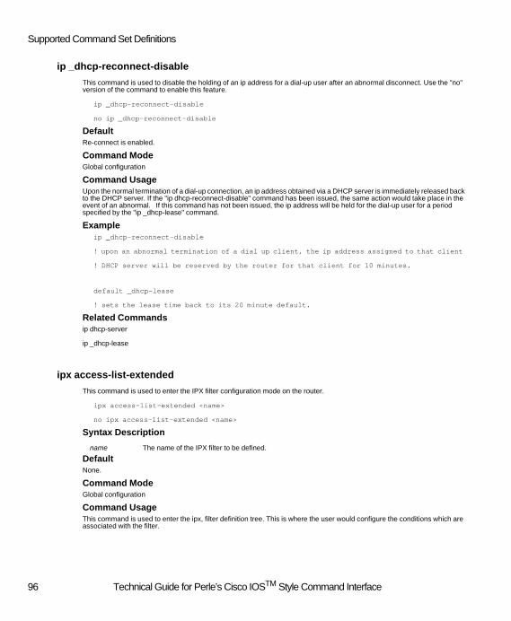
Supported Command Set Definitions
ip _dhcp-reconnect-disable
This command is used to disable the holding of an ip address for a dial-up user after an abnormal disconnect. Use the "no" version of the command to enable this feature.
ip _dhcp-reconnect-disable
no ip _dhcp-reconnect-disable
DefaultRe-connect is enabled.
Command ModeGlobal configuration
Command UsageUpon the normal termination of a dial-up connection, an ip address obtained via a DHCP server is immediately released back to the DHCP server. If the "ip dhcp-reconnect-disable" command has been issued, the same action would take place in the event of an abnormal. If this command has not been issued, the ip address will be held for the dial-up user for a period specified by the "ip _dhcp-lease" command.
Exampleip _dhcp-reconnect-disable
! upon an abnormal termination of a dial up client, the ip address assigned to that client
! DHCP server will be reserved by the router for that client for 10 minutes.
default _dhcp-lease
! sets the lease time back to its 20 minute default.
Related Commandsip dhcp-server
ip _dhcp-lease
ipx access-list-extended
This command is used to enter the IPX filter configuration mode on the router.
ipx access-list-extended <name>
no ipx access-list-extended <name>
Syntax Description
DefaultNone.
Command ModeGlobal configuration
Command UsageThis command is used to enter the ipx, filter definition tree. This is where the user would configure the conditions which are associated with the filter.
name The name of the IPX filter to be defined.
96 Technical Guide for Perle’s Cisco IOSTM Style Command Interface
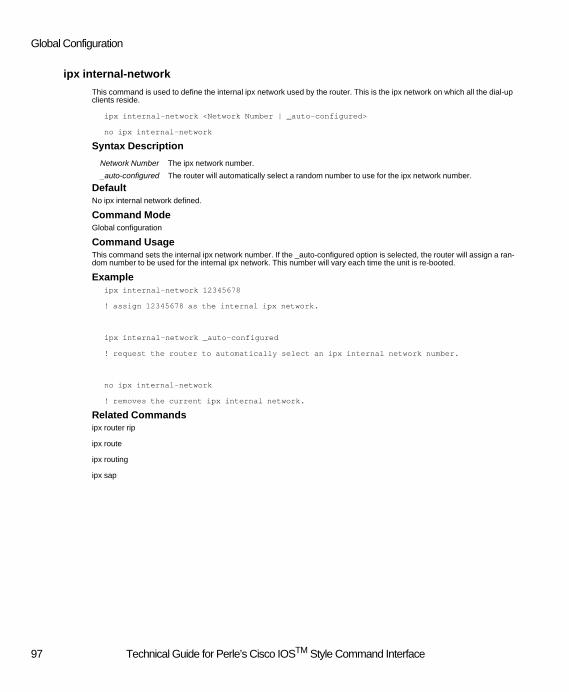
Global Configuration
ipx internal-network
This command is used to define the internal ipx network used by the router. This is the ipx network on which all the dial-up clients reside.
ipx internal-network <Network Number | _auto-configured>
no ipx internal-network
Syntax Description
DefaultNo ipx internal network defined.
Command ModeGlobal configuration
Command UsageThis command sets the internal ipx network number. If the _auto-configured option is selected, the router will assign a ran-dom number to be used for the internal ipx network. This number will vary each time the unit is re-booted.
Exampleipx internal-network 12345678
! assign 12345678 as the internal ipx network.
ipx internal-network _auto-configured
! request the router to automatically select an ipx internal network number.
no ipx internal-network
! removes the current ipx internal network.
Related Commandsipx router rip
ipx route
ipx routing
ipx sap
Network Number The ipx network number.
_auto-configured The router will automatically select a random number to use for the ipx network number.
97 Technical Guide for Perle’s Cisco IOSTM Style Command Interface

Supported Command Set Definitions
ipx route
This command is used to add an entry in the router's ipx static route table.
ipx route <destination network> {<router> | _user<user name>}
no ipx route <destination network>
Syntax Description
DefaultNo routes are defined by default.
Command ModeGlobal configuration
Command UsageThis command is used to add an ipx static route to the routing table. The gateway used to reach the destination can be spec-ified as an ipx address or a user name. If a user name is specified, the user must be defined on the router as a "lan to lan" user. A "lan to lan" user is used to define a dial-up client which is a router.
The next hop (router parameter above) must be one of the IPX networks configured for the router. (see “ipx network” com-mand).
Exampleipx route 12345678 87654321:1234.5678.9012
! defines a route to ipx network 12345678 via router 123456789012 on ipx network 87654321
no ipx route 12345678
! removes the route to ipx network 12345678
Related Commandsipx internal-network
ipx router rip
ipx routing
ipx sap
Destination network The destination ipx network number.
Router The ipx network and host address of the next hop.
User name The name of a "lan to lan" user defined on the router to be used as the next hop.
98 Technical Guide for Perle’s Cisco IOSTM Style Command Interface

Global Configuration
ipx router rip
This command is used to enable ipx rips on the server.
ipx router rip
no ipx router rip
DefaultThe sending of ipx rips is enabled.
Command ModeGlobal configuration
Command UsageThis command is used to enable the sending of ipx rips on the router. Rips will be sent on all ipx frame type enabled.
Related Commandsipx internal-network
ipx route
ipx routing
ipx sap
ipx routing
This command is used to enable ipx routing on the server.
ipx routing
no ipx routing
DefaultIPX routing is disabled.
Command ModeGlobal configuration
Command UsageThis command is used to enable ipx routing on the router.
Related Commandsipx internal-network
ipx route
ipx router rip
ipx sap
ipx network
99 Technical Guide for Perle’s Cisco IOSTM Style Command Interface

Supported Command Set Definitions
ipx sap
This command is used to add an entry in the router's SAP (Service Access Point) table.
ipx sap <server type> <server name> <ipx address> <socket #>
no ipx sap <server type> <server name>
Syntax Description
DefaultNo routes are defined by default.
Command ModeGlobal configuration
Command UsageThis command is used to add an ipx static Service Access Point. Once configured, this SAP can than be accessed by all users on the router.
The “ipx address” specified in the command must have been defined previously in an “ipx route” command. If this is not done, the command will be rejected.
Exampleipx sap 1234 spooler 87654321:1234.5678.9012 1111
! defines a SAP 1234 on server spooler with the address of 123456789012
!on ipx network 87654321 and a socket number of 1111.
no ipx sap 1234 spooler
! removes the SAP for server spooler
Related Commandsipx internal-network
ipx router rip
ipx route
ipx routing
server type The type of IPX service.
server name The name of the IPX server.
ipx address The ipx network and host address of the server.
socket The socket number of the service (4 digits).
100 Technical Guide for Perle’s Cisco IOSTM Style Command Interface
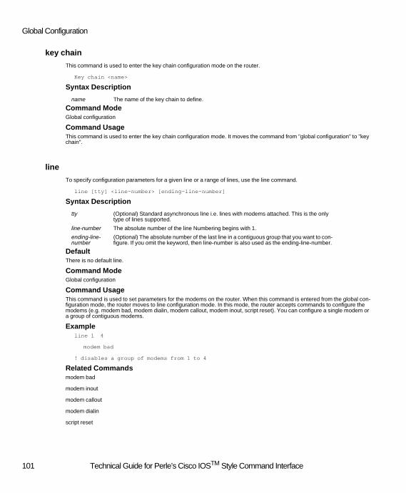
Global Configuration
key chain
This command is used to enter the key chain configuration mode on the router.
Key chain <name>
Syntax Description
Command ModeGlobal configuration
Command UsageThis command is used to enter the key chain configuration mode. It moves the command from "global configuration" to "key chain".
line
To specify configuration parameters for a given line or a range of lines, use the line command.
line [tty] <line-number> [ending-line-number]
Syntax Description
DefaultThere is no default line.
Command ModeGlobal configuration
Command UsageThis command is used to set parameters for the modems on the router. When this command is entered from the global con-figuration mode, the router moves to line configuration mode. In this mode, the router accepts commands to configure the modems (e.g. modem bad, modem dialin, modem callout, modem inout, script reset). You can configure a single modem or a group of contiguous modems.
Exampleline 1 4
modem bad
! disables a group of modems from 1 to 4
Related Commandsmodem bad
modem inout
modem callout
modem dialin
script reset
name The name of the key chain to define.
tty (Optional) Standard asynchronous line i.e. lines with modems attached. This is the only type of lines supported.
line-number The absolute number of the line Numbering begins with 1.
ending-line-number
(Optional) The absolute number of the last line in a contiguous group that you want to con-figure. If you omit the keyword, then line-number is also used as the ending-line-number.
101 Technical Guide for Perle’s Cisco IOSTM Style Command Interface

Supported Command Set Definitions
logging
This command is used to define the ip address of the syslog server to which all syslog entries will be sent.
logging <syslog server>
no logging <syslog server>
Syntax Description
DefaultNo syslog host defined.
Command ModeGlobal configuration
Command UsageThis command sets the ip address of the syslog server to which syslog entries will be sent. Up to 4 syslog servers can be defined. Each server will be defined using a separate "logging" command. A log event generated by the router will be sent to all syslog servers configured. The no version of the command can be used to remove a syslog server.
Examplelogging 101.101.102.100
logging 101.101.102.101
! defines 2 syslog servers
no logging 101.101.102.100
! removes one of the syslog servers configured above
Related Commandslogging trap
syslog server The ip address of the syslog server.
102 Technical Guide for Perle’s Cisco IOSTM Style Command Interface

Global Configuration
logging buffered
To log messages to an internal buffer, use the logging buffered command. Use the no or default form of this command to cancel the logging and return to the default settings.
logging buffered <log-type>
{no | default } logging buffered
Syntax Description
DefaultThe default is set to informational
Command ModeGlobal configuration
Command UsageThis command copies logging messages to an internal buffer. The buffer is circular in nature, so newer messages overwrite older messages after the buffer is filled.
To display the messages that are logged in the buffer, use the EXEC command show logging. The first message displayed is the most recent message in the buffer.
Examplelogging buffered
!enables logging to an internal buffer
Related Commandsshow logging
log-type This is the type of messages to log. The options are listed below:emergencies
alertscriticalerrors
warningsnotifications
information (default)debugging
103 Technical Guide for Perle’s Cisco IOSTM Style Command Interface
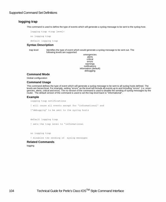
Supported Command Set Definitions
logging trap
This command is used to define the type of events which will generate a syslog message to be sent to the syslog host.
logging trap <trap level>
no logging trap
default logging trap
Syntax Description
Command ModeGlobal configuration
Command UsageThis command defines the type of event which will generate a syslog message to be sent to all syslog hosts defined. The levels are hierarchical. For example, setting "errors" as the level will include all events up to and including "errors" (i.e. emer-gencies, alerts, critical and error). The no version of the command is used to disable the sending of syslog messages by the router. The default version of the command is used to set the trap level back to "informational".
Examplelogging trap notifications
! will cause all events except for "informational" and
!"debugging" to be sent to the syslog hosts
default logging trap
! sets the trap level to "informational
no logging trap
! disables the sending of syslog messages
Related Commandslogging
trap level Identifies the type of event which would generate a syslog message to be sent out. The following levels are supported:
emergenciesalertscriticalerrors
warningsnotifications
information (default)debugging
104 Technical Guide for Perle’s Cisco IOSTM Style Command Interface

Global Configuration
_nt-domain-server allow-user-specified-domain
This command is used to configure the parameters associated with the Windows NT security server.
_nt-domain-server allow-user-specified-domain
no _nt-domain-server allow-user-specified-domain
DefaultUser override of domain name is not enabled.
Command ModeGlobal configuration
Command UsageThis command is used to configure enable/disable the users ability to specify a domain name. If this feature is enabled, the user can specify a domain name when logging in which will be appended to the user name to form the fully qualified user name. If this feature is disabled, the domain name configured on the router will be appended to the user name to form the fully qualified user name.
_nt-domain-server ip
This command is used to configure the parameters associated with the Windows NT security server using the ip protocol.
_nt-domain-server ip <domain> <address>
no _nt-domain-server ip
Syntax Description
Defaultnone
Command ModeGlobal configuration
Command UsageThis command is used to configure the parameters associated with the Windows NT security server. The domain name will be appended to the user name to fully qualify the user. The ip address of the NT server must be configured if it does not reside on the same ip network as the router. The PPP client must be able to support the use of PAP (Password Authentica-tion Protocol) in order to be authenticated using NT domain.
Example_nt-domain-server ip maindomain 101.101.33.2
! defines an NT domain security server using the ip protocol. The server
! is at ip address 101.101.33.2 with a default domain name
! of "maindomain"
no _nt-domain server ip
! removes the configuration for the NT domain security server for this router.
domain Default domain name (up to 16 characters)
address The IP address of the NT server
105 Technical Guide for Perle’s Cisco IOSTM Style Command Interface

Supported Command Set Definitions
_nt-domain-server ipx
This command is used to configure the parameters associated with the Windows NT security server using the ipx protocol.
_nt-domain-server ipx <domain>
no _nt-domain-server ipx
Syntax Description
Defaultnone
Command ModeGlobal configuration
Command UsageThis command is used to configure the parameters associated with the Windows NT security server. The domain name will be appended to the user name to fully qualify the user. The PPP client must be able to support the use of PAP (Password Authentication Protocol) in order to be authenticated using NT domain.
Example_nt-domain-server ipx maindomain
! defines an NT domain security server using the ipx protocol. A default domain name of
! "maindomain" will be used.
no _nt-domain server ipx
! removes the configuration for the NT domain security server for this router.
domain Default domain name (up to 16 characters)
106 Technical Guide for Perle’s Cisco IOSTM Style Command Interface

Global Configuration
radius-server deadtime
This command is used to configure the length of time to wait before attempting to communicate with a Radius host which did not respond to a previous request.
radius-server deadtime <time>
no radius-server deadtime
Syntax Description
Default0 minutes
Command ModeGlobal configuration
Command UsageThis command is used to configure the length of time the router will wait before attempting to communicate with a Radius host which failed to respond to a previous request. The deadtime value specified will apply to all four Radius hosts. A dead-time value of 0 indicates that the next time we need to authenticate a user, this host may be used.
Exampleradius-server deadtime 60
! defines a timeout of 60 minutes for all configured Radius host
radius-server host
This command is used to configure the Radius host ip address and UDP port information.
radius-server host <ip address> [auth-port <port#>] [acct-port <port#>]
radius-server {_auth-primary | _auth-backup} host <ip address> [auth-port <port#>]
radius-server {_acct-primary | _acct-backup} host <ip address> [acct-port <port#>]
no radius-server host <ip address>
no radius-server {_auth-primary | _auth-backup} host
no radius-server {_acct-primary | _acct-backup} host
Syntax Description
Defaultauth-port is defaulted to 1645
acct-port is defaulted to 1646
Command ModeGlobal configuration
Command UsageThis command is used to configure information about the Radius host being used to authenticate dial-in users. A Radius server can provide both authentication and accounting functions. The router can be configured to use the same Radius host
time In minutes (range 1-1440)
ip address The ip address of the radius host
port# The UDP port number used for authentication or accounting.
107 Technical Guide for Perle’s Cisco IOSTM Style Command Interface

Supported Command Set Definitions
for both functions or to have a separate Radius host for each function. In addition, the router can be configured with a backup server for each of these functions. To specifically configure the primary or backup authentication or accounting Radius hosts, use the appropriate _auth or _acct keyword. When using the "radius-server host" version, the first instance of the command would configure the primary authentication and accounting host. A second instance of this version of the command would configure the backup authentication and accounting Radius host.
Exampleradius-server host 101.101.102.16
! defines a Radius host at address 101.101.102.16 using an authentication UDP
!port of 1645 and an accounting UDP port of 1646
radius-server _acct-backup host 101.101.102.17 acct-port 1825
! configure a Radius accounting backup host at address 101.101.102.17
!using UDP port 1825
no radius-server host 101.101.102.16
! removes this radius host
radius-server key
This command is used to configure the name of the key which is shared with the Radius host.
radius-server key <key>
radius-server {_auth-primary | _auth-backup | _acct-primary | _acct-backup} key <key>
no radius-server key
no radius-server {_auth-primary | _auth-backup | _acct-primary | _acct-backup} key
Syntax Description
Defaultnone
Command ModeGlobal configuration
Command UsageThis command is used to configure the secret key which is shared with the Radius host. This must match the key configured on the Radius host for this router. Each Radius host can have a unique shared key. Use the _auth and _acct keywords to configure a specific Radius host's key information. If the "radius-server key" version of the command is used, it specifies a the shared secret for all Radius hosts.
Exampleradius-server key 1234567890
! defines a shared secret for all Radius hosts
key The secret key which is shared with the Radius host.
108 Technical Guide for Perle’s Cisco IOSTM Style Command Interface

Global Configuration
radius-server _acct-backup key 8254567
! configure a shared secret for the Radius accounting backup host
no radius-server _acct-backup key
! removes the shared secret for the accounting backup radius host
radius-server retransmit
This command is used to configure the number of times to re-try sending a request to a Radius host.
radius-server retransmit <count>
radius-server {_auth-primary | _auth-backup | _acct-primary | _acct-backup} retransmit <count>
no radius-server retransmit
Syntax Description
Default3 re-tries
Command ModeGlobal configuration
Command UsageThis command is used to configure the number of times the router will re-send a request to the Radius host. Each Radius host can have a unique value. Use the _auth and _acct keywords to configure a specific Radius host's re-try count. If the host is not specifically identified in the command, it will apply to all four Radius hosts.
Exampleradius-server retransmit 2
! defines a re-try count of 2 for all configured Radius host
radius-server _acct-backup retransmit 4
! configure a timeout value of 4 re-tries for the Radius accounting backup host
no radius-server _acct-backup retransmit
! disables re-transmission.
count Number of retries (range 1-100)
109 Technical Guide for Perle’s Cisco IOSTM Style Command Interface
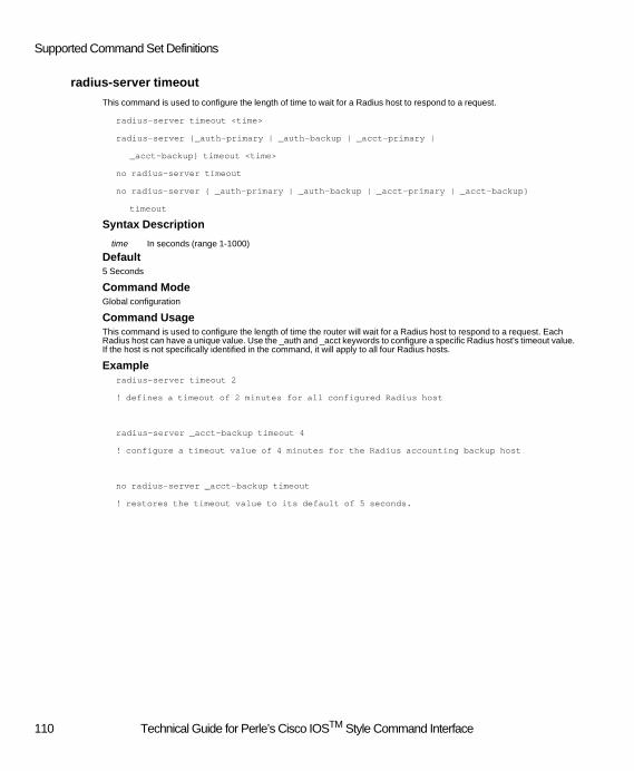
Supported Command Set Definitions
radius-server timeout
This command is used to configure the length of time to wait for a Radius host to respond to a request.
radius-server timeout <time>
radius-server {_auth-primary | _auth-backup | _acct-primary |
_acct-backup} timeout <time>
no radius-server timeout
no radius-server { _auth-primary | _auth-backup | _acct-primary | _acct-backup}
timeout
Syntax Description
Default5 Seconds
Command ModeGlobal configuration
Command UsageThis command is used to configure the length of time the router will wait for a Radius host to respond to a request. Each Radius host can have a unique value. Use the _auth and _acct keywords to configure a specific Radius host's timeout value. If the host is not specifically identified in the command, it will apply to all four Radius hosts.
Exampleradius-server timeout 2
! defines a timeout of 2 minutes for all configured Radius host
radius-server _acct-backup timeout 4
! configure a timeout value of 4 minutes for the Radius accounting backup host
no radius-server _acct-backup timeout
! restores the timeout value to its default of 5 seconds.
time In seconds (range 1-1000)
110 Technical Guide for Perle’s Cisco IOSTM Style Command Interface

Global Configuration
router rip
This command is used to enter the Router configuration mode on the router.
router rip
Command ModeGlobal configuration
Command UsageThis command is used to enter the global RIP configuration mode. It moves the command from "global configuration" to "router configuration".
Related Commandsnetwork
_securid-server client-server-protocol
This command is used to configure the parameters associated with the SecurID security server(s).
_securid-server client-server-protocol <version>
no _securid-server client-server-protocol
default _securid-server client-server-protocol
Syntax Description
DefaultV2.3.
Command ModeGlobal configuration
Command UsageThis command is used to configure the version of the protocol being used. This version should match the version being used on the SecurID host.
Example_securid-server client-server-protocol V2.2
! sets the type of version to 2.2
default _securid-server client-server-protocol
! sets the version to its default value of 2.3
version Identifies the version of Client/Server communication protocol being used. The valid op-tions are v2.3 and v2.2
111 Technical Guide for Perle’s Cisco IOSTM Style Command Interface

Supported Command Set Definitions
_securid-server encryption
This command is used to configure the parameters associated with the SecurID security server(s).
_securid-server encryption <encryption>
no _securid-server encryption
default _securid-server encryption
Syntax Description
DefaultSDI.
Command ModeGlobal configuration
Command UsageThis command is used to configure the type of encryption to be used when communicating with the SecurID security server. The encryption type configured using this command must match the setting on the SecurID host.
Example_securid-server encryption DES
! sets the type of encryption to be used to DES
default _securid-server encryption
! restores the encrytption type to its default value of SDI
_securid-server master-server
This command is used to configure the parameters associated with the master SecurID security server.
_securid-server master-server <address> <port>
no _securid-server master-server
Syntax Description
DefaultThe UDP port has a default of 5500.
Command ModeGlobal configuration
Command UsageThis command is used to configure the ip address and UDP port of the master Secure ID security server. A slave server can also be defined using the "_securid-server slave-server" command.
encryption The type of encryption to be used when communicating with the SecurID host. The sup-ported encryption types are DES or SDI.
address The ip address of the SecurID host.
port The UDP port used to communicate with the host.
112 Technical Guide for Perle’s Cisco IOSTM Style Command Interface

Global Configuration
Example_securid-server master-server 101.101.103.2 5230
! defines a master SecurID server at an ip address of 101.101.103.2 using a UDP port number
! of 5230
no _securid-server master-server
! removes the configuration for the master SecurID security server for this router.
_securid-server reset-node-secret
This command is used to configure the parameters associated with the SecurID security server(s).
_securid-server reset-node-secret
no _securid-server reset-node-secret
default _securid-server reset-node-secret
DefaultThe feature is disabled.
Command ModeGlobal configuration
Command UsageThis command is used to configure whether the secret shared between the SecurID host and the router is to be reset the first time the router sends an authentication request to the security server. The node secret is used in the encryption of the user password.
Example_securid-server reset-node-secret
! enables this feature.
default _securid-server reset-node-secret
! disable the feature.
113 Technical Guide for Perle’s Cisco IOSTM Style Command Interface

Supported Command Set Definitions
_securid-server slave-server
This command is used to configure the parameters associated with the slave SecurID security server.
_securid-server slave-server <address> <port>
no _securid-server slave-server
Syntax Description
DefaultThe UDP port has a default of 5500.
Command ModeGlobal configuration
Command UsageThis command is used to configure the ip address and UDP port of the slave Secure ID security server.
Example_securid-server slave-server 101.101.103.3
! defines a master SecurID server at an ip address of 101.101.103.3 using the
!default UDP port number of 5500
no _securid-server slave-server
! removes the configuration for the slave SecurID security server for this router.
address The ip address of the SecurID host.
port The UDP port used to communicate with the host.
114 Technical Guide for Perle’s Cisco IOSTM Style Command Interface

Global Configuration
service password-encryption
Use this command to encrypt user passwords.
service password-encryption
no service password-encryption
Syntax Description No parameters
DefaultNo password encryption.
Command ModeGlobal configuration
Command UsageThis command is used to encrypt user passwords in the running-config file. When the command is executed, service pass-word-encryption is turned ON and all user passwords in the running-config file are encrypted. This command is useful for preventing unauthorized individuals from viewing passwords in your configuration file.
When the no version of this command is executed, service password-encryption is turned OFF. Any user passwords current-ly encrypted in the running-config file are unaffected. You cannot use this command to decrypt passwords. New passwords entered after service password-encryption is turned OFF will be added to the running-config file in the clear.
Exampleservice password-encryption
!turns on service password-encryption and encrypts all username passwords currently
!in the running-config file.
no service password-encryption
!turns off service password-encryption. Username passwords in the running-config
!file are not affected.
115 Technical Guide for Perle’s Cisco IOSTM Style Command Interface

Supported Command Set Definitions
_shared-database-server
This command is used to configure the parameters associated with the SUL (Shared User List) server.
_shared-database-server <server> <address>
no _shared-database-server <server>
Syntax Description
Defaultnone
Command ModeGlobal configuration
Command UsageThis command is used to configure information on other routers from which this router could request user information. Spe-cific servers can be defined by this command. If this feature is enabled, if a user is being authenticated, the router will check its local data base for a record for this user. If no matching record can be found, the router will request the routers defined by this command for a matching record on this user. If one is found, the user can be authenticated and will be granted access to the router.
Example_shared-database-server 1 101.101.102.45
! defines a router at ip address 101.101.102.45 which can be used to supply user
!records for the router.
No _shared-database-server 1
! removes this router for the purpose of validating users.
server Server being defined1 = server 12 = server 2
address IP address or server name if IPX is being used.
116 Technical Guide for Perle’s Cisco IOSTM Style Command Interface
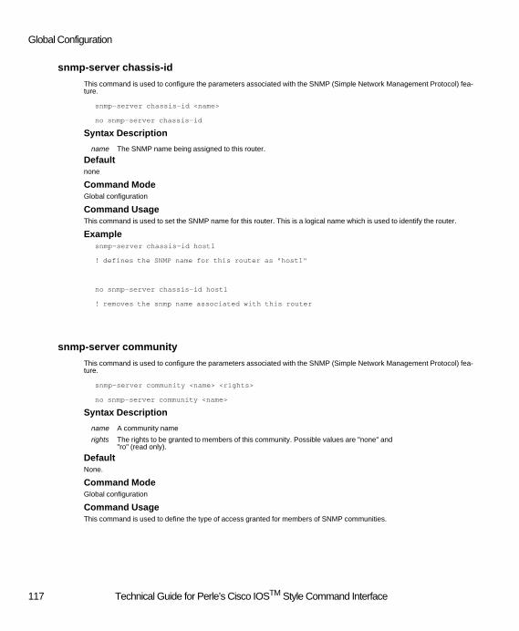
Global Configuration
snmp-server chassis-id
This command is used to configure the parameters associated with the SNMP (Simple Network Management Protocol) fea-ture.
snmp-server chassis-id <name>
no snmp-server chassis-id
Syntax Description
Defaultnone
Command ModeGlobal configuration
Command UsageThis command is used to set the SNMP name for this router. This is a logical name which is used to identify the router.
Examplesnmp-server chassis-id host1
! defines the SNMP name for this router as "host1"
no snmp-server chassis-id host1
! removes the snmp name associated with this router
snmp-server community
This command is used to configure the parameters associated with the SNMP (Simple Network Management Protocol) fea-ture.
snmp-server community <name> <rights>
no snmp-server community <name>
Syntax Description
DefaultNone.
Command ModeGlobal configuration
Command UsageThis command is used to define the type of access granted for members of SNMP communities.
name The SNMP name being assigned to this router.
name A community name
rights The rights to be granted to members of this community. Possible values are "none" and "ro" (read only).
117 Technical Guide for Perle’s Cisco IOSTM Style Command Interface

Supported Command Set Definitions
Examplesnmp-server community 833routers ro
! grants SNMP members who are part of the community called "833routers" read only access.
no snmp-server community 833routers
! removes the rights of the members of the SNMP community of "833routers"
snmp-server contact
This command is used to configure the parameters associated with the SNMP (Simple Network Management Protocol) fea-ture.
snmp-server contact <name>
no snmp-server contact
Syntax Description
Defaultnone
Command ModeGlobal configuration
Command UsageThis command is used to set the SNMP contact name for this router. This is a logical name which is used to provide informa-tion about who is responsible for managing this device.
Examplesnmp-server contact Dave Jones
! defines the SNMP contact name for this router as "Dave Jones"
no snmp-server contact
! removes the snmp contact name associated with this router
name The SNMP name of the person who is the contact for this site.
118 Technical Guide for Perle’s Cisco IOSTM Style Command Interface

Global Configuration
snmp-server host
This command is used to configure the parameters associated with the SNMP (Simple Network Management Protocol) fea-ture.
snmp-server host <address> traps <community>
no snmp-server host <address>
Syntax Description
Defaultnone
Command ModeGlobal configuration
Command UsageThis command is used to set the SNMP trap host information. When the router detects a serious condition or activity, it will send a message known as a "trap" to the host defined by this command.
Examplesnmp-server host 101.101.102.66 traps public
! defines the SNMP trap host who is part of the SNMP community
!"public" and is at the ip address of 101.101.102.66
no snmp-server host 101.101.102.66
! removes this SNMP trap host
address The ip address of the SNMP trap host.
community The community that the trap host belongs to.
119 Technical Guide for Perle’s Cisco IOSTM Style Command Interface
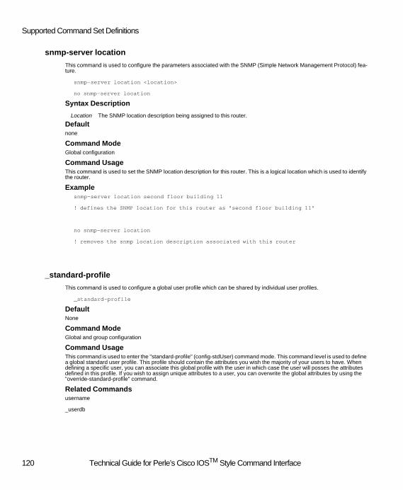
Supported Command Set Definitions
snmp-server location
This command is used to configure the parameters associated with the SNMP (Simple Network Management Protocol) fea-ture.
snmp-server location <location>
no snmp-server location
Syntax Description
Defaultnone
Command ModeGlobal configuration
Command UsageThis command is used to set the SNMP location description for this router. This is a logical location which is used to identify the router.
Examplesnmp-server location second floor building 11
! defines the SNMP location for this router as "second floor building 11"
no snmp-server location
! removes the snmp location description associated with this router
_standard-profile
This command is used to configure a global user profile which can be shared by individual user profiles.
_standard-profile
DefaultNone
Command ModeGlobal and group configuration
Command UsageThis command is used to enter the "standard-profile" (config-stdUser) command mode. This command level is used to define a global standard user profile. This profile should contain the attributes you wish the majority of your users to have. When defining a specific user, you can associate this global profile with the user in which case the user will posses the attributes defined in this profile. If you wish to assign unique attributes to a user, you can overwrite the global attributes by using the "override-standard-profile" command.
Related Commandsusername
_userdb
Location The SNMP location description being assigned to this router.
120 Technical Guide for Perle’s Cisco IOSTM Style Command Interface
Global Configuration
_userdb
This command is used to configure additional parameters for a user defined using the "username" command.
_userdb <name>
no _userdb <name>
Syntax Description
DefaultNone
Command ModeGlobal configuration
Command UsageThis command is used to enter the "userdb" command mode. This command level enables the user to configure additional parameters for a user who was configured using the "username" command. Attributes configured in the userdb tree will be appended to the attributes configured using the "username" command. No version of the command will delete any _userdb records associated with this user as well as the “username” record associated with this user.
Exampleuserdb joe
! switches the command mode to the "userdb" level. All subsequent commands entered
! at that level will apply to the user "joe"
no userdb joe
! deletes the user called "joe"
Related Commandsusername
_standard-profile
name The user name. Up to 32 characters can be used.
121 Technical Guide for Perle’s Cisco IOSTM Style Command Interface

Supported Command Set Definitions
username
This command is used to configure a user on the internal user data base of the router.
username <name> [callback-dialstring <phone number>]
[ callback-rotary <group> ] {password [<encryption type>]
<password> | nopassword}
no username <name>
Syntax Description
DefaultNone
Command ModeGlobal configuration
Command UsageThis command is used to configure a user into the internal user database. All dial-up clients need to be validated by the router. If the authentication type is set for "local", the internal user database will be used to authenticate dial-up users. If an external security server is used to authenticate dial-up clients, the internal user database will be checked after authentication is successfully completed by the external security server. If the user is found in the internal database the attributes configured locally will be appended to any attributes provided by the external security server. The "_userdb" command can be used to configure additional parameters for the user.
Exampleusername joe password boss
! defines a user called "joe" with a password of "boss"
no username joe
! deletes the user called "joe"
Related Commands_userdb
_standard-profile
name The user name. Must be unique. Up to 32 characters can be used.
phone number A phone number at which the user will be called back. A blank dialstring "" will cause a roaming callback to be performed.
group The name of a callback group which will be used to select a line to call the user back on. The group must have "callback" enabled.
encryption type The type of encryption algorithom to use. Valid types are 0 - 100 (100 is the proprietary encryption used by this router).
password The password associated with the user. Up to 32 characters can be used.
122 Technical Guide for Perle’s Cisco IOSTM Style Command Interface

Group Configuration
Group Configuration
callback
This command is used to configure a parameter associated with a group.
callback
no callback
DefaultEnabled for callback.
Command ModeGroup configuration
Command UsageThis command is used to configure the group callback capabilities. If callback is specified, the resources in the group can be used to satisfy callback requests.
Example_group engineers
callback
! Resources in the group called "engineers" can be used to satisfy callback requests.
_group engineers
no callback
! Resources in the group called "engineers" will not be used to satisfy callback requests.
123 Technical Guide for Perle’s Cisco IOSTM Style Command Interface

Supported Command Set Definitions
channels
This command is used to configure a parameter associated with a group.
channels <name>
no channels <name>
Syntax Description
Command ModeGroup configuration
Command UsageThis command is used to configure the channels associated with a group. The user can select which BRI channels they wish to have included in this group. Once assigned to the group, the channels will take on the common attributes of the group. A channel can only belong to one group. Multiple channel names can appear on the command line. When removing a channel from the group you must use the no version of the command. You can specify one or more channels to be removed on the command line.
Example_group engineers
channels line1 line2 line3
! Assigned channels "line1", "line2" and "line3" to the group called "engineers".
_group engineers
no channels line1 line2
! Removes "line1" and "line2" from the group called "engineers".
name The name of a BRI channel to be assigned to the group.
124 Technical Guide for Perle’s Cisco IOSTM Style Command Interface
Group Configuration
dialin
This command is used to configure a parameter associated with a group.
dialin
no dialin
DefaultEnabled for dial-in.
Command ModeGroup configuration
Command UsageThis command is used to configure the group dial-in capabilities. If dialin is specified, the resources in the group can be used to accept dial-in calls.
Example_group engineers
dialin
! Resources in the group called "engineers" can be used to accept dial-in calls.
_group engineers
no dialin
! Resources in the group called "engineers" will not be used accept dial-in calls.
dialout
This command is used to configure a parameter associated with a group.
dialout
no dialout
DefaultEnabled for dial-out.
Command ModeGroup configuration
Command UsageThis command is used to configure the group dial-out capabilities. If dialout is specified, the resources in the group can be used to satisfy dial-out requests. Please note that enabling this capability does reserve some system resources so that if you are not going to make use of the dialout feature, do not include this capability for the group.
Example_group engineers
dialout
! Resources in the group called "engineers" can be used to satisfy dial-out requests.
125 Technical Guide for Perle’s Cisco IOSTM Style Command Interface
Supported Command Set Definitions
_group engineers
no dialout
! Resources in the group called "engineers" will not be used to satisfy dial-out requests.
modems
This command is used to configure a parameter associated with a group.
modems <name>
no modems <name>
Syntax Description
Command ModeGroup configuration
Command UsageThis command is used to configure the modems associated with a group. The user can select which modem(s) they wish to have included in this group. Once assigned to the group, the modems will take on the common attributes of the group. A modem can be assigned to more than one group. Multiple modem names can appear on the command line. When removing a modem from the group you must use the no version of the command. You can specify one or more modems to be removed on the command line.
Example_group engineers
modems modem1 modem2 modem3
! Assigned modems "modem1", "modem2" and "modem3" to the group called "engineers".
_group engineers
no modems modem1 modem2
! Removes "modem1" and "modem2" from the group called "engineers".
Related Commandsmodems _name
_name1
_name2
name The name of a modem to be assigned to the group.
126 Technical Guide for Perle’s Cisco IOSTM Style Command Interface

Group Configuration
ppp timeout retry
This command is used to configure the PPP retry timeout value.
ppp timeout retry <time>
default ppp timeout retry
Syntax Description
Default3 seconds.
Command ModeInterface and group configuration.
Command UsageThis command is used to configure the re-try time value for PPP. PPP will wait this long for a response to a PPP negotiation message before re-transmitting the request. The default version of the command is used to return the value to its default of 3 seconds.
Exampleinterface dialer 0
ppp timeout retry 5
! Sets the PPP re-try value to 5 seconds.
interface dialer 0
default ppp timeout retry
! Sets the PPP re-try value to 3 seconds.
time Re-try time in seconds.
127 Technical Guide for Perle’s Cisco IOSTM Style Command Interface

Supported Command Set Definitions
Interface (ISDN, Ethernet,Token Ring)
_arap enable
This command is used to enable the ARAP (Apple Remote Access Protocol) stack.
_arap enable
no _arap enable
DefaultProtocol is disabled.
Command ModeInterface configuration
Command UsageThis command is used to enable the ARAP protocol. This protocol is used by some Apple dial-up clients. This command can show up under multiple interfaces (e.g. group_async and dialer), the dialer interface is the one which actually determines the mode of operation for dial-up users.
Example_arap enable
! enables Apple dial-up clients to use the ARAP protocol
no _arap enable
! disables the ARAP protocol for dial-up clients.
async dynamic address
This command is used to allow dial-up clients to specify the ip address they wish to use.
aysnc dynamic address
no aysnc dynamic address
DefaultDynamic addressing is disabled.
Command ModeInterface configuration
Command UsageThis command specifies whether the dial-up ip client is allowed to specify the ip address they want to use. If this command is not specified, the dial-up client must obtain its ip address from the router. The router may obtain the ip address from a number of sources including the internal user database, the internal global ip pool, a dhcp server or an external security server.
Related Commandsip dhcp-server
ip local-pool
ip address-pool
128 Technical Guide for Perle’s Cisco IOSTM Style Command Interface
Interface (ISDN, Ethernet,Token Ring)
_bcp enable
This command is used to enable the BCP (Bridge Control Protocol) stack.
_bcp enable
no _bcp enable
DefaultProtocol is disabled.
Command ModeInterface configuration
Command UsageThis command is used to enable the BCP protocol. This protocol is used by some dial-up clients. This command can show up under multiple interfaces (e.g. group_async and dialer), the dialer interface is the one which actually determines the mode of operation for dial-up PPP users.
Example_bcp enable
! enables dial-up clients to use the BCP protocol
no _bcp enable
! disables the BCP protocol for dial-up clients.
Related Commands_bcp mac-address-client-specified
_bcp filter multicast
_bcp filter broadcast
_bcp-netbeui local-pool
129 Technical Guide for Perle’s Cisco IOSTM Style Command Interface

Supported Command Set Definitions
_bcp filter broadcast
This command is used to enable/disable the forwarding of broadcast packets when using the BCP (Bridge Control Protocol) stack.
_bcp filter broadcast
no _bcp filter broadcast
DefaultBroadcasts are not forwarded.
Command ModeInterface and Group configuration
Command UsageThis command is used to enable/disable the forwarding of broadcast packets from the lan to the wan. To enable the forward-ing of broadcasts, use the no version of the command.
Example_bcp filter broadcast
! prevents broadcast packets from being forwarded from the lan to the dial-up client.
no _bcp filter broadcast
! broadcasts will be forwarded from the lan to the dial up client.
Related Commands_bcp mac-address-client-specified
_bcp enable
_bcp-netbeui local-pool
_bcp filter multicast
130 Technical Guide for Perle’s Cisco IOSTM Style Command Interface

Interface (ISDN, Ethernet,Token Ring)
_bcp filter multicast
This command is used to enable/disable the forwarding of multicast packets when using the BCP (Bridge Control Protocol) stack.
_bcp filter multicast
no _bcp filter multicast
DefaultMulticasts are not forwarded.
Command ModeInterface and Group configuration
Command UsageThis command is used to enable/disable the forwarding of multicast packets from the lan to the wan. To enable the forward-ing of Multicast packets, use the no version of the command.
Example_bcp filter multicast
! prevents multicast packets from being forwarded from the lan to the dial-up client.
no _bcp filter multicast
! multicasts will be forwarded from the lan to the dial up client.
Related Commands_bcp mac-address-client-specified
_bcp enable
_bcp-netbeui local-pool
_bcp filter broadcast
131 Technical Guide for Perle’s Cisco IOSTM Style Command Interface

Supported Command Set Definitions
_bcp mac-address-client-specified
This command is used to enable the BCP client to provide the MAC address it wishes to use.
_bcp mac-address-client-specified
no _bcp mac-address-client-specified
DefaultFeature is disabled.
Command ModeInterface configuration
Command UsageThis command is used to enable the ability of the dial-up, BCP client to specify the MAC address it wishes to be assigned to it. If this feature is disabled (default), the client will be assigned a MAC address from the global pool. This command can show up under multiple interfaces (e.g. group_async and dialer), the dialer interface is the one which actually determines the mode of operation for dial-up PPP users.
Example_bcp mac-address-client-specified
! enables dial-up clients to specify the MAC address
!they would like to use
no _bcp mac-address-client-specified
! MAC addresses for BCP clients will be supplied
! from the router's pool
Related Commands_bcp enable
_bcp-netbeui local-pool
132 Technical Guide for Perle’s Cisco IOSTM Style Command Interface

Interface (ISDN, Ethernet,Token Ring)
_bcp-netbeui local-pool
This command is used to configure the local MAC address pool on the router.
_bcp-netbeui local-pool <mac-address>
no _bcp-netbeui local-pool
Syntax Description
DefaultNo pool defined.
Command ModeInterface configuration
Command UsageThis command is used to define the global MAC address pool for the router. When a BCP or NetBeui (NetBIOS) client dials into the router, he will get a MAC address assigned to him. This address will come from this pool. Addresses assigned to concurrent dial-up clients will always be unique. The number of address in the pool will equal the maximum number of simul-taneous dial-up clients the router can support.
The last two digits of the MAC Address must be 00.
Example_bcp-netbeui local-pool 1111.2222.3300
! specifies the starting address of the MAC pool at 111122223300
no _bcp-netbeui local-pool
! removes the local MAC address pool
Related CommandsNetbios nbf
_bcp enable
Mac-address The base address for the local MAC address pool. Format of MAC address is h.h.h where h = 4 digit, hexadecimal number.
133 Technical Guide for Perle’s Cisco IOSTM Style Command Interface

Supported Command Set Definitions
compress stac
This command is used to enable the use of STAC compression.
compress stac
no compress stac
DefaultNo STAC compression.
Command ModeInterface and group configuration.
Command UsageThis command is used to enable/disable the use of STAC compression. STAC compression can be used to compress the data portion of a packet on a dial-up link. If you are using an analog connection, the modem is already performing compres-sion on the data and there is no benefit in performing STAC compression. In the case of a digital connection, there can be a benefit. How much of a benefit you will achieve depends on how compressible the data you are sending is.
When this command is used within the "interface" configuration mode, the interface determines the type of compression des-ried (i.e. analog or digital). When this command is used within the "group" configuration this information is not available. The user must therefore change the command slightly when it is used in that mode. The command is as follows;
compress _stac-digital - defines that digital calls should be compressed.
compress _stac-analog - defines that analog calls should be compressed.
Exampleinterface dialer 0
compress stac
! Turns on stac compression for this interface.
134 Technical Guide for Perle’s Cisco IOSTM Style Command Interface

Interface (ISDN, Ethernet,Token Ring)
dialer callback-server
To enable an interface to make return calls when callback is successfully negotiated, use the dialer callback-server com-mand. Use the no form of this command to disable callback.
dialer callback-server
no dialer callback-server
Syntax Description No parameters.
Default Callback is disabled on the interface.
Command ModeInterface configuration
Command UsageThis command is used to allow callback on all channels on the specified interface. This command must be used for Call Back Control Protocol (CBCP) negotiated callbacks to occur on an interface. When the callback configuration is changed for an active interface, any incoming or outgoing calls on the interface will be dropped.
Exampleinterface BRI0
dialer callback-server
!configures both channels on BRI 0 to allow callbacks to occur.
dialer _dialin disabled
To disable both B channels on an ISDN BRI interface for dialin access use the dialer _dialin disabled command. Use the no or default form of this command to enable both channels for dial in access.
dialer _dialin disabled
{ no | default } dialer _dialin disabled
Syntax Description No parameters
DefaultBoth channels are enabled for dialin access
Command ModeInterface configuration
Command UsageWhen the dial-in configuration is changed for an active interface, any incoming or outgoing calls on the interface will be dropped.
Exampleinterface BRI 0
dialer _dialin-server disabled
!disables dialin access on both B channels for the first ISDN interface.
135 Technical Guide for Perle’s Cisco IOSTM Style Command Interface

Supported Command Set Definitions
dialer _dialout enabled
To enable both B channels on an ISDN BRI interface for dial out access use the dialer _dialout enabled command. Use the no or default form of this command to disable both channels for dial out access.
dialer _dialout enabled
{ no | default } dialer _dialout enabled
Syntax Description No parameters
DefaultBoth channels are disabled for dialout access
Command ModeInterface configuration
Command UsageThis command is used to allow workstations on the LAN to use modems on the router for dialout access (i.e. sending faxes, access the Internet or Bulletin Board Service (BBS)). When the dialout configuration is changed for an active interface, any incoming or outgoing calls on the interface will be dropped.
Exampleinterface BRI 0
dialer _dialout enabled
!enables both B channels on the ISDN interface for dialout access.
136 Technical Guide for Perle’s Cisco IOSTM Style Command Interface

Interface (ISDN, Ethernet,Token Ring)
dialer rotary-group
To include a specified interface in a dialer rotary group, use the dialer rotary-group command. To remove the specified inter-face from the dialer rotary group, use the no form of this command.
dialer rotary-group <number>
no dialer rotary-group <number>
Syntax Description
DefaultNo interfaces are included in a dialer rotary group.
Command ModeInterface configuration
Command UsageThis command is used to associate a Dialer with BRI interfaces. The protocol definitions in the dialer interface are inherited by all the BRI interfaces in the rotary-group (e.g. if the command “ppp authentication pap" is defined in the dialer interface then it will be used by all BRI interfaces in the rotary-group).
Exampleinterface dialer 0
encapsulation ppp
ppp authentication chap
interface bri 0
dialer rotary-group 0
interface bri 1
dialer rotary-group 0
! places BRI interfaces 0 and 1 into dialer rotary group 0, defined by the
!interface dialer 0 command. The ppp authentication will be chap
!for both BRI interfaces.
number Number of the previously defined dialer interface in whose rotary group this BRI interface is to be included. This is a number from 0 to 255. The dialer interface is defined by the interface dialer command. Currently only 0 is used.
137 Technical Guide for Perle’s Cisco IOSTM Style Command Interface
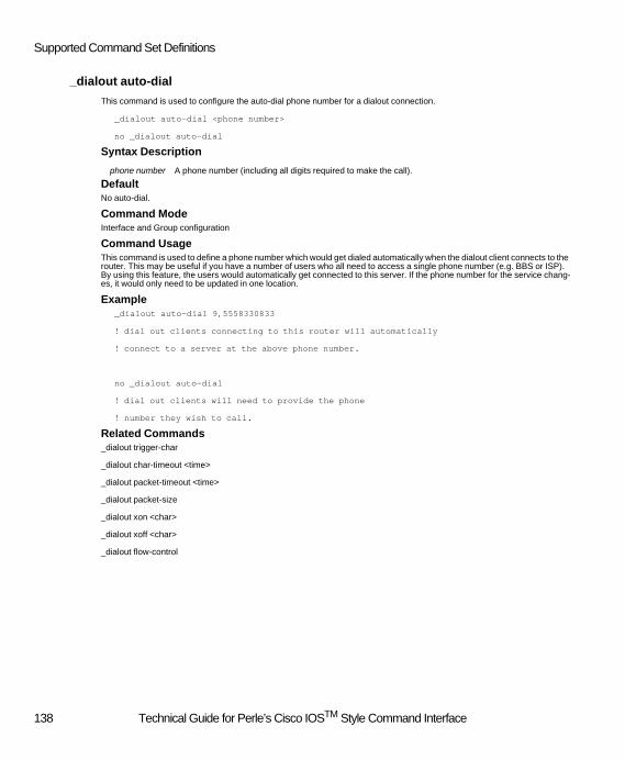
Supported Command Set Definitions
_dialout auto-dial
This command is used to configure the auto-dial phone number for a dialout connection.
_dialout auto-dial <phone number>
no _dialout auto-dial
Syntax Description
DefaultNo auto-dial.
Command ModeInterface and Group configuration
Command UsageThis command is used to define a phone number which would get dialed automatically when the dialout client connects to the router. This may be useful if you have a number of users who all need to access a single phone number (e.g. BBS or ISP). By using this feature, the users would automatically get connected to this server. If the phone number for the service chang-es, it would only need to be updated in one location.
Example_dialout auto-dial 9,5558330833
! dial out clients connecting to this router will automatically
! connect to a server at the above phone number.
no _dialout auto-dial
! dial out clients will need to provide the phone
! number they wish to call.
Related Commands_dialout trigger-char
_dialout char-timeout <time>
_dialout packet-timeout <time>
_dialout packet-size
_dialout xon <char>
_dialout xoff <char>
_dialout flow-control
phone number A phone number (including all digits required to make the call).
138 Technical Guide for Perle’s Cisco IOSTM Style Command Interface

Interface (ISDN, Ethernet,Token Ring)
_dialout char-timeout
This command is used to configure the inter-character which is used to determine when to forward data collected from the modem on to the lan.
_dialout char-timeout <time>
no _dialout char-timeout
Syntax Description
Defaultchar-timeout = 60 ms.
Command ModeInterface and Group configuration
Command UsageThis command is used to configure the inter-character timeout. The inter-character timeout is the maximum amount of time that the router will wait for the next character to arrive. If the time between the characters exceeds the configured "char-timeout" value, all the characters that have been received up until that point will be forwarded on the lan. Valid timeouts are 0 - 65535 ms.
Example_dialout char-timeout 100
! sets the inter-character timeout to 100
no _dialout char-timeout
! sets the inter-character timeout back to default values of 60 ms.
Related Commands_dialout trigger-char
_dialout packet-size
_dialout packet-timeout
_dialout flow-control
_dialout xon <char>
_dialout xoff <char>
_dialout auto-dial
time Timeout value in milliseconds. Valid timeouts are 0 - 65535 ms.
139 Technical Guide for Perle’s Cisco IOSTM Style Command Interface

Supported Command Set Definitions
_dialout flow-control
This command is used to configure the flow control characters used by the dial out application.
_dialout flow-control { hardware | xon-xoff }
no _dialout flow-control
DefaultHardware flow control.
Command ModeInterface and Group configuration
Command UsageThis command is used to configure the method of flow control which will be used between the router and the modem. This method needs to match the method identified in the "init" string sent to the modem. The default "init string" used in the router sets the flow control to hardware.
Example_dialout flow-control hardware
! sets the flow control method to hardware.
no _dialout flow-control
! sets the flow control method to no flow control.
Related Commands_dialout trigger-char
_dialout char-timeout <time>
_dialout packet-timeout <time>
_dialout packet-size
_dialout xon <char>
_dialout xoff <char>
_dialout auto-dial
140 Technical Guide for Perle’s Cisco IOSTM Style Command Interface

Interface (ISDN, Ethernet,Token Ring)
_dialout packet-size
This command is used to configure the maximum size of data collected from the modem before it is forwarded on the lan.
_dialout packet-size <bytes>
no _dialout packet-size
Syntax Description
DefaultPacket size = 140
Command ModeInterface and Group configuration
Command UsageThis command is used to configure the maximum number of bytes which will be collected from the modem before being placed in a packet to be forwarded on the lan. This defines a maximum value only. Based on other configurable parameters for dialout, a smaller packet can be sent on the lan.
Example_dialout packet-size 100
! if 80 bytes are received from the modem, they will be
!sent on the lan to the dialout client.
no _dialout packet-size
! sets the packet size back to 140 (default)
Related Commands_dialout trigger-char
_dialout char-timeout <time>
_dialout packet-timeout <time>
_dialout flow-control
_dialout xon <char>
_dialout xoff <char>
_dialout auto-dial
bytes Maximum data size.
141 Technical Guide for Perle’s Cisco IOSTM Style Command Interface

Supported Command Set Definitions
_dialout packet-timeout
This command is used to configure the inter-packet timeouts which is used to determine when to forward data collected from the modem on to the lan.
_dialout packet-timeout <time>
no _dialout packet-timeout
Syntax Description
Defaultpacket-timeout = 720 ms.
Command ModeInterface and Group configuration
Command UsageThis command is used to configure the inter-packet timeout value. The inter-packet timeout is the maximum amount of time that the router will wait from the time it starts to collect a packet to the time it will forward the packet. When this time elapses, the packet will be forwarded on the lan. Valid timeouts are 0 - 65535 ms.
Example_dialout packet-timeout 1000
! sets the inter-packet timeout to 1000 ms (1 second).
no _dialout packet-timeout
! sets the inter-packet timeout back to default value of 720 ms
Related Commands_dialout trigger-char
_dialout packet-size
_dialout char-timeout
_dialout flow-control
_dialout xon <char>
_dialout xoff <char>
_dialout auto-dial
time Timeout value in milliseconds. Valid timeouts are 0 - 65535 ms
142 Technical Guide for Perle’s Cisco IOSTM Style Command Interface

Interface (ISDN, Ethernet,Token Ring)
_dialout trigger-char
This command is used to configure the characters which will cause a packet to be forwarded on the lan.
_dialout trigger-char <char> <char> ...
no _dialout trigger-char
DefaultNone.
Command ModeInterface and Group configuration
Command UsageThis command is used to configure the characters which will cause a packet to be forwarded to the lan. The router receives characters from the modem. Each character is compared against the list of forwarding characters defined by this command. If a match is detected, all characters collected to that point will be forwarded on to the lan. Up to 16 forwarding characters can be configured.
Example_dialout trigger-char 10 13
! sets LF (line feed) and CR (Carriage Return) as forwarding characters
no _dialout trigger-char
! removes all the trigger characters
Related Commands_dialout packet-size
_dialout char-timeout <time>
_dialout packet-timeout <time>
_dialout flow-control
_dialout xon <char>
_dialout xoff <char>
_dialout auto-dial
143 Technical Guide for Perle’s Cisco IOSTM Style Command Interface

Supported Command Set Definitions
_dialout xoff
This command is used to configure the character used for xoff.
_dialout xoff <char>
no _dialout xoff
Defaultxoff char = 19
Command ModeInterface and Group configuration
Command UsageThis command is used to configure the characters used to flow control the modem.
The xoff character is sent to the modem whenever the router wants to stop receiving data from the modem. This command is only applicable if the flow control method being used is xon/xoff. For hardware flow control, this command has no impact. The xon character needs to be entered in decimal format.
Example_dialout xoff 05
! sets the xoff character to 05.
no _dialout xoff
! sets the xoff characters back to default.
Related Commands_dialout trigger-char
_dialout char-timeout <time>
_dialout packet-timeout <time>
_dialout packet-size
_dialout xon
_dialout flow-control
_dialout auto-dial
144 Technical Guide for Perle’s Cisco IOSTM Style Command Interface

Interface (ISDN, Ethernet,Token Ring)
_dialout xon
This command is used to configure the character used for xon.
_dialout xon <char>
no _dialout xon
Defaultxon char = 17
Command ModeInterface and Group configuration
Command UsageThis command is used to configure the character used to flow control the modem.
The xon character is sent to the modem whenever the router wants to resume receiving characters from the modem. This command is only applicable if the flow control method being used is xon/xoff. For hardware flow control, this command has no impact. The xon character needs to be entered in decimal format.
Example_dialout xon 03
! sets the xon character to 3.
no _dialout xon
! sets the xon characters back to default.
Related Commands_dialout trigger-char
_dialout char-timeout <time>
_dialout packet-timeout <time>
_dialout packet-size
_dialout xoff
_dialout flow-control
_dialout auto-dial
145 Technical Guide for Perle’s Cisco IOSTM Style Command Interface

Supported Command Set Definitions
ip access-group
This command is used to configure a global, interface or specific user's ip filters.
ip access-group <filter1> <filter2>……<filter10>
no ip access-group
DefaultNone.
Command Modeinterface, override-standard-profile and standard-profile configuration.
Command UsageThis command is used to assign ip filters to an interface, all users or a specific user. Up to 10 ip filters can be assigned. The filters are defined using the global "ip access-list extended" command.
Exampleinterface fastethernet 0
ip access-group filter1 filter2
_standard-profile
ip access-group filter1 filter4
! This will assign "filter1" and "filter2" to the lan
! interface and "filter1" and "filter4" to all ip dial-up clients.
! If server-filters is not enabled for a user, only
! filter 1 and filter 4 will apply to them.
_standard-profile
no ip access-group
! This will remove all filters for ip dial-up clients.
Related Commandsip access list extended
ip _access-group-default
server-filters
146 Technical Guide for Perle’s Cisco IOSTM Style Command Interface

Interface (ISDN, Ethernet,Token Ring)
ip _access-group-default
This command is used to configure a global, interface or specific user's filter default action.
ip _access-group-default <action>
no ip _access-group-default
Syntax Description
Defaultaccepts the packet
Command ModeInterface, override-standard-profile and standard-profile configuration.
Command UsageThis command is used to define the type of action to be taken if the ip packet does not match any of the filters assigned to the interface or user. If "accept" is defined as the action to be taken, the packet will be allowed to continue in its travel. If "reject" is defined as the action to be taken, the packet will be discarded at this point.
Exampleinterface fastethernet 0
ip _access-group-default reject
! If an ip packet does not match any of the filters assigned to the lan interface,
! the packet will be discarded by the router.
_standard-profile
no ip access-group-default
! For dial-up ip users, if the packet does not match any of the assigned ip
! filters, it will be accepted.
Related Commandsip access list extended
ip access-group
server-filters
action The action to be taken on packet if it does not match assigned filters. Valid actions in-clude:
accept -let the packet pass.reject - Discard the packet.
147 Technical Guide for Perle’s Cisco IOSTM Style Command Interface

Supported Command Set Definitions
ip address
To set the IP addresses for an interface, use the IP address interface configuration command. To remove the specified ad-dresses, use the no form of this command.
ip address <address> <mask>
no ip address
Syntax Description
DefaultNo interface IP addresses are configured.
Command ModeInterface and Override-standard-profile configuration.
Command UsageWhen used under the “Interface” command mode, this command defines the IP address and network number associated with a given interface. To disable IP processing on a particular interface, remove its IP address using the no ip address command.
When used under the “Override-standard-profile” command mode, this command assigned an IP address to a dial-in user.
Exampleip address 101.101.102.5 255.255.0.0
! assigns the IP address of 101.101.102.5 to the interface
! the mask defines the network address to be 101.101
! and the host address to be 102.5
no ip address
! disables IP on this interface
address IP address of interface
mask Subnet mask of interface
148 Technical Guide for Perle’s Cisco IOSTM Style Command Interface

Interface (ISDN, Ethernet,Token Ring)
ip _bootp-enabled
This command is used to enable the automatic assignment of an ip address to the router using the bootp protocol.
ip _bootp-enabled
no ip _bootp-enabled
DefaultProtocol is disabled.
Command ModeInterface configuration
Command UsageThis command is used to enable the use of the bootp protocol. If this feature is enabled and no ip address has been config-ured for the lan interface, the router will attempt to obtain an ip address using bootp requests. The bootp server must exist on the same physical network.
Exampleip bootp-enabled
! enables the bootp feature
no ip _bootp-enabled
! disables the bootp feature
Related Commandsip _rarp-enabled
ip proxy-arp
This command is strictly reserved for the 833IS Manager. Executing this command will have no effect on the server.
ip proxy-arp
Command ModeInterface configuration
Command UsageThis command will have no effect on the server. If ip _proxy-arp is displayed when showing the running-config or the startup-config it indicates a flag used by the Manager. The command cannot be modified using a Command line interface.
149 Technical Guide for Perle’s Cisco IOSTM Style Command Interface

Supported Command Set Definitions
ip _rarp-enabled
This command is used to enable the automatic assignment of an ip address to the router using rarp (Reverse Address Res-olution Protocol).
ip _rarp-enabled
no ip _rarp-enabled
DefaultProtocol is disabled.
Command ModeInterface configuration
Command UsageThis command is used to enable the use of the RARP protocol. If this feature is enabled and no ip address has been config-ured for the lan interface, the router will attempt to obtain an ip address using RARP requests. The RARP server must exist on the same physical network.
Exampleip rarp-enabled
! enables rarp
no ip _rarp-enabled
! disables rarp
Related Commandsip _bootp-enabled
150 Technical Guide for Perle’s Cisco IOSTM Style Command Interface

Interface (ISDN, Ethernet,Token Ring)
ip rip authentication key-chain
This command is used to configure the name of the key chain to used when authenticating a RIP (Routing Information Pro-tocol) packet.
ip rip authentication key-chain <key name>
no ip rip authentication
Syntax Description
DefaultNone
Command ModeInterface configuration
Command UsageThis command is used to configure the name of the key-chain to by used to authenticate RIP version 2 packets. The key chain must be configured using the "key-string" command. Up to 5 keys can be configured in the chain.
Exampleip rip authentication key-chain ripkeys
! all RIP messages will be authenticated using the keys defined by "ripkeys"
no ip rip authentication
! router will not check the source validity of RIP messages.
Related Commandsip rip send version
_ip rip receive version
ip rip authentication mode
ip rip authentication _password
key name The name of the key chain to used.
151 Technical Guide for Perle’s Cisco IOSTM Style Command Interface

Supported Command Set Definitions
ip rip authentication mode
This command is used to configure the type of RIP (Routing Information Protocol) authentication which will be used by the router.
ip rip authentication mode < type >
no ip rip authentication mode
Syntax Description
DefaultNo authentication.
Command ModeInterface configuration
Command UsageThis command is used to configure the type of authentication which will be used with RIP packets. This is used to validate the that the source of the RIP packet is a known and trusted entity. If text mode is used, an unencrypted password is included in the RIP message. This password is compared against the password configured on the router. If md5 authentication is used, the user can configure up to 5 keys which will be used to validate the RIP messages. RIP authentication is only valid when using the RIP Version 2.
Exampleip rip authentication mode text
! configures the router to used a text password
! to process RIP messages.
no ip rip authentication mode
! router will not check the source validity of RIP messages.
Related Commandsip rip send version
_ip rip receive version
ip rip authentication _password
ip rip authentication key-chain
type The type of authentication which will be used. Valid values are text or md5.
152 Technical Guide for Perle’s Cisco IOSTM Style Command Interface

Interface (ISDN, Ethernet,Token Ring)
ip rip authentication _password
This command is used to configure the password to be used with a RIP (Routing Information Protocol) authentication mode of text.
ip rip authentication _password < password >
no ip rip authentication
Syntax Description
DefaultNone
Command ModeInterface configuration
Command UsageThis command is used to configure the password to by used to authenticate RIP version 2 packets. This password must be present in received packets before the router will process the data in the message. This password will also be included in RIP packets sent out by the router.
Exampleip rip authentication _password trustme
! all RIP messages will need to have the password "trustme" before
!the router will accept them.
no ip rip authentication
! router will not check the source validity of RIP messages.
Related Commandsip rip send version
_ip rip receive version
ip rip authentication mode
ip rip authentication key-chain
password The password to be used. Up to 16 characters can be used.
153 Technical Guide for Perle’s Cisco IOSTM Style Command Interface

Supported Command Set Definitions
ip rip receive version
This command is used to configure the type of ip RIP (Routing Information Protocol) which will be processed by the router.
ip rip receive version < type >
no ip rip receive version
Syntax Description
DefaultRIP version 1 compatible.
Command ModeInterface configuration
Command UsageThis command is used to configure the type of RIP packet which will accepted by the router. The valid options are; RIP ver-sion 1, does not include subnet mask information; RIP version 2 or a RIP version 1 compatible which has subnet information but does not use multicast addresses. This setting should match the type of RIP packets being generated by the other routers in your network. The no version of the command will set values back to default.
Exampleip rip receive version 2
! tells the router that incoming RIPs are of type 2
no ip rip receive version
! sets the RIP handling back to default
Related Commandsip rip send version
ip rip authentication mode
ip rip authentication _password
ip rip authentication key-chain
type The type of RIP packet to be processed. Valid values are;
"1" RIP version 1.
"2" RIP version 2
"1 2" RIP version 1 compatible
154 Technical Guide for Perle’s Cisco IOSTM Style Command Interface

Interface (ISDN, Ethernet,Token Ring)
ip rip send version
This command is used to configure the type of ip RIP (Routing Information Protocol) which will be sent by the router.
ip rip send version < type >
no ip rip send version
Syntax Description
DefaultRIP version 1.
Command ModeInterface configuration
Command UsageThis command is used to configure the type of RIP packet which will be sent by the router. The valid options are; RIP version 1, does not include subnet mask information; RIP version 2 or a RIP version 1 compatible which has subnet information but does not use multicast addresses. This setting should match the type of RIPs the other routers in your network can support. The no version of the command will set values back to default.
Exampleip rip send version 2
! sets the type of RIPs sent out by the router to version 2
no ip rip send version
! sets the RIP handling back to default
Related Commandsip rip receive version
ip rip authentication mode
ip rip authentication _password
ip rip authentication key-chain
router rip
type The type of RIP packet to be sent. Valid values are;
“1“RIP version 1.
“2“RIP version 2
“1 2“RIP version 1 compatible
155 Technical Guide for Perle’s Cisco IOSTM Style Command Interface

Supported Command Set Definitions
ip tcp header-compression
This command enables the use of tcp header compression.
ip tcp header-compression
no ip tcp header-compression
DefaultTCP header compression is disabled.
Command ModeInterface, override-standard-profile and group configuration
Command UsageThis command enables the negotiation of VJ (Van Jacobson) TCP header compression. This is used with PPP dial up cli-ents. Both PPP clients must agree on this compression before it can be used. The compression acts on the IP header only. The user data is not compressed as a result of this option being successfully negotiated.
Exampleip tcp header-compression
! Enables the negotiation of the ip header compression
no ip tcp header-compression
! Disables the negotiation of the ip header compression
156 Technical Guide for Perle’s Cisco IOSTM Style Command Interface

Interface (ISDN, Ethernet,Token Ring)
ipx access-group
This command is used to configure a global, interface or specific user's ipx filters.
ipx access-group <filter1> <filter2>...<filter10>
no ipx access-group
DefaultNone.
Command Modeinterface, override-standard-profile and standard-profile configuration.
Command UsageThis command is used to assign ipx filters to an interface, all users or a specific user. Up to 10 ipx filters can be assigned. The filters are defined using the global "ipx access-list extended tree" command.
Exampleinterface fastethernet 0
ipx access-group filter1 filter2
_standard-profile
ipx access-group filter1 filter4
! This will assign "filter1" and "filter2" to the lan interface and "filter1"
!and "filter4" to all ipx dial-up clients.
_standard-profile
no ipx access-group
! This will remove all filters for ipx dial-up clients.
Related Commandsipx access list extended tree
ipx _access-group-default
157 Technical Guide for Perle’s Cisco IOSTM Style Command Interface

Supported Command Set Definitions
ipx _access-group-default
This command is used to configure a global, interface or specific user's filter default action.
ipx _access-group-default <action>
no ipx access-group-default
Syntax Description
Defaultaccept the packet.
Command Modeinterface, override-standard-profile and standard-profile configuration.
Command UsageThis command is used to define the type of action to be taken if the ipx packet does not match any of the filters assigned to the interface or user. If "accept" is defined as the action to be taken, the packet will be allowed to continue in its travel. If "reject" is defined as the action to be taken, the packet will be discarded at this point.
Exampleinterface fastethernet 0
ipx _access-group-default reject
! If an ipx packet does not match any of the filters assigned to the
! lan interface, the packet will be discarded by the router.
_standard-profile
no ipx access-group-default
! For dial-up ipx users, if the packet does not match any of the assigned ipx
!filters, it will be accepted.
Related Commandsipx access list extended tree
ipx access-group
action The action to be taken on packet if it does not match assigned filters. Valid actions in-clude;
accept -let the packet pass.
reject - Discard the packet.
158 Technical Guide for Perle’s Cisco IOSTM Style Command Interface

Interface (ISDN, Ethernet,Token Ring)
ipx compression cipx
This command enables the use of ipx header compression.
ipx compression cipx
no ipx compression cipx
DefaultIPX header compression is disabled.
Command ModeInterface and group configuration
Command UsageThis command enables the negotiation of IPX header compression. This is used with PPP dial up clients. Both PPP clients must agree on this compression before it can be used. The compression acts on the IPX header only. The user data is not compressed as a result of this option being successfully negotiated.
Exampleipx compression cipx
! Enables the negotiation of the ipx header compression
no ipx compression cipx
! Disables the negotiation of the ipx header compression
ipx network
This command is used to configure the network number and frame type used for the IPX protocol.
ipx network { _auto-detected | <network # > } encapsulation <frame>
no ipx network <network #>
no ipx encapsulation <frame>
Syntax Description
DefaultThe default frame type is novell-ether (802.3) for Ethernet and sap (802.2) for Tokenring. The network number is defaulted to auto detect. All other frame types are disabled by default.
Command ModeInterface configuration
Command UsageThis command is used to define the type of IPX frame types that the router will support as well as the network numbers for each of the supported frame types. If the user does not know what the network number is for a specific frame type, the _auto-
network # The IPX network number to be used. Valid range 1 - FFFFFFFE
frame The frame type being used. Supported frame types are;
novell-ether -802.3
arpa -Ethernet-II
snap -SNAP
sap -802.2
159 Technical Guide for Perle’s Cisco IOSTM Style Command Interface

Supported Command Set Definitions
detected parameter can be used to force the router to attempt to automatically detect what the network number is. In order for this to succeed, there must be some router or Novell server on the local network which will respond to SAP requests.
Exampleipx network 52 encapsulation novell-ether
ipx network _auto-detect encapsulation sap
! configure network number 52 for IPX frame type of 802.3.
! let router auto detect the network number in use for the
!IPX frame type of 802.2
no ipx encapsulation sap
no ipx network 52
! turns off support for the 802.2 frame type (sap) as well as network 52
isdn answer1, isdn answer2
To have the router verify a called-party number in the incoming setup message for ISDN BRI calls, use the isdn answer1 and isdn answer2 commands. To remove the verification request, use the no form of this command.
isdn answer1 <called-party-number>
no isdn answer1
isdn answer2 <called-party-number>
no isdn answer2
Syntax Description
DefaultNo called party number is specified.
Command ModeInterface configuration
Command UsageFor the US-NI-1 and DMS-100 switch types, both directory numbers must be set. For the 5ESS switch type, you may need to set none, one, or both directory numbers depending on your ISDN subscription. For the NET3 and NTT switch-types, all incoming calls will be accepted if the directory numbers are not specified. These commands take effect on the next incoming call.
Examplesinterface bri 0
isdn answer1 5552222
!5552222 is the called-party number
called-party-number Telephone number of the called party. Up to 24 numeric digits
160 Technical Guide for Perle’s Cisco IOSTM Style Command Interface

Interface (ISDN, Ethernet,Token Ring)
isdn _minitel enabled
To enable the router to access the French Telecom Minitel Service use the isdn _minitel command. Use the no form of this command to disable this feature.
isdn _minitel enabled
no isdn _minitel enabled
Syntax Description No parameters
DefaultThis feature is disabled
Command ModeInterface configuration
Command UsageThis command is used for NET3 switch type only. This is a special feature used by French Minitel Servers to allow the first 3 minutes of a connection to be free (i.e. billing starts when the call is connected, but the call CONNECTED message is de-layed for 3 minutes using a caveat in the Q.931 specification). This command applies to all interfaces on a specified card.
Examples interface bri 0
isdn _minitel enabled
!enables the interface to connect to the French Minitel network.
isdn spid1
Use the isdn spid1 command to specify the first service profile identifier (SPID). Use the no form of this command to disable the SPID for the 5ESS switch type or to set a null SPID for the US-NI-1 or DMS-100 switch types.
isdn spid1 <spid-number>
no isdn spid1
Syntax Description
DefaultNo SPID number is defined.
Command ModeInterface configuration
Command UsageThe Service Profile Identifier (SPID) is normally provided by the ISDN service provider. SPIDs are required for both the DMS-100 and US-NI-1 switch types, are optional for the 5ESS switch type, and are not required for the NET3 and NTT switch types. The command will not take effect until the BRI's physical link is (re)activated.
Exampleinterface bri 0
isdn spid1 905475545400
!defines the first SPID for the first BRI interface
spid-number The ISDN service provider assigns this value. Up to 20 numeric digits.
161 Technical Guide for Perle’s Cisco IOSTM Style Command Interface

Supported Command Set Definitions
isdn spid2
Use the isdn spid2 command to specify the second service profile identifier (SPID). Use the no form of this command to disable the SPID for the 5ESS, US-NI1 and DMS-100 switch types.
isdn spid2 <spid-number>
no isdn spid2
Syntax Description
DefaultNo SPID number is defined.
Command ModeInterface configuration
Command UsageThe Service Profile Identifier (SPID) is normally provided by the ISDN service provider. SPIDs are required for both the DMS-100 and US-N1 switch types, are optional for the 5ESS switch type, and are not required for the NET3 and NTT switch types. The command will not take effect until the BRI's physical link is (re)activated.
Exampleinterface bri 0
isdn spid2 905475545500
!defines the second SPID for the first BRI interface:
isdn static-tei
To set the ISDN terminal endpoint identifier (TEI) topology to a fixed number, use the isdn static-tei command. Use the no form of this command to set the tei topology to automatic.
isdn static-tei tei-number
no isdn static-tei
Syntax Description
DefaultNo static tei. The topology is set to automatic
Command ModeInterface configuration
Command UsageThis command applies only when using either the NET3 or NTT ISDN switch type. North American ISDN switch types auto-matically negotiate the TEI regardless of the presence of this command. The command will not take effect until the BRI's physical link is (re)activated.
Exampleinterface bri0
isdn static-tei 0
!sets to tei topology to a fixed value of 0.
spid-number This value is assigned by the ISDN service provider. Up to 20 numeric digits.
tei-number The tei-number to be used when communicating with the network (0-63).
162 Technical Guide for Perle’s Cisco IOSTM Style Command Interface
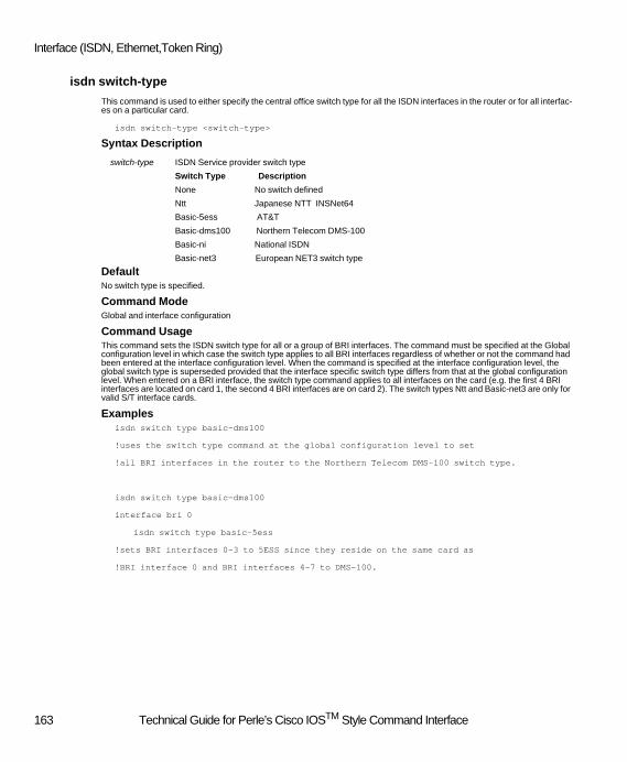
Interface (ISDN, Ethernet,Token Ring)
isdn switch-type
This command is used to either specify the central office switch type for all the ISDN interfaces in the router or for all interfac-es on a particular card.
isdn switch-type <switch-type>
Syntax Description
DefaultNo switch type is specified.
Command ModeGlobal and interface configuration
Command UsageThis command sets the ISDN switch type for all or a group of BRI interfaces. The command must be specified at the Global configuration level in which case the switch type applies to all BRI interfaces regardless of whether or not the command had been entered at the interface configuration level. When the command is specified at the interface configuration level, the global switch type is superseded provided that the interface specific switch type differs from that at the global configuration level. When entered on a BRI interface, the switch type command applies to all interfaces on the card (e.g. the first 4 BRI interfaces are located on card 1, the second 4 BRI interfaces are on card 2). The switch types Ntt and Basic-net3 are only for valid S/T interface cards.
Examplesisdn switch type basic-dms100
!uses the switch type command at the global configuration level to set
!all BRI interfaces in the router to the Northern Telecom DMS-100 switch type.
isdn switch type basic-dms100
interface bri 0
isdn switch type basic-5ess
!sets BRI interfaces 0-3 to 5ESS since they reside on the same card as
!BRI interface 0 and BRI interfaces 4-7 to DMS-100.
switch-type ISDN Service provider switch type
Switch Type Description
None No switch defined
Ntt Japanese NTT INSNet64
Basic-5ess AT&T
Basic-dms100 Northern Telecom DMS-100
Basic-ni National ISDN
Basic-net3 European NET3 switch type
163 Technical Guide for Perle’s Cisco IOSTM Style Command Interface

Supported Command Set Definitions
mac-address
Use the mac-address command to set the hardware MAC layer address for an interface on the router. Use the no or default form of this command to restore the default MAC address.
mac-address <address>
Syntax Description
DefaultNo MAC layer address is set. The router uses its burned in MAC address for the interface
Command Mode Interface configuration
Command UsageThe default MAC address will work in most installations of the router. This command is used in the special case where the administrator wants to control the MAC addresses assigned to the devices on a network.
User-specified MAC addresses are restricted as follows:! For routers equipped with a FastEthernet interface, the server MAC address must be a locally
administered, unicast address. This means that the second digit must be 2, 6, A, or E. For example,0200.0000.0000 would be a valid address, but 0B00.0000.0000 would not.
! For routers equipped with a TokenRing interface, the server MAC address is must be a locallyadministered, individual address. This means that the first digit must be 4, 5, 6, or 7. For example,4000.0000.0000 would be a valid address, but 8000.0000.0000 would not.
Example interface FastEthernet 0
mac-address 0200.0000.1234
!sets the MAC address for a router connected to the Ethernet network.
address 48-bit MAC address written as a dotted triplet of four-digit hexadecimal numbers (e.g. H.H.H where H = <0-FFFF>) or nnnnnnnnnnnn (n= 0-F).
164 Technical Guide for Perle’s Cisco IOSTM Style Command Interface

Interface (ISDN, Ethernet,Token Ring)
media-type
This command specifies the physical connector type for the Ethernet interface. The no or default form of this command will allow the router to autodetect the connector type.
media-type <connector >
{no | default} media-type
Syntax Description
DefaultThe physical connector type is determined automatically.
Command ModeInterface configuration
Command UsageThis command applies only to hardware revisions of the router that include a BNC (10Base2) interface. This command is not required to configure routers that do not have the BNC interface.
Examples The following example sets the physical connector type to RJ-45.
media-type _RJ-45
_name1 , _name2
To specify the names of the B1 and B2 channels on an ISDN BRI interface use the _name1 and _name2 commands. Use the no or default form of this command to return to default channel names.
_name1 <name>
{no | default } _name1
_name2 <name>
{no | default } _name2
Syntax Description
DefaultA default name is assigned based on the card slot number and the BRI interface number.
Command ModeInterface configuration
Command UsageChannel names are case insensitive and must be unique for all BRI interfaces in the router. These names are used for the
connector Specifies the type of physical connector used on the Ethernet interface. The options are _bnc, _rj-45 or _auto-detect
name Assigns a name to the given channel on the BRI interface. The name may contain up 16 alphanumeric characters. Embedded spaces are not allowed.
165 Technical Guide for Perle’s Cisco IOSTM Style Command Interface

Supported Command Set Definitions
Dialout and Group features.
Examples interface BRI 0
_name1 BRI0_01
_name2 BRI0_02
!specifies names for the channels on an ISDN interface
netbios nbf
This command is used to enable the NetBIOS protocol stack.
Netbios nbf
no netbios nbf
DefaultProtocol is disabled.
Command ModeInterface configuration
Command UsageThis command is used to enable the NetBIOS protocol. This protocol is used by some dial-up clients. This command can show up under multiple interfaces (e.g. group_async and dialer), the dialer interface is the one which actually determines the mode of operation for dial-up PPP users.
Examplenetbios nbf
! enables the NetBIOS protocol
no netbios nbf
! disables the NetBIOS protocol
Related Commands_bcp-netbeui local-pool
166 Technical Guide for Perle’s Cisco IOSTM Style Command Interface

Interface (ISDN, Ethernet,Token Ring)
ppp authentication
This command is used to configure the type of PPP (Point to Point) authentication the router will support.
ppp authentication <type> <type>
no ppp authentication
Syntax Description
DefaultNo PPP authentication.
Command ModeInterface configuration
Command UsageThis command defines the type of PPP authentication which will be supported by the router. The user can configure the rout-er to perform CHAP authentication, PAP authentication or allow both. If both methods are enabled on the router, the router will attempt to do CHAP (the more secure method) first, it the client does not support this, PAP will be used. This configura-tion is used when "local" authentication is used on the router. This command must be present in the configuration file when local authentication is used otherwise, PPP clients will not be able to authenticate with the router.
Exampleaaa authentication ppp default local
ppp authentication PAP
! Dial-up clients will be authenticated using the PAP protocol.
aaa authentication ppp default local
no ppp authentication
! dial-up clients will not be able to authenticate with the router.
! This configuration is presented only for the purpose of
! illustrating the command. This is not a practical configuration.
Related Commandsaaa authentication ppp default
type Identifies the type of PPP authentication to use. The following authentication types are supported: PAP -Password Authentication Protocol CHAP - Challenge Handshake Authentication Protocol.
167 Technical Guide for Perle’s Cisco IOSTM Style Command Interface

Supported Command Set Definitions
ppp _async-control
This command is used to configure characters to which the network may be susceptible to.
ppp _async-control <char> <char> …
no ppp _async-control
Syntax Description
DefaultNone.
Command ModeInterface and Group configuration.
Command UsageThis command is used to identify any special byte values which may be harmful to equipment on your wan connection. This is largely a legacy feature. Most equipment today is no longer susceptible to control characters. However, if you have equip-ment (i.e. modems, Terminal Adapters) which are susceptible, you can configure the router not to send the offending bytes out. Any control character defined by this command will be masked so that it does not appear as a control character to any of the equipment along the connection path. On the receiving end, the PPP client will de-mask the character back to its original form. Specify the decimal value of the character. (i.e. if the byte to be masked is "0x1F", enter the value 31).
Exampleppp _async-control 17 19
! This will cause the router to mask the xon/xoff characters.
ppp compression _address
This command is used to configure the PPP negotiation of address compression.
ppp compression _address
no ppp compression _address
DefaultPPP address compression is enabled.
Command ModeInterface and group configuration.
Command UsageThis command is used to enable/disable PPP address compression. If enabled, this will attempt to negotiate the use of ad-dress compression with the other PPP client. If both sides agree, the PPP address field will be omitted from packets. This will reduce the size of the packet by 1 byte.
Exampleinterface dialer 0
ppp compression _address
! router will attempt to negotiate ppp address compression.
char A decimal byte value. The Byte value must be in the range of 0 - 31. Up to 32 values can be specified.
168 Technical Guide for Perle’s Cisco IOSTM Style Command Interface

Interface (ISDN, Ethernet,Token Ring)
interface dialer 0
no ppp compression _address
! router will not attempt to negotiate ppp address compression
! and will refuse a request for ppp address compression
! from the other ppp client.
ppp compression _protocol
This command is used to configure the PPP negotiation of protocol compression.
ppp compression _protocol
no ppp compression _protocol
DefaultPPP protocol compression is enabled.
Command ModeInterface and group configuration.
Command UsageThis command is used to enable/disable PPP protocol compression. If enabled, this will attempt to negotiate the use of pro-tocol compression with the other PPP client. If both sides agree, the PPP protocol field will be omitted from packets. This will reduce the size of the packet by 2 bytes.
Exampleinterface dialer 0
ppp compression _protocol
! router will attempt to negotiate ppp protocol compression.
interface dialer 0
no ppp compression _protocol
! router will not attempt to negotiate ppp protocol compression
!and will refuse a request for ppp protocol compression from the
! other ppp client.
169 Technical Guide for Perle’s Cisco IOSTM Style Command Interface
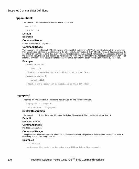
Supported Command Set Definitions
ppp multilink
This command is used to enable/disable the use of multi-link.
multilink
no multilink
DefaultNot enabled.
Command ModeInterface and Group configuration.
Command UsageThis command is used to enable/disable the use of the multilink protocol on a PPP link. Multilink is the ability to use more then one physical interface to send the data to the other end of a connection. If ISDN BRI is being used, this may involve the use of two "B" channels to send data over. The original data is split in two and each half is sent over a separate channel. On the receiving side, the data is re-assembled into the original form. The use of multilink is a negotiable parameter when estab-lishing a PPP connection. Both sides of the connection must agree to this option before it can be used by either side.
Exampleinterface dialer 0
multilink
! Enable the negotiation of multilink on this interface.
interface dialer 0
no multilink
! Disable the negotiation of multilink on this interface.
ring-speed
To specify the ring speed on a Token Ring network use the ring-speed command.
ring-speed <lan-speed>
{ no | default } ring-speed
Syntax Description
DefaultRing speed is not set.
Command ModeInterface configuration
Command UsageThe speed must be set on the router before it is connected to a Token Ring network. Invalid speed settings can result in beaconing on the Token Ring network.
Examples ring-speed 16
!configures the router to function on a 16Mbps Token Ring network.
lan-speed This is the speed (Mbps) on the Token Ring network. The possible values are 4 or 16
170 Technical Guide for Perle’s Cisco IOSTM Style Command Interface

Interface (ISDN, Ethernet,Token Ring)
speed
To specify the speed on an Ethernet network use the speed command.
speed <lan-speed>
{ no | default } speed
Syntax Description
DefaultEthernet speed is auto detected.
Command ModeInterface configuration
Command UsageIn most operating environments the Ethernet speed is auto detected by the router. In some special situations the administra-tor may want to force the speed to be 10Mbps or 100Mbps.
Examples speed 100
!configures the router to function on a 100Mbps Ethernet network.
shutdown (interface)
To disable an interface, use the shutdown command. To restart a disabled interface, use the no form of this command.
shutdown
no shutdown
Syntax Description No parameters
DefaultThe interface is shutdown
Command ModeInterface configuration
Command UsageWhen an ISDN BRI interface is shut down, incoming calls will not be answered and outgoing calls cannot be placed. When an Ethernet or Token Ring interface is shutdown, packets are not received or transmitted on the interface.
Exampleinterface TokenRing 0
ip address 10.10.10.1
!configures the router for a TokenRing network with an IP address
shutdown
!then shuts down the interface
lan-speed This is the speed (Mbps) on the Ethernet network. The possible values are 10, 100, or auto
171 Technical Guide for Perle’s Cisco IOSTM Style Command Interface

Supported Command Set Definitions
IP Access-List Extended Configuration
deny
This command is used to define a deny ip filter. Deny filters define packets which will be refused by the router.
deny <protocol> <source> <destination> <port>
Syntax Description
pattern** - May be any of the following:
ANY - Indicates any ip address.
HOST 1.2.3.4 - Indicates a specific ip host address.
1.2.3.4 0.0.0.255 - address and wild-card bits (wild card bits are the complement of mask).
DefaultNone.
Command Modeip access-list extended configuration
Command UsageThis command defines an ip filter. The user can specify what type of ip protocol to match on, the source ip address, the destination ip address and a specific port number. Incoming packets are compared against this filter definition. If a complete match is found, the packet is discarded. If the packet does not match the filter requirements it will be accepted. Only one deny or permit statement is allowed per filter. To delete the filter the user must exit to the previous command level and issue the "no ip access-list extended" command.
Exampleip access-list extended filter1
deny tcp any any eq 2445
! define a filter which will deny tcp type packets from any ip source with any
! ip destination as long as the port number is equal to "1445"
no ip access-list extended filter1
! deletes the definition of the filter called "filter1"
Protocol The type of protocol to deny. Valid options are ip, icmp, tcp, udp or a protocol number (0 - 255).
Source The source ip pattern** to match. The value of "any" can be used to indicate match on any source ip address.
Destination The destination ip pattern** to match. The value of "any" can be used to indicate match on any destination ip address.
Port The port number to match on in the packet. Can be left out to indicate match on any port.
172 Technical Guide for Perle’s Cisco IOSTM Style Command Interface
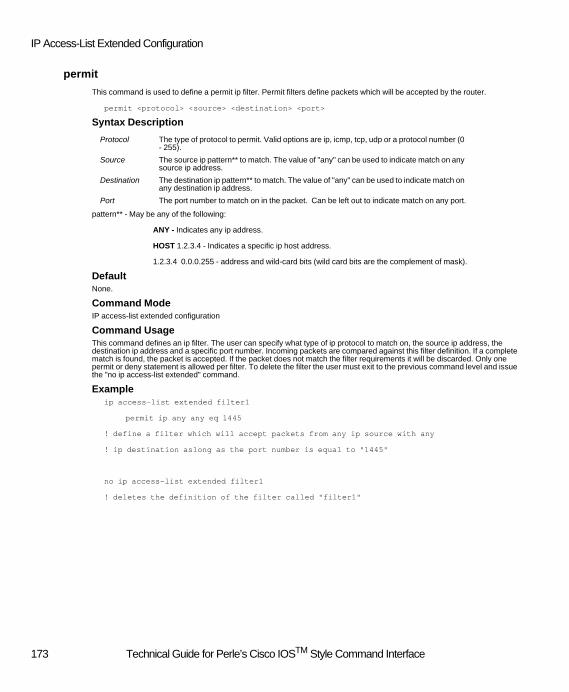
IP Access-List Extended Configuration
permit
This command is used to define a permit ip filter. Permit filters define packets which will be accepted by the router.
permit <protocol> <source> <destination> <port>
Syntax Description
pattern** - May be any of the following:
ANY - Indicates any ip address.
HOST 1.2.3.4 - Indicates a specific ip host address.
1.2.3.4 0.0.0.255 - address and wild-card bits (wild card bits are the complement of mask).
DefaultNone.
Command ModeIP access-list extended configuration
Command UsageThis command defines an ip filter. The user can specify what type of ip protocol to match on, the source ip address, the destination ip address and a specific port number. Incoming packets are compared against this filter definition. If a complete match is found, the packet is accepted. If the packet does not match the filter requirements it will be discarded. Only one permit or deny statement is allowed per filter. To delete the filter the user must exit to the previous command level and issue the "no ip access-list extended" command.
Exampleip access-list extended filter1
permit ip any any eq 1445
! define a filter which will accept packets from any ip source with any
! ip destination aslong as the port number is equal to "1445"
no ip access-list extended filter1
! deletes the definition of the filter called "filter1"
Protocol The type of protocol to permit. Valid options are ip, icmp, tcp, udp or a protocol number (0 - 255).
Source The source ip pattern** to match. The value of "any" can be used to indicate match on any source ip address.
Destination The destination ip pattern** to match. The value of "any" can be used to indicate match on any destination ip address.
Port The port number to match on in the packet. Can be left out to indicate match on any port.
173 Technical Guide for Perle’s Cisco IOSTM Style Command Interface

Supported Command Set Definitions
IPX Access-List Extended Configurtation
deny
This command is used to define a deny ipx filter. Deny filters define packets which will be refused by the router.
deny <protocol> <source net> <source socket> <destination net> <destination socket>
Syntax Description
DefaultNone.
Command Modeipx access-list extended configuration
Command UsageThis command defines an ipx filter. The user can specify what type of ipx protocol to match on, the source ipx network and socket number and the destination ipx network and socket number. Incoming packets are compared against this filter defini-tion. If a complete match is found, the packet is discarded. If the packet does not match the filter requirements it will be ac-cepted. Only one deny or permit statement is allowed per filter. To delete the filter the user must exit to the previous command level and issue the "no ipx access-list extended" command.
Exampleipx access-list extended filter1
deny spx any 1111 any 2222
! define a filter which will deny spx type packets from any ipx network
! going to any ipx network as long as the source socket is "1111" and
! the destination socket is "22222"
no ipx access-list extended filter1
! deletes the definition of the filter called "filter1"
Protocol The type of protocol to deny. Valid options are any, ncp, rip, sap, spx or a protocol number (0 - 255).
Source net The source ipx network to match. The value of "any" can be used to indicate match on any source ip address.
Source socket The source socket number or “all”. Socket a number in the range 0 - FFFF. (0 is the same as “all”)
Destination net
The destination ipx address to match. The value of "any" can be used to indicate match on any destination ipx address.
Destination socket
The destination socket number. Must be a number in the range 0 - FFFF
174 Technical Guide for Perle’s Cisco IOSTM Style Command Interface

IPX Access-List Extended Configurtation
permit
This command is used to define a permit ipx filter. Permit filters define packets which will be accepted by the router.
permit <protocol> <source net> <source socket> <destination net> <destination socket>
Syntax Description
DefaultNone.
Command Modeipx access-list extended configuration
Command UsageThis command defines an ipx filter. The user can specify what type of ipx protocol to match on, the source ipx network and socket and the destination ipx network and socket. Incoming packets are compared against this filter definition. If a complete match is found, the packet is accepted. If the packet does not match the filter requirements it will be discarded. Only one permit or deny statement is allowed per filter. To delete the filter the user must exit to the previous command level and issue the "no ipx access-list extended" command.
Exampleipx access-list extended filter1
permit any any 1234 any 2451
! define a filter which will accept any ipx packet from any ipx network,
! a source socket number of "1234", destined to any ipx network with a
! destination socket number of "2451"
no ipx access-list extended filter1
! deletes the definition of the filter called "filter1"
Protocol The type of protocol to permit. Valid options are any, ncp, rip, sap, spx or a protocol num-ber (0 - 255).
Source net The source ipx network to match. The value of "any" can be used to indicate match on any source ip address.
Source socket The source socket number. Must be a number in the range 0 - FFFF
Destination net
The destination ipx address to match. The value of "any" can be used to indicate match on any destination ipx address.
Destination socket
The destination socket number. Must be a number in the range 0 - FFFF
175 Technical Guide for Perle’s Cisco IOSTM Style Command Interface

Supported Command Set Definitions
Key Chain Configuration
key
This command is used to enter a specific key configuration mode on the router.
key <number>
Syntax Description
Command ModeKey-chain configuration
Command UsageThis command is used to enter the configuration mode for a specific key. It moves the command from "key-chain" configura-tion" to "key" configuration.
Key Configuration
accept-lifetime
This command is used to configure the life time of the key being defined.
accept-lifetime <start time> <start date> <duration>
Syntax Description
Command ModeKey configuration
Command UsageThis command is used to enter the accept life time of the key being configured. To delete this key the user must step back to the previous command level and issue the "no key" command.
ExampleKey chain security
Key 1
accept-lifetime 23:59:59 jan 1 2000 infinite
! This defines an accept life time which starts on January 1, 2000 at
! 23:59:59 and will
number The key id of the key being defined. Valid range is 0 - 255.
start time The time of day when the key is to start being accepted. (hh:mm:ss).
start date The day and month when the key is to become accepted.
duration Can be entered as a time and date, a duration (in seconds) or "infinite"
176 Technical Guide for Perle’s Cisco IOSTM Style Command Interface

Key Configuration
key-string
This command is used to enter the actual value of the key.
key-string <value>
Syntax Description
Command ModeKey configuration
Command UsageThis command is used to enter the actual value of the key being configured. To delete this key the user must step back to the previous command level and issue the "no key" command.
ExampleKey chain security
Key 1
Key-string 12345678
! This sequence defines a key chain which has one key with the value of 12345678.
key chain security
no key 1
! Deletes the configuration of key number 1.
send-lifetime
This command is used to configure the length of time that this key will be sent out by the router.
send-lifetime <start time> <start date> <duration>
Syntax Description
Command ModeKey configuration
Command UsageThis command is used to enter the send life time of the key being configured. To delete this key the user must step back to the previous command level and issue the "no key" command.
value The actual value of the key. The key can be up to 16 characters in length.
start time The time of day when the key is to become active. (hh:mm:ss).
start date The day and month when the key is to become active.
duration Can be entered as a time and date, a duration (in seconds) or "infinite"
177 Technical Guide for Perle’s Cisco IOSTM Style Command Interface

Supported Command Set Definitions
ExampleKey chain security
Key 1
send-lifetime 23:59:59 jan 1 2000 infinite
! This defines a life time which starts on January 1, 2000 at 23:59:59
!and will never expire.
key chain security
no key 1
! Deletes the configuration of key number 1.
never
! expire.
key chain security
no key 1
! Deletes the configuration of key number 1.
178 Technical Guide for Perle’s Cisco IOSTM Style Command Interface
Line Interface Configuration
Line Interface Configuration
modem bad
To disable a modem, use the modem bad command. Use the no form of this command to enable the modem.
modem bad
no modem bad
Syntax Description No parameters
DefaultModem is enabled.
Command ModeLine Interface configuration
Command UsageThis command is used to disable individual or groups of modems on the router. This command takes effect immediately and drops any active call on the modem(s).
Examples line tty 1 - 8
modem bad
disables 8 modems.
modem _name
To specify the name of a modem, use the _name command. The no form of this command sets the modem back to its default name.
modem _name <name>
no modem _name
Syntax Description
DefaultA default name is assigned based on the slot number where the modem is located.
Command ModeLine Interface configuration
Command UsageThis command applies only to a single modem resource.
name Specifies the name of the modem. The name consists of up to 16 alphanumeric charac-ters. Embedded spaces are not allowed
179 Technical Guide for Perle’s Cisco IOSTM Style Command Interface

Supported Command Set Definitions
Examples line tty 1
modem _name FIRST-MODEM
specifies the name FIRST_MODEM for modem 1.
script reset
Use the script reset command to execute a specified chat script any time a modem is reset. Use the no form of this command to disable this feature.
script reset <script_name>
no script reset
Syntax Description
DefaultNo modem script is specified.
Command ModeLine Interface configuration
Command UsageThis command is used in conjunction with the chat-script command to send customized AT initialization strings to the mo-dems. If the AT initialization string defined for a chat-script is added, modified, or deleted, any active call on a modem which utilizes that chat-script will be dropped.
Examples chat-script line1_ATstring "AT&F"
line tty 1
script reset line1_ATstring
!uses the chat-script to set a modem initialization string for a modem.
Related Commandschat-script
script_name Name of the chat script to be executed any time the modem on this line is reset. The script name can consist of up to 30 alphanumeric characters. Embedded spaces are not al-lowed
180 Technical Guide for Perle’s Cisco IOSTM Style Command Interface

Override-Standard Profile Configuration
Override-Standard Profile Configuration
Callback alternate
This command is used to configure a specific user's callback attributes.
callback alternate <phone number>
no callback alternate
Syntax Description
DefaultNone.
Command Modeoverride-standard-profile configuration.
Command UsageThis command is used to configure a second phone number which can be used to call the user back at. This phone number is used in conjunction with the "username name callback-dialstring phone number" command. When a fixed callback is de-fined using the callback-dialstring parameter, a second phone number can be configured for callback using the "callback alternate" command. When the callback negotiated with the dial-up client, the client will be presented a choice of both phone number from which he may chose one on which he wishes to be called back at. This is used when a dial-up client has two locations from which he calls in. (i.e. office and home). By configuring both numbers on the router, the user will select the appropriate loaction to be called back at dynamically at connect time. Please note that in order to use this feature, the client must support the "list" feature of the CBCP (Call Back Control Protocol).
Exampleusername allover callback-dialstring 9055551234567 password outalot
_userdb allover
override-standard-profile
callback alternate 9055557654321
! This sets up a user called "allover" with a password of "outalot"
! Call back has been configured for this user.
! The user will have a choice of being called back at "9055551234567"
! or at "9055557654321"
_userdb allover
override-standard-profile
no callback alternate
! This removes the second number for callback for user "allover"
Related Commandsusername callback-dialstring
callback roaming
phone number An alternate phone number at which the user can be called back.
181 Technical Guide for Perle’s Cisco IOSTM Style Command Interface

Supported Command Set Definitions
Callback exclusive
This command is used to configure global or specific user callback attributes.
callback exclusive
no callback exclusive
DefaultCallback group is not exclusive.
Command Modeoverride-standard-profile and standard-profile configuration.
Command UsageThis command is used to restrict which group will be used for the callback. When configuring the user via the "username" command, the user may specify a "callback-rotary <group>" which they would like to use with the callback. This would cause the router to select a line and modem (for analog calls) from the members of the specified group. If callback exclusive is configured, the resources must come from the members of the group. If this command is not issued, the router will attempt to satisfy the request by selecting resources from the group however if the resources in the group are not currently available, the router will attempt to obtain the required resource from the general pool of resources.
Examplecallback-rotary accounting
callback exclusive
! when performing a callback, the router will use the resources associated with the group
! "accounting".
callback-rotary accounting
no callback exclusive
! when performing a callback, the router will attempt to use the resources
! associated with the group "accounting". If unable to obtain resources
! from the group, the main resource pool will be used.
Related Commandsusername
callback alternate
callback roaming
182 Technical Guide for Perle’s Cisco IOSTM Style Command Interface

Technical Guide for Perle’s Cisco IOSTM Style Command Line Interface
Callback roaming
This command is used to configure global or specific user callback attributes.
callback roaming
no callback roaming
DefaultNot enabled.
Command Modeoverride-standard-profile and standard-profile configuration.
Command UsageThis command is used to enable the roaming callback for this user. If enabled, after dialing into the router, a user will be given the choice of having the router call him back. One common use for this feature is when the user wishes to have the charges for the call be applied to the router side. This provides for the centralization of phone charges.
Examplecallback roaming
! enables this feature.
no callback roaming
! disables this feature.
Related Commandsusername
callback exclusive
callback alternate
Technical Guide for Perle’s Cisco IOSTM Style Command Interface 183

Supported Command Set Definitions
inactive
This command is used to configure a global or specific user's inactivity timeout value.
inactive <time>
no inactive
Syntax Description
DefaultNot enabled.
Command Modeoverride-standard-profile and standard-profile configuration.
Command UsageThis command is used to enter an inactivity timeout for a user. The time is entered in minutes. If the dial-up connection is inactive for this duration of time, the connection will be dropped by the router. Please note that depending on the protocol used, there may be activity on the line which is not directly generated by the user. This includes things such as keep alive watchdogs which may be used by the underlying protocol to detect the connection status. If the protocol in use by the user employs such messages, the connection may never be dropped due to inactivity.
Exampleinactive 30
! if no activity is detected on the connection for 30 minutes, the connection
! will be terminated.
no inactive
! connection will not be dropped due to inactivity on the line.
time Time in minutes. Valid range is 0 - 65535.
184 Technical Guide for Perle’s Cisco IOSTM Style Command Interface

Technical Guide for Perle’s Cisco IOSTM Style Command Line Interface
macaddr
This command is used to configure a specific MAC address for a user.
macaddr {ethernet | tokenring} <address>
no macaddr
Syntax Description
DefaultNot enabled.
Command Modeoverride-standard-profile configuration.
Command UsageThis command is used to assign a specific MAC address to a dial-up user. When the user connects using a BCP or native NetBeui client, the MAC address defined by this command will be assigned to the user. If this command is not specified, the MAC address will be taken from the pool defined on the server or it may be specified by the dial-up client. (see "_bcp-netbeui local-pool" and "_bcp mac-address-client-specified").
If the user is on an Ethernet lan, the Users’s MAC address is restricted to a locally administered, unicast Ethernet address. This means that the second digit must be 2, 6, A or E. For example, 020000000000 is a valid address. If the user is on a Token Ring lan, the User’s MAC Addressis restricted to a locally administered, individual Token Ring address. This means that the first digit must be 4,5,6 or 7. For example, 400000000000 is a valid address.
Examplemacaddr ethernet 022030405060
! when this user dials in, they will be assigned the MAC address "022030405060".
no macaddr
! when this user dials in, they will either specify the MAC address they wish
!to use or have an address provided to them
!from the pool
Related Commands_bcp mac-address-client-specified
_bcp-netbeui local-pool
address A valid MAC address.
Technical Guide for Perle’s Cisco IOSTM Style Command Interface 185

Supported Command Set Definitions
maximum
This command is used to configure a global or specific user's maximum connect timeout.
maximum <time>
no maximum
Syntax Description
DefaultNot enabled.
Command Modeoverride-standard-profile and standard-profile configuration.
Command UsageThis command is used to enter a maximum connect timeout for a user. The time is entered in minutes. The dial-up connec-tion will be terminated when this time elapses.
Examplemaximum 60
! This user will be allowed to connect for a maximum of 60 minutes.
no maximum
! connection will be allowed to stay connected forever.
time Time in minutes. Valid range is 0 - 65535.
186 Technical Guide for Perle’s Cisco IOSTM Style Command Interface

Technical Guide for Perle’s Cisco IOSTM Style Command Line Interface
protocol
This command is used to enable/disable protocol stacks.
protocol <protocol>
no protocol <protocol>
Syntax Description
DefaultIP and IPX are enabled.
ARA, BCP and NetBIOS are not enabled.
Command Modeoverride-standard-profile and standard-profile configuration.
Command UsageThis command is used to enable/disable the NCP (Network Control Protocol) negotiation by PPP of the protocol stacks on the router. The command can be entered multiple times, once for each protocol. The no version of the command will disable the specified protocol. You can not enable a protocol at the user level if it has not been enabled at the global ("_standard-profile") level. If the user wishes to use the GUI configuration tool provided with the router, one of the ip or ipx protocols must be enabled on the router.
Example_standard-profile
protocol ip
protocol netbios
_userdb user2
override-standard-profile
no protocol netbios
! This enables the protocols ip and netbios globally and for user "user2"
! the netbios protocol is disabled.
protocol The name of the protocol to enable or disable. Valid protocols include;
ara -Apple Remote Access
bcp -Bridge Control Protocol
ip -Internet Protocol
ipx -Internet Packet eXchange
netbios -Also know as NetBeui
Technical Guide for Perle’s Cisco IOSTM Style Command Interface 187

Supported Command Set Definitions
virtual
This command is used to configure a global or specific user as a virtual (spoofing) client.
virtual
no virtual
DefaultNot enabled.
Command Modeoverride-standard-profile and standard-profile configuration.
Command UsageThis command is used to configure a client or clients (if used under the _standard-profile) which will be making use of spoof-ing. Spoofing is where the dial-up client will drop the connection when inactivity exists in order to save connection charges. When the client drops the connection, if the user is defined as a "virtual" client, the ip address used by the client will be re-served on the router. When the client dials back in, he will be assigned the same ip address back. If an inactivity timer or a maximum connect timer has been configured on the router, when these expire, the session is dropped and the ip address is returned to the ip pool. Please note that if no inactivity or maximum connect timers are configured, the session will be re-served for this client indefinitely.
Example_userdb economical
override-standard-profile
maximum 60
virtual
! This sets up user "economical" as a virtual client who can drop his
! connection at any time and his session will be logically maintained. When
!60 minutes elapse, the session will be ended.
_userdb economical
override-standard-profile
maximum 60
no virtual
! If the user drops his connection, the session will be freed up immediately.
188 Technical Guide for Perle’s Cisco IOSTM Style Command Interface

Technical Guide for Perle’s Cisco IOSTM Style Command Line Interface
server-filters
This command is used to enable/disable the augmenting of interface filters with specific user filters.
server-filters
no server-filters
DefaultNo augmenting of interface filters.
Command Modeoverride-standard-profile and standard-profile configuration.
Command UsageThis command is used to enable or disable the use of filters defined at the user level for dial-up clients. Filters defined under the interface are always used first, if no match is found and the user filters have been enabled, they will be checked next. The no version of the command, enables the definition of local filters for the dial-up clients.
Example_userdb user1
override-standard-profile
no server-filters
ip access-group filter1
! This sets up user1 with some additional filters which will be checked if
!no match is found on the filters defined on the interface
Technical Guide for Perle’s Cisco IOSTM Style Command Interface 189

Supported Command Set Definitions
lan-to-lan
This command is used to configure a user as a lan to lan connection.
lan-to-lan
no lan-to-lan
DefaultUser is not a lan-to-lan user.
Command ModeOverride-standard-profile configuration.
Command UsageThis command is used to configure a user as a lan-to-lan user. This implies that the device on the other end of this connection is a router. This router is treated differently from normal dial-up users. When the user is defined as a lan-to-lan user, the following functions can be enabled;
· Connection can be initiated from the router to this user.
· User may require this router to authenticate with it.
· A virtual connection can be configured for this user.
· RIPs may be exchanged with this type of user.
Example_userdb router1
lan-to-lan
! Defines "router1" as a lan-to-lan connection
_userdb router1
no lan-to-lan
! "router1" is no longer defined as a lan-to-lan connection
Related Commandsl2l-auto-connect
l2l-id
l2l-password
l2l-calltype
l2l-phone
l2l-channel
l2l-virtual
l2l-inactive
l2l-minimum
l2l-reconnect
l2l-rip send
l2l-rip receive
190 Technical Guide for Perle’s Cisco IOSTM Style Command Interface

Technical Guide for Perle’s Cisco IOSTM Style Command Line Interface
l2l-auto-connect
This command is used to configure an attribute of a lan to lan user connection.
l2l-auto-connect
no l2l-auto-connect
DefaultNo autoconnect.
Command ModeOverride-standard-profile configuration.
Command UsageThis command is used to configure the auto connect feature for a lan to lan user. When enabled, this feature will cause the lan to lan connection to be established at power up time. This type of user is intended to stay connected as long as the router is up.
Example_userdb router1
l2l-auto-connect
! Define a "permanent" connection to "router1"
_userdb router1
no l2l-auto-connect
! "router1" is no longer defined as a "permanent" connection
Related Commandslan-to-lan
l2l-id
l2l-password
l2l-calltype
l2l-phone
l2l-channel
l2l-virtual
l2l-inactive
l2l-minimum
l2l-reconnect
l2l-rip send
l2l-rip receive
Technical Guide for Perle’s Cisco IOSTM Style Command Interface 191

Supported Command Set Definitions
l2l-id
This command is used to configure a user id for a lan to lan user connection.
l2l-id <name>
no l2l-id
Syntax Description
DefaultNone.
Command ModeOverride-standard-profile configuration.
Command UsageThis command is used to configure the user id for the lan to lan connection. This is the user id which is used to log on to the other router we are connecting to. This id will be required whenever the other router requests us to authenticate. This hap-pens when we initiate the call and with some routers it can also be requested when the router dials into us.
Example_userdb router1
l2l-id router2
! Define a user id of "router2" which will be used if router1 requests
!us to authenticate.
_userdb router1
no l2l-id
! Removes the user id for router1.
Related Commandslan-to-lan
l2l-auto-connect
l2l-password
l2l-calltype
l2l-phone
l2l-channel
l2l-virtual
l2l-inactive
l2l-minimum
l2l-reconnect
l2l-rip send
l2l-rip receive
name A user id to be used to log into a remote router. The name can be up to 16 characters long.
192 Technical Guide for Perle’s Cisco IOSTM Style Command Interface

Technical Guide for Perle’s Cisco IOSTM Style Command Line Interface
l2l-password
This command is used to configure a user password for a lan to lan user connection.
l2l-password <password>
no l2l-password
Syntax Description
DefaultNone.
Command ModeOverride-standard-profile configuration.
Command UsageThis command is used to configure the password associated with the user id for the lan to lan connection. The user id and password combination is used to log on to the other router we are connecting to. This will be required whenever the other router requests us to authenticate. This happens when we initiate the call and with some routers it can also be requested when the router dials into us.
Example_userdb router1
l2l-id router2
l2l-password kids
! Define a user id of "router2" with a password of "kids".
_userdb router1
no l2l-password
! Removes the password for router1.
Related Commandslan-to-lan
l2l-auto-connect
l2l-id
l2l-calltype
l2l-phone
l2l-channel
l2l-virtual
l2l-inactive
l2l-minimum
l2l-reconnect
l2l-rip send
l2l-rip receive
password A user password which is associated with the user id to be used to log into a remote rout-er. The password can be up to 16 characters long.
Technical Guide for Perle’s Cisco IOSTM Style Command Interface 193

Supported Command Set Definitions
l2l-calltype
This command is used to configure the type of call to place for this lan to lan user connection.
l2l-calltype <type>
no l2l-calltype
Syntax Description
DefaultDigital.
Command ModeOverride-standard-profile configuration.
Command UsageThis command is used to configure the type of call to place for this user. When the router needs to initiate a call to this user, it needs to know if a modem will be required for the call. This command specifies the type of connection and therefore the resources which will be required for the connection.
Example_userdb router1
l2l-calltype digital
! Define this as a digital call. No modem will be required.
_userdb router1
no l2l-calltype digital
! Removes the calltype. Router will not place a call to this user.
Related Commandslan-to-lan
l2l-auto-connect
l2l-id
l2l-password
l2l-phone
l2l-channel
l2l-virtual
l2l-inactive
l2l-minimum
l2l-reconnect
l2l-rip send
l2l-rip receive
type The type of call to place. The valid options are; "digital" or "analog".
194 Technical Guide for Perle’s Cisco IOSTM Style Command Interface

Technical Guide for Perle’s Cisco IOSTM Style Command Line Interface
l2l-phone
This command is used to configure the phone number to be dialed when the router needs to connect to this lan to lan user.
l2l-phone <number> <phone number>
no l2l-phone
Syntax Description
DefaultNone.
Command ModeOverride-standard-profile configuration.
Command UsageThis command is used to configure the phone number to be dialed when placing a call to this user. Make sure that you in-clude all digits required to make the call. In some cases, a "9" is required in front of the number when dialing out on a BRI line. Find out what the requirements for placing a call are for your phone system and include any required pre-fixes in this phone number. If a second phone number is provided, multilink is enabled and it is used to place the second call for the connection.
Example_userdb router1
l2l-phone 1 915552223333
! Configure a primary phone number which includes the following. A 9, used
! to initiate a call on this BRI line. A 1, used to indicate that this is a
! long distance call. The area code of 555 and finally the actual
! phone number of 222-3333.
_userdb router1
no l2l-phone
! Removes all phone numbers associated with this user. Router will not
! place a call to this user.
Related Commandslan-to-lan l2l-auto-connect l2l-id
l2l-password l2l-calltype l2l-channel
l2l-virtual l2l-inactive l2l-minimum
l2l-reconnect l2l-rip send l2l-rip receive
Number Indicates if this specified the primary or secondary phone number. A value of 1 indicates primary, a 2 indicates secondary.
Phone number The phone number to call. Include all digits required to make the call.
Technical Guide for Perle’s Cisco IOSTM Style Command Interface 195

Supported Command Set Definitions
l2l-channel
This command is used to reserve a specific BRI channel for this lan to lan user.
l2l-channel <number> <name>
no l2l-channel
Syntax Description
DefaultNone.
Command ModeOverride-standard-profile configuration.
Command UsageThis command is used to reserve up to 2 channels to be used when placing a call to this user. If a second channel is re-served, multilink PPP is enabled.
Example_userdb router1
l2l-channel 1 line1
! Reserves "line1" as the primary line resource to use if making a call to this user.
_userdb router1
no l2l-channel
! Removes all channels reserved for this user.
Related Commandslan-to-lan
l2l-auto-connect
l2l-id
l2l-password
l2l-calltype
l2l-phone
l2l-virtual
l2l-inactive
l2l-minimum
l2l-reconnect
l2l-rip send
l2l-rip receive
Number Indicates primary or secondary channel. A value of 1 indicates this is a primary channel. A value of 2, indicates that this is a secondary channel.
name The name of the channel to be used to call out on.
196 Technical Guide for Perle’s Cisco IOSTM Style Command Interface

Technical Guide for Perle’s Cisco IOSTM Style Command Line Interface
l2l-virtual
This command is used to configure this lan to lan user as supporting a virtual connection.
l2l-virtual
no l2l-virtual
DefaultNone virtual.
Command ModeOverride-standard-profile configuration.
Command UsageThis command is used to define the connection as one which can be spoofed. This refers to the ability of either side of the connection to drop the physical link but maintain a logical session. The physical connection can be restored when required (timer elapses or there is data to be sent). This can be used to reduce phone charges.
Example_userdb router1
l2l-virtual
! Defines this connection as a virtual connection.
_userdb router1
no l2l-virtual
! When this connection drops, all internal resources will be freed up.
Related Commandslan-to-lan
l2l-auto-connect
l2l-id
l2l-password
l2l-calltype
l2l-phone
l2l-channel
l2l-inactive
l2l-minimum
l2l-reconnect
l2l-rip send
l2l-rip receive
Technical Guide for Perle’s Cisco IOSTM Style Command Interface 197

Supported Command Set Definitions
l2l-inactive
This command is used to configure an inactivity time out for this lan to lan user.
l2l-inactive <time>
no l2l-inactive
Syntax Description
DefaultNo inactivity time out.
Command ModeOverride-standard-profile configuration.
Command UsageThis command is used to define the inactivity timeout for this connection. If there is no activity on the connection for this length of time, the router will drop the connection. Please note that some protocols generate activity on the line without user input. This usually consists of “keep alive" or "watchdog" messages. Some applications or routing protocols may also gener-ate traffic on the line. If the client is using a protocol or application which is generating this type of traffic, the connection may never drop due to inactivity.
Example_userdb router1
l2l-virtual
! Defines this connection as a virtual connection.
_userdb router1
no l2l-virtual
! When this connection drops, all internal resources will be freed up.
Related Commandslan-to-lan
l2l-auto-connect
l2l-id
l2l-password
l2l-calltype
l2l-phone
l2l-channel
l2l-virtual
l2l-minimum
l2l-reconnect
l2l-rip send
l2l-rip receive
time The inactivity time in minutes.
198 Technical Guide for Perle’s Cisco IOSTM Style Command Interface

Technical Guide for Perle’s Cisco IOSTM Style Command Line Interface
l2l-minimum
This command is used to configure a minimum connect time for this lan to lan user.
l2l-minimum <time>
no l2l-minimum
Syntax Description
DefaultNo minimum connect time.
Command ModeOverride-standard-profile configuration.
Command UsageThis command is used to define the minimum connect time for this user. After a connection is established to this user, it will not be dropped due to inactivity for the duration specified by this command. This can be used to ensure that enough time passes after a connection is established to collect or distribute certain data. An example may the setting the minimum con-nect time to 2 minutes in order to give the router enough time to send out a few (up to 4) RIP messages and receive some RIP messages from the other routers. This will ensure that the router's routing tables are updated each time the connection is made.
Example_userdb router1
l2l-virtual
l2l-minimum 3
! This connection will be maintained for a minimum of 3 minutes after it is established.
_userdb router1
l2l-virtual
no l2l-minimum
! Connection will be dropped whenever the inactivity timer kicks in.
Related Commandslan-to-lan l2l-auto-connect l2l-id
l2l-password l2l-calltype l2l-phone
l2l-channel l2l-virtual l2l-inactive
l2l-reconnect l2l-rip send l2l-rip receive
time The minimum connect time in minutes.
Technical Guide for Perle’s Cisco IOSTM Style Command Interface 199

Supported Command Set Definitions
l2l-reconnect
This command is used to configure a re-connect time for this lan to lan user.
l2l-reconnect <time>
no l2l-reconnect
Syntax Description
DefaultNo re-connect time.
Command ModeOverride-standard-profile configuration.
Command UsageThis command is used to define the re-connect time for this user. After a virtual connection dropped, the router will wait for this amount of time and then re-establish the connection. An example of how this can be used could be used would be the forcing of a periodic re-connect for the purpose of getting the routing tables updated.
Example_userdb router1
l2l-virtual
l2l-reconnect 60
l2l-minimum 3
! This connection will be established each 60 minutes and be maintained for a minimum of 3
! minutes after it is established.
_userdb router1
l2l-virtual
no l2l-reconnect
! Connection will only be re-established by the router if there is
!data to be sent to this user.
Related Commandslan-to-lan l2l-auto-connect l2l-id
l2l-password l2l-calltype l2l-phone
l2l-channel l2l-virtual l2l-inactive
l2l-minimum l2l-rip send l2l-rip receive
time The re-connect time in minutes.
200 Technical Guide for Perle’s Cisco IOSTM Style Command Interface

Technical Guide for Perle’s Cisco IOSTM Style Command Line Interface
l2l-rip send
This command is used to configure what type of RIP packets will be sent on this lan to lan connection.
l2l-rip send version <version>
no l2l-rip send
Syntax Description
DefaultRIP version 1.
Command ModeOverride-standard-profile configuration.
Command UsageThis command is used to configure the type of RIP packet which will be sent by the router for this user. The valid options are; RIP version 1, does not include subnet mask information; RIP version 2 or a RIP version 1 compatible which has subnet information but does not use multicast addresses. This setting should match the type of RIPs the routers on the other side of the connection can support. The no version of the command prevents RIPs from being sent by the router.
Example_userdb router1
l2l-rip send version 2
! sets the type of RIPs sent out by the router on this connection to version 2
_userdb router1
no l2l-rip send version
! prevents the router from sending out RIP packets on this lan to lan connection.
Related Commandslan-to-lan l2l-auto-connect l2l-id
l2l-password l2l-calltype l2l-phone
l2l-channel l2l-virtual l2l-inactive
l2l-minimum l2l-reconnect l2l-rip receive
version The type of RIP packet to send. Valid options are;
1 -RIP type 1
2 -RIP type 2
1 2 -RIP 1 compatible
Technical Guide for Perle’s Cisco IOSTM Style Command Interface 201

Supported Command Set Definitions
l2l-rip receive
This command is used to configure what type of RIP packets will be accepted on this lan to lan connection.
l2l-rip receive version <version>
no l2l-rip receive
Syntax Description
DefaultRIP version 1 compatible.
Command ModeOverride-standard-profile configuration.
Command UsageThis command is used to configure the type of RIP packet which will be accepted by the router for this user. The valid options are; RIP version 1, does not include subnet mask information; RIP version 2 or a RIP version 1 compatible which has subnet information but does not use multicast addresses. This setting should match the type of RIPs the routers on the other side of the connection will be sending. The no version of the command prevents RIPs from being accepted by the router for this user.
Example_userdb router1
l2l-rip receive version 2
! sets the type of RIPs accepted by the router on this connection to version 2
_userdb router1
no l2l-rip receive version
! prevents the router from accepting RIP packets on this lan to lan connection.
Related Commandslan-to-lan l2l-auto-connect l2l-id
l2l-password l2l-calltype l2l-phone
l2l-channel l2l-virtual l2l-inactive
l2l-minimum l2l-reconnect l2l-rip send
version The type of RIP packet to send. Valid options are;
1 -RIP type 1
2 -RIP type 2
1 2 -RIP 1 compatible
202 Technical Guide for Perle’s Cisco IOSTM Style Command Interface

Technical Guide for Perle’s Cisco IOSTM Style Command Line Interface
Router Configuration
network
This command is used to define the ip network number for which RIPs will be enabled.
network <network #>
no network <network #>
Syntax Description
DefaultNo RIP processing
Command ModeRouter configuration
Command UsageThis command is used to define an ip network number for which RIPs are to be sent and received. If bootp or rarp is being used to obtain the ip address of the lan interface, the user can enter an ip network address of all zeros to enable RIP process-ing on the lan interface.
Examplenetwork 101.101.0.0
! enables RIP handling on ip network 101.101
no network 101.101.0.0
! disables RIP handling on ip network 101.101
Related Commandsrouter rip
network # The ip network number on which to send and process RIPs
Technical Guide for Perle’s Cisco IOSTM Style Command Interface 203

Supported Command Set Definitions
Standard-Profile Configuration
Callback-rotary
This command is used to configure global user callback attributes.
callback-rotary <group>
no callback-rotary
Syntax Description
DefaultUse the main resource pool.
Command ModeStandard-profile configuration.
Command UsageThis command is used to configure which group will be used for the callback. When configuring the callback the user would use this command to specify which group they would like to use with the callback. This would cause the router to select a line and modem (for analog calls) from the members of the specified group. If callback exclusive is configured, the resources must come from the members of the group specified in this command. If the "callback exclusive" command is not issued, the router will attempt to satisfy the request by selecting resources from the group however if the resources in the group are not currently available, the router will attempt to obtain the required resource from the general pool of resources.
Examplecallback-rotary accounting
callback exclusive
! when performing a callback, the router will use the resources associated
! with the group "accounting".
callback-rotary accounting
no callback exclusive
! when performing a callback, the router will attempt to use the resources
! associated with the group "accounting". If unable to obtain resources
! from the group, the main resource pool will be used.
Related Commandsusername
callback exclusive
callback roaming
callback alternate
Group The name of a group which has been defined as a "callback" group.
204 Technical Guide for Perle’s Cisco IOSTM Style Command Interface

Technical Guide for Perle’s Cisco IOSTM Style Command Line Interface
userdb Configuration
admin
This command is used to configure additional parameters for a user defined using the "username" command.
admin
no admin
DefaultNo admin.
Command Modeuserdb configuration.
Command UsageThis command is used to make a user "privileged". A privileged user can execute commands which are not available to non-privileged users. To gain access to the privileged commands, a user must execute the "enable" command first. This is the entry point to these commands. If a "box secret" has been configured, the user will be prompted for a the password before he/she is granted access to the privileged commands.
A user which is attempting to configure the router via the GUI manager program also needs to be defined as an admin user.
This privilege can also be set by an external source such as a Radius host.
Example_userdb user1
admin
! Identifies the user "user1" as having administrative rights.
_userdb user1
no admin
! removes the administrative rights from user "user1".
Related Commandsenable
enable secret
Technical Guide for Perle’s Cisco IOSTM Style Command Interface 205

Supported Command Set Definitions
disabled
This command is used to configure additional parameters for a user defined using the "username" command.
disabled
no disabled
DefaultUser is enabled.
Command Modeuserdb configuration.
Command UsageThis command is used to disable a user configured in the internal database. To enable a user who has been disabled, use the no version of the command. A disabled user will not be deleted from the internal database, but they will not get authenti-cated by the router if they attempt to dial in.
Example_userdb user1
disabled
! disable user "user1"
_userdb user1
no disabled
! re-enable user "user1"
department
This command is used to configure additional parameters for a user defined using the "username" command.
department <department name>
no department
Syntax Description
DefaultNone.
Command Modeuserdb configuration.
Command UsageThis command is used to associate a department name with a user. This information is only used in status displays.
Example_userdb user1
department accounting
! Identifies the user "user1" as being part of the accounting department.
department name
The name of the department to which the user belongs. The name can be up to 16 char-acters.
206 Technical Guide for Perle’s Cisco IOSTM Style Command Interface

Technical Guide for Perle’s Cisco IOSTM Style Command Line Interface
expires
This command is used to configure additional parameters for a user defined using the "username" command.
expires <date>
no expires
Syntax Description
DefaultNo expiry date.
Command Modeuserdb configuration.
Command UsageThis command is used to configure a date at which time the user will no longer be a valid user on the router. The user record will remain on the router but will be marked as disabled.
Example_userdb user1
expiry 2005/12/31
! The user "user1" will not be allowed to login after the date of December 31, 2005
date The date at which time this user will no longer be able to dial-in to the router and be au-thenticated. The date must be entered in the form à yyyy/mm/dd where;
yyyy - Year
mm - Month
dd - Day
Technical Guide for Perle’s Cisco IOSTM Style Command Interface 207

Supported Command Set Definitions
override-standard-profile
This command is used to enter the tree for configuring parameters which override or append to the standard profile defined on the router.
override-standard-profile
Command Modeuserdb configuration
Command UsageThis command is used to enter the "override-standard-profile" configuration mode. All commands entered in this tree apply to the user named in the "_userdb" tree from which this command was entered. If this command is entered for a user, it sets all parameters which can be defined in this tree to their default values.
Example_standard-profile
_maximum 60
_inactive 30
_userdb test1
_override-standard-profile
_inactive 30
! User test1 will be using the default value for "maximum" (no maximum) and the value of
!30 minutes for "inactive". All other parameters configurable in the
! override-standard-!profile tree will be set to their default values for this user.
208 Technical Guide for Perle’s Cisco IOSTM Style Command Interface