technical evaluation report ter 1907-03 western builders supply … · 2019. 11. 20. · astm...
TRANSCRIPT

Technical Evaluation Report TER 1907-03
Big Timber® Screws for Use in Deck Ledger Applications
Western Builders Supply
DBA Big Timber
Product: Big Timber® CTX, BL, and GL Screws
Issue Date:
November 20, 2019 Revision Date:
November 20, 2019 Subject to Renewal:
October 1, 2020

TER 1907-03: BIG TIMBER® SCREWS FOR USE IN DECK LEDGER APPLICATIONS
© 2019 DRJ ENGINEERING, LLC PAGE 2 OF 17
COMPANY INFORMATION:
Western Builders Supply DBA Big Timber
53 N 15th St, Ste 1 Billings, MT 59101-2501
406-252-6309
bigtimberfasteners.com
DIVISION: 06 00 00 - WOOD, PLASTICS AND COMPOSITES
SECTION: 06 05 23 - Wood, Plastic, and Composite Fastenings SECTION: 06 11 00 - Wood Framing SECTION: 06 15 00 - Wood Decking
1 PRODUCT EVALUATED1 1.1 Big Timber® CTX, BL, and GL Screws
2 APPLICABLE CODES AND STANDARDS2,3 2.1 Codes
2.1.1 IBC—12, 15, 18: International Building Code® 2.1.2 IRC—12, 15, 18: International Residential Code®
2.2 Standards and Referenced Documents 2.2.1 AISI S904: Standard Test Methods for Determining the Tensile and Shear Strength of Screws 2.2.2 ANSI/AWC NDS: National Design Specification (NDS) for Wood Construction 2.2.3 ASTM A153: Standard Specification for Zinc Coating (Hot-Dip) on Iron and Steel Hardware 2.2.4 ASTM A510: Standard Specification for General Requirements for Wire Rods and Coarse Round Wire,
Carbon Steel, and Alloy Steel 2.2.5 ASTM D1761: Standard Test Methods for Mechanical Fasteners in Wood
1 Building codes require data from valid research reports be obtained from approved sources. An approved agency, which is an approved source, is defined as “an established and recognized agency that is regularly engaged in…furnishing product certification where such agency has been approved…” Being approved, defined as “acceptable to the building official,” is accomplished via accreditation using ISO/IEC 17065 evaluation procedures meeting code requirements of independence, adequate equipment, and experienced personnel. DrJ is an ISO/IEC 17065 ANSI-Accredited Product Certification Body – Accreditation #1131. Through ANSI accreditation, DrJ certification can be used to obtain product approval in any country that is an IAF MLA Signatory and covered by an IAF MLA Evaluation per the Purpose of the MLA – “certified once, accepted everywhere.” Manufacturers can go to jurisdictions in any IAF MLA Signatory Country and have their products readily approved by authorities having jurisdiction using DrJ’s ANSI accreditation. For more information on any of these topics or our mission, product evaluation policies, product approval process, and engineering law, see drjcertification.org. 2 Unless otherwise noted, all references in this TER are from the 2018 version of the codes and the standards referenced therein (e.g., ASCE 7, NDS, ASTM). This material, design, or method of construction also complies with the 2000-2015 versions of the referenced codes and the standards referenced therein. As required by code, where this TER is not approved, the building official shall respond in writing stating the reasons this TER was not approved. For any variations in state and local codes, see Section 8. 3 All terms defined in the applicable building codes are italicized.

TER 1907-03: BIG TIMBER® SCREWS FOR USE IN DECK LEDGER APPLICATIONS
© 2019 DRJ ENGINEERING, LLC PAGE 3 OF 17
2.2.6 ASTM F1575: Standard Test Method for Determining Bending Yield Moment of Nails
3 PERFORMANCE EVALUATION 3.1 The Big Timber® screws listed in Section 1 were evaluated to determine:
3.1.1 Use for attachment of deck ledgers to the building structure. This application includes attachments to SPF band joists4 and structural composite lumber (SCL) band joists.
3.1.2 Lateral strength of ledger connections to wood framed walls in accordance with ASTM D1761. This application includes zero, one, or two layers of ⅝″ gypsum between the ledger and the wall studs.
3.2 For conventionally framed buildings, the deck ledger is required to be attached to the band joist in accordance with IBC Section 1604.8.3 or IRC Section R507.95 as applicable.
3.2.1 Where a band joist is not used, as in some truss installations, an engineered design is required. See Appendix A for additional code requirements for ledger attachments.
3.3 Any code compliance issues not specifically addressed in this section are outside the scope of this TER. 3.4 Any engineering evaluation conducted for this TER was performed on the dates provided in this TER and within
DrJ’s professional scope of work.
4 PRODUCT DESCRIPTION AND MATERIALS 4.1 The products evaluated in this TER are shown in Figure 1, Figure 2, and Figure 3.
FIGURE 1. BIG TIMBER® CTX CONSTRUCTION LAG SCREW
FIGURE 2. BL LOG, TIMBER & LANDSCAPING SCREW
4 The term “band joist” is used throughout this report. Other regionally used terms synonymous with band joist include rim board, band board, header board, and header joist. 5 2009 IRC Section R502.2.2, 2015 IRC Section R507.2

TER 1907-03: BIG TIMBER® SCREWS FOR USE IN DECK LEDGER APPLICATIONS
© 2019 DRJ ENGINEERING, LLC PAGE 4 OF 17
FIGURE 3. GL GRAY STRUCTURAL SCREW
4.2 The Big Timber® screws evaluated in this TER are set forth in Table 1.
TABLE 1. BIG TIMBER® FASTENER SPECIFICATIONS
Fastener Name Designation
Head (in) Nominal
Length1 (in)
Thread Length1
(in)
Shank Diameter2
(in)
Thread Diameter
(in)
Specified Minimum
Core Hardness4
(HV 0.3)
Nominal Bending Yield, fyb
(psi)
Allowable Fastener
Strength (lbf)
Diameter Drive Type Minor Major Tensile Shear3
CTX
14 x 4
0.531 Torx 25
4 2
0.168 0.146 0.242 355 141,300 930 725 14 x 5 5 3
14 x 6 6 3
15 x 3½
0.620 Torx 30
3½ 2
0.202 0.179 0.275 355 151,600 1,475 1,020 15 x 4 4 2
15 x 5 5 3
15 x 6 6 3
17 x 4
0.675 Torx 40
4 2
0.226 0.210 0.295 355 170,500 1,850 1,240 17 x 5 5 3
17 x 6 5 3
BL 14 x 4
0.487 Hex 5/16
4 2 0.189 0.171 0.258 300 177,700 1,085 725
14 x 6 6 2
GL
17 x 4
0.570 Hex 5/16
4 2
0.224 0.211 0.297 355 172,600 1,990 1,240 17 x 5 5 3
17 x 6 6 3 SI: 1 in = 25.4 mm, 1 lb = 4.45 N, 1 psi = 0.00689 MPa 1. Fastener length is measured from the underside of the head to the tip. Thread length includes tapered tip (see Figure 1, Figure 2, and Figure 3). 2. Shank diameter based on manufactured thickness. Finished dimensions are larger, due to the proprietary coatings added. 3. Shear determined at smooth shank diameter. 4. Based on a 300 gram load using the Vickers indenter.
4.3 Big Timber® screws are manufactured using a standard cold-formed process followed by a heat-treating process. 4.4 CTX screws are coated with a proprietary coating, designated as Bronze Star, which exceeds the protections
provided by hot-dipped galvanized coatings conforming to ASTM A153. 4.5 BL screws are coated with a proprietary coating, designated as Black Log, which exceeds the protections
provided by hot-dipped galvanized coatings conforming to ASTM A153.

TER 1907-03: BIG TIMBER® SCREWS FOR USE IN DECK LEDGER APPLICATIONS
© 2019 DRJ ENGINEERING, LLC PAGE 5 OF 17
4.6 GL screws are coated with a proprietary coating, designated as Gray Log, which exceeds the protections provided by hot-dipped galvanized coatings conforming to ASTM A153.
4.7 Big Timber® screws are approved for use in chemically treated or untreated lumber where ASTM A153, Class D coatings are approved for use in accordance with IBC Section 2304.106 and IRC Section R317.3.
4.7.1 The proprietary coating has been tested and found to exceed the protection provided by code-approved hot-dipped galvanized coatings meeting ASTM A153, Class D (IBC Section 2304.10.57 and IRC Section R317.3), allowing for its use in pressure treated wood.
4.7.2 Big Timber® screws are approved for use in fire-retardant-treated lumber, provided the conditions set forth by the fire-retardant-treated lumber manufacturer are met, including appropriate strength reductions.
5 APPLICATIONS 5.1 General
5.1.1 Big Timber® CTX, BL, and GL screws are self-tapping fasteners used for attaching the deck ledger to the band joist of a building in accordance with IBC Section 1604.8.3 and IRC Section R507.98. See Section 6 for installation requirements.
5.1.2 Big Timber® CTX, BL, and GL screws can be used for attaching ledger boards to wall studs with zero, one, or two layers of GWB between the ledger and the wall studs.
5.1.3 Big Timber® CTX, BL, and GL screws are installed without lead holes, as prescribed in NDS. 5.1.4 Where the application exceeds the limitations set forth herein, design shall be permitted in accordance with
accepted engineering procedures, experience, and technical judgment. 5.1.5 Design
5.1.5.1 Design of Big Timber® CTX, BL, and GL screws are governed by the applicable code and the provisions for dowel-type fasteners in NDS.
5.1.5.2 Unless otherwise noted, adjustment of the design stresses for duration of load shall be in accordance with the applicable code.
5.2 Design Values for Deck Ledger 5.2.1 Big Timber® CTX, BL, and GL screws are designed for attaching the deck ledger to the band joist of a
building in accordance with IBC Section 1604.8.3 and IRC Section R507.9. 5.2.1.1 Where a band joist is not used, as in some truss installations, an engineered design is required. See
Appendix A for additional code requirements for ledger attachments. 5.2.2 The IRC provides prescriptive fastener spacing for the attachment of a deck ledger to a rim joist with ½″
diameter lag screws or through bolts as shown in IRC Table R507.9.1.3(1)9. 5.2.3 Table 2 and Table 3 provide the Big Timber® CTX, BL, and GL screw spacing required to provide
performance at least equivalent to the lag screws found in IRC Table R507.9.1.3(1) in accordance with IBC Section 104.11 and Section 1604.8.3, IRC Section R104.11 and Section R507.9, and in accordance with generally accepted engineering practice.
5.2.3.1 Table 2 and Table 3 provide screw spacing for materials found in IRC Table R507.9, as well as a wider range of materials commonly used for rim joists. Screw spacing values are provided for two loading conditions.
6 2012 IBC Section 2304.9 7 2012 IBC Section 2304.9.5 8 2015 IRC Section R507.2 9 2015 IRC Section R507.2.1

TER 1907-03: BIG TIMBER® SCREWS FOR USE IN DECK LEDGER APPLICATIONS
© 2019 DRJ ENGINEERING, LLC PAGE 6 OF 17
5.2.3.2 When installed in accordance with the spacing requirements of Table 2 and Table 3, Big Timber® BL & GL screws provide equivalent performance to IRC Table R507.9.
FIGURE 4. BIG TIMBER® DECK LEDGER CONNECTION

TER 1907-03: BIG TIMBER® SCREWS FOR USE IN DECK LEDGER APPLICATIONS
© 2019 DRJ ENGINEERING, LLC PAGE 7 OF 17
TABLE 2. CTX SCREW SPACING FOR ITEMS IN IRC TABLE 507.9.1.3(1)9 AND OTHER MATERIALS AND LOADING CONDITIONS1
Loading Condition (LL + DL)
(psf)
Fastener Designation2,8
(in)
2x Nominal Ledger
Species3,4,5
Band Joist Material6,7
Maximum On-center Spacing of CTX Screws (in)
Maximum Deck Joist Spans (ft)
Up to 6'
Up to 8'
Up to 10'
Up to 12'
Up to 14'
Up to 16'
Up to 18'
40 + 10 CTX 15 x 3.5 CTX 15 x 4 CTX 15 x 5 CTX 15 x 6
HF/SPF 2x Sawn Lumber 6 5 4 3 2 2 2
1″ Min SCL 7 5 4 3 3 2 2
DF/SP 2x Sawn Lumber 7 5 4 3 3 2 2
1″ Min SCL 7 5 4 3 3 2 2
60 + 10
HF/SPF 2x Sawn Lumber 4 3 2 2 2 1 1
1″ Min SCL 5 3 3 2 2 1 1
DF/SP 2x Sawn Lumber 5 3 3 2 2 1 1
1″ Min SCL 5 4 3 2 2 2 1
40 + 10
CTX 17 x 4 CTX 17 x 5 CTX 17 x 6
HF/SPF 2x Sawn Lumber 8 6 5 4 3 3 2
1″ Min SCL 8 6 5 4 3 3 2
DF/SP 2x Sawn Lumber 9 6 5 4 3 3 3
1″ Min SCL 9 7 5 4 4 3 3
60 + 10
HF/SPF 2x Sawn Lumber 6 4 3 3 2 2 2
1″ Min SCL 6 4 3 3 2 2 2
DF/SP 2x Sawn Lumber 6 4 3 3 2 2 2
1″ Min SCL 6 5 4 3 2 2 2 SI: 1 in = 25.4 mm, 1 psf = 0.0479 kN/m2 1. Based on load duration of 1.0. Spacing may be adjusted by the applicable load duration as specified in NDS. 2. Fasteners are required to have full thread penetration into the main member. Excess fastener length extending beyond the main member is not reflected in the table above. 3. Solid sawn ledgers shall be HF/SPF or DFL/SP species (specific gravity of 0.42 and 0.50, respectively), designed by others. 4. Minimum ledger board requirements: 1½″ thickness and 7½' depth. 5. Ledger materials assumed to be in the wet service condition. 6. A maximum ½″ structural sheathing may be installed between the ledger and band joist. Up to ½″ thickness of stacked washers shall be permitted to substitute for up to ½″ on allowable sheathing thickness where combined with wood structural panel or lumber sheathing. 7. Minimum band joist requirements: SPF (specific gravity of 0.42) solid-sawn lumber 1½″ thick and 7½″ depth; SCL 1.0″ thick and 7¼″ depth. 8. Fasteners shall be installed per Section 6 of this TER. 9. 2015 IRC Table 507.2
TER 1907-03: BIG TIMBER® SCREWS FOR USE IN DECK LEDGER APPLICATIONS
© 2019 DRJ ENGINEERING, LLC PAGE 8 OF 17
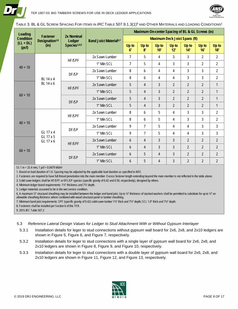
TABLE 3. BL & GL SCREW SPACING FOR ITEMS IN IRC TABLE 507.9.1.3(1)9 AND OTHER MATERIALS AND LOADING CONDITIONS1
Loading Condition (LL + DL)
(psf)
Fastener Designation2,8
(in)
2x Nominal Ledger
Species3,4,5 Band Joist Material6,7
Maximum On-center Spacing of BL & GL Screws (in)
Maximum Deck Joist Spans (ft)
Up to 6'
Up to 8'
Up to 10'
Up to 12'
Up to 14'
Up to 16'
Up to 18'
40 + 10
BL 14 x 4 BL 14 x 6
HF/SPF 2x Sawn Lumber 7 5 4 3 3 2 2
1″ Min SCL 7 5 4 3 3 2 2
DF/SP 2x Sawn Lumber 8 6 4 4 3 3 2
1″ Min SCL 8 6 4 4 3 3 2
60 + 10
HF/SPF 2x Sawn Lumber 5 4 3 2 2 2 1
1″ Min SCL 5 4 3 2 2 2 1
DF/SP 2x Sawn Lumber 5 4 3 2 2 2 1
1″ Min SCL 5 4 3 2 2 2 1
40 + 10
GL 17 x 4 GL 17 x 5 GL 17 x 6
HF/SPF 2x Sawn Lumber 8 6 5 4 3 3 2
1″ Min SCL 8 6 5 4 3 3 2
DF/SP 2x Sawn Lumber 9 7 5 4 4 3 3
1″ Min SCL 9 7 5 4 4 3 3
60 + 10
HF/SPF 2x Sawn Lumber 6 4 3 3 2 2 2
1″ Min SCL 6 4 3 3 2 2 2
DF/SP 2x Sawn Lumber 6 5 4 3 2 2 2
1″ Min SCL 6 5 4 3 2 2 2 SI: 1 in = 25.4 mm, 1 psf = 0.0479 kN/m2 1. Based on load duration of 1.0. Spacing may be adjusted by the applicable load duration as specified in NDS. 2. Fasteners are required to have full thread penetration into the main member. Excess fastener length extending beyond the main member is not reflected in the table above. 3. Solid sawn ledgers shall be HF/SPF or DFL/SP species (specific gravity of 0.42 and 0.50, respectively), designed by others. 4. Minimum ledger board requirements: 1½″ thickness and 7½' depth. 5. Ledger materials assumed to be in the wet service condition. 6. A maximum ½″ structural sheathing may be installed between the ledger and band joist. Up to ½″ thickness of stacked washers shall be permitted to substitute for up to ½″ on allowable sheathing thickness where combined with wood structural panel or lumber sheathing. 7. Minimum band joist requirements: SPF (specific gravity of 0.42) solid-sawn lumber 1½″ thick and 7½″ depth; SCL 1.0″ thick and 7¼″ depth. 8. Fasteners shall be installed per Section 6 of this TER. 9. 2015 IRC Table 507.2
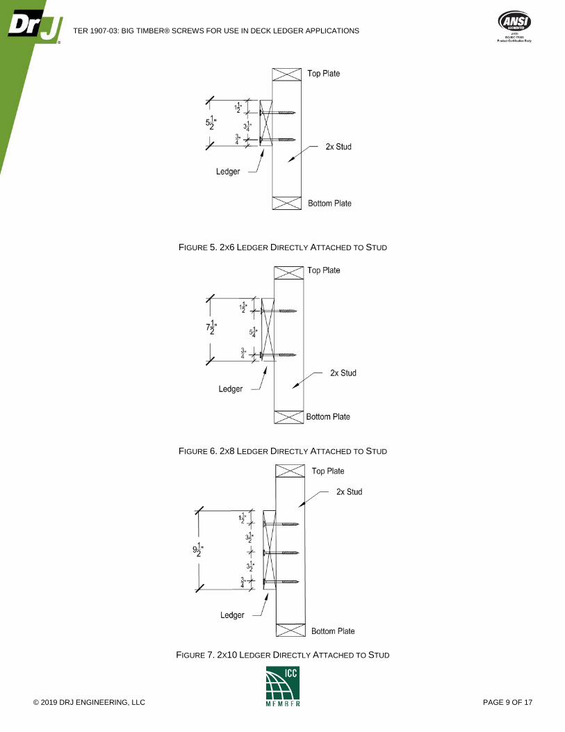
5.3 Reference Lateral Design Values for Ledger to Stud Attachment With or Without Gypsum Interlayer 5.3.1 Installation details for leger to stud connections without gypsum wall board for 2x6, 2x8, and 2x10 ledgers are
shown in Figure 5, Figure 6, and Figure 7, respectively. 5.3.2 Installation details for leger to stud connections with a single layer of gypsum wall board for 2x6, 2x8, and
2x10 ledgers are shown in Figure 8, Figure 9, and Figure 10, respectively. 5.3.3 Installation details for leger to stud connections with a double layer of gypsum wall board for 2x6, 2x8, and
2x10 ledgers are shown in Figure 11, Figure 12, and Figure 13, respectively.
TER 1907-03: BIG TIMBER® SCREWS FOR USE IN DECK LEDGER APPLICATIONS
© 2019 DRJ ENGINEERING, LLC PAGE 9 OF 17
FIGURE 5. 2X6 LEDGER DIRECTLY ATTACHED TO STUD
FIGURE 6. 2X8 LEDGER DIRECTLY ATTACHED TO STUD
FIGURE 7. 2X10 LEDGER DIRECTLY ATTACHED TO STUD

TER 1907-03: BIG TIMBER® SCREWS FOR USE IN DECK LEDGER APPLICATIONS
© 2019 DRJ ENGINEERING, LLC PAGE 10 OF 17
FIGURE 8. 2X6 LEDGER ATTACHED TO STUD THROUGH ONE LAYER OF GWB
FIGURE 9. 2X8 LEDGER ATTACHED TO STUD THROUGH ONE LAYER OF GWB
FIGURE 10. 2X10 LEDGER ATTACHED TO STUD THROUGH ONE LAYER OF GWB

TER 1907-03: BIG TIMBER® SCREWS FOR USE IN DECK LEDGER APPLICATIONS
© 2019 DRJ ENGINEERING, LLC PAGE 11 OF 17
FIGURE 11. 2X6 LEDGER ATTACHED TO STUD THROUGH TWO LAYERS OF GWB
FIGURE 12. 2X8 LEDGER ATTACHED TO STUD THROUGH TWO LAYERS OF GWB
FIGURE 13. 2X10 LEDGER ATTACHED TO STUD THROUGH TWO LAYERS OF GWB

TER 1907-03: BIG TIMBER® SCREWS FOR USE IN DECK LEDGER APPLICATIONS
© 2019 DRJ ENGINEERING, LLC PAGE 12 OF 17
5.4 Reference lateral design values for the ledger to stud connections detailed in Figure 5 through Figure 13 are provided in Table 4 and Table 5. The values in Table 4 and Table 5 apply where the ledger is applied either directly over the studs or with up to two layers of 5/8″ gypsum between the ledger and studs.
TABLE 4. CTX SCREW DESIGN VALUES FOR LEDGER TO STUD ATTACHMENT
Fastener Minimum Fastener Length4
Layers of GWB5 Ledger Size Fasteners Per
Stud6,7
Allowable Load per Stud Connection1,2,3 (lb)
Lumber Species
SPF DF SYP
CTX 14 4
0 2x6 2
245 285 315
1 2x8 140 155 160
5 2 2x10 3 135 140 145
CTX 15 3½
0 2x6 2
340 430 470
1 2x8 205 260 270
5 2 2x10 3 245 255 260 SI: 1 in = 25.4 mm, 1 lb = 4.45 N 1. Allowable loads shall be limited to parallel-to-grain loaded solid sawn main members (minimum 2″ nominal). Wood side members shall be loaded perpendicular to grain. 2. Allowable loads are shown at the wood load duration factor of CD = 1.00. Loads may be increased for load duration as permitted by the building code up to a CD = 1.60. All
adjustment factors shall be applied per NDS. For in-service moisture content greater than 19%, use CM = 0.70. 3. For LRFD values, the reference connection design values shall be adjusted in accordance with the NDS Section 11.3. 4. Required minimum fastener penetration is 6D into the main member, where D is the root minor diameter of the thread. 5. Gypsum board must be attached as required per the building code. 6. Fasteners shall be centered in the stud and spaced as shown in Figure 5 through Figure 13. Minimum end distances shall be per NDS. 7. Additional fasteners prohibited.

TER 1907-03: BIG TIMBER® SCREWS FOR USE IN DECK LEDGER APPLICATIONS
© 2019 DRJ ENGINEERING, LLC PAGE 13 OF 17
TABLE 5. BL & GL SCREW DESIGN VALUES FOR LEDGER TO STUD ATTACHMENT
Fastener Minimum Fastener Length4
Layers of GWB5 Ledger Size Fasteners Per
Stud6,7
Allowable Load per Stud Connection1,2,3 (lb)
Lumber Species
SPF DF SYP
BL 14 4
0 2x6 2
345 440 480
1 2x8 245 270 280
5 2 2x10 3 255 270 275
GL 17 4
0 2x6 2
395 500 575
1 2x8 275 360 390
5 2 2x10 3 335 390 400 SI: 1 in = 25.4 mm, 1 lb = 4.45 N 1. Allowable loads shall be limited to parallel-to-grain loaded solid sawn main members (minimum 2″ nominal). Wood side members shall be loaded perpendicular to grain. 2. Allowable loads are shown at the wood load duration factor of CD = 1.00. Loads may be increased for load duration as permitted by the building code up to a CD = 1.60.
All adjustment factors shall be applied per NDS. For in-service moisture content greater than 19%, use CM = 0.70. 3. For LRFD values, the reference connection design values shall be adjusted in accordance with the NDS Section 11.3. 4. Required minimum fastener penetration is 6D into the main member, where D is the root minor diameter of the thread. 5. Gypsum board must be attached as required per the building code. 6. Fasteners shall be centered in the stud and spaced as shown in Figure 5 through Figure 13. Minimum end distances shall be per NDS. 7. Additional fasteners prohibited.
6 INSTALLATION 6.1 Installation shall comply with the manufacturer’s installation instructions and this TER. In the event of a conflict
between the manufacturer’s installation instructions and this TER, the more restrictive shall govern. 6.2 Lead holes are not required but may be used where lumber is prone to splitting. 6.3 Big Timber® screws shall be installed with the appropriate rotating powered driver. Do not overdrive. 6.4 Install Big Timber® screws such that the threads fully engage the band joist material and the fastener tip extends
beyond the back face of the band joist material when fully seated against the installed ledger. 6.5 For deck ledger connections, stagger the Big Timber® screws from the top to the bottom along the length of the
ledger while maintaining the required edge and end distances. 6.5.1 Figure 4 provides a deck ledger installation detail, including minimum required spacing, end and edge
distances. 6.6 For applications outside the scope of this TER, an engineered design is required.
7 TEST ENGINEERING SUBSTANTIATING DATA 7.1 Properties for Big Timber® CTX Construction Lag Screws are from DrJ TER 1907-01. 7.2 Properties for Big Timber ® BL Log, Timber & Landscape Screws and GL Gray Structural Screws are from DrJ
TER 1907-02. 7.3 ANSI/AWC NDS: National Design Specification (NDS) for Wood Construction. 7.4 Some information contained herein is the result of testing and/or data analysis by other sources which conform to
IBC Section 1703 and relevant professional engineering law. DrJ relies on accurate data from these sources to perform engineering analysis. DrJ has reviewed and found the data provided by other professional sources to be credible.

TER 1907-03: BIG TIMBER® SCREWS FOR USE IN DECK LEDGER APPLICATIONS
© 2019 DRJ ENGINEERING, LLC PAGE 14 OF 17
7.5 Where appropriate, DrJ’s analysis is based on design values that have been codified into law through codes and standards (e.g., IBC, IRC, NDS®, and SDPWS). This includes review of code provisions and any related test data that aids in comparative analysis or provides support for equivalency to an intended end-use application. Where the accuracy of design values provided herein is reliant upon the published properties of commodity materials (e.g., lumber, steel, and concrete), DrJ relies upon the grade mark, stamp, and/or design values provided by raw material suppliers to be accurate and conforming to the mechanical properties defined in the relevant material standard.
8 FINDINGS 8.1 When used and installed in accordance with this TER and the manufacturer’s installation instructions, the
product(s) listed in Section 1.1 are approved for the following: 8.1.1 Big Timber® screws provide an equivalent connection as that required by the IBC Section 1604.8.3 and IRC
Section R507.9. 8.2 IBC Section 104.11 (IRC Section R104.11 and IFC Section 104.9 are similar) states:
104.11 Alternative materials, design and methods of construction and equipment. The provisions of this code are not intended to prevent the installation of any material or to prohibit any design or method of construction not specifically prescribed by this code, provided that any such alternative has been approved. An alternative material, design or method of construction shall be approved where the building official finds that the proposed design is satisfactory and complies with the intent of the provisions of this code, and that the material, method or work offered is, for the purpose intended, not less than the equivalent of that prescribed in this code…Where the alternative material, design or method of construction is not approved, the building official shall respond in writing, stating the reasons the alternative was not approved.
8.3 This product has been evaluated in the context of the codes listed in Section 2 and is compliant with all known state and local building codes. Where there are known variations in state or local codes applicable to this evaluation, they are listed here.
8.3.1 No known variations
9 CONDITIONS OF USE 9.1 Big Timber® screws covered by this TER shall be installed in accordance with this report and the manufacturer's
installation instruction. 9.2 Big Timber® screw spacing shall not exceed those listed in Table 4, Table 5, and Figure 4. 9.3 Use of fasteners in locations exposed to saltwater or saltwater spray is outside the scope of this evaluation report. 9.4 Where required by the building official, also known as the authority having jurisdiction (AHJ) in which the project is
to be constructed, this TER and the installation instructions shall be submitted at the time of permit application. 9.5 Any generally accepted engineering calculations needed to show compliance with this TER shall be submitted to
the AHJ for review and approval. 9.6 Design loads shall be determined in accordance with the building code adopted by the jurisdiction in which the
project is to be constructed and/or by the Building Designer (e.g., owner or registered design professional). 9.7 At a minimum, this product shall be installed per Section 6 of this TER. 9.8 This product is manufactured under a third-party quality control program in accordance with IBC Section 104.4
and 110.4 and IRC Section R104.4 and R109.2. 9.9 The actual design, suitability, and use of this TER, for any particular building, is the responsibility of the owner or
the owner's authorized agent. Therefore, the TER shall be reviewed for code compliance by the building official for acceptance.

TER 1907-03: BIG TIMBER® SCREWS FOR USE IN DECK LEDGER APPLICATIONS
© 2019 DRJ ENGINEERING, LLC PAGE 15 OF 17
9.10 The use of this TER is dependent on the manufacturer’s in-plant QC, the ISO/IEC 17020 third-party quality assurance program and procedures, proper installation per the manufacturer’s instructions, the building official’s inspection, and any other code requirements that may apply to demonstrate and verify compliance with the applicable building code.
10 IDENTIFICATION 10.1 The product(s) listed in Section 1.1 are identified by a label on the board or packaging material bearing the
manufacturer’s name, product name, TER number, and other information to confirm code compliance. 10.2 Additional technical information can be found at bigtimberfasteners.com.
11 REVIEW SCHEDULE 11.1 This TER is subject to periodic review and revision. For the most recent version of this TER, visit
drjcertification.org. 11.2 For information on the current status of this TER, contact DrJ Certification.

TER 1907-03: BIG TIMBER® SCREWS FOR USE IN DECK LEDGER APPLICATIONS
© 2019 DRJ ENGINEERING, LLC PAGE 16 OF 17
APPENDIX A Code Requirements for Ledger Attachments
For guidance on designing the connection of the deck ledger to trusses where a band joist is not used, see SBCA’s Tech Note, Attachment of Residential Deck Ledger to Metal Plate Connected Wood Truss Floor System.
1) IRC Section R507.810 contains the following code requirements (IBC Section 1604.8.3 is similar):
a) Where supported by attachment to an exterior wall, decks shall be positively anchored to the primary structure and designed for both vertical and lateral loads.
i) Attachment shall not be accomplished by the use of toenails or nails subject to withdrawal.
2) IRC Section R507.9.1 details how vertical loads shall be transferred to band joists with ledgers:
a) IRC Section R507.9.1.1
Deck ledgers shall be a minimum 2-inch by 8-inch (51 mm by 203 mm) nominal, pressure-preservative-treated Southern pine, incised pressure-preservative-treated hem-fir, or approved, naturally durable, No. 2 grade or better lumber…
b) IRC Section R507.9.1.2
Band joists supporting a ledger shall be a minimum 2-inch-nominal (51 mm), spruce-pine-fir or better lumber or a minimum 1-inch by 9½-inch (25 mm x 241 mm) dimensional, Douglas fir or better, laminated veneer lumber. Band joists shall bear fully on the primary structure capable of supporting all required loads.
c) IRC Section R507.9.1.311 Fasteners used in deck ledger connections in accordance with Table R507.9.1.3(1) shall be hot-dipped galvanized or stainless steel and shall be installed in accordance with Table R507.9.1.3(2) and Figures R507.9.1.3(1) and R507.9.1.3(2).
d) Tables R507.9.1.3(1) and R507.9.1.3(2)12 cover the placement of lag screws or bolts in deck ledgers:
The tip of the lag screw shall fully extend beyond the inside face of the band joist.
10 2012 IRC Section R507.1, 2015 IRC Section R507.1 11 2012 IRC Section R507.2, 2015 IRC Section R507.2 12 2012 IRC Section R507.2.1, 2015 IRC Section R507.2.1
FIGURE 14. PLACEMENT OF LAG SCREWS AND BOLTS IN BAND JOISTS, IRC FIGURE R507.9.1.3(2)
TER 1907-03: BIG TIMBER® SCREWS FOR USE IN DECK LEDGER APPLICATIONS
© 2019 DRJ ENGINEERING, LLC PAGE 17 OF 17
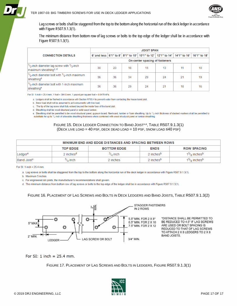
Lag screws or bolts shall be staggered from the top to the bottom along the horizontal run of the deck ledger in accordance with Figure R507.9.1.3(1).
The minimum distance from bottom row of lag screws or bolts to the top edge of the ledger shall be in accordance with Figure R507.9.1.3(1).
FIGURE 15. DECK LEDGER CONNECTION TO BAND JOISTA,B, TABLE R507.9.1.3(1)
(DECK LIVE LOAD = 40 PSF, DECK DEAD LOAD = 10 PSF, SNOW LOAD ≤40 PSF)
FIGURE 16. PLACEMENT OF LAG SCREWS AND BOLTS IN DECK LEDGERS AND BAND JOISTS, TABLE R507.9.1.3(2)
FIGURE 17. PLACEMENT OF LAG SCREWS AND BOLTS IN LEDGERS, FIGURE R507.9.1.3(1)