technical documentation page - lehigh university
TRANSCRIPT

/ ;>''
L Report No. 2. Governm~nr Ac:cession Na.
4. Title ond Subtitle·
Composite Compression Bottom Flange for Steel Box Girders, Executive Summary
Technical ~eport Documentation Page
3. Recipient's Cotolog No.
'5. Report Dote
January, 1986 6. Performing Orgoni zotion Code
1--::--~~--------------------------~ B. Performint.Orgqniution Report No. 7. A .. tho,lsl Fritz t;ng1neering Laborator
B. T. Yen, T. Huang, D. Wang, C. K. Chuang, J. H. Daniel Report No. 489.3A
9. Performing Orgoni&otion Nonoe ond Addreu
Fritz Engineering Laboratory #13 Lehigh University Bethlehem, PA 18015
10. Wort. Unit No. (TRAIS)
11. Controct or Gront No.
DTFH61-83-C-00084 13. Type of Report ond Period Co ... red
~~--------------------~---------------------------------1 12. Sponsoring Agency Nome ond Address U.S. Department of Transportation Federal Highway Administration 400 Seventh Street, SW Washington, DC 20590
15. Supplementary Notes
Final Report September 1983-November 1985
14. Sponsoring Agency Code
FHWA Contract Manager is Craig A. Ballinger, HNR-10
16. All'stroct
This report is the executive sunnnary of the final report of a study on the use of composite steel-concrete compression flanges in the negative moment regions of continuous steel box girder bridges. Preliminary analyses of several bridge designs reveal the possibility of reducing or eliminating haunches, with significant ramifications on efficiency of design as well as on economy of fabrication and erection. Tests of small panel and box girder specimens show that with the use of concrete, the controlling mode of failure changes from the overall buckling of the bottom flange steel plate panel to local buckling between transverse anchor lines. Tte concrete slab shares in carrying compression force in the flange. Design guidelines are presented to insure the development of full yield strength of the steel plate and the full composite action of the materials. Proposed modifications to the AASHTO Specifications are included. Separately issued is the main report, of the same title and date, Fritz Engineering Laboratory Report 489.3, Government Report No.
,F.RiiZ E:NGINEER1NG ~ORATORY U8RAfW
17. Key Words
-Box Girder, Composite Action, Local Buckling, Steel, Concrete, Continuous Spans, Testing, Design, Specifications
lB. Distribution Statement
No restrictions. This document is available to the public through the National Technical Information Service, Springfield, Virginia 22161 ~
~~~~~~--~--~~~~~~~~--~~~~~~~--~~ 19. Security Clouil. (of this report) 20. Security Clossif. (of this poge) 21. No. of Pogu 22. Price
Unclassified Unclassified 25 VJ ~F-o-rm __ D_O_T __ F_1_7_00-.-7-!-B--7-2l---------L--------------------------L---------~----------~ ~
Reproduction of completed page outhori zed ~

INTRODUCTION
Steel box gir:dar:s ar:a frequently used for medium and long span
continuous bridge superstructures. Typically, the. highest longitudinal
bending moment in the structure occurs ove.r the piars. In. the.se negative
moment regions, it is often nacessar:y to strengthen th.e bottom (compressive)
flange by increased plata thickness or longitudinal stiffaners, or both.
For long span bridges, it is also oftan nacassary to increase the structural
depth at the pie~s, resulting in a haunched profile.
Each of the special design features mentioned above increases the
complexity and decreases the efficiency of the structure. The costs for
material, fabrication and erection are increased. Furthermore, the
increased complexity of the structure also renders it more difficult to
predict its behavior under load. New design approaches to improve the
structural efficiency in the negative moment regions are. urgently needed.
One such new approach involves the use of steel-concrete composite
compression flanges in these regions. This is the topic of study for the
research project reported herein.
PROBLEMS STUDIED
The objective of this study was to examine the possibility of using
composite compressive bottom flanges in continuous steel box girders, with
the goal of improving the structural efficiency of the flange system and
eliminating the haunches.
The first task in this research undertaking was a feasibility study
on the uses of fully composite steel-concrete compression flanges. Design
plans of three continuous steel box girder bridges, with main span lengths
up to 590 ft, were provided by the Federal Highway Administration. Figure 1
shows the distinct characteristics of the bridges. Alternate designs for
these bridges were developed incorporating the use of fully composite
compression flanges over the piers. Comparisons w~th the original designs
were made on the basis of both strength and estimated cost. A large number
of parameters were examined, including the thickness of steel bottom flange
and web plates, the thickness and length of the concrete slab, the strength
1

and density of concrete., the main spa,n length, the span ratio, the midspan
structural depth, the haunch ratio, and the procedure of fabrication and
erection. Results of this study clearly established the feasibility of
using composite compression flanges to eliminate the haunches completely.
The development of full composite strength of the steel-concrete
compressive. flange, corresponding to yielding of th.e steel plate and
crushing of the concrP-te slab.depends upon the anchorage between the two
materials and the bearing of the concrete slab at its ends. The material
properties, the relative thicknesses, and the amount of anchorage are
factors which influence the behavior of the composite flange. An analytical
study on the strength of composite flange panels was made, utilizing exis
ting solutions of buckling strength of steel plates. Special attention was
given to the local behavior of the steel plate betwe.en two transverse rows
of anchors, or among four anchors (see figs. 2 and 3). The effects of
concrete shrinkage and creep, the bending of steel plate under the weight
of fresh concrete, and the transmission of loads at the end of the panel
were studied in detail. The pullout strength of anchors was also examined.
TEST PROGRAM
Four small specimens of composite compression panels were tested.
Each specimen had a 62 by 50 by 3/8 in steel plate, combined with a 60 by
48 by 3 in concrete slab (fig. 4). The major factors examined in this
experimental task included the spacing between anchors, the bearing condition
at the ends of the concrete slabs, the distance between longitudinal supports
simulating web plates, and the presence of out-of-plane loading. Table 1
gives the dimensions, material properties, and loading arrangements of the
four panel specimens. The specimens were tested under an in-plane
compressive load, either on the steel plate, or at the centroid of the
composite cross section, as illustrated in figure 5. Table 2 summarizes
the test results. Figure 6 shows a specimen in the test machine.
2

A 38 ft 3 in long box girder specimen, w:ith a 3 by 4 ft cross
section and a 3 in thick concre.te slab, was tested in negative bending
in four different arrangement of loading·and supporting locations.
Figures 7 and 8 show the dimension and details of the specimen.
Figure 9 shows the various test arrangement and the respective ultimate
bending moment diagrams. Parameters varied in these. box girder bending
tests were the strength of concrete, the bearing condition at the ends
of the concrete slab (against the diaphragms), the anchoring at the
ends of the concrete slab, and the moment gradient in the test panel.
The combination of parameters for each test is summarized in table 3.
Table 4 provides the predicted and observed moment strength for each test.
Figure 10 shows the specimen in the test machine.
Based on the results of the analytical and experimental studies,
practical design rules were developed for the composite compression
flanges in continuous box girders. Appropriate specification provisions
are proposed for consideration by the American Association of State
Highway and Transportation Officials.
SUMMARY AND RECOMMENDATIONS
1. Summary of Findings
From the analysis of sample bridges, the testing of composite panels
and box girder segments, and the evaluation of results, the following
items of summary can be made:
(1) It is possible to reduce or eliminate haunches in the negative moment regions of the continuous steel box girders by using composite compressive bottom flanges in these areas. Adding of composite concrete slab is equivalent to having a thicker bottom flange plate, thus enabling the reduction or elimination of haunches.
(2) The required thickness and length of concrete slab ove.r the bottom flange steel plate are influenced by the span length, by the adopted box girder depth at the piers and at the center of span, and by the chosen thickness of the bottom flange steel plate.
3

(_3) Because. constant del'th box girder bridges are simpler foJ; fabrication and erection, <;l.lternative. design('~ of two sample bridges were made assuming constant depth throughout the entire length of each bridge. For a three span bridge with a maximum span of 590 ft and a depth of 27 ft at the piers, one of the alternative. des:tgns permitted a uniform depth of 16 ft with a concrete slab 18 in thick at the piers and tapering to zero at about 1/5 of the maximum span. For a five. span bridge with a central span length of 450 ft and a maximum depth of 21 ft 4 in over two piers, a uniform depth box girder 10 ft 4 in deep with 18 in maximum thickness of concrete slab was among the possible alternative designs. The yield strength of the steel was 50 ksi and the concrete strength wa.s assume.d 4000 psi in these examples.
(_4) Theoretically, for a chosen concrete slab thickness in a box girder, higher strength of concrete. results in lower compressive stresses in the composite compressive bottom flange. Bearing of concrete slabs on box girder diaphragms, however, is essential to the development of the full strength of the composite compression flange. Results from testing box girder segments showed that the higher concrete strength was not fully utilized if the concrete slab was not in directed bearing.
(5) The procedures of construction and erection can have very strong influence on the utilization of strength of the composite compressive bottom flange. Cast-in-place concrete slab requires sufficient strength of bare bottom flange steel plate to resist in-plane compressive stresses and out-of-plane plate bending stresses due to wet concrete. Precast concrete planks can be attached before erection or attached on site to form the composite slab; the former provides strong box girder segments for transportation and erection and both procedures require grouting. The selection of a procedure obviously depends upon the geometry and location of the bridge as well as the capability of the fabrication and construction team.
(6) Shrinkage and creep may result in a gap between a concrete slab and the transverse member (diaphragm or stiffener) at the end of the slab. Evaluation of the alternative design of one sample bridge and the design of one practical thin composite panel showed that shrinkage and creep did not govern.
(7) The use of lightweight concrete had very little effect on the total weight of the sample bridge. The lower modulus of elasticity of the light-weight concrete resulted in smaller cross sectioned area of equivalent steel flange plate and correspondingly higher compressive stresses in the composite flange.
4

(8) By assuming wide ranges of unit costs for fa,bric.ated steel and concrete, it wa,s found that the total cost of the alternative design far each of the two sample bridges was lower than the original design. Therefore,· it is analytically possible and economically feasible to eliminate haunches o.r to strengthen the negative moment region of continuous box girders by using composite compression flanges.
(9) There is no readily available closed-form analytical solution for steel plates· subjected to in-plane compression and out-ofplane bending simultaneously. The evaluation of strength of the bottom flange steel plate during erection and construction is therefore quite complicated and approximate. Caution must be taken in this regard.
(10) The strength of composite compression flange depends on the end conditions of the concrete slab. The slab may or may not be in bearing with the diaphragms or transverse stiffeners at the ends. The corresponding loading conditions for the composite compression flange are either concentric or eccentric loads, respectively.
(11) The first row of concrete. slab anchors on the steel flange plate may be placed at or near the ends of the slab, or at a short distance away from the end. In the latter case, if the concrete slab is not in bearing, the steel plate alone carries the total compressive flange force in that region.
(12) Tests were conducted on box girder segments with the concrete slab not in bearing and not anchored to the steel plate near the ends of the slab. Failures were by local buckling of the steel flange plate between the first row of anchors and the end of the slab.
(13) Tests were conducted on composite flange panels with concrete slab not in bearing but with equivalent anchors at the ends of the slab. Failure was by cracking of concrete slab. The composite compression panels were subjected to eccentric load causing bending of the composite panel toward the concrete slab.
(14) For composite compression flange panels with concrete slabs in bearing, the strength of the flange panel depends on the spacing of concrete slab anchors. Small spacing between the transverse rows of anchors prevents local buckling of steel plate and permits development of full strength of the composite flange panel.
5

(15) The test specimens. had 48 ;Ln ~ide panels.~ith 3/8 in thick flange plates and 3 in thick concre.te s.labs. The anchor studs were 2 by 1/2 in arranged in different longitudinal spacing (pitch} and transverse distances (gage length). Failure of compression flanges was predominantly by local buckling between two rows of anchor studs. In two cases the ultimate strength of yielding the steel plate plus crushing the concrete slab was achieved. The failure modes were consistent with the predicted results.
(16) The strength of composite compressive flanges as governed by local buckling can be predicted approximately. The steel plate between two rows of anchors is considered simply supported at the boundaries. The lateral force of the concrete slab weight on the steel plate is not considered applicable between two rows of anchors because the concrete does not buckle with the steel plate. In all cases of test, the strength from testing was reasonably above the predicted values.
(17) The full strength of composite compression flange panel is dependent upon the strength of the c.onc.rete. and the thickness of the slab. For a chosen concrete slab thickness, higher strength concrete contributes to a bigger transformed steel bottom flange and a higher cr:oss sectional moment of inertia of the box girder. The resulting stresses in the composite flange is lower.
(18) The relative thickness of the concrete slab to the steel plate was about 8 and 9 for the test specimens and an alternatively designed bottom flange of a sample bridge respectively. A thickness ratio of 8 to 12 appears to be adequate.
(19) There was little transfer of forces between steel plate and concrete in the test specimens. The studs for anchoring the concrete slab appeared to be also sufficient for shear between the steel plate and the concrete slab. The approximately uniform distribution of stresses in the bottom flange steel plates confirmed the effectiveness of the anchored concrete slab in strengthening the steel plate.
(20) No fatigue test was planned or conducted. The anticipated low shear stresses at the anchors were not expected to cause any problem from fatigue.
6
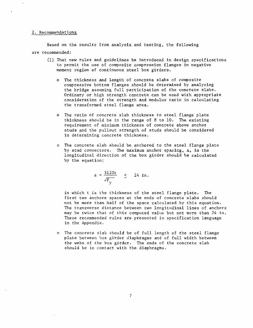
2. Recommendation~
Based on the results from analyst~ and testing, the follow:ing
are reconnnende.d;
(1) That ne.w rules and guidel:ines be introduced in des:ign specifications to permit the. use. of composite compression flanges in negative moment region of continuous steel box girders.
o The thickness and length of conc-x:ete slabs of composite compressive bottom flanges should be. determined by analyzing the bridge assuming full participation of the concrete slabs. Ordinary or high strength concre.te. can be used with appropriate consideration of the strength and modulus ratio in calculating the transformed steel flange. area.
o The ratio of concrete. slab thickness to steel flange plate thickness should be in the range of 8 to 10. The existing requirement of minimum thickness of concrete above anchor studs and the pullout strength of studs should be considered in determining concrete thickness.
o The concrete slab should be anchored to the steel flange plate by stud connectors. The maximum anchor spacing, a, in the longitudinal direction of the box girder should be calculated by the equation:
a = 5120t
~ y
< 24 in.
in which t is the thickness of the steel flange plate. The first two anchore spaces at the ends of concrete slabs should not be more than half of the space calculated by this equation. The transverse distance between two longitudinal lines of anchors may be twice that of this computed value but not more than 24 in. These reconnnended rules are presented in specification language in the Appendix.
o The concrete slab should be of full length of the steel flange plate between box girder diaphragms and of full width between the webs of the box girder. The ends of the concrete slab should be in contact with the diaphragms.
7

(2) That additional research be conducted to examine further the behavior of composite compression flanges and to explore new applications.
o Field measurements of stresses and displacements are needed of a bridge which has a composite compression flange or has a compressive bottom flange strengthened by a concrete slab.
o Investigation is suggested on the possibility and advantages of applying concrete slabs to horizontally curved steel box girders.
8
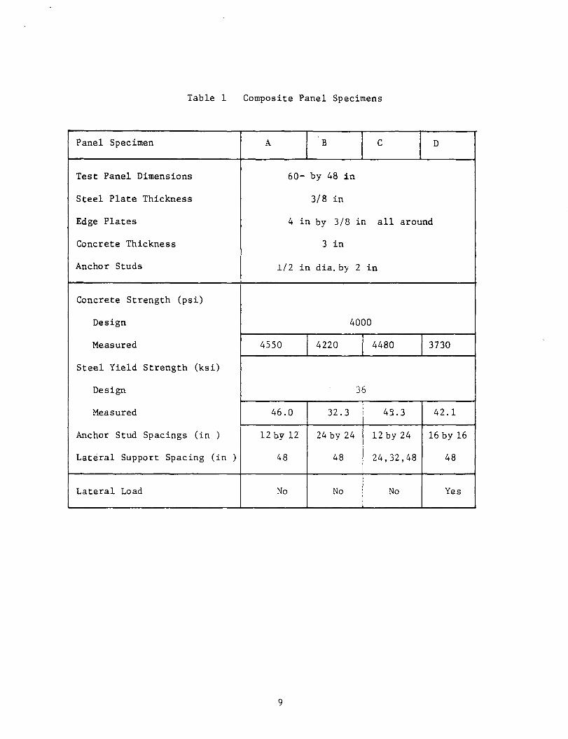
Table 1 Composite Panel Specimens
Panel Specimen A B c D
Test Panel Dimensions 60- by 48 in
Steel Plate Thickness 3/8 in
Edge Plates 4 in by 3/8 in all around
Concrete Thickness 3 in
Anchor Studs 1/2 in dia. by 2 in
Concrete Strength (psi)
Design 4000
Measured 4550 4220 4480 3730
Steel Yield Strength (ksi)
Design 36
Measured 46.0 32.3 45.3 42.1
Anchor Stud Spacings (in ) 12 b.y lZ 24 by 24 12 by 24 16 by 16
Lateral Support Spacing (in ) 48 48 24,32,48 48
Lateral Load No No No Yes
9

...... 0
Table 2 Limit State Loads of Composite Panels
Test Al A2 Bl B2 Cl-1
steel steel steel steel steel
Load & & on cone. cone.
Lat. Sup. Spacing (in.) 48 48 48 48 48
Initial Yielding(l) ( 2) 830k -- 830 -- 830
k Cracking of Concrete 200 -- 200 -- 200
Full- Strength (3) -- 1160 -- 1160 --
Buckling between two (4) 520( 5) 1040 180(5 ) 360 520( 5)
rows of anchors
Buckling between 1100 2200 290 580 540 four studs
Notes: (l) First yield of steel plate in composite panel k
(2) Yielding of steel plate alone without concrete slab, 675
Cl-2
steel
32
830
200
--
600( 5)
1450
Cl-3 C2 D
steel steel steel & &
cone. cone.
24 48 48
830 -- --
200 -- --
-- 1160 1160
720( 5) 1040 640
2200 1080 1300
(3) Strength of direct compression of composite panel, yielding of steel plate (without buckling) and crushing of concrete.
(4)
(5)
k Buckling of steel plate alone without concrete slab 290
Assuming steel plate alone carries load

Table 3 Box Girder Specimen Design and Material Properties
1 2 3 4 5 6
Box Segment I
2-3 l 3-4 4-5 5-6 and 1-2
I
Steel Yield Strength (ksi) I I
1 in plate (top flange) I 34.9
3/8 in plate (all other) I 42.7
Concrete Strength (psi) I 5580 3820 3820 4100
I
Bottom Flange Design: I I Panel Dimension (in) , I 72 by 48 109 1/z by48
Steel Plate Thickness (in) ! 3/8
Concrete Thickness (in) I 3 I
Anchor Spacing (in) i 16 X 16 i
Concrete Slab In Bearing I I No Yes No No I I
11

Table 4 Summary of Box Girder Spec.imen Failure Tests
2 3 4
Test 3 4 1
Test Segment 2-3 2-3 3-4 3-4
Concrete Slab Not bearing Bearing Not Bearing
Failure Location 2 2-3 3-4 4
Predicted Failure
Moment (k-ft) 2290 2400 2220 2290
Observed Failure
Moment (k-ft) 2580 2840 3415 2420
Failure Mode Buckling of Steel Plate
(1) (2) (2) I (1)
Note:
(1) Buckling upward between diaphragm and first row of studs
(2) Buckling downward between two rows of studs
12
5
2
4-5
Not Bearing
5
2290
3010
I (1)
l z.. f
j. s

375' .. I- 590' J~ 375 I • I ,. 53 I .., 12 1 -6 11
Earies I 27' design 16' uniform
1- 20 I ·I (a) West Seattle Bridge
310' 400' 450' 400' ·~
310' . I I~ r-50' --I 3Z I ~j
~ries\ 7 1-\,;.) 16' 21 '-4' lt. design
10' -4 11 uniform j-varies.,.j
(b) Columbia River Birdge
, .. 200' b 1-- 420' ·I 200' ·I 1· ~~=~ ·1
I
I I
~2 I -6 II I 12'-6'I_ 0 v ~ y
(c) Tennessee Tombigbee Bridge 5'-6 11
Figure 1 Characteristics of Three Bridge Structures (Schematic)

~ : 0 0 ~ 0 0
I I I I
0 0 ~ 9 0 0
I I I I
0 0 9 ~ 0 0
I I
p _ o::!!:::~ =='===!:'===r~~~T~~:=::==T ====!:=t===l:tl _ p
a
Figure 2 Local Buckling Between Anchor Rows
14

q -------a------·
y z
Model I · no rotation on edges
q------ a
/
/
y z
Model IT: rotation free oo edges
Figure 3 Model of Steel Plate Buckling Between Anchor Points
15

50
t------- 62 ------+
.. ~ . ,;
,.. \ ' - ,-) -
~-----60 ____ ______,.
3/s Je. all around· A.· . .. 4.: ..
48
13
Number & Spacing of Studs
Vary with Specimens
Unit: inches
Figure 4 Small Panel Specimens
16

MACHINE HEAD
6.
b
~
•
•
....
•
•
'
PLATFORM (a)
MACHINE HEAD
. 4
4
...
6.
b
•
6•
4
PLATFORM (b)
Figure ') Loading Conditions of Panel Specimen
17

Figur e 6 Panel Spe c imen in Test ~b · h ine
I '

l'-l/2"
1' 1- 1-
Stiffener 5" x 3/8"
9'-1.5" 6'
Elevation 38'-3"
Diaphragm
6' I· 6'
Stiffener 511
X 3/8 11
I I 9'-1.5" 1' ·I ·I
17 @ 2'-0" = 34'-o" ---4--~----------------------------~~~~~----~--~------------------------------~~~l'-l 1/2"
5" x 3/8" Transverse Stiffener (Typ)
Girder Web IL
Section A-A
Figure 7 Box Girder Specimen
x 1 11 TransStiffener
(Ty ,)
Longitudinal Bottom Flange Stiffener
ST6 x 15.9

Web Plate 36" X 5/8"
Long. Stiffene 5" X 3/8"
ST6 x 15.9 End Segments Only
r
I
72"
Top Flange Plate 72" x 1"
Transverse Stiffener 5" X 3/8"
CXl
\C) C""l C""l
r-... C""l
c= ~
:·•: ~· ··•.-:·::: .•·-: ......... :. : ': ·: ~·.·.:· .. ·:A ~
_.l:. Bottom Flange Plate 50" x 3/ "
48"
(a) Typical Cross Section
3" X 3/8"
I'" _ ... ·I 24"
(b) Tvpi~~l Diaphragm Section
-I
Transverse Stiffeners 5" x 1"
Figure 8 Box Girder Specimen Cross Section
20

1 2 3 4 5 6
, .. 9 1 -1 1/2" I· 61 6 I 6 I 9 1 -1 1/2" ·I
Test 1
2420 k-ft
3010
Test 2
-M
Test 3 2580
-M
(3980)
Test 4
'\, 4 I -4 II '\, 3 I I ·I ·I
Figure 9 Support Locations and Mom~nt Diagrams of Box Girder Specimen Tests
21

figure 10 Box Girder Sp ec imen in Tes t ~achine
•))
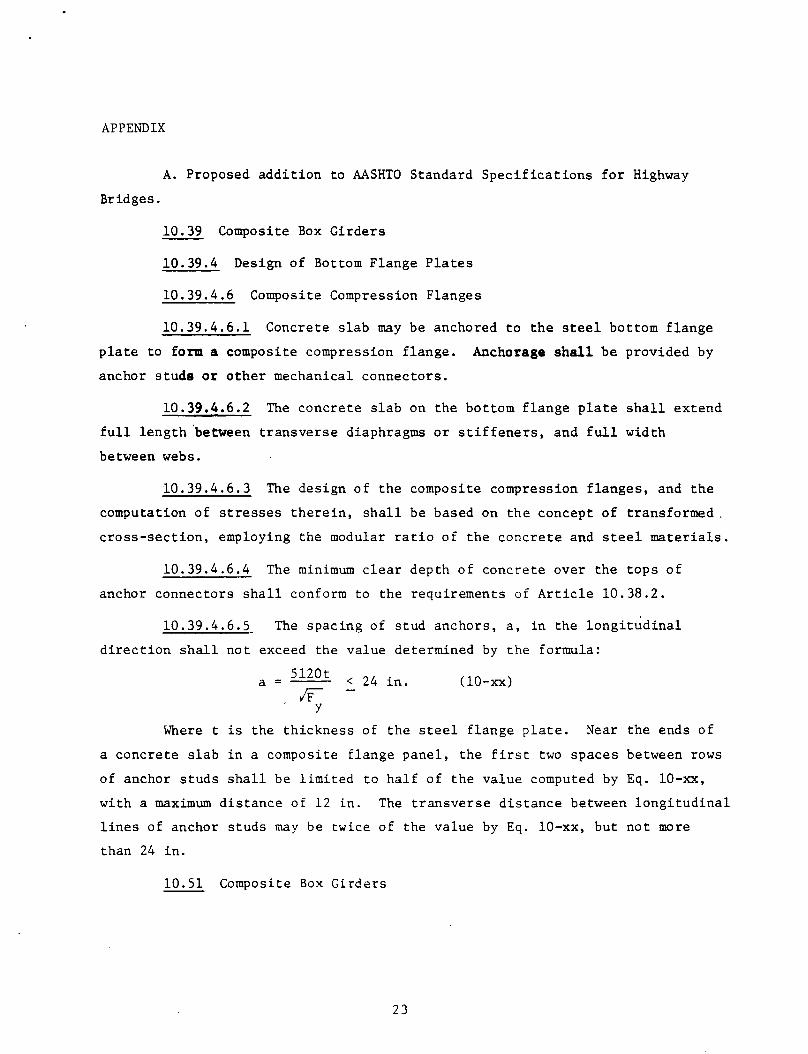
APPENDIX
A. Proposed addition to AASHTO Standard Specifications for Highway
Bridges.
10.39 Composite Box Girders
10.39.4 Design of Bottom Flange Plates
10.39.4.6 Composite Compression Flanges
10.39.4.6.1 Concrete slab may be anchored to the steel bottom flange
plate to form a composite compression flange. Anchorage shall be provided by
anchor studs or other mechanical connectors.
10.39.4.6.2 The concrete slab on the bottom flange plate shall extend
full length 'between transverse diaphragms or stiffeners, and full width
between webs.
10.39.4.6.3 The design of the composite compression flanges, and the
computation of stresses therein, shall be based on the concept of transformed .
cross-section, employing the modular ratio of the concrete and steel materials.
10.39.4.6.4 The minimum clear depth of concrete over the tops of
anchor connectors shall conform to the requirements of Article 10.38.2.
10.39.4.6.5 The spacing of stud anchors, a, in the longitudinal
direction shall not exceed the value determined by the formula:
a = 5120t < 24 in. IF
y
(10-xx)
Where t is the thickness of the steel flange plate. Near the ends of
a concrete slab in a composite flange panel, the first two spaces between rows
of anchor studs shall be limited to half of the value computed by Eq. 10-xx,
with a maximum distance of 12 in. The transverse distance between longitudinal
lines of anchor studs may be twice of the value by Eq. 10-xx, but not more
than 24 in.
10.51 Composite Box Girders
23

10.51.5 Compression Flanges
10.51.5.6 Composite Compressive Bottom Flanges
The conditions and provision of Article 10.39.4.6 for the allowable
stress design method are also applicable here for the load factor design
method.
B. Commentary on Proposed Article 10.39.4.6 and 10.51.5
10.39.4.6.1 Concrete slab anchored to the steel bottom flange plate
can act compositely with the steel plate to form a composite compression
flange. The strength of the compression flange is increased from that of
overall buckling of the steel plate to that of local buckling of the plate
between rows of anchors.
10.39.4.6.2 If the concrete slab is not in bearing at its ends, the
composite compression flange is subjected to eccentrical load with respect to
its centroidal plane. Full length slab in bearing permits direct transmittal
of forces into the slab and its direct participation in resisting compression.
Full width slab is also specified so as to provide restraint along the flange
to-web junction. The thickness of the concrete slab is to be determined
through the analysis of bridge bending moments and compressive stresses in
the steel flange plate.
10.39.4.6.3 The analysis and design of the box girder with composite
bottom flange should be made on the basis of transformed cross section where
the two materials are converted into one by means of modular ratios as
specified in Article 10.38.1.2 and 10.38.1.3.
Dependent upon the fabrication and erection procedures, the critical
stress condition in the composite box section may occur at a stage before
the completion of the bridge construction. Appropriate considerations must
be given to these early stage conditions, such as: (1) bare steel plate
bottom flange supporting the weight of fresh concrete, (2) bare steel plate
bottom flange supporting partial bridge weight and fresh concrete in
segmental construction.
24

10.39.4.6.4 A minimum thickness of concrete is specified, similar
to that for composite I-beams, in order to provide anchorage between the
concrete and steel.
10.39.4.6.5 The limit for stud anchors spacing is derived on the
basis that local buckling between two transverse rows of stud anchors will
not occur prior to yiedling of the steel plate. The maximum spacing of 24
in. is imposed because no distance of more than 24 in. existed in test
specimens of the study leading to this rule. An end space of half the value
from Eq. lO.xx is specified to cover uncertainties such as the bearing of
concrete slab and the condition of splice plates in this area for field
connections. In all cases, direct bearing of the slab at its ends is
recommended.
10.51.5 See commentary for 10.39.4.6.
25