technical document dear john, mission valley high rise
TRANSCRIPT
March 26, 2021
Mr. John PrinceDelane Engineering- OwnerSan Diego Mission Valley High Rise Hotel4909 Murphy Canyon Rd. #330San Diego, CA 92123
SUBJECT: San Diego Mission Valley High Rise Hotel Water System AnalysesTechnical Document
Dear John,
This technical document serves as the Water System Analyses for the San DiegoMission Valley High Rise Hotel onsite water systems Project. The purpose of this studyis to verify potable and fire water demand for the Project and to analyze onsite systemsfor adequate pressure and flow to every fixture at all times. This will ensure that Health,Safety and Noise considerations will be taken into account.
Project Background
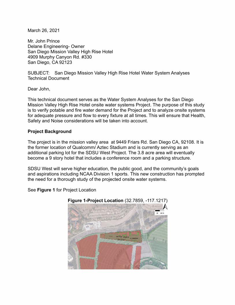
The project is in the mission valley area at 9449 Friars Rd. San Diego CA, 92108. It isthe former location of Qualcomm/ Aztec Stadium and is currently serving as anadditional parking lot for the SDSU West Project. The 3.8 acre area will eventuallybecome a 9 story hotel that includes a conference room and a parking structure.
SDSU West will serve higher education, the public good, and the community’s goalsand aspirations including NCAA Division 1 sports. This new construction has promptedthe need for a thorough study of the projected onsite water systems.
See Figure 1 for Project Location
Figure 1-Project Location (32.7859, -117.1217)

Existing Water Service
The Project is located within the SDSU West master plan. Potable service for the area isprovided by the Lake Murray Treatment Plant, located along Lake Murray Road to theNorth East of the Project location. The anticipated hydraulic grade line of the Project is81 feet, as provided by the grading plans and boring logs provided to Centaur Solutions.
The campus will have separate potable and fire systems.
Figure 2 Existing Water Service (POC TBD)
Potable Water Service
The onsite potable water system use includes drinking, cooking, toilet flushing, (poolfilling), and bathroom services. Existing public service lines along Friars Rd. and Road(b) currently provide service to the entire SDSU West site along with backflowprevention. A separate 2” meter with backflow protection will be installed along Road(a), to supply the hotel, conference room, and parking structure demand.
See Figure 2 for existing potable layouts surrounding the Project.
Design Criteria
Design criteria for the potable water systems are per the City’s Design Guidelines, aspresented in Table 1.
Table 1- Design CriteriaParameter Potable Water Criteria
Fire Flow Min 1500 gpm (need to size)

Minimum Static Pressure 65 psi
Minimum Pressure, MDD + Fire 20 psi
Minimum Pressure, Peak Hour 40 psi
Maximum Pressure Drop 25 psi
Maximum Velocity, MDD + Fire 15 fps
Maximum Velocity, Peak Hour 8 fps
Water Demand
Potable Water Demand
The use of fixture units to project peak water demand can be performed on a building tobuilding basis. This methodology, described in the California Plumbing Code (CPC),utilizes the total number of plumbing fixtures (hot and cold) to determine the peak flowto a building. The relationship between fixture units and peak flow per the CPC isprovided in (Appendix A). This method is used to size the meter and laterals into asingle building. Proper procedure for this methodology is to sum the total amount offixtures for the building to determine the total peak flow. (See Appendix A).
Based on the calculations and appendix the hotel will require a 2” meter and a 2.5”supply line to supply a peak demand of 468 gpm. Since the hotel is being sized by CPCfixture methodology it is not warranted to calculate future demand unless the building isenlarged.
Fire Water Demand
The hotel will require its own separate fire flow based on building square footage andconstruction type per the California Fire Code (CFC) requirements. (See Appendix B.)The system will be connected with backflow preventers from connections to the existingCity of San Diego public system. Done by April 6th, 2021
Initial Assumptions
1) The 1st level floor is at 0 feet in height and approx 81 feet in elevation (fromboring log initial bore height).
2) The 1st level ceiling is 20 feet in height above the 1st level floor and approx 101feet in elevation.
3) The 2nd level floor and 1st level ceiling are equal in height and elevation.4) Each subsequent level is 10 feet of height above the prior which reaches the roof
at 9th level ceiling.

5) An additional 3 feet is assumed to be the last fixture height on the roof and will beused as the governing fixture (hose bib).
6) Levels 2-9 are to be 13,000 square feet and will contain 330 square foot rooms(Standard size off google) and therefore contain 40 rooms per level. For a total of320 rooms.
7) Each room shall contain one wash closet, one lavatory, and one bath/showercombination.
8) Each level (1-9) shall contain one Mop Basin or Service Sink9) Level 1 shall contain a 2000 square foot lobby area with 8 wash closets, 6
lavatories, and 4 urinals10)Level 1 shall contain a fitness area and Locker containing 6 shower heads and 4
lavatories11)A Mechanical Equipment Room (MER) shall be installed on the 4th level to have
approximately 200gpm pumped (See Appendix B for recommended product) tolevels 5 through 9.
12)The total fixture height shall be 103 feet in height and 184 feet in elevation for thegoverning fixture
Recommendations
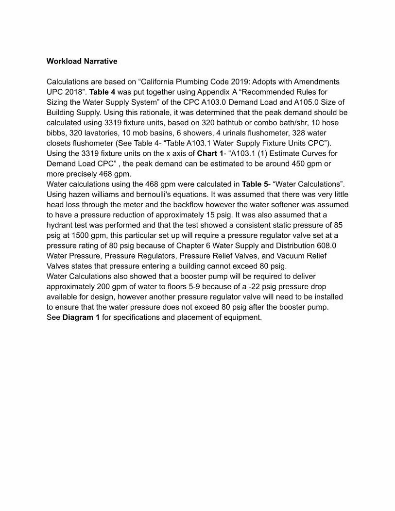
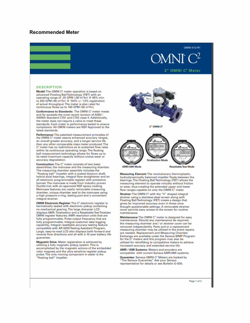
1) Centaur Solutions recommends purchasing an Omni C2 2” meter, a Watts Series009 reduced pressure assembly backflow prevention device, 2 Watts LF223 HighCapacity Water Pressure regulator valves and a Bell and Gossett Series e-80In-Line Centrifugal Pump pump (See Appendix C for specification sheets).
2) A 2 ½” main pipe will serve a peak demand of 468 gpm based on CPC fixturesizing (See Appendix A)
3) Fire Demand Recommendations by April 6th, 2021 (See Appendix B)4) Fire Demand Recommendations by April 6th, 2021 (See Appendix B)
If there is any questions or comments, please feel free to contact Centaur Solutions at619-706-8484
Sincerely,
Centaur SolutionsCorey Hutchison, E.I.T.

Appendix A
Water Calculations and Rationale
Workload Narrative
Calculations are based on “California Plumbing Code 2019: Adopts with AmendmentsUPC 2018”. Table 4 was put together using Appendix A “Recommended Rules forSizing the Water Supply System” of the CPC A103.0 Demand Load and A105.0 Size ofBuilding Supply. Using this rationale, it was determined that the peak demand should becalculated using 3319 fixture units, based on 320 bathtub or combo bath/shr, 10 hosebibbs, 320 lavatories, 10 mob basins, 6 showers, 4 urinals flushometer, 328 waterclosets flushometer (See Table 4- “Table A103.1 Water Supply Fixture Units CPC”).Using the 3319 fixture units on the x axis of Chart 1- “A103.1 (1) Estimate Curves forDemand Load CPC” , the peak demand can be estimated to be around 450 gpm ormore precisely 468 gpm.Water calculations using the 468 gpm were calculated in Table 5- “Water Calculations”.Using hazen williams and bernoulli's equations. It was assumed that there was very littlehead loss through the meter and the backflow however the water softener was assumedto have a pressure reduction of approximately 15 psig. It was also assumed that ahydrant test was performed and that the test showed a consistent static pressure of 85psig at 1500 gpm, this particular set up will require a pressure regulator valve set at apressure rating of 80 psig because of Chapter 6 Water Supply and Distribution 608.0Water Pressure, Pressure Regulators, Pressure Relief Valves, and Vacuum ReliefValves states that pressure entering a building cannot exceed 80 psig.Water Calculations also showed that a booster pump will be required to deliverapproximately 200 gpm of water to floors 5-9 because of a -22 psig pressure dropavailable for design, however another pressure regulator valve will need to be installedto ensure that the water pressure does not exceed 80 psig after the booster pump.See Diagram 1 for specifications and placement of equipment.

Table 4- Table A103.1 Water Supply Fixture Units CPC

Chart 1- A103.1 (1) Estimate Curves for Demand Load CPC
Table 5- Water Calculations

Table 5- Water Calculations (Cont.)
Diagram 1- Specifications and placement of equipment

Appendix B
Fire Demand and Rationale

Workload Narrative
Done by April 6th, 2021

Appendix C
Recommended Equipment
Recommended Meter

Recommended Backflow Preventer
Recommended Pressure Regulator Valve

Recommended Booster Pump