technical data wet pipe low flow foam/water...
TRANSCRIPT

Wet pipe loW floW foam/Water systemteCHNiCal Data
December 6, 2010 Foam 14a
the Viking Corporation, 210 N industrial park Drive, Hastings mi 49058telephone: 269-945-9501 technical services: 877-384-5464 fax: 269-818-1680 email: [email protected]
Form No. F_012696 Revised page replaces page Foam 14a-j, dated June 1, 2008.(Added Special Notes section on page 14d and updated Table 3.)
1. DesCriptioNThe Viking Low Flow Foam/Water proportioning system, is a UL Listed and FM Approved system, for use with Viking supplied foam concentrates. This system consists of a standard wet pipe sprinkler system, using a Viking alarm check valve, complete with variable pressure trim and retard chamber (C), a factory assembled and tested Viking pilot operated pressure control valve (E), an in-line bal-anced pressure foam concentrate proportioning assembly (ILBP) (B), bladder tank with trim (A), a hydraulic actuated Viking Halar® coated concentrate control deluge valve (D) and foam agent UL Listed and FM Approved for use with the Viking system.This system was developed to provide an accurate foam/water solution at much lower flow ranges than what a conventional concen-trate controller is capable of. The low flow foam system will also provide positive foam injection throughout the full range of system flows. It will provide a rich foam solution at low flows below the listed and approved minimum flow rates, which makes it ideal for use on closed head wet pipe sprinkler systems. Therefore, it is now possible to obtain the desired concentrate percentage at lower flows, which results in the operation of fewer sprinklers on the wet pipe systems, to achieve the desired foam/water solution percentage. The Viking low flow foam system combines the advantages of a conventional foam pump/ILBP system, but without the additional maintenance or cost of a foam pump. Although the system cannot be re-filled while it is in operation, it requires less service than a foam pump, while maintaining the dependability of a bladder system. The Viking Wet Pipe Low Flow Foam System also allows for the use of multiple foam discharge points with variable pressure, and the capability of sizing the proportioner specifically for the area of application, while only using a single source of foam concentrate supply. Water supply pressure to the bladder tank must be provided from upstream source, prior to pilot regulating control valve, preferably near main fire water supply source, pump, or cen-trally located bladder tank. The inlet foam concentrate pressure to balancing valve (42) must be 15-20 PSI (1.03-1.37 BAR) higher for Viking ILBP Assembly than the water inlet pressure to the concentrate controller (B) at each proportioner location. The balancing valve (42) senses inlet water pressure and balances the foam concentrate pressure to match water pressure at inlet of foam concen-trate to metering orifice of concentrate controller. At initial flow conditions of the sprinkler system (low flow), the foam/water mixture is rich in foam concentrate, approximately 6% for 3% mixtures, until the flow rate reaches the indicated minimum flow rate of the concentrate controller. In order to obtain the pressure differential between foam concentrate and water pressure, the pilot operated pressure control valve (E) must be adjusted to reduce the pressure to the concentrate controller (B) to meet the required pressure differential, between gauges (38 & 30). For best results the pilot pressure control valve should be set using the downstream dual pressure gauge (30) of the pressure control valve (B) and the water supply pressure gauge (38) pilot operated pressure control valve (E). For existing sprinkler systems that are restricted in flow and pressure capacity this system should not be used. The minimum recommended water supply pressure to concentrate controller (B) is 40 PSI (2.75 BAR) in flowing condition, which requires 55-60 PSI (3.79-4.13 BAR) for Spool ILBP foam concentrate pressure, at point of usage.Note: This system requires a minimum ∆ P, also a maximum ∆ P of 50 PSIG (3.44 BAR) between foam concentrate pressure vs. water pressure is recommended. If this ∆ P is exceeded, the foam/water solution will proportion rich (higher than 3.9%) at low flows listed.
2. listiNGs aND approValsAs a Complete Viking System UL Listed - Guide GHXV FM Approved - Low Expansion Foam SystemsAlarm Check Valve and Trim UL Listed - Guide VPLX FM - Waterflow Alarm ValvesIn-line Balalanced Pressure Proportioner (ILBP) UL Listed - Guide GFGV FM Approved - Low Expansion Foam SystemsHalar® Coated Concentrate Control Valve (CCV) UL Listed - Guide VLFT FM Approved - Automatic Water Control Valve as standard deluge valve. No formal approval available for coating.Viking Bladder Tank ASME Sect. VIII Certified UL Listed - Guide GHXV
FM Approved - Low Expansion Foam SystemsPilot Operated Pressure Control Valve UL Listed Category VLMT FM Approved (with this system) Category Low Expansion Foam Systems Foam Concentrate
•
•
•
•
•
•

Wet pipe loW floW foam/Water systemteCHNiCal Data
December 6, 2010Foam 14b
the Viking Corporation, 210 N industrial park Drive, Hastings mi 49058telephone: 269-945-9501 technical services: 877-384-5464 fax: 269-818-1680 email: [email protected]
Foam Concentrate UL Listed - Guide GFGV FM Approved - Low Expansion Foam Systems
Note: The Listings and Approvals for the Viking Low Flow Foam System are based on a complete system as indicated and de-scribed in this technical data page. Any alterations to the system configuration will void the listings and approvals as well as any Viking warranty.
3. teCHNiCal Dataspecifications:Refer to individual component technical data pages.
material standards:Refer to individual component technical data pages.
ordering information:Refer to Tables 1 through 3.
4. iNstallatioNa. Discharge Devices
Standard Spray Sprinklers Approved with Foam Concentrate and Fuel Being Protected.Non Aspirating Spray Nozzles.Manual MonitorsHose Reels and Hand lines
B. General instructions and Warnings1. Refer to the General Notes and Warnings on page 2a-d in the “Foam Design” section of the Viking Foam Systems Engineering
and Design Data book.2. Refer to specific technical data sheets, acceptable installation standards, applicable codes, and Authority Having Jurisdiction
for additional installation, operation, and maintenance instructions. The alarm check valve (C) must be installed using the variable pressure trim to minimize false operation of the Halar® coated concentrate control deluge valve (D).
3. Inspections - It is imperative that the system be inspected and tested on a regular basis. See Section 6 - Inspections, Tests, and Maintenance.
4. WarNiNG - Any system maintenance or testing that involves placing a control valve or detection system out of service may eliminate the fire protection of that system. Prior to proceeding, notify all Authorities Having Jurisdiction. Consideration should be given to employment of a fire patrol in the affected area.
5. The valve, trim, and assembly must be installed in an area not subject to freezing temperatures or physical damage.
C. installationWarNiNG: Locate all portions of the foam/water system subject to freezing, in a heated area.
1. Refer to the Special Notes section on page 14d and Warnings and General Notes on page 2a-d in the “Foam Design” sectionon page 2a-d in the “Foam Design” section of the Viking foam data book..
2. Install the pilot operated pressure control valve assembly and alarm check valve and trim (E & C) in accordance with the Viking Engineering and Design Data book and Figures 1-3.
3. Install the in-line balancing proportioning device, including the concentrate controller with integral orifice (B), in the riser piping level with the top of the bladder tank (A). This will help prevent the foam concentrate from draining or siphoning from the tank into the water supply piping due to expansion of foam in the bladder tank.
4. Install the foam solution test valve (25) and system isolation valve (26).5. Install the hydraulically actuated Halar® coated concentrate control deluge valve (D) and associated trim as indicated in
Figures 1-3, trim charts, or technical data pages.6. Install bladder tank (A) in accordance with the manufacturer’s instructions with connections as shown on Figures 1-3, and
herein described.a. Locate the tank as close as practical to the system riser. b. Allow enough room around the tank to service the bladder.c. Allow access to the tank for filling from barrels of foam concentrated. Install the pipe from the riser to the tank as indicated on Figures 1-3. The bladder tank water supply piping (16) must be
connected below the Model A-1 Pilot Operated Pressure Control Valve Assembly (E). Install the piping from the tank (A) to the ILBP (B) as straight as possible.
e. All valves and devices should be located for easy access for operation and maintenance.
•
••••
Viking technical Data may be found on the Viking Corporation’s Web site at
http://www.vikinggroupinc.com.the Web site may include a more recent
edition of this technical Data page.

Wet pipe loW floW foam/Water systemteCHNiCal Data
December 6, 2010 Foam 14c
the Viking Corporation, 210 N industrial park Drive, Hastings mi 49058telephone: 269-945-9501 technical services: 877-384-5464 fax: 269-818-1680 email: [email protected]
7. All valves should be closed, including the water supply control valve (8), the PORV water supply ball valve (14), the tank water supply control valve (15), the 1/2” ball valve (21), the concentrate control shut-off valve (22***), the foam solution test valve (25), and the alarm test shut-off valve on the alarm check valve (C) trim.
8. Pressurize the System:a. Open the system isolation valve (26) and remote inspector’s test.b. Partially open the water supply control valve (8) to slowly fill system. When full stream of water appears at the inspector’s
test connection, close the inspector’s test valve. Fully open and secure the water supply control valve (8).c. After pressurizing the complete system, bleed all air from priming chamber of pilot operated pressure control valve (E).
The discharge pressure may require adjustment to fit system in installation requirements. See data pages included with the pilot pressure regulating valve for pressure adjustments.
d. When the system piping is pressurized and has stabilized, prime the Halar® coated concentrate control deluge valve(D) by opening and securing the 1/2” ball valve (21) in the open position. When the pressure on the priming chamber water pressure gauge (27) equals the supply water pressure, the deluge valve will close.
e. Check for and repair any leaks in the foam/water discharge system pipe.9. When the system is completely pressurized, follow the tank manufacturer’s filling sequence. 10. To place the bladder tank (A) in service:
a. Refer to bladder tank manufacturing instructions for placing the tank in service, except to slowly open concentrate control shut-off valve (22***) to allow foam concentrate to flow slowly to the Halar® coated concentrate control deluge valve (D). Place the alarm test shut-off valve on the Viking alarm check valve (C) trim, in the alarm position. When system pressure has stabilized, open the PORV water supply ball valve (14).
b. Verify normal valve positions and secure in proper position. c. Check for and repair any leaks.
11. Testing the foam concentrate swing check valve: After a flow test or proportioning test has been conducted, the foam con-centrate swing check valve (24) should be checked to insure that it maintains a positive seal between the concentrate control deluge valve (D) and the wet system riser, by following the procedure outlined below.a. Bleed off any pressure that may have been trapped between the outlet of the chamber of the Halar® coated concentrate
control deluge valve (D) and the swing check valve (24) by placing a container under the foam concentrate auxiliary drain valve (29) and opening the valve slowly.
b. Drain excess of foam concentrate into container. Should the leakage continue, check the priming pressure gauge (27) on the Viking concentrate control deluge valve to insure that the valve is primed and closed.
c. If the foam concentrate auxiliary drain valve (29) continues to leak foam concentrate, then the concentrate control valve must be checked for proper operation and repaired if necessary. Follow the procedure as indicated in Section 4-D in the Wet Pipe Foam/Water System data page for repair.
d. Should water continue to leak from the foam concentrate auxiliary drain valve (29), the foam concentrate swing check valve (24) clapper rubber and seat should be maintained. Follow the procedure as indicated in Section 4-D in Wet Pipe Foam/Water System data page 10a-i for repair.
D. placing the system in service or removing the system from serviceRefer to Wet Pipe Foam/Water System on page 10a-i for instructions. Refer to th epilot operated pressure control valve data page 534a-f in thethe Viking Engineering Design Data book for placing the valve in service, setting the discharge pressure, and testing for placing the valve in service, setting the discharge pressure, and testing the valve.
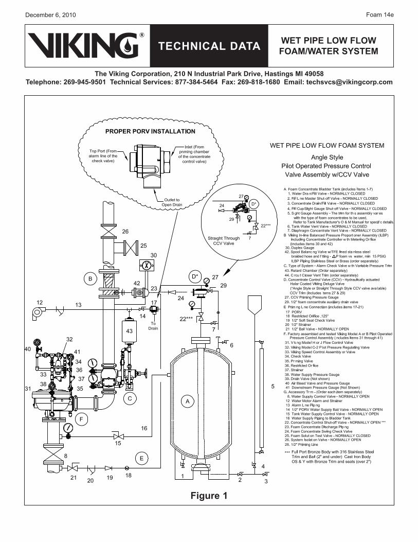
5. operatioNActuation of a sprinkler head allows system water to flow, causing the alarm check valve (C) clapper to open. The retard chamber (43) and alarm line (13) are pressurized, which causes the PORV (17) to operate. Pressure is relieved from priming chamber of Viking Halar® coated concentrate control deluge valve (D), allowing the valve to open. The bladder tank (A) is already pressurized by the water supply valve (15) and piping (16). System water pressure in the space between the flexible bladder and the inside surface of the tank causes the bladder to collapse, forcing foam concentrate out through the foam concentrate supply piping (23), Halar® coated concentrate control deluge valve (D), and to balancing valve (42) of ILBP assembly (B). The balancing valve (42) senses the inlet water pressure upstream of the concentrate controller (B) and adjusts the foam concentrate pressure to the same water pressure as the inlet to metering orifice of concentrate controller (B).
6. iNspeCtioN & maiNteNaNCeRefer to Wet Pipe Foam/Water System data page 10a-i, Section 6, for inspection and maintenance instructions for the wet pipedata page 10a-i, Section 6, for inspection and maintenance instructions for the wet pipeSection 6, for inspection and maintenance instructions for the wet pipe foam/water system. Refer to data page 534a-f in thepage 534a-f in thethe Viking Engineering and Design Data book for inspection and maintenance of the Viking pilot operated pressure control valve.

Wet pipe loW floW foam/Water systemteCHNiCal Data
December 6, 2010Foam 14d
the Viking Corporation, 210 N industrial park Drive, Hastings mi 49058telephone: 269-945-9501 technical services: 877-384-5464 fax: 269-818-1680 email: [email protected]
7. aVailaBilityThe Wet Pipe Low Flow Foam/Water System is available through a network of domestic and international distributors. See the Viking Corporation web site for closest distributor or contact The Viking Corporation.
8. GuaraNteeFor details of warranty, refer to Viking’s current list price schedule or contact Viking directly.
speCial NotesProvide a minimum of 5 pipe diameters of straight pipe on the inlet and outlet of the concentrate controller (B) to minimize turbu-lence inside the concentrate controller. Exception: The outlet for the tank water supply control valve (15) may be connected nearer to the inlet of the concentrate controller and should not cause excessive turbulence. However, if the outlet to the foam solution test valve (25) is located closer than 5 pipe diameters, there may be turbulence at high flow rates.
The combined total equivalent length of pipe (pipe length, plus equivalent lengths for fittings and valves) including both the water supply inlet piping (16) and the foam concentrate discharge piping (23), should not exceed 50 equivalent feet (15.2 meters). This will allow both pipes to be the same size as the foam liquid inlet to the concentrate controller. If the total equivalent length must exceed 50 feet (15.2 meters), then refer to the “Proportioning Equipment” section of this data book for the method of calculating these pipe sizes.
The CCV (D) and swing check valve (24) must be connected adjacent to the concentrate controller using pipe nipples as short as possible.
The alarm check valve must be installed using the variable pressure trim and retard chamber (30) to minimize false operation of the CCV (D). The releasing PORV (17) for the CCV (D) is activated by the operation of the alarm valve.
The ball valve (14) must be left in the open position, except when conducting alarm or flow test. Failure to close ball valve (14) before running an alarm or flow test will result in the unwanted discharge of foam concentrate. Once the test is completed, the ball valve (14) must be returned to the open position, or the foam CCV (D) will not operate, and the foam concentrate will not flow to the concentrate controller. WARNING: Turning off the alarm test shut-off valve during a fire may cause the concentrate control valve to close, stopping the flow of foam concentrate. The installing contractor should post a sign stating the same at alarm shut-off valve and/or install a monitor switch on the alarm shut-off valve.
The suggested location for a water flow switch, should one be required, is between the outlet of the alarm check valve (C) and the inlet to the concentrate controller.
Figures 1-3 are general schematics of the required piping arrangement. Refer to the appropriate technical data page for specific information regarding the valve, tank, and related trim and devices.
The technical information, statements, and recommendations contained in this manual are based on information and tests which, to the best of our knowledge, we believe to be dependable. It represents general guidelines only, and the accuracy or complete-ness thereof, are not guaranteed since conditions of handling and usage are outside our control. The purchaser should determine the suitability of the product for its intended use and assumes all risks and liability whatsoever in connection therewith.
A strainer is not required in the foam concentrate discharge piping (23) of bladder tank systems per NFPA Standards.
The foam deluge CCV (D) does not require any trim except for a 1/2” priming line (28), 1/2” auxiliary drain valve (29), and gauge with 3-way valve (27). Plug all remaining valve trim outlets. Refer to the “Valves” section of this data book to find the correct trim kit part number for the corresponding size of foam concentrate control Halar® coated deluge valve (D) required.
A.
B.
C.
D.
E.
F.
G.
H.
I.
J.
Wet pipe loW floW foam/Water systemteCHNiCal Data
December 6, 2010 Foam 14e
the Viking Corporation, 210 N industrial park Drive, Hastings mi 49058telephone: 269-945-9501 technical services: 877-384-5464 fax: 269-818-1680 email: [email protected]
figure 1

Wet pipe loW floW foam/Water systemteCHNiCal Data
December 6, 2010Foam 14f
the Viking Corporation, 210 N industrial park Drive, Hastings mi 49058telephone: 269-945-9501 technical services: 877-384-5464 fax: 269-818-1680 email: [email protected]
figure 2

Wet pipe loW floW foam/Water systemteCHNiCal Data
December 6, 2010 Foam 14g
the Viking Corporation, 210 N industrial park Drive, Hastings mi 49058telephone: 269-945-9501 technical services: 877-384-5464 fax: 269-818-1680 email: [email protected]
figure 3

Wet pipe loW floW foam/Water systemteCHNiCal Data
December 6, 2010Foam 14h
the Viking Corporation, 210 N industrial park Drive, Hastings mi 49058telephone: 269-945-9501 technical services: 877-384-5464 fax: 269-818-1680 email: [email protected]
For complete Wet Pipe Low Flow Foam/Water System, select Alarm Valve and Trim, Retard Chamber and Circuit Closer Vent Trim, Pilot Operated Pressure Control Valve, Foam Concentrate Control Valve and Trim, Foam Concentrate and ILBP, Bladder Tank and Accessories.
table 1
DesCriptioN NomiNalsiZe
partNumBer
Data paGe
alarm CHeCK ValVe
flange/flange
Flange Drilling Model J-1ANSI 3” 08235
26 a-g
ANSI 4” 08238ANSI 6” 08241ANSI 8” 08244
PN10/16 DN80 09108PN10/16 DN100 09109PN10/16 DN150 09110
PN10 DN200 09111PN16 DN200 12388
flange/Groove
Flange Drilling / Pipe O.D. Model J-1
ANSI / 89 mm 3” 08236
26 a-g
ANSI / 114 mm 4” 08239ANSI / 168 mm 6” 08242ANSI / 219 mm 8” 08245
PN10/16 / 89 mm DN80 09535PN10/16 / 114 mm DN100 09536PN10/16 / 168 mm DN150 09874
PN10 / 219 mm DN200 09877PN16 / 219 mm DN200 12389
Groove/Groove
Pipe O.D. Model J-189 mm 3” / DN80 08237
26 a-g114 mm 4” / DN100 08240165 mm DN150 09405168 mm 6” / DN150 08243219 mm 8” / DN200 08246
moDel J-1 alarm ValVe trim Brass
Vertical
3” / DN80 11428
27 a-c4” / DN100 114296” / DN150 114308” / DN200 11431
Horizontal
3” / DN80 11432
28 a-c4” / DN100 114336” / DN150 114348” / DN200 11435
DesCriptioN NomiNalsiZe
partNumBer Data paGe
CirCuit Closer VeNt Brass trim 08220
38 a-bmoDel C-1 retarDiNG CHamBer 05904B
(not included in the trim)
foam CoNCeNtrate CoNtrol ValVe Halar® CoateDangle style
61a-f
threaded Npt
Model & Pipe O.D.Model E-4 48 mm 1½” / DN40 09890Q/BModel E-2 60 mm 2” / DN50 08361Q/B
straight throughthreaded
NptPipe O.D. Model F-2
NPT 65 mm 2½” 12402Q/B
Groove/Groove
Pipe O.D. Model F-248 mm 1½” / DN40 12127Q/B60 mm 2” / DN50 12058Q/B73 mm 2½” / DN65 12404Q/B
foam CoNCeNtrate CoNtrol ValVe trim
use with angle style Valve
Galvanized
61 a-f
1½” / DN40 080982” / DN50 08099
Brass1½” / DN40 096942” / DN50 09695
use with straight through Valves
Galvanized1½” / DN40 12848-12” / DN50 12848-1
2½” / DN65 12929-1Brass
1½” / DN40 12848-22” / DN50 12848-2
2½” / DN65 12929-2
DesCriptioN taNKsiZe
partNumBer Data paGe
HoriZoNtal BlaDDer taNK 50 - 4500 Gallon CHBT2-xxxx *240 a-h
VertiCal BlaDDer taNK 25 - 4500 Gallon CVBT2-xxxx ** Where xxxx is the tank size

Wet pipe loW floW foam/Water systemteCHNiCal Data
December 6, 2010 Foam 14i
the Viking Corporation, 210 N industrial park Drive, Hastings mi 49058telephone: 269-945-9501 technical services: 877-384-5464 fax: 269-818-1680 email: [email protected]
table 2
DesCriptioN NomiNalsiZe
partNumBer
Data paGe
foam CoNCeNtrate sWiNG CHeCK ValVe
1½” / DN40 99S-0150 -
2” / DN50 99S-0200 -
2½” / DN65 05497C 803 a-d
foam solutioN test ValVe
Grooved Butterfly Valve
2½” / DN65 01G-0250
-
3” / DN80 01G-0300
4” / DN100 01G-0400
6” / DN150 01G-0600
8” / DN200 01G-0800
system isolatioN ValVe
Grooved Butterfly Valve
2½” / DN65 01G-0250
-
3” / DN80 01G-0300
4” / DN100 01G-0400
6” / DN150 01G-0600
8” / DN200 01G-0800
Water supply CoNtrol ValVe
os & y
2½” / DN65 8068A-0250
-
3” / DN80 8068A-0300
4” / DN100 8068A-0400
6” / DN150 8068A-0600
8” / DN200 8068A-0800
foam CoNCeNtrate sHut-off ValVe
Ball Valve1½” / DN40 T595Y66-0150
-2” / DN50 T595Y66-0200
aCCessories for foam/Water spriNKler systems
moDel D-1 porV ½” / DN15 13598 287 a-b
1/8” / 3 mm restriCteD orifiCe ½” / DN15 06555A -
soft seat CHeCK ValVe ½” / DN15 03945A -
y straiNer ½” / DN15 01054A -
Ball ValVe ½” / DN15 10355 -
CoNCeNtrate CoNtrol ValVe primiNG CoNNeCtioN pKG.
Required to connect priming chamber 10985 -BlaDDer taNK Water supply CoNtrol ValVe
Ball Valve 1½” / DN40 WBV-0150
-Ball Valve 2” / DN50 WBV-0200
OS & Y 2½” / DN65 8068A-0250OS & Y 3” / DN80 8068A-0300
foam CoNCeNtrates aND ilBp assemBliesfoam CoNCeNtrate ilBp assemBly
DesCriptioN Base part NumBer
foam CoNCeNtrate
Data paGe
NomiNal siZe
ViKiNG partNumBer
ilBp Data paGe
1% AFFFC103 F14969 100 a-b
2½” F15006/A
171 a-d
3” F15012/A4” F15018/A6” F15025/A8” F15032/A
3% AFFFC303 F14970 101 a-b
2½” F15006/B3” F15012/B4” F15018/B6” F15025/B8” F15032/B
3% AFFF MSC301 MS F14971 102 a-b
2½” F15006/C3” F15012/C4” F15018/C6” F15025/C8” F15032/C
3% - 6% AFFF@ 3% C363 F14973 103 a-b
2½” F15006/D3” F15012/D4” F15018/D6” F15025/D8” F15032/D
3% - 6% AFFF @ 3% C363 F14973 103 a-b
2½” F15006/E3” F15012/E4” F15018/E6” F15025/E8” F15032/E
3% AR-AFFFCUG F14972 104 a-b
2½” F15006/J3” F15012/J4” F15018/J6” F15025/J8” F15032/J
2% Hi ExC2 F14974 105 a-b
2½” F15006/H3” F15012/H4” F15018/H6” F15025/H8” F15032/H

Wet pipe loW floW foam/Water systemteCHNiCal Data
December 6, 2010Foam 14j
the Viking Corporation, 210 N industrial park Drive, Hastings mi 49058telephone: 269-945-9501 technical services: 877-384-5464 fax: 269-818-1680 email: [email protected]
DesCriptioN NomiNalsiZe
partNumBer
Data paGe
pilot operateD pressure CoNtrol ValVesstraiGHt tHrouGH ValVes
(iNCluDes moDel B-1 GalVaNiZeD trim. Brass or staiNless steel also aVailaBle)
Horizontal arrangement
threaded
Pipe O.D.
536 a-i
48 mm 1½” / DN40 1277460 mm 2” / DN50 1277665 mm 2½” / DN65 12778
flange/flange
Flange DrillingANSI 3” / DN80 12782ANSI 4” / DN100 12785ANSI 6” / DN150 12788ANSI 8” / DN200 12790
flange/Groove
Flange Drilling / Pipe O.D.ANSI / 89 mm 3” / DN80 12781
ANSI / 114 mm 4” / DN100 12784ANSI / 168 mm 6” / DN150 12787
Groove/Groove
Pipe O.D.48 mm 1½” / DN40 1277560 mm 2 ” / DN50 1277773 mm 2½” / DN65 1277989 mm 3” / DN80 12780
114 mm 4” / DN100 12783168 mm 6” / DN150 12786219 mm 8” / DN200 12789
Vertical arrangement
threaded
Pipe O.D.
536 a-i
48 mm 1½” / DN40 1279160 mm 2” / DN50 1279365 mm 2½” / DN65 12795
flange/flange
Flange DrillingANSI 3” / DN80 12799ANSI 4” / DN100 12802ANSI 6” / DN150 12805ANSI 8” / DN200 12807
flange/Groove
Flange Drilling / Pipe O.D.ANSI / 89 mm 3” / DN80 12798
ANSI / 114 mm 4” / DN100 12801ANSI / 168 mm 6” / DN150 12804
Groove/Groove
Pipe O.D.48 mm 1½” / DN40 1279260 mm 2” / DN50 1279473 mm 2½” / DN65 1279689 mm 3” / DN80 12797
114 mm 4” / DN100 12800168 mm 6” / DN150 12803219 mm 8” / DN200 12806
DesCriptioN NomiNalsiZe
partNumBer
Data paGe
pilot operateD pressure CoNtrol ValVesaNGle style ValVes
(iNCluDes moDel a-2 GalVaNiZeD trim. Brass or staiNless steel also aVailaBle)
threadedPipe O.D.
534 a-f
60 mm 2” / DN50 10793
flange/flange
Flange DrillingANSI 3” / DN80 10801ANSI 4” / DN100 10795ANSI 6” / DN150 10807
PN10/16 DN80 10801FFPN1016PN10/16 DN100 10795FFPN1016PN10/16 DN150 10807FFPN1016
flange/Groove
Flange Drilling / Pipe O.D.ANSI / 89 mm 3” / DN80 10800
ANSI / 114 mm 4” / DN100 10794ANSI / 168 mm 6” / DN150 10806
table 3
Form No. F_012696 Revised page replaces page Foam 14a-j, dated June 1, 2008.(Added Special Notes section on page 14d and updated Table 3.)