technical data sheet - producetech - insulate… · technical data sheet ... for vertical or...
TRANSCRIPT
Technical Data SheetARCHITECTURAL PAnEL wITH ExPAndEd PoLysTyREnE CoRE
1.1 InTRodUCTIon
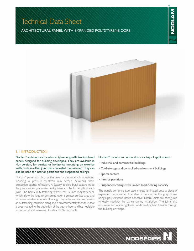
norlam® architectural panels are high-energy-efficient insulated panels designed for building envelopes. They are available in « L » version, for vertical or horizontal mounting on exterior walls, with an offset joint that concealed the fastener. They can also be used for interior partitions and suspended ceilings.
Norlam® panels stand out as the result of a number of innovations, including a pressure-equalized rain screen delivering triple protection against infiltration. A factory applied butyl sealant inside the joint cavities guarantees air-tightness on the full length of each joint. The heavy-duty fastening system has 12-inch-long fasteners, which allow the load to be spread over a greater surface area and increases resistance to wind loading. The polystyrene core delivers an outstanding insulation rating and is environmentally friendly in that it does not add to the depletion of the ozone layer and has negligible impact on global warming. It is also 100% recyclable.
norlam® panels can be found in a variety of applications :
• Industrial and commercial buildings
• Cold-storage and controlled-environment buildings
• sports centers
• Interior partitions
• suspended ceilings with limited load-bearing capacity
The panels comprise two steel sheets laminated onto a piece of expanded polystyrene. The steel is bonded to the polystyrene using a polyurethane-based adhesive. Lateral joints are configured to easily interlock the panels during installation. The joints also ensure air and water tightness, while limiting heat transfer through the building envelope.
1.2 | General presentation
1.2 InTEgRATEd PREssURE-EqUALIzEd RAInsCREEn
Water infiltration can cause major problems to wall systems and shorten building life. The rainscreen concept is largely used with curtain-wall systems to control potential water infiltration. Quite some time ago, Norbec Architectural adapted this concept to Norlam®panels and, more recently, to Norex® and Noroc® panels.
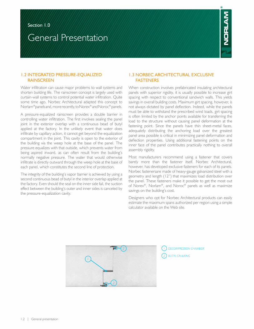
A pressure-equalized rainscreen provides a double barrier in controlling water infiltration. The first involves sealing the panel joint in the exterior overlap with a continuous bead of butyl applied at the factory. In the unlikely event that water does infiltrate by capillary action, it cannot get beyond the equalization compartment in the joint. This cavity is open to the exterior of the building via the weep hole at the base of the panel. The pressure equalizes with that outside, which prevents water from being aspired inward, as can often result from the building’s normally negative pressure. The water that would otherwise infiltrate is directly outward through the weep hole at the base of each panel, which constitutes the second line of protection.
The integrity of the building’s vapor barrier is achieved by using a second continuous bead of butyl in the interior overlap applied at the factory. Even should the seal on the inner side fail, the suction effect between the building’s outer and inner sides is canceled by the pressure-equalization cavity.
1.3 noRbEC ARCHITECTURAL ExCLUsIvE FAsTEnERs
When construction involves prefabricated insulating architectural panels with superior rigidity, it is usually possible to increase girt spacing with respect to conventional sandwich walls. This yields savings in overall building costs. Maximum girt spacing, however, is not always dictated by panel deflection. Indeed, while the panels must be able to withstand the prescribed wind loads, girt spacing is often limited by the anchor points available for transferring the load to the structure without causing panel deformation at the fastening point. Since the panels have thin sheet-metal faces, adequately distributing the anchoring load over the greatest panel area possible is critical in minimizing panel deformation and deflection properties. Using additional fastening points on the inner face of the panel contributes practically nothing to overall assembly rigidity.
Most manufacturers recommend using a fastener that covers barely more than the fastener itself. Norbec Architectural, however, has developed exclusive fasteners for each of its panels. Norbec fastenersare made of heavy-gauge galvanized steel with a geometry and length (12’’) that maximizes load distribution over the panel. These fasteners make it possible to get the most out of Norex®, Norlam®, and Noroc® panels as well as maximize savings on the building’s cost.
Designers who opt for Norbec Architectural products can easily estimate the maximum spans authorized per region using a simple calculator available on the Web site.
decompression chamber1
bUTYL caULking21
2
2
section 1.0
General Presentation

1.4 MAIn AdvAnTAgEs
Excellent thermal performance
• Guaranteed thermal performance and air tightness throughout its life cycle.
• No cavities, moisture penetration, thermal bridges, risk of interstitial condensation, or lack of insulation.
• Pressure-equalized rain screen ensures that the building envelope is well sealed.
• Factory-applied butyl joint sealer ensures maximum seal.
Installation
• Simple construction.• Yields savings because installation time can be
accurately estimated, even if weather conditions are poor.
• Reduces installation time by 50% over multiple assembly systems.
• Exclusive and superior fastening system.• Wider girt spacing reduces costs.• Can be used as a roof parapet.
Environment• The materials are environmentally friendly and
nontoxic.
• Polystyrene has an ozone depletion potential (odP) of zero and a negligible global warming potential (gwP).
• Life expectancy of up to 40 years.
• The materials contain no CFCs or HCFCs.
• Polystyrene and steel are 100% reusable.
• Helps reduce carbon dioxide (CO2) emissions by providing better energy efficiency and being part of a sustainable-development policy.
• Can contribute to obtaining LEEd certification for a project.
Appearance
• Lends itself to more creative concepts, while ensuring high construction quality.
• A variety of visual proportions are possible through the use of horizontal or vertical geometry.
• Choice of profiles, colours, and textures.
• Can be harmonized with other types of panels (norex® and noroc®).
• Exclusive reverse fastening system for anchoring noble materials, decorative facings and architectural elements.
Exclusive structural anchoring system
Listing
Compliance with several construction standards such as ULC, AsTM, and AAMA. Products are subjected to laboratory testing according to recognized methods to meet the strictest standards of mechanical performance and fire resistance.
1.3 | Norlam® Architectural Panel
section 1.0
General Presentation

1.5 PAnEL CoMPonEnT MATERIALs
1.5.1 Insulation
Standard panels are built using type-1 expanded polystyrene, available in several thicknesses depending on requirements. Type-II polystyrene is available as an option.
1.5.2 steel
The steel is high-quality, hot-dipped galvanized steel that meets AsTM A653/A653M quality requirements. It is available in a range of colours and textures.
1.5.3 Finish
Each of the paint systems available, including the Perspectra SeriesTM, features outstanding fade resistance. We can guide you in selecting the best paint system for you, depending on the environment and conditions to which the surface will be exposed.
we offer the following standard colours for the panel's external faces:
• White white (QC 18317) • Bone white (QC 18273)• Stone grey (QC 18305) • Charcoal (QC 18306)• Tan (QC 18315) • Heron blue (QC 18330)• Bright white (QC 18783) • Interior white (QC 7973)
A broader range of colours is available upon request.
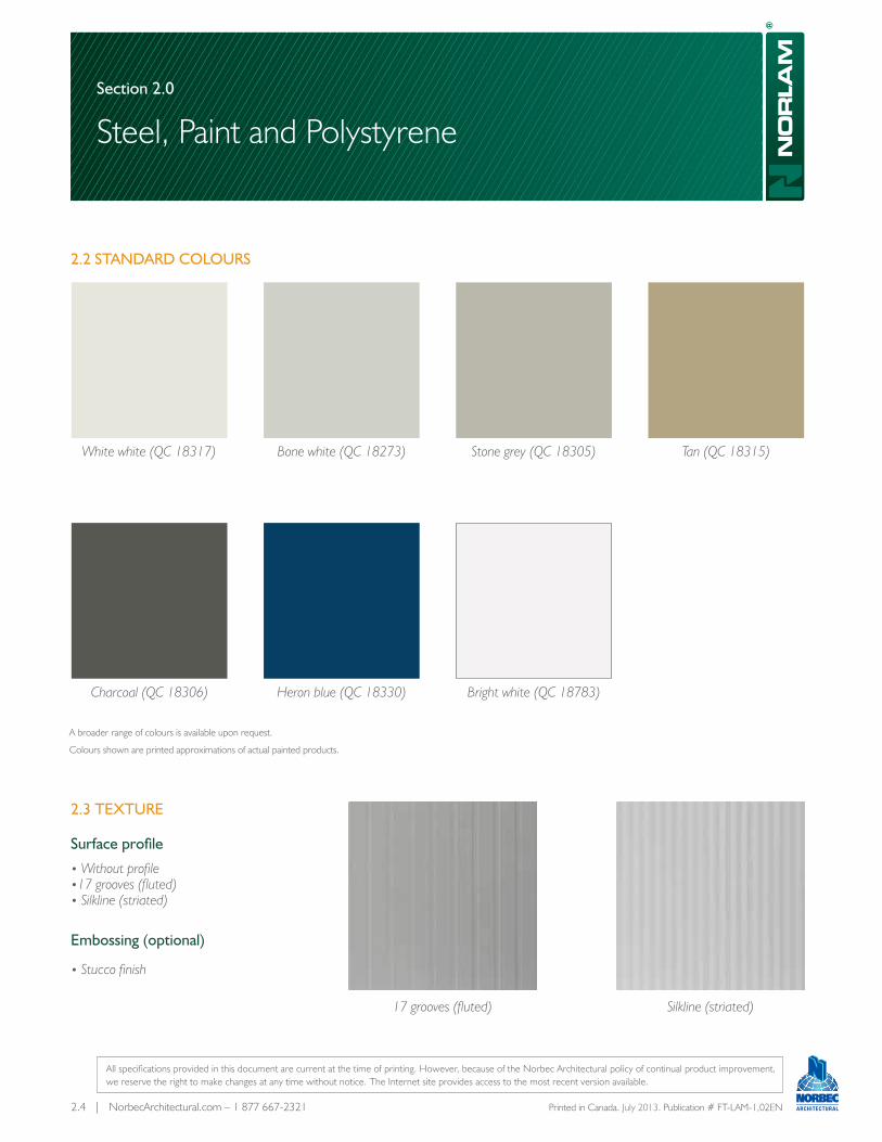
1.5.4 Texture
1.5.4.1 surface profile: • Without profile • 17 grooves (fluted) • Silkline (striated)
1.5.4.2 Embossing (optional): • Stucco finish
1.6 PAnEL dEsIgn
1.6.1 Physical Properties
nominal width: 45 ½” *
Length: 6’ to 49’
Thickness: 3”, 4”, 5”, 6”, 7½” and 10”
Insulation rating: • With type I polystyrene, R11,85 to R39,50 • With type II polystyrene, R12,60 to R42,00
steel, inner face: 0,019” (0,483 mm) standard thickness 0,027” (0,686 mm) optional thickness
steel, outer face: 0,019” (0,483 mm) standard thickness 0,027” (0,686 mm) optional thickness
* The final module width may change due to variations in fabrication and installation. We do not recommend designing a panel arrangement in which the module width plays a critical role.
1.6.2 Listing
The laboratory tests are carried out by recognized firms and in accordance with specific standards. Section 3.0 of this data sheet describes each test and the results obtained as part of our research and development program.
1.6.3 Joints
1.4 | NorbecArchitectural.com – 1 877 667-2321 Printed in Canada. July 2013 Publication # FT-LAM-1,01EN
section 1.0
General Presentation
Norlam® – L: v
• Offset joint with concealed fasteners• Vertical or horizontal mounting
All specifications provided in this document are current at the time of printing. However, because of the Norbec Architectural policy of continual product improvement, we reserve the right to make changes at any time without notice. The Internet site provides access to the most recent version available.

section 2.0
Steel, Paint and Polystyrene
2.1 | Norlam® Architectural Panels
2.1 InTRodUCTIon
Norlam® architectural panels are made of superior-quality, hot-galvanized steel.Colour is provided by the Perspectra SeriesTM paint system that uses cutting-edge technology for the pre-treatment, undercoat and topcoat with silicone-modified polyester. This system provides 40-years film integrity for most colours. Chalk resistance and colour retention are 30 years. These features apply everywhere in Canada and the continental United States. Moreover, inorganic pigments yield improved colour retention and resistance to fading as a result of UV exposure.
The process begins with chemical pre-treatment of the sheet steel, which enhances the bonding of the primer to the metal surface. The flexible high-adherence primer is then applied to the pre-treated surface in order to yield greater corrosion resistance, especially along edge, surface grooves and bends. The topcoat is a silicon-modified polyester paint in a colour chosen specifically for the application. The concealed face of the steel is pre-treated for optimal adhesion of the insulation.
The standard colours in the Perspectra SeriesTM were developed to provide a total solar reflection (TSR) of at least 25%. Furthermore, whites that reflects sunlight yield TSR values of 0.65 to 0.70, which helps keep the building cooler.
Paint systems other than the Perspectra SeriesTM are available, such as polyu-rethane, fluoropolymer base on PVDF resin or polyvinyl chloride (PVC). Before choosing a paint system, the designer must take into account the type of environment and exposure conditions of the wall covering. This is important because a system's performance generally depends on the length of exposure to moisture, UV radiation, salt air and chemicals. Furthermore, scratch and abrasion resistance might also be a concern according to the type of traffic near the covering.
The colours shown in table 2.2 are standard for 26-gauge steel. Ask about the availability and the additional costs for your choice of colours and steel gauges. Contact our sales department for details about steel protection systems for your applications.
2.2 | Steel, Paint and Polystyrene
Covering Approved by the Canadian Food Inspection Agency and the United states department of Agriculture
System Colour Code Colour CFIA USDA
Silicone-modified polyester QC 18317 White white Yes Yes
Silicone-modified polyester QC 18273 Bone white Yes Yes
Silicone-modified polyester QC 18305 Stone grey No No
Silicone-modified polyester QC 18306 Charcoal No No
Silicone-modified polyester QC 18315 Tan Yes Yes
Silicone-modified polyester QC 18330 Heron blue No No
Silicone-modified polyester QC 18783 Bright white Yes Yes
Polyester QC 7973 * White Yes Yes
* For interior use only
Covering Approved by the Canadian Food Inspection Agency and the United states department of Agriculture
Types Benefits Limitations Uses
Polyester (For indoor use only)
• Cost• Scratch resistance• CFIA & USDA approvals
• Poor gloss retention• Colour change• UV exposure
• Controlled Environment• Indoor applications
Silicone-modified polyester (Perspectra Series)
• Scratch resistance• Film integrity: 40 years• Chalk resistance: 30 years
• Corrosion resistance• Gloss retention
• Outdoor wall covering, including light industrial or commercial use
Polyurethane• Weathering• Superior corrosion resistance• Formability
• Scratch resistance• Outdoor wall covering,
including moderate industrial or commercial use
Fluoropolymer PVDF Resin (Series 10 000)
• Weathering• Colour stability under extreme exposure to UV• Formability
• High cost• Scratch resistance • High exposure to UV comparable to
southern US states
Polyvinyl Chloride, PVC Plastisol(Barrier)
• Resistance to chemical products• Corrosion resistance• Scratch resistance
• Chalking• Gloss retention • Covering in a corrosive environment
/
section 2.0
Steel, Paint and Polystyrene

2.3 | Norlam® Architectural Panels
Main Physical Properties of Polystyrene*
Property Method Type I Type II
R Value (ft2 ºF h / Btu) ASTM C518 3,75 4,00
Density (lb / ft3) – 1,00 1,25
Compression resistance (psi) ASTM D1621 8,00 16,00
Flex resistance (psi) ASTM C203 25,00 35,00
Water vapor permeability (perms / in) ASTM E96/E96M 5,25 3,50
Water absorption (max.) ASTM D2842 6,0 % 4,0 %
Dimensional stability (max.) ASTM D2126 1,5 % 1,5 %
Linear dilation coefficient (in / in / ºF) ASTM D696 3,5 x 10⁻⁵ 3,5 x 10⁻⁵
* Source BASF
Panel weight According to Thickness and Length (lb)**
Thickness (in) Panel Length (ft) Weight (lb. / pi2)
8 16 24 32 40 45 –
3 58 117 176 235 294 330 2,2
4 62 124 185 247 309 348 2,3
5 65 130 195 260 325 366 2,4
6 68 136 204 273 341 384 2,5
7 ½ 71 142 214 285 357 401 2,7
10 80 161 242 323 404 454 2,9
** Calculations based on 26-gauge steel and type-2 polystyrene (1.25 pcf)
section 2.0
Steel, Paint and Polystyrene
2.3 TExTURE
surface profile
• Without profile •17 grooves (fluted) • silkline (striated)
Embossing (optional)
• stucco finish
17 grooves (fluted) silkline (striated)
2.4 | NorbecArchitectural.com – 1 877 667-2321 Printed in Canada. July 2013. Publication # FT-LAM-1,02EN
A broader range of colours is available upon request.
Colours shown are printed approximations of actual painted products.
2.2 sTAndARd CoLoURs
White white (Qc 18317) bone white (Qc 18273) stone grey (Qc 18305) Tan (Qc 18315)
charcoal (Qc 18306) heron blue (Qc 18330) bright white (Qc 18783)
section 2.0
Steel, Paint and Polystyrene
All specifications provided in this document are current at the time of printing. However, because of the Norbec Architectural policy of continual product improvement, we reserve the right to make changes at any time without notice. The Internet site provides access to the most recent version available.

3.1 | Norlam® Architectural Panels
section 3.0
Listing for Architectural Panels
3.1 gEnERAL dEsCRIPTIon
The panels are designed to support dead loads, live loads and wind loads. The load limits applied to the panels vary proportionally based on thickness as well as fastener load capacity. Panel behavior is similar to that of an I-beam, where the steel surface acts like the beam's flanges and the insulation like its web. When the panel is loaded, the compressive and flexural forces absorbed by the steel and stabilized by the polystyrene so as to resist buckling.
The following subsections briefly describe the laboratory tests that were per-formed as part of research and development. For further information on the tests, please contact our sales department.
3.2 | Certification of the Architectural Panels
3.2 PRoPERTIEs And PERFoRMAnCE TEsTs
Laboratory tests determine the performance and usage limitations of Norlam® panels in accordance with Canadian (ULC) and American (ASTM, and AAMA) standards. The National Building Code NBC-2005, section B, part 3, sentences 3.1.5.12 (6) and (7) define the standards concerning the use of panels with combustible insulation.
3.3 AsTM E72
standard test method of conducting strength tests of panels for building construction
Deflection testing is carried out in accordance with the provisions of the depressurization-chamber method in ASTM E72. This method consists in submitting panel samples to a series of uniformly distributed static loads and measuring the resultant deflection.
The loads are gradually increased until panel failure. The results make it possible to determine the maximum loads for simple and multiple spans, and for deflection limits of L/180 (wall), L/240 (roof), and L/360 (brick veneer).
The results obtained show the maximum loads based on free span and panel thickness. The load calculations in psf were carried out according to three distinct limitation criteria. The first criterion is maximum panel deflection based on its free span; the second is total maximum load without permanent deformation; and the third maximum load is over supports. Based on the rupture mode, the loads recorded were limited to the ultimate load divided by 1.5 (safety factor).
The results demonstrate that the bending stiffness (EI) varies proportionally to the square of panel thickness. This demonstrates that, for the loads considered, the assembly behaves like a partially solid assembly comprised of rigid composites and that it benefits fully from the separation of the steel sheets from the neutral axis.
3.4 AsTM E283
standard test method for determining the rate of air leakage through the exterior windows, curtain walls and doors under specified pressure differences across the specimen
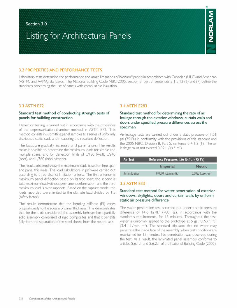
Air-leakage tests are carried out under a static pressure of 1.56 psi (75 Pa) in conformity with the provisions of this standard and the 2005 NBC, Division B, Part 5, sentence 5.4.1.2 (1). The air leakage must not exceed 0.02 L / (s * m2).
Air Test Reference Pressure: 1.56 lb./ft.2 (75 Pa)
Imperial Metric
Air infiltration 0.0010 ft.3/min.-ft.2 0.0053 L./sec.-m2
3.5 AsTM E331
standard test method for water penetration of exterior windows, skylights, doors and curtain walls by uniform static air pressure difference
The water penetration test is carried out under a static pressure difference of 14.6 lbs / ft.2 (700 Pa.), in accordance with the standard’s requirements, for 15 minutes. Throughout the test, water is uniformly applied to the prototype at 5 gal. U.S./ h. ft.2 (3.41 L / min.-m2). The standard stipulates that no water may penetrate the inside face of the assembly when test conditions are maintained for 15 minutes. No penetration was observed during the test. As a result, the laminated panel assembly conforms to articles 5.6.1.1 and 5.6.2.1 of the National Building Code (2005).
section 3.0
Listing for Architectural Panels

3.3 | Norlam® Architectural Panels
3.6 AAMA 501.1
standard test method for exterior windows, curtain walls and doors for water penetration using dynamic pressure
The water penetration test was performed using a dynamic pres-sure difference of 14.6 lb. / ft.2 (700 Pa) in accordance with the standard’s requirements. Throughout the duration of the test, wa-ter is uniformly applied to the prototype at 5 gal. U.S. / h. ft.2 (3.41 L / min.-m.2). The pressure difference is produced by an aircraft engine with a propeller measuring 13.5 ft. (4.11m.) in diameter.
The standard stipulates that no water may penetrate the inside face of the assembly when test conditions are maintained for 15 minutes. No penetration was observed during the test. As a re-sult, the laminated panel assembly conforms to articles 5.6.1.1 and 5.6.2.1 of the National Building Code (2005).
3.7 AsTM E330
standard test method for structural performance of exterior windows, doors, skylights and curtain walls by uniform static air pressure difference
The structural-performance test is carried out using positive and negative loads equal to the design pressure, that is 30 psf (1.45 kPa), in accordance with the test requirements. The standard allows a maximum panel deflection that is the smaller of L /180 or ¾".
3.8 AAMA 501.5
Test method for thermal cycling of exterior wall
The thermal-cycling test involves a total of seven cycles during which the exterior temperature ranges from -22 ºF (-30 ºC) to 180 ºF (82 ºC) over a period of 8 hours. The standard allows no damage or permanent deformation that could affect the wall’s appearance or performance. Following the cycles, no damage, breakage or permanent distortion was observed.
3.9 AsTM C236 – 89 (1993) E1
standard test method for steady-state thermal performance of building assemblies by means of a guarded hot box
The thermal test was performed in accordance with the standard’s requirements, i.e., in a guarded hot box under controlled temperature and humidity. It determines the overall U value of panel assemblies and condensation resistance.
Maximum relative humidity for an internal Temperature of 68 °F
External temperature in °F 32 23 14 5 -4 -13 -22
Wall surface* 88 % 87 % 85 % 81 % 79 % 77 % 75 %
* The maximum relative humidity levels may vary according to inside temperature.
3.10 qUALITATIvE FIRE-REsIsTAnCE TEsTs FoR ARCHITECTURAL PAnELs
The tests performed by the ULC (Underwriters’ Laboratories of Canada) do not establish overall fire resistance of the panel for a specific application. They evaluate the behaviour of the materials or assemblies when exposed to fire in laboratory conditions.
section 3.0
Listing for Architectural Panels

3.4 | NorbecArchitectural.com – 1 877 667-2321 Printed in Canada. July 2013. Publication # FT-LAM-1,03EN
section 3.0
Listing for Architectural Panels
3.11 CAn/ULC s102, M88,
standard test method for surface burning characteristics of building materials and assemblies
The test method, which establishes the combustion characteristics of construction materials, applies to all construction materials that, either as a result of their structural qualities or the way in which they are applied, can remain in position on their own or a sample of a thickness comparable to that recommended for use can be supported in the furnace.
The main purpose of this test is to determine the combustion characteristics of various materials or assemblies by evaluating the flame-spread rating of a surface exposed to an experimental flame. This makes it possible to establish a baseline for comparing surface combustion characteristics of various materials in the assemblies without taking into account all of the end-use parameters that might affect surface-combustion characteristics. Sentences 3.1.5.12. (6) and (7) of the 2005 NBC require an index less than 500.
Although the smoke-producing power and flame-spread rating are recorded during this test, there is not necessarily a relationship between these data.
This test method makes it possible to observe how the material performs during the exposure time; it cannot be used as a basis for deciding if they should be used after test exposure.
This method does not establish the performance levels for specific uses. It provides the means for evaluating the behaviour of materials, products, and assemblies when exposed to a specific flame under controlled laboratory conditions.
3.12 CAn / ULC – s138
standard test method for fire growth of insulated building panel in a full-scale room configuration (oRd C376-1995)
This test method is used to determine the contribution to fire growth provided by a non-loadbearing insulated building panel installed in a sprinkled room configuration. Clause 3.1.5.12. (7) (e) of the NBC (2005) requires that the panel meet this standard.
The insulated building panels investigated by this test method are of the factory-assembled type and intended for use as exterior or interior walls, ceilings, or roofs. This standard presumes that these panels are not backed by other materials or constructions in typical installation practice. If the panels are designed for installation with backing, the test specimen shall be installed and assessed consistently with its intended use.
This test method measures the time to flashover under specified test conditions. Provisions are made to measure ignitability, smoke obscuration, rate of fire growth, and rate of heat release of the test panels.
This method was not designed to determine fire resistance of insulated building panels. Furthermore, this test method does not investigate the toxic hazard posed by the products of combustion.
These exposure tests were not designed to represent all fire conditions. It is probable that the conditions will vary according to changes in the scope, nature, and distribution of the fire load, ventilation, size, and configuration of the installed assembly. These requirements offer a relative measure of how comparable assemblies behave when exposed to specific fire conditions.
This standard must be used to measure and describe the behaviour of materials, products, and assemblies to the heat and flame of controlled conditions.
Test Results: CAn / ULC – s138
• The heat measured never exceeded 20 kW/m2 during a 15 min test with sprinklers.
• The temperature measured never exceeded 600 °C during a 15 min test with sprinklers.
• No flames appeared in the setup opening during a 15 min test with sprinklers.
Test Results: CAn/ULC s102, M88
Material Flame Smoke Spread Rating Density
Norlam®– L Panel 50 - 145 405 - 475
Polystyrene type II 290 over 670
All specifications provided in this document are current at the time of printing. However, because of the Norbec Architectural policy of continual product improvement, we reserve the right to make changes at any time without notice. The Internet site provides access to the most recent version available.

4.1 | Norlam® Architectural Panels
Section 4.0
Results of Deflection Tests according to ASTM E72
4.1 InTroducTIon
Deflection testing is carried out in accordance with the provisions of the depressurization-chamber method in ASTM E72. This method consists in submitting panel samples to a series of uniformly distributed static loads and measuring the resultant deflection.
The loads are gradually increased until panel failure. The results make it possible to determine the maximum loads for simple and multiple spans, and for deflection limits of L/180 (wall), L/240 (roof), and L/360 (brick veneer).
The results obtained show the maximum loads based on free span and panel thickness. The load calculations in psf were carried out according to three distinct limitation criteria. The first criterion is maximum panel deflection based on its free span; the second is total maximum load without permanent deformation; and the third is maximum load over supports. Based on the rupture mode, the loads recorded were limited to the ultimate load divided by 1.5 (safety factor).
The results demonstrate that the bending stiffness (EI) varies proportionally to the square of panel thickness. Therefore, for the loads considered, the assembly behaves like a partially solid assembly comprised of rigid composites and that it benefits fully from the separation of the steel sheets from the neutral axis.

4.2 | Results of deflexion tests according to ASTM E72
4.1 Load TabLe
Single Span, L/180 (psf)
Span (ft) Thickness (in)
3 4 5 6 7 1/2 10
6 52 52 56 62 62 66
7 44 44 48 53 53 57
8 39 39 42 46 47 50
9 34 35 37 41 41 44
10 27 31 34 37 37 40
11 21 28 31 34 34 36
12 16 26 28 31 31 33
13 12 24 26 29 29 31
14 10 22 24 26 27 28
15 8 21 22 25 25 26
16 7 19 21 23 23 25
17 6 16 20 22 22 23
18 5 14 19 21 21 22
19 – 12 17 19 20 21
20 – 10 15 16 19 20
21 – 9 13 14 17 19
22 – 8 11 12 15 18
23 – 7 10 11 13 17
24 – 6 8 9 11 15
25 – 5 8 8 10 13
26 – 5 7 7 9 12
27 – – 6 7 8 11
28 – – 5 6 7 9
29 – – 5 5 6 8
30 – – – 5 6 8
4.2 Load TabLe
Multiple Span, L/180 (psf)
Span (ft) Thickness (in)
3 4 5 6 7 1/2 10
6 52 52 56 62 62 66
7 44 44 48 53 53 57
8 39 39 42 46 47 50
9 34 35 37 41 41 44
10 31 31 34 37 37 40
11 28 28 31 34 34 36
12 26 26 28 31 31 33
13 24 24 26 29 29 31
14 22 22 24 26 27 28
15 20 21 22 25 25 26
16 16 19 21 23 23 25
17 13 18 20 22 22 23
18 11 17 19 21 21 22
19 10 16 18 20 20 21
20 8 16 17 19 19 20
21 7 15 16 18 18 19
22 6 14 15 17 17 18
23 5 14 15 16 16 17
24 5 13 14 15 16 17
25 – 12 13 15 15 16
26 – 11 13 14 14 15
27 – 10 12 14 14 15
28 – 9 12 13 13 14
29 – 8 12 13 13 14
30 – 7 10 12 12 13
Section 4.0
Results of Deflection Tests according to ASTM E72
NOTES:1) Above values were obtained using a 26 gauge steel and a Silkline profile on each faces.2) The tables are showing values limited by the flectional stress, the support points stress and the deflection of a panel. The most limiting criteria determines the design load shown.3) The tables do not consider connection loads and installation location. The calculation tool available on our web site allows you to obtain a girt spacing evaluation which
is considering all these factors.

4.3 | Norlam® Architectural Panels
4.3 Load TabLe
Single Span, L / 240 (psf)
Span (ft) Thickness (in)
3 4 5 6 7 1/2 10
6 52 52 56 62 62 66
7 44 44 48 53 53 57
8 39 39 42 46 47 50
9 28 35 37 41 41 44
10 21 31 34 37 37 40
11 15 28 31 34 34 36
12 12 26 28 31 31 33
13 9 24 26 29 29 31
14 7 22 24 26 27 28
15 6 18 22 25 25 26
16 5 15 21 23 23 25
17 – 12 18 20 22 23
18 – 10 15 17 20 22
19 – 9 13 14 17 21
20 – 8 11 12 15 19
21 – 7 10 10 13 17
22 – 6 8 9 11 15
23 – 5 7 8 10 13
24 – – 6 7 9 11
25 – – 6 6 8 10
26 – – 5 6 7 9
27 – – – 5 6 8
28 – – – – 5 7
29 – – – – 5 6
30 – – – – – 6
4.4 Load TabLe
Multiple Span, L / 240 (psf)
Span (ft) Thickness (in)
3 4 5 6 7 1/2 10
6 52 52 56 62 62 66
7 44 44 48 53 53 57
8 39 39 42 46 47 50
9 34 35 37 41 41 44
10 31 31 34 37 37 40
11 28 28 31 34 34 36
12 26 26 28 31 31 33
13 23 24 26 29 29 31
14 18 22 24 26 27 28
15 15 21 22 25 25 26
16 12 19 21 23 23 25
17 10 18 20 22 22 23
18 8 17 19 21 21 22
19 7 16 18 20 20 21
20 6 16 17 19 19 20
21 5 15 16 18 18 19
22 5 14 15 17 17 18
23 – 12 15 16 16 17
24 – 11 14 15 16 17
25 – 9 13 15 15 16
26 – 8 12 13 14 15
27 – 7 11 12 14 15
28 – 7 10 11 13 14
29 – 6 9 10 12 14
30 – 5 8 9 11 13
NOTES:1) Above values were obtained using a 26 gauge steel and a Silkline profile on each faces.2) The tables are showing values limited by the flectional stress, the support points stress and the deflection of a panel. The most limiting criteria determines the design load shown.3) The tables do not consider connection loads and installation location. The calculation tool available on our web site allows you to obtain a girt spacing evaluation which
is considering all these factors.
4.5 Load TabLe
Single Span, L / 360 (psf)
Span (ft) Thickness (in)
3 4 5 6 7 1/2 10
6 52 52 56 62 62 66
7 40 44 48 53 53 57
8 27 39 42 46 47 50
9 19 35 37 41 41 44
10 14 31 34 37 37 40
11 10 28 31 34 34 36
12 8 23 28 31 31 33
13 6 18 26 29 29 31
14 5 15 21 24 27 28
15 – 12 17 19 23 26
16 – 10 14 16 19 25
17 – 8 12 13 16 21
18 – 7 10 11 13 18
19 – 6 9 9 11 15
20 – 5 7 8 10 13
21 – – 6 7 8 11
22 – – 6 6 7 10
23 – – 5 5 6 9
24 – – – 5 6 7
25 – – – – 5 7
26 – – – – – 6
27 – – – – – 5
28 – – – – – 5
29 – – – – – –
30 – – – – – –
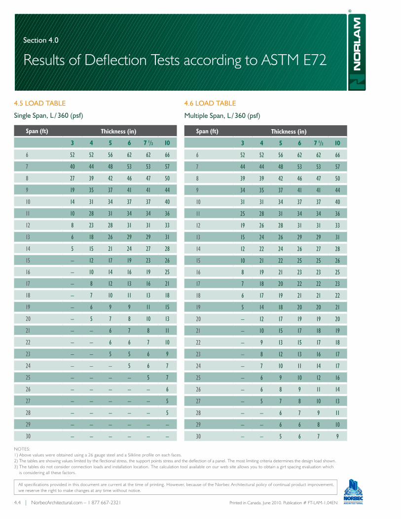
4.6 Load TabLe
Multiple Span, L / 360 (psf)
Span (ft) Thickness (in)
3 4 5 6 7 1/2 10
6 52 52 56 62 62 66
7 44 44 48 53 53 57
8 39 39 42 46 47 50
9 34 35 37 41 41 44
10 31 31 34 37 37 40
11 25 28 31 34 34 36
12 19 26 28 31 31 33
13 15 24 26 29 29 31
14 12 22 24 26 27 28
15 10 21 22 25 25 26
16 8 19 21 23 23 25
17 7 18 20 22 22 23
18 6 17 19 21 21 22
19 5 14 18 20 20 21
20 – 12 17 19 19 20
21 – 10 15 17 18 19
22 – 9 13 15 17 18
23 – 8 12 13 16 17
24 – 7 10 11 14 17
25 – 6 9 10 12 16
26 – 6 8 9 11 14
27 – 5 7 8 10 13
28 – – 6 7 9 11
29 – – 6 6 8 10
30 – – 5 6 7 9
Section 4.0
Results of Deflection Tests according to ASTM E72
4.4 | NorbecArchitectural.com – 1 877 667-2321 Printed in Canada. June 2010. Publication # FT-LAM-1,04EN
All specifications provided in this document are current at the time of printing. However, because of the Norbec Architectural policy of continual product improvement, we reserve the right to make changes at any time without notice.
NOTES:1) Above values were obtained using a 26 gauge steel and a Silkline profile on each faces.2) The tables are showing values limited by the flectional stress, the support points stress and the deflection of a panel. The most limiting criteria determines the design load shown.3) The tables do not consider connection loads and installation location. The calculation tool available on our web site allows you to obtain a girt spacing evaluation which
is considering all these factors.