technical data - link-belt cranes · swing up roof window with windshield wiper and washer sliding...
TRANSCRIPT

15813 (supersedes 5774)-0818-T5
75RTLink‐Belt Cranes
Technical DataSpecifications & Capacities
Telescopic Boom Rough Terrain Crane75 US ton
70 metric ton
CAUTION: This material is supplied for
reference use only. Operator must refer to
in-cab Crane Rating Manual and Operator's
Manual to determine allowable crane lifting
capacities and assembly and operating
procedures.

5813 (supersedes 5774)-0818-T5
75RT Link‐Belt Cranes

5813 (supersedes 5774)-0818-T5
75RTLink‐Belt Cranes
Table Of Contents
Boom, Attachments, and Upper Structure 1. . . . . . . . . . . . . . . . . . . . . . . . . . . . . . . . . . . . . . . . . . . . . . . . . . . .
Boom 1. . . . . . . . . . . . . . . . . . . . . . . . . . . . . . . . . . . . . . . . . . . . . . . . . . . . . . . . . . . . . . . . . . . . . . . . . . . . . . . . . . . .
Boom 1. . . . . . . . . . . . . . . . . . . . . . . . . . . . . . . . . . . . . . . . . . . . . . . . . . . . . . . . . . . . . . . . . . . . . . . . . . . . . . . . . . .
Boom Wear Pads 1. . . . . . . . . . . . . . . . . . . . . . . . . . . . . . . . . . . . . . . . . . . . . . . . . . . . . . . . . . . . . . . . . . . . . . . . .
Boom Head 1. . . . . . . . . . . . . . . . . . . . . . . . . . . . . . . . . . . . . . . . . . . . . . . . . . . . . . . . . . . . . . . . . . . . . . . . . . . . .
Boom Elevation 1. . . . . . . . . . . . . . . . . . . . . . . . . . . . . . . . . . . . . . . . . . . . . . . . . . . . . . . . . . . . . . . . . . . . . . . . . .
Auxiliary Lifting Sheave - Optional 1. . . . . . . . . . . . . . . . . . . . . . . . . . . . . . . . . . . . . . . . . . . . . . . . . . . . . . . . .
Hook Blocks and Balls - Optional 1. . . . . . . . . . . . . . . . . . . . . . . . . . . . . . . . . . . . . . . . . . . . . . . . . . . . . . . . . .
Fly - Optional 1. . . . . . . . . . . . . . . . . . . . . . . . . . . . . . . . . . . . . . . . . . . . . . . . . . . . . . . . . . . . . . . . . . . . . . . . . . .
Operator's Cab and Controls 1. . . . . . . . . . . . . . . . . . . . . . . . . . . . . . . . . . . . . . . . . . . . . . . . . . . . . . . . . . . . . . . .
Swing 3. . . . . . . . . . . . . . . . . . . . . . . . . . . . . . . . . . . . . . . . . . . . . . . . . . . . . . . . . . . . . . . . . . . . . . . . . . . . . . . . . . . .
Electrical 3. . . . . . . . . . . . . . . . . . . . . . . . . . . . . . . . . . . . . . . . . . . . . . . . . . . . . . . . . . . . . . . . . . . . . . . . . . . . . . . . .
Load Hoist System 3. . . . . . . . . . . . . . . . . . . . . . . . . . . . . . . . . . . . . . . . . . . . . . . . . . . . . . . . . . . . . . . . . . . . . . . . .
Load Hoist Performance 3. . . . . . . . . . . . . . . . . . . . . . . . . . . . . . . . . . . . . . . . . . . . . . . . . . . . . . . . . . . . . . . . . . .
Main and Optional Auxiliary Winches 3. . . . . . . . . . . . . . . . . . . . . . . . . . . . . . . . . . . . . . . . . . . . . . . . . . . . . . .
Hydraulic System 3. . . . . . . . . . . . . . . . . . . . . . . . . . . . . . . . . . . . . . . . . . . . . . . . . . . . . . . . . . . . . . . . . . . . . . . . . .
Counterweight 3. . . . . . . . . . . . . . . . . . . . . . . . . . . . . . . . . . . . . . . . . . . . . . . . . . . . . . . . . . . . . . . . . . . . . . . . . . . .
Carrier 4. . . . . . . . . . . . . . . . . . . . . . . . . . . . . . . . . . . . . . . . . . . . . . . . . . . . . . . . . . . . . . . . . . . . . . . . . . . . . . . . . . . .
General 4. . . . . . . . . . . . . . . . . . . . . . . . . . . . . . . . . . . . . . . . . . . . . . . . . . . . . . . . . . . . . . . . . . . . . . . . . . . . . . . . . . .
Outriggers 4. . . . . . . . . . . . . . . . . . . . . . . . . . . . . . . . . . . . . . . . . . . . . . . . . . . . . . . . . . . . . . . . . . . . . . . . . . . . . . . .
Steering and Axles 4. . . . . . . . . . . . . . . . . . . . . . . . . . . . . . . . . . . . . . . . . . . . . . . . . . . . . . . . . . . . . . . . . . . . . . . . .
Suspension 4. . . . . . . . . . . . . . . . . . . . . . . . . . . . . . . . . . . . . . . . . . . . . . . . . . . . . . . . . . . . . . . . . . . . . . . . . . . . . . .
Tires and Wheels 4. . . . . . . . . . . . . . . . . . . . . . . . . . . . . . . . . . . . . . . . . . . . . . . . . . . . . . . . . . . . . . . . . . . . . . . . . .
Brakes 4. . . . . . . . . . . . . . . . . . . . . . . . . . . . . . . . . . . . . . . . . . . . . . . . . . . . . . . . . . . . . . . . . . . . . . . . . . . . . . . . . . .
Electrical 4. . . . . . . . . . . . . . . . . . . . . . . . . . . . . . . . . . . . . . . . . . . . . . . . . . . . . . . . . . . . . . . . . . . . . . . . . . . . . . . . .
Engine 4. . . . . . . . . . . . . . . . . . . . . . . . . . . . . . . . . . . . . . . . . . . . . . . . . . . . . . . . . . . . . . . . . . . . . . . . . . . . . . . . . . .
Transmission 4. . . . . . . . . . . . . . . . . . . . . . . . . . . . . . . . . . . . . . . . . . . . . . . . . . . . . . . . . . . . . . . . . . . . . . . . . . . . . .
Fuel Tank 5. . . . . . . . . . . . . . . . . . . . . . . . . . . . . . . . . . . . . . . . . . . . . . . . . . . . . . . . . . . . . . . . . . . . . . . . . . . . . . . . .
Hydraulic System 5. . . . . . . . . . . . . . . . . . . . . . . . . . . . . . . . . . . . . . . . . . . . . . . . . . . . . . . . . . . . . . . . . . . . . . . . . .
Pump Drive 5. . . . . . . . . . . . . . . . . . . . . . . . . . . . . . . . . . . . . . . . . . . . . . . . . . . . . . . . . . . . . . . . . . . . . . . . . . . . . . .
Maximum Speed 5. . . . . . . . . . . . . . . . . . . . . . . . . . . . . . . . . . . . . . . . . . . . . . . . . . . . . . . . . . . . . . . . . . . . . . . . . .
Paint 5. . . . . . . . . . . . . . . . . . . . . . . . . . . . . . . . . . . . . . . . . . . . . . . . . . . . . . . . . . . . . . . . . . . . . . . . . . . . . . . . . . . . .
Additional Equipment Options 5. . . . . . . . . . . . . . . . . . . . . . . . . . . . . . . . . . . . . . . . . . . . . . . . . . . . . . . . . . . . . . .
Gradeability 5. . . . . . . . . . . . . . . . . . . . . . . . . . . . . . . . . . . . . . . . . . . . . . . . . . . . . . . . . . . . . . . . . . . . . . . . . . . . . . .
Axle Loads 6. . . . . . . . . . . . . . . . . . . . . . . . . . . . . . . . . . . . . . . . . . . . . . . . . . . . . . . . . . . . . . . . . . . . . . . . . . . . . . . .
General Dimensions 7. . . . . . . . . . . . . . . . . . . . . . . . . . . . . . . . . . . . . . . . . . . . . . . . . . . . . . . . . . . . . . . . . . . . . . . .
General Dimensions 8. . . . . . . . . . . . . . . . . . . . . . . . . . . . . . . . . . . . . . . . . . . . . . . . . . . . . . . . . . . . . . . . . . . . . . . .
Working Range Diagram 9. . . . . . . . . . . . . . . . . . . . . . . . . . . . . . . . . . . . . . . . . . . . . . . . . . . . . . . . . . . . . . . . . . . .
Boom Extend Modes 10. . . . . . . . . . . . . . . . . . . . . . . . . . . . . . . . . . . . . . . . . . . . . . . . . . . . . . . . . . . . . . . . . . . . . . .
Main Boom Lift Capacity Charts - Imperial 11. . . . . . . . . . . . . . . . . . . . . . . . . . . . . . . . . . . . . . . . . . . . . . . . . .
14,500lb Counterweight - Fully Extended Outriggers - 360° Rotation 11. . . . . . . . . . . . . . . . . . . . . . . . . . .
14,500lb Counterweight On Tires - Stationary - Boom Centered Over The Front Between Tire Tracks 12
14,500lb Counterweight On Tires - Boom Centered Over The Front Pick and Carry - Creep 13. . . . . . .
14,500lb Counterweight On Tires - Stationary - 360° Rotation 13. . . . . . . . . . . . . . . . . . . . . . . . . . . . . . . . .

5813 (supersedes 5774)-0818-T5
75RT Link‐Belt Cranes
Fly Attachment Lift Capacity Charts - Optional 14. . . . . . . . . . . . . . . . . . . . . . . . . . . . . . . . . . . . . . . . . . . . . . .
14,500lb Counterweight - Fully Extended Outriggers - 360° Rotation 14. . . . . . . . . . . . . . . . . . . . . . . . . . .
Main Boom + 10 ft Manual Offset Fly (2°, 15°, 30° & 45° Offsets) 14. . . . . . . . . . . . . . . . . . . . . . . . . . . . . .
14,500lb Counterweight - Fully Extended Outriggers - 360° Rotation 15. . . . . . . . . . . . . . . . . . . . . . . . . . .
35 ft Manual Offset Fly 15. . . . . . . . . . . . . . . . . . . . . . . . . . . . . . . . . . . . . . . . . . . . . . . . . . . . . . . . . . . . . . . . . . . .
58 ft Manual Offset Fly 15. . . . . . . . . . . . . . . . . . . . . . . . . . . . . . . . . . . . . . . . . . . . . . . . . . . . . . . . . . . . . . . . . . . .
Main Boom Lift Capacity Charts - 85% - Metric 16. . . . . . . . . . . . . . . . . . . . . . . . . . . . . . . . . . . . . . . . . . . . .
6.6t Counterweight - Fully Extended Outriggers - 360° Rotation 16. . . . . . . . . . . . . . . . . . . . . . . . . . . . . . .
6.6t Counterweight On Tires - Stationary - Boom Centered Over The Front Between Tire Tracks 17. . .
6.6t Counterweight On Tires - Boom Centered Over The Front Pick and Carry - Creep 18. . . . . . . . . . .
6.6t Counterweight On Tires - Stationary - 360° Rotation 18. . . . . . . . . . . . . . . . . . . . . . . . . . . . . . . . . . . . . .
Fly Attachment Lift Capacity Charts - 85% - Optional 19. . . . . . . . . . . . . . . . . . . . . . . . . . . . . . . . . . . . . . . .
6.6t Counterweight - Fully Extended Outriggers - 360° Rotation 19. . . . . . . . . . . . . . . . . . . . . . . . . . . . . . .
Main Boom + 3.0m Manual Offset Fly (2°, 15°, 30° & 45° Offsets) 19. . . . . . . . . . . . . . . . . . . . . . . . . . . . .
6.6t Counterweight - Fully Extended Outriggers - 360° Rotation 20. . . . . . . . . . . . . . . . . . . . . . . . . . . . . . .
10.7m Manual Offset Fly 20. . . . . . . . . . . . . . . . . . . . . . . . . . . . . . . . . . . . . . . . . . . . . . . . . . . . . . . . . . . . . . . . . .
17.7m Manual Offset Fly 20. . . . . . . . . . . . . . . . . . . . . . . . . . . . . . . . . . . . . . . . . . . . . . . . . . . . . . . . . . . . . . . . . .
Main Boom Lift Capacity Charts - 75% - Metric 21. . . . . . . . . . . . . . . . . . . . . . . . . . . . . . . . . . . . . . . . . . . . .
6.6t Counterweight - Fully Extended Outriggers - 360° Rotation 21. . . . . . . . . . . . . . . . . . . . . . . . . . . . . . .
6.6t Counterweight On Tires - Stationary - Boom Centered Over The Front Between Tire Tracks 22. . .
6.6t Counterweight On Tires - Boom Centered Over The Front Pick and Carry - Creep 23. . . . . . . . . . .
6.6t Counterweight On Tires - Stationary - 360° Rotation 23. . . . . . . . . . . . . . . . . . . . . . . . . . . . . . . . . . . . . .
Fly Attachment Lift Capacity Charts - 75% - Optional 24. . . . . . . . . . . . . . . . . . . . . . . . . . . . . . . . . . . . . . . .
6.6t Counterweight - Fully Extended Outriggers - 360° Rotation 24. . . . . . . . . . . . . . . . . . . . . . . . . . . . . . .
Main Boom + 3.0m Manual Offset Fly (2°, 15°, 30° & 45° Offsets) 24. . . . . . . . . . . . . . . . . . . . . . . . . . . . .
6.6t Counterweight - Fully Extended Outriggers - 360° Rotation 25. . . . . . . . . . . . . . . . . . . . . . . . . . . . . . .
10.7m Manual Offset Fly 25. . . . . . . . . . . . . . . . . . . . . . . . . . . . . . . . . . . . . . . . . . . . . . . . . . . . . . . . . . . . . . . . . .
17.7m Manual Offset Fly 25. . . . . . . . . . . . . . . . . . . . . . . . . . . . . . . . . . . . . . . . . . . . . . . . . . . . . . . . . . . . . . . . . .

15813 (supersedes 5774)-0818-T5
75RTLink‐Belt Cranes
Boom, Attachments, and Upper Structure� BoomDesign - Five section, formed construction of extra hightensile steel consisting of one base section and fourtelescoping sections.
Boom� 38-142 ft (11.58-43.28m) five section full power boom� Two boom extension modes controlled from the
operator's cab provides superior capacities by varyingthe extension of the telescoping sections. EM1 modeextends sections T2, T3, and T4 proportionally to a 116 ft(35.36m) boom length. Next section T1 extends to reachfull 142 ft (43.28m) boom length. EM2 mode extends theT1 section to reach a 64 ft (19.51m) boom length. Nextsections T2, T3, and T4 extend proportionally to reachthe full 142 ft (43.28m) boom length.
� Mechanical boom angle indicator� Maximum tip height is 151.4 ft (22.4m).
Boom Wear Pads� Wear pads with Teflon inserts that self-lubricate the
boom sections� Bottom wear pads are universal for all boom sections� Top wear pads are universal for all boom sections
Boom Head� Five 16.5 in (41.9cm) root diameter nylon sheaves to
handle up to ten parts of line� Easily removable wire rope guards� Rope dead end lugs on each side of the boom head� Boom head is designed for quick-reeve of the hook
block� Wind speed indicator� Aviation obstruction solar marking light and flag -
optional
Boom Elevation� One double acting hydraulic cylinder with integral
holding valve� Boom elevation: -3° to 80°
Auxiliary Lifting Sheave - Optional� Single 16.5 in (41.9cm) root diameter nylon sheave� Easily removable wire rope guards� Does not affect erection of the fly or use of the main head
sheaves
Hook Blocks and Balls - Optional� 27 ton (25mt) 1 sheave quick-reeve hook block with
safety latch� 60 ton (55mt) 3 sheave quick-reeve hook block with
safety latch� 88 ton (80mt) 5 sheave quick-reeve hook block with
safety latch� 10 ton (9mt) swivel and non-swivel hook balls with
safety latch
Fly - Optional� 10 ft (3.0m) one piece lattice fly, stowable, offsettable to
2°, 15°, 30°, and 45°. Maximum tip height is 160 ft(48.8m).
� 35-58 ft (10.7-17.7m) two piece bi-fold lattice fly,stowable, offsettable to 2°, 15°, 30°, and 45°. Maximumtip height is 208.7 ft (63.6m).
� 10-35-58 ft (3.0-10.7-17.7m) three piece bi-foldlattice fly, stowable, offsettable to 2°, 15°, 30°, and 45°.Maximum tip height is 208.7 ft (63.6m).
� Operator's Cab and ControlsEnvironmental Cab - Fully enclosed, one person cab oftubular and sheet steel structure with formed plastic interiorpanels.Equipped with:� Tinted and tempered glass windows� Extra-large fixed front window with time delayed
windshield wiper and washer� Swing up roof window with windshield wiper and washer� Sliding left side door with large fixed window� Sliding right side window and pop-out rear window for
ventilation� Six way adjustable, cushioned seat with seat belt and
storage compartment� Diesel fired warm-water heater with ten air ducts for front
windshield defroster and cab floor� Air Conditioning - Integral with cab heating system
utilizing the same ventilation outlets and automatictemperature control (ATC)
� Adjustable sun screen� Dome lights with red nighttime reading LED's� Cup holder� Fire extinguisher� Two position travel swing lock� AM/FM radio
Engine Dependent Warm-Water Heater - Optional -With air ducts for front windshield defroster and cab floor

2 5813 (supersedes 5774)-0818-T5
75RT Link‐Belt Cranes
Steering Column - Pedestal type with tilt and telescopefunctions for operator comfort. Column includes thefollowing controls and indicators:� Horn button� Turn signal switch� Driving light switch� Transmission gear selector� Transmission Direction Switches� Travel park brake� 2/4 wheel drive/range selector� Hazard flasherArmrest Controls - Two dual axis electronic joystickcontrollers or optional single axis electronic controllers for:� Swing� Boom hoist� Main (rear) winch� Auxiliary (front) winch - optional� Winch high/low speed switch(es)� Warning horn button� Swing park brake switch� Engine throttle lock switch� Engine set/resume switch� Cab tilt� Telescope overrideOutrigger Controls - Hand held control box with umbilicalcord gives the operator the freedom to view operation whilesetting the outriggers.
Foot Controls� Boom telescope� Swing brake� Engine throttle� Service brakeUpper Right Console - Controls and indicators for:� Engine ignition � Radio� Engine stop � DRI on/off selection� Function lockout � HVAC controller� Front windshield wiper � 360 swing lock - optional
and washer � Boom floodlights - optional� Cab lights and upper � Rotating beacon/Strobe
frame lights - optional light� Horn � Top hatch wiper washer� Dome light with switch � Winch(es) disable� E-stop switch � Engine indicator gauge
Rear Right Side Panel� 12V accessory outlet (10amp)� USB charge portCamera Display - Located on the right A-post with anadjustable mount� Displays right side of upper� Displays main and auxiliary winches� Displays rear viewDiagnostic Center - Located on the right rear wall behindthe seat.� Engine diagnostic� RCL CANBUS diagnostic� Boom CANBUS diagnostic� Outrigger CANBUS diagnostic
Fuse & Relay Panel - Located on the left rear wall behindthe seat.
LinkBelt Pulse 2.0 – The LinkBelt inhouse designed,total crane operating system that utilizes a 10 in touchscreen color display with integrated RCL and engine data,advanced diagnostics and systems monitoring, Wi–Ficapable for remote software updates, operatorcustomizable, and a readout and operator interface for thefollowing systems:� Rated capacity limiter – LCD graphic audio – visual
warning system integrated into the dash with anti – twoblock and function limiter. Operating data includes:� RCL controller USB diagnostic� Crane configuration� Boom length and angle� Boom head height� Allowed load and % of allowed load� RCL light bar� Boom angle� Radius of load� Actual load� Wind speed� Highlighted unit of measurement on working screen� Telescope operation displayed in real time� Steer mode selector� Outrigger position sensing� Drum Rotation direction indication� Third wrap indicator - optional� Diagnostics� Operator settable alarms (include):
� Maximum and minimum boom angles� Maximum tip height� Maximum boom length� Swing left/right positions� Operator defined area (imaginary plane)
� Cab Instrumentation� Tachometer � Swing park brake light� Engine water temperature � Engine speed� Fuel level � Engine oil pressure� Hydraulic oil temperature � Battery voltage� Stop engine � Fuel rate (gal/hr)� Check engine � Engine load� Wait to start � Engine Diagnostics� Diesel exhaust fluid (DEF) level(1)
� Engine air filter high restriction light� Regeneration light(1)
� Regeneration inhibit switch(1)
� Regeneration initiate switch(1)
� High exhaust temperature light(1)
� Regeneration disabled light(1)
(1) (Tier 4f / Stage IV engine only)
� Telematics – Cellular based data logging and monitoringsystem that provides:� Location and operational settings� Routine maintenance� Crane and engine monitoring� Diagnostic and fault codes

35813 (supersedes 5774)-0818-T5
75RTLink‐Belt Cranes
Internal RCL Light Bar - Visually informs the operatorwhen crane is approaching maximum load capacity with aseries of green, yellow, and red lights.
Integrated Third Wrap Indicator - Optional - Link‐BeltPulse 2.0 color display visually and audibly warns theoperator when the wire rope is on the first/bottom layer andwhen the wire rope is down to the last three wraps.Integrated Third Wrap Function Kickout - Optional -Link‐Belt Pulse 2.0 color display visually and audibly warnsthe operator when the wire rope is on the first/bottom layerand provides a function kickout when the wire rope is downto the last three wraps.External RCL Light Bar - Optional - Visually informs theground crew when crane is approaching maximum loadcapacity with a series of green, yellow, and red lights.
� SwingMotor/Planetary - Bi-directional hydraulic swing motormounted to a planetary reducer for 360° continuoussmooth swing at 1.9 rpmSwing Park Brake - 360°, electric over hydraulic, (springapplied/hydraulic released) multi-disc brake mounted on
the speed reducer. Operated by a switch in the operator'scab.
Swing Brake - 360°, foot operated, speed reducingsystem with disc brake hold featureSwing Lock - Two-position swing lock (boom over frontor rear) operated from the operator's cab360° Positive Swing Lock - Optional - Meets New YorkCity requirement
� ElectricalSwing Alarm - Audio warning device signals when theupper is swinging.Lights� Two LED working lights on front of the cab� Two amber strobe lights at rear of the upper frame� One LED working light on top of cab - optional� LED Boom floodlight - Single - optional� LED Boom floodlight - Dual - optional� LED Boom floodlight - High intensity remote controlled
- optional� LED Frame work lights - right front, left rear, and work
platform - optional
� Load Hoist SystemLoad Hoist Performance
Main (Rear) and Auxiliary (Front) Winches - 3/4 in (19mm) Rope
Maximum Line Pull Normal Line Speed High Line Speed Layer Total
Layer lb kN ft/min m/min ft/min m/min ft m ft m
1 18,603 82.8 168 51.2 359 109.4 114 34.7 114 34.7
2 17,103 76.08 183 55.8 391 119.2 124 37.8 238 72.5
3 15,827 70.4 198 60.4 422 128.6 134 40.8 372 113.4
4 14,728 65.51 212 64.6 454 138.4 144 43.9 516 157.3
5 13,772 61.26 227 69.2 485 147.8 154 46.9 670 204.2
Wire Rope ApplicationDiameter
Type
MaximumPermissible Load
in mm lb kg
Main (Rear)Winch
Standard 3/4 19 37x7 rotation resistant - right lang lay (Type KC) 16,000 7 257.5
Optional 3/4 19 35x7 rotation resistant - right lang lay (Type CC) 17,160 7 783.6
Auxiliary (Front)Winch
Standard 3/4 19 37x7 rotation resistant - right lang lay (Type KC) 16,000 7 257.5
Optional 3/4 19 35x7 rotation resistant - right lang lay (Type CC) 17,160 7 783.6
Main and Optional Auxiliary Winches� Axial piston, full and half displacement (2-speed) motors
driven through planetary reduction unit for positivecontrol under all load conditions
� Grooved lagging� Power up/down mode of operation� Drum rotation indicator(s)� Drum diameter: 16 in (40.6cm)� Rope length:� Front: 500 ft (152.4m)� Rear: 600 ft (182.9m)
� Maximum rope storage: 670 ft (204.2m)� Terminator style socket and wedge� Encoders for reading rope payout� Hoist drum cable followers - optional
� Hydraulic SystemCounterbalance Valves - All hoist motors, boom extendcylinders, and boom hoist cylinders are equipped withcounterbalance valves to control load lowering. Thisprevents accidental load drop when hydraulic power issuddenly reduced.
� CounterweightTotal of 14,500 lb (6.6t) counterweight pinned to the upperwith capacities for:� 0 lb (0t) counterweight*� 14,500 lb (6.6t) counterweight
Hydraulic counterweight removal - optional - activatedby a hand-held controller with enough cable to access thepins on each side of the counterweights.
* Travel speed limited to 5 mph.

4 5813 (supersedes 5774)-0818-T5
75RT Link‐Belt Cranes
Carrier
� General� 10 ft 7 in (3.22m) wide� 14 ft 7 in (4.45m) wheelbase (centerline of first axle to
centerline of second axle)
Frame - Box-type, torsion resistant, welded constructionmade of high tensile steel. Equipped with front and reartowing and tie-down lugs, tow connections, and accessladders.
� OutriggersBoxes - Two double box, front and rear welded to carrierframe
Beams and Jacks - Four single stage beams that arehydraulically controlled from the operator's cab withintegral check valves.
V-CALC - Variable confined area lifting capabilities thatare incorporated directly into the Pulse 2.0 display allowingmultiple outrigger configurations of fully extended,intermediate, and fully retracted selectable in pairs, with liveon screen working radii, utilizing 360° charts, and swingarrest.
Pontoons - Four lightweight, quick release, 24 in (61cm),steel pontoons with contact area of 452 in2 (2 916cm2) canbe stored for road travel in storage racks on the carrier.
Main Jack Reaction - 93,000 lb (42 186kg) force and206 psi (1 420kPa) ground bearing pressure.
� Steering and AxlesSteering - Four independent modes consisting of twowheel front, two wheel rear, four wheel, and crab. Eachmode is controlled from the steering wheel and is selectedby a switch in the operator's cab.
Drive - Two modes: 4 x 2 and 4 x 4 for off highway travelAxle 1 - Steered, non-driven for 4 x 2 and steered, drivenfor 4 x 4Axle 2 - Steered, driven
� SuspensionFront - Rigid mount to the carrier frame
Rear - The rear axle is suspended on the oscillationcylinders with motion of the axle controlled by a four barlinkage system. The oscillation cylinders lockout when theupper structure rotates 2.5° past centerline.� Hydro-gas rear suspension - optional
� Tires and WheelsFront and Rear - Four (single) 26.5 x 25-32 ply rating,earthmover type tires on steel disc wheels� Spare tires and wheels - optional
� BrakesService - Full hydraulic, dual circuit, disc type brakes onall wheel ends
Parking/Emergency - Spring applied type, acting on frontaxle
� ElectricalTwo batteries provide 24 volt starting and operation
Lights� All lights are LED.� Front lighting includes two main headlights, outrigger
lights, and two parking/directional indicators.� Side lighting includes two parking/directional indicators
per side.� Rear lighting includes two parking/directional indicators,
two parking/brake lights, and two reversing lights.� Other equipment includes hazard/warning system, cab
light, instrument panel light, and signal horn.
� Engine
Specification Cummins QSB
Numbers ofCylinders
6 6
Cycle 4 4
EmissionsCompliance Level:
Tier 4f/Stage IV(1) Tier 3/Stage IIIA(2)
Bore and Stroke:inch (mm)
4.21 x 4.88 (107 x124)
4.21 x 4.88 (107 x124)
Piston Displacement:in3 (L)
408 (6.7) 408 (6.7)
Max. Brake Horsepower: hp (kW)
270 (201) @ 2,000rpm
270 (201) @ 2,000rpm
260 (194) @ 2,200rpm
260 (194) @ 2,200rpm
Peak Torque: ft lb(Nm)
730 (990) @ 1,500rpm
730 (990) @ 1,500rpm
Electric/startingsystems: volts
24/24 24/24
Alternator: amps 140 140
Crankcase Capacity:qt (L)
15 (14.2) 15 (14.2)
� Water/fuel separator w/ heater and water in fuel (WIF) sensor
� 120-volt block heater - Tier 4f / Stage IV
� 220-volt block heater - Tier 3 / Stage IIIA
� Grid heater - 112 amp
� Mechanically driven, variable speed, engine controlled, viscous fanclutch
� (1) Can only be sold and/or operated where Tier 4f and Stage IVoff-highway emission standards are accepted.
� (2) Can only be sold and/or operated where Tier 3 and Stage IIIAoff-highway emission standards are accepted.
� TransmissionPowershift - Three speed with high/low range for 6forward and 6 reverse gears. Front axle disconnect for twoor four wheel drive. Front axle disconnects in high range.

55813 (supersedes 5774)-0818-T5
75RTLink‐Belt Cranes
� Fuel TankOne 75 gallon (283.9L) capacity tank
Diesel Exhaust Fluid (DEF) tank(1)
� One 5 gal (18.9L) capacity tank
(1) (Tier 4f / Stage IV engine only)
� Hydraulic SystemAll functions are hydraulically powered allowing positiveprecise control with independent or simultaneous operationof all functions.
Main Pumps� One variable displacement, load sense, piston pump with
anti-stall for the front/rear winches, boom hoist, andtelescope circuits.
� One two section fixed displacement gear pump for thepower steering/swing and for the servicebrakes/outriggers/oscillation/counterweights.
� One single section gear pump for the hydraulic oil coolerfan drive.
� Combined pump capacity of 127 gpm (480.7Lpm)
Hydraulic Reservoir - 173 gal (654.9L) capacity equippedwith sight level gauge. Diffusers built in for deaeration.
Filtration - One 5 micron, full flow line filter in the controlcircuit. All oil is filtered prior to return to reservoir.Accessible for easy filter replacement.
Hydraulic Oil Coolers - One carrier mounted coolerremoves heat from the hydraulic oil. Remote mounted onright side of the carrier.
� Pump DriveAll pumps are mounted on the transmission andmechanically driven by the diesel engine.
� Maximum Speed20.8 mph (33.47 km/h)
� PaintEntire machine is prepainted and oven baked withHighsolid Paint (2 part epoxy/polyester) and/or (2 partepoxy primer/2 part polyurethane top coat). StandardLinkBelt Red, LinkBelt Gray, and Gloss Black colors apply.
� Additional Equipment Options� Spark arrestor - optional� Engine air intake shutoff valve - optional
� Gradeability
CounterweightAscending Descending Side
Degrees % Grade Degrees % Grade Degrees % Grade
0 16.0 29% 6.0 11%5.0 9%
14,500 lbs (6.6t) 14.0 25% 14.0 25%
6 5813 (supersedes 5774)-0818-T5
75RT Link‐Belt Cranes
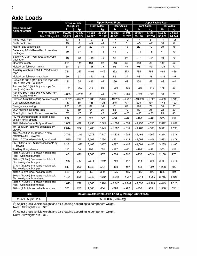
Axle Loads
Base crane withfull tank of fuel
Gross VehicleWeight (1)
Upper Facing Front Upper Facing Rear
Front Axles Rear Axles Front Axles Rear Axles
lb kg lb kg lb kg lb kg lb kg
Tier 4f / Stage IV 92,996 42 182 44,682 20 268 48,313 21 915 39,354 17 851 53,642 24 332
Tier 3 / Stage IIIA 92,427 41 924 44,527 20 197 47,901 21 727 39,198 17 780 53,229 24 144
Pintle hook, front 13 6 17 8 -4 -2 17 8 -4 -2
Pintle hook, rear 13 6 -5 -2 18 8 -5 -2 18 8
Hydro-gas suspension 61 28 22 10 39 18 22 10 39 18
Battery w/ AGM (Use with cold weatherpackage)
30 14 -11 -5 41 19 -11 -5 41 19
Battery w/ Cap-AGM (Use with Arcticpackage)
43 20 -16 -7 59 27 -16 -7 59 27
Operator in cab 250 113 134 61 116 53 103 47 147 67
Hoist drum follower - main 68 31 -28 13 96 44 93 42 -25 11
Auxiliary winch with 500 ft (152.4m) wirerope
721 327 -101 -46 822 373 785 785 -64 -29
Hoist drum follower - auxiliary 69 31 -17 -8 86 39 83 38 -14 -6
Substitute 500 ft (152.4m) wire rope with600 ft (182.9m) - auxiliary
121 55 -15 -7 136 62 130 59 -9 -4
Remove 600 ft (182.9m) wire rope fromrear (main) winch
-744 -337 216 98 -960 -435 -922 -418 178 81
Remove 500 ft (152.4m) wire rope fromfront (auxiliary) winch
-623 -283 88 40 -711 -323 -679 -308 56 25
Remove 14,500 lbs (6.6t) counterweight -14,520 -6 586 5,235 2 375 -19,755 -8 961 -19,009 -8 622 4,489 2 036
Counterweight Removal 187 85 -58 -26 245 111 235 107 -48 -22
Emergency steering 220 100 39 18 181 82 170 77 50 23
360° mechanical swing lock 152 69 64 29 88 40 80 36 72 33
Floodlight to front of boom base section 37 17 93 42 -56 -25 -58 -26 95 43
Fly mounting brackets to boom basesection for fly options
232 105 323 147 -91 -41 -103 -47 335 152
10 ft (3.0m) offsettable fly - stowed 1,062 482 2,458 1 115 -1,396 -633 -1,450 -658 2,512 1 139
10-35 ft (3.0-10.67m) offsettable fly -stowed
2,044 927 3,406 1 545 -1,362 -618 -1,467 -665 3,511 1 593
10-35-58 ft (3.0-10.67-17.68m)offsettable fly - stowed
2,745 1 245 4,073 1 847 -1,328 -602 -1,469 -666 4,214 1 911
35 ft (10.67m) offsettable fly - stowed 1,580 717 2,501 1 134 -921 -418 -1,002 -454 2,582 1 171
35-58 ft (10.67-17.68m) offsettable fly- stowed
2,281 1 035 3,168 1 437 -887 -402 -1,004 -455 3,285 1 490
Auxiliary lifting sheave 110 50 297 135 -187 -85 -193 -88 303 137
60 ton (54.4mt) 3-sheave hook blockFlexi-weight at bumper
1,401 636 2,065 937 -664 -301 -737 -334 2,138 970
88 ton (79.8mt) 5-sheave hook blockFlexi-weight at bumper
1,613 732 2,378 1 079 -765 -347 -848 -385 2,461 1 116
27 ton (24.5mt) 1-sheave hook blockFlexi-weight at bumper
843 382 1,243 564 -400 -181 -443 -201 1,286 583
10 ton (9.1mt) hook ball at bumper 580 263 855 388 -275 -125 -305 -138 885 401
60 ton (54.4mt) 3-sheave hook blockFlexi-weight at boom head
1,401 636 3,643 1 652 -2,242 -1 017 -2,314 -1 050 3,715 1 685
88 ton (79.8mt) 5-sheave hook blockFlexi-weight at boom head
1,613 732 4,360 1 978 -2,747 -1 246 -2,830 -1 284 4,443 2 015
10 ton (9.1mt) hook ball at boom head 580 263 1,508 684 -928 -421 -958 435 1,538 698
Tire Maximum Allowable Axle Load @ 20 mph (32.2km/h)
26.5 x 25 (32-PR) 55,000 lb (24 948kg)
(1) Adjust gross vehicle weight and axle loading according to component weight.Note: All weights are ±3%.
(1) Adjust gross vehicle weight and axle loading according to component weight.Note: All weights are ±3%.

75813 (supersedes 5774)-0818-T5
75RTLink‐Belt Cranes
General DimensionsTier 4f / Stage IV
12' 8.88”(3.9m)
47' 2.41”(14.4m)
7' 0”(2.1m)
38' 0.73”(11.6m)
20°
Not To Scale
C of RotationL
C of RotationL
Turning Radius - Front Wheel (4x2) Steering English Metric
Wall to wall over carrier 43' 2” 13.2m
Wall to wall over boom attachment 53' 3” 16.2m
Curb to curb 41' 6” 12.6m
Centerline of tire 40' 0” 12.2m
Tail Swing English Metric
With counterweight 13' 7.98” 4.17m
Turning Radius - All Wheel (4x4) Steering English Metric
Wall to wall over carrier 26' 6” 8.1m
Wall to wall over boom attachment 38' 0” 11.6m
Curb to curb 24' 10” 7.6m
Centerline of tire 23' 6” 7.2m
1' 2.11”(0.4m)
12' 2.32”(3.7m)
23°
7' 8”(2.3m)
6' 11”(2.1m)
13' 6.81”(4.1m)
45' 5.87”(13.9m)
5' 8.64”(1.7m)
10' 2”(3.1m)
13.21”(0.3m)
23.03”(0.6m)
11' 6.88”(3.5m)
10' 6.98”(3.2m)
19' 9.3”(6.0m)
26' 0.03”(7.9m)
2' 6.87”(0.8m)
1' 2.52”(0.4m)
Without counterweight 13' 0.73” 4.0m
1' 6.23”(0.5m)
10.56”(0.3m)
13' 6.81”(4.1m)
8' 2.53”(2.5m)
7' 6.57”(2.3m)

8 5813 (supersedes 5774)-0818-T5
75RT Link‐Belt Cranes
General DimensionsTier 3 / Stage IIIA
Turning Radius - Front Wheel (4x2) Steering English Metric
Wall to wall over carrier 43' 2” 13.2m
Wall to wall over boom attachment 53' 3” 16.2m
Curb to curb 41' 6” 12.6m
Centerline of tire 40' 0” 12.2m
Tail Swing English Metric
With counterweight 13' 7.98” 4.17m
Turning Radius - All Wheel (4x4) Steering English Metric
Wall to wall over carrier 26' 6” 8.1m
Wall to wall over boom attachment 38' 0” 11.6m
Curb to curb 24' 10” 7.6m
Centerline of tire 23' 6” 7.2m
Without counterweight 13' 0.73” 4.0m
Not To Scale
12' 8.88”(3.9m)
47' 2.41”(14.4m)
7' 0”(2.1m)
38' 0.73”(11.6m)
20°
C of RotationL
C of RotationL
1' 2.11”(0.4m)
12' 2.32”(3.7m)
23°
7' 8”(2.3m)
6' 11”(2.1m)
13' 6.81”(4.1m)
45' 5.87”(13.9m)
5' 8.64”(1.7m)
10' 2”(3.1m)
13.21”(0.3m)
23.03”(0.6m)
11' 6.88”(3.5m)
10' 6.98”(3.2m)
19' 9.3”(6.0m)
26' 0.03”(7.9m)
2' 6.87”(0.8m)
1' 2.52”(0.4m) 1' 6.23”
(0.5m)
10.56”(0.3m)
13' 6.81”(4.1m)
8' 2.53”(2.5m)
7' 6.57”(2.3m)

95813 (supersedes 5774)-0818-T5
75RTLink‐Belt Cranes
Working Range Diagram
15°OFFSET
10
2040
50
60
70
80
90
100
30110130
120
170
160
150
140
Operating Radius From Axis Of Rotation In Feet (Meters)
Heig
ht
In F
eet
(Me
ters
) A
bo
ve G
rou
nd
(3.0)
(6.1)(12.2)
(15.2)
(18.3)
(21.3)
(24.4)
(27.4)
(30.5)
(9.1)(33.5)(39.6)
(36.6)
(51.8)
(48.8)
(45.7)
(42.7)
180(54.9)
170(51.8)
160(48.8)
150(45.7)
140(42.7)
130(39.6)
120(36.6)
110(33.5)
100(30.5)
90(27.4)
80(24.4)
70(21.3)
60(18.3)
50(15.2)
40(12.2)
30(9.1)20(6.1)10(3.0)
0
125' (38.1m)
110' (33.5m)
95' (29.0m)
80' (24.4m)
64' (19.5m)65' (19.8m)
50' (15.4m)
38' (11.6m)
80° MaxBoom Angle
20°
30°
40°
50°
60°70°
10°
10.75'(3.0m)
9.5'(2.6m)
142' (43.3m) +10' (3.0m)
142' (43.3m)
190(57.9)
200(61.0)
210(64.0)
220(67.1)
180(54.9)
200(61.0)
190(57.9)
142' (43.3m) +35' (10.7m)
142' (43.3m) +58' (17.6m)
2° OFFSET
Bo
om
+ F
ly L
en
gth
In
Feet
(Me
ters
)B
oo
m L
en
gth
In
Feet
(Me
ters
)
C of RotationL
45°OFFSET 30°
OFFSET
116' (35.4m)
21
2°-45°OFFSET

10 5813 (supersedes 5774)-0818-T5
75RT Link‐Belt Cranes
Boom Extend ModesBoom Length Telescope Length
BaseT4 T3 T2
Extend Base
116' (35.36m)
38' (11.58m)
BaseT4 T3 T2 T1
142' (43.28m)
ft m T4 T3 T2 T1
* 38 11.58
50 15.24 15% 15% 15%
* 65 19.81 35% 35% 35%
80 24.38 54% 54% 54%
** 90 27.43 67% 67% 67%
95 28.96 73% 73% 73%
* 116 35.36 100% 100% 100%
125 38.10 100% 100% 100% 35%
* 142 43.28 100% 100% 100% 100%
Boom Length Telescope Length
BaseT4 T3 T2 T1
Extend Base
142' (43.28m)
38' (11.58m)
BaseT1
64' (19.51m)
ft m T4 T3 T2 T1
* 38 11.58
50 15.24 46%
* 64 19.51 100%
80 24.38 21% 21% 21% 100%
** 85 25.91 27% 27% 27% 100%
95 28.96 40% 40% 40% 100%
* 110 33.53 59% 59% 59% 100%
125 38.10 78% 78% 78% 100%
* 142 43.28 100% 100% 100% 100%
* Denotes boom lengths charted with main boom and 10', 35' or 58' fly capacities.
** Denotes boom lengths charted with 35' or 58' fly capacities only.

115813 (supersedes 5774)-0818-T5
75RTLink‐Belt Cranes
Main Boom Lift Capacity Charts - Imperial
14,500lb Counterweight - Fully Extended Outriggers - 360° Rotation(All Capacities Are Listed In Pounds)
Radius(ft)
Boom Length (ft) Radius(ft)38.0 50.0 64.0/65.0 80.0 95.0 110.0/116.0 125.0 142.0
8 150,000** 8
9 140,000 9
10 131,300 96,700 61,000 10
12 117,400 96,700 61,000 45,000 12
15 100,800 96,700 61,000 45,000 45,000 15
20 78,400 77,400 61,000 45,000 45,000 40,000 20
25 60,600 59,800 57,600 45,000 45,000 40,000 28,200 25
30 48,000 46,600 45,300 43,900 39,600 36,000 28,200 20,200 30
35 37,600 39,000 37,800 35,000 32,000 27,800 20,200 35
40 29,200 30,700 31,400 28,200 28,700 25,500 20,200 40
45 24,800 25,500 22,500 23,300 23,500 20,100 45
50 20,500 21,200 19,500 19,000 19,600 18,500 50
55 17,100 17,800 17,900 15,700 16,300 16,800 55
60 15,200 15,700 13,600* 14,500 14,300 60
65 13,100 13,500 12,600* 13,300 12,200 65
70 11,300 11,800 11,600* 11,500 10,400 70
75 10,300 10,600* 10,000 8,900 75
80 8,900 9,400* 8,700 7,700 80
85 7,800 8,200* 7,600 6,600 85
90 7,300* 6,600 5,600 90
95 6,400* 5,800 4,800 95
100 5,700* 5,100 4,100 100
105 5,000* 4,400 3,400 105
110 3,800 2,800 110
115 3,200 2,300 115
120 1,800 120
125 1,400 125
*Boom Mode EM1, 116.0 ft
**Over Front Only
This information is not for crane operation. Operator must refer to the in-cab information for crane operation. Rated lifting capacities shown onfully extended outriggers do not exceed 85% of the tipping loads and on tires do not exceed 75% of the tipping loads.

12 5813 (supersedes 5774)-0818-T5
75RT Link‐Belt Cranes
14,500lb Counterweight On Tires - Stationary - Boom Centered Over The Front Between Tire Tracks(All Capacities Are Listed In Pounds)
Radius(ft)
Boom Length (ft) Radius(ft)38.0 50.0 64.0/65.0 65 75
10 68,800 10
12 60,900 59,900 12
15 51,700 50,800 39,400 15
20 40,700 42,300 39,400 26,500 20
25 31,800 33,900 35,200 26,500 25
30 22,500 24,600 25,800 26,500 20,800 30
35 18,500 19,800 20,400 20,800 35
40 14,300 15,600 16,200 16,600 40
45 12,500 13,200 13,600 45
50 10,100 10,800 11,200 50
55 8,200 8,900 9,400 55
60 7,400 7,800 60
65 6,100 6,600 65
70 5,000 5,500 70
75 4,600 75
80 3,800 80
85 3,100 85
This information is not for crane operation. Operator must refer to the in-cab information for crane operation. Rated lifting capacities shown onfully extended outriggers do not exceed 85% of the tipping loads and on tires do not exceed 75% of the tipping loads.

135813 (supersedes 5774)-0818-T5
75RTLink‐Belt Cranes
14,500lb Counterweight On Tires - Boom Centered Over The Front Pick and Carry - Creep(All Capacities Are Listed In Pounds)
Radius(ft)
Boom Length (ft) Radius(ft)38.0 50.0 64.0/65.0 80.0 95.0
10 67,600 10
12 59,200 58,300 12
15 49,300 48,500 36,400 15
20 37,700 39,200 36,400 26,500 20
25 29,700 31,300 32,300 26,500 25
30 22,500 24,600 25,800 26,500 20,800 30
35 18,500 19,800 20,400 20,800 35
40 14,300 15,600 16,200 16,600 40
45 12,500 13,200 13,600 45
50 10,100 10,800 11,200 50
55 8,200 8,900 9,400 55
60 7,400 7,800 60
65 6,100 6,600 65
70 5,000 5,500 70
75 4,600 75
80 3,800 80
85 3,100 85
14,500lb Counterweight On Tires - Stationary - 360° Rotation(All Capacities Are Listed In Pounds)
Radius(ft)
Boom Length (ft) Radius(ft)38.0 50.0 64.0/65.0 80.0 95.0
12 42,500 12
15 29,600 31,500 15
20 17,500 19,400 20
25 11,100 12,900 14,200 25
30 7,000 8,800 10,000 10,700 30
35 6,000 7,200 7,900 8,300 35
40 4,000 5,100 5,800 6,300 40
45 3,600 4,300 4,700 45
50 2,400 3,000 3,500 50
55 2,000 2,500 55
60 1,200 1,600 60
65 1,000 65
This information is not for crane operation. Operator must refer to the in-cab information for crane operation. Rated lifting capacities shown onfully extended outriggers do not exceed 85% of the tipping loads and on tires do not exceed 75% of the tipping loads.

14 5813 (supersedes 5774)-0818-T5
75RT Link‐Belt Cranes
Fly Attachment Lift Capacity Charts - Optional
14,500lb Counterweight - Fully Extended Outriggers - 360° Rotation(All Capacities Are Listed In Pounds)
Main Boom + 10 ft Manual Offset Fly (2°, 15°, 30° & 45° Offsets)
Radius(ft)
Boom Length (ft) Radius(ft)38.0 50.0 64.0/65.0 80.0 95.0 110.0/116.0 125.0 142.0
10 41,500 42,700 44,300 10
12 36,000 36,600 42,600 44,100 12
15 35,100 35,900 36,400 44,100 44,000 15
20 34,100 34,800 35,500 35,900 36,000 30,800 20
25 33,500 34,000 34,700 35,200 35,500 30,800 22,800 25
30 33,500 33,600 34,200 34,500 34,800 30,800 22,800 16,200 30
35 33,500 33,500 33,800 34,300 33,500 30,000 22,800 16,200 35
40 30,100 30,700 31,300 28,500 28,400 27,500 22,100 16,200 40
45 24,800 25,300 25,700 22,600 23,200 20,400 16,200 45
50 20,600 21,000 21,300 18,400 18,900 18,900 16,200 50
55 17,700 18,000 16,100 15,800 16,100 15,200 55
60 15,100 15,400 14,900 13,200 13,600 13,900 60
65 13,000 13,200 13,400 11,500 12,200 11,800 65
70 11,500 11,700 10,600 11,200 10,100 70
75 10,000 10,200 9,800* 9,700 8,600 75
80 8,700 8,900 9,100* 8,400 7,300 80
85 7,800 7,900* 7,300 6,200 85
90 6,800 7,000* 6,300 5,300 90
95 6,000 6,100* 5,500 4,500 95
100 5,400* 4,700 3,700 100
105 4,700* 4,100 3,100 105
110 4,100* 3,500 2,500 110
115 3,600* 3,000 2,000 115
120 2,500 1,500 120
125 2,100 1,100 125
*Boom Mode EM1, 116.0 ft
This information is not for crane operation. Operator must refer to the in-cab information for crane operation. Rated lifting capacities shown onfully extended outriggers do not exceed 85% of the tipping loads and on tires do not exceed 75% of the tipping loads.

155813 (supersedes 5774)-0818-T5
75RTLink‐Belt Cranes
14,500lb Counterweight - Fully Extended Outriggers - 360° Rotation(All Capacities Are Listed In Pounds)
Radius(ft)
142 ft Main Boom Length
Radius(ft)
35 ft Manual Offset Fly 58 ft Manual Offset Fly
2° 15° 30° 45° 2° 15° 30° 45°
40 11,000 40
45 11,000 7,400 45
50 11,000 11,400 7,400 50
55 11,000 11,400 7,400 55
60 11,000 11,400 11,300 7,400 60
65 11,000 11,400 11,000 9,800 7,400 7,800 65
70 10,900 11,100 10,800 9,700 7,400 7,700 70
75 9,300 10,100 10,100 9,600 7,400 7,500 75
80 8,000 8,800 9,400 9,300 7,400 7,300 6,200 80
85 6,900 7,600 8,300 8,700 7,400 7,100 6,000 5,200 85
90 6,000 6,600 7,200 7,600 6,500 6,900 5,900 5,100 90
95 5,100 5,700 6,200 6,600 5,700 6,600 5,700 5,100 95
100 4,400 4,900 5,400 5,700 4,900 5,700 5,600 5,000 100
105 3,700 4,200 4,600 4,900 4,200 5,000 5,500 4,900 105
110 3,100 3,500 3,900 4,200 3,600 4,300 5,000 4,900 110
115 2,500 2,900 3,300 3,500 3,000 3,700 4,400 4,800 115
120 2,100 2,400 2,700 2,900 2,500 3,200 3,800 4,200 120
125 1,600 1,900 2,200 2,400 2,100 2,700 3,200 3,600 125
130 1,200 1,500 1,700 1,900 1,700 2,200 2,700 3,100 130
135 1,100 1,300 1,400 1,300 1,800 2,200 2,600 135
140 900 1,000 900 1,400 1,800 2,100 140
145 1,000 1,400 1,600 145
150 1,000 1,200 150
This information is not for crane operation. Operator must refer to the in-cab information for crane operation. Rated lifting capacities shown onfully extended outriggers do not exceed 85% of the tipping loads and on tires do not exceed 75% of the tipping loads.

16 5813 (supersedes 5774)-0818-T5
75RT Link‐Belt Cranes
Main Boom Lift Capacity Charts - 85% - Metric
6.6t Counterweight - Fully Extended Outriggers - 360° Rotation(All Capacities Are Listed In Kilograms)
Radius(m)
Boom Length (m) Radius(m)11.58 15.24 19.51/19.81 24.38 28.96 33.53/35.36 38.1 43.28
2.5 *70 000 2.5
3.0 60 100 43 800 27 650 3.0
3.5 54 750 43 800 27 650 3.5
4.0 50 200 43 800 27 650 20 400 4.0
4.5 46 250 43 800 27 650 20 400 4.5
5.0 42 850 42 500 27 650 20 400 20 400 5.0
6.0 36 150 35 750 27 650 20 400 20 400 18 100 6.0
7.0 30 350 29 950 27 650 20 400 20 400 18 100 7.0
8.0 25 950 25 550 25 150 20 400 19 850 17 950 12 800 8.0
9.0 22 450 21 800 21 250 20 150 18 200 16 500 12 800 9 150 9.0
10.0 19 300 19 950 18 050 16 750 15 250 12 800 9 150 10.0
12.0 13 650 14 300 14 650 13 200 13 200 11 700 9 150 12.0
14.0 10 850 11 150 9 800 10 150 10 450 8 950 14.0
16.0 8 450 8 800 8 450 7 850 8 100 8 100 16.0
18.0 7 100 7 300 6 300 6 650 6 700 18.0
20.0 5 800 6 050 5 650 5 900 5 400 20.0
22.0 4 800 5 000 5 100 4 900 4 400 22.0
24.0 4 200 4 400 4 100 3 600 24.0
26.0 3 500 3 700 3 400 2 950 26.0
28.0 3 150 2 850 2 400 28.0
30.0 2 650 2 400 1 950 30.0
32.0 2 250 2 000 1 550 32.0
34.0 1 600 1 200 34.0
36.0 900 36.0
38.0 600 38.0
* Over Front Only
This information is not for crane operation. Operator must refer to the in-cab information for crane operation. Rated lifting capacities shown onfully extended outriggers do not exceed 85% of the tipping loads and on tires do not exceed 75% of the tipping loads.

175813 (supersedes 5774)-0818-T5
75RTLink‐Belt Cranes
6.6t Counterweight On Tires - Stationary - Boom Centered Over The Front Between Tire Tracks(All Capacities Are Listed In Kilograms)
Radius(m)
Boom Length (m) Radius(m)11.58 15.24 19.51/19.81 24.38 28.96
3.0 31 200 3.0
3.5 28 450 27 200 3.5
4.0 25 900 25 500 4.0
4.5 23 700 23 350 17 900 4.5
5.0 21 850 21 500 17 900 5.0
6.0 18 750 19 450 17 900 12 000 6.0
7.0 16 000 16 900 15 950 12 000 7.0
8.0 13 250 14 200 14 700 12 000 8.0
9.0 10 550 11 500 12 050 12 000 9 450 9.0
10.0 9 450 10 050 10 300 9 450 10.0
12.0 6 700 7 250 7 550 7 700 12.0
14.0 5 450 5 750 5 950 14.0
16.0 4 100 4 450 4 650 16.0
18.0 3 450 3 650 18.0
20.0 2 700 2 900 20.0
22.0 2 100 2 300 22.0
24.0 1 800 24.0
26.0 1 400 26.0
This information is not for crane operation. Operator must refer to the in-cab information for crane operation. Rated lifting capacities shown onfully extended outriggers do not exceed 85% of the tipping loads and on tires do not exceed 75% of the tipping loads.

18 5813 (supersedes 5774)-0818-T5
75RT Link‐Belt Cranes
6.6t Counterweight On Tires - Boom Centered Over The Front Pick and Carry - Creep(All Capacities Are Listed In Kilograms)
Radius(m)
Boom Length (m) Radius(m)11.58 15.24 19.51/19.81 24.38 28.96
3.0 30 650 3.0
3.5 27 750 26 450 3.5
4.0 25 000 24 650 4.0
4.5 22 650 22 300 16 500 4.5
5.0 20 650 20 850 16 500 5.0
6.0 17 350 18 050 16 500 12 000 6.0
7.0 14 800 15 500 14 650 12 000 7.0
8.0 12 700 13 450 13 950 12 000 8.0
9.0 10 550 11 500 12 050 12 000 9 450 9.0
10.0 9 450 10 050 10 300 9 450 10.0
12.0 6 700 7 250 7 550 7 700 12.0
14.0 5 450 5 750 5 950 14.0
16.0 4 100 4 450 4 650 16.0
18.0 3 450 3 650 18.0
20.0 2 700 2 900 20.0
22.0 2 100 2 300 22.0
24.0 1 800 24.0
26.0 1 400 26.0
6.6t Counterweight On Tires - Stationary - 360° Rotation(All Capacities Are Listed In Kilograms)
Radius(m)
Boom Length (m) Radius(m)11.58 15.24 19.51/19.81 24.38 28.96
3.5 20 150 3.5
4.0 16 900 4.0
4.5 13 800 4.5
5.0 11 450 12 350 5.0
6.0 8 200 9 050 6.0
7.0 6 050 6 900 7 400 7.0
8.0 4 500 5 300 5 900 8.0
9.0 3 350 4 150 4 700 5 000 9.0
10.0 3 250 3 750 4 100 10.0
12.0 1 900 2 450 2 750 2 950 12.0
14.0 1 500 1 800 2 000 14.0
16.0 1 150 1 350 16.0
18.0 600 800 18.0
WARNING: Do Not Raise Boom Above 68° Boom Angle, Loss of Backward Stability Will Occur Causing a TippingCondition.
This information is not for crane operation. Operator must refer to the in-cab information for crane operation. Rated lifting capacities shown onfully extended outriggers do not exceed 85% of the tipping loads and on tires do not exceed 75% of the tipping loads.

195813 (supersedes 5774)-0818-T5
75RTLink‐Belt Cranes
Fly Attachment Lift Capacity Charts - 85% - Optional
6.6t Counterweight - Fully Extended Outriggers - 360° Rotation(All Capacities Are Listed In Kilograms
Main Boom + 3.0m Manual Offset Fly (2°, 15°, 30° & 45° Offsets)
Radius(m)
Boom Length (m) Radius(m)11.58 15.24 19.51/19.81 24.38 28.96 33.53/35.36 38.1 43.28
3.0 18 850 19 400 20 050 3.0
3.5 18 400 19 000 20 050 3.5
4.0 16 150 16 500 19 100 20 000 4.0
4.5 15 950 16 300 16 550 20 000 4.5
5.0 15 750 16 100 16 400 20 000 19 950 5.0
6.0 15 450 15 800 16 100 16 300 16 350 13 950 6.0
7.0 15 250 15 550 15 900 16 100 16 200 13 950 7.0
8.0 15 150 15 350 15 650 15 900 16 000 13 950 10 350 8.0
9.0 15 150 15 250 15 500 15 700 15 800 13 950 10 350 7 350 9.0
10.0 15 150 15 200 15 400 15 600 15 600 13 950 10 350 7 350 10.0
12.0 14 050 14 350 14 550 13 050 13 250 12 650 10 150 7 350 12.0
14.0 10 850 11 100 11 250 9 850 10 100 9 100 7 350 14.0
16.0 8 550 8 700 8 850 7 650 7 800 8 000 7 150 16.0
18.0 7 050 7 200 6 850 6 200 6 350 6 500 18.0
20.0 5 800 5 900 6 000 5 150 5 450 5 250 20.0
22.0 4 900 4 950 4 650 4 750 4 250 22.0
24.0 4 100 4 150 4 200 3 950 3 450 24.0
26.0 3 500 3 550 3 250 2 800 26.0
28.0 2 950 3 000 2 700 2 250 28.0
30.0 2 550 2 250 1 800 30.0
32.0 2 150 1 850 1 400 32.0
34.0 1 800 1 500 1 050 34.0
36.0 1 500 1 200 750 36.0
38.0 950 500 38.0
This information is not for crane operation. Operator must refer to the in-cab information for crane operation. Rated lifting capacities shown onfully extended outriggers do not exceed 85% of the tipping loads and on tires do not exceed 75% of the tipping loads.

20 5813 (supersedes 5774)-0818-T5
75RT Link‐Belt Cranes
6.6t Counterweight - Fully Extended Outriggers - 360° Rotation(All Capacities Are Listed In Kilograms)
Radius(m)
43.28m Main Boom Length
Radius(m)
10.7m Manual Offset Fly 17.7m Manual Offset Fly
2° 15° 30° 45° 2° 15° 30° 45°
12.0 4 950 12.0
14.0 4 950 3 350 14.0
16.0 4 950 5 150 3 350 16.0
18.0 4 950 5 150 5 150 3 350 18.0
20.0 4 950 5 150 5 000 4 450 3 350 3 550 20.0
22.0 4 600 4 850 4 750 4 400 3 350 3 450 22.0
24.0 3 800 4 100 4 350 4 300 3 350 3 350 2 800 24.0
26.0 3 100 3 400 3 700 3 950 3 350 3 200 2 700 2 350 26.0
28.0 2 550 2 800 3 100 3 300 2 800 3 100 2 650 2 300 28.0
30.0 2 100 2 300 2 550 2 700 2 300 2 700 2 550 2 250 30.0
32.0 1 650 1 900 2 100 2 250 1 900 2 250 2 500 2 250 32.0
34.0 1 300 1 500 1 700 1 800 1 550 1 850 2 200 2 200 34.0
36.0 1 000 1 200 1 350 1 450 1 250 1 500 1 800 2 050 36.0
38.0 750 900 1 000 1 100 950 1 200 1 450 1 650 38.0
40.0 500 600 750 800 700 950 1 150 1 350 40.0
42.0 400 500 500 500 700 900 1 050 42.0
44.0 500 650 750 44.0
46.0 450 500 46.0
48.0 48.0
This information is not for crane operation. Operator must refer to the in-cab information for crane operation. Rated lifting capacities shown onfully extended outriggers do not exceed 85% of the tipping loads and on tires do not exceed 75% of the tipping loads.

215813 (supersedes 5774)-0818-T5
75RTLink‐Belt Cranes
Main Boom Lift Capacity Charts - 75% - Metric
6.6t Counterweight - Fully Extended Outriggers - 360° Rotation(All Capacities Are Listed In Kilograms)
Radius(m)
Boom Length (m) Radius(m)11.58 15.24 19.51/19.81 24.38 28.96 33.53/35.36 38.1 43.28
2.5 *65 000 2.5
3.0 60 100 43 800 27 650 3.0
3.5 54 750 43 800 27 650 3.5
4.0 50 200 43 800 27 650 20 400 4.0
4.5 46 250 43 800 27 650 20 400 4.5
5.0 42 850 42 500 27 650 20 400 20 400 5.0
6.0 36 150 35 750 27 650 20 400 20 400 18 100 6.0
7.0 30 350 29 950 27 650 20 400 20 400 18 100 7.0
8.0 25 500 24 700 24 100 20 400 19 850 17 950 12 800 8.0
9.0 19 850 20 850 20 450 19 700 18 200 16 500 12 800 9 150 9.0
10.0 17 000 17 600 17 950 16 450 15 250 12 800 9 150 10.0
12.0 12 050 12 600 12 950 11 600 11 950 11 700 9 150 12.0
14.0 9 550 9 850 9 500 8 950 9 200 8 950 14.0
16.0 7 450 7 750 7 950 7 000 7 400 7 300 16.0
18.0 6 300 6 450 6 300 6 350 5 900 18.0
20.0 5 150 5 300 5 450 5 200 4 750 20.0
22.0 4 150 4 400 4 550 4 300 3 800 22.0
24.0 3 650 3 850 3 550 3 050 24.0
26.0 3 000 3 200 2 900 2 450 26.0
28.0 2 650 2 400 1 950 28.0
30.0 2 200 1 950 1 500 30.0
32.0 1 850 1 550 1 100 32.0
34.0 1 200 800 34.0
36.0 500 36.0
* Over Front Only
This information is not for crane operation. Operator must refer to the in-cab information for crane operation. Rated lifting capacities shown onfully extended outriggers do not exceed 75% of the tipping loads and on tires do not exceed 65% of the tipping loads.

22 5813 (supersedes 5774)-0818-T5
75RT Link‐Belt Cranes
6.6t Counterweight On Tires - Stationary - Boom Centered Over The Front Between Tire Tracks(All Capacities Are Listed In Kilograms)
Radius(m)
Boom Length (m) Radius(m)11.58 15.24 19.51/19.81 24.38 28.96
3.0 31 200 3.0
3.5 28 450 27 200 3.5
4.0 25 900 25 500 4.0
4.5 23 700 23 350 17 900 4.5
5.0 21 850 21 500 17 900 5.0
6.0 18 750 19 450 17 900 12 000 6.0
7.0 14 750 15 600 15 950 12 000 7.0
8.0 11 450 12 300 12 750 12 000 8.0
9.0 9 100 9 950 10 400 10 650 9 450 9.0
10.0 8 200 8 700 8 950 9 100 10.0
12.0 5 800 6 300 6 550 6 700 12.0
14.0 4 700 5 000 5 150 14.0
16.0 3 550 3 850 4 000 16.0
18.0 3 000 3 150 18.0
20.0 2 350 2 500 20.0
22.0 1 800 2 000 22.0
24.0 1 500 24.0
26.0 1 100 26.0
This information is not for crane operation. Operator must refer to the in-cab information for crane operation. Rated lifting capacities shown onfully extended outriggers do not exceed 75% of the tipping loads and on tires do not exceed 65% of the tipping loads.

235813 (supersedes 5774)-0818-T5
75RTLink‐Belt Cranes
6.6t Counterweight On Tires - Boom Centered Over The Front Pick and Carry - Creep(All Capacities Are Listed In Kilograms)
Radius(m)
Boom Length (m) Radius(m)11.58 15.24 19.51/19.81 24.38 28.96
3.0 30 650 3.0
3.5 27 750 26 450 3.5
4.0 25 000 24 650 4.0
4.5 22 650 22 300 16 500 4.5
5.0 20 650 20 850 16 500 5.0
6.0 17 350 18 050 16 500 12 000 6.0
7.0 14 750 15 500 14 650 12 000 7.0
8.0 11 450 12 300 12 750 12 000 8.0
9.0 9 100 9 950 10 400 10 650 9 450 9.0
10.0 8 200 8 700 8 950 9 100 10.0
12.0 5 800 6 300 6 550 6 700 12.0
14.0 4 700 5 000 5 150 14.0
16.0 3 550 3 850 4 000 16.0
18.0 3 000 3 150 18.0
20.0 2 350 2 500 20.0
22.0 1 800 2 000 22.0
24.0 1 500 24.0
26.0 1 100 26.0
6.6t Counterweight On Tires - Stationary - 360° Rotation(All Capacities Are Listed In Kilograms)
Radius(m)
Boom Length (m) Radius(m)11.58 15.24 19.51/19.81 24.38 28.96
3.5 18 400 3.5
4.0 14 650 4.0
4.5 11 950 4.5
5.0 9 900 10 650 5.0
6.0 7 100 7 850 6.0
7.0 5 250 5 950 6 450 7.0
8.0 3 900 4 600 5 100 8.0
9.0 2 900 3 600 4 050 4 350 9.0
10.0 2 800 3 250 3 550 10.0
12.0 1 550 2 100 2 350 2 550 12.0
14.0 1 200 1 500 1 750 14.0
16.0 800 1 050 16.0
18.0 500 18.0
WARNING: Do Not Raise Boom Above 68° Boom Angle, Loss of Backward Stability Will Occur Causing a TippingCondition.
This information is not for crane operation. Operator must refer to the in-cab information for crane operation. Rated lifting capacities shown onfully extended outriggers do not exceed 75% of the tipping loads and on tires do not exceed 65% of the tipping loads.

24 5813 (supersedes 5774)-0818-T5
75RT Link‐Belt Cranes
Fly Attachment Lift Capacity Charts - 75% - Optional
6.6t Counterweight - Fully Extended Outriggers - 360° Rotation(All Capacities Are Listed In Kilograms
Main Boom + 3.0m Manual Offset Fly (2°, 15°, 30° & 45° Offsets)
Radius(m)
Boom Length (m) Radius(m)11.58 15.24 19.51/19.81 24.38 28.96 33.53/35.36 38.1 43.28
3.0 18 850 19 400 20 050 3.0
3.5 18 400 19 000 20 050 3.5
4.0 16 150 16 500 19 100 20 000 4.0
4.5 15 950 16 300 16 550 20 000 4.5
5.0 15 750 16 100 16 400 20 000 19 950 5.0
6.0 15 450 15 800 16 100 16 300 16 350 13 950 6.0
7.0 15 250 15 550 15 900 16 100 16 200 13 950 7.0
8.0 15 150 15 350 15 650 15 900 16 000 13 950 10 350 8.0
9.0 15 150 15 250 15 500 15 700 15 800 13 950 10 350 7 350 9.0
10.0 15 150 15 200 15 400 15 600 15 600 13 950 10 350 7 350 10.0
12.0 12 350 12 650 12 850 13 000 11 700 11 950 10 150 7 350 12.0
14.0 9 550 9 750 9 900 8 700 8 900 9 100 7 350 14.0
16.0 7 550 7 700 7 800 7 650 6 900 7 100 7 150 16.0
18.0 6 200 6 350 6 400 5 750 6 050 5 750 18.0
20.0 5 100 5 200 5 250 5 150 5 050 4 600 20.0
22.0 4 300 4 400 4 450 4 150 3 650 22.0
24.0 3 550 3 600 3 700 3 400 2 900 24.0
26.0 3 000 3 050 2 750 2 300 26.0
28.0 2 450 2 550 2 250 1 750 28.0
30.0 2 100 1 800 1 350 30.0
32.0 1 700 1 400 950 32.0
34.0 1 400 1 100 650 34.0
36.0 1 150 800 36.0
38.0 550 38.0
This information is not for crane operation. Operator must refer to the in-cab information for crane operation. Rated lifting capacities shown onfully extended outriggers do not exceed 75% of the tipping loads and on tires do not exceed 65% of the tipping loads.

255813 (supersedes 5774)-0818-T5
75RTLink‐Belt Cranes
6.6t Counterweight - Fully Extended Outriggers - 360° Rotation(All Capacities Are Listed In Kilograms)
Radius(m)
43.28m Main Boom Length
Radius(m)
10.7m Manual Offset Fly 17.7m Manual Offset Fly
2° 15° 30° 45° 2° 15° 30° 45°
12.0 4 950 12.0
14.0 4 950 3 350 14.0
16.0 4 950 5 150 3 350 16.0
18.0 4 950 5 150 5 150 3 350 18.0
20.0 4 950 5 150 5 000 4 450 3 350 3 550 20.0
22.0 4 000 4 400 4 750 4 400 3 350 3 450 22.0
24.0 3 200 3 550 3 900 4 200 3 350 3 350 2 800 24.0
26.0 2 600 2 900 3 200 3 450 2 850 3 200 2 700 2 350 26.0
28.0 2 050 2 350 2 600 2 800 2 300 2 750 2 650 2 300 28.0
30.0 1 600 1 850 2 100 2 250 1 850 2 250 2 550 2 250 30.0
32.0 1 250 1 450 1 650 1 800 1 450 1 800 2 200 2 250 32.0
34.0 900 1 100 1 250 1 400 1 150 1 450 1 800 2 050 34.0
36.0 600 800 950 1 050 850 1 100 1 400 1 650 36.0
38.0 500 650 700 550 850 1 100 1 300 38.0
40.0 450 600 800 1 000 40.0
42.0 550 700 42.0
44.0 450 44.0
This information is not for crane operation. Operator must refer to the in-cab information for crane operation. Rated lifting capacities shown onfully extended outriggers do not exceed 75% of the tipping loads and on tires do not exceed 65% of the tipping loads.

26 5813 (supersedes 5774)-0818-T5
75RT Link‐Belt Cranes
This Page Intentionally Blank

275813 (supersedes 5774)-0818-T5
75RTLink‐Belt Cranes
This Page Intentionally Blank

5813 (supersedes 5774)-0818-T5
75RT Link‐Belt Cranes
Link−Belt Cranes Lexington, Kentucky www.linkbelt.com�Link−Belt is a registered trademark. Copyright 2018. We are constantly improving our products and therefore reserve the right to change designs and specifications.