technical catalogue mini contactors type b6,...
TRANSCRIPT

Technical Catalogue Mini ContactorsType B6, B7
ABB

�2CDC 102 001 C0202
ABB
AC DC40-450 Hz Code DC Code number numberV ¨ .. ¨ V ¨ .. ¨
24 0 .. 1 12 0 .. 7 42 0 .. 2 24 0 .. 1 48 0 .. � 42 0 .. 2110 ... 127 8 .. 4 48 1 .. 6220 ... 240 8 .. 0 60 0 .. � �80 ... 415 8 .. 5 110 ... 125 0 .. 4 220 ... 240 0 .. 5
Contents
MinicontactorsB6/4kW;B7/5.5kWMinicontactorrelaysK..CompactreversingcontactorsVB..ThermaloverloadrelayT7DU
Coil voltage range: 0.85 ... 1.1 x Uc
MinicontactorsB6,BC6,B7,BC7
Ordering details ..................................................................................................................... 4
Compactreversingcontactors
Ordering details ..................................................................................................................... 5
Interfacecontactors
Ordering details ..................................................................................................................... 7
Minicontactorsrelays,interfacecontactorrelays
Ordering details ..................................................................................................................... 8
MinicontactorsTBC7,MinicontactorrelaysTKC6
Ordering details ..................................................................................................................... 9
Technical data ........................................................................................................................ 9
Accessories for mini contactors ............................................................................................ 9
Minicontactors,Compactreversingcontactors,Minicontactorrelays
Technical data ........................................................................................................................ 11
Approvals ............................................................................................................................... 15
Dimensions diagrams ............................................................................................................ 17
Coilvoltagesforminicontactors
B6,B7,VB6(A),VB7(A),BC6,BC7,VBC6(A),VBC7(A),K6,KC6.

42CDC 102 001 C0202
B6-30-10-P GJL1211009R¨ 10¨ 1 0 2.2 4 10 0.170B6-30-01-P GJL1211009R¨ 01¨ 0 1 10 0.170
Type Ordercode Auxiliary Motor output AC2...� Price Packing Wight See Page � switches 220 V 380V per unit per for adding code suffixes ¨..¨ 240 V 4401V piece piece piece to the order code NO NC kW kW kg
B6-30-10 GJL1211001R¨ 10¨ 1 0 2.2 4 10 0.180B6-30-01 GJL1211001R¨ 01¨ 0 1 10 0.180B6-40-00 GJL1211201R¨ 00¨ 0 0 10 0.180
B6-30-10-F GJL1211003R¨ 10¨ 1 0 2.2 4 10 0.170B6-30-01-F GJL1211003R¨ 01¨ 0 1 10 0.170 B6-40-00-F GJL1211203R¨ 00¨ 0 0 10 0.170
BC6-30-10 GJL1213001R¨ 10¨ 1 0 2.2 4 100 0.180
BC6-30-01 GJL1213001R¨ 01¨ 0 1 10 0.180
BC6-30-10-F GJL1213003R¨ 10¨ 1 0 2.2 4 10 0.170BC6-30-01-F GJL1213003R¨ 01¨ 0 1 10 0.170
BC6-30-10-P GJL1213009R¨ 10¨ 1 0 2.2 4 10 0.170
BC6-30-01-P GJL1213009R¨ 01¨ 0 1 10 0.170
B7-30-10 GJL1311001R¨ 10¨ 1 0 �.0 5.5 10 0.180B7-30-01 GJL1311001R¨ 01¨ 0 1 10 0.180B7-40-00 GJL1311201R¨ 00¨ 0 0 10 0.180
B7-30-10-F GJL1311003R¨ 10¨ 1 0 �.0 5.5 10 0.170
B7-30-01-F GJL1311003R¨ 01¨ 0 1 10 0.170
B7-40-00-F GJL1311203R¨ 00¨ 0 0 10 0.170
B7-30-10-P GJL1311009R¨ 10¨ 1 0 �.0 5.5 10 0.170B7-30-01-P GJL1311009R¨ 01¨ 0 1 10 0.170
BC7-30-10 GJL1313001R¨ 10¨ 1 0 �.0 5.5 10 0.180BC7-30-01 GJL1313001R¨ 01¨ 0 1 10 0.180
BC7-30-10-F GJL1313003R¨ 10¨ 1 0 �.0 5.5 10 0.170BC7-30-01-F GJL1313003R¨ 01¨ 0 1 10 0.170
BC7-30-10-P GJL1313009R¨ 10¨ 1 0 �.0 5.5 10 0.170BC7-30-01-P GJL1313009R¨ 01¨ 0 1 10 0.170
MinicontactorsB6
MinicontactorsB7
MinicontactorsB6,BC6,B7,BC7Ordering details
B7-40-00 with auxiliary switch CAF6-11 screwed on afterwards
B7-�0-10
B7-40-00
Minicontactors,withscrewconnection,forACoperation,3.5VA
B6-�0-10-P
B6-�0-10
BC6-�0-10-F
SS
T 15
9 91
RS
ST
158
91 R
SS
T 16
1 91
RS
ST
158
91.A
PS
SS
T 11
0 9�
R
SS
T 00
9 9�
R
Minicontactors,withscrewconnection,forACoperation,3.5VA
Minicontactors,withflatpinconnection,forACoperation,3.5VA
Minicontactors,withsolderingpins,forACoperation,3.5VA,Ith<8A
Minicontactors,withscrewconnection,forDCoperation,3.5W
Minicontactors,withflatpinconnection,forDCoperation,3.5W
Minicontactors,withsolderingpins,forDCoperation,3.5W,Ith<8A
Minicontactors,withflatpinconnection,forACoperation,3.5VA
Minicontactors,withsolderingpins,forACoperation,3.5VA,Ith<8A
Minicontactors,withscrewconnection,forDCoperation,3.5W
Minicontactors,withflatpinconnection,forDCoperation,3.5W
Minicontactors,withsolderingpins,forDCoperation,3.5W,Ith<8A
B7D-30-10 GJL1317001R0101 1 0 �.0 5.5 10 0.170
B7D-30-01 GJL1317001R0011 0 1 10 0.170
B7D-40-00 GJL1317201R0001 0 0 10 0.170
Minicontactors,withscrewconnection,for24VDCoperation,withintegr.surpressordiod,3.5W
B7D-30-10 GJL1317001R0105 1 0 �.0 5.5 10 0.170
B7D-30-01 GJL1317001R0015 0 1 10 0.170
B7D-40-00 GJL1317201R0005 0 0 10 0.170
Minicontactors,withscrewconnection,for220VDCoperation,withintegr.surpressordiod,3.5W
52CDC 102 001 C0202
VB6-30-10 GJL1211901R¨ 10¨ 1 0 2.2 4 5 0.�40
VB6-30-01 GJL1211901R¨ 01¨ 0 1 5 0.�40
VB6-30-10-F GJL1211903R¨ 10¨ 1 0 2.2 4 5 0.�40
VB6-30-01-F GJL1211903R¨ 01¨ 0 1 5 0.�40
VB6-30-10-P GJL1211909R¨ 10¨ 1 0 2.2 4 5 0.�40
VB6-30-01-P GJL1211909R¨ 01¨ 0 1 5 0.�40
VBC6-30-10 GJL1213901R¨ 10¨ 1 0 2.2 4 5 0.�40
VBC6-30-01 GJL1213901R¨ 01¨ 0 1 5 0.�40
VBC6-30-10-F GJL1213903R¨ 10¨ 1 0 2.2 4 5 0.�40
VBC6-30-01-F GJL1213903R¨ 01¨ 0 1 5 0.�40
VBC6-30-10-P GJL1213909R¨ 10¨ 1 0 2.2 4 5 0.�40
VBC6-30-01-P GJL1213909R¨ 01¨ 0 1 5 0.�40
VB7-30-10 GJL1311901R¨ 10¨ 1 0 �.0 5.5 5 0.�40
VB7-30-01 GJL1311901R¨ 01¨ 0 1 5 0.�40
VB7-30-10-F GJL1311903R¨ 10¨ 1 0 �.0 5.5 5 0.�40
VB7-30-01-F GJL1311903R¨ 01¨ 0 1 5 0.�40
VB7-30-10-P GJL1311909R¨ 10¨ 1 0 �.0 5.5 5 0.�40
VB7-30-01-P GJL1311909R¨ 01¨ 0 1 5 0.�40
VBC7-30-10 GJL1313901R¨ 10¨ 1 0 �.0 5.5 5 0.�40
VBC7-30-01 GJL1313901R¨ 01¨ 0 1 5 0.�40
VBC7-30-10-F GJL1313903R¨ 10¨ 1 0 �.0 5.5 5 0.�40
VBC7-30-01-F GJL1313903R¨ 01¨ 0 1 5 0.�40
VBC7-30-10-P GJL1313909R¨ 10¨ 1 0 �.0 5.5 5 0.�40
VBC7-30-01-P GJL1313909R¨ 01¨ 0 1 5 0.�40
CompactreversingcontactorsOrdering details
VB7-�0-01
SS
T 16
5 91
/1 R
AB
B 8
9 61
�6
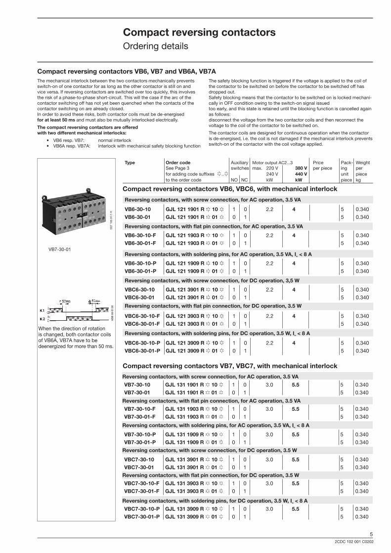
CompactreversingcontactorsVB7,VBC7,withmechanicalinterlock
CompactreversingcontactorsVB6,VB7andVB6A,VB7A
CompactreversingcontactorsVB6,VBC6,withmechanicalinterlock
When the direction of rotation is changed, both contactor coils of VB6A, VB7A have to be deenergized for more than 50 ms.
Reversingcontactors,withscrewconnection,forACoperation,3.5VA
Reversingcontactors,withscrewconnection,forACoperation,3.5VA
Reversingcontactors,withflatpinconnection,forACoperation,3.5VA
Reversingcontactors,withsolderingpins,forACoperation,3.5VA,Ith<8A
Reversingcontactors,withscrewconnection,forDCoperation,3,5W
Reversingcontactors,withflatpinconnection,forDCoperation,3.5W
Reversingcontactors,withsolderingpins,forDCoperation,3.5W,Ith<8A
Reversingcontactors,withflatpinconnection,forACoperation,3.5VA
Reversingcontactors,withsolderingpins,forACoperation,3.5VA,Ith<8A
Reversingcontactors,withscrewconnection,forDCoperation,3.5W
Reversingcontactors,withflatpinconnection,forDCoperation,3.5W
Reversingcontactors,withsolderingpins,forDCoperation,3.5W,Ith<8A
Type Ordercode Auxiliary Motor output AC2...� Price Pack- Weight See Page � switches max. 220 V 380V per piece ing per for adding code suffixes ¨..¨ 240 V 440V unit piece to the order code NO NC kW kW piece kg
The mechanical interlock between the two contactors mechanically prevents switch-on of one contactor for as long as the other contactor is still on and vice versa. If reversing contactors are switched over too quickly, this involves the risk of a phase-to-phase short-circuit. This will the case if the arc of the contactor switching off has not yet been quenched when the contacts of the contactor switching on are already closed. In order to avoid these risks, both contactor coils must be de-energised foratleast50ms and must also be mutually interlocked electrically.
Thecompactreversingcontactorsareofferedwithtwodifferentmechanicalinterlocks:
• VB6 resp. VB7: normal interlock • VB6A resp. VB7A: interlock with mechanical safety blocking function
The safety blocking function is triggered if the voltage is applied to the coil of the contactor to be switched on before the contactor to be switched off has dropped out. Safety blocking means that the contactor to be switched on is locked mechani-cally in OFF condition owing to the switch-on signal issued too early, and this state is retained until the blocking function is cancelled again as follows: disconnect the voltage from the two contactor coils and then reconnect the voltage to the coil of the contactor to be switched on.
The contactor coils are designed for continuous operation when the contactor is de-energised, i.e. the coil is not damaged if the mechanical interlock prevents switch-on of the contactor with the coil voltage applied.

62CDC 102 001 C0202
Type Ordercode Auxiliary Motor output AC2...� Price Pack- Weight See Page � switches 220 V 380V per unit ing per for adding code suffixes ¨..¨ 240 V 440V unit piece to the order code NO NC kW kW piece kg
VB6A-30-10 GJL1211911R¨ 10¨ 1 0 2.2 4 5 0.�40
VB6A-30-01 GJL1211911R¨ 01¨ 0 1 5 0.�40
VB6A-30-10-F GJL1211913R¨ 10¨ 1 0 2.2 4 5 0.�40
VB6A-30-01-F GJL1211913R¨ 01¨ 0 1 5 0.�40
VB6A-30-10-P GJL1211919R¨ 10¨ 1 0 2.2 4 5 0.�40
VB6A-30-01-P GJL1211919R¨ 01¨ 0 1 5 0.�40
VBC6A-30-10 GJL1213911R¨ 10¨ 1 0 2.2 4 5 0.�40
VBC6A-30-01 GJL1213911R¨ 01¨ 0 1 5 0.�40
VBC6A-30-10-F GJL1213913R¨ 10¨ 1 0 2.2 4 5 0.�40
VBC6A-30-01-F GJL1213913R¨ 01¨ 0 1 5 0.�40
VBC6A-30-10-PGJL1213919R¨ 10¨ 1 0 2.2 4 5 0.�40
VBC6A-30-01-PGJL1213919R¨ 01¨ 0 1 5 0.�40
VB7A-30-10 GJL1311911R¨ 10¨ 1 0 �.0 5.5 5 0.�40
VB7A-30-01 GJL1311911R¨ 01¨ 0 1 5 0.�40
VB7A-30-10-F GJL1311913R¨ 10¨ 1 0 �.0 5.5 5 0.�40
VB7A-30-01-F GJL1311913R¨ 01¨ 0 1 5 0.�40
VB7A-30-10-P GJL1311919R¨ 10¨ 1 0 �.0 5.5 5 0.�40
VB7A-30-01-P GJL1311919R¨ 01¨ 0 1 5 0.�40
VBC7A-30-10 GJL1313911R¨ 10¨ 1 0 �.0 5.5 5 0.�40
VBC7A-30-01 GJL1313911R¨ 01¨ 0 1 5 0.�40
VBC7A-30-10-F GJL1313913R¨ 10¨ 1 0 �.0 5.5 5 0.�40
VBC7A-30-01-F GJL1313913R¨ 01¨ 0 1 5 0.�40
VBC7A-30-10-P GJL1313919R¨ 10¨ 1 0 �.0 5.5 5 0.�40
VBC7A-30-01-P GJL1313919R¨ 01¨ 0 1 5 0.�40
Reversingcontactors,withscrewconnection,forACoperation,3.5VA
CompactreversingcontactorsVB7A,VBC7A,withmechanicalinterlock
Reversing contactor VBC6A-�-10 Reversing connection BMS6-�0
SS
T 27
8 92
R
CompactreversingcontactorsOrdering details
CompactreversingcontactorsVB6A,VBC6A,withmechanicalinterlockReversingcontactors,withscrewconnection,forACoperation,3.5VA
Reversingcontactors,withflatpinconnection,forACoperation,3.5VA
Reversingcontactors,withsolderingpins,forACoperation,3.5VA,Ith<8A
Reversingcontactors,withscrewconnection,forDCoperation,3.5W
Reversingcontactors,withflatpinconnection,forDCoperation,3.5W
Reversingcontactors,withsolderingpins,forDCoperation,3.5W,Ith<8A

72CDC 102 001 C0202
BC7-30-10-P-2.4 GJL1313009R5101 1 0 �.0 5.5 10 0.170BC7-30-01-P-2.4 GJL1313009R5011 0 1 �.0 5.5 10 0.170
Type Ordercode Auxiliary Motor output AC2...� Price Pack- Weight switches 220 V 380V per ing per 240 V 440V piece unit piece NO NC kW kW piece kg
BC6-30-10-1.4 GJL1213001R8101 1 0 2.2 4 10 0.180BC6-30-01-1.4 GJL1213001R8011 0 1 2.2 4 10 0.180
BC6-30-10-P-1.4 GJL1213009R8101 1 0 2.2 4 10 0.170 BC6-30-01-P-1.4 GJL1213009R8011 0 1 2.2 4 10 0.170
BC6-30-10-2.4 GJL1213001R5101 1 0 2.2 4 10 0.180BC6-30-01-2.4 GJL1213001R5011 0 1 2.2 4 10 0.180
BC6-30-10-F-2.4 GJL1213003R5101 1 0 2.2 4 10 0.170BC6-30-01-F-2.4 GJL1213003R5011 0 1 2.2 4 10 0.170
BC6-30-10-P-2.4 GJL1213009R5101 1 0 2.2 4 10 0.170BC6-30-01-P-2.4 GJL1213009R5011 0 1 2.2 4 10 0.170
BC7-30-10-P-1.4 GJL1313009R8101 1 0 �.0 5.5 10 0.170 BC7-30-01-P-1.4 GJL1313009R8011 0 1 �.0 5.5 10 0.170
BC7-30-10-F-2.4 GJL1313003R5101 1 0 �.0 5.5 10 0.170BC7-30-01-F-2.4 GJL1313003R5011 0 1 �.0 5.5 10 0.170
B6S-30-10-1.7 GJL1213001R7101 1 0 2.2 4.0 10 0.180B6S-30-01-1.7 GJL1213001R7011 0 1 2.2 4.0 10 0.180
B6S-30-10-2.8 GJL1213001R7102 1 0 2.2 4.0 10 0.180B6S-30-01-2.8 GJL1213001R7012 0 1 2.2 4.0 10 0.180
B7S-30-10-1.7 GJL1313001R7101 1 0 �.0 5.5 10 0.180B7S-30-01-1.7 GJL1313001R7011 0 1 �.0 5.5 10 0.180
B7S-30-10-2.8 GJL1313001R7102 1 0 �.0 5.5 10 0.180B7S-30-01-2.8 GJL1313001R7012 0 1 �.0 5.5 10 0.180
Motorcontactors,withscrewconnection,forDCoperation24V/1.7W
Motorcontactors,withscrewconnection,forDCoperation24V/1.7W
InterfacecontactorsBC6 Auxiliary switch blocks cannot be fitted later on !
InterfacecontactorsBC7Auxiliary switch blocks cannot be fitted later on !
– Controlled directly by PLC
– Integrated protective circuit with diodes and additional surge suppressor
– Non-confusible coil connection
– You save time and money for additional external wiring
– Thermal overload relay T7DU available as accessory, see Page 19.
AB
B 8
9 08
44/1
R
BC7-�0-10-1.4
SS
T 01
6 91
KS
ST
016
91 K
Motorcontactors,withscrewconnection,forDCoperation17...32V/2.4W
Motorcontactors,withscrewconnection,forDCoperation17...32V/2.4W
Oscillograms
Without protective circuit
With integrated protective circuit
MinicontactorsforconnectiontoPLCsB7S...withintegratedprotectivecircuitAuxiliary switch blocks cannot be fitted later on !
Motorcontactors,withsolderingpins,forDCoperation17...32V/2.4W,Ith<8A
InterfacecontactorsMinicontactorsforconnectiontoPLCsOrdering details
Motorcontactors,withscrewconnection,forDCoperation24V/1.4W
-1000 V
024 V
Ohne Beschaltung
0 280 µs
024 V
Mit interner Beschaltung
0Ausschaltung
�
Oszillogramme
-1000 V
024 V
Ohne Beschaltung
0 280 µs
024 V
Mit interner Beschaltung
0Ausschaltung
�
Oszillogramme
Motorcontactors,withscrewconnection,forDCoperation24V/1.4W
Motorcontactors,withflatpinconnection,forDCoperation24V/1.4W
Motorcontactors,withsolderingpins,forDCoperation24V/1.4W,Ith<8A
Motorcontactors,withflatpinconnection,forDCoperation17...32V/2.4W
Motorcontactors,withflatpinconnection,forDCoperation24V/1.4W
Motorcontactors,withsolderingpins,forDCoperation24V/1.4W,Ith<8A
Motorcontactors,withflatpinconnection,forDCoperation17...32V/2.4W
Motorcontactors,withsolderingpins,forDCoperation17...32V/2.4W,Ith<8A
Motorcontactors,withscrewconnection,forDCoperation17...32V/2.8W
Motorcontactors,withscrewconnection,forDCoperation17...32V/2.8W
BC6-30-10-F-1.4 GJL1213003R8101 1 0 2.2 4 10 0.180BC6-30-01-F-1.4 GJL1213003R8011 0 1 2.2 4 10 0.180
BC7-30-10-1.4 GJL1313001R8101 1 0 �.0 5.5 10 0.170 BC7-30-01-1.4 GJL1313001R8011 0 1 �.0 5.5 10 0.170
BC7-30-10-F-1.4 GJL1313003R8101 1 0 �.0 5.5 10 0.170 BC7-30-01-F-1.4 GJL1313003R8011 0 1 �.0 5.5 10 0.170
BC7-30-10-2.4 GJL1313001R5101 1 0 �.0 5.5 10 0.170 BC7-30-01-2.4 GJL1313001R5011 0 1 �.0 5.5 10 0.170
MinicontactorsforconnectiontoPLCsB6S...withintegratedprotectivecircuitAuxiliary switch blocks cannot be fitted later on !
82CDC 102 001 C0202
Type Ordercode Auxiliary AC15 Price Pack- Weight See Page � switches 220 V �80 V 500 V per ing per for adding code suffixes ¨..¨ 240 V 440 V piece unit piece to the order code NO NC A A A piece kg
K6-40E GJH1211001R¨ 40¨ 4 0 4 � 2 10 0.180K6-31Z GJH1211001R¨ 31¨ � 1 4 � 2 10 0.180K6-22Z GJH1211001R¨ 22¨ 2 2 4 � 2 10 0.180
K6-40E-F GJH1211003R¨ 40¨ 4 0 4 � 2 10 0.170K6-31Z-F GJH1211003R¨ 31¨ � 1 4 � 2 10 0.170K6-22Z-F GJH1211003R¨ 22¨ 2 2 4 � 2 10 0.170
K6-40E-P GJH1211009R¨ 40¨ 4 0 4 � 2 10 0.170K6-31Z-P GJH1211009R¨ 31¨ � 1 4 � 2 10 0.170K6-22Z-P GJH1211009R¨ 22¨ 2 2 4 � 2 10 0.170
KC6-40E GJH1213001R¨ 40¨ 4 0 4 � 2 10 0.180KC6-31Z GJH1213001R¨ 31¨ � 1 4 � 2 10 0.180KC6-22Z GJH1213001R¨ 22¨ 2 2 4 � 2 10 0.180
KC6-40E-F GJH1213003R¨ 40¨ 4 0 4 � 2 10 0.170KC6-31Z-F GJH1213003R¨ 31¨ � 1 4 � 2 10 0.170KC6-22Z-F GJH1213003R¨ 22¨ 2 2 4 � 2 10 0.170
KC6-40E-P GJH1213009R¨ 40¨ 4 0 4 � 2 10 0.170KC6-31Z-P GJH1213009R¨ 31¨ � 1 4 � 2 10 0.170KC6-22Z-P GJH1213009R¨ 22¨ 2 2 4 � 2 10 0.170
KC6-40E-1.4 GJH1213001R8401 4 0 4 � 2 10 0.180KC6-31Z-1.4 GJH1213001R8311 � 1 4 � 2 10 0.180
KC6-40E-P-1.4 GJH1213009R8401 4 0 4 � 2 10 0.170KC6-31Z-P-1.4 GJH1213009R8311 � 1 4 � 2 10 0.170
KC6-40E-2.4 GJH1213001R5401 4 0 4 � 2 10 0.180KC6-31Z-2.4 GJH1213001R5311 � 1 4 � 2 10 0.180
KC6-40E-F-2.4 GJH1213003R5401 4 0 4 � 2 10 0.170KC6-31Z-F-2.4 GJH1213003R5311 � 1 4 � 2 10 0.170
KC6-40E-P-2.4 GJH1213009R5401 4 0 4 � 2 10 0.170KC6-31Z-P-2.4 GJH1213009R5311 � 1 4 � 2 10 0.170
K6S-40E-1.7 GJH1213001R7401 4 0 4 � 2 10 0.180K6S-31Z-1.7 GJH1213001R7311 � 1 4 � 2 10 0.180K6S-22Z-1.7 GJH1213001R7221 2 2 4 � 2 10 0.180
K6S-40E-2.8 GJH1213001R7402 4 0 4 � 2 10 0.180K6S-31Z-2.8 GJH1213001R7312 � 1 4 � 2 10 0.180K6S-22Z-2.8 GJH1213001R7222 2 2 4 � 2 10 0.180
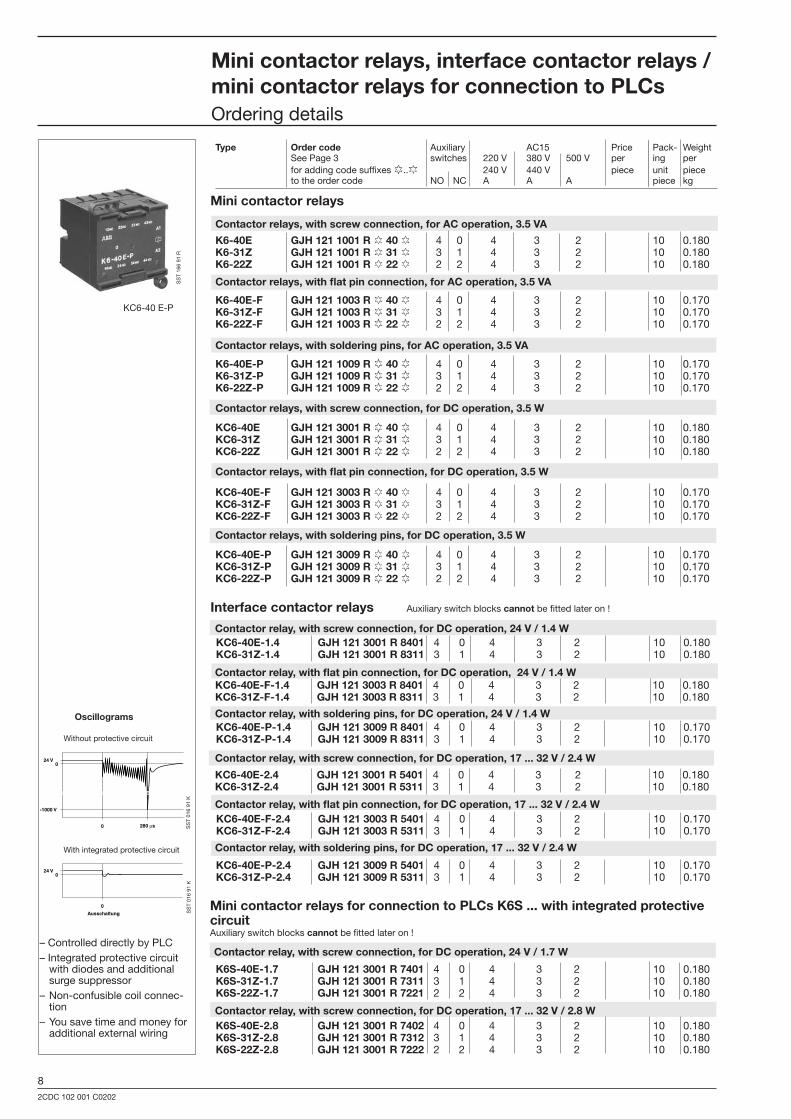
Minicontactorrelays,interfacecontactorrelays/minicontactorrelaysforconnectiontoPLCsOrdering details
KC6-40 E-P
SS
T 16
6 91
R
Minicontactorrelays
– Controlled directly by PLC– Integrated protective circuit with diodes and additional surge suppressor– Non-confusible coil connec- tion– You save time and money for additional external wiring
SS
T 01
6 91
KS
ST
016
91 K
Oscillograms
Without protective circuit
With integrated protective circuit
Interfacecontactorrelays Auxiliary switch blocks cannotbe fitted later on !
MinicontactorrelaysforconnectiontoPLCsK6S...withintegratedprotectivecircuit Auxiliary switch blocks cannotbe fitted later on !
Contactorrelay,withscrewconnection,forDCoperation,24V/1.7W
Contactorrelay,withscrewconnection,forDCoperation,24V/1.4W
Contactorrelays,withscrewconnection,forACoperation,3.5VA
Contactorrelays,withflatpinconnection,forACoperation,3.5VA
Contactorrelays,withsolderingpins,forACoperation,3.5VA
Contactorrelays,withscrewconnection,forDCoperation,3.5W
Contactorrelays,withflatpinconnection,forDCoperation,3.5W
Contactorrelays,withsolderingpins,forDCoperation,3.5W
Contactorrelay,withflatpinconnection,forDCoperation,24V/1.4W
Contactorrelay,withsolderingpins,forDCoperation,24V/1.4W
Contactorrelay,withscrewconnection,forDCoperation,17...32V/2.4W
Contactorrelay,withflatpinconnection,forDCoperation,17...32V/2.4W
Contactorrelay,withsolderingpins,forDCoperation,17...32V/2.4W
Contactorrelay,withscrewconnection,forDCoperation,17...32V/2.8W
KC6-40E-F-1.4 GJH1213003R8401 4 0 4 � 2 10 0.180KC6-31Z-F-1.4 GJH1213003R8311 � 1 4 � 2 10 0.180
-1000 V
024 V
Ohne Beschaltung
0 280 µs
024 V
Mit interner Beschaltung
0Ausschaltung
�
Oszillogramme
-1000 V
024 V
Ohne Beschaltung
0 280 µs
024 V
Mit interner Beschaltung
0Ausschaltung
�
Oszillogramme
92CDC 102 001 C0202
K6-40E GJH1211001R¨ 40¨ 4 0 4 � 2 10 0.180K6-31Z GJH1211001R¨ 31¨ � 1 4 � 2 10 0.180K6-22Z GJH1211001R¨ 22¨ 2 2 4 � 2 10 0.180
TBC7-30-10 GJL1313061R10 1 0 20 � 5,5 4 10 0.180TBC7-30-01 GJL1313061R01 0 1 20 � 5.5 4 10 0.180
TKC6-22Z GJH1213061R¨ 22¨ 2 2 6 10 0.180TKC6-31Z GJH1213061R¨ 31¨ 2 2 6 10 0.180TKC6-40E GJH1213061R¨ 40¨ 4 0 6 10 0.180
TKC6-22Z-F GJH1213063R¨ 22¨ 2 2 6 10 0.180TKC6-31Z-F GJH1213063R¨ 31¨ 2 2 6 10 0.180TKC6-40E-F GJH1213063R¨ 40¨ 4 0 6 10 0.180
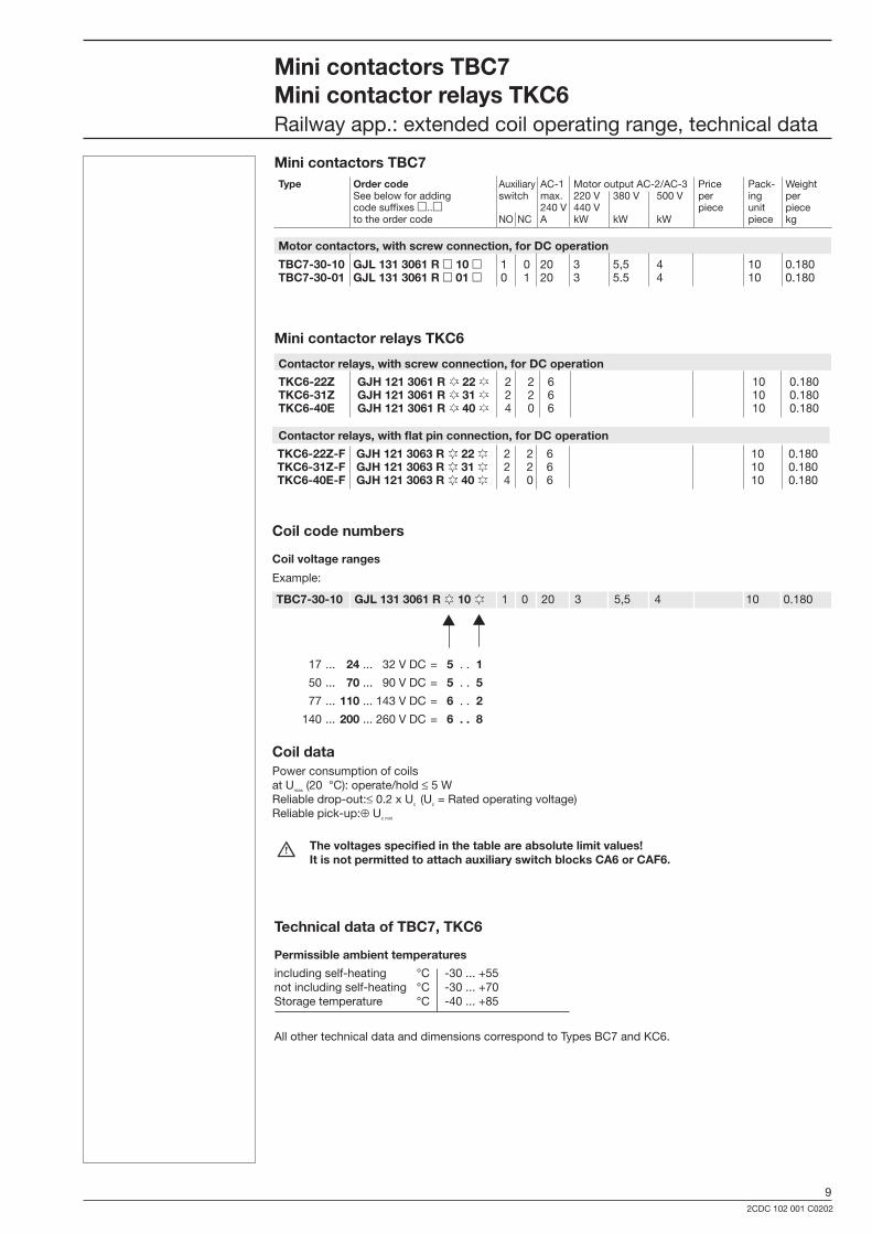
Contactorrelays,withscrewconnection,forDCoperation
MinicontactorsTBC7
MinicontactorsTBC7MinicontactorrelaysTKC6Railway app.: extended coil operating range, technical data
MinicontactorrelaysTKC6
Motorcontactors,withscrewconnection,forDCoperation
17 ... 24... �2 V DC = 5. . 1
50 ... 70... 90 V DC = 5 . . 5
77 ... 110... 14� V DC = 6 . . 2
140 ... 200... 260 V DC = 6..8
CoildataPower consumption of coilsat Umax (20 °C): operate/hold ≤ 5 WReliable drop-out:≤ 0.2 x Uc (Uc = Rated operating voltage)Reliable pick-up:⊕ Uc min
Thevoltagesspecifiedinthetableareabsolutelimitvalues! ItisnotpermittedtoattachauxiliaryswitchblocksCA6orCAF6.
TechnicaldataofTBC7,TKC6
Permissibleambienttemperatures
including self-heating °C -�0 ... +55 not including self-heating °C -�0 ... +70 Storage temperature °C -40 ... +85
All other technical data and dimensions correspond to Types BC7 and KC6.
Contactorrelays,withflatpinconnection,forDCoperation
Type Ordercode Auxiliary AC-1 Motor output AC-2/AC-� Price Pack- Weight See below for adding switch max. 220 V �80 V 500 V per ing per code suffixes .. 240 V 440 V piece unit piece to the order code NO NC A kW kW kW piece kg
Coilcodenumbers
Coilvoltageranges
Example:
TBC7-30-10 GJL1313061R¨ 10¨ 1 0 20 � 5,5 4 10 0.180
102CDC 102 001 C0202
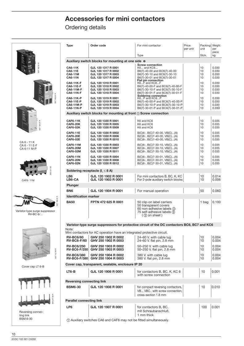
AuxiliaryswitchblocksformountingatfrontScrewconnection
Type Ordercode For mini contactor Price Packing Weight per unit unit per piece Type Stck. kg
CA6-11K GJL1201317R0001 K6... and KC6... 10 0.0�0CA6-11E GJL1201317R0002 B6(7)-40-00 and BC6(7)-40-00 10 0.0�0CA6-11M GJL1201317R0003 B6(7)-�0-10 and BC6(7)-�0-10 10 0.0�0CA6-11N GJL1201317R0004 B6(7)-�0-01 and BC6(7)-�0-01 10 0.0�0
CA6-11K-F GJL1201318R0001 K6...F and KC6...F 10 0.0�0CA6-11E-F GJL1201318R0002 B6(7)-40-00-F and BC6(7)-40-00-F 10 0.0�0CA6-11M-F GJL1201318R0003 B6(7)-�0-10-F and BC6(7)-�0-10-F 10 0.0�0CA6-11N-F GJL1201318R0004 B6(7)-�0-01-F and BC6(7)-�0-01-F 10 0.0�0
CA6-11K-P GJL1201319R0001 K6...P and KC6...P 10 0.0�0CA6-11E-P GJL1201319R0002 B6(7)-40-00-P and BC6(7)-40-00-P 10 0.0�0CA6-11M-P GJL1201319R0003 B6(7)-�0-10-P and BC6(7)-�0-10-P 10 0.0�0CA6-11N-P GJL1201319R0004 B6(7)-�0-01-P and BC6(7)-�0-01-P 10 0.0�0
CAF6-11K GJL1201330R0001 K6 and KC6 10 0.0�5CAF6-20K GJL1201330R0005 K6 and KC6 10 0.0�5CAF6-02K GJL1201330R0009 K6 and KC6 10 0.0�5
CAF6-11E GJL1201330R0002 B(C)6-, B(C)7-40-00, VB(C)...(A) 10 0.0�5CAF6-20E GJL1201330R0006 B(C)6-, B(C)7-40-00, VB(C)...(A) 10 0.0�5CAF6-02E GJL1201330R0010 B(C)6-, B(C)7-40-00, VB(C)...(A) 10 0.0�5
CAF6-11M GJL1201330R0003 B(C)6-, B(C)7-�0-10, VB(C)...(A) 10 0.0�5CAF6-20M GJL1201330R0007 B(C)6-, B(C)7-�0-10, VB(C)...(A) 10 0.0�5CAF6-02M GJL1201330R0011 B(C)6-, B(C)7-�0-10, VB(C)...(A) 10 0.0�5
CAF6-11N GJL1201330R0004 B(C)6-, B(C)7-�0-01, VB(C)...(A) 10 0.0�5CAF6-20N GJL1201330R0008 B(C)6-, B(C)7-�0-01, VB(C)...(A) 10 0.0�5CAF6-02N GJL1201330R0012 B(C)6-, B(C)7-�0-01, VB(C)...(A) 10 0.0�5
LB6 GJL1201902R0001 For mini contactors B, BC, K, KC 10 0.014LB6-CA GJL1201903R0001 For 2-pole auxiliary switch blocks 10 0.006
BN6 GJL1201904R0001 For manual operation 50 0.060
BA50 FPTN472625R0001 50 clip-on label carriers 1 bag 0.100 50 transparent covers 60 non-adhesive labels 75 self-adhesive labels ( on sheet )
RV-BC6/60 GHV2501902R0002 24–60 V. with cable lug 10 0.004RV-BC6-F/60 GHV2501902R0003 24–60 V. flat pin, 2.8 mm 10 0.004
RV-BC6/250 GHV2501903R0002 50–250 V. with cable lug 10 0.004RV-BC6-F/250 GHV2501903R0003 50–250 V. flat pin, 2.8 mm 10 0.004
RV-BC6/380 GHV2501904R0002 �80 V. with cable lug 10 0.004RV-BC6-F/380 GHV2501904R0003 �80 V. flat pin, 2.8 mm 10 0.004
BSM6-30 GJL1201908R0001 for compact reversing contactors, 10 0.010 VB.., VBC.. with screw connection, cross-section 1.8 mm2
LP6 GJL1201907R0001 for contactors B, BC, 100 0.001 mit Schraubanschluß, 1 mm thick
CA 6 - 11 KCA 6 - 11 E-FCA 6-11 M-P
SS
T 16
4 91
R
SS
T 16
� 91
R
SS
T 16
2 91
R
Reversing connec-ting linkBSM 6-�0
SS
T 27
7 92
R
Cover cap LT 6-B
SS
T 14
7 90
R
Varistor-type surge suppressor RV-BC 6/...
SS
T 18
6 91
R
SS
T 01
1 9�
CAF6- 11M
AccessoriesforminicontactorsOrdering details
Covercap,transparent,sealable,enclosureIP20
Flatpinconnection
Screwconnection
Solderingconnection
Auxiliaryswitchblocksformountingatoneside➋
Solderingreceptacle(Ith≤8A)
Plunger
Identificationmarker
Varistor-typesurgesuppressorsforprotectivecircuitoftheDCcontactorsBC6,BC7andKC6
Note: Mini contactors for AC operation have an integrated protective circuit.
Reversingconnectinglink
Parallelconnectinglink
Auxiliary switches CA6 and CAF6 may not be fitted simultaneously.
LT6-B GJL1201906R0001 for contactors B, BC, K, KC 6 10 0.001 with screw connection
112CDC 102 001 C0202
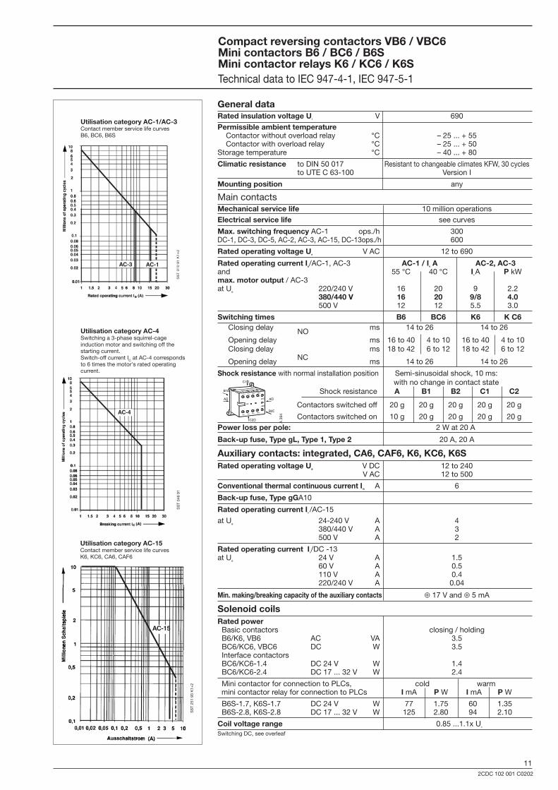
General dataRated insulation voltage Ui V 690
Permissible ambient temperature Contactor without overload relay °C – 25 ... + 55 Contactor with overload relay °C – 25 ... + 50Storage temperature °C – 40 ... + 80
Climatic resistance to DIN 50 017 Resistant to changeable climates KFW, 30 cycles to UTE C 63-100 Version I
Mounting position any
Main contactsMechanical service life 10 million operations
Electrical service life see curves
Max. switching frequency AC-1 ops./h 300DC-1, DC-3, DC-5, AC-2, AC-3, AC-15, DC-13 ops./h 600
Rated operating voltage Ue V AC 12 to 690
Rated operating current Ie/AC-1, AC-3 AC-1 / Ie A AC-2, AC-3and 55 °C 40 °C Ie A P kWmax. motor output / AC-3at Ue 220/240 V 16 20 9 2.2 380/440 V 16 20 9/8 4.0 500 V 12 12 5.5 3.0
Switching times B6 BC6 K6 K C6 Closing delay ms 14 to 26 14 to 26 NO Opening delay ms 16 to 40 4 to 10 16 to 40 4 to 10 Closing delay ms 18 to 42 6 to 12 18 to 42 6 to 12 NC Opening delay ms 14 to 26 14 to 26
Shock resistance with normal installation position Semi-sinusoidal shock, 10 ms: with no change in contact state Shock resistance A B1 B2 C1 C2
Contactors switched off 20 g 20 g 20 g 20 g 20 g
Contactors switched on 10 g 20 g 20 g 20 g 20 gPower loss per pole: 2 W at 20 A
Back-up fuse, Type gL, Type 1, Type 2 20 A, 20 A
Auxiliary contacts: integrated, CA6, CAF6, K6, KC6, K6SRated operating voltage Ue V DC 12 to 240 V AC 12 to 500
Conventional thermal continuous current Ith A 6
Back-up fuse, Type gGA10
Rated operating current Ie /AC-15
at Ue 24-240 V A 4 380/440 V A 3 500 V A 2
Rated operating current Ie/DC -13at Ue 24 V A 1.5 60 V A 0.5 110 V A 0.4 220/240 V A 0.04
Min. making/breaking capacity of the auxiliary contacts ⊕ 17 V and ⊕ 5 mA
Solenoid coilsRated power Basic contactors closing / holding B6/K6, VB6 AC VA 3.5 BC6/KC6, VBC6 DC W 3.5 Interface contactors BC6/KC6-1.4 DC 24 V W 1.4 BC6/KC6-2.4 DC 17 ... 32 V W 2.4
Mini contactor for connection to PLCs, cold warm mini contactor relay for connection to PLCs I mA P W I mA P W
B6S-1.7, K6S-1.7 DC 24 V W 77 1.75 60 1.35 B6S-2.8, K6S-2.8 DC 17 ... 32 V W 125 2.80 94 2.10
Coil voltage range 0.85 ...1.1x Uc
Switching DC, see overleaf
SS
T 04
6 91
SS
T 01
0 91
K1+
2
AC-4
SS
T 25
1 93
K1+
2
AC-15
Utilisation category AC-15 Contact member service life curvesK6, KC6, CA6, CAF6
Compact reversing contactors VB6 / VBC6Mini contactors B6 / BC6 / B6S Mini contactor relays K6 / KC6 / K6STechnical data to IEC 947-4-1, IEC 947-5-1
A1�
14NO�6T3�4T2�2T1�
1L1� 3L2� 5L3� 13NO�
0�A2�
B2�
A�
C1�
B1�
A�
C2�
A 3
94
AC-3 AC-1
Utilisation category AC-1/AC-3Contact member service life curvesB6, BC6, B6S
Utilisation category AC-4Switching a 3-phase squirrel-cage induction motor and switching off the starting current.Switch-off current IC at AC-4 corresponds to 6 times the motor's rated operating current.
122CDC 102 001 C0202
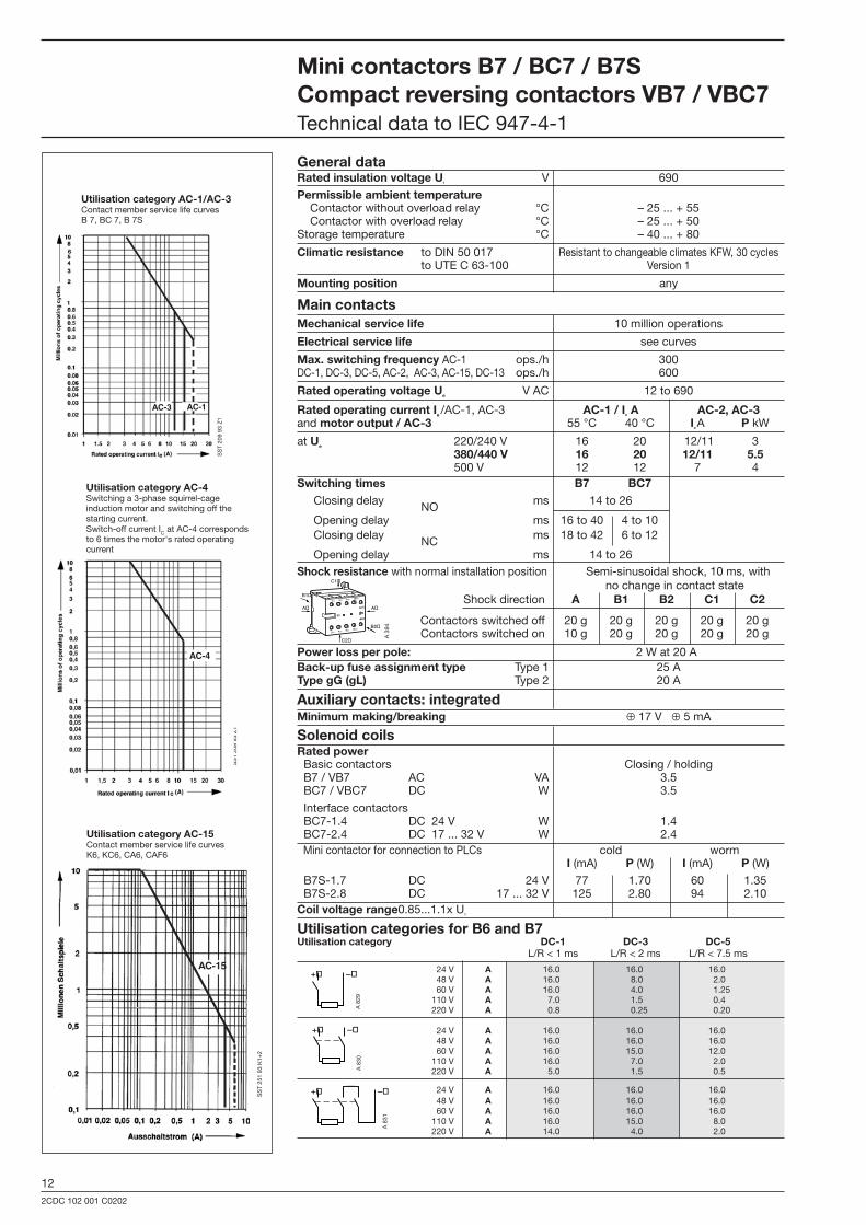
General dataRated insulation voltage Ui V 690
Permissible ambient temperature Contactor without overload relay °C – 25 ... + 55 Contactor with overload relay °C – 25 ... + 50Storage temperature °C – 40 ... + 80
Climatic resistance to DIN 50 017 Resistant to changeable climates KFW, 30 cycles to UTE C 63-100 Version 1
Mounting position any
Main contactsMechanical service life 10 million operations
Electrical service life see curves
Max. switching frequency AC-1 ops./h 300DC-1, DC-3, DC-5, AC-2, AC-3, AC-15, DC-13 ops./h 600
Rated operating voltage Ue V AC 12 to 690
Rated operating current Ie /AC-1, AC-3 AC-1 / Ie A AC-2, AC-3and motor output / AC-3 55 °C 40 °C Ie A P kW
at Ue 220/240 V 16 20 12/11 3 380/440 V 16 20 12/11 5.5 500 V 12 12 7 4Switching times B7 BC7 Closing delay ms 14 to 26 NO Opening delay ms 16 to 40 4 to 10 Closing delay ms 18 to 42 6 to 12 NC Opening delay ms 14 to 26Shock resistance with normal installation position Semi-sinusoidal shock, 10 ms, with no change in contact state Shock direction A B1 B2 C1 C2
Contactors switched off 20 g 20 g 20 g 20 g 20 g Contactors switched on 10 g 20 g 20 g 20 g 20 g
Power loss per pole: 2 W at 20 ABack-up fuse assignment type Type 1 25 AType gG (gL) Type 2 20 A
Auxiliary contacts: integratedMinimum making/breaking ⊕ 17 V ⊕ 5 mA
Solenoid coilsRated power Basic contactors Closing / holding B7 / VB7 AC VA 3.5 BC7 / VBC7 DC W 3.5
Interface contactors BC7-1.4 DC 24 V W 1.4 BC7-2.4 DC 17 ... 32 V W 2.4 Mini contactor for connection to PLCs cold worm I (mA) P (W) I (mA) P (W)
B7S-1.7 DC 24 V 77 1.70 60 1.35 B7S-2.8 DC 17 ... 32 V 125 2.80 94 2.10Coil voltage range0.85...1.1x Uc
Utilisation categories for B6 and B7 Utilisation category DC-1 DC-3 DC-5 L/R < 1 ms L/R < 2 ms L/R < 7.5 ms
24 V A 16.0 16.0 16.0 48 V A 16.0 8.0 2.0 60 V A 16.0 4.0 1.25 110 V A 7.0 1.5 0.4 220 V A 0.8 0.25 0.20
24 V A 16.0 16.0 16.0 48 V A 16.0 16.0 16.0 60 V A 16.0 15.0 12.0 110 V A 16.0 7.0 2.0 220 V A 5.0 1.5 0.5
24 V A 16.0 16.0 16.0 48 V A 16.0 16.0 16.0 60 V A 16.0 16.0 16.0 110 V A 16.0 15.0 8.0 220 V A 14.0 4.0 2.0
Mini contactors B7 / BC7 / B7S Compact reversing contactors VB7 / VBC7 Technical data to IEC 947-4-1
–�+�
A 8
29A
830
–�+�
–�+�
SST 209 93K
SST 209 93
AC-3 AC-1
101 30201,5 2 3 4 5 6 8
Nennstrom
15
Mill
ione
n Sc
halts
piel
e
0,02
0,030,040,050,060,08
0,2
0,30,40,50,60,8
34568
10
2
1
0,1
0,01
SS
T 20
9 93
Z1
SS
T 20
8 93
Z1
A1�
14NO�6T3�4T2�2T1�
1L1� 3L2� 5L3� 13NO�
0�A2�
B2�
A�
C1�
B1�
A�
C2�
A 3
94
Utilisation category AC-1/AC-3Contact member service life curvesB 7, BC 7, B 7S
Utilisation category AC-4Switching a 3-phase squirrel-cage induction motor and switching off the starting current.Switch-off current IC at AC-4 corresponds to 6 times the motor's rated operating current
SST 208 93 K
AC-4
SS
T 25
1 93
K1+
2
AC-15
Utilisation category AC-15Contact member service life curvesK6, KC6, CA6, CAF6
A 8
31

132CDC 102 001 C0202
Contact member service life for utilisation categories DC-1, DC-3, DC-5
The following curves show the contact member service life for utilisa-tion categories DC-1, DC-3 and DC-5 for 3 poles in series. If only one current path is used, the service life read off for the related breaking capacity must be multiplied by 0.33, and, if there are 2 current paths, it must be multiplied by 0.66.
The time constants L/R (ms) which differ for the individual utilisation categories have been allowed for on the curves.
A = 3 poles in series DC-1B = 3 poles in series DC-3C = 3 poles in series DC-5
Mini contactors B6, B7 / BC6, BC7Compact reversing contactors VB6(7) / VBC6(7)Contact member service life, utilisation categories
89 6
151/
1 +
2
142CDC 102 001 C0202
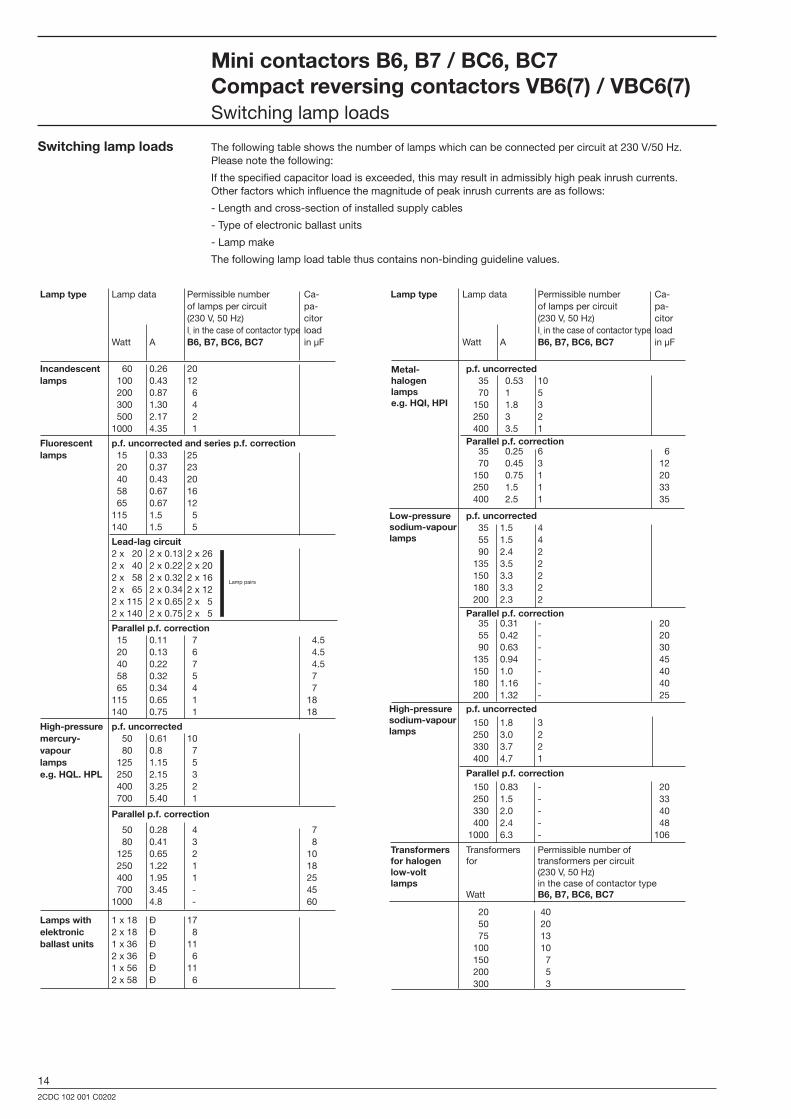
Lamp type Lamp data Permissible number Ca- of lamps per circuit pa- (230 V, 50 Hz) citor In in the case of contactor type load Watt A B6, B7, BC6, BC7 in µF
p.f. uncorrected 35 0.53 10 70 1 5 150 1.8 3 250 3 2 400 3.5 1 Parallel p.f. correction 35 0.25 6 6 70 0.45 3 12 150 0.75 1 20 250 1.5 1 33 400 2.5 1 35
p.f. uncorrected 35 1.5 4 55 1.5 4 90 2.4 2 135 3.5 2 150 3.3 2 180 3.3 2 200 2.3 2
Parallel p.f. correction 35 0.31 - 20 55 0.42 - 20 90 0.63 - 30 135 0.94 - 45 150 1.0 - 40 180 1.16 - 40 200 1.32 - 25
p.f. uncorrected 150 1.8 3 250 3.0 2 330 3.7 2 400 4.7 1
Parallel p.f. correction 150 0.83 - 20 250 1.5 - 33 330 2.0 - 40 400 2.4 - 48 1000 6.3 - 106
Transformers Transformers Permissible number of for halogen for transformers per circuitlow-volt (230 V, 50 Hz)lamps in the case of contactor type Watt B6, B7, BC6, BC7
20 40 50 20 75 13 100 10 150 7 200 5 300 3
High-pressuresodium-vapourlamps
Low-pressure sodium-vapour lamps
Metal- halogenlamps e.g. HQI, HPI
Mini contactors B6, B7 / BC6, BC7Compact reversing contactors VB6(7) / VBC6(7)Switching lamp loads
Lamp type Lamp data Permissible number Ca- of lamps per circuit pa- (230 V, 50 Hz) citor In in the case of contactor type load Watt A B6, B7, BC6, BC7 in µF
Incandescent 60 0.26 20lamps 100 0.43 12 200 0.87 6 300 1.30 4 500 2.17 2 1000 4.35 1
Fluorescent p.f. uncorrected and series p.f. correctionlamps 15 0.33 25 20 0.37 23 40 0.43 20 58 0.67 16 65 0.67 12 115 1.5 5 140 1.5 5
Lead-lag circuit 2 x 20 2 x 0.13 2 x 26 2 x 40 2 x 0.22 2 x 20 2 x 58 2 x 0.32 2 x 16 Lamp pairs
2 x 65 2 x 0.34 2 x 12 2 x 115 2 x 0.65 2 x 5 2 x 140 2 x 0.75 2 x 5
Parallel p.f. correction 15 0.11 7 4.5 20 0.13 6 4.5 40 0.22 7 4.5 58 0.32 5 7 65 0.34 4 7 115 0.65 1 18 140 0.75 1 18
High-pressure p.f. uncorrectedmercury- 50 0.61 10vapour 80 0.8 7lamps 125 1.15 5 e.g. HQL. HPL 250 2.15 3 400 3.25 2 700 5.40 1
Parallel p.f. correction
50 0.28 4 7 80 0.41 3 8 125 0.65 2 10 250 1.22 1 18 400 1.95 1 25 700 3.45 - 45 1000 4.8 - 60
Lamps with 1 x 18 Ð 17elektronic 2 x 18 Ð 8ballast units 1 x 36 Ð 11 2 x 36 Ð 6 1 x 56 Ð 11 2 x 58 Ð 6
Switching lamp loads The following table shows the number of lamps which can be connected per circuit at 230 V/50 Hz. Please note the following:
If the specified capacitor load is exceeded, this may result in admissibly high peak inrush currents. Other factors which influence the magnitude of peak inrush currents are as follows:
- Length and cross-section of installed supply cables
- Type of electronic ballast units
- Lamp make
The following lamp load table thus contains non-binding guideline values.

152CDC 102 001 C0202
EL Abbreviation SEV DEMKO NEMKO SEMKO Inspect. CS Validity Switzerland Denmark Norway Sweden Finland Canada USA
GLGermany
Motor rating for contactors B(C)7 :Rated operating voltage Ue ~ (V) 110/120 V 220/240 V 440/480 V 540/600 V Motor output P (hp) 1 3 5 53-phase Ie (A) 8.4 9.6 7.6 6.1
Motor output P (hp) 1 2 2 2Single-phase Ie (A) 16 12 6 4,8
B6 30-10
91 A
043
KC6-31 Z
91 A
050
Motor rating for contactors B(C)6:Rated operating voltage Ue ~ (V) 110/120 V 220/240 V 440/480 V 540/600 V Motor output P (hp) 1 2 3 13-phase Ie (A) 8.4 6.8 1.8 1.7
Motor output P (hp) 1 2 - -Single-phase Ie (A) 16 12 - -
Amp-rating: - 12 A-300 V, AC for the main contacts of contactors B(C)6 Amp-rating: - 12 A-600 V, AC for the main contacts of contactors B(C)7
- 5 A-600 V, AC pilot duty A 600 for incorporated auxiliary contacts B(C)6, K(C)6 and B(C)7, in addition to attachable auxiliary switch blocks CA6. Values for 220 ... 208 V = (220 ... 240 V) x 1.15
Motor rating and rated operating currents in accordance with CSA and UL for contactors (B(C)6 and B(C)7, in addition to contactor relays K(C)6.
In the case of CSA and UL, the contactors are approved both for "Motor rating 3-phase" and for "AMP rating". For this reason, the permissible ratings for contactors are approved either for "hp" or "Amp rating", with an assigned rated current
respectively. The approved values for the individual contactors and contactor relays are given in the table below. The determining factor is the data indicated on the units as shown on the following table
The following equipment has been approved or approval has been requested in those countries and clas-sification societies where approval is mandatory. For some countries, special versions of equipment are available. When a supplier of a control unit incorporates approved equipment, this does not exempt him from his obligation to implement the overall installation in accordance with the legal local requirements of the country involved.
ApprovalsTest marks
Mini contactors
B6../B7.. ■ ■ ■ ■ ■ ■ ■ ■
B6/B7..-F ■ ■ ■ ■ ■ ■ ■ ■ ■
B6/B7..-P ■ ■ ■ ■ ■ ■ ■ ■ ■
BC6/BC 7.. ■ ■ ■ ■ ■ ■ ■ ■
BC6/BC 7..-F ■ ■ ■ ■ ■ ■ ■ ■ ■
BC6/BC7..-P ■ ■ ■ ■ ■ ■ ■ ■ ■
BC6/BC7..-1.4 ■ ■ ■ ■ ■ ■ ■ ■
BC6/BC7..-F-1.4 ■ ■ ■ ■ ■ ■ ■ ■
BC6/BC7..-P-1.4 ■ ■ ■ ■ ■ ■ ■
BC6/BC7..-2.4 ■ ■ ■ ■ ■ ■ ■ ■
BC6/BC7..-F-2.4 ■ ■ ■ ■ ■ ■ ■ ■
BC6/BC7..-P-2.4 ■ ■ ■ ■ ■ ■ ■ ■
B6S/B7 S ■ ■ ■
Compact reversing contactors
VB6/VB7.. ■ ■ ■ ■ ■ ■ ■ ■ ■
VBC 6/VBC7 ■ ■
Thermal overload relay
T6DU ■ ■ ■ ■ ■ ■ ■
Mini contactor relaysK6.. ■ ■ ■ ■ ■ ■ ■
K6..-F ■ ■ ■ ■ ■ ■
K6..-P ■ ■ ■ ■ ■ ■
KC6.. ■ ■ ■ ■ ■ ■ ■
KC6..-F ■ ■ ■ ■ ■ ■
KC6..-P ■ ■ ■ ■ ■ ■
KC6..-1.4 ■ ■ ■ ■ ■ ■ ■ ■
KC6..-F-1.4 ■ ■ ■ ■ ■
KC6..-P-1.4 ■ ■ ■ ■ ■ ■
KC6..-2.4 ■ ■ ■ ■ ■ ■ ■
KC6..-F-2.4 ■ ■ ■ ■ ■ ■
KC6..-P-2.4 ■ ■ ■ ■ ■ ■
AccessoriesCA6-11.. ■ ■ ■ ■ ■ ■ ■ ■
CAF6-.. ■
LB6 ■ ■ ■
LB6-CA■Normal version approved; rating plates bear the test mark if mandatory.■Submitted for approval
Mini contactors, mini contactor relaysThermal overload relay Accessories, Approvals

162CDC 102 001 C0202
13 23 33 43 A1�
14 24 34 44 A2�
13 33 43 21 A1�
14 34 44 22 A2�
13 43 21 31 A1�
14 44 22 32 A2�
A1 13 1 3 5�
A2 14 2 4 6�
1 3 5 13 A1�
2 4 6 14 A2�
1 3 5 21 A1�
2 4 6 22 A2�
A1 21 1 3 5�
A2 22 2 4 6�
1 3 5 7 A1�
2 4 6 8 A2�
1 3 5 13 A1�
2 4 6 14 A2�
1 3 5 21 A1�
2 4 6 22 A2�
MinicontactorsandminicontactorrelaysTerminal designation and location of the connection terminals
Locationoftheconnectionterminalsandterminaldesignation
Minicontactors B6(7)-40-00 ... B6(7)-�0-10 ... B6(7)-�0-01 ... BC6(7)-40-00 ... BC6(7)-�0-10 ... BC6(7)-�0-01 ...
Compactreversingcontactors VB6(7)-�0-10 ... VB6(7)-�0-01 ... VBC6(7)-�0-10 ... VBC6(7)-�0-01 ...
Minicontactorrelays K6-40 E ... K6-�1 Z ... K6-22 Z ... KC6-40 E ... KC6-�1 Z ... KC6-22 Z ...
AuxiliaryswitchesCA6/CAF6a For extending the mini contactors B6, B7, BC6, BC7, K6 and KC6 with auxiliary contactsExcept: Contactors with coils < �.5 W
AuxiliaryswitchesCA6..,attachableatside AuxiliaryswitchesCAF6, (also in the case of reversing contactors) canbescrewedonatthefront Cannot be attached on compact reversing contactors VB6(7), VBC6(7), VB6A(7) or VBC6A(7).
Connectiontype: Screw connection Connectiontype: Screw connection Flat pin connection Soldering connection Schütztypen
91 A
364
91 A
366
91 A
365
91 A
368
91 A
369
91 A
370
91 A
371
1 = CAF6- 11E 2 = CAF6- 20E 3 = CAF6- 02E
1 = CAF6- 11M 2 = CAF6- 20M 3 = CAF6- 02M
1 = CAF6- 11N 2 = CAF6- 20N 3 = CAF6- 02N 1 = CAF6- 11K 2 = CAF6- 20K 3 = CAF6- 02K
1 2 3
SST
239...
250
93 S
CA6-11E B(C)6(7)-40-00 B(C)6(7)-40-00 CA6-11E-F B(C)6(7)-40-00-F CA6-11E-P B(C)6(7)-40-00-P
CA6-11M B(C)6(7)-�0-10 B(C)6(7)-�0-10 CA6-11M-F B(C)6(7)-�0-10-F CA6-11M-P B(C)6(7)-�0-10-P
CA6-11N B(C)6(7)-�0-01 B(C)6(7)-�0-01 CA6-11N-F B(C)6(7)-�0-01-F CA6-11N-P B(C)6(7)-�0-01-P
CA6-11K K(C)6 ..... K(C)6 ..... CA6-11K-F K(C)6 ..... F CA6-11K-P K(C)6 ..... P
Only one CA 6 or one CAF 6 auxiliary switch can be attached to a contactor in each case
1 3 5 7�
2 4 6 8�
13 21�
14 22�➟�
1 3 5 13�
2 4 6 14�
33 21�
34 22�➟�
1 3 5 21�
2 4 6 22�
13 31�
14 32�➟�
53 61�
54 62�➟�
40 E��31 Z��22 Z�
91 A
371
91 A
370
91 A
369
91 A
368
1 3 5 7�
2 4 6 8�
13 21�
14 22�➟�
1 3 5 13�
2 4 6 14�
33 21�
34 22�➟�
1 3 5 21�
2 4 6 22�
13 31�
14 32�➟�
53 61�
54 62�➟�
40 E��31 Z��22 Z�
CAF6
CAF6
CAF6
172CDC 102 001 C0202
BBC
87
6100
BBC
87
6102
BBC
87
6104
-2
BBC
87
6101
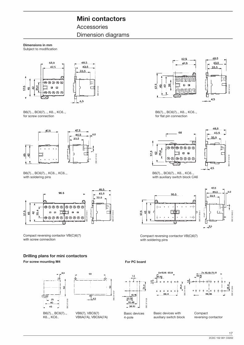
Minicontactors AccessoriesDimension diagrams
DimensionsinmmSubject to modification
B6(7).., BC6(7).., K6.., KC6..,for flat pin connection
B6(7).., BC6(7)..., K6.., KC6..,for screw connection
Compact reversing contactor VB(C)6(7)with screw connection
Compact reversing contactor VB(C)6(7)with soldering pins
B6(7).., BC6(7).., KC6.., KC6..,with soldering pins
B6(7).., BC6(7).., K6.., KC6..,with auxiliary switch block CA6
DrillingplansforminicontactorsForscrewmountingM4 ForPCboard
Basic devices4-pole
Basic devices with auxiliary switch block
Compact reversing contactor
B6(7).., BC6(7).., K6.., KC6..
VB6(7), VBC6(7)VB6A(7A), VBC6A(7A)
BBC
87
6104
-1
BBC
87
6106 BB
C 8
7 61
07
BBC
87
6108
BBC
87
6643
BBC
87
6644
BBC
87
6642
-1
BBC
87
6642
-2
4,0
4.0
BBC
87
6103
M

182CDC 102 001 C0202
MinicontactorsAccessoriesDimension diagrams
B6(7)-F mit LB6
BBC
87
6645
4.0min.
Auxiliary switch blocks
BBC
87
6646
CA6
4.0min.
BBC
87
6648
Dimensionsinmm Subject to modification
CA6-F
SST
203
98
BBC
87
6647
BBC
87
6649
4.0min.
CA6-P CA6 with LB6-CA
B(C)6, B(C)7, K(C)6 with screwed-on auxiliary switch block CAF6
SST
210
94 M
CAF6
SST
211
94 M
B6(7) with T7DU
192CDC 102 001 C0202
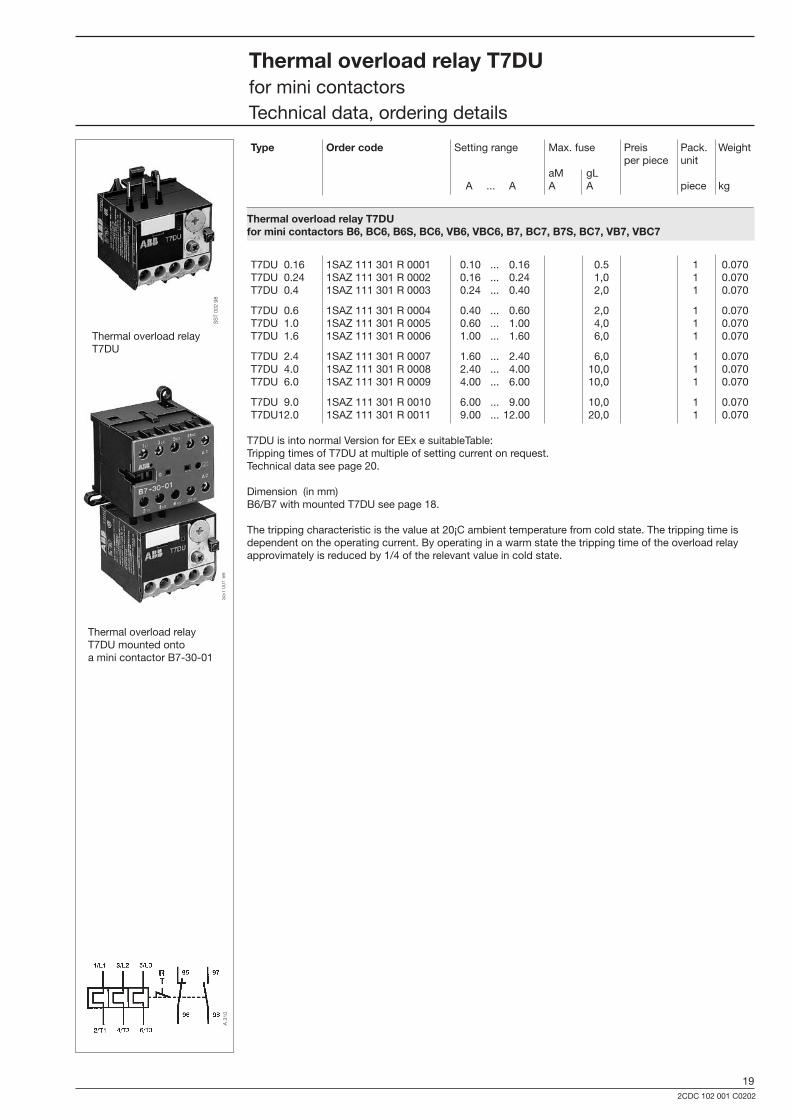
ThermaloverloadrelayT7DUfor mini contactors Technical data, ordering details
Type Ordercode Setting range Max. fuse Preis Pack. Weight per piece unit aM gL A ... A A A piece kg
ThermaloverloadrelayT7DU forminicontactorsB6,BC6,B6S,BC6,VB6,VBC6,B7,BC7,B7S,BC7,VB7,VBC7
T7DU 0.16 1SAZ 111 �01 R 0001 0.10 ... 0.16 0.5 1 0.070 T7DU 0.24 1SAZ 111 �01 R 0002 0.16 ... 0.24 1,0 1 0.070 T7DU 0.4 1SAZ 111 �01 R 000� 0.24 ... 0.40 2,0 1 0.070
T7DU 0.6 1SAZ 111 �01 R 0004 0.40 ... 0.60 2,0 1 0.070 T7DU 1.0 1SAZ 111 �01 R 0005 0.60 ... 1.00 4,0 1 0.070 T7DU 1.6 1SAZ 111 �01 R 0006 1.00 ... 1.60 6,0 1 0.070
T7DU 2.4 1SAZ 111 �01 R 0007 1.60 ... 2.40 6,0 1 0.070 T7DU 4.0 1SAZ 111 �01 R 0008 2.40 ... 4.00 10,0 1 0.070 T7DU 6.0 1SAZ 111 �01 R 0009 4.00 ... 6.00 10,0 1 0.070
T7DU 9.0 1SAZ 111 �01 R 0010 6.00 ... 9.00 10,0 1 0.070 T7DU12.0 1SAZ 111 �01 R 0011 9.00 ... 12.00 20,0 1 0.070
T7DU is into normal Version for EEx e suitableTable:Tripping times of T7DU at multiple of setting current on request. Technical data see page 20.
Dimension (in mm)B6/B7 with mounted T7DU see page 18.
The tripping characteristic is the value at 20¡C ambient temperature from cold state. The tripping time is dependent on the operating current. By operating in a warm state the tripping time of the overload relay approvimately is reduced by 1/4 of the relevant value in cold state.
Thermal overload relay T7DU
Thermal overload relay T7DU mounted onto a mini contactor B7-�0-01
SS
T 00
1 98
SS
T 00
2 98
A 3
10

202CDC 102 001 C0202
Technicaldata
Ratedinsulationvoltage Ui 690 V
Permissibleambienttemperature °C -25 ... +50 open temperature-compensated Storage temperature °C -40 ... +70
Mountingposition ±�0° referred to vertical mounting position not horizontal, not upside down, 5 mm lateral clearance for side-by-side mounting
Switchingfrequency with avoidance of premature tripping max. ops./h 15
² 40 % relative duty max. ops./h 60 (if 6 x In starting time ² 1s)
Loadratingofauxiliaryswitches Type T 7 DU
NC NO 95-96 97-98
Ratedoperatingvoltage Ue V 500 500
Thermal continuous current A 6 6
Ratedoperatingvoltage Ie at AC-15 220 to 240 V A 1.5 1.5
at AC-15 �80 to 415 V A 0.7 0.5
at AC-15 to 500 V A 0.5 0.�
In the case of DC-15 220 V A 0.2 0.2
ThermaadrelayT7DUfor mini contactors Technical data, ordering details
Settingknobfor motor rated current
b Reset:Manual "manual reset" PositionA: Auto "without manual reset" PositionH:Reset off
Testknob
Time-current curves (mean values), for thermal overload relay T7DU, 0.1 ... 12 A.
SS
T 20
1 98
K
b
NO 97 NC 95
NO 98 NC 96
Settingoptions
press
Neutral position
pull
SST 206 98
SS
T 20
6 98
SS
T 20
7 98
SS
T 20
9 98
Bro
chur
e N
o. 2
CD
C 1
02 0
01 C
0202
Prin
ted
in th
e Fe
dera
l Rep
ublic
of G
erm
any
(05/
07 •
1 •
GV
D)
Sub
ject
to m
odifi
catio
n
ABBABB Global Contact Directory
The ABB Contact Directory (http://www.abb.com/contacts/) helps you find local contacts for ABB products in your country. Please select the relevant product group from the dropdown menu to the right or from the page.
ABB STOTZ-KONTAKT GmbHP. O. Box 10 16 80D-69006 HeidelbergTelephone: ++49 62 21 / 701-0Telefax: ++49 62 21 / 701-723http://www.abb.de/stotzkontakt
Mini ContactorsType B6, B7