technical brochure solenoid valves for r410a & …mopd liquid 2) pb min. 10 w.a.c. 12 w.a.c. 20...
TRANSCRIPT

www.danfoss.com
Technical brochure
Solenoid valves for R410A & R744 (CO2)EVR 2, 3 and 6, EVRH 10 to 20
MAKING MODERN LIVING POSSIBLE

Technical brochure Solenoid Valves for R410A and R744 (CO2), EVR 2, 3 & 6, EVRH 10 to 20 Normally Closed
2 DKRCC.PD.B00.B3.02 / 520H1021 © Danfoss A/S (AC-SMC / MWA), 08 - 2011

Technical brochure Solenoid Valves for R410A and R744 (CO2), EVR 2, 3 & 6, EVRH 10 to 20 Normally Closed
© Danfoss A/S (AC-SMC / MWA), 08 - 2011 DKRCC.PD.B00.B3.02 / 520H1021 3
Contents PageIntroduction ...............................................................................................................................................................................4Features .......................................................................................................................................................................................4Approvals ....................................................................................................................................................................................4Technical data ............................................................................................................................................................................4Ordering ......................................................................................................................................................................................5
Capacity R410A SI unit ...........................................................................................................................................................5 Liquid capacity R410A SI unit ......................................................................................................................................5 Suction vapour capacity R410A SI unit ....................................................................................................................6 Hot gas capacity kW R410A SI unit ............................................................................................................................7
Capacity R410A US unit..........................................................................................................................................................8 Liquid capacity R410A US unit ....................................................................................................................................8 Suction vapour capacity R410A US unit ..................................................................................................................8 Hot gas capacity R410A US unit .................................................................................................................................9
Capacity R744 (CO2) .................................................................................................................................................................9
Design / function ....................................................................................................................................................................10Material specifications ..........................................................................................................................................................11Dimension and weights .......................................................................................................................................................11

Technical brochure Solenoid Valves for R410A and R744 (CO2), EVR 2, 3 & 6, EVRH 10 to 20 Normally Closed
4 DKRCC.PD.B00.B3.02 / 520H1021 © Danfoss A/S (AC-SMC / MWA), 08 - 2011
Type
Opening differential pressure with standard coil
∆p bar kv value 1)
m3/h
Temperature of medium
Refrigerant
Max. working pressure
PBMax. (MOPD liquid 2)
Min.10
w.a.c.12
w.a.c.20
w.a.c.20
w.d.c. -40°C → +105°C for 10 or 12 w coil
Max. 130°C during defrost
-40°C → 80°C for 20 watt coil
R410AR744 (CO
2)
HCFCHFC
45.2 barg
EVR 2 0.0 25 25 38 18 0.16
EVR 3 0.0 21 25 38 18 0.27
EVR 6 0.05 21 25 38 18 0.8
EVRH 10 0.05 21 25 38 18 1.9
EVRH 15 0.05 21 25 38 18 2.6
EVRH 20 (a.c.) 0.05 21 25 38 5.0
EVRH 20 (d.c.) 0.05 16 5.0
EVRH high pressure range is a direct or servo operated solenoid valve specially designed to meet the requirements for high pressure refrigerants as R410A and R744 (CO2). The EVRH valve can be used for liquid, suction and hot gas lines
Introduction
• Normally closed• Wide choice of coils for a.c. and d.c. voltage • Suitable for R410A and R744 (CO2)• Designed for media temperatures up to +105°C / 221°F
• Design pressure 45.2 barg / 655 psig• MOPD up to 38 bar / 550 psi with 20 watt coil• Solder connection up to 7/8 inch • Extended ends for soldering• It is not necessary to dismantle the valve during soldering.
The Low Voltage Directive (LVD) 73/23/EC with amendments EN 60730-2-8.
Features
Approvals
Technical data
SI unit
1) The kv value is the water flow in m3/h at a pressure drop across the valve of 1 bar ρ = 1000 kg/m3
2) MOPD for media in gas form is approx. 1bar greater
US unit
Type
Opening differential pressure with standard coil
∆p psi Cv value 3)
gal/min
Temperature of medium
Refrigerant
Max. working pressure
MWPMax. (= MOPD) liquid 4)
Min. 10 w 12 w 20 w 20 w-40°F → +220°F for 10
or 12 w coilMax. 266°F during
defrost
-40°F → 176°F for 20 watt coil
R410AR744 (CO
2)
HCFCHFC
655 psig
EVR 2 0.0 360 360 550 550 0.19
EVR 3 0.0 305 360 550 260 0.32
EVR 6 0.7 305 360 550 260 0.93
EVRH 10 0.7 305 360 550 260 2.2
EVRH 15 0.7 305 360 550 260 3.0
EVRH 20 (a.c.) 0.7 305 360 550 5.8
EVRH 20 (d.c.) 0.7 230 5.8
3) The Cv value is the water flow in gal/min at a pressure drop across the valve of 1 psi ρ = 10 lbs/gal
4) MOPD for media in gas form is approx. 14.5 psi greater.
Ambient temperature and enclosure for coil:see “coils for solenoid valve”, DKRCC.PD.BS0.A

Technical brochure Solenoid Valves for R410A and R744 (CO2), EVR 2, 3 & 6, EVRH 10 to 20 Normally Closed
© Danfoss A/S (AC-SMC / MWA), 08 - 2011 DKRCC.PD.B00.B3.02 / 520H1021 5
EVR 2
a.c. / d.c.
1/4 6 032F1201 032F1202
EVR 3 3/8 10 032F1204 032F1208
EVR 3 1/4 6 032F1206 032G1207
EVR 6 3/8 10 032F1212 032F1213
EVR 6 1/2 12 032F1209 032F1236
EVRH 10 1/2 12 032G1054 032G1055
EVRH 15 5/8 16 032G1056 032G1056
EVRH 20 a.c. 7/8 22 032G1057 032G1057
EVRH 20 d.c. 7/8 22 032G1058 032G1058
EVR 2 2.59 3.66 4.48 5.18 5.79
EVR 3 4.37 6.18 7.56 8.75 9.77
EVR 6 13.0 18.3 22.4 25.9 29.0
EVRH 10 30.8 43.5 53.2 61.5 68.9
EVRH 15 42.1 59.5 72.8 84.2 94.1
EVRH 20 81.0 114.5 140.0 162 181.0
tf ºC -10 0 10 15 20 25 30 35 40 45 50
R410A 0.73 0.79 0.86 0.9 0.95 1 1.06 1.14 1.23 1.33 1.47
Ordering Solenoid valve - Normally closed (NC) - Soldering ODF without manual stem - without coil
TypeRequired coil
typeConnection Code no.
in. mm in. mm
CoilsSee “coils for solenoid valve”, DKRCC.PD.BS0.A
Capacity R410A SI units Liquid capacity Qc kW
TypeLiquid capacity Qc at pressure drop across valve ∆p bar
0.1 0.2 0.3 0.4 0.5
R410A
Capacities are based on:Liquid temperature t
l = +25°C ahead of the valve
Evaporarating temperature te = -10°C
Superheat 0 K
Correction factorsWhen sizing valves, the plant capacity must be multiplied by a correction factor depending on liquid temperature t
l ahead of the valve/
evaporator. When the corrected capacity is known, the selection can be made from the table.
Correction factors for liquid temperature tl
Note:EVRH 4, 8, 18, 22, 25, 32 and 40 for R410A and R744 can be supplied on request. Please contact Danfoss
Technical brochure Solenoid Valves for R410A and R744 (CO2), EVR 2, 3 & 6, EVRH 10 to 20 Normally Closed
6 DKRCC.PD.B00.B3.02 / 520H1021 © Danfoss A/S (AC-SMC / MWA), 08 - 2011
EVR 20.100.150.20
0.200.240.28
0.250.300.35
0.310.370.43
0.370.460.53
0.450.550.63
0.530.650.75
EVR 30.100.150.20
0.330.410.47
0.420.510.59
0.520.630.73
0.630.770.89
0.760.921.07
0.901.101.27
EVR 60.100.150.20
0.991.201.39
1.251.521.76
1.541.872.16
1.872.292.64
2.242.743.17
2.673.263.76
EVRH 100.100.150.20
2.362.853.31
2.963.614.18
3.654.455.13
4.455.436.27
5.326.507.52
6.357.758.93
EVRH 150.100.150.20
3.223.904.52
4.064.945.72
5.006.087.02
6.087.448.58
7.288.8910.3
8.6810.612.2
EVRH 200.100.150.20
6.207.508.70
7.809.5011.0
9.6011.713.5
11.714.316.5
14.017.119.8
16.720.423.5
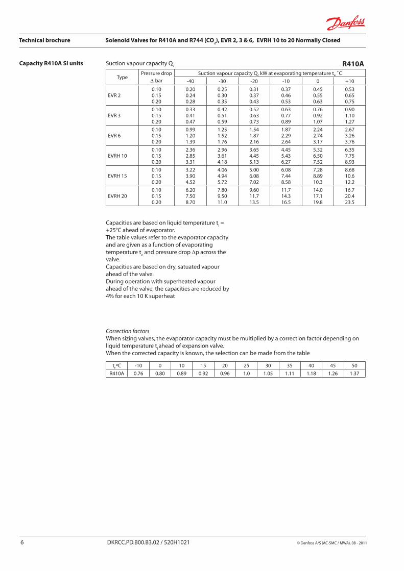
tf ºC -10 0 10 15 20 25 30 35 40 45 50
R410A 0.76 0.80 0.89 0.92 0.96 1.0 1.05 1.11 1.18 1.26 1.37
Capacity R410A SI units Suction vapour capacity Qc
TypePressure drop
∆ barSuction vapour capacity Qc kW at evaporating temperature te ˚C
-40 -30 -20 -10 0 +10
Capacities are based on liquid temperature tl =
+25°C ahead of evaporator.The table values refer to the evaporator capacity and are given as a function of evaporating temperature t
e and pressure drop ∆p across the
valve.Capacities are based on dry, satuated vapour ahead of the valve.During operation with superheated vapour ahead of the valve, the capacities are reduced by 4% for each 10 K superheat
Correction factorsWhen sizing valves, the evaporator capacity must be multiplied by a correction factor depending on liquid temperature t
l ahead of expansion valve.
When the corrected capacity is known, the selection can be made from the table
R410A

Technical brochure Solenoid Valves for R410A and R744 (CO2), EVR 2, 3 & 6, EVRH 10 to 20 Normally Closed
© Danfoss A/S (AC-SMC / MWA), 08 - 2011 DKRCC.PD.B00.B3.02 / 520H1021 7
EVR 2
0.100.200.40.81.6
0.540.771.091.542.17
0.560.791.111.572.22
0.560.791.121.582.24
0.550.771.091.552.19
0.510.721.021.462.04
EVR 3
0.100.200.40.81.6
0.921.301.842.593.66
0.941.331.882.663.75
0.951.331.892.673.78
0.931.311.852.613.69
0.861.221.722.463.45
EVR 6
0.100.200.40.81.6
2.723.845.447.68
10.85
2.783.945.577.8711.1
2.803.955.6
7.9211.2
2.753.875.477.7310.9
2.563.605.107.3010.2
EVRH 10
0.100.200.40.81.6
6.469.1212.918.225.7
6.619.3513.218.726.4
6.659.3913.318.826.6
6.549.2013.018.326.0
6.088.5512.117.324.2
EVRH 15
0.100.200.40.81.6
8.8412.517.725.035.3
9.0512.818.125.636.1
9.1012.818.225.736.4
8.9412.617.825.135.6
8.3211.716.623.733.2
EVRH 20
0.100.200.40.81.6
17.024.034.048.067.8
17.424.634.849.269.5
17.524.735.049.570.0
17.224.234.248.368.4
16.022.531.945.663.8
tf ºC -40 -30 -20 -10 0 +10
R410A 0.92 0.95 0.98 1.0 1.02 1.03
R410AHot gas capcity Qh kW
Type
Pressure drop
∆p bar
Evaporating temp. te -10˚C, hot gas temp. th = tc +25˚C, Subcooling ∆tsub = 4K
Condensing temperataure tc ˚C
+20 +30 +40 +50 +60
An increase in hot gas temperature th of 10 K,
based on th = t
c + 25°C reduces valve capacity
approx. 2% and vice versa.
A change in evaporating temperature te changes
valve capacity: see correction factor table below.
Correction factorsWhen sizing valves, the table value must be multiplied by a correction factor depending on evaporting temperature t
e.
Correction factors for liquid temperature tl
An increase in hot gas temperature th
of 10 K reduces valve capacity approx 2% and vice versa.
Capacity R410A SI units

Technical brochure Solenoid Valves for R410A and R744 (CO2), EVR 2, 3 & 6, EVRH 10 to 20 Normally Closed
8 DKRCC.PD.B00.B3.02 / 520H1021 © Danfoss A/S (AC-SMC / MWA), 08 - 2011
EVR 2 0.56 0.78 0.96 1.10 1.23 1.35 1.46EVR 3 0.98 1.37 1.68 1.93 2.15 2.36 2.55EVR 6 2.79 3.92 4.80 5.52 6.16 6.75 7.30EVRH 10 6.63 9.31 11.4 13.1 14.6 16.0 17.3EVRH 15 9.07 12.7 15.6 17.9 20.0 21.9 23.7EVRH 20 17.5 24.5 30.0 34.5 38.5 42.2 45.6
EVR 2123
0.040.060.07
0.050.070.09
0.070.090.12
0.070.110.13
0.080.120.14
0.090.130.16
0.100.140.18
0.110.160.19
EVR 3123
0.070.100.12
0.090.130.16
0.120.160.20
0.130.180.23
0.140.210.25
0.160.230.28
0.180.250.31
0.200.280.34
EVR 6123
0.200.290.35
0.260.370.46
0.330.470.58
0.370.530.65
0.410.590.72
0.460.650.80
0.510.720.88
0.560.790.97
EVRH 10123
0.480.680.84
0.620.881.08
0.791.121.37
0.891.251.54
0.981.391.71
1.091.541.89
1.201.702.09
1.331.872.30
EVRH 15123
0.660.931.14
0.851.211.48
1.091.531.88
1.211.722.10
1.351.912.33
1.502.112.59
1.652.332.85
1.812.563.14
EVRH 20123
1.271.792.20
1.642.322.85
2.092.953.61
2.333.304.04
2.593.674.49
2.884.064.98
3.174.485.49
3.494.936.04
Capacity R410A US unit Liquid capacity Q0 tons R410A
TypeLiquid capacity Q
0 tons at pressure drop across valve ∆p psi
1 2 3 4 5 6 7
Capacities are based on:liquid temperature t
l = 100°F
Evaporating temperature te = 40°F
Superheat 10°F
Correction factors for liquid temperature tl
When liquid temperature tl ahead of the
expansion valve is other than 100°F, adjust the table capacities by multiplying them by the appropriate correction factor found in the following table.
tl˚F 80 90 100 110 120
Factor 1.10 1.05 1.00 0.95 0.90
Suction vapour capacity Q0
TypePressure drop
∆p psiSuction vapour capacity Q0 tons at evaporating temperature te ˚F
-40 -20 0 +10 +20 +30 +40 +50
R410A
Note: Bold figures refer to rated capacity
The table values refer to evaporator capacity and are given as a function of evaporating temperature t
e and pressure drop ∆p across the
valve.Capacities are based on liquid temperature t
l
= 100 °F ahead of the expansion valve and superheat t
s = 7°F
For each additional 10°F of superheat, the table capacities must be reduced by 2%.
Correction factors for liquid temperature tl
When liquid temperature tl ahead of the
expansion valve is other than 100°F, adjust the table capacities by multiplying them by the appropriate correction factor found in the following table
tl˚F 80 90 100 110 120
Factor 1.10 1.05 1.00 0.95 0.90
Note: Bold figures refer to rated capacity

Technical brochure Solenoid Valves for R410A and R744 (CO2), EVR 2, 3 & 6, EVRH 10 to 20 Normally Closed
© Danfoss A/S (AC-SMC / MWA), 08 - 2011 DKRCC.PD.B00.B3.02 / 520H1021 9
EVR 2
25
10152025
0.190.300.420.520.600.67
0.200.310.440.540.620.69
0.180.290.410.500.580.65
EVR 3
25
10152025
0.330.520.740.901.041.16
0.340.540.760.941.081.21
0.320.500.710.871.011.13
EVR 6
25
10152025
0.941.492.112.592.983.34
0.981.552.192.683.103.46
0.911.442.042.502.883.23
EVRH 10
25
10152025
2.243.545.026.147.087.92
2.333.685.206.367.368.22
2.173.424.855.936.847.66
EVRH 15
25
10152025
3.074.856.868.409.6910.8
3.185.037.118.7010.011.2
2.964.686.648.119.3610.5
EVRH 20
25
10152025
5.909.3213.216.118.620.8
6.129.6813.716.719.321.6
5.709.0012.715.618.020.1
Capacity R410A US unit Hot gas capacity Qh
tons
Type
Pressure drop
∆p psi
Evaporating temp. te=+40˚F, hotgas temp. th=tc+40˚F, Subcooling tu=10˚F
Condensing temperature tc˚F
+70 +100 +140
Correction factors for th and t
c
The table values refer to hot gas capacity and are given as a function of condensing temperature t
c
and pressure drop ∆p across the valve.Capacities are based on a hot gas temperature superheated 40°F above condensing temperature (t
h= t
c + 40°F).
For each additional 10°F of superheat above 40°F, the table capacities must be reduced by 1%.
Due to the fact that EVRH only can be used for sub critical CO
2 application, capacity tables are not
illustrated in this catalog. For capacity dimension please refer to DIR-Calc or contact your local Danfoss office.
When the valve is used in a hot gas defrost circuit, evaporatore temperature affects the capacity. When the evaporator temperature differs from +40°F, adjust the table capacities by multiplying them by the appropriate correction factor found in the following table.
tl˚F -40 -20 0 20 40 50
Factor 1.18 1.14 1.09 1.04 1 0.97
Capacity R744 (CO2)

Technical brochure Solenoid Valves for R410A and R744 (CO2), EVR 2, 3 & 6, EVRH 10 to 20 Normally Closed
10 DKRCC.PD.B00.B3.02 / 520H1021 © Danfoss A/S (AC-SMC / MWA), 08 - 2011
Design/ Function
4. Coil16. Armature18. Valve plate/ Pilot valve plate20. Earth terminal24. Connection for flexible steel hose28. Gasket29. Pilot orifice
36. DIN plug37. DIN socket (to DIN 43650)40. Protective cap/ Terminal box43. Valve cover
45. Valve cover gasket49. Valve body
73. Equalization hole
80. Diaphragm/ Servo piston83. Valve seat
90. Mounting hole EVRH solenoid valves are designed on two different principles:1. Direct operation2. Servo operation
1. Direct operationEVR2 and 3 are direct operated. The valve opens direct for full flow when the armature (16) moves up into the magnetic field of the coil.This means that the valve operates with a min. differential pressur of 0 bar.The teflon valve plate (18) is fitted direct on the armature (16).Inlet pressure acts from above on the armature and the valve plate. Thus inlet pressure, spring force and the weight of armature act to close the valve when the coil is currentless.
2. Servo operationEVR 6 and EVRH 10-20 are servo operated with a “floating” diaphragm (80). The pilot orifice (29) of stainless steel is placed in the centre of the diaphragm. The teflon pilot valve plate (18) is
fitted direct to the armature (16). When the coil is currentless, the main orifice and pilot orifice are closed. The pilot orifice and main orifice are held closed by the weight of the armature, the armature spring force and the differential pressure between inlet and outlet sides.
When current is applied to the coil the armature is drawn up into the magnetic field and opens the pilot orifice. This relieves the pressure above the diaphragm i.e. the space above the diaphragm becomes connected to the outlet side of the valve. The differential pressure between inlet and outlet sides then presses the diaphragm away from the main orifice and opens it for full flow. Therefore a certain minimum differential pressure is necessary to open the valve and keep it open. For EVR 6 and EVRH 10 to 20 valves this differential pressure is 0.05 bar.
When current is switched off, the pilot orifice closes. Via the equalization holes (73) in the diaphragm, the pressure above the diaphragm then rises to the same value as the inlet pressure and the diaphragm closes the main orifice.

Technical brochure Solenoid Valves for R410A and R744 (CO2), EVR 2, 3 & 6, EVRH 10 to 20 Normally Closed
© Danfoss A/S (AC-SMC / MWA), 08 - 2011 DKRCC.PD.B00.B3.02 / 520H1021 11
EVR 2 & 3 1/4 6 14 64 9 102 7 33 0.2
EVR 6 3/8 10 14 75 10 111 9 36 0.3
EVRH 10 1/2 12 16 76 10 127 10 46 0.5
EVRH 15 5/8 16 19 83 176 12 56 0.8
EVRH 20 7/8 22 20 87 191 17 72 1.0
EVR 2 & 3 1/4 6 9/16 2 1/2 5/16 4 9/32 1 5/16 0.44
EVR 6 3/8 10 9/16 3 3/8 4 3/8 3/8 1 7/16 0.66
EVRH 10 1/2 12 5/8 3 7/16 5 3/8 1 13/16 1.10
EVRH 15 5/8 16 3/4 3 1/4 3/4 6 15/16 1/2 2 3/16 1.75
EVRH 20 7/8 22 25/32 3 7/16 7 1/2 5/8 2 13/16 2.21
EVR 2 to 6 EVRH 10 to 20
Material specifications
Solenoid valve Standard
No. Description Type Material Analysis Mat. no. W. no. DIN EN
1 Valve body EVR 2 to 6 and EVRH 10 → 20 Brass CuZn40Pb2 CW617N 2.0402 17672-1 12165
2 CoverEVR 2 to 6 Stainless steel X5CrNi18-10 1.4301 10088
EVRH 10 → 20 Brass CuZn40Pb2 CW617N 2.0402 17672-1 12165
3 Armature tube EVR 2 to 6 and EVRH 10 → 20 Stainless steel X2CrNi19-11 1.4306 10088
5 Gasket EVR 2 to 6 and EVRH 10 → 20 Rubber Cr
7 Solder tube EVR 2 to 6 and EVRH 10 → 20 Copper SF-Cu CW024A 2.0090 1787 12449
8 Screws EVR 2 to 6 and EVRH 10 → 20 Stainless steel A2-70 3506
Dimensions and weight
TypeConnection solder H1 H2 H3 L L2 B Weight
in. mm mm mm mm mm mm mm kg
TypeConnection solder H1 H2 H3 L L2 B Weight
in. mm in. in. in. in. in. in. lbs
SI unit
SU unit
Technical brochure Solenoid Valves for R410A and R744 (CO2), EVR 2, 3 & 6, EVRH 10 to 20 Normally Closed
12 DKRCC.PD.B00.B3.02 / 520H1021 © Danfoss A/S (AC-SMC / MWA), 08 - 2011