technical brochure check valves for ammonia and
TRANSCRIPT
MAKING MODERN LIVING POSSIBLE
Technical brochure
Check valves for ammonia and fluorinated refrigerantsType NRVA
© Danfoss AC-MCI/MWA), 2013-04 DKRCI.PD.FK0.A3.22 / 521U0094 1
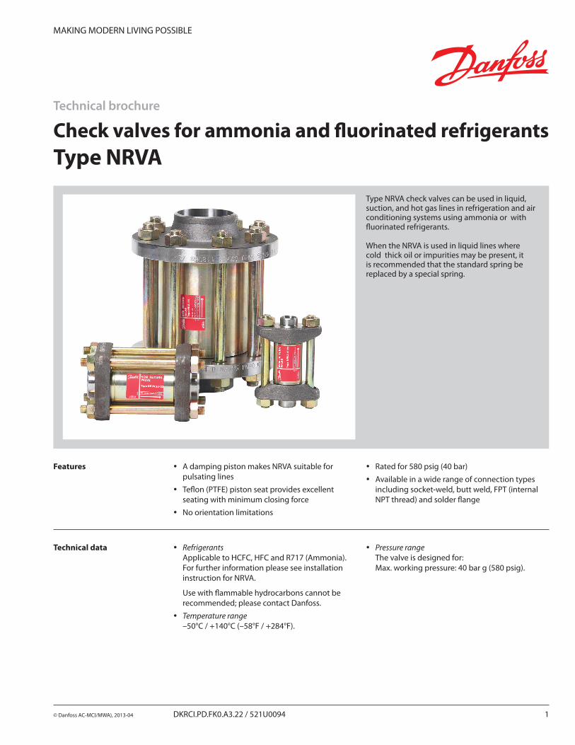
Type NRVA check valves can be used in liquid, suction, and hot gas lines in refrigeration and air conditioning systems using ammonia or with fluorinated refrigerants.
When the NRVA is used in liquid lines where cold thick oil or impurities may be present, it is recommended that the standard spring be replaced by a special spring.
Features y A damping piston makes NRVA suitable for pulsating lines
y Teflon (PTFE) piston seat provides excellent seating with minimum closing force
y No orientation limitations
y Rated for 580 psig (40 bar)
y Available in a wide range of connection types including socket-weld, butt weld, FPT (internal NPT thread) and solder flange
Technical data y Refrigerants Applicable to HCFC, HFC and R717 (Ammonia). For further information please see installation instruction for NRVA. Use with flammable hydrocarbons cannot be recommended; please contact Danfoss.
y Temperature range –50°C / +140°C (–58°F / +284°F).
y Pressure range The valve is designed for: Max. working pressure: 40 bar g (580 psig).
2 DKRCI.PD.FK0.A3.22 / 521U0094 © Danfoss AC-MCI/MWA), 2013-04
Check valves for ammonia and fluorinated refrigerants, Type NRVA
Contents Page
Features . . . . . . . . . . . . . . . . . . . . . . . . . . . . . . . . . . . . . . . . . . . . . . . . . . . . . . . . . . . . . . . . . . . . . . . . . . . . . . . . . . . . . . . . . . . . . . . 1
Technical data . . . . . . . . . . . . . . . . . . . . . . . . . . . . . . . . . . . . . . . . . . . . . . . . . . . . . . . . . . . . . . . . . . . . . . . . . . . . . . . . . . . . . . . . . 1
Material specification . . . . . . . . . . . . . . . . . . . . . . . . . . . . . . . . . . . . . . . . . . . . . . . . . . . . . . . . . . . . . . . . . . . . . . . . . . . . . . . . . . .3
Ordering:
Complete valves . . . . . . . . . . . . . . . . . . . . . . . . . . . . . . . . . . . . . . . . . . . . . . . . . . . . . . . . . . . . . . . . . . . . . . . . . . . . . . . . . . . 4
Valve body without flanges . . . . . . . . . . . . . . . . . . . . . . . . . . . . . . . . . . . . . . . . . . . . . . . . . . . . . . . . . . . . . . . . . . . . . . . . 4
Staybolts and gaskets . . . . . . . . . . . . . . . . . . . . . . . . . . . . . . . . . . . . . . . . . . . . . . . . . . . . . . . . . . . . . . . . . . . . . . . . . . . . . . 4
Flange connections . . . . . . . . . . . . . . . . . . . . . . . . . . . . . . . . . . . . . . . . . . . . . . . . . . . . . . . . . . . . . . . . . . . . . . . . . . . . . . . . 5
Dimensions and weights . . . . . . . . . . . . . . . . . . . . . . . . . . . . . . . . . . . . . . . . . . . . . . . . . . . . . . . . . . . . . . . . . . . . . . . . . . . . . . . 5
Nominal capacities:
Liquid line with/without phase change . . . . . . . . . . . . . . . . . . . . . . . . . . . . . . . . . . . . . . . . . . . . . . . . . . . . . . . . . . 6 - 9
Pumped iquid line . . . . . . . . . . . . . . . . . . . . . . . . . . . . . . . . . . . . . . . . . . . . . . . . . . . . . . . . . . . . . . . . . . . . . . . . . . . . 10 - 12
Dry suction line . . . . . . . . . . . . . . . . . . . . . . . . . . . . . . . . . . . . . . . . . . . . . . . . . . . . . . . . . . . . . . . . . . . . . . . . . . . . . . . 13 - 16
Discharge line . . . . . . . . . . . . . . . . . . . . . . . . . . . . . . . . . . . . . . . . . . . . . . . . . . . . . . . . . . . . . . . . . . . . . . . . . . . . . . . . 17 - 20
© Danfoss AC-MCI/MWA), 2013-04 DKRCI.PD.FK0.A3.22 / 521U0094 3
Check valves for ammonia and fluorinated refrigerants, Type NRVA
Technical data
TypeNominal size
Dp (see note 2)
kv value(see note 3)
Cv value (see note 4)
With standard spring
With special spring
(see note 1)
in. bar psig bar psig m3/h gal/min
NRVA 15 1/2 0.12 1.7 0.3 4.4 5 6
NRVA 20 3/4 0.12 1.7 0.3 4.4 6 7
NRVA 25 1 0.12 1.7 0.3 4.4 19 22
NRVA 32 11/4 0.12 1.7 0.3 4.4 20 23
NRVA 40 11/2 0.07 1.0 0.4 5.8 44 51
NRVA 50 2 0.07 1.0 0.4 5.8 44 51
NRVA 65 21/2 0.07 1.0 0.4 5.8 75 871) A special spring can be supplied to replace the standard valve spring.2) Dp = minimum pressure differential at which the valve is completely open.3) The kv value is the flow of water in m3/h at a pressure drop across valve of 1 bar, ρ = 1000 kg/3.4) The Cv value is the flow of water in gal/min at a pressure drop across valve of 1 psig, ρ = 10 lbs/gal.
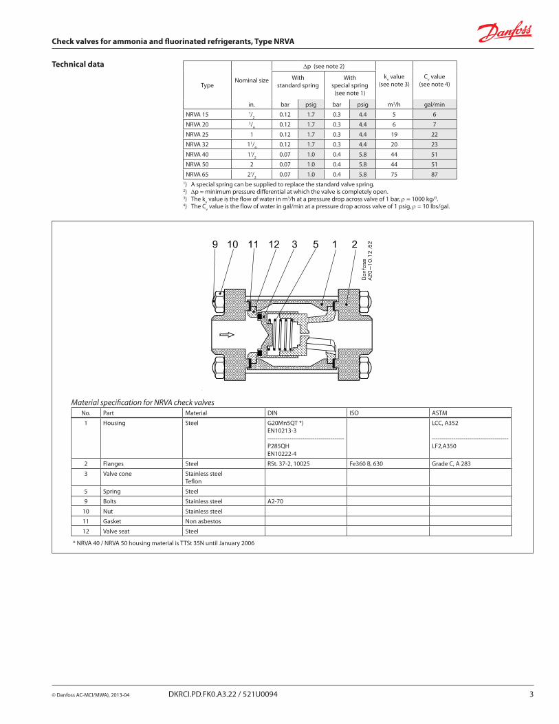
Material specification for NRVA check valvesNo. Part Material DIN ISO ASTM
1 Housing Steel G20Mn5QT *)EN10213-3---------------------------------------P285QHEN10222-4
LCC, A352
---------------------------------------LF2,A350
2 Flanges Steel RSt. 37-2, 10025 Fe360 B, 630 Grade C, A 283
3 Valve cone Stainless steelTeflon
5 Spring Steel
9 Bolts Stainless steel A2-70
10 Nut Stainless steel
11 Gasket Non asbestos
12 Valve seat Steel
* NRVA 40 / NRVA 50 housing material is TTSt 35N until January 2006
4 DKRCI.PD.FK0.A3.22 / 521U0094 © Danfoss AC-MCI/MWA), 2013-04
Check valves for ammonia and fluorinated refrigerants, Type NRVA
To be continued next page.
Type Code no.
NRVA 15 020-2020
NRVA 20 020-2020
NRVA 25 020-2022
NRVA 32 020-2022
NRVA 40 020-2024
NRVA 50 020-2024
NRVA 65 020-2026
Staybolts and gaskets
Type Dimensions Code no.
NRVA 15 / 20 M 12 × 115 mmQuantity: 2 006-1107
NRVA 25 / 32 M 12 × 148 mmQuantity: 4 006-1135
NRVA 40 / 50 M 12 × 167 mmQuantity: 4 006-1137
NRVA 65 M 16 × 200 mmQuantity: 8 006-1138
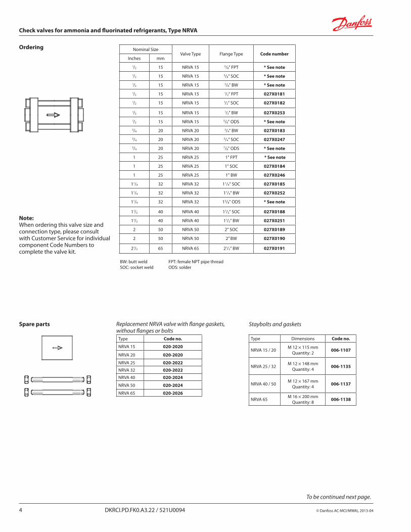
Ordering Nominal SizeValve Type Flange Type Code number
Inches mm
1/2 15 NRVA 15 3/8" FPT * See note
1/2 15 NRVA 15 3/8" SOC * See note
1/2 15 NRVA 15 3/8" BW * See note
1/2 15 NRVA 15 1/2" FPT 027X0181
1/2 15 NRVA 15 1/2" SOC 027X0182
1/2 15 NRVA 15 1/2" BW 027X0253
1/2 15 NRVA 15 5/8" ODS * See note
3/4 20 NRVA 20 3/4" BW 027X0183
3/4 20 NRVA 20 3/4" SOC 027X0247
3/4 20 NRVA 20 7/8" ODS * See note
1 25 NRVA 25 1" FPT * See note
1 25 NRVA 25 1" SOC 027X0184
1 25 NRVA 25 1" BW 027X0246
11/4 32 NRVA 32 11/4" SOC 027X0185
11/4 32 NRVA 32 11/4" BW 027X0252
11/4 32 NRVA 32 13/8" ODS * See note
11/2 40 NRVA 40 11/2" SOC 027X0188
11/2 40 NRVA 40 11/2" BW 027X0251
2 50 NRVA 50 2" SOC 027X0189
2 50 NRVA 50 2” BW 027X0190
21/2 65 NRVA 65 21/2" BW 027X0191
Spare parts
BW: butt weld FPT: female NPT pipe threadSOC: socket weld ODS: solder
Replacement NRVA valve with flange gaskets, without flanges or bolts
Note: When ordering this valve size and connection type, please consult with Customer Service for individual component Code Numbers to complete the valve kit.
© Danfoss AC-MCI/MWA), 2013-04 DKRCI.PD.FK0.A3.22 / 521U0094 5
Check valves for ammonia and fluorinated refrigerants, Type NRVA
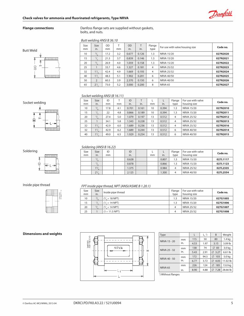
Flange connections Danfoss flange sets are supplied without gaskets, bolts, and nuts.
Butt Weld
Socket welding
Butt welding ANSI B 36.10Sizemm
Sizein.
ODmm
Tmm
ODin.
Tin.
Flange type For use with valve housing size Code no.
10 3/8 17.2 3.2 0.677 0.126 1.3 NRVA 15/20 027N2020
15 1/2 21.3 3.7 0.839 0.146 1.3 NRVA 15/20 027N2021
20 3/4 26.9 4.0 1.059 0.158 1.3 NRVA 15/20 027N2022
25 1 33.7 4.6 1.327 0.181 4 NRVA 25/32 027N2023
32 11/4 42.4 4.9 1.669 0.193 4 NRVA 25/32 027N2024
40 11/2 48.3 5.1 1.902 0.201 6 NRVA 40/50 027N2025
50 2 60.3 3.9 2.370 0.150 6 NRVA 40/50 027N2026
65 21/2 73.0 5.2 3.000 0.200 8 NRVA 65 027N2027
Socket welding ANSI (B 16.11)Sizemm
Sizein.
IDmm
Tmm
IDin.
Tin.
Lmm
Lin.
Flangetype
For use with valve housing size Code no.
10 3/8 17.8 4.1 0.701 0.161 10 0.394 1.3 NRVA 15/20 027N2010
15 1/2 22 4.8 0.866 0.189 10 0.394 1.3 NRVA 15/20 027N2011
20 3/4 27.4 5.0 1.079 0.197 13 0.512 4 NRVA 25/32 027N2012
25 1 34.1 5.8 1.343 0.228 13 0.512 4 NRVA 25/32 027N2013
32 11/4 42.9 6.0 1.689 0.236 13 0.512 4 NRVA 25/32 027N2016
32 11/4 42.9 6.2 1.689 0.244 13 0.512 6 NRVA 40/50 027N2014
40 11/2 49.0 6.5 1.929 0.254 13 0.512 6 NRVA 40/50 027N2015
Soldering Soldering (ANSI B 16.22)
Sizemm
Sizein.
IDmm
IDin.
Lmm
Lin.
Flange type
For use with valve housing size Code no.
5/8 0.628 0.807 1.3 NRVA 15/20 027L11177/8 0.878 0.866 1.3 NRVA 15/20 027L1123
13/8 1.375 0.984 4 NRVA 25/32 027L2335
21/8 2.125 1.300 4 NRVA 40/50 027L2554
Inside pipe thread FPT inside pipe thread, NPT (ANSI/ASME B 1.20.1)Sizemm
Sizein. Inside pipe thread Flange
typeFor use with valve housing size Code no.
10 3/8 (3/8 × 18 NPT) 1.3 NRVA 15/20 027G1005
15 1/2 (1/2 × 14 NPT) 1.3 NRVA 15/20 027G1006
20 3/4 (3/4 × 14 NPT) 4 NRVA 25/32 027G1007
25 1 (1 × 11.5 NPT) 4 NRVA 25/32 027G1008
Dimensions and weights Type L L1 1) B Weight
NRVA 15 - 20 mmin.
115 50 80 1.4 kg
4.53 1.97 3.15 3.09 lb
NRVA 25 - 32 mmin.
138 74 ∅ 83 3.0 kg
5.43 2.91 ∅ 3.27 6.61 lb
NRVA 40 - 50 mmin.
172 94.5 ∅ 103 5.0 kg
6.77 3.72 ∅ 4.05 11.02 lb
NRVA 65 mm
in.
226 124 ∅ 185 13.0 kg
8.90 4.88 ∅ 7.28 28.66 lb1) Without flanges
6 DKRCI.PD.FK0.A3.22 / 521U0094 © Danfoss AC-MCI/MWA), 2013-04
Check valves for ammonia and fluorinated refrigerants, Type NRVA
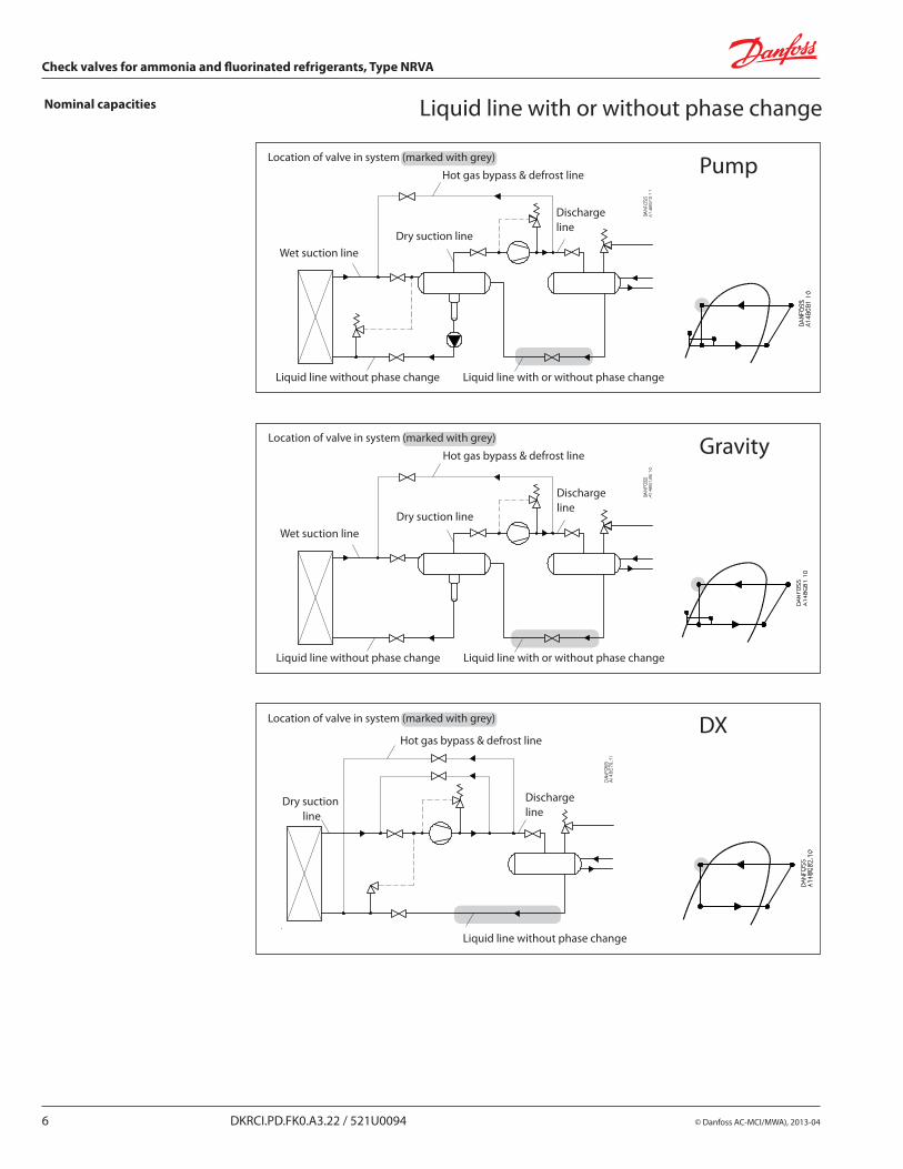
PumpLocation of valve in system (marked with grey)
Hot gas bypass & defrost line
Discharge line
Wet suction lineDry suction line
Liquid line without phase change Liquid line with or without phase change
Nominal capacities Liquid line with or without phase change
GravityLocation of valve in system (marked with grey)
Hot gas bypass & defrost line
Discharge line
Wet suction lineDry suction line
Liquid line without phase change Liquid line with or without phase change
DXLocation of valve in system (marked with grey)
Hot gas bypass & defrost line
Discharge line
Liquid line without phase change
Dry suction line
© Danfoss AC-MCI/MWA), 2013-04 DKRCI.PD.FK0.A3.22 / 521U0094 7
Check valves for ammonia and fluorinated refrigerants, Type NRVA
Liquid line with or without phase change
Calculation example (R-134a capacities):
Running conditions in a plant are as follows: Te = –20°F Qo = 130 TR Tliq = 50°F Max. DP = 5 psi
The capacity table is based on nominal conditions (DP = 3 psi, Tliq = 90°F)
The actual capacity must therefore be corrected to a nominal condition by multiplication with correction factors.
Correction factor for DP 5 psi, fDP = 0.79Correction factor for liquid temperature fTliq = 0.81.
Qn = Qo × fDP × fTliq = 130 × 0.79 × 0.81 = 83.2 TR
From the capacity table a NRVA 25 with Qn = 100 TR is the correct selection for the application.
Nominal capacities
8 DKRCI.PD.FK0.A3.22 / 521U0094 © Danfoss AC-MCI/MWA), 2013-04
Check valves for ammonia and fluorinated refrigerants, Type NRVA
Liquid line with or without phase changeNominal capacities
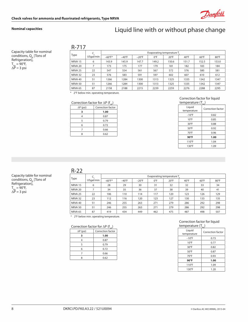
* 2°F below min. operating temperature.
Capacity table for nominal conditions, QN [Tons of Refrigeration], Tliq = 90°F, DP = 3 psi
R-22Type Cv
USgal/min Evaporating temperature Te
–60°F* –40°F –20°F 0°F 20°F 40°F 60°F 80°F
NRVA 15 6 28 29 30 31 32 32 33 34
NRVA 20 7 34 35 36 37 38 39 40 41
NRVA 25 22 106 110 114 117 120 123 126 129
NRVA 32 23 112 116 120 123 127 130 133 135
NRVA 40 51 246 255 263 271 279 286 292 298
NRVA 50 51 246 255 263 271 279 286 292 298
NRVA 65 87 419 434 449 462 475 487 498 507
Correction factor for DP (fDP)DP (psi) Correction factor
3 1.00
4 0.87
5 0.79
6 0.72
7 0.66
8 0.62
Correction factor for liquid temperature (Tliq)
Liquid temperature Correction factor
–10°F 0.73
10°F 0.77
30°F 0.82
50°F 0.87
70°F 0.93
90°F 1.00
110°F 1.09
130°F 1.20
* 2°F below min. operating temperature.
Capacity table for nominal conditions, QN [Tons of Refrigeration], Tliq = 90°F, DP = 3 psi
R-717Type Cv
USgal/min Evaporating temperature Te
–60°F* –40°F –20°F 0°F 20°F 40°F 60°F 80°F
NRVA 15 6 143.9 145.9 147.7 149.2 150.6 151.7 152.5 153.0
NRVA 20 7 173 175 177 179 181 182 183 184
NRVA 25 22 547 554 561 567 572 576 580 581
NRVA 32 23 576 583 591 597 602 607 610 612
NRVA 40 51 1266 1284 1300 1313 1325 1335 1342 1347
NRVA 50 51 1266 1284 1300 1313 1325 1335 1342 1347
NRVA 65 87 2158 2188 2215 2239 2259 2276 2288 2295
Correction factor for DP (fDP)DP (psi) Correction factor
3 1.00
4 0.87
5 0.79
6 0.72
7 0.66
8 0.62
Correction factor for liquid temperature (Tliq)
Liquid temperature Correction factor
–10°F 0.82
10°F 0.85
30°F 0.88
50°F 0.92
70°F 0.96
90°F 1.00
110°F 1.04
130°F 1.09
© Danfoss AC-MCI/MWA), 2013-04 DKRCI.PD.FK0.A3.22 / 521U0094 9
Check valves for ammonia and fluorinated refrigerants, Type NRVA
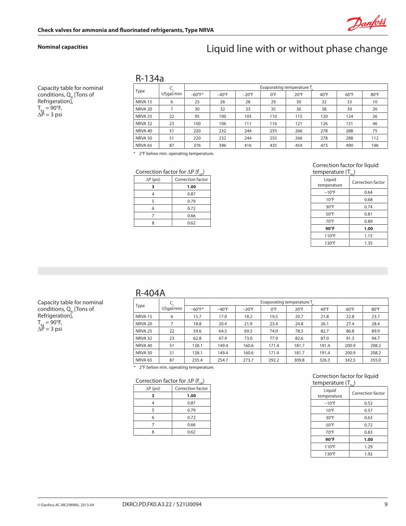
Liquid line with or without phase changeNominal capacities
* 2°F below min. operating temperature.
Capacity table for nominal conditions, QN [Tons of Refrigeration], Tliq = 90°F, DP = 3 psi
R-134aType Cv
USgal/min Evaporating temperature Te
–60°F* –40°F –20°F 0°F 20°F 40°F 60°F 80°F
NRVA 15 6 25 26 28 29 30 32 33 10
NRVA 20 7 30 32 33 35 36 38 39 20
NRVA 25 22 95 100 105 110 115 120 124 26
NRVA 32 23 100 106 111 116 121 126 131 46
NRVA 40 51 220 232 244 255 266 278 288 75
NRVA 50 51 220 232 244 255 266 278 288 112
NRVA 65 87 376 396 416 435 454 473 490 196
Correction factor for DP (fDP)DP (psi) Correction factor
3 1.00
4 0.87
5 0.79
6 0.72
7 0.66
8 0.62
Correction factor for liquid temperature (Tliq)
Liquid temperature Correction factor
–10°F 0.64
10°F 0.68
30°F 0.74
50°F 0.81
70°F 0.89
90°F 1.00
110°F 1.15
130°F 1.35
* 2°F below min. operating temperature.
Capacity table for nominal conditions, QN [Tons of Refrigeration], Tliq = 90°F, DP = 3 psi
R-404AType Cv
USgal/min Evaporating temperature Te
–60°F* –40°F –20°F 0°F 20°F 40°F 60°F 80°F
NRVA 15 6 15.7 17.0 18.2 19.5 20.7 21.8 22.8 23.7
NRVA 20 7 18.8 20.4 21.9 23.4 24.8 26.1 27.4 28.4
NRVA 25 22 59.6 64.5 69.3 74.0 78.5 82.7 86.8 89.9
NRVA 32 23 62.8 67.9 73.0 77.9 82.6 87.0 91.3 94.7
NRVA 40 51 138.1 149.4 160.6 171.4 181.7 191.4 200.9 208.2
NRVA 50 51 138.1 149.4 160.6 171.4 181.7 191.4 200.9 208.2
NRVA 65 87 235.4 254.7 273.7 292.2 309.8 326.3 342.5 355.0
Correction factor for DP (fDP)DP (psi) Correction factor
3 1.00
4 0.87
5 0.79
6 0.72
7 0.66
8 0.62
Correction factor for liquid temperature (Tliq)
Liquid temperature Correction factor
–10°F 0.52
10°F 0.57
30°F 0.63
50°F 0.72
70°F 0.83
90°F 1.00
110°F 1.29
130°F 1.92
10 DKRCI.PD.FK0.A3.22 / 521U0094 © Danfoss AC-MCI/MWA), 2013-04
Check valves for ammonia and fluorinated refrigerants, Type NRVA
Nominal capacities
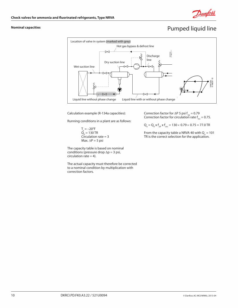
Location of valve in system (marked with grey)
Hot gas bypass & defrost line
Discharge line
Wet suction lineDry suction line
Liquid line without phase change Liquid line with or without phase change
Pumped liquid line
Calculation example (R-134a capacities):
Running conditions in a plant are as follows:
Te = –20°F Q0 = 130 TR Circulation rate = 3 Max. DP = 5 psi
The capacity table is based on nominal conditions (pressure drop Dp = 3 psi, circulation rate = 4).
The actual capacity must therefore be corrected to a nominal condition by multiplication with correction factors.
Correction factor for DP 5 psi fDp = 0.79Correction factor for circulation rate frec = 0.75.
Qn = Q0 x fDP x fcirc = 130 × 0.79 × 0.75 = 77.0 TR
From the capacity table a NRVA 40 with Qn = 101 TR is the correct selection for the application.
© Danfoss AC-MCI/MWA), 2013-04 DKRCI.PD.FK0.A3.22 / 521U0094 11
Check valves for ammonia and fluorinated refrigerants, Type NRVA
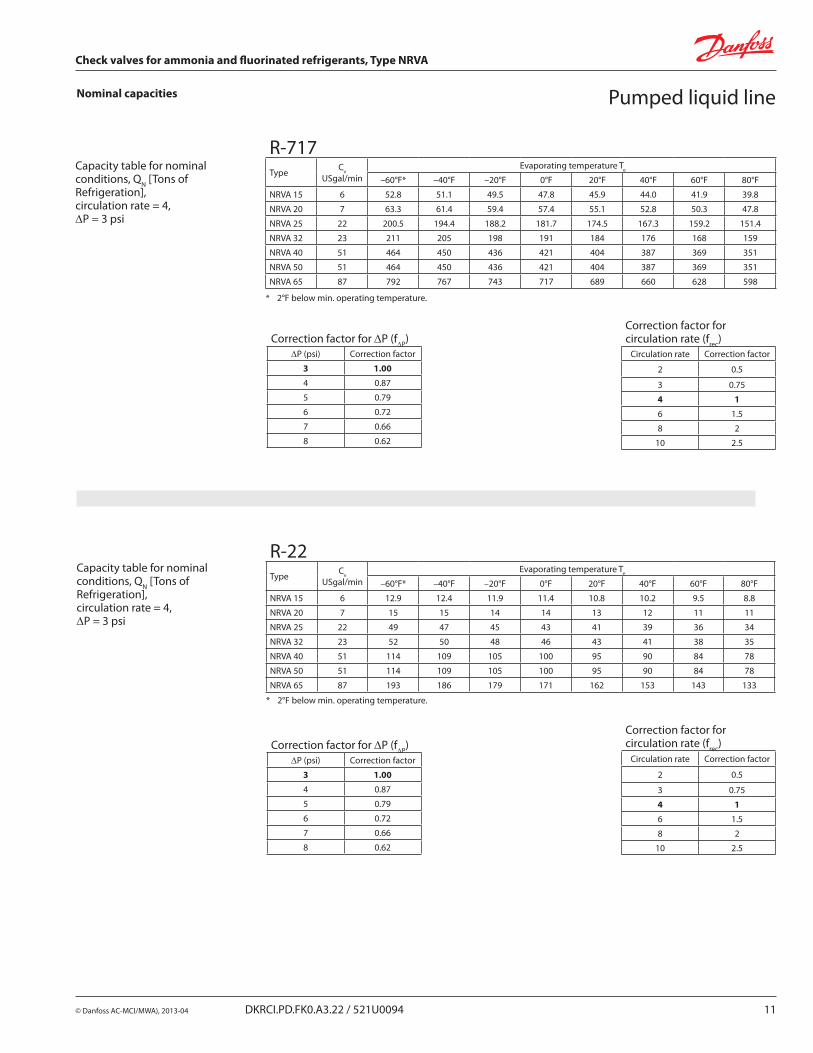
* 2°F below min. operating temperature.
Capacity table for nominal conditions, QN [Tons of Refrigeration], circulation rate = 4,DP = 3 psi
R-717Type Cv
USgal/min Evaporating temperature Te
–60°F* –40°F –20°F 0°F 20°F 40°F 60°F 80°F
NRVA 15 6 52.8 51.1 49.5 47.8 45.9 44.0 41.9 39.8
NRVA 20 7 63.3 61.4 59.4 57.4 55.1 52.8 50.3 47.8
NRVA 25 22 200.5 194.4 188.2 181.7 174.5 167.3 159.2 151.4
NRVA 32 23 211 205 198 191 184 176 168 159
NRVA 40 51 464 450 436 421 404 387 369 351
NRVA 50 51 464 450 436 421 404 387 369 351
NRVA 65 87 792 767 743 717 689 660 628 598
Correction factor for DP (fDP)DP (psi) Correction factor
3 1.00
4 0.87
5 0.79
6 0.72
7 0.66
8 0.62
Correction factor for circulation rate (frec)
Circulation rate Correction factor
2 0.5
3 0.75
4 1
6 1.5
8 2
10 2.5
Nominal capacities
* 2°F below min. operating temperature.
Capacity table for nominal conditions, QN [Tons of Refrigeration], circulation rate = 4, DP = 3 psi
Correction factor for DP (fDP)DP (psi) Correction factor
3 1.00
4 0.87
5 0.79
6 0.72
7 0.66
8 0.62
Correction factor for circulation rate (frec)
Circulation rate Correction factor
2 0.5
3 0.75
4 1
6 1.5
8 2
10 2.5
R-22Type Cv
USgal/min Evaporating temperature Te
–60°F* –40°F –20°F 0°F 20°F 40°F 60°F 80°F
NRVA 15 6 12.9 12.4 11.9 11.4 10.8 10.2 9.5 8.8
NRVA 20 7 15 15 14 14 13 12 11 11
NRVA 25 22 49 47 45 43 41 39 36 34
NRVA 32 23 52 50 48 46 43 41 38 35
NRVA 40 51 114 109 105 100 95 90 84 78
NRVA 50 51 114 109 105 100 95 90 84 78
NRVA 65 87 193 186 179 171 162 153 143 133
Pumped liquid line
12 DKRCI.PD.FK0.A3.22 / 521U0094 © Danfoss AC-MCI/MWA), 2013-04
Check valves for ammonia and fluorinated refrigerants, Type NRVA
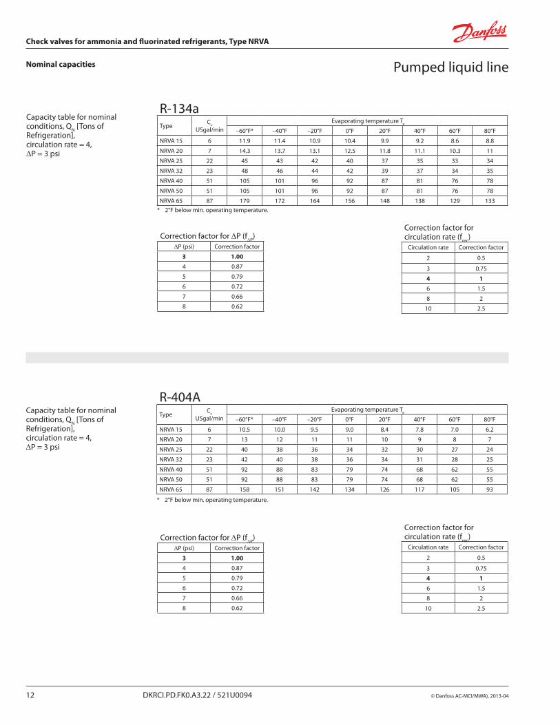
Nominal capacities
* 2°F below min. operating temperature.
Capacity table for nominal conditions, QN [Tons of Refrigeration], circulation rate = 4, DP = 3 psi
Correction factor for DP (fDP)DP (psi) Correction factor
3 1.00
4 0.87
5 0.79
6 0.72
7 0.66
8 0.62
Correction factor for circulation rate (frec)
Circulation rate Correction factor
2 0.5
3 0.75
4 1
6 1.5
8 2
10 2.5
R-134aType Cv
USgal/min Evaporating temperature Te
–60°F* –40°F –20°F 0°F 20°F 40°F 60°F 80°F
NRVA 15 6 11.9 11.4 10.9 10.4 9.9 9.2 8.6 8.8
NRVA 20 7 14.3 13.7 13.1 12.5 11.8 11.1 10.3 11
NRVA 25 22 45 43 42 40 37 35 33 34
NRVA 32 23 48 46 44 42 39 37 34 35
NRVA 40 51 105 101 96 92 87 81 76 78
NRVA 50 51 105 101 96 92 87 81 76 78
NRVA 65 87 179 172 164 156 148 138 129 133
Pumped liquid line
* 2°F below min. operating temperature.
Capacity table for nominal conditions, QN [Tons of Refrigeration], circulation rate = 4, DP = 3 psi
Correction factor for DP (fDP)DP (psi) Correction factor
3 1.00
4 0.87
5 0.79
6 0.72
7 0.66
8 0.62
Correction factor for circulation rate (frec)
Circulation rate Correction factor
2 0.5
3 0.75
4 1
6 1.5
8 2
10 2.5
R-404AType Cv
USgal/min Evaporating temperature Te
–60°F* –40°F –20°F 0°F 20°F 40°F 60°F 80°F
NRVA 15 6 10.5 10.0 9.5 9.0 8.4 7.8 7.0 6.2
NRVA 20 7 13 12 11 11 10 9 8 7
NRVA 25 22 40 38 36 34 32 30 27 24
NRVA 32 23 42 40 38 36 34 31 28 25
NRVA 40 51 92 88 83 79 74 68 62 55
NRVA 50 51 92 88 83 79 74 68 62 55
NRVA 65 87 158 151 142 134 126 117 105 93
© Danfoss AC-MCI/MWA), 2013-04 DKRCI.PD.FK0.A3.22 / 521U0094 13
Check valves for ammonia and fluorinated refrigerants, Type NRVA
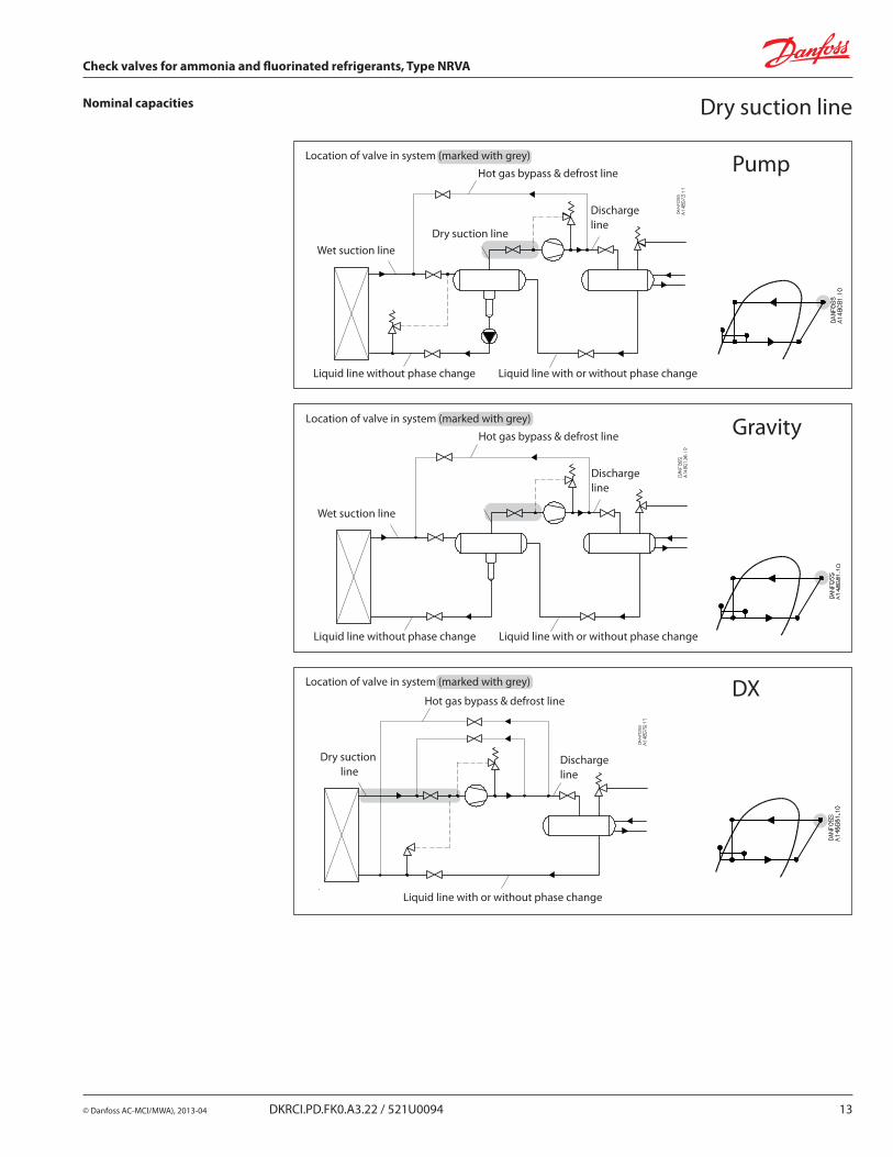
Nominal capacities Dry suction line
PumpLocation of valve in system (marked with grey)
Hot gas bypass & defrost line
Discharge line
Wet suction lineDry suction line
Liquid line without phase change Liquid line with or without phase change
GravityLocation of valve in system (marked with grey)
Hot gas bypass & defrost line
Discharge line
Wet suction line
Liquid line without phase change Liquid line with or without phase change
DXLocation of valve in system (marked with grey)
Hot gas bypass & defrost line
Discharge line
Liquid line with or without phase change
Dry suction line
14 DKRCI.PD.FK0.A3.22 / 521U0094 © Danfoss AC-MCI/MWA), 2013-04
Check valves for ammonia and fluorinated refrigerants, Type NRVA
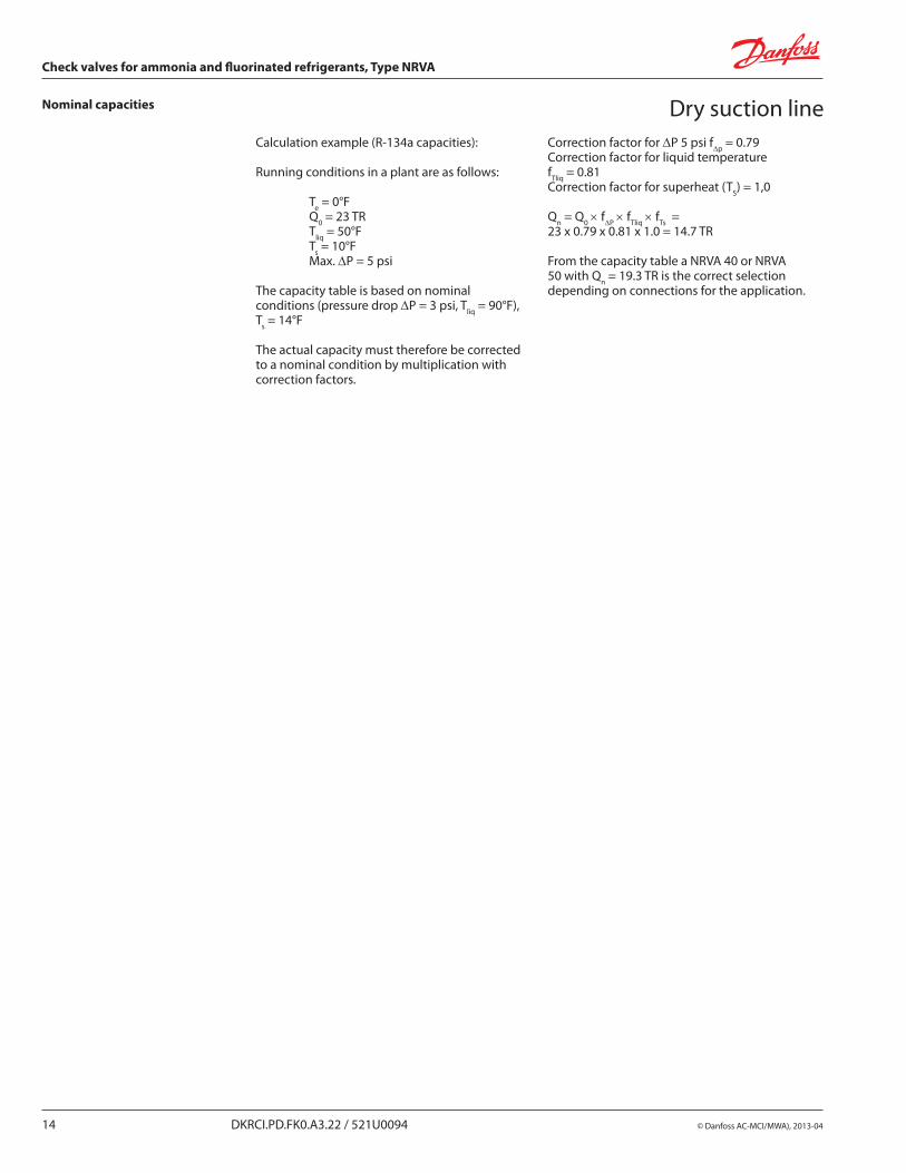
Nominal capacities Dry suction lineCalculation example (R-134a capacities):
Running conditions in a plant are as follows:
Te = 0°F Q0 = 23 TR Tliq = 50°F Ts = 10°F Max. DP = 5 psi
The capacity table is based on nominal conditions (pressure drop DP = 3 psi, Tliq = 90°F), Ts = 14°F
The actual capacity must therefore be corrected to a nominal condition by multiplication with correction factors.
Correction factor for DP 5 psi fDp = 0.79Correction factor for liquid temperaturefTliq = 0.81Correction factor for superheat (TS) = 1,0
Qn = Q0 × fDP × fTliq × fTs = 23 x 0.79 x 0.81 x 1.0 = 14.7 TR
From the capacity table a NRVA 40 or NRVA 50 with Qn = 19.3 TR is the correct selection depending on connections for the application.
© Danfoss AC-MCI/MWA), 2013-04 DKRCI.PD.FK0.A3.22 / 521U0094 15
Check valves for ammonia and fluorinated refrigerants, Type NRVA
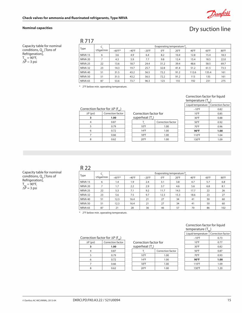
Nominal capacities Dry suction line
* 2°F below min. operating temperature.
Capacity table for nominal conditions, QN [Tons of Refrigeration], Tliq = 90°F, DP = 3 psi
R 717Type Cv
USgal/min Evaporating temperature Te
–60°F* –40°F –20°F 0°F 20°F 40°F 60°F 80°F
NRVA 15 6 3.6 4.9 6.4 8.2 10.4 12.8 15.4 18.3
NRVA 20 7 4.3 5.9 7.7 9.8 12.4 15.4 18.5 22.0
NRVA 25 22 13.6 18.7 24.4 31.2 39.4 48.6 58.5 69.7
NRVA 32 23 14.3 19.7 25.7 32.8 41.4 51.2 61.5 73.3
NRVA 40 51 31.5 43.2 56.5 72.2 91.2 112.6 135.4 161
NRVA 50 51 31.5 43.2 56.5 72.2 91.2 113 135 161
NRVA 65 87 53.6 73.7 96.3 123 155 192 231 275
Correction factor for DP (fDP)DP (psi) Correction factor
3 1.00
4 0.87
5 0.79
6 0.72
7 0.66
8 0.62
Correction factor for superheat (TS)
Τs Correction factor
10°F 1.00
14°F 1.00
18°F 1.00
20°F 1.00
Correction factor for liquid temperature (Tliq)Liquid temperature Correction factor
–10°F 0.82
10°F 0.85
30°F 0.88
50°F 0.92
70°F 0.96
90°F 1.00
110°F 1.04
130°F 1.09
Correction factor for DP (fDP)DP (psi) Correction factor
3 1.00
4 0.87
5 0.79
6 0.72
7 0.66
8 0.62
Correction factor for superheat (TS)
Τs Correction factor
10°F 1.00
14°F 1.00
18°F 1.00
20°F 1.00
Correction factor for liquid temperature (Tliq)Liquid temperature Correction factor
–10°F 0.73
10°F 0.77
30°F 0.82
50°F 0.87
70°F 0.93
90°F 1.00
110°F 1.09
130°F 1.20
* 2°F below min. operating temperature.
Capacity table for nominal conditions, QN [Tons of Refrigeration], Tliq = 90°F, DP = 3 psi
R 22Type Cv
USgal/min Evaporating temperature Te
–60°F* –40°F –20°F 0°F 20°F 40°F 60°F 80°F
NRVA 15 6 1.4 1.9 2.4 3.1 3.8 4.7 5.7 6.8
NRVA 20 7 1.7 2.2 2.9 3.7 4.6 5.6 6.8 8.1
NRVA 25 22 5.3 7.1 9.2 11.7 14.5 17.7 22 26
NRVA 32 23 5.6 7.5 9.7 12.3 15.3 18.6 23 27
NRVA 40 51 12.3 16.4 21 27 34 41 50 60
NRVA 50 51 12.3 16.4 21 27 34 41 50 60
NRVA 65 87 21 28 36 46 57 70 86 102
16 DKRCI.PD.FK0.A3.22 / 521U0094 © Danfoss AC-MCI/MWA), 2013-04
Check valves for ammonia and fluorinated refrigerants, Type NRVA
Nominal capacities Dry suction line
Correction factor for DP (fDP)DP (psi) Correction factor
3 1.00
4 0.87
5 0.79
6 0.72
7 0.66
8 0.62
Correction factor for superheat (TS)
Τs Correction factor
10°F 1.00
14°F 1.00
18°F 1.00
20°F 1.00
Correction factor for liquid temperature (Tliq)Liquid temperature Correction factor
–10°F 0.64
10°F 0.68
30°F 0.74
50°F 0.81
70°F 0.89
90°F 1.00
110°F 1.15
130°F 1.35
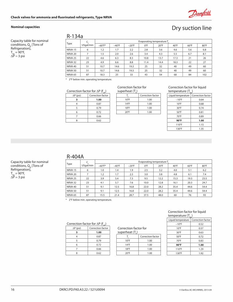
* 2°F below min. operating temperature.
Capacity table for nominal conditions, QN [Tons of Refrigeration], Tliq = 90°F, DP = 3 psi
R-134aType Cv
USgal/min Evaporating temperature Te
–60°F* –40°F –20°F 0°F 20°F 40°F 60°F 80°F
NRVA 15 6 1.2 1.7 2.2 2.8 3.6 4.6 5.6 6.8
NRVA 20 7 1.5 2.0 2.6 3.4 4.3 5.5 6.7 8.1
NRVA 25 22 4.6 6.3 8.3 10.8 13.7 17.3 21 26
NRVA 32 23 4.9 6.6 8.8 11.4 14.4 18.3 22 27
NRVA 40 51 10.7 14.6 19.3 25 32 40 49 60
NRVA 50 51 10.7 14.6 19.3 25 32 40 49 60
NRVA 65 87 18.3 25 33 43 54 68 84 102
Correction factor for DP (fDP)DP (psi) Correction factor
3 1.00
4 0.87
5 0.79
6 0.72
7 0.66
8 0.62
Correction factor for superheat (TS)
Τs Correction factor
10°F 1.00
14°F 1.00
18°F 1.00
20°F 1.00
Correction factor for liquid temperature (Tliq)Liquid temperature Correction factor
–10°F 0.52
10°F 0.57
30°F 0.63
50°F 0.72
70°F 0.83
90°F 1.00
110°F 1.29
130°F 1.92
* 2°F below min. operating temperature.
Capacity table for nominal conditions, QN [Tons of Refrigeration], Tliq = 90°F, DP = 3 psi
R-404AType Cv
USgal/min Evaporating temperature Te
–60°F* –40°F –20°F 0°F 20°F 40°F 60°F 80°F
NRVA 15 6 1.0 1.4 1.9 2.5 3.2 4.0 5.1 6.2
NRVA 20 7 1.2 1.7 2.3 3.0 3.8 4.8 6.1 7.4
NRVA 25 22 3.9 5.4 7.3 9.5 12.2 15.3 19.3 23.5
NRVA 32 23 4.1 5.7 7.6 10.0 12.8 16.1 20.3 24.7
NRVA 40 51 9.1 12.5 16.8 22.0 28.2 35.4 44.6 54.4
NRVA 50 51 9.1 12.5 16.8 22.0 28.2 35.4 44.6 54.4
NRVA 65 87 15.5 21.4 28.7 37.5 48.0 60 76 93
© Danfoss AC-MCI/MWA), 2013-04 DKRCI.PD.FK0.A3.22 / 521U0094 17
Check valves for ammonia and fluorinated refrigerants, Type NRVA
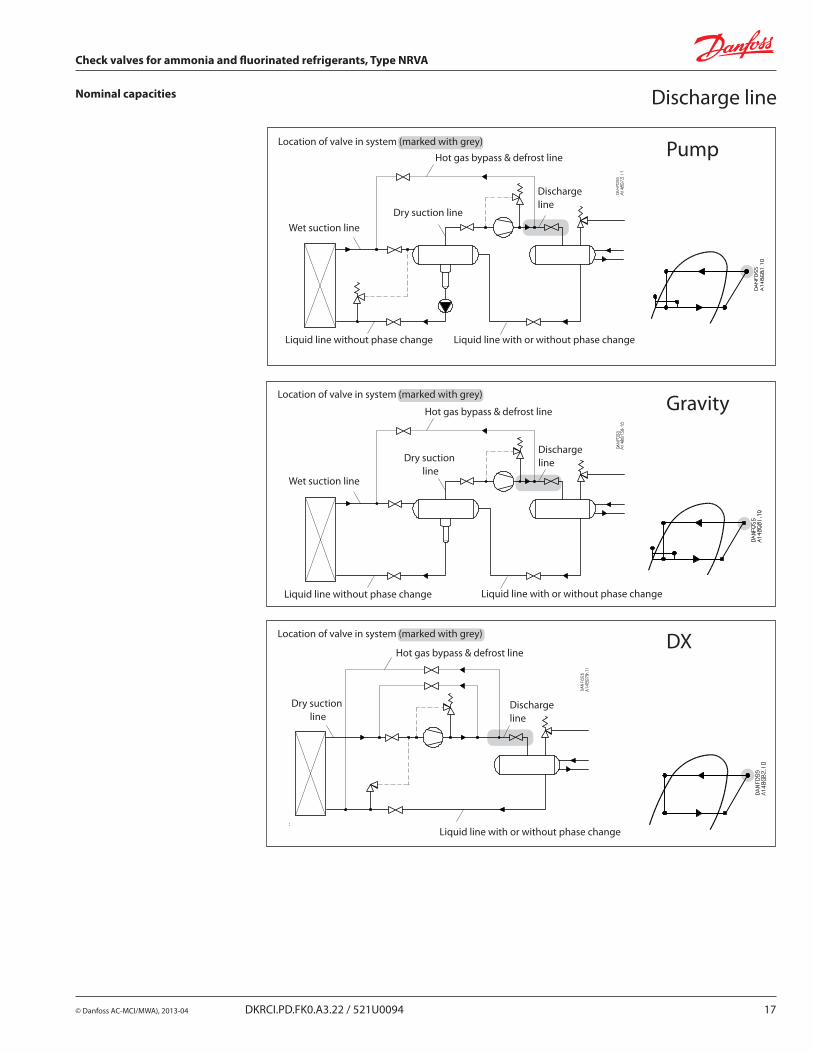
Nominal capacities Discharge line
Location of valve in system (marked with grey)
Hot gas bypass & defrost line
Discharge line
Wet suction lineDry suction line
Liquid line without phase change Liquid line with or without phase change
Pump
Location of valve in system (marked with grey) Gravity
Location of valve in system (marked with grey)
Hot gas bypass & defrost line
Discharge line
Liquid line with or without phase change
Dry suction line
DX
Hot gas bypass & defrost line
Discharge line
Liquid line with or without phase change
Dry suction line
Liquid line without phase change
Wet suction line
18 DKRCI.PD.FK0.A3.22 / 521U0094 © Danfoss AC-MCI/MWA), 2013-04
Check valves for ammonia and fluorinated refrigerants, Type NRVA
Nominal capacities
Calculation example (R-717 capacities):
Running conditions in a plant are as follows:
Te = 0°F Qo = 18 TR Tliq = 50 °F Max. DP = 7 psi Tdisch = 120°F
The capacity table is based on nominel conditions (DP = 3 psi, Tliq = 90 °F, Pdisch= 185 psi, Tdisch = 180°F).
The actual capacity must therefore be corrected to a nominal condition by multiplication with correction factors.
Discharge lineCorrection factor for DP 7 psi fDP = 0.67.Correction factor for liquid temperature f Tliq = 0.92.Correction factor for Tdisch 120°F, fdisch = 0.95.Correction factor for Pdisch 185 psi, fpdisch = 1.0.
Qn = Qo × fDP × fTliq × fcirc × fPdisch = 18 × 0.67 × 0.92 × 0.95 × 1.0 = 10.5 TR
From the capacity table a NRVA 15 with Qn= 16.4 TR is the correct selection for the application.
© Danfoss AC-MCI/MWA), 2013-04 DKRCI.PD.FK0.A3.22 / 521U0094 19
Check valves for ammonia and fluorinated refrigerants, Type NRVA
Nominal capacities
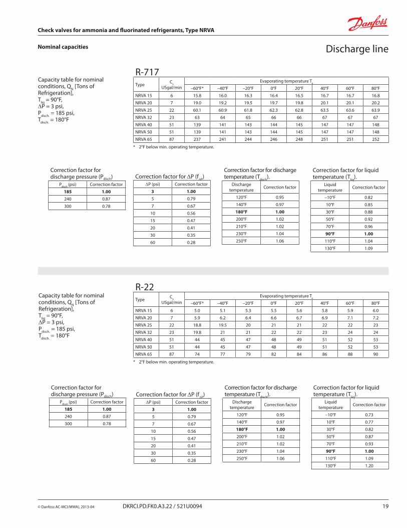
* 2°F below min. operating temperature.
R-717Type Cv
USgal/minEvaporating temperature Te
–60°F* –40°F –20°F 0°F 20°F 40°F 60°F 80°F
NRVA 15 6 15.8 16.0 16.3 16.4 16.5 16.7 16.7 16.8
NRVA 20 7 19.0 19.2 19.5 19.7 19.8 20.1 20.1 20.2
NRVA 25 22 60.1 60.9 61.8 62.3 62.8 63.5 63.6 63.9
NRVA 32 23 63 64 65 66 66 67 67 67
NRVA 40 51 139 141 143 144 145 147 147 148
NRVA 50 51 139 141 143 144 145 147 147 148
NRVA 65 87 237 241 244 246 248 251 251 252
Capacity table for nominal conditions, QN [Tons of Refrigeration], Tliq = 90°F, DP = 3 psi, Pdisch. = 185 psi, Tdisch. = 180°F
Correction factor for discharge pressure (Pdisch)
Pdisch (psi) Correction factor
185 1.00
240 0.87
300 0.78
Correction factor for DP (fDP)DP (psi) Correction factor
3 1.00
5 0.79
7 0.67
10 0.56
15 0.47
20 0.41
30 0.35
60 0.28
Correction factor for discharge temperature (Tdisch).
Discharge temperature Correction factor
120°F 0.95
140°F 0.97
180°F 1.00
200°F 1.02
210°F 1.02
230°F 1.04
250°F 1.06
Correction factor for liquid temperature (Tliq).
Liquid temperature Correction factor
–10°F 0.82
10°F 0.85
30°F 0.88
50°F 0.92
70°F 0.96
90°F 1.00
110°F 1.04
130°F 1.09
Discharge line
Correction factor for discharge pressure (Pdisch)
Pdisch (psi) Correction factor
185 1.00
240 0.87
300 0.78
Correction factor for DP (fDP)DP (psi) Correction factor
3 1.00
5 0.79
7 0.67
10 0.56
15 0.47
20 0.41
30 0.35
60 0.28
Correction factor for discharge temperature (Tdisch).
Discharge temperature Correction factor
120°F 0.95
140°F 0.97
180°F 1.00
200°F 1.02
210°F 1.02
230°F 1.04
250°F 1.06
Correction factor for liquid temperature (Tliq).
Liquid temperature Correction factor
–10°F 0.73
10°F 0.77
30°F 0.82
50°F 0.87
70°F 0.93
90°F 1.00
110°F 1.09
130°F 1.20
* 2°F below min. operating temperature.
R-22Type Cv
USgal/minEvaporating temperature Te
–60°F* –40°F –20°F 0°F 20°F 40°F 60°F 80°F
NRVA 15 6 5.0 5.1 5.3 5.5 5.6 5.8 5.9 6.0
NRVA 20 7 5.9 6.2 6.4 6.6 6.7 6.9 7.1 7.2
NRVA 25 22 18.8 19.5 20 21 21 22 22 23
NRVA 32 23 19.8 21 21 22 22 23 24 24
NRVA 40 51 44 45 47 48 49 51 52 53
NRVA 50 51 44 45 47 48 49 51 52 53
NRVA 65 87 74 77 79 82 84 86 88 90
Capacity table for nominal conditions, QN [Tons of Refrigeration], Tliq = 90°F, DP = 3 psi, Pdisch. = 185 psi, Tdisch. = 180°F
20 DKRCI.PD.FK0.A3.22 / 521U0094 © Danfoss AC-MCI/MWA), 2013-04
Check valves for ammonia and fluorinated refrigerants, Type NRVA
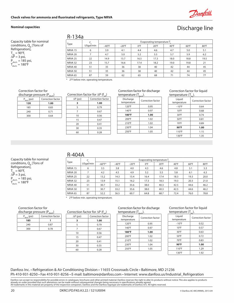
Nominal capacities Discharge line
Correction factor for discharge pressure (Pdisch)
Pdisch (psi) Correction factor
120 1.00
185 0.83
240 0.71
300 0.64
Correction factor for DP (fDP)DP (psi) Correction factor
3 1.00
5 0.79
7 0.67
10 0.56
15 0.47
20 0.41
30 0.35
60 0.28
Correction factor for discharge temperature (Tdisch).
Discharge temperature Correction factor
120°F 0.95
140°F 0.97
180°F 1.00
200°F 1.02
210°F 1.02
230°F 1.04
250°F 1.05
Correction factor for liquid temperature (Tliq).
Liquid temperature Correction factor
–10°F 0.64
10°F 0.68
30°F 0.74
50°F 0.81
70°F 0.89
90°F 1.00
110°F 1.15
130°F 1.35
* 2°F below min. operating temperature.
R-134aType Cv
USgal/minEvaporating temperature Te
–40°F –20°F 0°F 20°F 40°F 60°F 80°F
NRVA 15 6 3.9 4.1 4.4 4.6 4.7 5.0 5.1
NRVA 20 7 4.7 5.0 5.2 5.5 5.7 5.9 6.2
NRVA 25 22 14.9 15.7 16.5 17.3 18.0 18.8 19.5
NRVA 32 23 15.7 16.6 17.4 18.2 19.0 19.8 21
NRVA 40 51 35 36 38 40 42 44 45
NRVA 50 51 35 36 38 40 42 44 45
NRVA 65 87 59 62 65 68 71 74 77
Capacity table for nominal conditions, QN [Tons of Refrigeration], Tliq = 90°F, DP = 3 psi, Pdisch. = 185 psi, Tdisch. = 180°F
Correction factor for discharge pressure (Pdisch)
Pdisch (psi) Correction factor
185 1
240 0.87
300 0.78
Correction factor for DP (fDP)DP (psi) Correction factor
3 1.00
5 0.79
7 0.67
10 0.56
15 0.47
20 0.41
30 0.35
60 0.28
Correction factor for discharge temperature (Tdisch).
Discharge temperature Correction factor
120°F 0.95
140°F 0.97
180°F 1.00
200°F 1.02
210°F 1.02
230°F 1.04
250°F 1.05
Correction factor for liquid temperature (Tliq).
Liquid temperature Correction factor
–10°F 0.52
10°F 0.57
30°F 0.63
50°F 0.72
70°F 0.83
90°F 1.00
110°F 1.29
130°F 1.92
* 2°F below min. operating temperature.
R-404AType Cv
USgal/minEvaporating temperature Te
–60°F* –40°F –20°F 0°F 20°F 40°F 60°F 80°F
NRVA 15 6 3.5 3.8 4.0 4.3 4.6 4.8 5.1 5.3
NRVA 20 7 4.2 4.5 4.9 5.2 5.5 5.8 6.1 6.3
NRVA 25 22 13.2 14.3 15.4 16.4 17.4 18.3 19.3 20.0
NRVA 32 23 13.9 15.1 16.2 17.3 18.3 19.3 20.3 21.0
NRVA 40 51 30.7 33.2 35.6 38.0 40.3 42.5 44.6 46.2
NRVA 50 51 30.7 33.2 35.6 38.0 40.3 42.5 44.6 46.2
NRVA 65 87 52.2 56.5 60.7 64.8 68.7 72.4 76.0 78.8
Capacity table for nominal conditions, QN [Tons of Refrigeration], Tliq = 90°F, DP = 3 psi, Pdisch. = 185 psi, Tdisch. = 180°F
Danfoss Inc. • Refrigeration & Air Conditioning Division • 11655 Crossroads Circle • Baltimore, MD 21236 Ph 410-931-8250 • Fax 410-931-8256 • E-mail: [email protected] • Internet: www.danfoss.us/Industrial_Refrigeration